operating the die casting machine · operating the die casting machine page 1 introduction die...
TRANSCRIPT

Publication #E-902
operating the die casting M A C H I N E
By: Henry Bakemeyer
NORTH AMERICAN DIE CASTING ASSOCIATION

Although great care has been taken to provide accurate and current information, neither the author(s) nor the publisher, nor anyone else associated with this publication, shall be liable for any loss, damage or liability directly or indirectly caused or alleged to be caused by this book. The material contained
herein is not intended to provide specific advice or recommendations for any specific situation. Any opinions expressed by the author(s) are not necessarily those of NADCA.
Trademark notice: Product or corporate names may be trademarks or registered trademarks and are used only for identification and explanation without intent to infringe nor endorse the product or corporation.
© 2008 by North American Die Casting Association, Arlington Heights, Illinois. All Rights Reserved.
Neither this book nor any parts may be reproduced or transmitted in any form or by any means, electronic or mechanical, including photocopying, microfilming, and recording, or by any information
storage and retrieval system, without permission in writing from the publisher.

Operating the Die Casting Machine Page i
ENGINEERING CAREER DEVELOPMENT SERIES
The NADCA Education Program
The North American Die Casting Association’s education program consists of a series of courses designed to help each individual develop his career within the die casting industry. The individual may prepare for advancement or broaden his understanding of subjects within his fi eld of specialization through the NADCA courses.
Each course is supplemented with a thorough textbook. The textbook remains a useful reference long after the course is completed. Although each textbook is complete, the instructor may include information that is new since the printing of the textbook, that is unique to the student’s plant, or that more fully explains the material. The student should make his own notes of such information.

Page ii Operating the Die Casting Machine
Operating the Die Casting Machine Page iii
TABLE OF CONTENTS
Chapter Page
Introduction ……………………………………………………………… 1
1 Process Description …………………………………………………… 3
2 Die Casting Die ………………………………………………………… 9
3 Die Casting Machine …………………………………………………… 13
4 Machine Closing and Injection ………………………………………… 33
5 Controls ………………………………………………………………… 51
6 Setup and SMED ……………………………………………………… 63
7 Start up & Shut down Procedures …………………………………… 75
8 Normal Operation ……………………………………………………… 83
9 Eliminating Casting Defects …………………………………………… 87
10 Safety …………………………………………………………………… 105
Appendix ………………………………………………………………… A1
Reference ……………………………………………………………… A5

Page iv Operating the Die Casting Machine
Operating the Die Casting Machine Page 1
INTRODUCTION
Die casting is a complex process. The operator of a die casting machine is involved with molten metal, a very complex machine, expensive dies, extremely high pressures, critical temperature control, and a whole set of special safety considerations. Unlike a press operation - where the operator loads and unloads, and the press and die make the part - the die casting operator is called upon to manipulate, adjust, and otherwise control the above mentioned factors until “good” parts are being made. Additionally complicating the situation is the fact that some of these factors tend to “drift” out of adjustment during the running of the machine.
The die casting machine operator must be constantly alert to the condition of the castings he is making. He must be able to recognize defective conditions and be able to take corrective action. During this time he still must continue repetitive functions associated with the machine cycle. In addition, he must take care of the machine and die. This care includes housekeeping, lubrication, and the special activities associated with the molten metal.
These introductory comments are not intended to scare the potential operator. Instead, the intent is to emphasize the need for careful and complete training of all die casting machine operators. Enlightened management should provide such training, and the individual operator must be motivated to respond positively to training efforts.

Page 2 Operating the Die Casting Machine
Introduction
Operating the Die Casting Machine Page 3
Chapter 1PROCESS DESCRIPTIONS
In die casting, molten metal is forced into steel dies. High pressures insure that the molten metal completely fi lls the empty space between the die halves in a fraction of a second. As the molten metal is held in the die, heat fl ows out of the metal and into the die, solidifying the metal. When solidifi cation is complete, the die is opened and the solid die casting is removed. This solid casting is generally called the "shot”. The process of injecting the metal is also called the “shot”.
This process has many advantages over other manufacturing processes. The primary advantage is the ability to produce a net shape (or near net shape) component in one manufacturing step. The major disadvantage of the die casting process is internal porosity. This disadvantage has led to the development of process changes and improvements to the process we know as “Conventional High Pressure Die Casting”. “Conventional High Pressure Die Casting” has been modifi ed by the addition of vacuum technology and very high cavity pressures in “Squeeze casting”. There also are new processes that cast the metal in a semi-solid state such as “Thixomoulding®” and SOD (Slurry on Demand) to name a few.
For the purposes of this text we will be focused on “Conventional High Pressure Die Casting”, both the Cold and Hot Chamber processes.
Page 4 Operating the Die Casting Machine
Process Descriptions
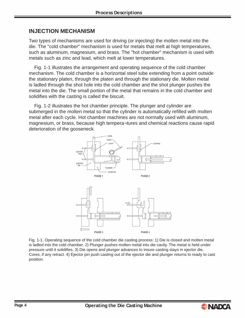
INJECTION MECHANISMTwo types of mechanisms are used for driving (or injecting) the molten metal into the die. The "cold chamber" mechanism is used for metals that melt at high temperatures, such as aluminum, magnesium, and brass. The "hot chamber" mechanism is used with metals such as zinc and lead, which melt at lower temperatures.
Fig. 1-1 illustrates the arrangement and operating sequence of the cold chamber mechanism. The cold chamber is a horizontal steel tube extending from a point outside the stationary platen, through the platen and through the stationary die. Molten metal is ladled through the shot hole into the cold chamber and the shot plunger pushes the metal into the die. The small portion of the metal that remains in the cold chamber and solidifi es with the casting is called the biscuit.
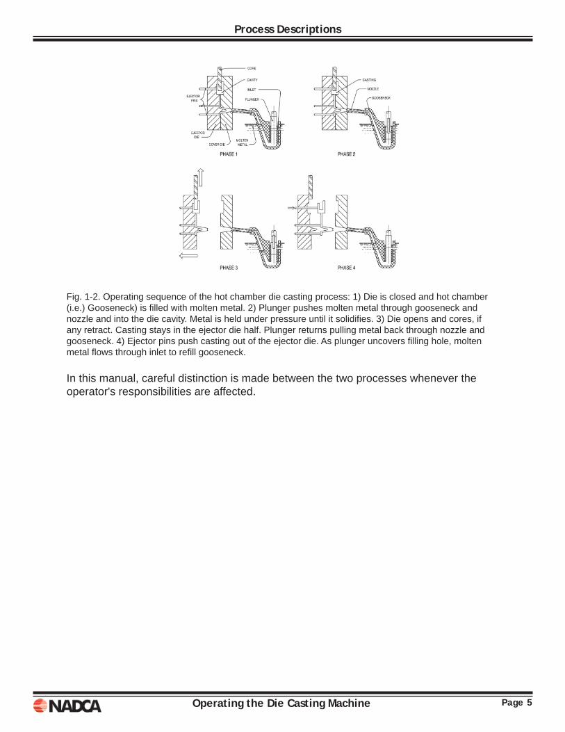
Fig. 1-2 illustrates the hot chamber principle. The plunger and cylinder are submerged in the molten metal so that the cylinder is automatically refi lled with molten metal after each cycle. Hot chamber machines are not normally used with aluminum, magnesium, or brass, because high tempera¬tures and chemical reactions cause rapid deterioration of the gooseneck.
Fig. 1-1. Operating sequence of the cold chamber die casting process: 1) Die is closed and molten metal is ladled into the cold chamber. 2) Plunger pushes molten metal into die cavity. The metal is held under pressure until it solidifi es. 3) Die opens and plunger advances to insure casting stays in ejector die. Cores, if any retract. 4) Ejector pin push casting out of the ejector die and plunger returns to ready to cast position.
Page 5Operating the Die Casting Machine
Process Descriptions
Fig. 1-2. Operating sequence of the hot chamber die casting process: 1) Die is closed and hot chamber (i.e.) Gooseneck) is fi lled with molten metal. 2) Plunger pushes molten metal through gooseneck and nozzle and into the die cavity. Metal is held under pressure until it solidifi es. 3) Die opens and cores, if any retract. Casting stays in the ejector die half. Plunger returns pulling metal back through nozzle and gooseneck. 4) Ejector pins push casting out of the ejector die. As plunger uncovers fi lling hole, molten metal fl ows through inlet to refi ll gooseneck.
In this manual, careful distinction is made between the two processes whenever the operator's responsibilities are affected.
Page 6 Operating the Die Casting Machine
Process Descriptions
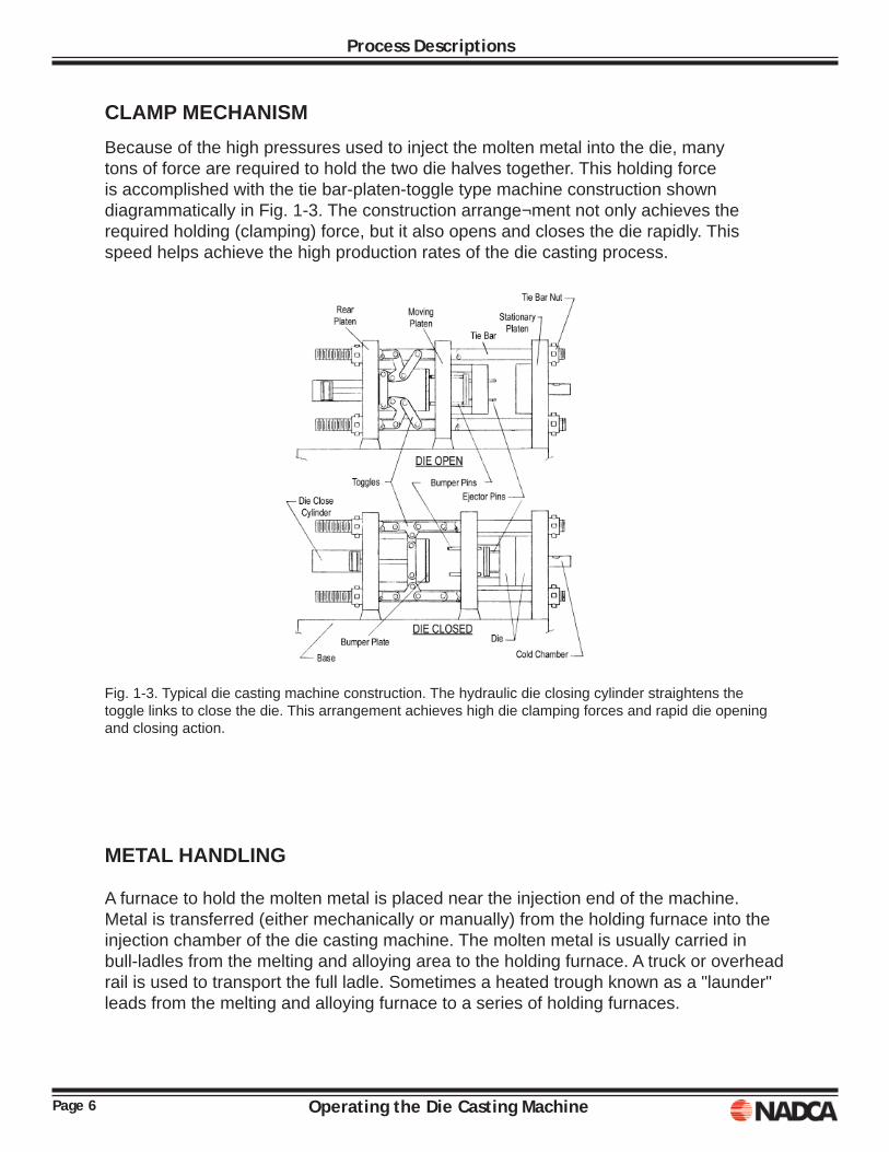
CLAMP MECHANISMBecause of the high pressures used to inject the molten metal into the die, many tons of force are required to hold the two die halves together. This holding force is accomplished with the tie bar-platen-toggle type machine construction shown diagrammatically in Fig. 1-3. The construction arrange¬ment not only achieves the required holding (clamping) force, but it also opens and closes the die rapidly. This speed helps achieve the high production rates of the die casting process.
Fig. 1-3. Typical die casting machine construction. The hydraulic die closing cylinder straightens the toggle links to close the die. This arrangement achieves high die clamping forces and rapid die opening and closing action.
METAL HANDLING
A furnace to hold the molten metal is placed near the injection end of the machine. Metal is transferred (either mechanically or manually) from the holding furnace into the injection chamber of the die casting machine. The molten metal is usually carried in bull-ladles from the melting and alloying area to the holding furnace. A truck or overhead rail is used to transport the full ladle. Sometimes a heated trough known as a "launder" leads from the melting and alloying furnace to a series of holding furnaces.
Page 7Operating the Die Casting Machine
Process Descriptions
TRIMMING
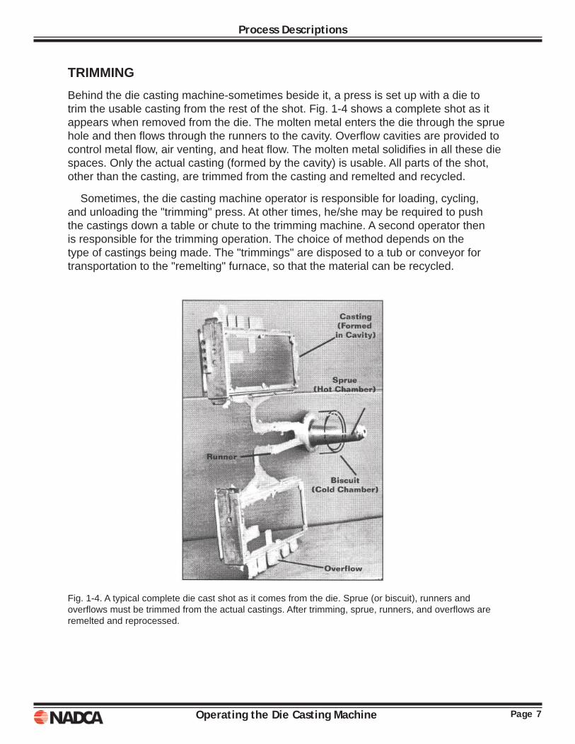
Behind the die casting machine-sometimes beside it, a press is set up with a die to trim the usable casting from the rest of the shot. Fig. 1-4 shows a complete shot as it appears when removed from the die. The molten metal enters the die through the sprue hole and then fl ows through the runners to the cavity. Overfl ow cavities are provided to control metal fl ow, air venting, and heat fl ow. The molten metal solidifi es in all these die spaces. Only the actual casting (formed by the cavity) is usable. All parts of the shot, other than the casting, are trimmed from the casting and remelted and recycled.
Sometimes, the die casting machine operator is responsible for loading, cycling, and unloading the "trimming" press. At other times, he/she may be required to push the castings down a table or chute to the trimming machine. A second operator then is responsible for the trimming operation. The choice of method depends on the type of castings being made. The "trimmings" are disposed to a tub or conveyor for transportation to the "remelting" furnace, so that the material can be recycled.
Fig. 1-4. A typical complete die cast shot as it comes from the die. Sprue (or biscuit), runners and overfl ows must be trimmed from the actual castings. After trimming, sprue, runners, and overfl ows are remelted and reprocessed.

Page 8 Operating the Die Casting Machine
Process Descriptions
Operating the Die Casting Machine Page 9
Chapter 2DIE CASTING DIES
The die uses the energy of the machine to form the desired part. It is impor¬tant for the machine operator to know the names of different parts of the die. Many die features have the same name as the part of the shot that they form. As shown in Fig. 1-4, these parts include biscuits, sprues, runners, gates, overfl ows and vents. The space in which the casting is formed usually called the die cavity.
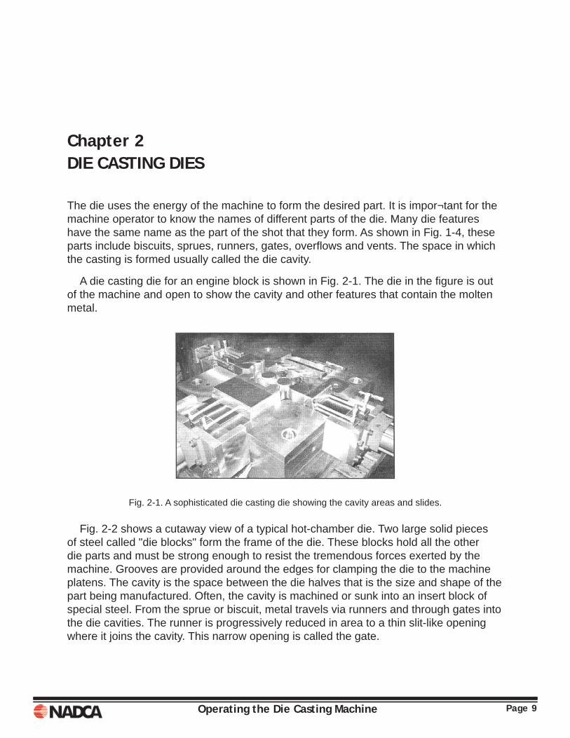
A die casting die for an engine block is shown in Fig. 2-1. The die in the fi gure is out of the machine and open to show the cavity and other features that contain the molten metal.
Fig. 2-1. A sophisticated die casting die showing the cavity areas and slides.
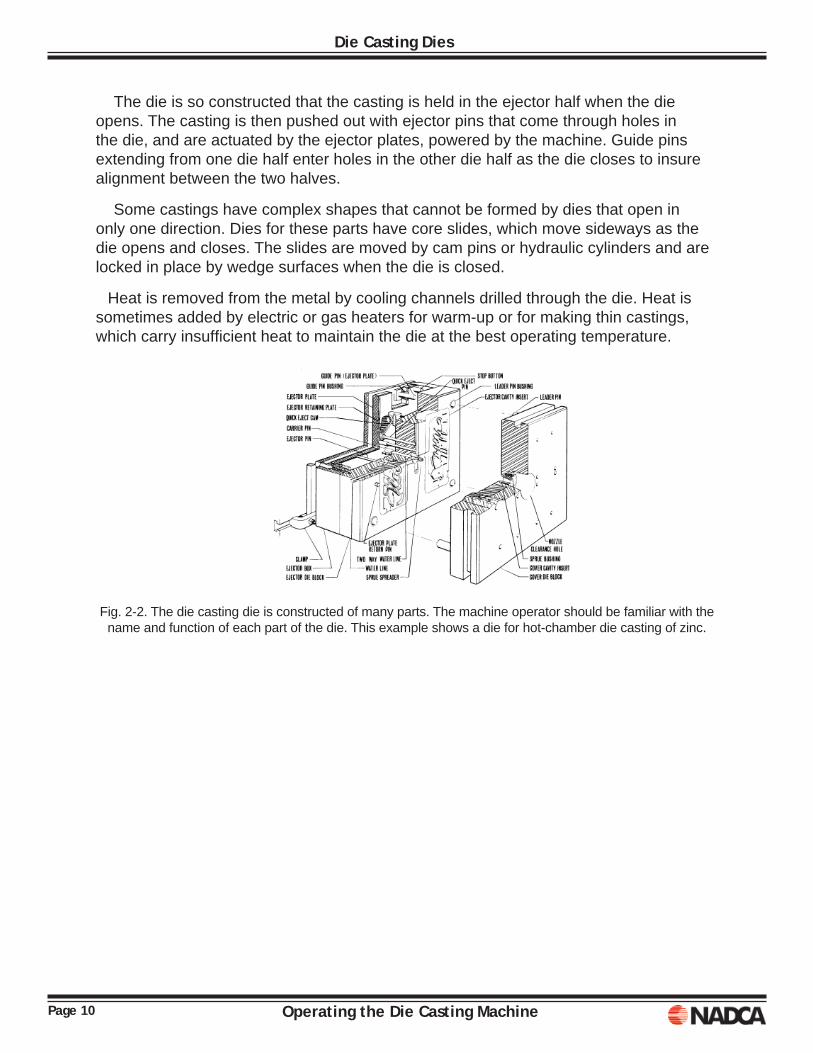
Fig. 2-2 shows a cutaway view of a typical hot-chamber die. Two large solid pieces of steel called "die blocks" form the frame of the die. These blocks hold all the other die parts and must be strong enough to resist the tremendous forces exerted by the machine. Grooves are provided around the edges for clamping the die to the machine platens. The cavity is the space between the die halves that is the size and shape of the part being manufactured. Often, the cavity is machined or sunk into an insert block of special steel. From the sprue or biscuit, metal travels via runners and through gates into the die cavities. The runner is progressively reduced in area to a thin slit-like opening where it joins the cavity. This narrow opening is called the gate.
Page 10 Operating the Die Casting Machine
Die Casting Dies
The die is so constructed that the casting is held in the ejector half when the die opens. The casting is then pushed out with ejector pins that come through holes in the die, and are actuated by the ejector plates, powered by the machine. Guide pins extending from one die half enter holes in the other die half as the die closes to insure alignment between the two halves.
Some castings have complex shapes that cannot be formed by dies that open in only one direction. Dies for these parts have core slides, which move sideways as the die opens and closes. The slides are moved by cam pins or hydraulic cylinders and are locked in place by wedge surfaces when the die is closed.
Heat is removed from the metal by cooling channels drilled through the die. Heat is sometimes added by electric or gas heaters for warm-up or for making thin castings, which carry insuffi cient heat to maintain the die at the best operating temperature.
Fig. 2-2. The die casting die is constructed of many parts. The machine operator should be familiar with the name and function of each part of the die. This example shows a die for hot-chamber die casting of zinc.
Page 11Operating the Die Casting Machine
Die Casting Dies
DIE MAINTENANCEThe DCM operator also has responsibility to maintain the die good working order. This includes assuring that there are no practices undertaken that could shorten die life. The following list of practices should be followed to assure the die life is maximized:
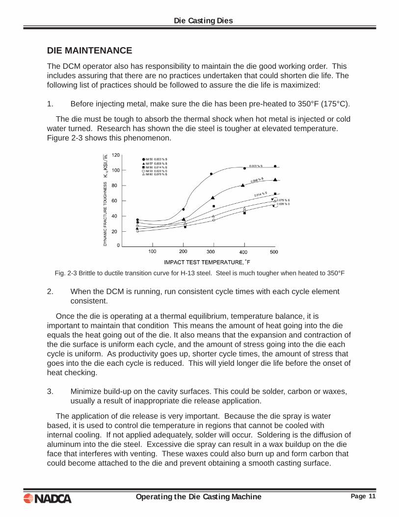
1. Before injecting metal, make sure the die has been pre-heated to 350°F (175°C).
The die must be tough to absorb the thermal shock when hot metal is injected or cold water turned. Research has shown the die steel is tougher at elevated temperature. Figure 2-3 shows this phenomenon.
Fig. 2-3 Brittle to ductile transition curve for H-13 steel. Steel is much tougher when heated to 350°F
2. When the DCM is running, run consistent cycle times with each cycle element consistent.
Once the die is operating at a thermal equilibrium, temperature balance, it is important to maintain that condition This means the amount of heat going into the die equals the heat going out of the die. It also means that the expansion and contraction of the die surface is uniform each cycle, and the amount of stress going into the die each cycle is uniform. As productivity goes up, shorter cycle times, the amount of stress that goes into the die each cycle is reduced. This will yield longer die life before the onset of heat checking.
3. Minimize build-up on the cavity surfaces. This could be solder, carbon or waxes, usually a result of inappropriate die release application.
The application of die release is very important. Because the die spray is water based, it is used to control die temperature in regions that cannot be cooled with internal cooling. If not applied adequately, solder will occur. Soldering is the diffusion of aluminum into the die steel. Excessive die spray can result in a wax buildup on the die face that interferes with venting. These waxes could also burn up and form carbon that could become attached to the die and prevent obtaining a smooth casting surface.

Page 12 Operating the Die Casting Machine
Die Casting Dies
Operating the Die Casting Machine Page 13
Chapter 3THE DIE CASTING MACHINE (DCM)
The die casting machine is the most important machine in the die casting plant. All activities in the plant focus on keeping the machine running, and producing acceptable castings. The die casting machine is a complex assembly of components that must work in concert with each other to produce the forces, generate high speeds, and withstand the high temperatures required to make a die casting. To be given the responsibility to run a die casting machine is similar to being given the keys to a fi nely tuned racing car, except the die cast machine may cost more.
In this chapter we will assemble a die cast machine from the ground up. We will identify all the components that make up the machine and defi ne their function. Along the way we will show a number of illustrations to clarify and give you a good picture of the machine. The machine we assemble will be generic machine and will closely resemble the machine you are working on. At the conclusion of this lesson you will be able to identify the major machine components, explain their function and know the safety requirements related to running the machine.
STRUCTURAL COMPONENTSMachine Base
The machine base is a steel fabrication that supports the major machine components. It is generally a rectangular box, but the shape may vary based on the machine size. On larger machines a separate pedestal supports the stationary platen. The base has several important functions. First, it serves as a platform for the heavy steel plates to rest on. On small machines the height of the machine base may be adjusted to place the work area of the machine at a convenient height for the operator. At large machines, a platform must be built for the operator.
Page 14 Operating the Die Casting Machine
The Die Casting Machine (DCM)
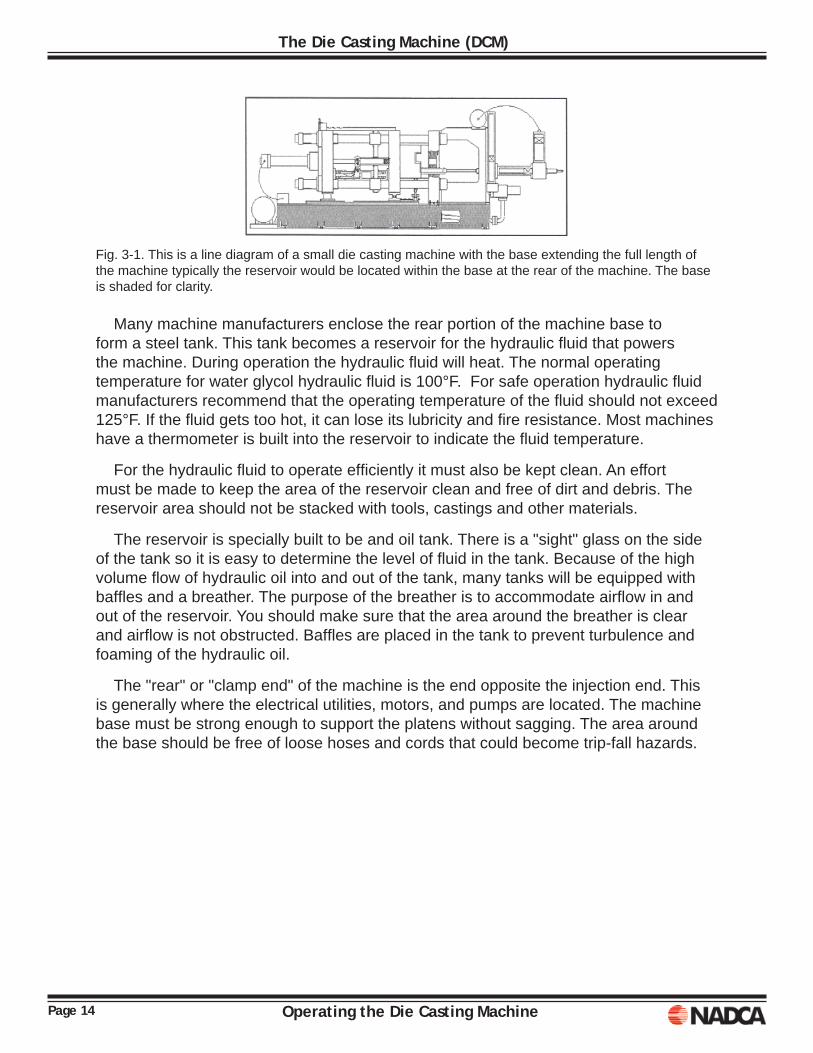
Fig. 3-1. This is a line diagram of a small die casting machine with the base extending the full length of the machine typically the reservoir would be located within the base at the rear of the machine. The base is shaded for clarity.
Many machine manufacturers enclose the rear portion of the machine base to form a steel tank. This tank becomes a reservoir for the hydraulic fl uid that powers the machine. During operation the hydraulic fl uid will heat. The normal operating temperature for water glycol hydraulic fl uid is 100°F. For safe operation hydraulic fl uid manufacturers recommend that the operating temperature of the fl uid should not exceed 125°F. If the fl uid gets too hot, it can lose its lubricity and fi re resistance. Most machines have a thermometer is built into the reservoir to indicate the fl uid temperature.
For the hydraulic fl uid to operate effi ciently it must also be kept clean. An effort must be made to keep the area of the reservoir clean and free of dirt and debris. The reservoir area should not be stacked with tools, castings and other materials.
The reservoir is specially built to be and oil tank. There is a "sight" glass on the side of the tank so it is easy to determine the level of fl uid in the tank. Because of the high volume fl ow of hydraulic oil into and out of the tank, many tanks will be equipped with baffl es and a breather. The purpose of the breather is to accommodate airfl ow in and out of the reservoir. You should make sure that the area around the breather is clear and airfl ow is not obstructed. Baffl es are placed in the tank to prevent turbulence and foaming of the hydraulic oil.
The "rear" or "clamp end" of the machine is the end opposite the injection end. This is generally where the electrical utilities, motors, and pumps are located. The machine base must be strong enough to support the platens without sagging. The area around the base should be free of loose hoses and cords that could become trip-fall hazards.
Page 15Operating the Die Casting Machine
The Die Casting Machine (DCM)
Platens
The platens are the three large plates that support the machine loads. They rest on the machine base. They are known as the Stationary platen, Moving platen, and Adjustable or Rear platen. Their functions are fairly straightforward. The Stationary platen, located at the "shot" end of the machine, holds the stationary die half. The shot end is mounted on the other side. The Moving platen is located between the Stationary and Rear platens. The moving or ejector half of the die is mounted to the moving platen. The Rear platen is located at the rear of the machine. The Moving and Rear platens are generally resting on "shoes" that slide on replaceable wear plates. Both the Moving and Rear platens move every cycle. The Moving platen slides back and forth to open and close the die. The Rear platen slides a little as the tie bars stretch. The Rear platen is also known as the Adjustable platen due to its movement to accommodate die height adjustment.
Fig. 3-2. Line diagram of a die casting machine with platens identifi ed and shaded for clarity.
The platens must be kept clean, particularly the die mounting surfaces of the moving and stationary platens. These must be cleaned every set-up to assure that the die parting lines are kept parallel to the machine platens and to assure there is good heat transfer from the die to the platens.
The surfaces of the Stationary and Moving platens in the die space will have Tee slots or tapped holes for clamping the die. Care must be taken during set-up and operation to make sure these features are not damaged.
Page 16 Operating the Die Casting Machine
The Die Casting Machine (DCM)
Fig.3-3 View of the stationary platen showing the Tee-slots and through hole for the cold chamber.
Fig. 3-4. View of a shot block.
The Stationary platen will have one or more holes machined through it. One hole is usually at the machine centerline and the other hole will be a position below the machine center. This will allow for two different die fi lling positions. Some machines will have a slot for an adapter that would allow multiple die fi lling positions. This is called a shot block or platen adapter.
Page 17Operating the Die Casting Machine
The Die Casting Machine (DCM)
The Stationary and moving platens may increase in temperature during operation. With hot chamber operation this may be enough to burn a person. The operator should be aware of this potential burn hazard. By its very nature, the Moving platen can become a strike hazard. Items attached to the Moving platen or items attached and projecting from the platens may be snag hazard. Care must be exercised around the Moving platen to make sure all guards are in place and properly mounted.
Tie Bars
Most machines have four tie bars. The tie bars are long, solid columns mounted through the four corners of the platens. They are used to orient and position the platens. The Moving platen actually slides along the tie bars. The size and strength of the tie bars determines the size of the machine. Every cycle the tie bars actually stretch to develop the force that is necessary to hold the die together against the force of injection. If the machine is improperly set-up or somehow a tie bar becomes excessively stretched, it is possible to break the tie bar.
Fig.3-5. Schematic diagram of a generic die casting machine with the tie bars and tie bar nuts identifi ed.
Toggle Linkage Mechanism
The Rear and Moving platens are connected to each other with the toggle linkage mechanism. The confi guration of this mechanism differs among machine manufacturers. Some linkages apply force at the four corners of the platens; others apply force along vertical or horizontal lines inside the tie bars. It takes a great deal of force to stretch the tie bars and lock the machine. If this were to be accomplished with a hydraulic cylinder, the cylinder required would be very large and move very slowly because of the large amount of oil that would be needed. Some older machines in the 1940's did have very large cylinders. Die casting machine engineers developed the toggle linkage to overcome the defi ciencies of using a large cylinder. The toggles act as levers and gain a mechanical advantage during die closing and locking. This allows the use of smaller closing cylinders that can operate at higher speeds.
Page 18 Operating the Die Casting Machine
The Die Casting Machine (DCM)
Fig. 3-6. Top fi gure shows toggle mechanism retracted, the machine/die would be open. The bottom fi gure shows the toggle mechanism extended, the machine/die would be closed.
Fig. 3-7. The toggle mechanism of a modern die casting machine located between the Moving and rear platens.
The toggle linkage area contains many pinch points that can be hazardous when the machine is operating. Guards should always be in place when the machine is operating or being set-up. If the toggle linkage area needs maintenance, the machine must be locked out and in a zero energy state (ZES) to prevent injury.
Page 19Operating the Die Casting Machine
The Die Casting Machine (DCM)
ELECTRICAL SYSTEM Motor and Control Panel
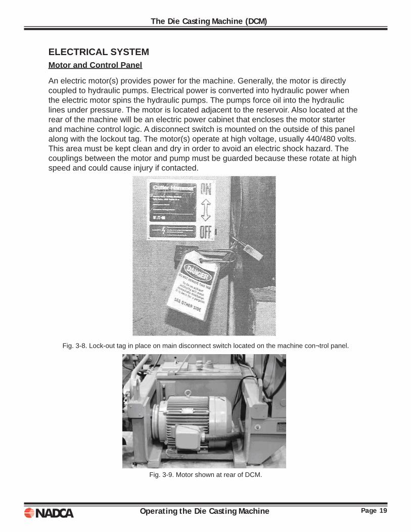
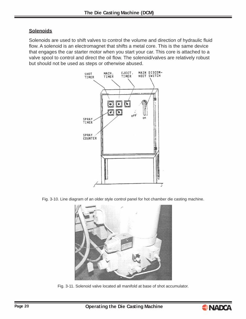
An electric motor(s) provides power for the machine. Generally, the motor is directly coupled to hydraulic pumps. Electrical power is converted into hydraulic power when the electric motor spins the hydraulic pumps. The pumps force oil into the hydraulic lines under pressure. The motor is located adjacent to the reservoir. Also located at the rear of the machine will be an electric power cabinet that encloses the motor starter and machine control logic. A disconnect switch is mounted on the outside of this panel along with the lockout tag. The motor(s) operate at high voltage, usually 440/480 volts. This area must be kept clean and dry in order to avoid an electric shock hazard. The couplings between the motor and pump must be guarded because these rotate at high speed and could cause injury if contacted.
Fig. 3-8. Lock-out tag in place on main disconnect switch located on the machine con¬trol panel.
Fig. 3-9. Motor shown at rear of DCM.
Page 20 Operating the Die Casting Machine
The Die Casting Machine (DCM)
Solenoids
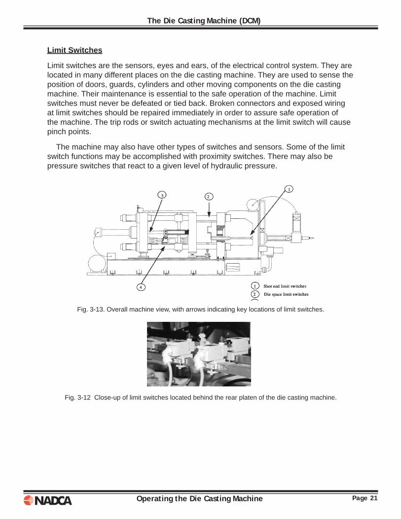
Solenoids are used to shift valves to control the volume and direction of hydraulic fl uid fl ow. A solenoid is an electromagnet that shifts a metal core. This is the same device that engages the car starter motor when you start your car. This core is attached to a valve spool to control and direct the oil fl ow. The solenoid/valves are relatively robust but should not be used as steps or otherwise abused.
Fig. 3-10. Line diagram of an older style control panel for hot chamber die casting machine.
Fig. 3-11. Solenoid valve located all manifold at base of shot accumulator.
Page 21Operating the Die Casting Machine
The Die Casting Machine (DCM)
Limit Switches
Limit switches are the sensors, eyes and ears, of the electrical control system. They are located in many different places on the die casting machine. They are used to sense the position of doors, guards, cylinders and other moving components on the die casting machine. Their maintenance is essential to the safe operation of the machine. Limit switches must never be defeated or tied back. Broken connectors and exposed wiring at limit switches should be repaired immediately in order to assure safe operation of the machine. The trip rods or switch actuating mechanisms at the limit switch will cause pinch points.
The machine may also have other types of switches and sensors. Some of the limit switch functions may be accomplished with proximity switches. There may also be pressure switches that react to a given level of hydraulic pressure.
Fig. 3-13. Overall machine view, with arrows indicating key locations of limit switches.
Fig. 3-12 Close-up of limit switches located behind the rear platen of the die casting machine.
Page 22 Operating the Die Casting Machine
The Die Casting Machine (DCM)
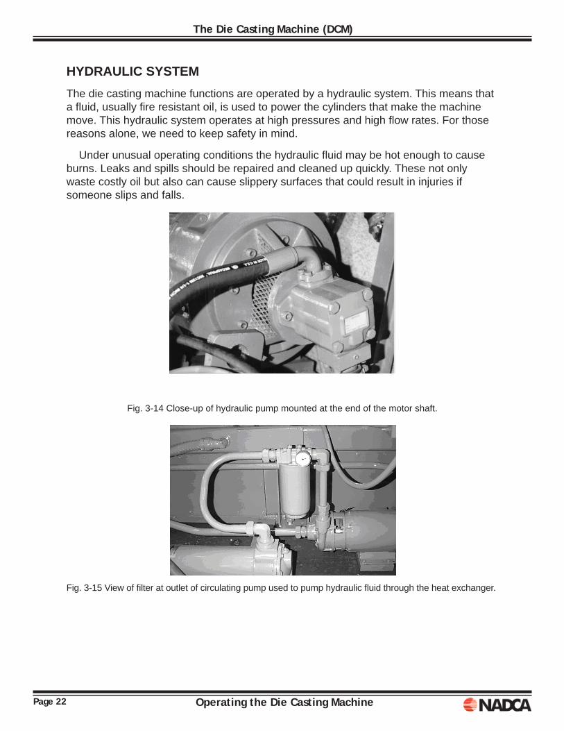
HYDRAULIC SYSTEM The die casting machine functions are operated by a hydraulic system. This means that a fl uid, usually fi re resistant oil, is used to power the cylinders that make the machine move. This hydraulic system operates at high pressures and high fl ow rates. For those reasons alone, we need to keep safety in mind.
Under unusual operating conditions the hydraulic fl uid may be hot enough to cause burns. Leaks and spills should be repaired and cleaned up quickly. These not only waste costly oil but also can cause slippery surfaces that could result in injuries if someone slips and falls.
Fig. 3-14 Close-up of hydraulic pump mounted at the end of the motor shaft.
Fig. 3-15 View of fi lter at outlet of circulating pump used to pump hydraulic fl uid through the heat exchanger.
Page 23Operating the Die Casting Machine
The Die Casting Machine (DCM)
Hydraulic Pumps
A die casting machine usually has a minimum of two hydraulic pumps. One pump is capable of providing oil at high pressures but in low volumes. A second pump would be capable of providing a high volume of oil at low pressures. For example, the pumping capabilities of a 400-ton machine may be 8 gallons per minute of 2000 PSI oil from the high pressure pump and 40 gallons per minute of 40 PSI oil from the low pressure pump. This type of pumping capability is used to solve the various demands of the die casting machine. The die close cylinder requires a large amount of oil to open and close the moving platen. Once the die faces close, only a small volume of high pressure oil is required to stretch the tie bars and lock the die. Just the act of closing requires the output of both pumps. (In cases where the output of both pumps is still too slow, an accumulator will be used to speed die closing.)
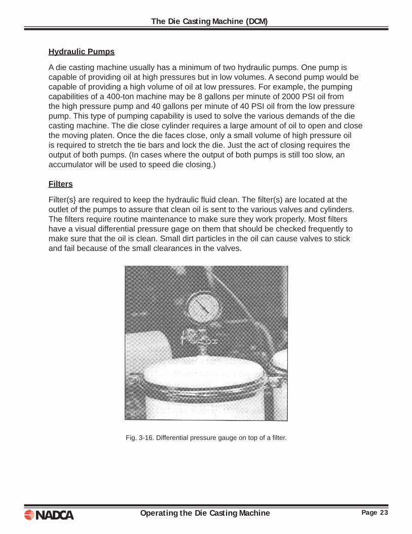
Filters
Filter(s} are required to keep the hydraulic fl uid clean. The fi lter(s) are located at the outlet of the pumps to assure that clean oil is sent to the various valves and cylinders. The fi lters require routine maintenance to make sure they work properly. Most fi lters have a visual differential pressure gage on them that should be checked frequently to make sure that the oil is clean. Small dirt particles in the oil can cause valves to stick and fail because of the small clearances in the valves.
Fig. 3-16. Differential pressure gauge on top of a fi lter.
Page 24 Operating the Die Casting Machine
The Die Casting Machine (DCM)
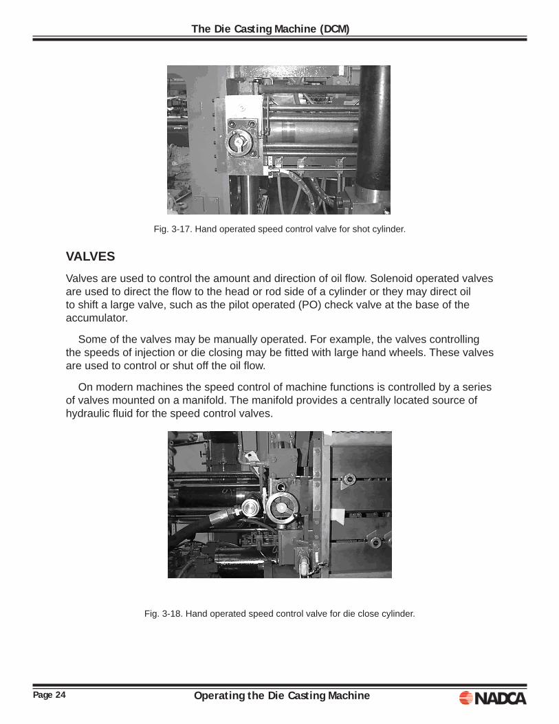
Fig. 3-17. Hand operated speed control valve for shot cylinder. VALVESValves are used to control the amount and direction of oil fl ow. Solenoid operated valves are used to direct the fl ow to the head or rod side of a cylinder or they may direct oil to shift a large valve, such as the pilot operated (PO) check valve at the base of the accumulator.
Some of the valves may be manually operated. For example, the valves controlling the speeds of injection or die closing may be fi tted with large hand wheels. These valves are used to control or shut off the oil fl ow.
On modern machines the speed control of machine functions is controlled by a series of valves mounted on a manifold. The manifold provides a centrally located source of hydraulic fl uid for the speed control valves.
Fig. 3-18. Hand operated speed control valve for die close cylinder.
Page 25Operating the Die Casting Machine
The Die Casting Machine (DCM)
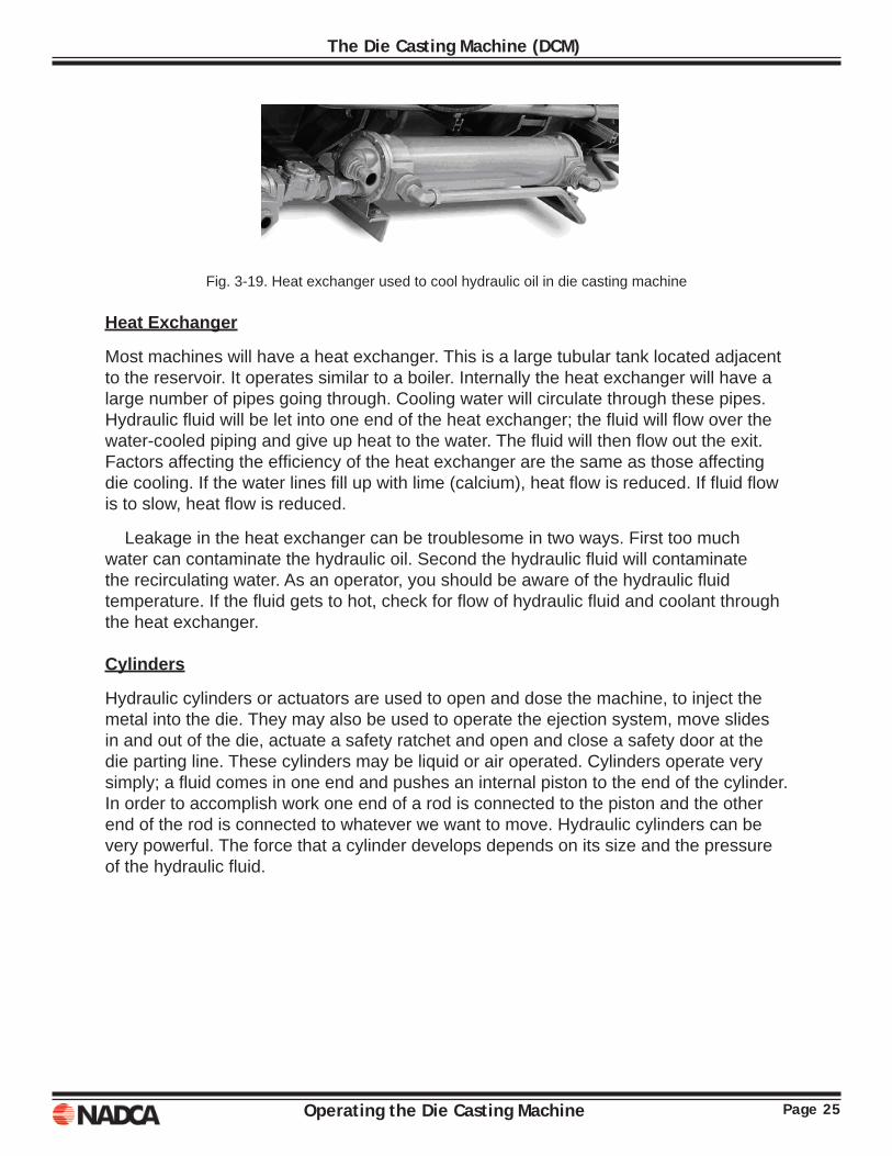
Fig. 3-19. Heat exchanger used to cool hydraulic oil in die casting machine
Heat Exchanger
Most machines will have a heat exchanger. This is a large tubular tank located adjacent to the reservoir. It operates similar to a boiler. Internally the heat exchanger will have a large number of pipes going through. Cooling water will circulate through these pipes. Hydraulic fl uid will be let into one end of the heat exchanger; the fl uid will fl ow over the water-cooled piping and give up heat to the water. The fl uid will then fl ow out the exit. Factors affecting the effi ciency of the heat exchanger are the same as those affecting die cooling. If the water lines fi ll up with lime (calcium), heat fl ow is reduced. If fl uid fl ow is to slow, heat fl ow is reduced.
Leakage in the heat exchanger can be troublesome in two ways. First too much water can contaminate the hydraulic oil. Second the hydraulic fl uid will contaminate the recirculating water. As an operator, you should be aware of the hydraulic fl uid temperature. If the fl uid gets to hot, check for fl ow of hydraulic fl uid and coolant through the heat exchanger.
Cylinders
Hydraulic cylinders or actuators are used to open and dose the machine, to inject the metal into the die. They may also be used to operate the ejection system, move slides in and out of the die, actuate a safety ratchet and open and close a safety door at the die parting line. These cylinders may be liquid or air operated. Cylinders operate very simply; a fl uid comes in one end and pushes an internal piston to the end of the cylinder. In order to accomplish work one end of a rod is connected to the piston and the other end of the rod is connected to whatever we want to move. Hydraulic cylinders can be very powerful. The force that a cylinder develops depends on its size and the pressure of the hydraulic fl uid.
Page 26 Operating the Die Casting Machine
The Die Casting Machine (DCM)
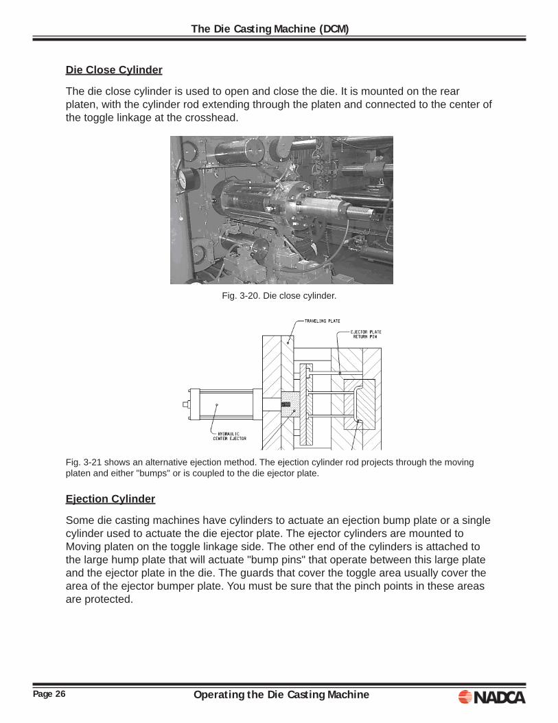
Die Close Cylinder
The die close cylinder is used to open and close the die. It is mounted on the rear platen, with the cylinder rod extending through the platen and connected to the center of the toggle linkage at the crosshead.
Fig. 3-20. Die close cylinder.
Fig. 3-21 shows an alternative ejection method. The ejection cylinder rod projects through the moving platen and either "bumps" or is coupled to the die ejector plate.
Ejection Cylinder
Some die casting machines have cylinders to actuate an ejection bump plate or a single cylinder used to actuate the die ejector plate. The ejector cylinders are mounted to Moving platen on the toggle linkage side. The other end of the cylinders is attached to the large hump plate that will actuate "bump pins" that operate between this large plate and the ejector plate in the die. The guards that cover the toggle area usually cover the area of the ejector bumper plate. You must be sure that the pinch points in these areas are protected.
Page 27Operating the Die Casting Machine
The Die Casting Machine (DCM)
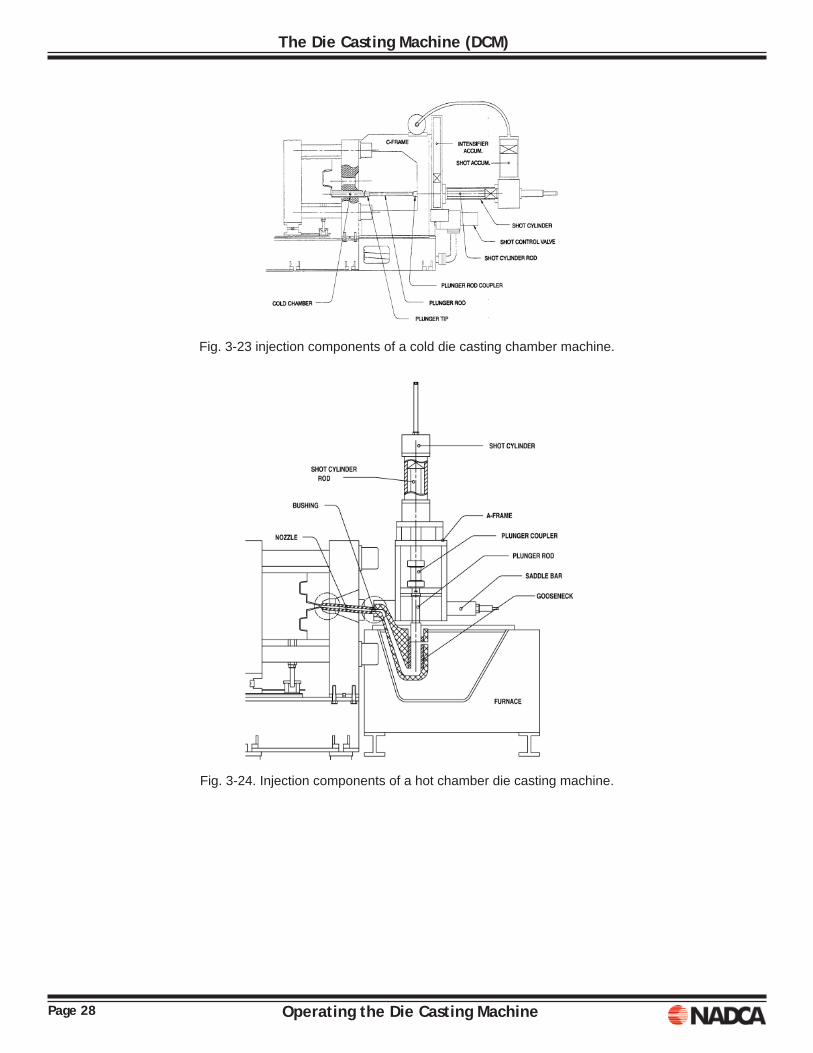
Shot Cylinder
On a cold chamber machine the cylinder rod is connected to a plunger that is located in the cold chamber. The shot cylinder is mounted to a "C" frame that is mounted to the stationary platen. Injection Components
The cold chamber components include the shot cylinder, plunger rod and tip, coupling and the cold chamber. Alignment of the chamber, tip and rod, and shot cylinder is critical to the effi cient operation of the injection system. The shot cylinder rod extends from the shot cylinder and is connected to the plunger rod with a coupling. Care must be taken to avoid damage to the cylinder rod. It is a precision-machined component that extends through a packing gland that seals the high pressure oil into the shot cylinder. This should not be used as a step or tool rest. In some cases the position and velocity transducers for the shot cylinder are machined into the cylinder rod. The plunger tip is usually made from a beryllium copper alloy in order to achieve fast cooling of the biscuit or plug at the end of the cold chamber. Proper cooling and temperature control of the tip is necessary to prevent metal from bypassing the tip and spitting out of the chamber. This can be hazardous. Sticking tips can also be a problem and proper training is necessary before one attempts to remove a stuck plunger.
For effi cient operation, care must be taken during set-up to assure that the shot cylinder and plunger are in proper alignment. This will assure a minimum of wear and operating problems.
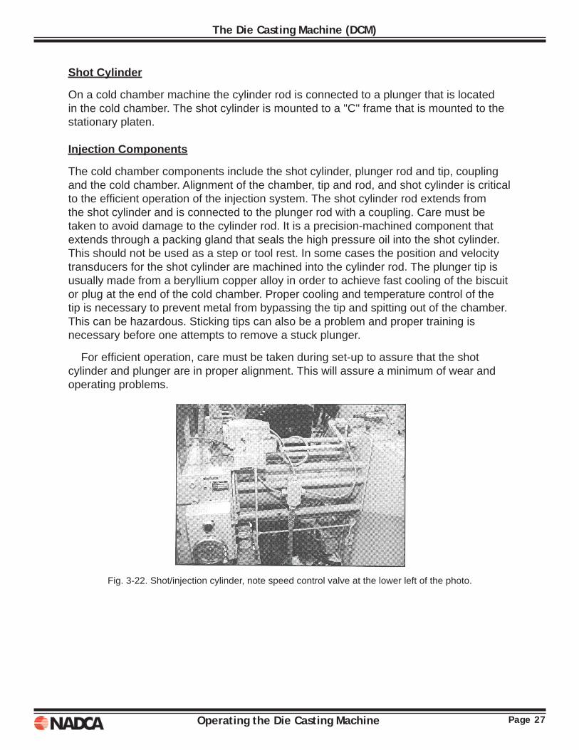
Fig. 3-22. Shot/injection cylinder, note speed control valve at the lower left of the photo.
Page 28 Operating the Die Casting Machine
The Die Casting Machine (DCM)
Fig. 3-23 injection components of a cold die casting chamber machine.
Fig. 3-24. Injection components of a hot chamber die casting machine.
Page 29Operating the Die Casting Machine
The Die Casting Machine (DCM)
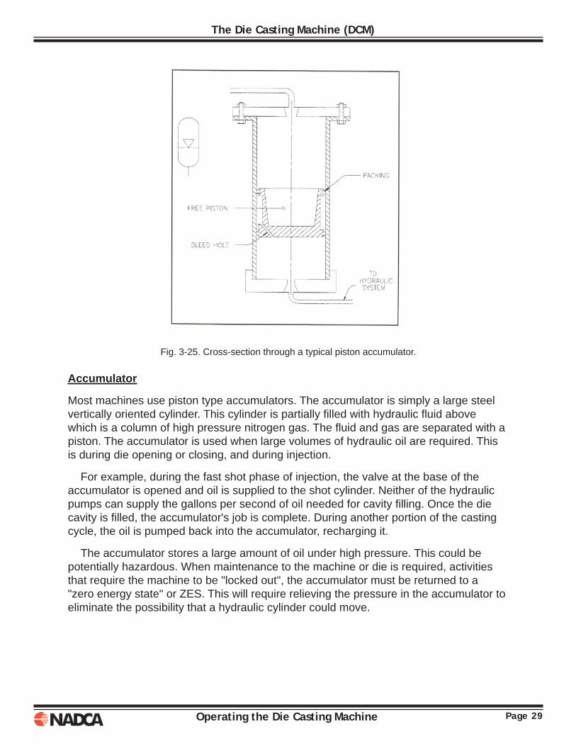
Fig. 3-25. Cross-section through a typical piston accumulator. Accumulator
Most machines use piston type accumulators. The accumulator is simply a large steel vertically oriented cylinder. This cylinder is partially fi lled with hydraulic fl uid above which is a column of high pressure nitrogen gas. The fl uid and gas are separated with a piston. The accumulator is used when large volumes of hydraulic oil are required. This is during die opening or closing, and during injection.
For example, during the fast shot phase of injection, the valve at the base of the accumulator is opened and oil is supplied to the shot cylinder. Neither of the hydraulic pumps can supply the gallons per second of oil needed for cavity fi lling. Once the die cavity is fi lled, the accumulator's job is complete. During another portion of the casting cycle, the oil is pumped back into the accumulator, recharging it.
The accumulator stores a large amount of oil under high pressure. This could be potentially hazardous. When maintenance to the machine or die is required, activities that require the machine to be "locked out", the accumulator must be returned to a "zero energy state" or ZES. This will require relieving the pressure in the accumulator to eliminate the possibility that a hydraulic cylinder could move.
Page 30 Operating the Die Casting Machine
The Die Casting Machine (DCM)
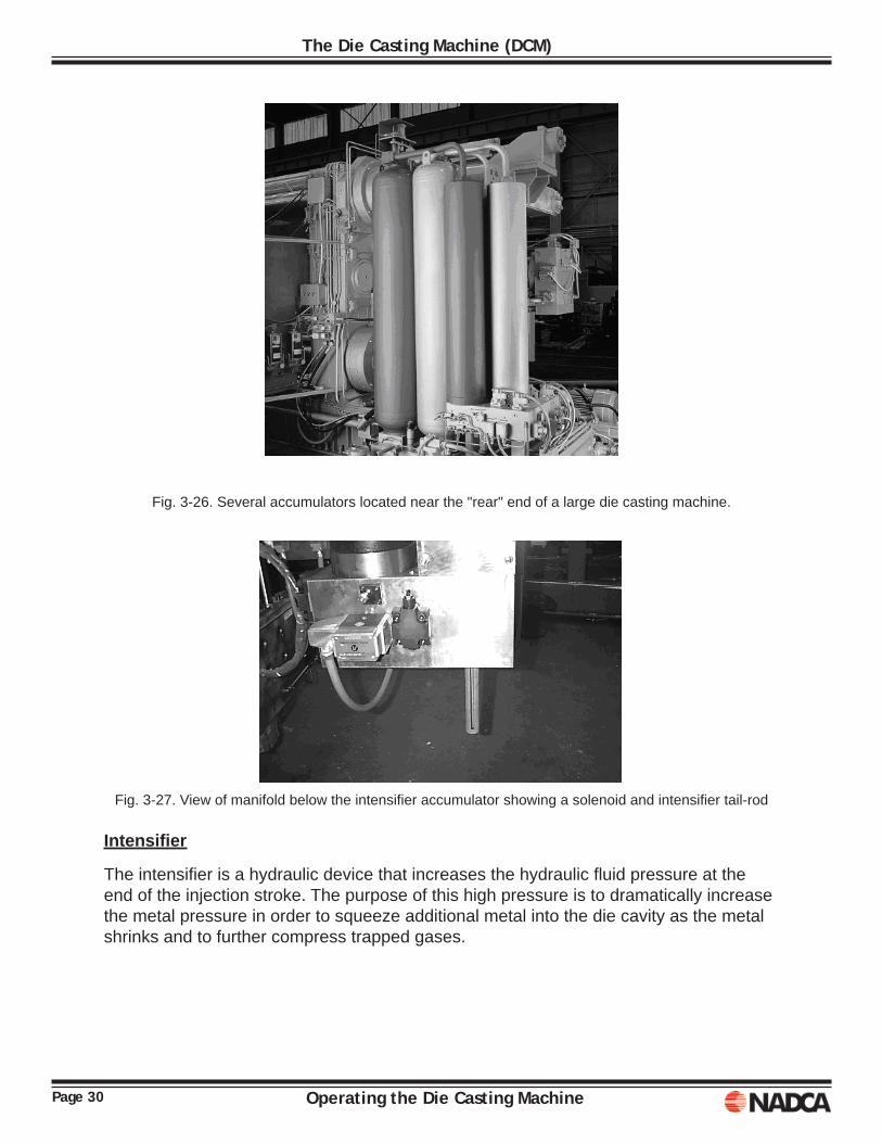
Fig. 3-26. Several accumulators located near the "rear" end of a large die casting machine.
Fig. 3-27. View of manifold below the intensifi er accumulator showing a solenoid and intensifi er tail-rod
Intensifi er
The intensifi er is a hydraulic device that increases the hydraulic fl uid pressure at the end of the injection stroke. The purpose of this high pressure is to dramatically increase the metal pressure in order to squeeze additional metal into the die cavity as the metal shrinks and to further compress trapped gases.
Page 31Operating the Die Casting Machine
The Die Casting Machine (DCM)
SAFETY COMPONENTSThe current safety standard for die casting machines shipped for use in North America is NADCA B152.1-2006. This standard details the safety devices required on the DCM, to make it acceptable for use in North America. This safety standard applies to new DCM’s shipped after its implementation date and to existing installations within the implementation period allowed by the standard. This standard is available for no charge at the NADCA website “diecasting.org”.
Die casting safety and DCM safe operation are extensive topics. Chapter 10 in this manual addresses die casting safety from a general point of view. The NADCA course EC908, Die Casting Machine Safety is recommended for anyone working with or in the DCM environment.

Page 32 Operating the Die Casting Machine
The Die Casting Machine (DCM)
Operating the Die Casting Machine Page 33
Chapter 4MACHINE, CLOSING AND INJECTION
DCM closing and injection are two of the most important machine functions. This chapter will discuss the conditions that must be met before the machine will close the die and how the tie bars work to develop the force necessary to hold the machine closed against the force of injection. Then the conditions necessary for injection are discussed followed by an explanation of the injection sequence and shot profi le. CLOSING
Before the DCM will close, a number of conditions must be satisfi ed. The following list of conditions may not be complete for every particular circumstance. The actual list of conditions depends on the age and manufacturer of the particular DC machine that is being used. The DC machine operator must take responsibility to determine accurately if this list is complete or if additional conditions must be met. As each cycle is initiated, the machine logic will check limit switches and sensors to determine if the conditions for closing are satisfi ed.
Conditions at the DCM
1. The moving platen must be in the fully open position. The die closing cylin¬der must be fully retracted. If this is not the case, the DC machine must be fully opened manually.
2. The hydraulic ejection cylinder(s) must be retracted. 3. The injection cylinder is fully retracted, in the ready to cast position. 4. Safety doors and barriers are in place preventing access to the die space. 5. Guards are in place over and around the toggle linkage. 6. The pawl is engaged in the safety ratchet if the machine is so equipped.
Page 34 Operating the Die Casting Machine
Machine, Closing and Injection
Conditions at the DC Die
1. For dies equipped with hydraulically actuated cores; cores mounted to the moving/ ejector die half must be "in" or in the ready to cast position, cores mounted to the stationary or cover die half must be "out" or withdrawn.
2. For dies equipped with hydraulic ejection coupled to the ejector plate, the ejector plate must be returned, in the ready to cast position.
3. For dies employing the use of "cast-in" inserts, the inserts must be loaded in the die.
Once all the machine/die closure conditions have been satisfi ed, and upon receipt of the cycle start signal, the safety pawl is withdrawn and the machine can begin closing. The machine will close rapidly, but under low pressure. The speed of die closing can be controlled by opening or closing a throttle valve; or if cartridge valves are used, by programming the logic controller. A properly set machine will close using low pressure hydraulic oil. In case an obstruction is encountered, the machine will stop, not having enough power to overcome the obstruction and cause damage. The setting is only good to prevent damage to tooling and equipment and should not be considered a personnel safety device. A limit switch setting should determine the transition from low to high pressure. This should be 'within 0.030" of the die faces meeting. High pressure oil is used to close the die, stretch the tie bars and lock the die.
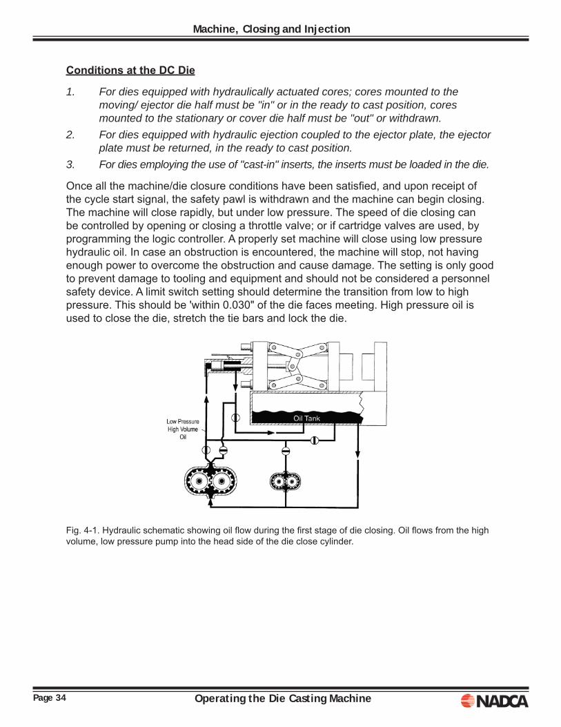
Fig. 4-1. Hydraulic schematic showing oil fl ow during the fi rst stage of die closing. Oil fl ows from the high volume, low pressure pump into the head side of the die close cylinder.
Page 35Operating the Die Casting Machine
Machine, Closing and Injection
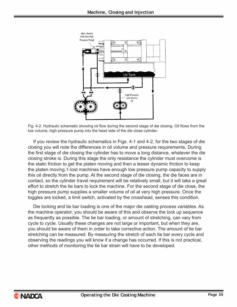
Fig. 4-2. Hydraulic schematic showing oil fl ow during the second stage of die closing. Oil fl ows from the low volume, high pressure pump into the head side of the die close cylinder.
If you review the hydraulic schematics in Figs. 4-1 and 4-2, for the two stages of die closing you will note the differences in oil volume and pressure requirements. During the fi rst stage of die closing the cylinder has to move a long distance, whatever the die closing stroke is. During this stage the only resistance the cylinder must overcome is the static friction to get the platen moving and then a lesser dynamic friction to keep the platen moving.1-Iost machines have enough low pressure pump capacity to supply this oil directly from the pump. At the second stage of die closing, the die faces are in contact, so the cylinder travel requirement will be relatively small, but it will take a great effort to stretch the tie bars to lock the machine. For the second stage of die close, the high pressure pump supplies a smaller volume of oil at very high pressure. Once the toggles are locked, a limit switch, activated by the crosshead, senses this condition.
Die locking and tie bar loading is one of the major die casting process variables. As the machine operator, you should be aware of this and observe the lock up sequence as frequently as possible. The tie bar loading, or amount of stretching, can vary from cycle to cycle. Usually these changes are not large or important, but when they are, you should be aware of them in order to take corrective action. The amount of tie bar stretching can be measured. By measuring the stretch of each tie bar every cycle and observing the readings you will know if a change has occurred. If this is not practical, other methods of monitoring the tie bar strain will have to be developed.
Page 36 Operating the Die Casting Machine
Machine, Closing and Injection
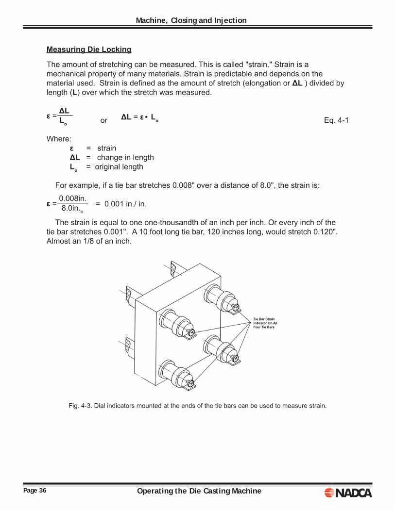
Measuring Die Locking
The amount of stretching can be measured. This is called "strain." Strain is a mechanical property of many materials. Strain is predictable and depends on the material used. Strain is defi ned as the amount of stretch (elongation or ΔL ) divided by length (L) over which the stretch was measured.
or Eq. 4-1
Where: ε = strain ΔL = change in length Lo = original length
For example, if a tie bar stretches 0.008" over a distance of 8.0", the strain is: = 0.001 in./ in.
The strain is equal to one one-thousandth of an inch per inch. Or every inch of the tie bar stretches 0.001". A 10 foot long tie bar, 120 inches long, would stretch 0.120". Almost an 1/8 of an inch.
Fig. 4-3. Dial indicators mounted at the ends of the tie bars can be used to measure strain.
ε = ΔL
——
LoΔL = ε• Lo
ε = 0.008in.
————
8.0in.o
Page 37Operating the Die Casting Machine
Machine, Closing and Injection
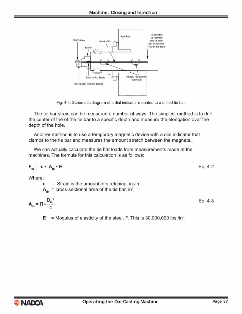
Fig. 4-4. Schematic diagram of a dial indicator mounted to a drilled tie bar.
The tie bar strain can be measured a number of ways. The simplest method is to drill the center of the of the tie bar to a specifi c depth and measure the elongation over the depth of the hole.
Another method is to use a temporary magnetic device with a dial indicator that clamps to the tie bar and measures the amount stretch between the magnets..
We can actually calculate the tie bar loads from measurements made at the machines. The formula for this calculation is as follows:
Ftb = ε • Atb • E Eq. 4-2
Where: ε = Strain is the amount of stretching, in./in. Atb = cross-sectional area of the tie bar, in2.
Eq. 4-3
E = Modulus of elasticity of the steel, F. This is 30,000,000 lbs./in2.
Atb = П•Dtb
2
——
4

Page 38 Operating the Die Casting Machine
Machine, Closing and Injection
Calculate Force/Load
Remember, strain is the "unit elongation", the amount of stretching for each inch of measured length. If the dial indicator reads 0.004 inches, over a measured length of 8.0 inches, the strain (ε) is 0.0005 inches.
Example: A machine with 4 inch diameter tie bars has a measured strain of 0.0005 in./in. What is the load/force on the tie bar?
Answer: F = ε • A • E ε = 0.0005 in./in.
F = ε • A •E = (0.0005 in./in.) • (12.57 in.2) • (30,000,000 lbs./in2) F = 188,550 lbs. or 94.3 tons
This would be equivalent to a 400 Ton DCM, about 100 tons per tie bar.
Exercise: The 400 Ton DCM in the previous example has tie bars that are 12 feet long. Prior to start-up you noticed fl ash sticking to the leader pin on the top of the die opposite the operator. You removed the fl ash but were surprised to fi nd it 0.015 inches thick. Could this damage the DCM or die? Explain.
ε = Measurement
= 0.004in.
= 0.0005in./in.
——————– ———–
length 8.0in.
A = П•D2
= 3.1416•(4in.)2
= 12.57in.2
—– ——–
4 4
Page 39Operating the Die Casting Machine
Machine, Closing and Injection
Changes to Die Locking
As noted previously, die locking/tie bar strain is an important process variable and you as the operator should be continually aware of how the die lock is behaving. Under normal operating conditions the machine cycle will have a particular rhythm to it. The normal cycle will have various noises, such the sprayers, the shot and the hydraulic pumps and motors. You should be aware when changes to this normal cycle occur, be aware of the exceptions. In the case of die locking, is the machine slowing down and straining more to lock the die? Has the machine sped up and is it locking with less effort? Is the machine straining and twisting, or bending? Is the machine "popping" or jumping when it unlocks? Machine locking and unlocking should be fl uid movement with a hesitation when the machine locks and stretches the tie bars.
The objective of the die is to maintain a consistent and uniform lock, straining the tie bars uniformly. If the die lock changes during production you should try to determine why the change occurred and correct the problem. There are several common causes for the die lock changing. They are:
o Temperature o Flash o Loose fi ttings
As the die heats up to operating temperature, it expands. This means the shut height dimension will get longer. As the die gets bigger, it will be more and more diffi cult for the machine to lock up. When this occurs, you will have to open the shut height and adjust for the larger die.
As with the die, during production the machine also warms up. It is possible that the tie bars could increase in temperature by 20-30°F. This will cause the tie bars to expand (get longer). If this happens the lock will get looser. The shut height will have to reduce to tighten the lock.
Flash stuck to the die faces will make the die thicker. This is similar to the die expanding due to heat, except it can be more of a problem. First, changes due to fl ash are usually greater than expansion. Second, the fl ash is not uniform and causes a load imbalance. Excessive fl ash has been responsible for a large number of broken tie bars.
As the machine locks, it squeezes the die faces together and pushes against the stationary and rear platens. The platens in turn push on the tie bar nuts. The tie bar nuts grip and stretch the tie bars. If the nuts are loose and can rotate on their thread, the die lock can change. Each nut will have a hold down device to prevent the nut from turning. You should make sure on a daily basis that the nuts are secure. This should be part of your start up machine inspection.
Page 40 Operating the Die Casting Machine
Machine, Closing and Injection
INJECTION
Before injection will occur a number of process and safety conditions must be satisfi ed.
o The die must be locked. o The plunger must be retracted in the ready to cast position. o All safety doors and barriers must be in place. o Plunger tip has been lubed and is cooling properly.
The injection sequence begins when metal is poured into the cold chamber. The metal should be dipped/pumped from the holding furnace and transferred to the cold chamber as quickly as possible, to minimize heat loss and with as little turbulence as possible. Agitation at this time would only add to oxidation problems.
The alloy should be poured into the cold chamber quickly, but without agitation. It has been estimated that the heat lost during alloy transfer could be as much as 20-30°F per second. Then the shot is initiated. The wave formation, in the cold chamber, during slow shot is very important. A wave forms as the alloy is poured into the sleeve. The alloy quickly runs down to the parting line of the die and is refl ected back to the pour hole. The ideal time to start the shot is when the wave arrives back at the shot hole and is refl ected toward the biscuit block. An alternative is to pour slowly and try not to start a wave.
During injection a number of important process characteristics are executed, characteristics that have a great infl uence on the casting quality. These characteristics (or variables) are:
o Slow velocity past pour hole o Critical slow shot velocity (CSS) o Slow/Fast transition point o Fast shot speed/fi ll time o Static pressure o Intensifi cation start time, ramp time and pressure
Many machines have limited injection capability. For example, many hot chamber machines only have a fast shot without intensifi cation. A few will have a slow and fast shot. Most cold chamber machines have a slow and fast shot capability with some capability for increasing hydraulic force at the end of cavity fi lling, called intensifi cation or pre-fi ll. The example calculations that follow could be used to construct a theoretical shot velocity profi le.
Pour Hole VelocityFor purpose of this discussion the pour hole velocity will be defi ned as the portion of the
injection sequence when the plunger travels from its start position to past the pour hole. Plunger speed during this fi rst step is very slow. The objective is to travel past the pour hole without splashing metal out of the pour hole and minimizing turbulence in the shot sleeve. Pour hole speeds are generally in the range of 3-7 inches per second (0.8-0.18 ms).
Page 41Operating the Die Casting Machine
Machine, Closing and Injection
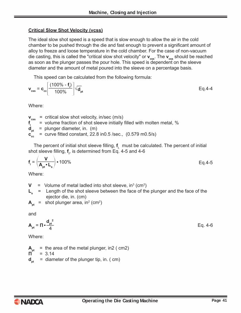
Critical Slow Shot Velocity (vcss)
The ideal slow shot speed is a speed that is slow enough to allow the air in the cold chamber to be pushed through the die and fast enough to prevent a signifi cant amount of alloy to freeze and loose temperature in the cold chamber. For the case of non-vacuum die casting, this is called the "critical slow shot velocity" or vcss. The vcss should be reached as soon as the plunger passes the pour hole. This speed is dependent on the sleeve diameter and the amount of metal poured into the sleeve on a percentage basis.
This speed can be calculated from the following formula:
Eq.4-4
Where:
vcss = critical slow shot velocity, in/sec (m/s) fi = volume fraction of shot sleeve initially fi lled with molten metal, % dpt = plunger diameter, in. (m)ccc = curve fi tted constant, 22.8 in0.5 /sec., (0.579 m0.5/s)
The percent of initial shot sleeve fi lling, fi, must be calculated. The percent of initial shot sleeve fi lling, fi, is determined from Eq. 4-5 and 4-6
Eq.4-5
Where:
V = Volume of metal ladled into shot sleeve, in3 (cm3) Ls = Length of the shot sleeve between the face of the plunger and the face of the
ejector die, in. (cm) Apt = shot plunger area, in2 (cm2)
and Eq. 4-6
Where: Apt = the area of the metal plunger, in2 ( cm2)Π = 3.14 dpt = diameter of the plunger tip, in. ( cm)
vcss = cccq(100% - fi)r√
—————
—
100% dpt
fi = o V p•100%
———–
Apt•Ls
Apt = П•dpt
2
—–
4
Page 42 Operating the Die Casting Machine
Machine, Closing and Injection
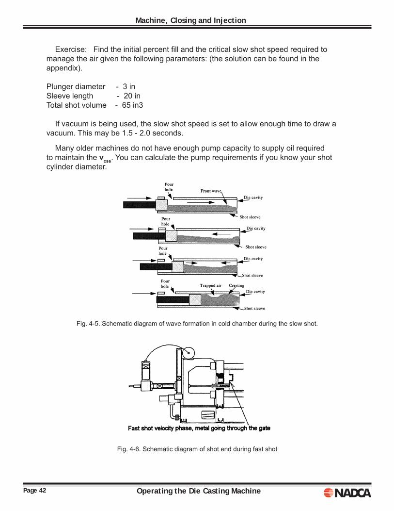
Exercise: Find the initial percent fi ll and the critical slow shot speed required to manage the air given the following parameters: (the solution can be found in the appendix). Plunger diameter - 3 in Sleeve length - 20 in Total shot volume - 65 in3
If vacuum is being used, the slow shot speed is set to allow enough time to draw a vacuum. This may be 1.5 - 2.0 seconds.
Many older machines do not have enough pump capacity to supply oil required to maintain the vcss. You can calculate the pump requirements if you know your shot cylinder diameter.
Fig. 4-5. Schematic diagram of wave formation in cold chamber during the slow shot.
Fig. 4-6. Schematic diagram of shot end during fast shot
Page 43Operating the Die Casting Machine
Machine, Closing and Injection
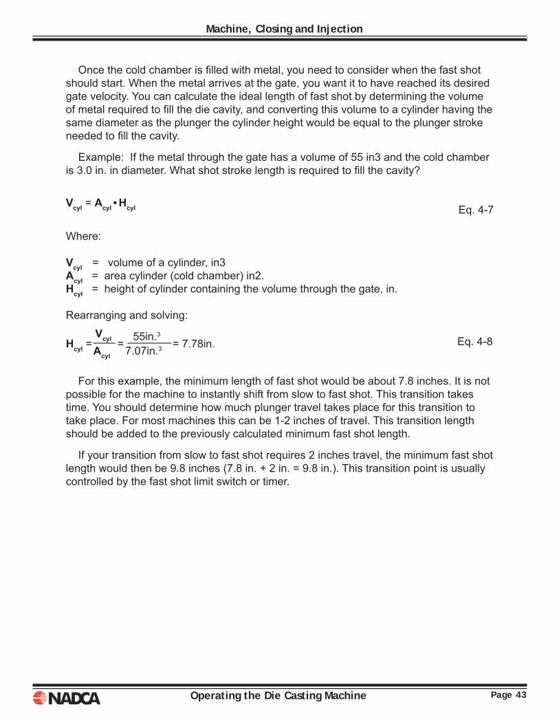
Once the cold chamber is fi lled with metal, you need to consider when the fast shot should start. When the metal arrives at the gate, you want it to have reached its desired gate velocity. You can calculate the ideal length of fast shot by determining the volume of metal required to fi ll the die cavity, and converting this volume to a cylinder having the same diameter as the plunger the cylinder height would be equal to the plunger stroke needed to fi ll the cavity.
Example: If the metal through the gate has a volume of 55 in3 and the cold chamber is 3.0 in. in diameter. What shot stroke length is required to fi ll the cavity?
Eq. 4-7
Where:
Vcyl = volume of a cylinder, in3Acyl = area cylinder (cold chamber) in2. Hcyl = height of cylinder containing the volume through the gate, in.
Rearranging and solving: Eq. 4-8
For this example, the minimum length of fast shot would be about 7.8 inches. It is not possible for the machine to instantly shift from slow to fast shot. This transition takes time. You should determine how much plunger travel takes place for this transition to take place. For most machines this can be 1-2 inches of travel. This transition length should be added to the previously calculated minimum fast shot length.
If your transition from slow to fast shot requires 2 inches travel, the minimum fast shot length would then be 9.8 inches (7.8 in. + 2 in. = 9.8 in.). This transition point is usually controlled by the fast shot limit switch or timer.
Vcyl = Acyl•Hcyl
Hcyl = Vcyl =
55in.3 = 7.78in.
—— ————
Acyl 7.07in.3
Page 44 Operating the Die Casting Machine
Machine, Closing and Injection
Fast Shot Velocity
The fast velocity/shot speed is one of the most important process variables. This speed will determine the gate velocity and the cavity fi ll time. When the die is engineered, a lot of effort goes into determining the best gating, both gate size and fl ow pattern. This is based on the best estimate of a maximum allowable time to fi ll the die cavity and achieving atomization of the metal during fi lling. The calculation of cavity fi ll time is based on the casting geometry (mostly wall thickness) and die and metal temperatures. When a cavity fi ll time is calculated, this is the best estimate of the maximum time available to make an acceptable casting. This is an estimate or starting point that is then refi ned by experience. Fast shot speed is very important, since only one speed will give the best initial combination of gate velocity and fi ll time. The relationship between gate velocity, fi ll time and fast shot speed is as follows:
The die casting machine pumps the metal at a given fi ll rate, it pumps "Q" cubic inches of metal in a second. In fact, the shot end of a machine is rated by its maximum pumping capacity or fi lling rate for a give plunger size. The pumping rate for a particular job is determined by multiplying the plunger area times the plunger speed, or
Eq. 4-9
Where:Q = fl ow rate of metal into the cavity, in3/sec.Apt = area of plunger tip, in2.Vpt = velocity of plunger, in./sec.
Example: Given a 3 inch diameter plunger traveling at a fast shot speed of 120 inches per second, what is its fi lling rate?
Once the fi lling rate or pumping capacity for a given plunger diameter and plunger speed is known, you can determine the gate velocity and fi ll time straight away.
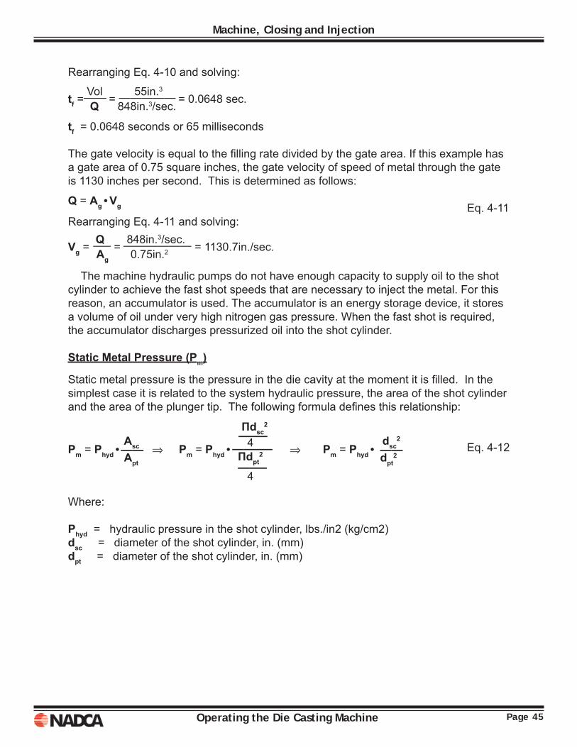
The fi ll time is equal to the volume of the metal through the gate (casting and overfl ows) divided by the fi lling rate. Eq. 4-10
In this example the casting and overfl ow volume was given as 55 cubic inches and fl ow rate at 848 in3/sec. The fi ll time can be calculated as follows:
Q = Apt•Vpt
Q = П•d2
•V = 3.1416•(3in.)2
•120in./sec. = 848in.3/sec.
——– ——————–
4 4
Q = Vol
——
tf
Page 45Operating the Die Casting Machine
Machine, Closing and Injection
Rearranging Eq. 4-10 and solving:
tf = 0.0648 seconds or 65 milliseconds
The gate velocity is equal to the fi lling rate divided by the gate area. If this example has a gate area of 0.75 square inches, the gate velocity of speed of metal through the gate is 1130 inches per second. This is determined as follows:
Eq. 4-11Rearranging Eq. 4-11 and solving:
The machine hydraulic pumps do not have enough capacity to supply oil to the shot cylinder to achieve the fast shot speeds that are necessary to inject the metal. For this reason, an accumulator is used. The accumulator is an energy storage device, it stores a volume of oil under very high nitrogen gas pressure. When the fast shot is required, the accumulator discharges pressurized oil into the shot cylinder.
Static Metal Pressure (Pm)
Static metal pressure is the pressure in the die cavity at the moment it is fi lled. In the simplest case it is related to the system hydraulic pressure, the area of the shot cylinder and the area of the plunger tip. The following formula defi nes this relationship:
Eq. 4-12
Where:
Phyd = hydraulic pressure in the shot cylinder, lbs./in2 (kg/cm2)dsc = diameter of the shot cylinder, in. (mm)dpt = diameter of the shot cylinder, in. (mm)
tf = Vol
= 55in.3
= 0.0648 sec.
—— —————
Q 848in.3/sec.
Q = Ag•Vg
Vg = Q =
848in.3/sec. = 1130.7in./sec.
—– ——————
Ag 0.75in.2
Pm = Phyd• Asc ⇒ Pm = Phyd•
Пdsc2
⇒ Pm = Phyd• dsc
2
——
——–
——
Apt
4
dpt2
———–
Пdpt2
——–
4
Page 46 Operating the Die Casting Machine
Machine, Closing and Injection
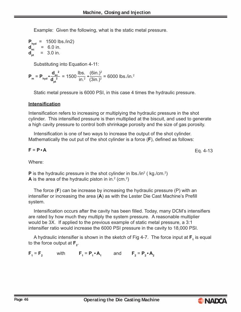
Example: Given the following, what is the static metal pressure.
Phyd = 1500 lbs./in2)dsc = 6.0 in. dpt = 3.0 in.
Substituting into Equation 4-11:
Static metal pressure is 6000 PSI, in this case 4 times the hydraulic pressure.
Intensifi cation
Intensifi cation refers to increasing or multiplying the hydraulic pressure in the shot cylinder. This intensifi ed pressure is then multiplied at the biscuit, and used to generate a high cavity pressure to control both shrinkage porosity and the size of gas porosity.
Intensifi cation is one of two ways to increase the output of the shot cylinder. Mathematically the out put of the shot cylinder is a force (F), defi ned as follows:
Eq. 4-13
Where:
P is the hydraulic pressure in the shot cylinder in lbs./in2 ( kg./cm.2)A is the area of the hydraulic piston in in.2 (cm.2)
The force (F) can be increase by increasing the hydraulic pressure (P) with an intensifi er or increasing the area (A) as with the Lester Die Cast Machine’s Prefi ll system.
Intensifi cation occurs after the cavity has been fi lled. Today, many DCM’s intensifi ers are rated by how much they multiply the system pressure. A reasonable multiplier would be 3X. If applied to the previous example of static metal pressure, a 3:1 intensifi er ratio would increase the 6000 PSI pressure in the cavity to 18,000 PSI.
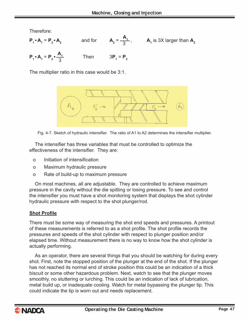
A hydraulic intensifi er is shown in the sketch of Fig 4-7. The force input at F1 is equal to the force output at F2.
Pm = Phyd• dsc
2
= 1500 lbs.
•(6in.)2
= 6000 lbs./in.2
—— ––– ——–
dpt2 in.2 (3in.)2
F = P•A
F1 = F2 with F1 = P1•A1 and F2 = P2•A2
Page 47Operating the Die Casting Machine
Machine, Closing and Injection
Therefore:
The multiplier ratio in this case would be 3:1.
Fig. 4-7. Sketch of hydraulic intensifi er. The ratio of A1 to A2 determines the intensifi er multiplier.
The intensifi er has three variables that must be controlled to optimize the effectiveness of the intensifi er. They are:
o Initiation of intensifi cationo Maximum hydraulic pressureo Rate of build-up to maximum pressure
On most machines, all are adjustable. They are controlled to achieve maximum pressure in the cavity without the die spitting or losing pressure. To see and control the intensifi er you must have a shot monitoring system that displays the shot cylinder hydraulic pressure with respect to the shot plunger/rod.
Shot Profi le
There must be some way of measuring the shot end speeds and pressures. A printout of these measurements is referred to as a shot profi le. The shot profi le records the pressures and speeds of the shot cylinder with respect to plunger position and/or elapsed time. Without measurement there is no way to know how the shot cylinder is actually performing.
As an operator, there are several things that you should be watching for during every shot. First, note the stopped position of the plunger at the end of the shot. If the plunger has not reached its normal end of stroke position this could be an indication of a thick biscuit or some other hazardous problem. Next, watch to see that the plunger moves smoothly, no stuttering or lurching. This could be an indication of lack of lubrication, metal build up, or inadequate cooling. Watch for metal bypassing the plunger tip. This could indicate the tip is worn out and needs replacement.
P1•A1 = P2•A2 and for A2 = A1 , A1 is 3X larger than A2
——
3
P1•A1 = P2• A1 Then 3P1 = P2
—–
3
Page 48 Operating the Die Casting Machine
Machine, Closing and Injection
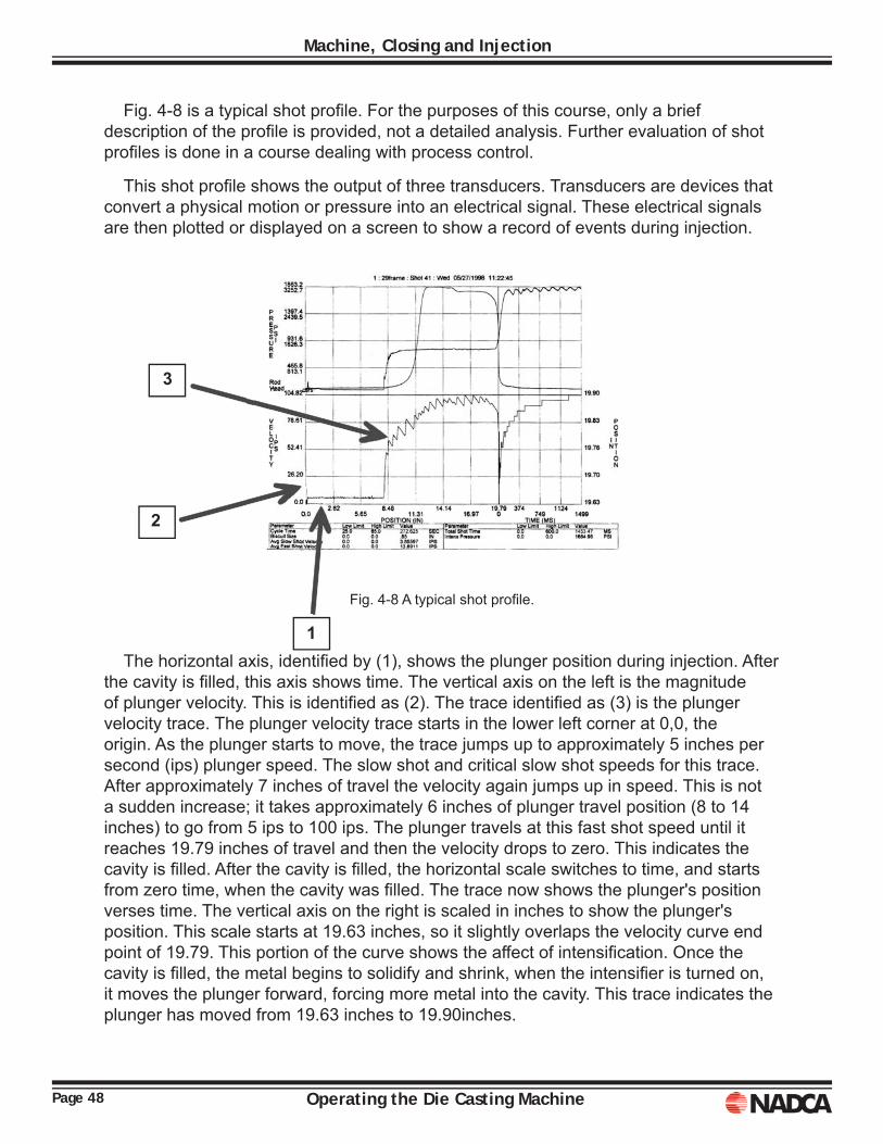
Fig. 4-8 is a typical shot profi le. For the purposes of this course, only a brief description of the profi le is provided, not a detailed analysis. Further evaluation of shot profi les is done in a course dealing with process control.
This shot profi le shows the output of three transducers. Transducers are devices that convert a physical motion or pressure into an electrical signal. These electrical signals are then plotted or displayed on a screen to show a record of events during injection.
Fig. 4-8 A typical shot profi le.
The horizontal axis, identifi ed by (1), shows the plunger position during injection. After the cavity is fi lled, this axis shows time. The vertical axis on the left is the magnitude of plunger velocity. This is identifi ed as (2). The trace identifi ed as (3) is the plunger velocity trace. The plunger velocity trace starts in the lower left corner at 0,0, the origin. As the plunger starts to move, the trace jumps up to approximately 5 inches per second (ips) plunger speed. The slow shot and critical slow shot speeds for this trace. After approximately 7 inches of travel the velocity again jumps up in speed. This is not a sudden increase; it takes approximately 6 inches of plunger travel position (8 to 14 inches) to go from 5 ips to 100 ips. The plunger travels at this fast shot speed until it reaches 19.79 inches of travel and then the velocity drops to zero. This indicates the cavity is fi lled. After the cavity is fi lled, the horizontal scale switches to time, and starts from zero time, when the cavity was fi lled. The trace now shows the plunger's position verses time. The vertical axis on the right is scaled in inches to show the plunger's position. This scale starts at 19.63 inches, so it slightly overlaps the velocity curve end point of 19.79. This portion of the curve shows the affect of intensifi cation. Once the cavity is fi lled, the metal begins to solidify and shrink, when the intensifi er is turned on, it moves the plunger forward, forcing more metal into the cavity. This trace indicates the plunger has moved from 19.63 inches to 19.90inches.
3
2
1
Page 49Operating the Die Casting Machine
Machine, Closing and Injection
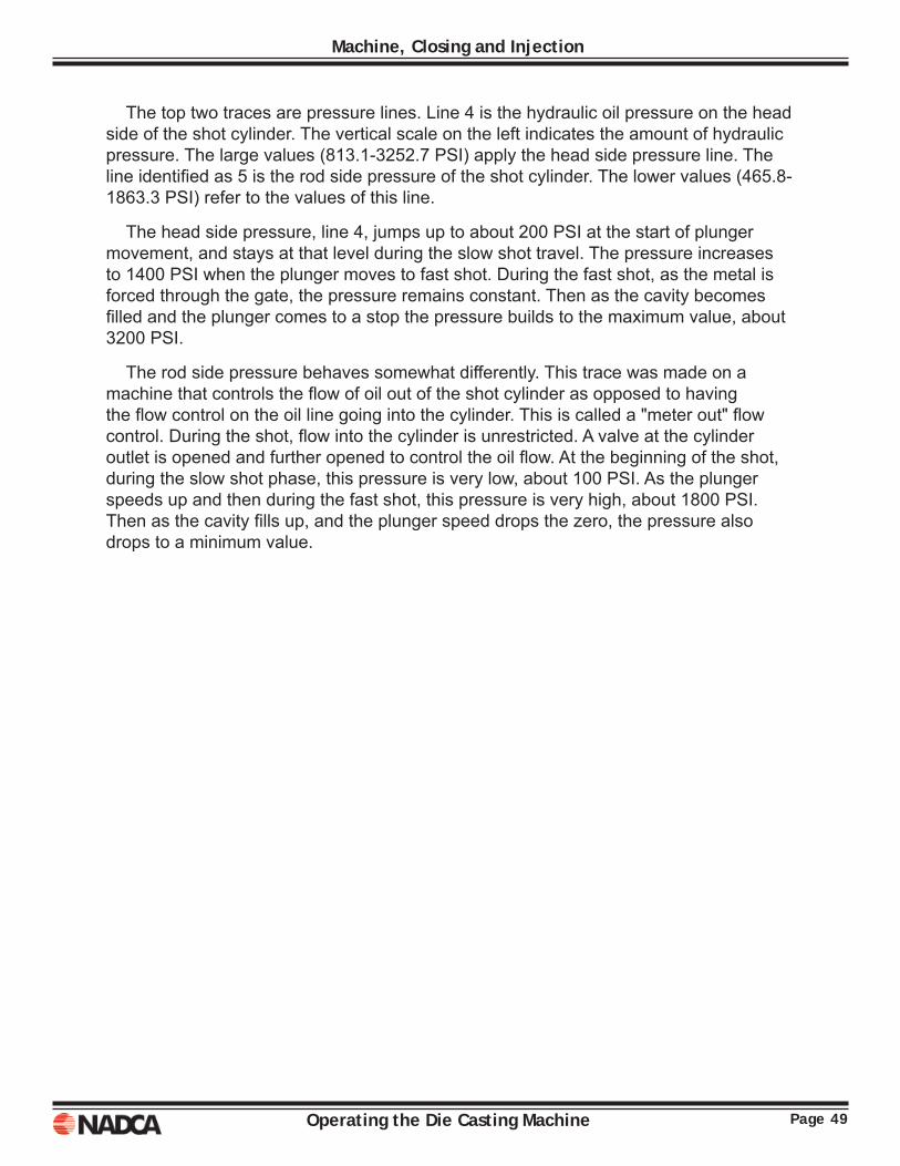
The top two traces are pressure lines. Line 4 is the hydraulic oil pressure on the head side of the shot cylinder. The vertical scale on the left indicates the amount of hydraulic pressure. The large values (813.1-3252.7 PSI) apply the head side pressure line. The line identifi ed as 5 is the rod side pressure of the shot cylinder. The lower values (465.8-1863.3 PSI) refer to the values of this line.
The head side pressure, line 4, jumps up to about 200 PSI at the start of plunger movement, and stays at that level during the slow shot travel. The pressure increases to 1400 PSI when the plunger moves to fast shot. During the fast shot, as the metal is forced through the gate, the pressure remains constant. Then as the cavity becomes fi lled and the plunger comes to a stop the pressure builds to the maximum value, about 3200 PSI.
The rod side pressure behaves somewhat differently. This trace was made on a machine that controls the fl ow of oil out of the shot cylinder as opposed to having the fl ow control on the oil line going into the cylinder. This is called a "meter out" fl ow control. During the shot, fl ow into the cylinder is unrestricted. A valve at the cylinder outlet is opened and further opened to control the oil fl ow. At the beginning of the shot, during the slow shot phase, this pressure is very low, about 100 PSI. As the plunger speeds up and then during the fast shot, this pressure is very high, about 1800 PSI. Then as the cavity fi lls up, and the plunger speed drops the zero, the pressure also drops to a minimum value.

Page 50 Operating the Die Casting Machine
Machine, Closing and Injection
Operating the Die Casting Machine Page 51
Chapter 5CONTROLS
Modern die casting machines (DCM) may differ widely in placement of the machine controls. In general, the basic machine functions are common with most differences occurring in machine accessories and ancillary equipment. This chapter will deal with the basic machine functions and safety related items and some specifi c cases of accessories and ancillary equipment. Accessories are defi ned as equipment that is optional and in addition to the basic machine functions. Examples of accessories are automated tie bar pulling systems or automated die locking systems. Examples of ancillary equipment are extractors, autoladles, robots, reciprocators and conveyors.
The machine controls can be segregated into several logical groups. First, there is a sequencer or logic system, the brains of the machine. The logic system may step the machine through a pre-programmed sequence, or may respond to inputs from the operation via a control panel or may respond to inputs from other devices, such as limit switches, pressure switches, or various transducers. This logic controller may be in the form of a programmable logic controller (PLC), a drum switch or a relay tree. This will depend on the machine's age and rebuild status. It is not uncommon to replace the machine controls with a modern PLC when rebuilding or remanufacturing a machine.
Another component of the machine controls system is input devices. These are components that send signals to the machine to report the status of various actuators. Examples are the limit switch activated by the crosshead, or the pressure switch that signals when the accumulator is fully recharged. Pushbuttons and selector switches are also devices that are used to interface with the machine controller. These are all considered to be "input" devices.
The last components of the machine control system are the "output" devices. The output devices control the motions of actuators or cylinders. An example of an output device is a solenoid. Solenoids shift valves directing hydraulic fl uid fl ow.
Discussion of the machine controls will begin with an example of a simple zinc DCM, followed by an example of a modern aluminum DCM work cell.
Page 52 Operating the Die Casting Machine
Controls
ZINC DCMControl functions accessed by the DCM operator are found in two locations, the operator control panel at the operator's work station, usually near the stationary platen, and the main electrical panel located near the motor and pumps.
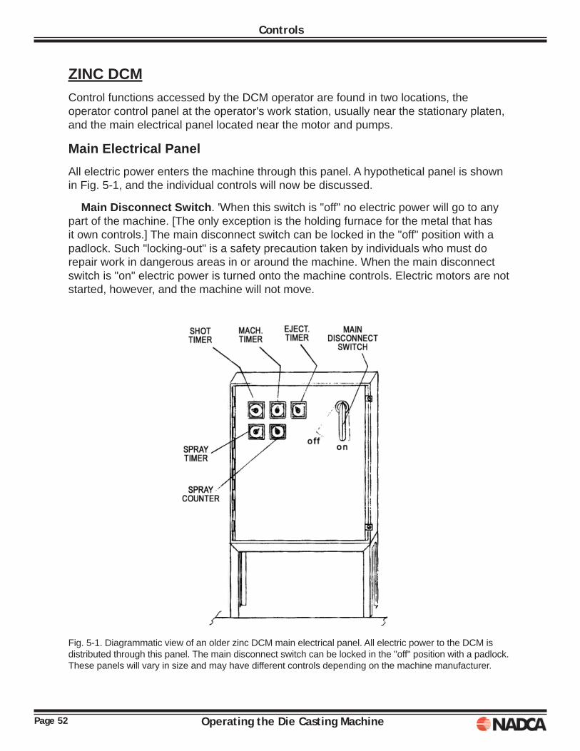
Main Electrical PanelAll electric power enters the machine through this panel. A hypothetical panel is shown in Fig. 5-1, and the individual controls will now be discussed.
Main Disconnect Switch. 'When this switch is "off" no electric power will go to any part of the machine. [The only exception is the holding furnace for the metal that has it own controls.] The main disconnect switch can be locked in the "off" position with a padlock. Such "locking-out" is a safety precaution taken by individuals who must do repair work in dangerous areas in or around the machine. When the main disconnect switch is "on" electric power is turned onto the machine controls. Electric motors are not started, however, and the machine will not move.
Fig. 5-1. Diagrammatic view of an older zinc DCM main electrical panel. All electric power to the DCM is distributed through this panel. The main disconnect switch can be locked in the "off" position with a padlock. These panels will vary in size and may have different controls depending on the machine manufacturer.
Page 53Operating the Die Casting Machine
Controls
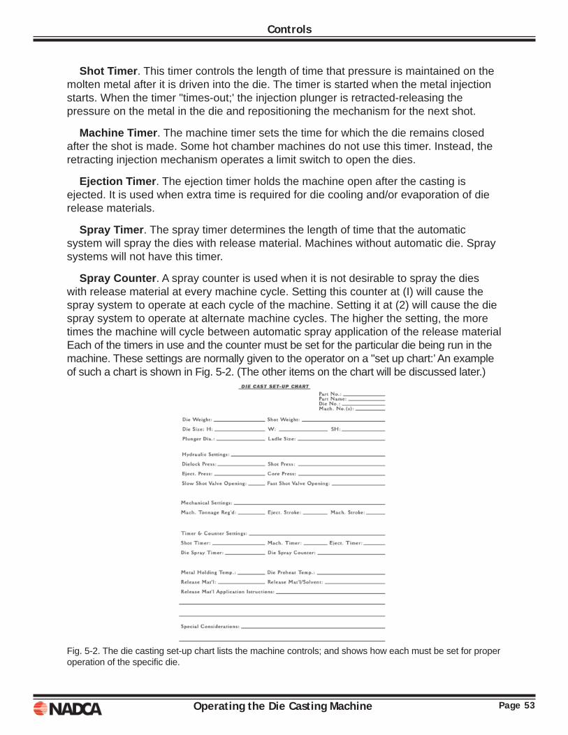
Shot Timer. This timer controls the length of time that pressure is maintained on the molten metal after it is driven into the die. The timer is started when the metal injection starts. When the timer "times-out;' the injection plunger is retracted-releasing the pressure on the metal in the die and repositioning the mechanism for the next shot.
Machine Timer. The machine timer sets the time for which the die remains closed after the shot is made. Some hot chamber machines do not use this timer. Instead, the retracting injection mechanism operates a limit switch to open the dies.
Ejection Timer. The ejection timer holds the machine open after the casting is ejected. It is used when extra time is required for die cooling and/or evaporation of die release materials.
Spray Timer. The spray timer determines the length of time that the automatic system will spray the dies with release material. Machines without automatic die. Spray systems will not have this timer.
Spray Counter. A spray counter is used when it is not desirable to spray the dies with release material at every machine cycle. Setting this counter at (I) will cause the spray system to operate at each cycle of the machine. Setting it at (2) will cause the die spray system to operate at alternate machine cycles. The higher the setting, the more times the machine will cycle between automatic spray application of the release material Each of the timers in use and the counter must be set for the particular die being run in the machine. These settings are normally given to the operator on a "set up chart:’ An example of such a chart is shown in Fig. 5-2. (The other items on the chart will be discussed later.)
Fig. 5-2. The die casting set-up chart lists the machine controls; and shows how each must be set for proper operation of the specifi c die.
Page 54 Operating the Die Casting Machine
Controls
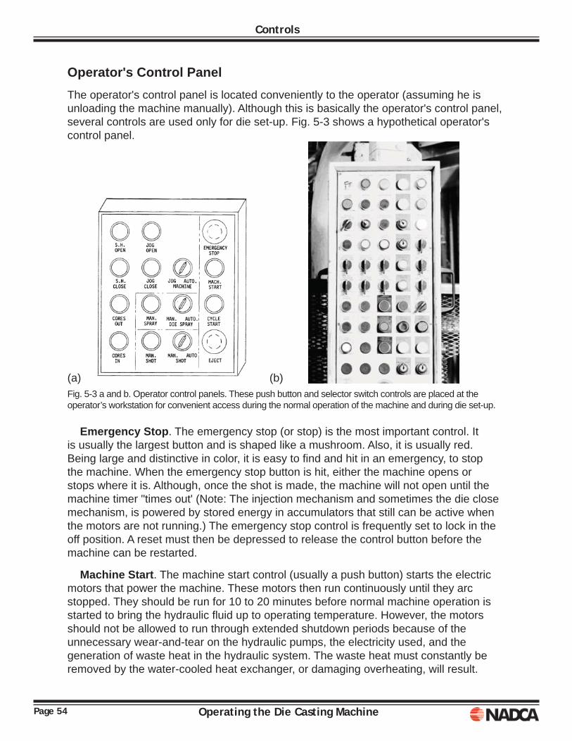
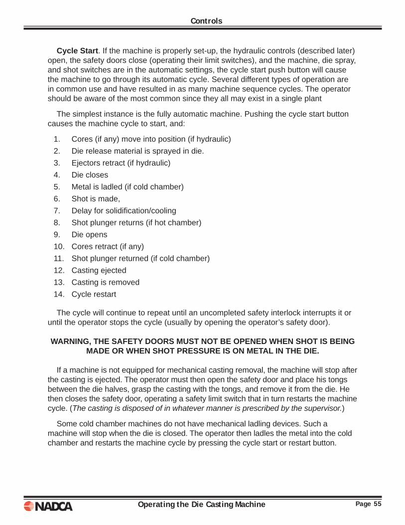
Operator's Control PanelThe operator's control panel is located conveniently to the operator (assuming he is unloading the machine manually). Although this is basically the operator's control panel, several controls are used only for die set-up. Fig. 5-3 shows a hypothetical operator's control panel.
(a) (b)Fig. 5-3 a and b. Operator control panels. These push button and selector switch controls are placed at the operator’s workstation for convenient access during the normal operation of the machine and during die set-up.
Emergency Stop. The emergency stop (or stop) is the most important control. It is usually the largest button and is shaped like a mushroom. Also, it is usually red. Being large and distinctive in color, it is easy to fi nd and hit in an emergency, to stop the machine. When the emergency stop button is hit, either the machine opens or stops where it is. Although, once the shot is made, the machine will not open until the machine timer "times out' (Note: The injection mechanism and sometimes the die close mechanism, is powered by stored energy in accumulators that still can be active when the motors are not running.) The emergency stop control is frequently set to lock in the off position. A reset must then be depressed to release the control button before the machine can be restarted.
Machine Start. The machine start control (usually a push button) starts the electric motors that power the machine. These motors then run continuously until they arc stopped. They should be run for 10 to 20 minutes before normal machine operation is started to bring the hydraulic fl uid up to operating temperature. However, the motors should not be allowed to run through extended shutdown periods because of the unnecessary wear-and-tear on the hydraulic pumps, the electricity used, and the generation of waste heat in the hydraulic system. The waste heat must constantly be removed by the water-cooled heat exchanger, or damaging overheating, will result.
Page 55Operating the Die Casting Machine
Controls
Cycle Start. If the machine is properly set-up, the hydraulic controls (described later) open, the safety doors close (operating their limit switches), and the machine, die spray, and shot switches are in the automatic settings, the cycle start push button will cause the machine to go through its automatic cycle. Several different types of operation are in common use and have resulted in as many machine sequence cycles. The operator should be aware of the most common since they all may exist in a single plant
The simplest instance is the fully automatic machine. Pushing the cycle start button causes the machine cycle to start, and:
1. Cores (if any) move into position (if hydraulic)2. Die release material is sprayed in die.3. Ejectors retract (if hydraulic)4. Die closes5. Metal is ladled (if cold chamber)6. Shot is made,7. Delay for solidifi cation/cooling8. Shot plunger returns (if hot chamber)9. Die opens10. Cores retract (if any)11. Shot plunger returned (if cold chamber)12. Casting ejected13. Casting is removed 14. Cycle restart
The cycle will continue to repeat until an uncompleted safety interlock interrupts it or until the operator stops the cycle (usually by opening the operator’s safety door).
WARNING, THE SAFETY DOORS MUST NOT BE OPENED WHEN SHOT IS BEING MADE OR WHEN SHOT PRESSURE IS ON METAL IN THE DIE.
If a machine is not equipped for mechanical casting removal, the machine will stop after the casting is ejected. The operator must then open the safety door and place his tongs between the die halves, grasp the casting with the tongs, and remove it from the die. He then closes the safety door, operating a safety limit switch that in turn restarts the machine cycle. (The casting is disposed of in whatever manner is prescribed by the supervisor.)
Some cold chamber machines do not have mechanical ladling devices. Such a machine will stop when the die is closed. The operator then ladles the metal into the cold chamber and restarts the machine cycle by pressing the cycle start or restart button.
Page 56 Operating the Die Casting Machine
Controls
Eject. The eject control is only used on machines having hydraulic ejection. If the machine is set up for automatic casting extraction, the eject button is operative only when the machine selector switch is in the jog position. If the machine is set up so that the operator must extract the casting, the eject control is operative when the dies are open. When depressed, this mushroom-headed button actuates a hydraulic cylinder connected to the ejector mechanism. The ejector pins push the casting out of the ejector die.
Die Spray & Manual Spray. During set-up and trouble shooting; it is desirable to have manual control of the die spray system that applies the release agent. When the die spray selector switch is in the auto position, the system sprays release material on the dies automatically every time the die closes. When in the manual position, the spray system only operates while the manual spray button is pushed.
Shot & Manual Shot. When the shot selector is in the auto position, the machine will make the shot automatically as soon as the die has closed (except with a hand-ladled cold chamber machine). However, when the selector is in the manual position, the machine cycle will stop when the die is closed. This arrangement allows the automatic cycle to be test run with no danger of shooting molten metal into a die that may not be properly closed. It is also possible to leave the machine closed without having metal in the die, as is sometimes necessary.
Machine. The machine selector switch lets the operator choose the automatic cycle providing normal operation, or the jog mode for setup and adjustment. In the jog position, the shot (injection) mechanism will not operate. All other machine movements can be controlled by their respective push buttons as described below.
Jog Open & Jog Close. With the machine selector switch set to the job position, the machine platen will move to the closed or open positions when the appropriate button is pushed. The platen will move only while the button is held in, producing short movements (jogs) that are necessary when setting dies. (Some machines have a special jog hydraulic circuit that requires a valve to be opened manually. The operator or set-up man should check with the supervisor when operating an unfamiliar machine.)
S.H. Open & S.H. Close. Shut height controls only appear on a machine with power-driven shut height adjustment mechanisms, which move the rear platen to open or close the die space. This adjustment allows the use of dies of different thickness. (Note: The toggle mechanism must always be completely straight when the die is closed). During operation, the die will expand slightly as it approaches operating temperature. This expansion will either slow down the die closing movement or stop the machine completely. It is then necessary to open the shut height slightly. When doing this the operator must watch the "fl ash" on the casting. If excessive fl ash develops on the shot following the S.H. adjustment, too much adjustment was made. Machines not having power driven shut height controls must be adjusted manually by rotation of the tie bar nuts at the rear platen.
Page 57Operating the Die Casting Machine
Controls
Cores Out & Cores In. Core operating controls are provided on machines equipped for dies with hydraulic core pulls. The controls provide for moving such cores in or out for set-up, lubrication, or trouble shooting. The switches should function only when the machine selector switch is in the jog position.
Hydraulic ControlsA thorough study of hydraulic circuit functions is beyond the scope of this description of how to operate the die casting machine. However, certain of the hydraulic valves must be adjusted, opened, or closed by the operator or set-up man under certain conditions. These controls must be identifi ed and the end results of their adjustment must be understood.
Slow Shot Control Valve. Most machines have some provision for advancing the injection (shot) plunger slowly for the fi rst part of the stroke. This eliminates splashing" of the metal before the pouring or fi lling port is closed by the plunger. In hot chamber machines, this slow advance is sometimes continued until the metal fi lls the gooseneck and nozzle. Time is thus allowed for venting the air displaced from these components. Although some machines have no speed control on the slow shot, others have a valve in the hydraulic system that can be turned to adjust the speed.
Fast Shot Control Valve. The large shot hydraulic lines have several control valves. At least one of these has a hand-wheel that can be turned manually to close the line. The stored energy of the accumulator is thus prevented from accidentally activating the injection (shot) plunger. By partially closing this control valve, the shot speed can be reduced to any desired value.
Manual/Jog/Inch Control. Some machines have a special manual circuit so that during setup, the machine can be manually open and closed slowly. With such a circuit, the manual valve must be opened manually. The valve is usually located near the operator's control panel.
Deceleration Valves. On large, high speed machines where the natural toggle motion and the die close cylinder cushion will not overcome the machine's momentum, a deceleration valve is provided. Limit switches controlling these valves are operated by cams driven by the moving platen. The cams must be adjusted to suit the stroke being used.
Page 58 Operating the Die Casting Machine
Controls
Safety Limit SwitchesThere are several limit switches on the die casting machine. Most control the sequential steps in the machine cycle. Some perform functions directly associated with the personal safety of the operator. These safety limit switches must be checked out by the operator each time he starts the machine.
Die Lock L.S. The toggle mechanisms must be in the proper (straight) position before the shot is made. If the shot is made when the toggles are out of position, they will not hold against the force exerted on the metal. The die will open and the molten metal will spray out. A limit switch is therefore, fi tted so that it will be actuated by the toggle crosshead when the toggle is fully erected. It is important that the limit switch closes at the very end of the crosshead travel.
Safety Door L.S. Each safety door (enclosing the die spaces) closes a limit switch when the door is properly closed. If one of these switches is open, the machine will not close. Sometimes, large machines have power-operated safety doors. These doors have a safety bar to detect any object (arm, hand, body, etc.) that may get caught as they close. When such an object is detected, the door and the machine instantly return to the open position and the machine cycle stops.
Casting Removed L.S. A limit switch, electric eye, infrared detector, proximity or vision device is used to detect the casting as it is being automatically removed from the die. Naturally, machines on which the operator removes the casting will not have such a device. If the removal of the casting is not detected, the machine cycle will stop. Usually, the detector must be adjusted differently for each die run in a particular machine.
A CASTING REMAINING BETWEEN THE DIE HALVES MAY PRESENT A SAFETY HAZARD TO THE OPERATOR.
Individual machines may have other limit switches that are adjustable. If so, the supervisor should be sure the operators are aware of their functions.
Stroke AdjustmentThe machine stroke is set by turning the stroke adjustment screw at the back of the machine-dose cylinder. The location of the stroke adjustment is shown in Fig 3-22. Set screws or a jam nut are usually provided to lock the screw when the desired adjustment is achieved.
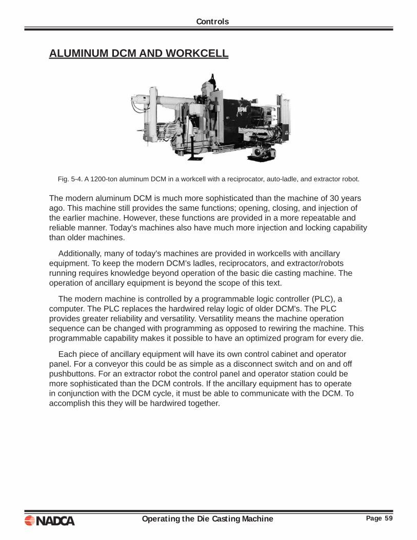
Page 59Operating the Die Casting Machine
Controls
ALUMINUM DCM AND WORKCELL
Fig. 5-4. A 1200-ton aluminum DCM in a workcell with a reciprocator, auto-ladle, and extractor robot.
The modern aluminum DCM is much more sophisticated than the machine of 30 years ago. This machine still provides the same functions; opening, closing, and injection of the earlier machine. However, these functions are provided in a more repeatable and reliable manner. Today's machines also have much more injection and locking capability than older machines.
Additionally, many of today's machines are provided in workcells with ancillary equipment. To keep the modern DCM’s ladles, reciprocators, and extractor/robots running requires knowledge beyond operation of the basic die casting machine. The operation of ancillary equipment is beyond the scope of this text.
The modern machine is controlled by a programmable logic controller (PLC), a computer. The PLC replaces the hardwired relay logic of older DCM's. The PLC provides greater reliability and versatility. Versatility means the machine operation sequence can be changed with programming as opposed to rewiring the machine. This programmable capability makes it possible to have an optimized program for every die.
Each piece of ancillary equipment will have its own control cabinet and operator panel. For a conveyor this could be as simple as a disconnect switch and on and off pushbuttons. For an extractor robot the control panel and operator station could be more sophisticated than the DCM controls. If the ancillary equipment has to operate in conjunction with the DCM cycle, it must be able to communicate with the DCM. To accomplish this they will be hardwired together.
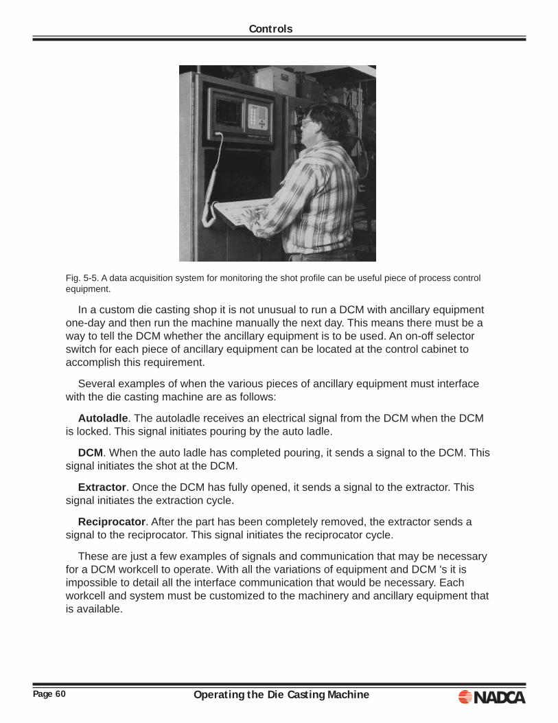
Page 60 Operating the Die Casting Machine
Controls
Fig. 5-5. A data acquisition system for monitoring the shot profi le can be useful piece of process control equipment.
In a custom die casting shop it is not unusual to run a DCM with ancillary equipment one-day and then run the machine manually the next day. This means there must be a way to tell the DCM whether the ancillary equipment is to be used. An on-off selector switch for each piece of ancillary equipment can be located at the control cabinet to accomplish this requirement.
Several examples of when the various pieces of ancillary equipment must interface with the die casting machine are as follows:
Autoladle. The autoladle receives an electrical signal from the DCM when the DCM is locked. This signal initiates pouring by the auto ladle.
DCM. When the auto ladle has completed pouring, it sends a signal to the DCM. This signal initiates the shot at the DCM.
Extractor. Once the DCM has fully opened, it sends a signal to the extractor. This signal initiates the extraction cycle.
Reciprocator. After the part has been completely removed, the extractor sends a signal to the reciprocator. This signal initiates the reciprocator cycle.
These are just a few examples of signals and communication that may be necessary for a DCM workcell to operate. With all the variations of equipment and DCM 's it is impossible to detail all the interface communication that would be necessary. Each workcell and system must be customized to the machinery and ancillary equipment that is available.
Page 61Operating the Die Casting Machine
Controls
A sophisticated DCM may also be equipped with shot/process monitoring and data acquisition equipment. This equipment can be set-up to monitor the process variables discussed in Chapter 4. In addition to monitoring, many die casters are using this equipment to determine and establish the values of the process variables prior to monitoring them. Also, the maintenance department can use this equipment to diagnose machine problems.
REVIEW
Controls have been discussed by looking at two examples, a simple zinc OCM and an aluminum workcell. In is clear that the basic functions of all DCM's are the same. The machine opens and closes and metal is injected. The controls determine the machine sequence and how the actuators (cylinders) are energized to perform the machine functions. If the machine has accessories, such as a tie bar pulling mechanism or multiple stage injection, the controls become more numerous and sophisticated. Another control issue is ancillary equipment. Ancillary equipment must be interfaced with the OCM for safe and productive operation. Finally, control technology has changed in the last half of the twentieth century. Machines in the 1950's had a control cabinet full of relays; today the control cabinet contains a PLC.

Page 62 Operating the Die Casting Machine
Controls
Operating the Die Casting Machine Page 63
Chapter 6SETUP PROCEDURE
Actual setting of dies may or may not be part of the normal duties of the machine operator.
However, the operator should know how to set dies because:
1. he must be able to check the set-up, 2. he may be required to set dies on a day-rate basis, and 3. die setting is usually the next advancement set for a skilled operator
Die setup and teardown has gone through a revolution in thinking in the several past decades. In short, setup time is not productive and must be minimized. Dr. Shigeo Shingo an International consultant, had a great impact on manufacturing with his teachings in three concepts: Just in time (J IT), Single Minute Exchange of Dies (SMED), Zero Quality Control. Dr. Shigeo introduced the SMED concept.
SMED is an acronym for Single Minute Exchange of Dies. This means that the entire die change process, from last good part to fi rst good part is completed in less than 10 minutes. This is the goal. Some die casters with both large and small dies have already achieved this goal.
Dr. Shigeo’s approach to developing the SMED concept was to isolate and identify the setup time as two entities: internal setup time and external setup time. According to him, a simple approach to achieving a quick setup and changeover of dies can be done in the following steps:
o Separating internal and external as it is existing o Converting internal to external setup o Streamlining all aspects of the setup operation
Page 64 Operating the Die Casting Machine
Setup Procedure
EXAMPLEThis chapter uses the setup of a single cavity hot chamber die as an example. Each step of the setup is listed and explained. Thirty-three steps are required to set the die, teardown is not included in the example. At the conclusion of the example, the fi rst step of SMED is exercised:
Separating internal and external as it is existingAssuming there is no die in the machine, the following steps are to be followed:
1. Deactivate Shot. The shot mechanism is deactivated by closing both the slow shot control valve and the fast shot control valve. These valves must be closed because the stored energy in the accumulators provide enough power to actuate the shot system even when the main disconnect switch is locked out. Hot chamber machines must also have the shot plunger taken out of the gooseneck or physically blocked. (If there is no die in the machine, the plunger should already have been removed or blocked.)
2. Open Machine. The machine is opened by turning the Machine Selector Switch on the operator's control panel to Manual (jog/inch) and then pushing the open button until the machine platen is open. On some machines, a die close speed control valve will have to be closed and a manual valve opened. The main disconnect switch must then be locked out. Note: Before locking out the main disconnect switch, it may be convenient to make the measurements detailed in Step 8 and Fig. 6-5 to select bumper pins of the correct length.
3. Clean Die Mounting Surfaces. With the main disconnect switch locked out, clean, (scrape, if necessary) all dirt, grease, and die cast metal from the machine platens. Be sure T-slots are clean so clamp bolts can be placed wherever necessary. Any burrs from previous misuse must be fi led fl ush. Select cold chamber per set-up chart and install through front platen.
4. Clean Mounting Surfaces of Die. Like the machine, the die surfaces must be free of grease, dirt, and die cast metals.
5. Insert Eyebolts into Die. Eyebolts should be of the shoulder type, and should be threaded into the die until the shoulder seats against the die as shown in Fig. 6-1.
6. Install W.L. Pipes. If the water line pipes are not in the die, it is usually most convenient to install them before the die is placed in the machine. Sometimes, water lines are placed in areas where pipes cannot be installed after the die is in the machine. Each water line inlet or outlet should be identifi ed by letters and numbers stamped into the die beside the hole as show in Fig. 6-2. The letters W.L. identify the hole as a water line. The words IN and OUT show if the water is to enter (in) or leave (out) the die through that particular hole. The use of the number identifi cation is described later. Special consideration must be given to two-way fi ttings to insure that the inner tube is not too long (stopping or reducing water fl ow) or too short (water fl ow failing to reach required cooling area).
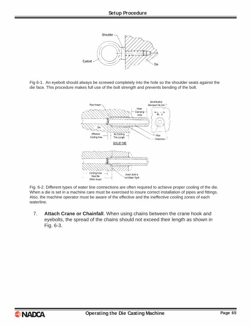
Page 65Operating the Die Casting Machine
Setup Procedure
Fig 6-1. An eyebolt should always be screwed completely into the hole so the shoulder seats against the die face. This procedure makes full use of the bolt strength and prevents bending of the bolt.
Fig. 6-2. Different types of water line connections are often required to achieve proper cooling of the die. When a die is set in a machine care must be exercised to insure correct installation of pipes and fi ttings. Also, the machine operator must be aware of the effective and the ineffective cooling zones of each waterline.
7. Attach Crane or Chainfall. When using chains between the crane hook and eyebolts, the spread of the chains should not exceed their length as shown in Fig. 6-3.
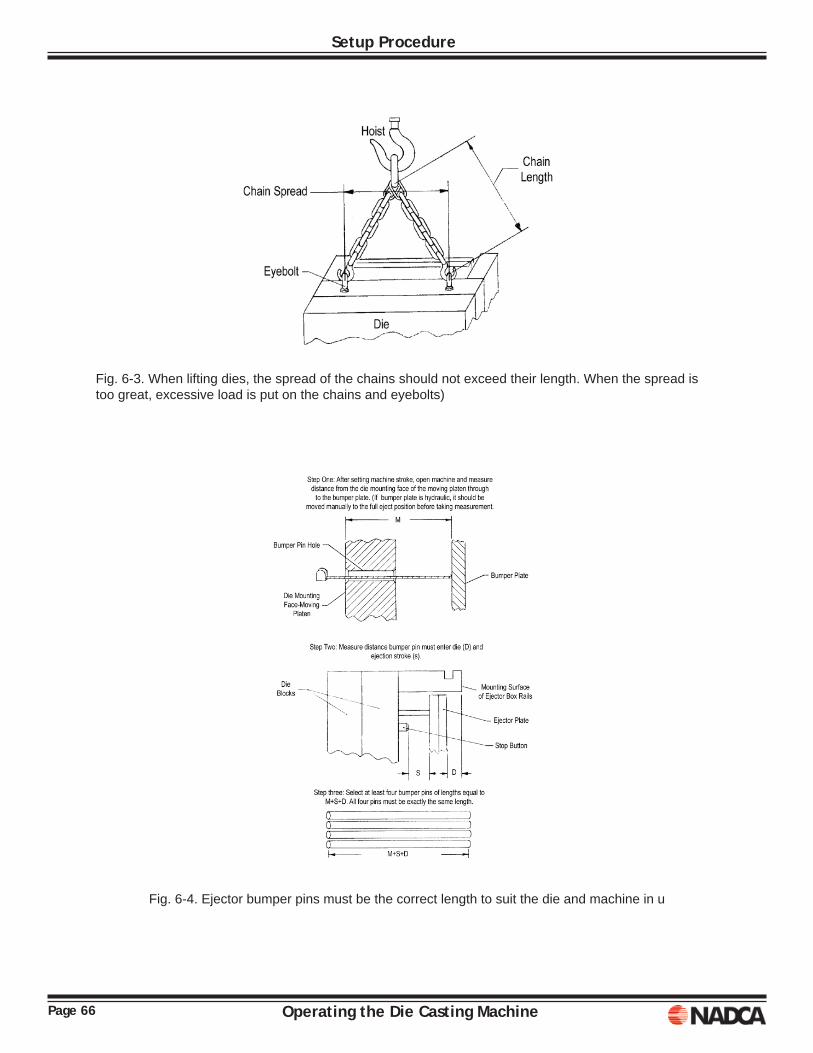
Page 66 Operating the Die Casting Machine
Setup Procedure
Fig. 6-3. When lifting dies, the spread of the chains should not exceed their length. When the spread is too great, excessive load is put on the chains and eyebolts)
Fig. 6-4. Ejector bumper pins must be the correct length to suit the die and machine in u
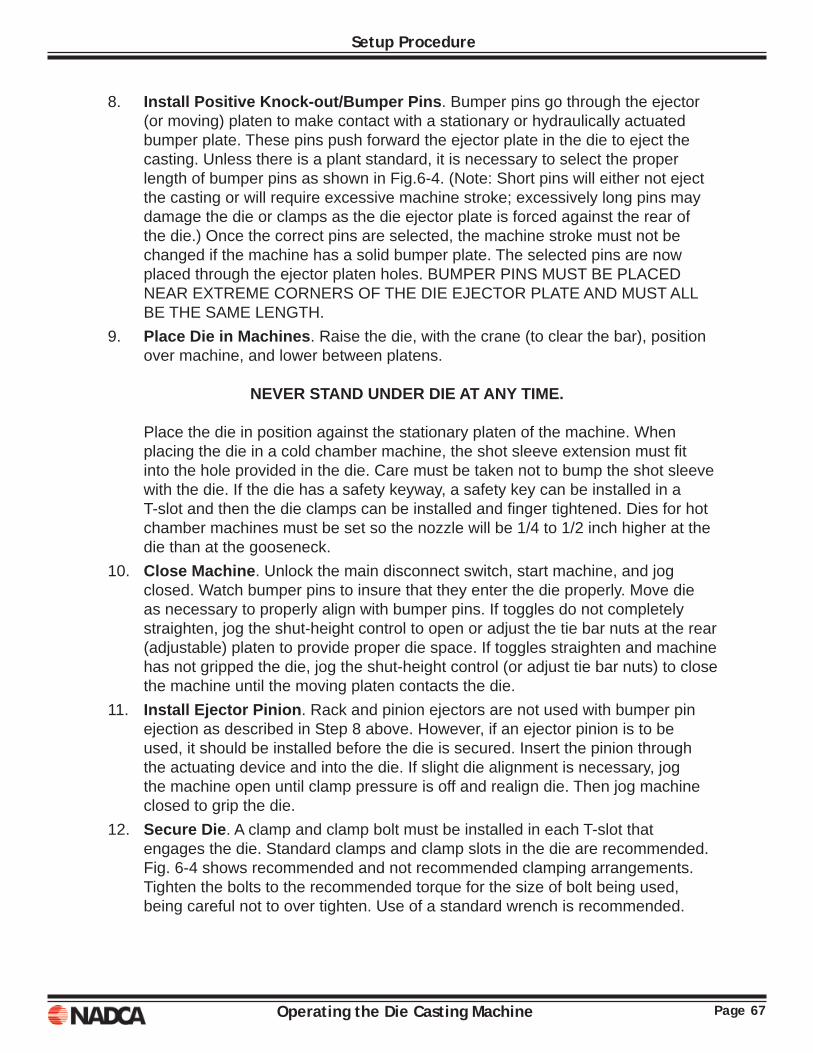
Page 67Operating the Die Casting Machine
Setup Procedure
8. Install Positive Knock-out/Bumper Pins. Bumper pins go through the ejector (or moving) platen to make contact with a stationary or hydraulically actuated bumper plate. These pins push forward the ejector plate in the die to eject the casting. Unless there is a plant standard, it is necessary to select the proper length of bumper pins as shown in Fig.6-4. (Note: Short pins will either not eject the casting or will require excessive machine stroke; excessively long pins may damage the die or clamps as the die ejector plate is forced against the rear of the die.) Once the correct pins are selected, the machine stroke must not be changed if the machine has a solid bumper plate. The selected pins are now placed through the ejector platen holes. BUMPER PINS MUST BE PLACED NEAR EXTREME CORNERS OF THE DIE EJECTOR PLATE AND MUST ALL BE THE SAME LENGTH.
9. Place Die in Machines. Raise the die, with the crane (to clear the bar), position over machine, and lower between platens.
NEVER STAND UNDER DIE AT ANY TIME.
Place the die in position against the stationary platen of the machine. When placing the die in a cold chamber machine, the shot sleeve extension must fi t into the hole provided in the die. Care must be taken not to bump the shot sleeve with the die. If the die has a safety keyway, a safety key can be installed in a T-slot and then the die clamps can be installed and fi nger tightened. Dies for hot chamber machines must be set so the nozzle will be 1/4 to 1/2 inch higher at the die than at the gooseneck.
10. Close Machine. Unlock the main disconnect switch, start machine, and jog closed. Watch bumper pins to insure that they enter the die properly. Move die as necessary to properly align with bumper pins. If toggles do not completely straighten, jog the shut-height control to open or adjust the tie bar nuts at the rear (adjustable) platen to provide proper die space. If toggles straighten and machine has not gripped the die, jog the shut-height control (or adjust tie bar nuts) to close the machine until the moving platen contacts the die.
11. Install Ejector Pinion. Rack and pinion ejectors are not used with bumper pin ejection as described in Step 8 above. However, if an ejector pinion is to be used, it should be installed before the die is secured. Insert the pinion through the actuating device and into the die. If slight die alignment is necessary, jog the machine open until clamp pressure is off and realign die. Then jog machine closed to grip the die.
12. Secure Die. A clamp and clamp bolt must be installed in each T-slot that engages the die. Standard clamps and clamp slots in the die are recommended. Fig. 6-4 shows recommended and not recommended clamping arrangements. Tighten the bolts to the recommended torque for the size of bolt being used, being careful not to over tighten. Use of a standard wrench is recommended.
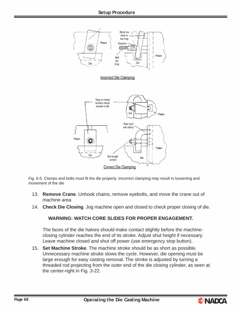
Page 68 Operating the Die Casting Machine
Setup Procedure
Fig. 6-5. Clamps and bolts must fi t the die properly. Incorrect clamping may result in loosening and movement of the die
13. Remove Crane. Unhook chains, remove eyebolts, and move the crane out of machine area
14. Check Die Closing. Jog machine open and closed to check proper closing of die.
WARNING: WATCH CORE SLIDES FOR PROPER ENGAGEMENT. The faces of the die halves should make contact slightly before the machine-
closing cylinder reaches the end of its stroke. Adjust shut height if necessary. Leave machine closed and shut off power (use emergency stop button).
15. Set Machine Stroke. The machine stroke should be as short as possible. Unnecessary machine stroke slows the cycle. However, die opening must be large enough for easy casting removal. The stroke is adjusted by turning a threaded rod projecting from the outer end of the die closing cylinder, as seen at the center-right in Fig. 3-22.

Page 69Operating the Die Casting Machine
Setup Procedure
16. Set Ejector. If mechanical die ejectors are used, the hydraulic or mechanical ejector mechanism must be connected. Side hydraulic units require adjustment, installation of the drive gear, and replacement of the gear cover. Mechanical systems require the hookup of some type of linkage. The varieties of these mechanisms exceed the scope of this book. If installation is not obvious, the set-up man should get detailed instructions from his supervisor. Once the ejector is connected, the machine should he restarted and the operation of the ejector checked. Adjustments should be made until correct operation is achieved. The die is left in open position and the machine is again shut off.
17. Install Nozzle. Hot-chamber machines have a nozzle between the gooseneck and the die. The nozzle is held in place and the gooseneck adjusted until the nozzle is held loosely. The gooseneck is adjusted by turning a pinion in the gooseneck supporting frame (also called the A-frame). While slowly rotating the nozzle to insure proper seating, the A-frame is tightened against it. The A-frame clamping nuts are then HAND TIGHTENED.
18. Heat Nozzle. Set nozzle torches to apply a lazy, low fl ame over the nozzle and allow heating for about 20 minutes. The torch arrangement (shown in Fig. 6-6) must heat the nozzle uniformly. Hot spots must be avoided.
Fig. 6-6. Nozzle heating torches must be set to give all even ge1ltle fl ame that wraps around the nozzle. Spots of hot fl ame can damage the nozzle and should be avoided.
Page 70 Operating the Die Casting Machine
Setup Procedure
19. Connect Water Lines. One or more water manifolds on or near the machines supply die cooling water. Each manifold has a series of outlets, and each outlet has a control valve. A hose must be connected from a manifold valve to each die water line inlet. Valve number 1 must be connected to die water line number 1. Valve 2 connects to water line 2 and so on. This valve number to water line number sequence must be strictly adhered to so that lines leading to overheated and overcooled die areas can be readily identifi ed for adjustment of the water fl ow rates to achieve optimum casting conditions. A hose must also be connected between each die water line outlet and the drain.
The same numbering sequence must be followed on the drain. As each water line is connected, it is turned on, check for leaks, and the fl ow into the drain is checked. If water is not fl owing into the drain, the line is plugged and must be opened. After each line has been checked, the water fl ow is turned off.
20. Set Safety Ratchet. A safety ratchet mechanism prevents the moving platen from closing when the safety door is open. Check the operation of this safety device and adjust as necessary.
21. Set Deceleration Valve. The cams actuating the deceleration valve limit switch are held in place with set screws. The appropriate set screw is loosened and the earn adjusted so that the roller on the decelerating valve limit switch is completely on the appropriate cam with the platen in the die open and the die closed positions. The set screws must then be tightened.
22. Lubricate Die. Start the machine. Ejector pins, guide pins, and core slides must be lubricated. Ejector pins will be extended out of die if mechanically operated. If hydraulic, they must he moved out for lubrication by the eject push-button. Jog the die closed and lubricate the mechanism inside the ejector box. Lubricate exposed parts of core slides. Pump grease into all grease fi ttings on the die.
23. Install Die Heating. Gas torches or other types of heaters are placed around the die for preheating. The die halves should he in contact to help both heat uniformly unless a heater designed to fi t between the die faces is in use. Both die halves should have the same number of heating units. Equal heating is important because the die expands as it is heated. If both halves are not expanded equally, they will not close properly, and incomplete closure may cause a serious safety hazard if metal is injected.
Expansion will also cause the die to tighten in the machine, stretching the tie bars and, perhaps, bending the platens. To guard against excessive tightening, the machine should be jogged open to move the toggle crosshead about 1/2 inches. This slight movement will not open the die, but will loosen the toggle suffi ciently to prevent locking as the die expansion generates force. The die should be allowed to heat to operating temperature before making the fi rst casting.
Page 71Operating the Die Casting Machine
Setup Procedure
24. Install Release Spray. Die release material is usually contained in a tank that is pressurized with compressed air. This tank must be fi lled and the pressure adjusted. Machines not equipped with automatic spray systems to apply the release material have a hand spray gun or wand. The spray gun must be connected to the pressure tank and checked for proper operation. If there is an automatic system, the spray heads must be attached to the machine and adjusted to apply the release material evenly over the die surfaces. The machine should be opened as necessary, but should be closed again as described in Step 23.
25. Close Safety Doors. Check safety doors, and the limit switches they operate, to insure proper operation. The operator's door must move freely and easily. After checking, turn off the machine and lock the main disconnect switch.
26. Tighten Nozzle. The nozzle should have expanded suffi ciently from heating to tighten the A-frame clamp nuts. If not, they must be tightened with a wrench. If excessive expansion has occurred, the springs between the clamp nuts and the A-frame will be fully compressed. If the springs are compressed, check the nozzle temperature. If it is turning color from the heat, turn down the torches. If cooling does not free the springs, the clamp nuts must be loosened. Excessive pressure can bend the nozzle, destroy the seal at the die and/or gooseneck, bend the die, or stretch the die clamps.
27. Replace Shot Plunger. Install new rings on the plunger (if hot chamber) and fi t plunger into gooseneck. The plunger rings should be turned so that the split gaps are not in line with each other. Plunger must fi rst be placed on edge of furnace until it is preheated suffi ciently to dry off ALL moisture. Any moisture carried on an object placed in molten metal will instantly turn to steam with explosive results. Such reactions splash molten metal over a wide area. Once the plunger is installed, the safety shields are replaced on the furnace an A frame. The plunger is inserted manually into the gooseneck. The shot cylinder must never be used to start the plunger into the gooseneck.
28. Set All Timers and Metal Temperatures. The holding furnace must be fi lled, and the metal temperature control set at the desired temperature, The recommended time settings and metal temperature should be specifi ed on the set-up chart as shown in Fig. 5-2.
29. Check Hydraulic System. Check accumulator levels and hydraulic pressures. Adjust pressures and have accumulators charged as necessary.
30. Check Machine Lube System. Check the machine lubricator to be sure it is full. Check the lines for any fl attened or kinked areas. Check that all machine wear points (tie bar bushings, toggle pins, etc...) are being adequately supplied with lubricant.
31. Turn Off Die Heating Torches. When die is suffi ciently preheated, the die heating torches can be turned down to low fl ame or sometimes turned off completely. Removal of torches from the machine is not recommended as they are required during temporary shut downs.
Page 72 Operating the Die Casting Machine
Setup Procedure
32. Check Lock- Up Sequence. Start machine and jog open and close. Check the proper tie bar strain (rear platen should move about 1/32 in.) and core slide operation. Make any fi nal shut -height or stroke adjustments. Leave machine OPEN.
33. Make Shot. Open slow shot control valve, open fast shot control about halfway, open die close valve and close jog valve, if used. Open water valve to heat exchanger.
CLEAR PERSONNEL FROM AREAS IN SIGHT OF INJECTION END OF MACHINE.
Place "Shot" selector switch to “Man” Place “machine” selector switch to ”Auto”, Place “Die Spray” selector switch to “Man” and spray release material on dies.
Close operator safety door. When machine has properly closed, and all personnel are clear, make the shot by pushing the "Man. Shot" button. Check nozzle for metal leaks at gooseneck and die. Turn on cooling water to plunger tip if cold-chamber, and to sprue bushing and spreader if hot -chamber. Make several shots, checking for proper die closing, excessive fl ash and ejection problems. If cold chamber, check for excessive plunger fl ash. The die and machine are now ready for normal operation. The individuals responsible for set-up should study the operating and maintenance procedure manuals supplied by the machine manufacturers. Each make and size of machine may have unique equipment that requires special consideration.
Page 73Operating the Die Casting Machine
Setup Procedure
The following is a condensed list of the 33 setup steps. How can this setup sequence be improved using SMED techniques.
1. Deactivate shot 2. Open DCM 3. Clean die mounting surface 4. Clean mounting surfaces of die 5. Insert eyebolts into die 6. Install cooling line pipes 7. Attach crane or chain fall 8. Install bumper pins 9. Place die in DCM 10. Close DCM 11. Install ejector pinion 12. Secure die 13. Remove crane 14. Check die closing 15. Set DCM stock 16. Set ejector 17. Install nozzle 18. Heat nozzle 19. Connect cooling lines 20. Set safety ratchet 21. Set deceleration 22. Lubricate die 23. Install die heating 24. Install release spray 25. Close safety doors 26. Tighten nozzle 27. Replace shot plunger 28. Set all timers and metal temperatures 29. Check Hydraulic lines 30. Check machine lube system 31. Turn off die heating torches 32. Check lock-up sequence 33. Make shot
Page 74 Operating the Die Casting Machine
Setup Procedure
Step one of SMED is to sort these activities into external and internal activities. The following items have been sorted as external activities:
5. Insert eyebolts into die. Eyebolts will be installed into each die half permanently, they could be tack welded to make sure they do not get lost and also prevent rotation.
6. Install cooling pipe in die. All cooling pipes are installed into the die as it comes from die Repair, the only time cooling pipes are removed is for repair and maintenance.
18. Heat nozzle. Nozzle can be pre-heated just as the die is pre-heated off-line. 20. Set safety ratchet. Operation of the safety ratchet can be observed as an
external activity. Adjustment is not necessary. 22. Lubricate die. Die lubricated as part of die maintenance. 23. Install die heating. Die is pre-heated at the die pre-heat station and will be set hot.27. Replace shot plunger. Plunger does not have to be removed for the setup as
long as it is physically blocked and cannot move or drift. 29. Check hydraulic lines. Hydraulic lines are checked as part of a preventative
maintenance program. 30. Check machine lube system. The machine lube system is checked as part of a
preventative maintenance program. 31. Turnoff die heating torches. Die is pre-heated at the die pre-heat station and
will be set hot.
Operating the Die Casting Machine Page 75
Chapter 7START UP & SHUT DOWN PROCEDURES
START UP
SHIFT “WALK-AROUND” INSPECTIONS
When starting the machine at the beginning of the shift or after any shut-down period, certain things must be done in a particular sequence. Otherwise, there is a defi nite chance of personal injury or damage to the equipment. The items in this procedure are inspections designed to fi nd trouble before it develops into serious proportions. These inspections are to be made once each shift, plus each time the machine is started after a shut-down period.
1. Check machine for water and hydraulic fl uid leaks. Loose hoses must be tightened. If leaks are found, inform the supervisor.
2. Check all safety switches and all other controls for proper operation. 3. Check accumulator levels, hydraulic fl uid level in reservoir, and hydraulic
pressures. Check for excessive or unusual noise from hydraulic pumps. 4. Check that the water valve to the heat exchanger is open. Check that the
hydraulic fl uid temperature does not exceed 120°F or the fl uid manufacturer’s maximum temperature recommendation.
5. Check settings of all timers, counters, temperatures, water valves, selector switches, and hydraulic valves to be sure they conform to the set-up chart values.
6. Check machine lubrication system. 7. Check for excessive drift of the shot plunger when at bottom of stroke if hot-
chamber. Drift is a downward movement of the plunger after the shot, caused by metal leaking past the rings. If drift is excessive, consult supervisor on changing rings, plunger or gooseneck. If cold-chamber, check for excessive fl ash around the piston tip.
8. Check locking tonnage. All tie bar nuts should be tight before making any casting.
Page 76 Operating the Die Casting Machine
Start Up & Shut Down Procedures
START-UP PROCEDURE
When starting to operate the machine after any shut-down period, the operator should fi rst make the start-up inspections listed above. He/She should then:
1. Turn machine on, and if recommend by the DCM manufacturer, cycle the pumps on-off quickly six to eight times. This procedure extends hydraulic pump life by lubricating the rotor at low speeds, and is especially important if the machine has been shut down for a long period.
2. Skim dross from holding furnace. Rest the perforated skimmer at the edge of the furnace to let metal drip out of the dross back into the melt. Deposit dross in molds. Aluminum die casting metal may form sludge. Existence of sludge is checked by inserting a rod to within a few inches of the furnace bottom. If a sandy, semi-liquid, solid condition is felt, as the rod is moved back and forth, sludge has developed. Once sludge develops in aluminum, the condition cannot be corrected in the holding furnace; the metal must be removed and returned for refi ning. To minimize sludging, aluminum should be maintained at a temperature above 1130°F. To minimize the formation of aluminum oxide on the furnace walls, the aluminum should be maintained at a temperature less than 1220°F.
3. Check the temperature of the metal in the holding furnace and the pyrometer setting. Metal must be at the temperature specifi ed on the set-up chart before making castings.
4. Some cold-chamber machines have automatic ladles. The mechanism must be checked out to be sure that all controls are properly set and functioning. It is important that exactly the correct amount of metal is ladled into the cold chamber. The ladle mechanism and the pouring trough leading to the cold chamber must be properly aligned to prevent molten metal spills during pouring. Spillage of molten metal can cause fi res when the metal falls on fl ammable material such as grease or oil on the fl oor or the machine.
5. The die must be cleaned of any fl ash, excessive grease, dirt, rags, and other foreign materials. Lubricate all moving parts of the die (i.e., ejector pins, guide pins, core slides, cam surfaces and core locks). Care must be taken to lubricate all moving parts inside the ejector box. Some wear points inside the ejector box are not always easy to see. Get an inspection lamp, if necessary.
6. Jog the die close button and watch for any misalignment. Special care must be taken when the die includes core slides. If core slides are hydraulically actuated, they should be jogged in and out separately during the inspection.
7. Open the shot valves as noted on the set-up chart. It is desirable for safety reasons to open the shot valve partially so that the speed of the fi rst shot is reduced. Some dies must be completely fi lled with metal on the fi rst shot or parts of the casting will stick in the die. For such dies, the high speed shot valve should be completely opened. If the set-up chart does not tell how the shot valve is to be set, the operator should check with his supervisor.
Page 77Operating the Die Casting Machine
Start Up & Shut Down Procedures
8. Turn on the cooling water to the shot plunger tip (if cold chamber) or to the sprue spreader (if hot chamber).
9. CLEAR PERSONNEL FROM SHOT END OF MACHINE. Any machine that has been shut down presents a safety hazard when making the
fi rst shot of a series. If the die was changed, there may have been an improper set-up of the metal injection mechanism. Thermal expansions and contractions could have loosened joints resulting in leakage of the molten metal. Also, there is a chance that the die is not completely sealed and molten metal will shoot out between the die halves.
No person should be in line with potential fl ying molten metal should any failure occur.
10. Spray die surfaces with release material and check spray pattern if automatic. Lubricate plunger tip if machine is cold chamber.
11. Make shot and check for proper plunger movement. Check for metal leakage at nozzle joints, between die halves, and around plunger. Any metal leakage must be corrected.
12. Open the shot valves (if previously restricted) and operate the machine at its normal cycle sequence.
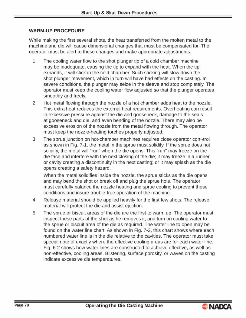
Page 78 Operating the Die Casting Machine
Start Up & Shut Down Procedures
WARM-UP PROCEDURE
While making the fi rst several shots, the heat transferred from the molten metal to the machine and die will cause dimensional changes that must be compensated for. The operator must be alert to these changes and make appropriate adjustments.
1. The cooling water fl ow to the shot plunger tip of a cold chamber machine may be inadequate, causing the tip to expand with the heat. When the tip expands, it will stick in the cold chamber. Such sticking will slow down the shot plunger movement, which in turn will have bad effects on the casting. In severe conditions, the plunger may seize in the sleeve and stop completely. The operator must keep the cooling water fl ow adjusted so that the plunger operates smoothly and freely.
2. Hot metal fl owing through the nozzle of a hot chamber adds heat to the nozzle. This extra heat reduces the external heat requirements. Overheating can result in excessive pressure against the die and gooseneck, damage to the seals at gooseneck and die, and even bending of the nozzle. There may also be excessive erosion of the nozzle from the metal fl owing through. The operator must keep the nozzle-heating torches properly adjusted.
3. The sprue junction on hot-chamber machines requires close operator con¬trol as shown in Fig. 7-1, the metal in the sprue must solidify. If the sprue does not solidify, the metal will "run" when the die opens. This "run" may freeze on the die face and interfere with the next closing of the die; it may freeze in a runner or cavity creating a discontinuity in the next casting; or it may splash as the die opens creating a safety hazard.
When the metal solidifi es inside the nozzle, the sprue sticks as the die opens and may bend the shot or break off and plug the sprue hole. The operator must carefully balance the nozzle heating and sprue cooling to prevent these conditions and insure trouble-free operation of the machine.
4. Release material should be applied heavily for the fi rst few shots. The release material will protect the die and assist ejection.
5. The sprue or biscuit areas of the die are the fi rst to warm up. The operator must inspect these parts of the shot as he removes it, and turn on cooling water to the sprue or biscuit area of the die as required. The water line to open may be found on the water line chart. As shown in Fig. 7-2, this chart shows where each numbered water line is in the die relative to the cavities. The operator must take special note of exactly where the effective cooling areas are for each water line. Fig. 6-2 shows how water lines are constructed to achieve effective, as well as non-effective, cooling areas. Blistering, surface porosity, or waves on the casting indicate excessive die temperatures.
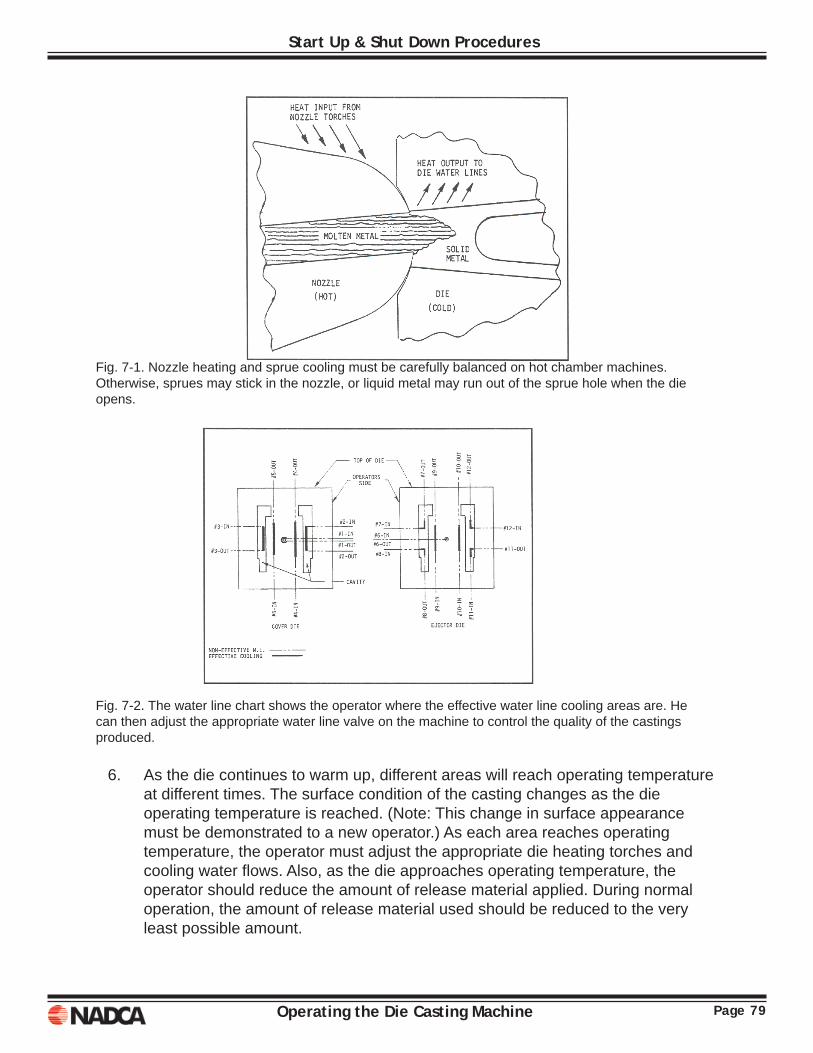
Page 79Operating the Die Casting Machine
Start Up & Shut Down Procedures
Fig. 7-1. Nozzle heating and sprue cooling must be carefully balanced on hot chamber machines. Otherwise, sprues may stick in the nozzle, or liquid metal may run out of the sprue hole when the die opens.
Fig. 7-2. The water line chart shows the operator where the effective water line cooling areas are. He can then adjust the appropriate water line valve on the machine to control the quality of the castings produced.
6. As the die continues to warm up, different areas will reach operating temperature at different times. The surface condition of the casting changes as the die operating temperature is reached. (Note: This change in surface appearance must be demonstrated to a new operator.) As each area reaches operating temperature, the operator must adjust the appropriate die heating torches and cooling water fl ows. Also, as the die approaches operating temperature, the operator should reduce the amount of release material applied. During normal operation, the amount of release material used should be reduced to the very least possible amount.
Page 80 Operating the Die Casting Machine
Start Up & Shut Down Procedures
7. Temperature stabilization of the die can also affect the size thickness of the die. If excessive fl ash develops or if the machine starts to "lock-up" slowly, the shut-height must be adjusted. Once the die stabilizes and is making good castings, the warm-up is complete. Only rarely are usable castings made during the warm-up period. Normal practice is to dispose of these castings to the remelt conveyor or tub.
Shut down ProceduresAny time the normal operating cycle of a die casting machine is interrupted, the many conditions that had stabilized during the normal operation begin to change. The longer the shut-down period, the more things become affected. Generally, shut-down periods can be described as cycle interruptions (up to ten minutes); temporary shut-down (up to two hours); or extended shut-downs (indefi nite period). Each type of shut-down requires a different action by the machine operator.
CYCLE INTERRUPTION
Short interruptions to the normal cycle occur when castings stick in the die and must be removed manually, solder build up in the die must be removed, excessive fl ashing requires tie bar adjustments, or when the die needs cleaning or extra lubrication. During these periods, the cooling water to the die must be turned off. If the cooling water continues to fl ow through the die, the die will cool down quickly. As a result, several scrap castings will be produced when normal cycling is resumed.
When the cooling water is no longer needed, it should be turned off at the main control valve. Settings of the individual water line valves should not be changed. For short-term cycle interruptions, it is preferable to turn off the cooling water fl ow two or three shots before the shut-down. When such a procedure is possible, it builds up a heat reserve in the die that will maintain the temperature during the shut-down.
TEMPORARY SHUT-DOWN
When shutting down the machine for less than two hours, the operator should:
1. Shut off die cooling water to die by turning off the main water valve. Do not change adjustment of individual water line valves.
2. Visually inspect machine for water leaks, hydraulic fl uid leaks, and lubrication failures. Any equipment defects should be reported.
3. Stop motors by depressing pump off or emergency stop buttons. Turn main disconnect switch to off position. Close the accumulator shut-off valve if it is not automatic.
4. Be sure die is clean. Remove any fl ash or other material from die. 5. Install and/or turn on die heating torches. 6. Increase heat to nozzle if machine is hot-chamber type.
Page 81Operating the Die Casting Machine
Start Up & Shut Down Procedures
EXTENDED SHUT-DOWN
When shutting down the machine for an extended period, the operator should execute the following procedures:
1. Shut off die cooling water. Close all individual water line valves. (When the machine is restarted, these water valves will have to be opened individually during the warm-up period.)
2. Inspect the machine for water leaks, oil leaks, lubrication problems, etc., and report any item requiring repair.
3. Inspect the last casting for any die maintenance-related defects such as fl ashing, ejector pins or cores, drags, solder, broken cores, etc. Any such defects should be reported to the operator's supervisor.
4. Clean fl ash and other material from die faces and oil die faces, including cavities, after the die cools to near room temperature to prevent rusting. When cleaning fl ash and other accumulations from the top of the die, care should be exercised to avoid pushing the material into the ejector mechanism or into water line holes.
5. Be sure die is open and shut off pump motors, turn main disconnect switch to off. Close the accumulator shut-off valve, if it is not automatic.
6. If the machine is the hot-chamber type, close the die, remove shot plunger from gooseneck and maintain heat to nozzle. (If the die is to be removed from the machine, turn nozzle heat off.)
7. Clean machine and machine area. Remove excess grease and oil, die release material, rags, paper, fl ash, and scrap castings. Hose down fl oor and scrape fl oor, if necessary, to remove stubborn material. Return all tools and other loose items to their storage areas.

Page 82 Operating the Die Casting Machine
Start Up & Shut Down Procedures
Operating the Die Casting Machine Page 83
Chapter 8NORMAL OPERATIONS
Normal operation will occupy the bulk of the operator's time and effort. His responsibility is to maintain continuous and uniform cycling of the machine and to perform the prescribed handling functions to the casting. Several basic operational sequences are used. The most common sequences are described in previous sections (see Chapter 5 - Controls Section, Cycle Start subsection).
Although any rule has exceptions, the operator must handle each casting. When the die casting machine is fully automatic, the operator usually operates the trim press. Otherwise he will remove each casting from the die casting machine, quench it in a water bath, and send it onto the trim operation. Sometimes the operator hand ladles the metal into cold-chamber machines. While performing these more-or-less mechanical duties, the operator must be alert to all the items discussed in the previous sections. The operator must make minor adjustments to the machine controls as required.
Two specifi c areas of responsibility are added, once normal operation begins. These responsibilities are: (I) care of the molten alloy, and (2) casting quality.
Page 84 Operating the Die Casting Machine
Normal Operations
METAL CARE
The metal in the holding furnace is very carefully mixed or alloyed. The amount of each element in the metal is precisely controlled. It is of the utmost importance that no foreign material gets into this metal because even tiny amounts of some elements have a very bad effect on quality. The following procedures should be followed to maintain this metal quality (the references to a ladle apply to the cold-chamber process):
1. Avoid any unnecessary turbulence or disturbance of the metal. 2. Ladle so as to break the surface of the metal as little as possible. 3. When ladling, use backward motion to skim metal dross with the ladle lip,
followed by a forward motion to dip metal from the skimmed area (see Fig 8-1). 4. Do not coat ladles or furnace pouring troughs with grease or oil. 5. Avoid broken streams when pouring. Pour from minimum heights. 6. Skim metal periodically, but not excessively. 7. Do not add wet or oily scrap to the holding furnace. 8. Do not burn paper, trash, or oil on the metal. 9. Keep all scrap and trimmings as clean as possible.10. Avoid excessive temperature changes. 11. Keep all iron tools and ladles that contact molten aluminum properly coated to
prevent iron from entering the aluminum.
Fig. 8-1. Care must be taken to insure that dross is not ladled into the cold chamber
Chemical or metallurgical changes may take place in some alloys, the aluminum alloys in particular, if they get too hot or too cold. Even if such changes do not occur, the temperature is very important to the casting process. Therefore, the operator must maintain the specifi ed metal temperature in the holding furnace. He must be alert when metal is added to his holding furnace. If additions change the temperature, he should inform his supervisor.
Page 85Operating the Die Casting Machine
Normal Operations
CASTING QUALITY
The operator must check each casting for obvious defects. Defective castings must be disposed of. In addition, he must occasionally make a thorough inspection of one or two shots. Minor variations in appearance from previous inspections indicate changes or "drifting" of the process (i.e., die temperature, metal temperature, nozzle temperature, shot speed). When these changes are detected, the operator must make compensating adjustments to the machine settings. Some of the most common casting defects and the techniques for their elimination are described in Chapter 9. The reader should observe that because of interrelationships, many suggested corrections apply to more than one defect. For this reason, the procedures for making corrections to machine conditions (for example die temperature) are not repeated in the discussion of each defect. Refer to Chapter 7 - Start-Up, and Warm-Up sections for details of such adjustments.

Page 86 Operating the Die Casting Machine
Normal Operations
Operating the Die Casting Machine Page 87
Chapter 9ELIMINATING CASTING DEFECTS
The conditions described in this chapter are common to the die casting process, and usually represent defective products that must be scrapped. It is impossible to illustrate all the defects that may be encountered, and it is equally unrealistic to describe accurately the exact corrective measures. The following illustrations show the new operator the general conditions he/she should watch for, and the suggested corrective measures provide a pattern for the operator to follow when he/she encounters a problem. Defects will be discussed as surface defects, defects that are visible; internal defects, defects that cannot be seen; and dimensional defects.
A major problem die casters have is that a particular defect may have different root causes or different defects have the same root cause. For example, we cannot say that all cracks are due to uneven ejection. Cracks could be due to shrinkage, or a cold die, or some other cause. On the other hand a casting may exhibit poor fi ll and chill and fl ow marks, all possibly due to a cold die.
Cold fl ow Cold shut Flow marks Cold Chill Severe chill Non-fi ll Poor-fi ll
This is by no means a complete list. The list may vary by shift, by plant by state or by country. Within a given plant, the list should be simplifi ed, with everyone understanding the terminology for a particular defect.
Laps Flow lines Swirls Knit lines Blisters Cracks Mis-run Solder

Page 88 Operating the Die Casting Machine
Eliminating Casting Defects
SURFACE DEFECTSSoldering. This condition, illustrated in Fig. 9-1, is the result of soldering of aluminum in the die casting alloy fusing with iron from the surface of the die cavity. Upon ejection, the casting tears away, leaving a layer that has bonded to the die. When soldering occurs, it may create additional problems such as cracking or bending of the casting, out of tolerance dimensions, depressed ejector pin marks in the casting and/or porosity within the casting.
Soldering may be caused by excessive metal temperature; incorrect die temperature (too hot or too cold), insuffi cient die release material, incorrect alloy, or too little draft. If the condition is severe or when other methods fail to remove the solder, it must be cleaned from the die. Caustic solutions provided for this purpose may be used, or the material may be polished out the die. It is recommended that a die maker, or other person with special training, polish the die cavity. If the polishing is not done properly, a rough die surface may be created that will increase the soldering condition. Care must also be exercised when increasing the amount of die release material applied to the soldering area. Excessive amounts of this material may create other defects such as porosity, chill, or blisters.
The purpose of die release is to provide a protective barrier between the aluminum and die steel. If the die release is ineffective, or casting conditions are such that the die release cannot wet the surface, conditions for soldering will be present.
Fig. 9-1. Soldering is the adhesion of the die cast metal to the die. Additional die release material, lower metal temperature, or a change in die temperature will usually reduce soldering.
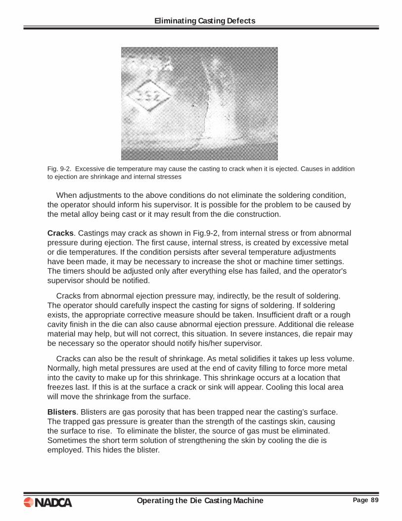
Page 89Operating the Die Casting Machine
Eliminating Casting Defects
Fig. 9-2. Excessive die temperature may cause the casting to crack when it is ejected. Causes in addition to ejection are shrinkage and internal stresses
When adjustments to the above conditions do not eliminate the soldering condition, the operator should inform his supervisor. It is possible for the problem to be caused by the metal alloy being cast or it may result from the die construction.
Cracks. Castings may crack as shown in Fig.9-2, from internal stress or from abnormal pressure during ejection. The fi rst cause, internal stress, is created by excessive metal or die temperatures. If the condition persists after several temperature adjustments have been made, it may be necessary to increase the shot or machine timer settings. The timers should be adjusted only after everything else has failed, and the operator's supervisor should be notifi ed.
Cracks from abnormal ejection pressure may, indirectly, be the result of soldering. The operator should carefully inspect the casting for signs of soldering. If soldering exists, the appropriate corrective measure should be taken. Insuffi cient draft or a rough cavity fi nish in the die can also cause abnormal ejection pressure. Additional die release material may help, but will not correct, this situation. In severe instances, die repair may be necessary so the operator should notify his/her supervisor.
Cracks can also be the result of shrinkage. As metal solidifi es it takes up less volume. Normally, high metal pressures are used at the end of cavity fi lling to force more metal into the cavity to make up for this shrinkage. This shrinkage occurs at a location that freezes last. If this is at the surface a crack or sink will appear. Cooling this local area will move the shrinkage from the surface.
Blisters. Blisters are gas porosity that has been trapped near the casting’s surface. The trapped gas pressure is greater than the strength of the castings skin, causing the surface to rise. To eliminate the blister, the source of gas must be eliminated. Sometimes the short term solution of strengthening the skin by cooling the die is employed. This hides the blister.

Page 90 Operating the Die Casting Machine
Eliminating Casting Defects
Lack of Fill. As shown in Fig. 9-3 and Fig. 9-4, this condition has three basic causes. They are inadequate metal in the gooseneck or cold chamber, low temperatures, or improper shot control settings. The metal level in the holding furnace of a hot chamber machine must be maintained above the gooseneck inlet ports. For cold chamber machines, the correct size ladle must be used and care must be taken to insure that the ladle is full for each shot. When an automatic ladle is being used, it must be properly adjusted to ladle exactly the correct amount of metal into the cold chamber.
Secondly, cold metal, cold die, or both may cause this defect. The temperatures should be checked and adjusted as necessary.
Third, lack of fi ll may be the result of slow shot speed. The shot control hydraulic valves should be opened the proper amount. As with all other machine malfunctions, if the shot is still slow and the valves are properly adjusted, the operator should notify his supervisor.
Lack of fi ll is also commonly known as poor fi ll and non-fi ll.
The next group of defects is categorized as fl ow defects. This means they are a result of the metal fl ow in the die cavity. The following list is a number of factors that affect fl ow defects. Following the list is an explanation of each of the factors and then a discussion of who is responsible for this factor and how it may be controlled.
Fig. 9-3.lnsuffi cient metal, cold metal, or a cold die can cause incomplete fi ll. The thin biscuit indicates an insuffi cient amount of metal was ladled into the cold chamber. Fig. 9-4. Lack of fi ll may be caused by slow shot speeds (long cavity fi ll times), which allows the metal to solidify before the cavity fi lls. However, when there is fl ash on the casting, insuffi cient metal is more likely the cause.
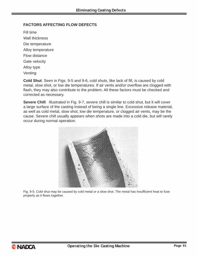
Page 91Operating the Die Casting Machine
Eliminating Casting Defects
FACTORS AFFECTING FLOW DEFECTS
Fill time Wall thickness Die temperature Alloy temperature Flow distance Gate velocity Alloy type Venting
Cold Shut. Seen in Figs. 9-5 and 9-6, cold shuts, like lack of fi ll, is caused by cold metal, slow shot, or low die temperatures. If air vents and/or overfl ow are clogged with fl ash, they may also contribute to the problem. All these factors must be checked and corrected as necessary.
Severe Chill. Illustrated in Fig. 9-7, severe chill is similar to cold shut, but it will cover a large surface of the casting instead of being a single line. Excessive release material, as well as cold metal, slow shot, low die temperature, or clogged air vents, may be the cause. Severe chill usually appears when shots are made into a cold die, but will rarely occur during normal operation.
Fig. 9-5. Cold shut may be caused by cold metal or a slow shot. The metal has insuffi cient heat to fuse properly as it fl ows together.
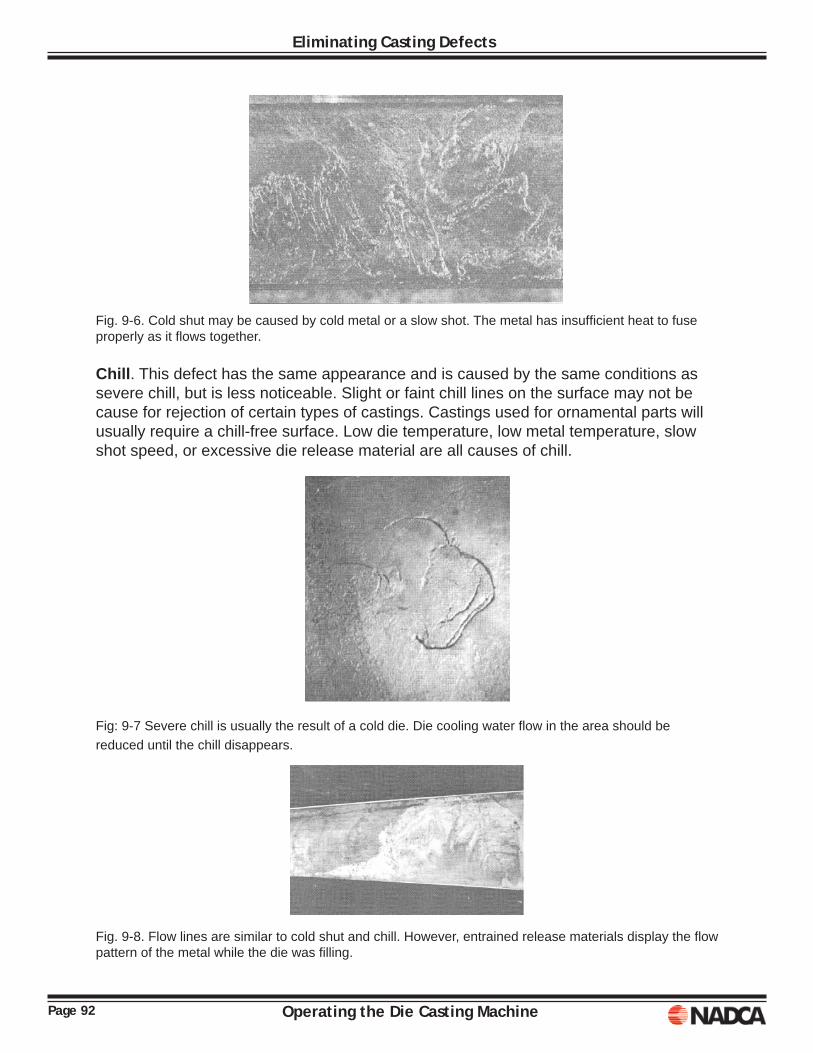
Page 92 Operating the Die Casting Machine
Eliminating Casting Defects
Fig. 9-6. Cold shut may be caused by cold metal or a slow shot. The metal has insuffi cient heat to fuse properly as it fl ows together.
Chill. This defect has the same appearance and is caused by the same conditions as severe chill, but is less noticeable. Slight or faint chill lines on the surface may not be cause for rejection of certain types of castings. Castings used for ornamental parts will usually require a chill-free surface. Low die temperature, low metal temperature, slow shot speed, or excessive die release material are all causes of chill.
Fig: 9-7 Severe chill is usually the result of a cold die. Die cooling water fl ow in the area should be reduced until the chill disappears.
Fig. 9-8. Flow lines are similar to cold shut and chill. However, entrained release materials display the fl ow pattern of the metal while the die was fi lling.
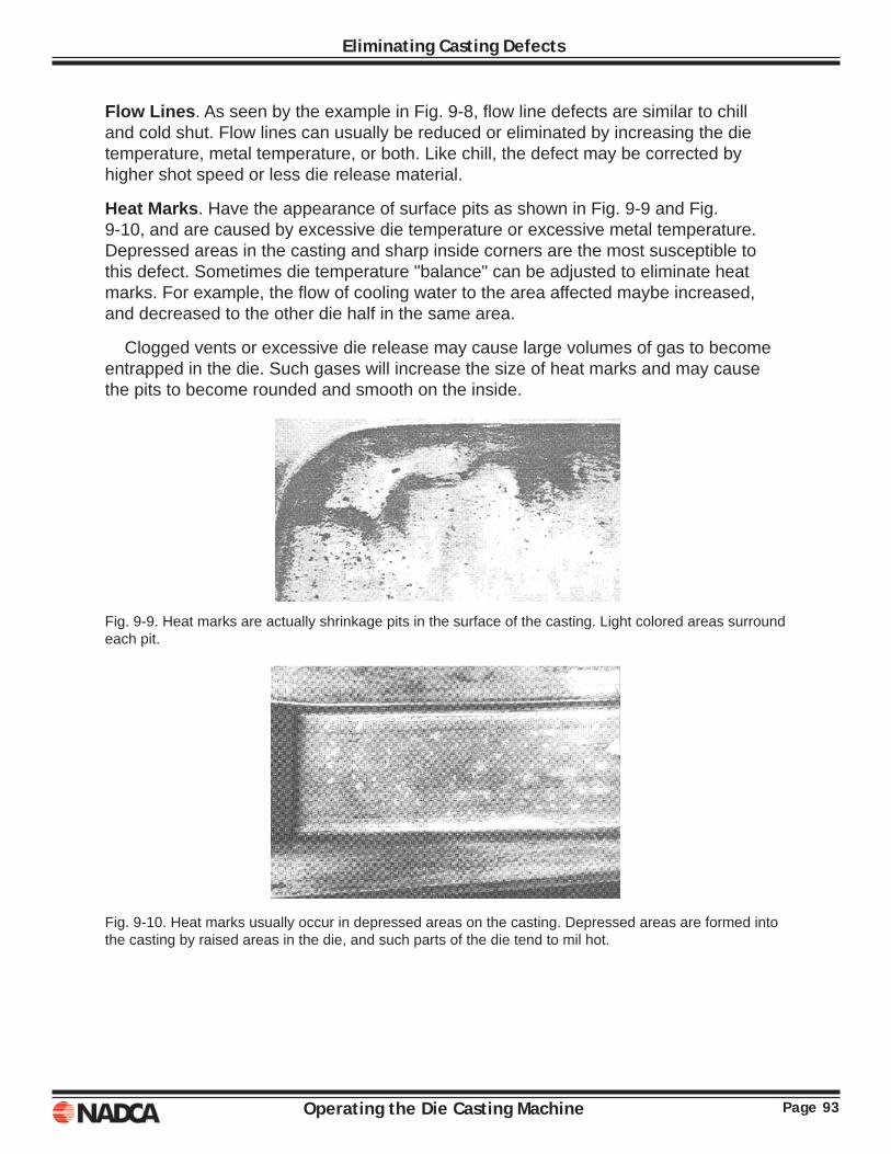
Page 93Operating the Die Casting Machine
Eliminating Casting Defects
Flow Lines. As seen by the example in Fig. 9-8, fl ow line defects are similar to chill and cold shut. Flow lines can usually be reduced or eliminated by increasing the die temperature, metal temperature, or both. Like chill, the defect may be corrected by higher shot speed or less die release material.
Heat Marks. Have the appearance of surface pits as shown in Fig. 9-9 and Fig. 9-10, and are caused by excessive die temperature or excessive metal temperature. Depressed areas in the casting and sharp inside corners are the most susceptible to this defect. Sometimes die temperature "balance" can be adjusted to eliminate heat marks. For example, the fl ow of cooling water to the area affected maybe increased, and decreased to the other die half in the same area.
Clogged vents or excessive die release may cause large volumes of gas to become entrapped in the die. Such gases will increase the size of heat marks and may cause the pits to become rounded and smooth on the inside.
Fig. 9-9. Heat marks are actually shrinkage pits in the surface of the casting. Light colored areas surround each pit.
Fig. 9-10. Heat marks usually occur in depressed areas on the casting. Depressed areas are formed into the casting by raised areas in the die, and such parts of the die tend to mil hot.
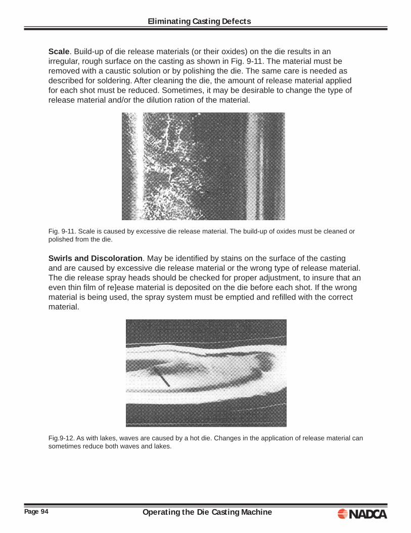
Page 94 Operating the Die Casting Machine
Eliminating Casting Defects
Scale. Build-up of die release materials (or their oxides) on the die results in an irregular, rough surface on the casting as shown in Fig. 9-11. The material must be removed with a caustic solution or by polishing the die. The same care is needed as described for soldering. After cleaning the die, the amount of release material applied for each shot must be reduced. Sometimes, it may be desirable to change the type of release material and/or the dilution ration of the material.
Fig. 9-11. Scale is caused by excessive die release material. The build-up of oxides must be cleaned or polished from the die. Swirls and Discoloration. May be identifi ed by stains on the surface of the casting and are caused by excessive die release material or the wrong type of release material. The die release spray heads should be checked for proper adjustment, to insure that an even thin fi lm of re]ease material is deposited on the die before each shot. If the wrong material is being used, the spray system must be emptied and refi lled with the correct material.
Fig.9-12. As with lakes, waves are caused by a hot die. Changes in the application of release material can sometimes reduce both waves and lakes.
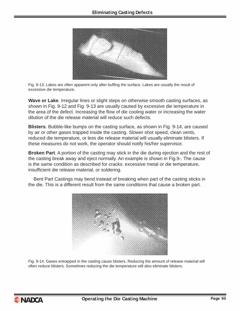
Page 95Operating the Die Casting Machine
Eliminating Casting Defects
Fig. 9-13. Lakes are often apparent only after buffi ng the surface. Lakes are usually the result of excessive die temperature.
Wave or Lake. Irregular lines or slight steps on otherwise smooth casting surfaces, as shown in Fig. 9-12 and Fig. 9-13 are usually caused by excessive die temperature in the area of the defect. Increasing the fl ow of die cooling water or increasing the water dilution of the die release material will reduce such defects.
Blisters. Bubble-like bumps on the casting surface, as shown in Fig. 9-14, are caused by air or other gases trapped inside the casting. Slower shot speed, clean vents, reduced die temperature, or less die release material will usually eliminate blisters. If these measures do not work, the operator should notify his/her supervisor.
Broken Part. A portion of the casting may stick in the die during ejection and the rest of the casting break away and eject normally. An example is shown in Fig.9-. The cause is the same condition as described for cracks: excessive metal or die temperature, insuffi cient die release material, or soldering.
Bent Part Castings may bend instead of breaking when part of the casting sticks in the die. This is a different result from the same conditions that cause a broken part.
Fig. 9-14. Gases entrapped in the casting cause blisters. Reducing the amount of release material will often reduce blisters. Sometimes reducing the die temperature will also eliminate blisters.
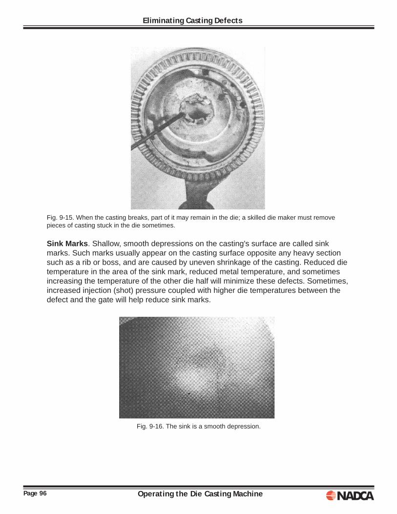
Page 96 Operating the Die Casting Machine
Eliminating Casting Defects
Fig. 9-15. When the casting breaks, part of it may remain in the die; a skilled die maker must remove pieces of casting stuck in the die sometimes.
Sink Marks. Shallow, smooth depressions on the casting's surface are called sink marks. Such marks usually appear on the casting surface opposite any heavy section such as a rib or boss, and are caused by uneven shrinkage of the casting. Reduced die temperature in the area of the sink mark, reduced metal temperature, and sometimes increasing the temperature of the other die half will minimize these defects. Sometimes, increased injection (shot) pressure coupled with higher die temperatures between the defect and the gate will help reduce sink marks.
Fig. 9-16. The sink is a smooth depression.
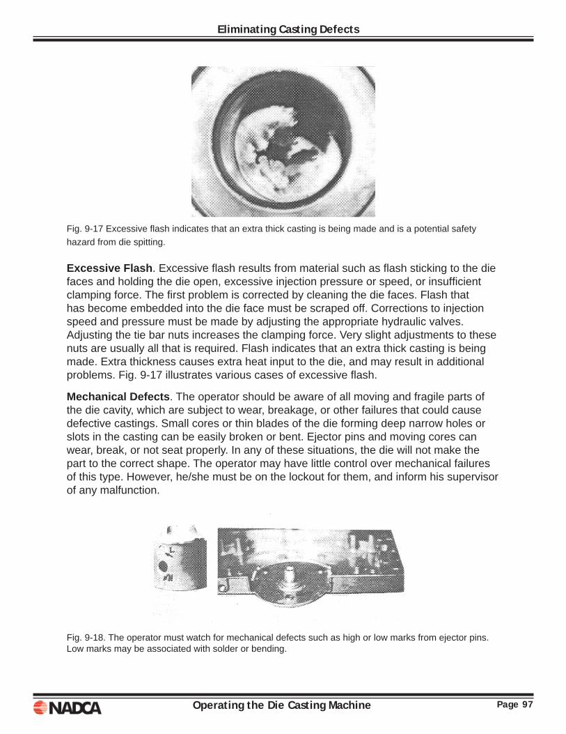
Page 97Operating the Die Casting Machine
Eliminating Casting Defects
Fig. 9-17 Excessive fl ash indicates that an extra thick casting is being made and is a potential safety hazard from die spitting.
Excessive Flash. Excessive fl ash results from material such as fl ash sticking to the die faces and holding the die open, excessive injection pressure or speed, or insuffi cient clamping force. The fi rst problem is corrected by cleaning the die faces. Flash that has become embedded into the die face must be scraped off. Corrections to injection speed and pressure must be made by adjusting the appropriate hydraulic valves. Adjusting the tie bar nuts increases the clamping force. Very slight adjustments to these nuts are usually all that is required. Flash indicates that an extra thick casting is being made. Extra thickness causes extra heat input to the die, and may result in additional problems. Fig. 9-17 illustrates various cases of excessive fl ash.
Mechanical Defects. The operator should be aware of all moving and fragile parts of the die cavity, which are subject to wear, breakage, or other failures that could cause defective castings. Small cores or thin blades of the die forming deep narrow holes or slots in the casting can be easily broken or bent. Ejector pins and moving cores can wear, break, or not seat properly. In any of these situations, the die will not make the part to the correct shape. The operator may have little control over mechanical failures of this type. However, he/she must be on the lockout for them, and inform his supervisor of any malfunction.
Fig. 9-18. The operator must watch for mechanical defects such as high or low marks from ejector pins. Low marks may be associated with solder or bending.
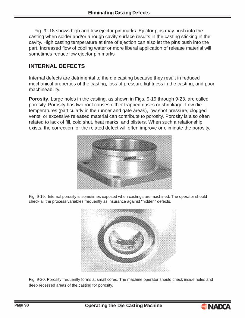
Page 98 Operating the Die Casting Machine
Eliminating Casting Defects
Fig. 9 -18 shows high and low ejector pin marks. Ejector pins may push into the casting when solder and/or a rough cavity surface results in the casting sticking in the cavity. High casting temperature at time of ejection can also let the pins push into the part. Increased fl ow of cooling water or more liberal application of release material will sometimes reduce low ejector pin marks
INTERNAL DEFECTS
Internal defects are detrimental to the die casting because they result in reduced mechanical properties of the casting, loss of pressure tightness in the casting, and poor machineability.
Porosity. Large holes in the casting, as shown in Figs. 9-19 through 9-23, are called porosity. Porosity has two root causes either trapped gases or shrinkage. Low die temperatures (particularly in the runner and gate areas), low shot pressure, clogged vents, or excessive released material can contribute to porosity. Porosity is also often related to lack of fi ll, cold shut. heat marks, and blisters. When such a relationship exists, the correction for the related defect will often improve or eliminate the porosity.
Fig. 9-19. lnternal porosity is sometimes exposed when castings are machined. The operator should check all the process variables frequently as insurance against "hidden" defects.
Fig. 9-20. Porosity frequently forms at small cores. The machine operator should check inside holes and deep recessed areas of the casting for porosity.
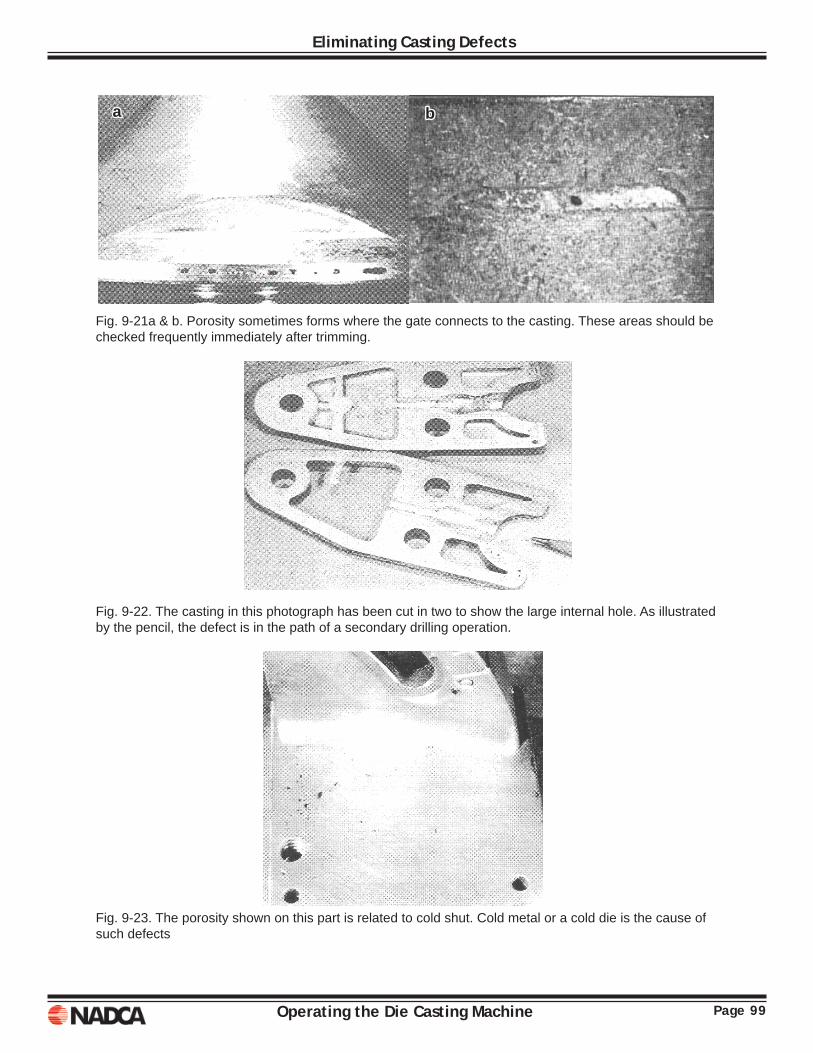
Page 99Operating the Die Casting Machine
Eliminating Casting Defects
Fig. 9-21a & b. Porosity sometimes forms where the gate connects to the casting. These areas should be checked frequently immediately after trimming.
Fig. 9-22. The casting in this photograph has been cut in two to show the large internal hole. As illustrated by the pencil, the defect is in the path of a secondary drilling operation.
Fig. 9-23. The porosity shown on this part is related to cold shut. Cold metal or a cold die is the cause of such defects
aa bb
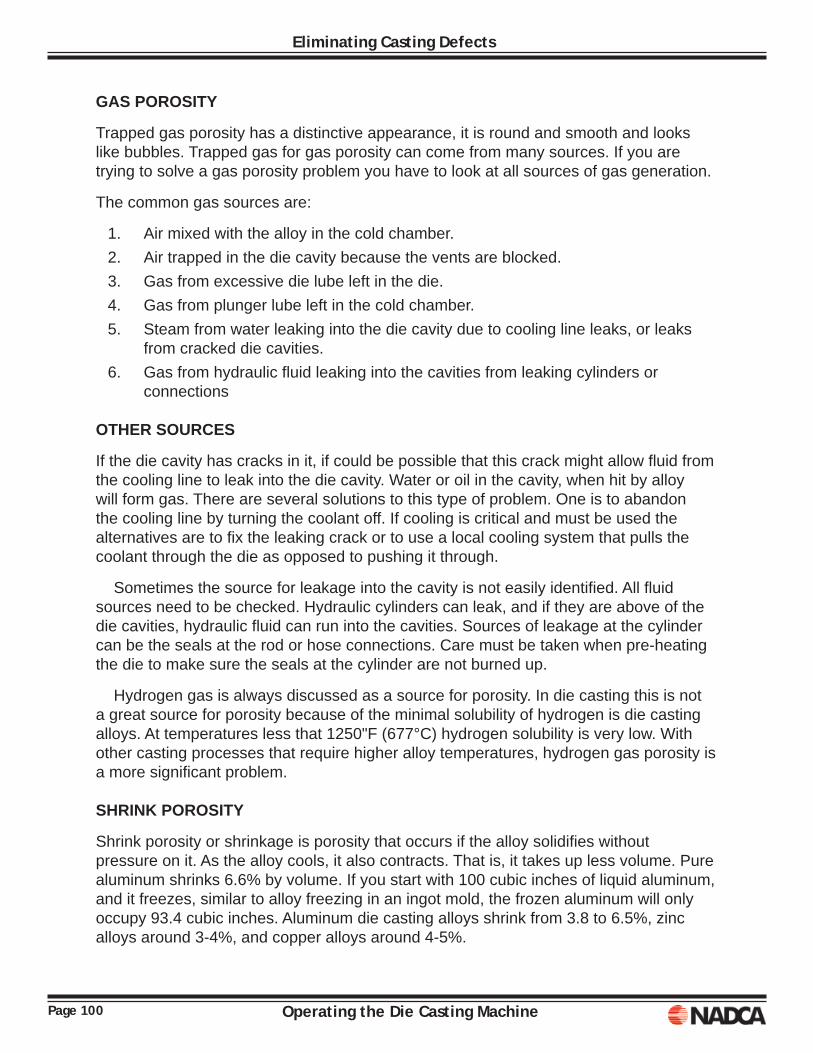
Page 100 Operating the Die Casting Machine
Eliminating Casting Defects
GAS POROSITY
Trapped gas porosity has a distinctive appearance, it is round and smooth and looks like bubbles. Trapped gas for gas porosity can come from many sources. If you are trying to solve a gas porosity problem you have to look at all sources of gas generation.
The common gas sources are:
1. Air mixed with the alloy in the cold chamber. 2. Air trapped in the die cavity because the vents are blocked. 3. Gas from excessive die lube left in the die. 4. Gas from plunger lube left in the cold chamber. 5. Steam from water leaking into the die cavity due to cooling line leaks, or leaks
from cracked die cavities. 6. Gas from hydraulic fl uid leaking into the cavities from leaking cylinders or
connections
OTHER SOURCES
If the die cavity has cracks in it, if could be possible that this crack might allow fl uid from the cooling line to leak into the die cavity. Water or oil in the cavity, when hit by alloy will form gas. There are several solutions to this type of problem. One is to abandon the cooling line by turning the coolant off. If cooling is critical and must be used the alternatives are to fi x the leaking crack or to use a local cooling system that pulls the coolant through the die as opposed to pushing it through.
Sometimes the source for leakage into the cavity is not easily identifi ed. All fl uid sources need to be checked. Hydraulic cylinders can leak, and if they are above of the die cavities, hydraulic fl uid can run into the cavities. Sources of leakage at the cylinder can be the seals at the rod or hose connections. Care must be taken when pre-heating the die to make sure the seals at the cylinder are not burned up.
Hydrogen gas is always discussed as a source for porosity. In die casting this is not a great source for porosity because of the minimal solubility of hydrogen is die casting alloys. At temperatures less that 1250"F (677°C) hydrogen solubility is very low. With other casting processes that require higher alloy temperatures, hydrogen gas porosity is a more signifi cant problem.
SHRINK POROSITY
Shrink porosity or shrinkage is porosity that occurs if the alloy solidifi es without pressure on it. As the alloy cools, it also contracts. That is, it takes up less volume. Pure aluminum shrinks 6.6% by volume. If you start with 100 cubic inches of liquid aluminum, and it freezes, similar to alloy freezing in an ingot mold, the frozen aluminum will only occupy 93.4 cubic inches. Aluminum die casting alloys shrink from 3.8 to 6.5%, zinc alloys around 3-4%, and copper alloys around 4-5%.
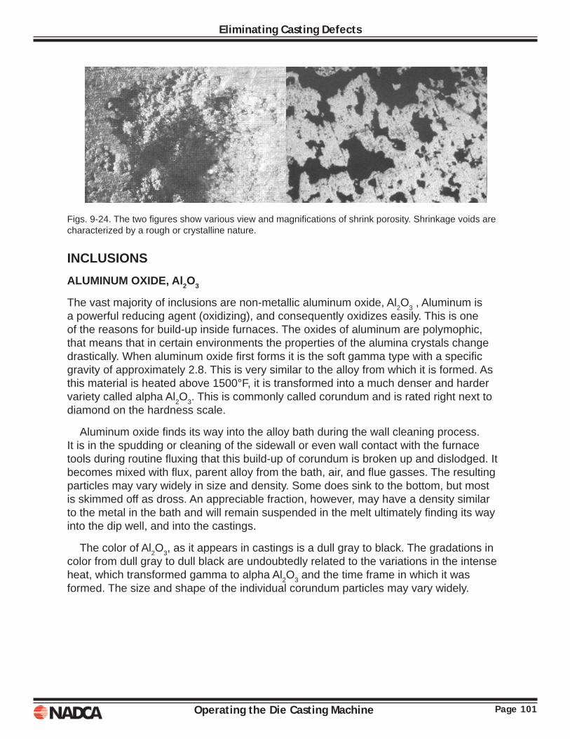
Page 101Operating the Die Casting Machine
Eliminating Casting Defects
Figs. 9-24. The two fi gures show various view and magnifi cations of shrink porosity. Shrinkage voids are characterized by a rough or crystalline nature.
INCLUSIONSALUMINUM OXIDE, Al2O3
The vast majority of inclusions are non-metallic aluminum oxide, Al2O3 , Aluminum is a powerful reducing agent (oxidizing), and consequently oxidizes easily. This is one of the reasons for build-up inside furnaces. The oxides of aluminum are polymophic, that means that in certain environments the properties of the alumina crystals change drastically. When aluminum oxide fi rst forms it is the soft gamma type with a specifi c gravity of approximately 2.8. This is very similar to the alloy from which it is formed. As this material is heated above 1500°F, it is transformed into a much denser and harder variety called alpha Al2O3. This is commonly called corundum and is rated right next to diamond on the hardness scale.
Aluminum oxide fi nds its way into the alloy bath during the wall cleaning process. It is in the spudding or cleaning of the sidewall or even wall contact with the furnace tools during routine fl uxing that this build-up of corundum is broken up and dislodged. It becomes mixed with fl ux, parent alloy from the bath, air, and fl ue gasses. The resulting particles may vary widely in size and density. Some does sink to the bottom, but most is skimmed off as dross. An appreciable fraction, however, may have a density similar to the metal in the bath and will remain suspended in the melt ultimately fi nding its way into the dip well, and into the castings.
The color of Al2O3, as it appears in castings is a dull gray to black. The gradations in color from dull gray to dull black are undoubtedly related to the variations in the intense heat, which transformed gamma to alpha Al2O3 and the time frame in which it was formed. The size and shape of the individual corundum particles may vary widely.
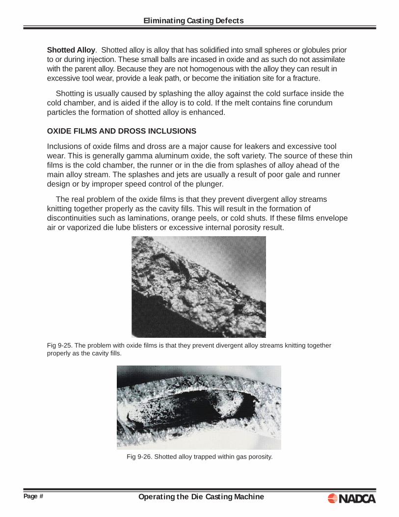
Page # Operating the Die Casting Machine
Eliminating Casting Defects
Shotted Alloy. Shotted alloy is alloy that has solidifi ed into small spheres or globules prior to or during injection. These small balls are incased in oxide and as such do not assimilate with the parent alloy. Because they are not homogenous with the alloy they can result in excessive tool wear, provide a leak path, or become the initiation site for a fracture.
Shotting is usually caused by splashing the alloy against the cold surface inside the cold chamber, and is aided if the alloy is to cold. If the melt contains fi ne corundum particles the formation of shotted alloy is enhanced.
OXIDE FILMS AND DROSS INCLUSIONS
Inclusions of oxide fi lms and dross are a major cause for leakers and excessive tool wear. This is generally gamma aluminum oxide, the soft variety. The source of these thin fi lms is the cold chamber, the runner or in the die from splashes of alloy ahead of the main alloy stream. The splashes and jets are usually a result of poor gale and runner design or by improper speed control of the plunger.
The real problem of the oxide fi lms is that they prevent divergent alloy streams knitting together properly as the cavity fi lls. This will result in the formation of discontinuities such as laminations, orange peels, or cold shuts. If these fi lms envelope air or vaporized die lube blisters or excessive internal porosity result.
Fig 9-25. The problem with oxide fi lms is that they prevent divergent alloy streams knitting together properly as the cavity fi lls.
Fig 9-26. Shotted alloy trapped within gas porosity.
Page #Operating the Die Casting Machine
Eliminating Casting Defects
SILICON CARBIDE REFRACTORIES
Silicon carbide refractories can fi nd their way into castings if furnace-clean¬ing practices are not maintained. SiC, silicon carbide is as damaging as corundum because of its hardness. It is encountered infrequently compared to corundum and may be distinguished by it very black, glass-like coloring. Their source can be chips from carbide crucibles or from grinding wheels used to remove soldering from the die surfaces.
FLUX
Flux inclusions are not usually recognized during a cursory visual inspection. A simple test to determine whether or not castings contain fl ux inclusions is to simply submerge the casting in city water overnight. If fl ux inclusions are present, they will grow crystals on the casting surface since fl ux is composed of salt. The corrosive products, which developed, appear as light mottling on all surfaces of the casting.
Flux inclusions can be identifi ed by a gray crystalline appearance, similar to rock salt. Flux inclusions are often associated with shrink voids, dross or hard spot inclusions. Flux inclusions will cause problems when coatings such as anodizing or alodining are applied, preventing adhesion. Shelf life of fi nished components with fl ux inclusions will be short; storing parts in a humid atmosphere will result in discoloration.
SLUDGE
Sludge is another inclusion considered to be a hard spot. Sludge is composed of complex inter-metallic compounds of AI-Si-Fe-Mn-Cr having melting points above the liquidus temperature of the alloy from which they are formed. Sludge is quite hard, and in a casting will surely damage cutter tooling. Under high magnifi cation the extremely fi ne primary crystals and their pentagonal shape are easily recognized as sludge.
The components necessary to form sludge are always present in alumi¬num die casting. The tendency to form sludge can be minimized by purchasing alloy that is low in the sludge forming ingredients as the fi rst step. The next step is to maintain good furnace temperature control.
You can check for sludging by raking the bottom of the furnace. Sludge is a silvery sandy material at the bottom of the furnace. It is best just to skim the material off the furnace bottom and discard it.
Since sludging depletes the iron in the bath, if the iron is not replaced, soldering can be expected with jobs that normally do not experience soldering problems. Also, reduced iron in the casting can result in hot cracking at die opening and ejection.
Each plant, each type of alloy being cast, each general type of casting, and each die will have its own set of operating characteristics. The operator must know how each process variable infl uences the quality from the particular die he/she is running. The defects listed above will help the operator evaluate his particular situation. The
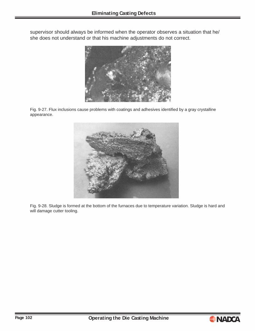
Page 102 Operating the Die Casting Machine
Eliminating Casting Defects
supervisor should always be informed when the operator observes a situation that he/she does not understand or that his machine adjustments do not correct.
Fig. 9-27. Flux inclusions cause problems with coatings and adhesives identifi ed by a gray crystalline appearance.
Fig. 9-28. Sludge is formed at the bottom of the furnaces due to temperature variation. Sludge is hard and will damage cutter tooling.

Page 103Operating the Die Casting Machine
Eliminating Casting Defects
NOTES:

Page 104 Operating the Die Casting Machine
Eliminating Casting Defects
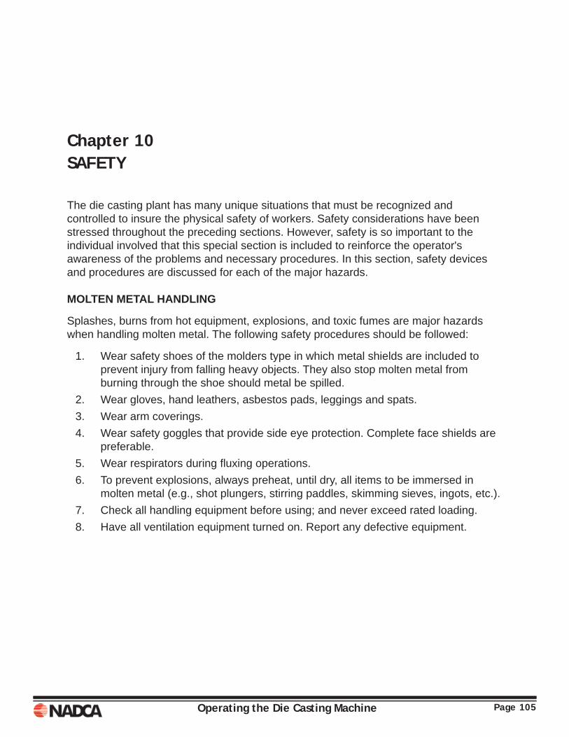
Operating the Die Casting Machine Page 105
Chapter 10SAFETY
The die casting plant has many unique situations that must be recognized and controlled to insure the physical safety of workers. Safety considerations have been stressed throughout the preceding sections. However, safety is so important to the individual involved that this special section is included to reinforce the operator's awareness of the problems and necessary procedures. In this section, safety devices and procedures are discussed for each of the major hazards. MOLTEN METAL HANDLING
Splashes, burns from hot equipment, explosions, and toxic fumes are major hazards when handling molten metal. The following safety procedures should be followed:
1. Wear safety shoes of the molders type in which metal shields are included to prevent injury from falling heavy objects. They also stop molten metal from burning through the shoe should metal be spilled.
2. Wear gloves, hand leathers, asbestos pads, leggings and spats. 3. Wear arm coverings. 4. Wear safety goggles that provide side eye protection. Complete face shields are
preferable. 5. Wear respirators during fl uxing operations. 6. To prevent explosions, always preheat, until dry, all items to be immersed in
molten metal (e.g., shot plungers, stirring paddles, skimming sieves, ingots, etc.). 7. Check all handling equipment before using; and never exceed rated loading. 8. Have all ventilation equipment turned on. Report any defective equipment.
Page 106 Operating the Die Casting Machine
Safety
DIE CASTING MACHINE OPERATION
Unexpected machine dosing, die spitting, molten metal splashing, and fi re from leaking hydraulic fl uid are the major hazards associated with the die casting machine. The following procedures are related to these problems:
1. Wear safety shoes of the molders type. 2. Wear gloves and arm coverings. 3. Wear goggles with side eye protection. 4. Be sure all machine safety shields are properly installed. 5. Be sure all machine safety controls and interlocks are working. 6. Be sure die is locking properly. Adjust tie bars to eliminate spitting from between
the dies. 7. Do not stand in line with die parting line. 8. Use tongs or hook to remove casting from die. 9. Close shot valves and block die open when working between die halves. Remove
shot plunger if machine is hot-chamber type. 10. Report or repair any hydraulic leak immediately. 11. Do not use fl ammable fl uids such as kerosene as die release material.
DIE SETTING
When changing a die casting machine set-up, the proximity of molten metals and the high temperatures of the die and machine add to the normal hazards of manipulating heavy items. When setting die casting dies:
1. Wear protective clothing described above. 2. Be sure machine is properly deactivated (shot valves closed, shot plunger
removed from hot-chamber, electrical panel locked off, etc.). 3. Use proper size eye bolts and seat the bolt shoulders properly against the die surface. 4. Use proper size chains. Avoid excessive spread of chains (see Fig. 6-3). 5. When two or more people are working together, special care must be taken to be
sure everyone is clear of the machine when operating the controls. 6. Be sure that all safety devices function properly when die setting is complete. 7. Clear all personnel from area before making fi rst shot on a newly-set die.
Page 107Operating the Die Casting Machine
Safety
HANDLING CASTINGS
When handling die castings, several precautions must be taken:
1. If the casting has not completely solidifi ed when the die opens, the liquid portion may blow or pop. This explosive action spits molten metal from between the partially-opened dies. The operator should stay clear of the die parting line until the die has opened about 2 inches. Once a blow is observed, the operator should adjust the machine controls to avoid a recurrence.
2. Castings are hot when fi rst removed from the die. Sometimes the castings are still hot enough to cause serious burns even after quenching. Gloves and other protective clothing should be worn at all times to prevent burns.
3. Untrimmed castings have fl ash that is sharp. This fl ash can easily cut through light clothing. Gloves and protective clothing should be worn to prevent cuts from fl ash.
4. When disposing castings to containers or conveyors, be sure that no one is in the way. If the casting strikes another person, that person could be cut, bruised, or burned. It should be noted that careful ha/Idling avoids damage to the casting as well as improving the safety condition.
HOUSEKEEPING
A die casting machine presents several housekeeping problems. Lubricating oil and grease build up, water often runs or sprays over the machine and fl oor, and molten metal spills accumulate. When these materials are not constantly removed, they quickly become slippery and, therefore, hazardous. To eliminate these and other hazards, the operator should do the following every day:
1. Return all loose equipment to its storage area. 2. Wipe excessive grease and oil from machine. 3. Clean fl oor. Scrape hardened materials to insure removal. 4. Remove fl ash and other foreign material from inside of safety doors and from die area. 5. Check fl oor for slippery areas and clean as required.
Page 108 Operating the Die Casting Machine
Safety
FIRE
Because of the combination of molten metal, gas torches, hydraulic fl uids, and lubricating greases and oils, there is a potential fi re hazard in a die casting department. Good housekeeping and equipment maintenance are the best fi re safety measures. All accumulation of oil, grease, or oily fi lms must be removed periodically. All hydraulic leaks must be reported immediately.
Eliminating accumulations of fl ammable materials coupled with good metal handling and die heating procedures, greatly reduces the potential fi re hazard.
Most serious industrial accidents are the result of someone having not observed an established safety rule. Operating the die casting machine can be a highly rewarding occupation; and if the operator learns and uses the safety procedures, there is little chance of injury.
Operating the Die Casting Machine Page A1
APPENDIX
Solutions to exercises………………………………………………………….A3
References………………………………………………………………………A5

Page A2 Operating the Die Casting Machine
Appendix
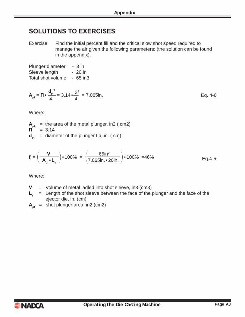
Page A3Operating the Die Casting Machine
Appendix
SOLUTIONS TO EXERCISES
Exercise: Find the initial percent fi ll and the critical slow shot speed required to manage the air given the following parameters: (the solution can be found in the appendix).
Plunger diameter - 3 in Sleeve length - 20 in Total shot volume - 65 in3 Eq. 4-6
Where: Apt = the area of the metal plunger, in2 ( cm2)Π = 3.14 dpt = diameter of the plunger tip, in. ( cm)
Eq.4-5
Where:
V = Volume of metal ladled into shot sleeve, in3 (cm3) Ls = Length of the shot sleeve between the face of the plunger and the face of the
ejector die, in. (cm) Apt = shot plunger area, in2 (cm2)
Apt = Π• dpt
2 = 3.14• 3
2 = 7.065in.
——— ——
4 4
fi = o V
p•100% = o 65in2
p•100% =46%
———— ———————
Apt•Ls 7.065in.•20in.

Page A4 Operating the Die Casting Machine
Appendix
Operating the Die Casting Machine Page A5
REFERANCES
1. Safety in Pressure Die Casting, Fourth Edition, 1970, Zinc Alloy Die Casters Association, 34 Berkeley Square, London, England
2. Die Casting Industry Safety Manual, American Die Casting Institute, Inc., 366 Madison Ave., New York, N.Y. 10017
3. H. K. Barton, Die Casting Die Design, The Machinery Publishing Co. Ltd., National House, West Street, Brighton 1, England
4. E. T. Lees, Quality Control in Die Casting, Die Casting Engineer, Jan-Feb. 1971, p. 26.
5. P. Thukkaram, Refresher Course on Die Casting. Lecture No.6, Zinc Alloy Die Casting Society, Safdarjung Enclave, New Delhi-16, India
6. E. Oberg and F. D. Jones, Machinery’s Handbook, The Industrial Press, 200 Madison Ave., New York, N.Y. 10016 .
7. S. D. Sanders, W. D. Kaiser, & P. D. Frost, Metalographic Analysis of Zinc Die Castings, Transactions. The Society of Die Casting Engineers, Inc. 1970, Paper 53.


3250 N. Arlington Heights Rd., Ste. 101Arlington Heights, IL 60004
P: 847.279.0001 F: 847.279.0002www.diecasting.org
NORTH AMERICAN DIE CASTING ASSOCIATION