operating manual - telemet · – attaching winch cable to anchor point . . . . 29 ... this...
TRANSCRIPT
Operating Manual
From WKU 824 10941.en
Drum winch

Printed in GermanyCopyright ®
Not to be reprinted, translated or duplicated either wholly or in part without written permission.
Technical details might not necessarily be exactly as described or illustrated in this operating manual.
Printed on environmentally compatible paper (bleached without chlorine, recyclable).
Kässbohrer Geländefahrzeug AGKässbohrerstrasse 11D-88471 Laupheim

400W10941.2.de 3/46
Ope
ratio
nCh
ecks
Use
Safe
tyTe
chni
cal
Dat
aO
pera
tion
Chec
ksU
seSa
fety
Tech
nica
l Dat
aO
verv
iew
Ope
ratio
nCh
ecks
Use
Safe
tyTe
chni
cal
Data
Ove
rvie
w
– Abbreviations used in this manual . . . . . . . . . . 5– Symbols used in this manual . . . . . . . . . . . . . . 5– Description . . . . . . . . . . . . . . . . . . . . . . . . . . 6– Intended use . . . . . . . . . . . . . . . . . . . . . . . . . 7– Basic rule . . . . . . . . . . . . . . . . . . . . . . . . . . . 7– Warning signs affixed to the equipment . . . . . 8
– Technical data . . . . . . . . . . . . . . . . . . . . . . . . 10– Fluids and lubricants . . . . . . . . . . . . . . . . . . 11
– Safety instructions for operation. . . . . . . . . . . . 13– Danger zone for persons . . . . . . . . . . . . . . . 13– Drum winch . . . . . . . . . . . . . . . . . . . . . . . . 13– Tensile loads - upper frame . . . . . . . . . . . . . 15– Auxiliary equipment. . . . . . . . . . . . . . . . . . . 14– Notes for the winch cable . . . . . . . . . . . . . . . . 16– Winch-cable designation . . . . . . . . . . . . . . . 16– Winch-cable usable life . . . . . . . . . . . . . . . . . 16
– Inspections and checks . . . . . . . . . . . . . . . . . . 25– Inspection work before operation . . . . . . . . . 25– Greasing guide roll . . . . . . . . . . . . . . . . . . . 27
OVERVIEW
TECHNICAL DATA
SAFETY
CHECKS
CONTENTS

4/46400W10941.2.de
– Moving the vehicle into position . . . . . . . . . 28– Attaching winch cable to anchor point . . . . 29– Checking operation of pulling-force regulator 30– Operating the drum winch . . . . . . . . . . . . . . 32– Turning the PistenBully . . . . . . . . . . . . . . . . 33– Driving downhill . . . . . . . . . . . . . . . . . . . . . 34– Driving uphill . . . . . . . . . . . . . . . . . . . . . . . 35– Relieving tension on the winch cable . . . . . . 36– Ceasing operation . . . . . . . . . . . . . . . . . . . . 37– STOP button . . . . . . . . . . . . . . . . . . . . . . . . . . . 39– Tilting the load platform . . . . . . . . . . . . . . . . . 40– Installing/removing the drum winch . . . . . . . . 43– Tilting the winch boom . . . . . . . . . . . . . . . . . . 42
OPERATION
CONTENTS

400W10941.2.de 5/46
Ope
ratio
nCh
ecks
Use
Safe
tyTe
chni
cal
Dat
aO
pera
tion
Chec
ksU
seSa
fety
Tech
nica
l Dat
aO
verv
iew
Ope
ratio
nCh
ecks
Use
Safe
tyTe
chni
cal
Data
Ove
rvie
w
This operating manual provides information about:
how to handle, maintain and care for your drum winch.
important instructions concerning correct and economi-cal operation.
warnings so that you recognise dangers in good time and avoid them.
e.g. . . . . . = for example
MA . . . . . = tightening torque
SP No. . . . = spare part order number
sec. . . . . . = seconds
min. . . . . . = minimum
This symbol draws attention to practical tips.
Important notes!Possibility of damage to the machine or its immediate sur-roundings.
ABBREVIATIONS USED IN THIS MANUAL
i
SYMBOLS USED IN THIS MANUAL
DANGER!
Direct and imminent danger threatening life and limb unless appropriate precautions are taken.
WARNING!
Potentially highly dangerous situation!Danger to life and limb unless appropriate precau-tions are taken
CAUTION!
Dangerous situation!Could lead to injury unless appropriate precautions are taken
INTRODUCTION

6/46400W10941.2.de
The capstan winch is an aid to traction
It helps to stabilise the moving vehicle.
The drum winch is not a rescue winch.
The PistenBully's fourth pump pressurises the hydraulic fluid for the winch drive.
The winch is driven by the pair of multi groove drums 1.
The windlass 2 keeps the cable under a defined tension.
The pull on the cable can be varied by means of pulling-force regulator 3.
Usable cable length 1000 meters.
.
DESCRIPTION
21
3
INTRODUCTION

400W10941.2.de 7/46
Ope
ratio
nCh
ecks
Use
Safe
tyTe
chni
cal
Dat
aO
pera
tion
Chec
ksU
seSa
fety
Tech
nica
l Dat
aO
verv
iew
Ope
ratio
nCh
ecks
Use
Safe
tyTe
chni
cal
Data
Ove
rvie
w
The drum winch:
is an accessory for the PistenBully.
must be operated on the platform of the PistenBully.
Use the drum winch only:
to secure the PistenBully to prevent it slipping on de-scents.
to aid the traction of the PistenBully on ascents.
when it is in perfectly safe operating condition.
If you wish to use the equipment for any other purpose, you must obtain prior written approval from the manufacturer.
Always comply with the operating instructions for the drum winch and the PistenBully 400.
An employee of Kässbohrer Geländefahrzeug AG or a person expressly appointed by the company has:
commissioned the equipment.
instructed the driver in the use of a drum winch.
instructed the personnel for checking and maintenance work.
When drivers change the owner-operator is responsible for providing correct and adequate instruction for the new driver.
INTENDED USE BASIC RULE
BASIC SAFETY INSTRUCTIONS

8/46400W10941.2.de
Strict compliance with the warning signs affixed to the drum winch is mandatory.
Warning signs must be replaced immediately if lost or damaged.
Warning sign:
Location: Winch frameSP No. 8.762.638.058E
WARNING!
Rotating components can crush fingers and hands.Keep well clear of component until it has come to a complete standstill.
WARNING SIGNS AFFIXED TO THE EQUIPMENT
BASIC SAFETY INSTRUCTIONS

400W10941.2.de 9/46
Ope
ratio
nCh
ecks
Use
Safe
tyTe
chni
cal
Dat
aO
pera
tion
Chec
ksU
seSa
fety
Tech
nica
l Dat
aO
verv
iew
Ope
ratio
nCh
ecks
Use
Safe
tyTe
chni
cal
Data
Ove
rvie
w
Warning sign:
Location: Winch frameSP No. 8.762.651.000 E
WARNING!
Danger: Slackening of threaded fasteners.Strict compliance with the tightening torques as stated on the winch mounting is essential.
BASIC SAFETY INSTRUCTIONS

10/46400W10941.2.de
PistenBully 400 WSpeed
Dimensions
With drum winch . . . . . . . . . . . . . . . . 0 - 20 km/h Height with PistenBully . . . . . . . . . . . . 3280 mm
Drum winch in operationspeed . . . . . . . . . . . . . . . . . . . . . . . . . 0 - 17 km/h
With winch boom lowered . . . . . . . . . . 2910 mm
Fuel consumption . . . . . . . . . . . . . . . at least 19 l/h Winching drum system
Weight Type TL40 60 AH 1050/11 . . . . . . . . . . Plumettaz
Drum winch . . . . . . . . . . . . . . . . . . . . 1,900 kg Winch pump
Without cable . . . . . . . . . . . . . . . . . . 1,000 kg Type A4 VG90 . . . . . . . . . . . . . . . . . . Hydromatik
TECHNICAL DATA

Ope
ratio
nCh
ecks
Use
Safe
tyTe
chni
cal
Dat
aO
pera
tion
Chec
ksU
seSa
fety
Tech
nica
l Dat
aO
verv
iew
400W10941.2.de 11/46400W10941.2.de 11/46
Ope
ratio
nCh
ecks
Use
Safe
tyTe
chni
cal
Dat
aO
verv
iew
.
Designation Grade Capacity Interval between changes
Gear oil Fully synthetic gear oil Base: Polyalphaoleofin (PAO)Classification: DIN 51517 T3 CLP HCViscosity class: ISO VG 220
10 litres every 100 / 400 hoursAt least: once a yearevery 800 hours100 / 400 hours after W4 mainte-nance
Fully synthetic gear oilBase: Polyalphaoleofin (PAO)Classification: API GL 5/ MIL-L-2105 B/CViscosity class: SAE 75W140
Windlass gear
Gear Slewing gear drive
Polyalphaoleofin (PAO)Classification: DIN 51517 T3 CLP HCViscosity index: ISO VG 150
ISO VG 220 (summer)
Polyalphaoleofin (PAO)Classification: API - GL 4 Viscosity class: SAE 75 W 90
0.5 litre
0.9 litreSlewing-gear drive
after 100 operating hoursAt least: once a yearevery 600 hoursevery 3000 hours100 operating hours after W4 maintenance
Lube grease for cable guide roll and slewing gear
Calcium saponified grease KP 2 G-30 DIN 51502AVIACAL 2 LD - 1 kg - 0.946.047.000
Cable guide roll:dailySlewing gear: every 100 hours
FLUIDS AND LUBRICANTS

NOTES
12/46 400W10941.2.de

400W10941.2.de 13/46
Ope
ratio
nCh
ecks
Use
Safe
tyTe
chni
cal
Data
Ove
rvie
w
Risk of fatal injury:Before using the drum winch, make sure there is no-one in the danger zone.
Close off the ski slope.
Before using the drum winch, secure thedanger zone "S": the size of this zone depends on the length of the cable.
WARNING!
Risk of fatal injury if winch cable snaps.On a slope that does not tail off into a flat of suffi-cient size to stop the vehicle. Adopt suitable safety measures.
Additional safety measures:- Snow wall- Stopper nets- Flashing beacons
Comply with all applicable national regulations.
Note that the cable can whip over several meters as the vehicle moves over surface irregularities on the slope.
Damage to capstan drum.Due to driving with capstan winch switched off and winch cable engaged.
DANGER ZONE FOR PERSONS
DRUM WINCH
SAFETY INSTRUCTIONS FOR OPERATION

14/46400W10941.2.de
Risk of collision.When passing underneath:- a taut cable- a high-voltage overhead cable- a drag lift- a cable-car line
The anchor point for the load hook must be capable of withstanding a tensile force of at least 150 kN.
The mount for the load hook must be of non-swivel de-sign.
Operation of the winch is permissible only when the winch cover is closed.
The auxiliary equipment of Kässbohrer Geländefahrzeug AG has been approved for winch operation.
Risk of collision between auxiliary equipment and winch ca-ble.Always allow adequate clearance from the winch cable when raising the auxiliary equipment.
Risk of collision between front snow blower and winch boom.The front snow blower must be suitable for a vehicle fitted with a winch.
Use only winch cable from Kässbohrer Geländefahrzeug AG.
AUXILIARY EQUIPMENT
SAFETY INSTRUCTIONS FOR OPERATION

400W10941.2.de 15/46
Ope
ratio
nCh
ecks
Use
Safe
tyTe
chni
cal
Data
Ove
rvie
w
High tensile load on the upper frame.Note pulling-force control when changing the direction of the PistenBully relative to the anchor point.
Change of direction up to 300: (winch boom / outside mirrors)
Set pulling-force regulator to a maximum of 4 metric tons.
Change of direction more than 300:
Set pulling-force regulator to a maximum of 2.0 metric tons.
TENSILE LOADS - UPPER FRAME
Pulling-force regulator
Pulling-force regulator
SAFETY INSTRUCTIONS FOR OPERATION

16/46400W10941.2.de
Winch-cable designation:
Winch-cable diameter 11 mm
Cable length 1050 metres.
Usable cable length 1000 metres. The rest of the winch cable is marked red.
Use only Kässbohrer winch cables.
Always comply with all applicable national safety regulations for cable monitoring
Transport winch cable
Depends on:
the load on the cable
the number of turns over the drums.
handling and maintenance.
WINCH-CABLE DESIGNATION WINCH-CABLE USABLE LIFE
SAFETY INSTRUCTIONS FOR OPERATION

400W10941.2.de 17/46
Ope
ratio
nCh
ecks
Use
Safe
tyTe
chni
cal
Data
Ove
rvie
w
The winch cable is maintenance-free.
Winch cable: - Do not re-grease.- Do not apply preserving agents.- Do not clean with a high-pressure cleaner.- Use only a dry cloth to wipe off.
Winch-cable condition:
5 wires are broken over a length of 66 mm.
10 wires are broken over a length of 110 mm.
one strand is broken.
the cable is wavy (corkscrew effect).
the cable is kinked or crushed.
Situational help
A wire is broken on the winch cable:
Slightly raise the broken ends and bend them back and forth until they break off at the root of the strand.
Make sure that there are no projecting wires.
Do not cut off broken wires.
THE WINCH CABLE IS DUE FOR REPLACEMENT IF:
SAFETY INSTRUCTIONS FOR OPERATION
18/46400W10941.2.de
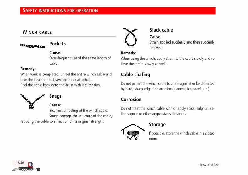
Pockets
Cause:Over-frequent use of the same length of cable.
Remedy:When work is completed, unreel the entire winch cable and take the strain off it. Leave the hook attached.Reel the cable back onto the drum with less tension.
Snags
Cause:Incorrect unreeling of the winch cable.Snags damage the structure of the cable,
reducing the cable to a fraction of its original strength.
Slack cableCause:Strain applied suddenly and then suddenly relieved.
Remedy:When using the winch, apply strain to the cable slowly and re-lieve the strain slowly as well.
Cable chafing
Do not permit the winch cable to chafe against or be deflected by hard, sharp-edged obstructions (stones, ice, steel, etc.).
Corrosion
Do not treat the winch cable with or apply acids, sulphur, sa-line vapour or other aggressive substances.
Storage
If possible, store the winch cable in a closed room.
WINCH CABLE
SAFETY INSTRUCTIONS FOR OPERATION

400W10941.2.de 19/46
Ope
ratio
nCh
ecks
Use
Safe
tyTe
chni
cal
Data
Ove
rvie
w
Load hook
The winch cable is fitted with a load hook with safety lock. In order to help prevent the cable from unravelling, the load hook is attached to the cable without a swivel.
The anchor cable (belay) is between the anchor point and the load hook of the winch cable.
Always use a double cable or twist stopper between the anchor cable and the load hook of the winch cable.
This will prevent the winch cable from unravelling.
WINCH CABLE LOAD HOOK
ANCHOR CABLE
SAFETY INSTRUCTIONS FOR OPERATION

20/46400W10941.2.de
1 Slewing-gear holding brakelights up when holding brake is applied.Intermittent warning buzzer sounds when cable is be-ing reeled in.
2 Winch boom warning indicatorlights up when winch boom not locked.Intermittent warning buzzer sounds.
3 Pulling-force indicator
4 Cable-strand warning indicator- is not a substitute for visual inspection of the cable.- lights up if winch cable is defective.Warning buzzer sounds intermittently.- Cease operation and ascertain the cause of the problem.
5 Cable-reel warning indicator- lights up when cable unreeled to maximum usable length.- lights up if winch cable winding is faulty.Warning buzzer soundsTurn immediately and check winch cable winding (see Driving uphill).
6 Electronic pulling-force controllights up when electronic pulling-force control is OFF
7 Operating hours counter for winch
INSTRUMENT DISPLAYS
1
2
34
5
6
7
USE

400W10941.2.de 21/46
Ope
rati
onCh
ecks
Use
Safe
tyTe
chni
cal
Data
Ove
rvie
wO
pera
tion
Chec
ksU
seSa
fety
Tech
nica
l Da
taO
verv
iew
1 Active winch
Rocker switch ON = A (indicator light shows)
To help prevent overstraining the winch boom it is advisable to turn the PistenBully and switch off the active winch.
The winch's lateral pulling force depends on the steering an-gle and the pulling force of the winch.
Driving with active winch
When to switch on the active winch:
- PistenBully drifts off-line when crossing a steep slope.
Example: Driving forward and steering to right B: Winch-boom lateral pulling force A activated in direction indicated by arrow. The PistenBully turns more easily and holds its heading.
1
11
BA
USE

22/46400W10941.2.de
2 Pulling-force regulator for winch cableadjustable between 0 - 40 kN
Latching rocker switch
Rocker switch
Rocker switch
Pushbutton
WINCH CABLE - REEL IN / UNREELTop section pressed = Reel in cableCentred = Winch OFFBottom section pressed = Unreel
SLEWING GEAR HOLDING BRAKETop section pressed = Apply brakeBottom section pressed = Release brake
2
P
SWIVEL WINCH BOOMTop section pressed = Swivel rightBottom section pressed = Swivel left
RESET ACOUSTIC WARNING FOR STRAND MONITOR(see Uphill driving).
Function Joystick
RAISE
USE

400W10941.2.de 23/46
Ope
rati
onCh
ecks
Use
Safe
tyTe
chni
cal
Data
Ove
rvie
wO
pera
tion
Chec
ksU
seSa
fety
Tech
nica
l Da
taO
verv
iew
FunctionFront blade
Joystick electric / hydraulic
Joystick position Pushbutton / rocker switch
RAISE - LOWER
A - Lower
B - Raise
Floating position
TILT
C - Left
D - Right
ROLL
A - Forward
B - Back
1.1
1.1
USE

24/46400W10941.2.de
FunctionFront blade
Joystick electric / hydraulic
Joystick position Pushbutton orrocker switch
SWIVEL
C - Swivel left.
D - Swivel right.1.1
WING, LEFT
A - Move wing in.
B - Move wing out.1.2
WING, RIGHT
C - Move wing in.
D - Move wing out.1.2
1.1
1.2
1.2
USE

400W10941.2.de 25/46
Ope
rati
onCh
ecks
Use
Safe
tyTe
chni
cal
Data
Ove
rvie
wO
pera
tion
Chec
ksU
seSa
fety
Tech
nica
l Da
taO
verv
iew
Remove snow and ice from the winch.
Check winch fasteners 1.Tightening torque MA = 500 Nm.
Check operation of slewing-gear holding brake.
Check that hydraulic lines and connectors are free of leaks and check for chafing.
Check that the cable guide arm moves freely on the wind-lass.
Clean viewing screen for winch cable winding.
Check operation of safety lock 3.
Check ease of movement of the cable relay rollers in the winch boom and of the cable guide arm..
1. CHECKS BEFORE OPERATION 1
3
OPERATION

26/46400W10941.2.de
Checking winch boom warning indicator
Diesel-engine ignition ON.
Set pulling-force regulator 2 to 0.
Pull pin 4 and open the toggle.
The winch boom warning indicator lights up. The warning buzzer sounds.
Checking cable-reel warning indicator
Diesel-engine ignition ON.
Press toggle 6 until switch contact 7 is open.
The cable-reel warning indicator lights up. The warning buzzer sounds.
Set the rocker switch to the "reel in cable" posi-tion.
2
5
4
Set the rocker switch to the "reel in cable" position.
76
OPERATION

400W10941.2.de 27/46
Ope
rati
onCh
ecks
Use
Safe
tyTe
chni
cal
Data
Ove
rvie
wO
pera
tion
Chec
ksU
seSa
fety
Tech
nica
l Da
taO
verv
iew
Greasing guide roll
Grease nipple 9 and shaft 8 with special grease.
Approved special grease:Calcium saponified greaseSpecification: Aviacal 2 LD, KP2K-30 DIN 51502
Special greases are not compatible with each other.When changing to another special grease, grease entire guide roll.
You can now start moving the vehicle into position.
9
8
OPERATION
28/46400W10941.2.de
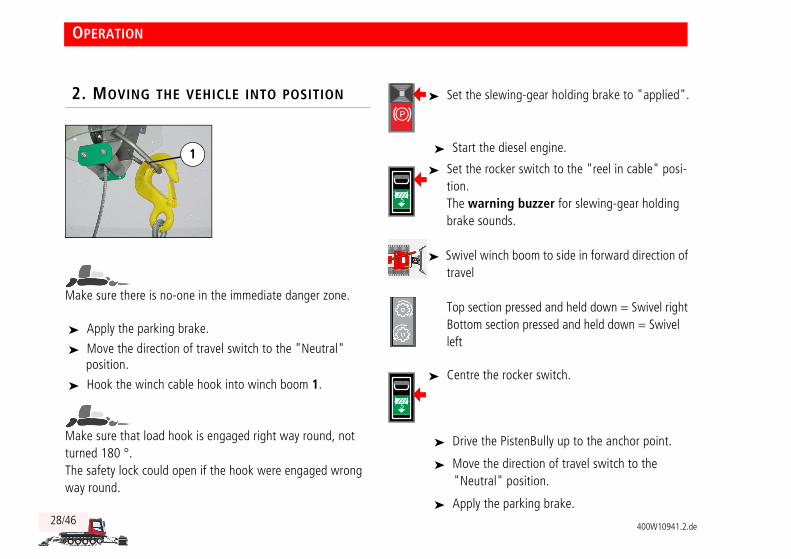
Make sure there is no-one in the immediate danger zone.
Apply the parking brake.
Move the direction of travel switch to the "Neutral" position.
Hook the winch cable hook into winch boom 1.
Make sure that load hook is engaged right way round, not turned 180 °.The safety lock could open if the hook were engaged wrong way round.
Start the diesel engine.
Drive the PistenBully up to the anchor point.
Move the direction of travel switch to the "Neutral" position.
Apply the parking brake.
2. MOVING THE VEHICLE INTO POSITION
1
Set the slewing-gear holding brake to "applied".
Set the rocker switch to the "reel in cable" posi-tion.The warning buzzer for slewing-gear holding brake sounds.
Swivel winch boom to side in forward direction of travel
Top section pressed and held down = Swivel rightBottom section pressed and held down = Swivel left
Centre the rocker switch.
P
OPERATION

Ope
rati
onCh
ecks
Use
Safe
tyTe
chni
cal
Data
Ove
rvie
w
400W10941.2.de 29/46
Ope
rati
onCh
ecks
Use
Safe
tyTe
chni
cal
Data
Ove
rvie
w
The vehicle is now in position.
You can now start attaching the winch cable to the anchor point.
Check that indicator light for winch boom 4 is OFF.
Set pulling-force regulator 2 to 0.
The indicator light is ON.
Set the rocker switch to the "reel in cable" position.The warning buzzer for slewing-gear holding brake sounds.
Swivel winch boom toward the anchor pointTop section pressed = Swivel rightBottom section pressed = Swivel left
Centre the rocker switch.The drum winch is out of action.
3. ATTACHING WINCH CABLE TO ANCHOR POINT
The indicator light is ON.Electronic pulling-force control is OFF
Move the rocker switch to the "unreel" position, overcoming the detent.
24
OPERATION

30/46400W10941.2.de
The drive discs rub against the winch cable. This causes heat-ing and accelerated wear.Remedy: Work quickly and smoothly when engaging the winch cable.
Disengage the load hook from the winch boom and pull it quickly to the anchor point.
Secure the load hook to the anchor point.
You can now proceed to the function check of the pulling-force regulator.
High load on winch boom.Keep far enough away from the anchor point to ensure that the high pulling force does not draw the winch boom down or up.
Check: The pulling-force regulator must be at 0, otherwise the cable cannot be reeled in.
Visual inspection: The 2nd cable intake roll must also turn. Adverse weather can freeze the roll and prevent it from turning.
Centre the rocker switch.
4. FUNCTION CHECK OF PULLING-FORCE REGULATOR
Set the rocker switch to the "reel in cable" posi-tion.The intermittent warning buzzer for slewing-gear holding brake sounds.
116
OPERATION

Ope
rati
onCh
ecks
Use
Safe
tyTe
chni
cal
Data
Ove
rvie
w
400W10941.2.de 31/46
Ope
rati
onCh
ecks
Use
Safe
tyTe
chni
cal
Data
Ove
rvie
w
Continue turning the pulling-force control until the setting reaches a maximum of 5 kN. - The winch cable is tensioned.
Press the accelerator to increase the speed of the diesel engine to approximately 1200 rpm.
Slowly turn the pulling-force regulator to its limit stop.
Back off the pulling-force regulator as far as it will go.Pulling force is reduced only to a minimum of 10 kN.
This completes the function test of the pulling-force regulator.
You can now start operating the drum winch.
Slowing turn the pulling-force regulator in the direction indicated by the arrow until the cable reels in.
– The symbol flashes.
Set the slewing-gear holding brake to "released".The symbol lights up.
– The brake indicator light is OFF
P
P
Slowing turn the pulling-force regulator past 10 kN.Pulling force decreases slightly.
– The indicator light is OFF.
– The indicator must show a pulling-force reading of 38 - 40 kN.
– The indicator light is OFF.Electronic pulling-force control is ON
OPERATION

32/46400W10941.2.de
Situational help:
Fault: Pulling-force regulator was turned too quickly from 0 to beyond the 10 kN position.
Remedy: Turn the pulling-force regulator to a setting lower than 10 kN.
Slowly turn the pulling-force regulator clock-wise.
Terminating electronic pulling-force controlTurn the pulling-force regulator to 0.
Switch cable reel out or cable reel in OFF and then ON again. Electronic pulling-force control is OFF.
Buckle the co-driver's seat belt.
Set the direction-of-travel switch to "forward".
Use the accelerator pedal to control your speed.
Set pulling-force control to between 10 kN and max. 40 kN.
If the slope is not particularly steep, reduce pulling force to minimise wear and tear on the drum winch.
Pulling force / driving speed 10 kN = approx. 16 km/h40 kN = approx. 8 km/h
The pulling-force regulator is turned in the direc-tion indicated by the arrow and pulling force does not increase past 10 KN.- The indicator light is ON.
– The indicator light is OFF.Electronic pulling-force control is ON
5. OPERATING THE DRUM WINCH
Buckle the seat belt and operate the rocker switch in the cockpit to engage the seat belt's electrically operated latch.
The seat belt does not provide protection unless the electrically operated latch is engaged.
Check: The indicator light is OFF.
i
i
OPERATION

Ope
rati
onCh
ecks
Use
Safe
tyTe
chni
cal
Data
Ove
rvie
w
400W10941.2.de 33/46
Ope
rati
onCh
ecks
Use
Safe
tyTe
chni
cal
Data
Ove
rvie
w
Risk of collision between auxiliary equipment and winch ca-ble.Always allow adequate clearance from the winch cable when raising the auxiliary equipment.
Turning the PistenBully
Lift the auxiliary equipment.
Turn the pulling-force controller to 0.Pulling force is at approximately 10 kN.
Turn the PistenBully and start driving downhill.
Situational help
The winch cable is swinging:
Do not drive when the winch cable is swinging.
The boom deflects the winch cable:
Check the slewing-gear holding brake.
TURNING THE PISTENBULLY
11
OPERATION

34/46400W10941.2.de
Note the following for driving downhill:
• Usable winch-cable length 1000 metres.
Excess cable past 1000 metres:
• The excess winch cable is marked red
• Warning buzzer sounds
• Warning indicator 6 lights up.
WARNING!
The end of the winch cable is not secured to the winch. If the warning buzzer sounds and warning indi-cator 6 lights up:Immediately turn the PistenBully, stop and check winch cable winding.
Driving downhillSet pulling-force control to between 10 kN and max.
40 kN.
If the slope is not particularly steep, reduce pulling force to minimise wear and tear on the drum winch.
Situational help
The pulling force of the drum winch increases when you drive downhill:
Use the potentiometer to reduce driving speed.
Cable reel warning indicator 6 flashes
Immediately bring the vehicle to a standstill.
Check winch cable winding.
DRIVING DOWNHILL
11
6
OPERATION
Ope
rati
onCh
ecks
Use
Safe
tyTe
chni
cal
Data
Ove
rvie
w
400W10941.2.de 35/46
Ope
rati
onCh
ecks
Use
Safe
tyTe
chni
cal
Data
Ove
rvie
w
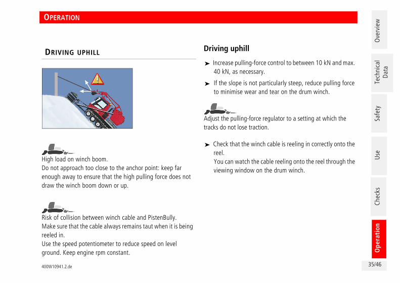
High load on winch boom.Do not approach too close to the anchor point: keep far enough away to ensure that the high pulling force does not draw the winch boom down or up.
Risk of collision between winch cable and PistenBully.Make sure that the cable always remains taut when it is being reeled in. Use the speed potentiometer to reduce speed on level ground. Keep engine rpm constant.
Driving uphill
Increase pulling-force control to between 10 kN and max. 40 kN, as necessary.
If the slope is not particularly steep, reduce pulling force to minimise wear and tear on the drum winch.
Adjust the pulling-force regulator to a setting at which the tracks do not lose traction.
Check that the winch cable is reeling in correctly onto the reel. You can watch the cable reeling onto the reel through the viewing window on the drum winch.
DRIVING UPHILL
11
OPERATION

36/46400W10941.2.de
Situational help
Warning indicator for winch-cable strand monitor 4 lights up:
Cease operation and ascertain the cause of the problem.
Warning indicator for winch cable winding monitor 6 lights up:
Immediately bring the vehicle to a standstill.
Direction of travel switch in neutral position.
Apply the parking brake.
Check the winch cable on the drum.
Pulling force decreases:
Use the potentiometer to reduce driving speed. Keep engine rpm constant.
Relieve the tension on the winch cable before ceasing opera-tions.
Unreel the winch cable as far as the red mark.
Lay the cable on the ground and check for twist.(see customer's workshop information)
Use a low pulling-force setting to reel in the cable and check it for damage.
Resetting acoustic warning for strand monitorIndicator light shows when winch is ON
11
64
RELIEVING TENSION ON THE WINCH CABLE
OPERATION

Ope
rati
onCh
ecks
Use
Safe
tyTe
chni
cal
Data
Ove
rvie
w
400W10941.2.de 37/46
Ope
rati
onCh
ecks
Use
Safe
tyTe
chni
cal
Data
Ove
rvie
w
Drive the PistenBully up as close as possible to the anchor point.
Set the pulling-force regulator to 0.Pulling force is at approximately 10 kN.
Apply the parking brake.
Direction of travel switch in neutral position.
Disengage the load hook from the anchor point.
Risk of damage due to cable unravellingMake sure that the strands of the wire rope cannot untwist.
WARNING!
Risk of accident:- Make sure there is no-one in the danger zone
as the cable is being reeled in.- Do not leave the cockpit.
Reel the cable onto the drum at low pulling force.
Set the pulling-force regulator to 0.
CEASING OPERATION
Set the slewing-gear holding brake to "applied".
– The brake indictor light is ON.
Move the rocker switch to the "unreel" position, overcoming the detent.
P
Set the rocker switch to the "reel in cable" posi-tion.The warning buzzer for slewing-gear holding brake sounds.
OPERATION

38/46400W10941.2.de
Secure the load hook to the winch boom.
The drum winch is in its transport position.
– The indicator light is ON.
Centre the rocker switch.The drum winch is out of action.
Set the rocker switch to the "reel in cable" posi-tion.The warning buzzer for slewing-gear holding brake sounds.
Swivel the winch boom sideways in the direction of travel.
Centre the rocker switch.The drum winch is out of action.
OPERATION

Ope
rati
onCh
ecks
Use
Safe
tyTe
chni
cal
Data
Ove
rvie
w
400W10941.2.de 39/46
Ope
rati
onCh
ecks
Use
Safe
tyTe
chni
cal
Data
Ove
rvie
w
Press the STOP button
if a dangerous situation arises
The PistenBully comes to an immediate stop and will not answer to the steering.
Immediately apply the parking brake.
Set the direction switch to the neutral position.
Switch off the diesel engine.
Check the drum winch and rectify the fault.
A stop places a severe strain on the brakes of the drum winch.
Have the brakes checked for wear and to ensure that they are in full working order.
Driving with the cable attached and the drum winch switched off is prohibited.
Operating the drum winch after a stop
Set the pulling-force regulator to 0.
Turn STOP button 2 and pull it up.
The drum winch is again ready for operation.
2
Centre the rocker switch.The drum winch is out of action.
STOP BUTTON

40/46400W10941.2.de
Tilting the load platform
Risk of PistenBully slipping:Do not tilt the winch unless the vehicle is on level ground.
WARNING!
Make sure there is no-one in the danger zone.
Move the direction of travel switch to the "Neutral" position.
Apply the parking brake.
Start the diesel engine.
Lower the auxiliary equipment, if fitted.
Switch off the diesel engine.
Set the slewing-gear holding brake to "applied".
Centre the rocker switch.The drum winch is out of action.
P
Set the rocker switch to the "reel in cable" position.The warning buzzer for slewing-gear holding brake sounds.
Swivel the winch boom to the rear.
Centre the rocker switch.The drum winch is out of action.
TILTING THE LOAD PLATFORM

Ope
rati
onCh
ecks
Use
Safe
tyTe
chni
cal
Data
Ove
rvie
w
400W10941.2.de 41/46
Ope
rati
onCh
ecks
Use
Safe
tyTe
chni
cal
Data
Ove
rvie
w
Check that screws 1 are secure. Tightening torque MA = 500 Nm.
Remove screws 2.
Tilt the load platform: See the operating manual for the PistenBully.
When the load platform has been returned to its lowered position, tighten screws 2 to the specified tightening torque MA = 500 Nm.
2
2
1
TILTING THE LOAD PLATFORM

42/46400W10941.2.de
Tilting the winch boom
WARNING!
Make sure there is no-one in the danger zone.
Direction of travel switch in neutral position.
Apply the parking brake.
Start the diesel engine.
Lower the equipment carrier.
The winch boom will collide with the driver's cab if it is tilted when swivelled forward.
Switch off the diesel engine.
Set the slewing-gear holding brake to "applied".
Centre the rocker switch.The drum winch is out of action.
– The indicator light is ON.
P
Set the rocker switch to the "reel in cable" posi-tion.The warning buzzer for slewing-gear holding brake sounds.
Swivelling winch boom away from the forward po-sition.
Centre the rocker switch.The drum winch is out of action.
TILTING THE WINCH BOOM

Ope
rati
onCh
ecks
Use
Safe
tyTe
chni
cal
Data
Ove
rvie
w
400W10941.2.de 43/46
Ope
rati
onCh
ecks
Use
Safe
tyTe
chni
cal
Data
Ove
rvie
w
Using manual pump to tilt winch boom:
Pull out keeper 1 and release pin 2.
Turn the manual pump lever to position B.
Fit tube 3 and operate the manual pump.
Using manual pump to raise winch boom:
Turn the manual pump lever to position A.
Fit tube 3 and operate the manual pump.
2
1
AB
3
TILTING THE WINCH BOOM

44/46400W10941.2.de
Removing drum winch
WARNING!
Make sure there is no-one in the danger zone.
Park the PistenBully underneath a crane. Rated lifting capacity of crane min. 2 metric tons and min. 50 cm lift.Comply with all applicable national regulations.
Move the direction of travel switch to the "Neu-tral" position.
Apply the parking brake.
Start the diesel engine.
Lower the auxiliary equipment, if fitted.
Switch off the diesel engine.
Disconnect the hydraulic lines.
Disconnect the electrics.
Install the protective caps.
Set the slewing-gear holding brake to "applied".
Centre the rocker switch.The drum winch is out of action.
P
Centre the rocker switch.The drum winch is out of action.
Set the rocker switch to the "reel in cable" posi-tion.The warning buzzer for slewing-gear holding brake sounds.
Swivelling winch boom to the rear
Centre the rocker switch.The drum winch is out of action.
REMOVING DRUM WINCH

Ope
rati
onCh
ecks
Use
Safe
tyTe
chni
cal
Data
Ove
rvie
w
400W10941.2.de 45/46
Ope
rati
onCh
ecks
Use
Safe
tyTe
chni
cal
Data
Ove
rvie
w
Attach the crane slings to the drum winch.
Remove screws 1 and 2.
Attach the crane slings to the drum winch.
Remove the drum winch.
Tighten screws 1 and 2 in the load platform.
Fit the cover plate onto the upper frame.
Place the winch in storage in the correct manner.
Install the retaining bar.
.
2
2
1
REMOVING DRUM WINCH

46/46400W10941.2.de
Installing drum winchLower the auxiliary equipment, if fitted.
Switch off the diesel engine.
Remove the cover plate from the upper frame.
Remove the retaining bar.
Lower the drum winch onto the guide points on the load platform.
Install screws 1 and 2 and tighten to the specified tight-ening torque MA = 500 Nm.
Disengage the crane slings from the drum winch.
Connect the hydraulic lines.Connect the leak-off oil line first.
Make sure that the hydraulic couplings are secure.
Connect the electric connector.
Direction of travel switch in neutral position.
Apply the parking brake..
Start the diesel engine.
Set the slewing-gear holding brake to "applied".
Centre the rocker switch.The drum winch is out of action.
Set the rocker switch to the "reel in cable" posi-tion.The warning buzzer for slewing-gear holding brake sounds.
Swivel the winch boom sideways in the direction of travel.
Centre the rocker switch.The drum winch is out of action.
P
INSTALLING DRUM WINCH

