operating instructions proline prowirl 72 · 2012-01-31 · operating instructions proline prowirl...
TRANSCRIPT

BA084D/06/en/12.05
71008404
Valid as of software version:
V 1.02.00 (amplifier)
Operating Instructions
Proline Prowirl 72
Vortex Flow Measuring System
4...20 mA HART
6

Brief operating instructions Proline Prowirl 72
2 Endress+Hauser
Brief operating instructions
These brief operating instructions explain how to commission your measuring device quickly and
easily:
Safety instructions Page 7
Æ
Installation Page 11
Æ
Wiring Page 21
Æ
Display and operating elements Page 27
Æ
Commissioning with “QUICK SETUP” Page 40
You can commission your measuring device quickly and easily using the special “Quick
Setup” menu. It allows you to configure important basic functions via the local display, for
example display language, measured variables, engineering units, signal type etc.
Æ
Customer-specific configuration /
Description of device functions
Page 71 ff.
Complex measurement tasks require the configuration of additional functions which you
can individually select, set and adapt to your process conditions using the function matrix.
The function matrix of the measuring device and all the functions are described in detail in
the “Description of device functions” section.

Proline Prowirl 72 QUICK SETUP for quick commissioning
Endress+Hauser 3
QUICK SETUP for quick commissioning
A0003394-EN
! Note!
The display returns to the QUICK SETUP COMMISSIONING cell if you press the ESC key combination X during
interrogation.
m Only the output (current output or pulse/status output) not yet configured in the current Quick Setup is offered for
selection after the first cycle.
n The “YES” option appears as long as a free output is still available. “NO” is the only option displayed when no
further outputs are available.
o When “YES” is selected, the flow is assigned to line 1 of the local display and the totalizer to line 2.
++ +E E
n
m
o
Esc
E+-
XXX.XXX.XX
Yes
Yes
No
No
Measuring Unit Type
Configuration another output ?
Automatically configuration display ?
Automaticallyparameterization
of the display
Language
Application
Quick SetupQuick SetupCommission
Corrected Volume FlowVolume Flow Calculated Mass Flow
QuitCurrentoutput
Pulse /Status output
Selection output type
UnitFlow
UnitFlow
UnitTotalizer
UnitFlow
UnitTotalizer
UnitTotalizer
UnitDensity
UnitDensity
OperatingDensity
OperatingDensity
ReferenceDensity
OperationMode
Pulse Status
Assignstatus
Pulsevalue
Currentspan
Onvalue
Pulsewidth
Value20 mA
Offvalue
Outputsignal
Timeconstant
Timeconstant
Failsafemode
Failsafemode
Vortex Freq. PFM
HOME-POSITION

QUICK SETUP for quick commissioning Proline Prowirl 72
4 Endress+Hauser

Proline Prowirl 72 Table of Contents
Endress+Hauser 5
Table of Contents
Brief operating instructions . . . . . . . . . . . . . 2
QUICK SETUP for quick commissioning . . . 3
Table of Contents . . . . . . . . . . . . . . . . . . . . . 5
1 Safety instructions . . . . . . . . . . . . . . . . . . . . . 7
1.1 Designated use . . . . . . . . . . . . . . . . . . . . . . . . . . . . 7
1.2 Installation, commissioning and operation . . . . . . . . 7
1.3 Operational safety . . . . . . . . . . . . . . . . . . . . . . . . . . 7
1.4 Return . . . . . . . . . . . . . . . . . . . . . . . . . . . . . . . . . . . 8
1.5 Notes on safety conventions and icons . . . . . . . . . . . 8
2 Identification . . . . . . . . . . . . . . . . . . . . . . . . . . 9
2.1 Device designation . . . . . . . . . . . . . . . . . . . . . . . . . 9
2.1.1 Nameplate on the transmitter . . . . . . . . . . . 9
2.1.2 Sensor nameplate (remote version) . . . . . . 10
2.2 Certificates and approvals . . . . . . . . . . . . . . . . . . . 10
2.3 Registered trademarks . . . . . . . . . . . . . . . . . . . . . . 10
3 Installation . . . . . . . . . . . . . . . . . . . . . . . . . . 11
3.1 Incoming acceptance, transport, storage . . . . . . . . . 11
3.1.1 Incoming acceptance . . . . . . . . . . . . . . . . . 11
3.1.2 Transport . . . . . . . . . . . . . . . . . . . . . . . . . 11
3.1.3 Storage . . . . . . . . . . . . . . . . . . . . . . . . . . . 11
3.2 Installation conditions . . . . . . . . . . . . . . . . . . . . . . 12
3.2.1 Dimensions . . . . . . . . . . . . . . . . . . . . . . . . 12
3.2.2 Installation location . . . . . . . . . . . . . . . . . . 12
3.2.3 Orientation . . . . . . . . . . . . . . . . . . . . . . . . 12
3.2.4 Heat insulation . . . . . . . . . . . . . . . . . . . . . 13
3.2.5 Inlet and outlet run . . . . . . . . . . . . . . . . . . 14
3.2.6 Vibrations . . . . . . . . . . . . . . . . . . . . . . . . . 15
3.2.7 Limiting flow . . . . . . . . . . . . . . . . . . . . . . . 15
3.3 Installation . . . . . . . . . . . . . . . . . . . . . . . . . . . . . . 16
3.3.1 Mounting the sensor . . . . . . . . . . . . . . . . . 16
3.3.2 Rotating the transmitter housing . . . . . . . . 17
3.3.3 Rotating the local display . . . . . . . . . . . . . . 17
3.3.4 Mounting the transmitter (remote version) . 18
3.4 Post-installation check . . . . . . . . . . . . . . . . . . . . . . 19
4 Wiring . . . . . . . . . . . . . . . . . . . . . . . . . . . . . . . 21
4.1 Connecting the remote version . . . . . . . . . . . . . . . 21
4.1.1 Connecting the sensor . . . . . . . . . . . . . . . . 21
4.1.2 Cable specifications . . . . . . . . . . . . . . . . . . 22
4.2 Connecting the measuring unit . . . . . . . . . . . . . . . 22
4.2.1 Connecting the transmitter . . . . . . . . . . . . 22
4.2.2 Terminal assignment . . . . . . . . . . . . . . . . . 24
4.2.3 HART connection. . . . . . . . . . . . . . . . . . . . 25
4.3 Degree of protection . . . . . . . . . . . . . . . . . . . . . . . 26
4.4 Post-connection check . . . . . . . . . . . . . . . . . . . . . . 26
5 Operation . . . . . . . . . . . . . . . . . . . . . . . . . . . . 27
5.1 Display and operating elements . . . . . . . . . . . . . . . 27
5.2 The function matrix: layout and use . . . . . . . . . . . . 28
5.2.1 General notes . . . . . . . . . . . . . . . . . . . . . . . 29
5.2.2 Enabling the programming mode . . . . . . . . 29
5.2.3 Disabling the programming mode . . . . . . . . 29
5.3 Error message display . . . . . . . . . . . . . . . . . . . . . . . 30
5.4 Communication (HART) . . . . . . . . . . . . . . . . . . . . 31
5.4.1 Operating options . . . . . . . . . . . . . . . . . . . 31
5.4.2 Device variables and process variables . . . . 32
5.4.3 Universal / common practice
HART commands . . . . . . . . . . . . . . . . . . . 32
5.4.4 Device status / error messages . . . . . . . . . . 37
5.4.5 Switching HART write protection on/off . . . 38
6 Commissioning . . . . . . . . . . . . . . . . . . . . . . 39
6.1 Function check . . . . . . . . . . . . . . . . . . . . . . . . . . . 39
6.2 Commissioning . . . . . . . . . . . . . . . . . . . . . . . . . . . 39
6.2.1 Switching on the measuring device . . . . . . 39
6.2.2 “Commissioning” Quick Setup . . . . . . . . . . 40
7 Maintenance . . . . . . . . . . . . . . . . . . . . . . . . . 43
8 Accessories . . . . . . . . . . . . . . . . . . . . . . . . . . 45
9 Trouble-shooting . . . . . . . . . . . . . . . . . . . . . 47
9.1 Trouble-shooting instructions . . . . . . . . . . . . . . . . . 47
9.2 System error messages . . . . . . . . . . . . . . . . . . . . . . 48
9.3 Process errors without messages . . . . . . . . . . . . . . 50
9.4 Response of outputs to errors . . . . . . . . . . . . . . . . . 52
9.5 Spare parts . . . . . . . . . . . . . . . . . . . . . . . . . . . . . . . 53
9.6 Installing and removing electronics boards . . . . . . . 54
9.6.1 Non-Ex / Ex-i and Ex n version . . . . . . . . . 54
9.6.2 Ex d version . . . . . . . . . . . . . . . . . . . . . . . . 56
9.7 Software history . . . . . . . . . . . . . . . . . . . . . . . . . . . 58
10 Technical data . . . . . . . . . . . . . . . . . . . . . . . 59
10.1 Technical data at a glance . . . . . . . . . . . . . . . . . . . 59
10.1.1 Application . . . . . . . . . . . . . . . . . . . . . . . . 59
10.1.2 Function and system design . . . . . . . . . . . . 59
10.1.3 Input . . . . . . . . . . . . . . . . . . . . . . . . . . . . . 59
10.1.4 Output . . . . . . . . . . . . . . . . . . . . . . . . . . . 60
10.1.5 Power supply . . . . . . . . . . . . . . . . . . . . . . . 61
10.1.6 Performance characteristics . . . . . . . . . . . . 62
10.1.7 Operating conditions: installation . . . . . . . . 62
10.1.8 Operating conditions: environment . . . . . . . 63
10.1.9 Operating conditions: process . . . . . . . . . . . 63
10.1.10Frequency ranges for air and water . . . . . . . 66
10.1.11Mechanical construction . . . . . . . . . . . . . . 66
10.1.12Human interface . . . . . . . . . . . . . . . . . . . . 67
10.1.13Certificates and approvals . . . . . . . . . . . . . . 68
10.1.14Accessories . . . . . . . . . . . . . . . . . . . . . . . . 68

Table of Contents Proline Prowirl 72
6 Endress+Hauser
10.1.15Documentation . . . . . . . . . . . . . . . . . . . . 68
10.2 Dimensions of flow conditioner
according to EN (DIN) / ANSI / JIS . . . . . . . . . . . 69
11 Description of device functions . . . . . . . 71
11.1 Illustration of the function matrix . . . . . . . . . . . . . 71
11.2 Description of functions . . . . . . . . . . . . . . . . . . . . 72
11.2.1 Group MEASURED VALUES . . . . . . . . . . 72
11.2.2 Group SYSTEM UNITS . . . . . . . . . . . . . . . 73
11.2.3 Group QUICK SETUP . . . . . . . . . . . . . . . . 77
11.2.4 Group OPERATION . . . . . . . . . . . . . . . . . 78
11.2.5 Group USER INTERFACE . . . . . . . . . . . . . 80
11.2.6 Group TOTALIZER . . . . . . . . . . . . . . . . . . 82
11.2.7 Group CURRENT OUTPUT . . . . . . . . . . . 84
11.2.8 Group PULSE/STATUS OUTPUT . . . . . . . 86
11.2.9 Information on the response of
the status output . . . . . . . . . . . . . . . . . . . 93
11.2.10Group COMMUNICATION . . . . . . . . . . . 94
11.2.11Group PROCESS PARAMETER . . . . . . . . . 95
11.2.12Group SYSTEM PARAMETER . . . . . . . . . 99
11.2.13Group SENSOR DATA . . . . . . . . . . . . . . 100
11.2.14Group SUPERVISION . . . . . . . . . . . . . . . 102
11.2.15Group SIMULATION SYSTEM . . . . . . . 103
11.2.16Group SENSOR VERSION . . . . . . . . . . . 104
11.2.17Group AMPLIFIER VERSION . . . . . . . . 104
12 Factory settings . . . . . . . . . . . . . . . . . . . . 105
12.1 Metric system units (not for USA and Canada) . . 105
12.2 US units (only for USA and Canada) . . . . . . . . . . 107
12.3 Meter body type MB (meter body) . . . . . . . . . . . 108
Index of key words . . . . . . . . . . . . . . . . . 109

Proline Prowirl 72 1 Safety instructions
Endress + Hauser 7
1 Safety instructions
1.1 Designated use
The measuring system is used to measure the volume flow of saturated steam, over-heated steam,
gases and liquids. If the process pressure and process temperature are constant, the measuring
device can also output the flow as the calculated mass flow and corrected volume flow.
Resulting from incorrect use or from use other than that designated the operational safety of the
measuring devices can be suspended. The manufacturer accepts no liability for damages being
produced from this.
1.2 Installation, commissioning and operation
Note the following points:
• Installation, electrical installation, commissioning and maintenance of the device must be carried
out by trained, qualified specialists authorized to perform such work by the facility's owner-
operator. The specialist must have read and understood these Operating Instructions and must
follow the instructions they contain.
• The device must be operated by persons authorized and trained by the facility's owner-operator.
Strict compliance with the instructions in these Operating Instructions is mandatory.
• In the case of special fluids (incl. fluids for cleaning), Endress+Hauser will be happy to assist in
clarifying the material resistance properties of wetted parts. However, the user is responsible for
the choice of wetted materials as regards their in-process resistance to corrosion. The
manufacturer refuses to accept liability.
• The installer must ensure that the measuring system is correctly wired in accordance with the
wiring diagrams.
• Invariably, local regulations governing the opening and repair of electrical devices apply.
1.3 Operational safety
Note the following points:
• Measuring systems for use in hazardous environments are accompanied by separate “Ex
documentation”, which is an integral part of these Operating Instructions. Strict compliance with
the installation instructions and ratings as listed in this supplementary documentation is
mandatory.
The symbol on the front of the Ex documentation indicates the approval and the certification
center (0 Europe, 2 USA, 1 Canada).
• The measuring system complies with the general safety requirements in accordance with
EN 61010 and the EMC requirements of EN 61326/A1 and NAMUR Recommendations NE 21
and NE 43.
• The manufacturer reserves the right to modify technical data without prior notice. Your
Endress+Hauser distributor will supply you with current information and updates to these
Operating Instructions.

1 Safety instructions Proline Prowirl 72
8 Endress + Hauser
1.4 Return
The following procedures must be carried out before a flowmeter requiring repair or calibration, for
example, is returned to Endress+Hauser:
• Always enclose a fully completed “Declaration of Contamination” form with the device. Only
then can Endress+Hauser transport, examine and repair a returned device.
! Note!
A copy of the “Declaration of Contamination” can be found at the end of these Operating
Instructions.
• Enclose special handling instructions if necessary, for example a safety data sheet as per European
Directive 91/155/EEC.
• Remove all fluid residues. Pay special attention to the grooves for seals and crevices which could
contain fluid residues.
This is particularly important if the fluid is hazardous to health, e.g. flammable, toxic, caustic,
carcinogenic, etc.
# Warning!
• Do not return a measuring device if you are not absolutely certain that all traces of hazardous
substances have been removed, e.g. substances which have penetrated crevices or diffused
through plastic.
• Costs incurred for waste disposal and injury (caustic burns, etc.) due to inadequate cleaning will
be charged to the owner-operator.
1.5 Notes on safety conventions and icons
The devices are designed to meet state-of-the-art safety requirements, have been tested and left the
factory in a condition in which they are safe to operate.
The devices comply with the applicable standards and regulations in accordance with EN 61010
“Protection Measures for Electrical Equipment for Measurement, Control, Regulation and
Laboratory Procedures”. They can, however, be a source of danger if used incorrectly or for
anything other than the designated use.
Consequently, always pay particular attention to the safety instructions indicated in these Operating
Instructions by the following symbols:
# Warning!
“Warning” indicates an action or procedure which, if not performed correctly, can result in injury
or a safety hazard. Comply strictly with the instructions and proceed with care.
" Caution!
“Caution” indicates an action or procedure which, if not performed correctly, can result in incorrect
operation or destruction of the device. Comply strictly with the instructions.
! Note!
“Note” indicates an action or procedure which, if not performed correctly, can have an indirect
effect on operation or trigger an unexpected response on the part of the device.

Proline Prowirl 72 2 Identification
Endress + Hauser 9
2 Identification
2.1 Device designation
The “Proline Prowirl 72” flowmeter system consists of the following components:
• Transmitter Proline Prowirl 72
• Prowirl F or Prowirl W sensor
In the compact version, the transmitter and sensor form a mechanical unit; in the remote version
they are mounted separate from one another.
2.1.1 Nameplate on the transmitter
A0003585
Fig. 1: Nameplate specifications for transmitter and sensor (example)
A = nameplate on transmitter, B = nameplate on transmitter (only compact version)
1 Order code / serial number: see the specifications on the order confirmation for the meanings of the individual
letters and digits.
2 Power supply / frequency: 12...36 V DC, Power consumption: 1.2 W
3 Available outputs: Current output 4...20 mA
4 Data regarding Pressure Equipment Directive (optional)
5 Calibration factor
6 Material sensor and gasket
7 Medium temperature range
8 Reserved for information on special products
9 Permitted ambient temperature range
10 Degree of protection
PROWIRL 72
ABCDEFGHJKLMNPQRSTTAG No.:
Ser.No.: 12345678901
Order Code:
i
IP67 / NEMA/Type4X
-40°F<Ta<+158°FTa+10°C/18°F
72XXX-XXXXXXXXXXX
12-36VDC
3.1
K-factor:
Gasket:TM:
Materials: CF3M/F316/F316L/1.4404Graphite-200°C...+400°C/-328°F...+752°F
1.0000 P/L
Sensor data:
Pat. US 4,743,837 US 6,003,384
Ser.No.: 12345678901PROWIRL W
pnom = PS= 10bar / p test = 20bar
4...20mA, HART
Pat. EP 841 545 EP 226 082Pat. US 4,743,837 US 6,003,384
1.2W
-40°C<Ta<+70°C
PED 97/23/EC: Cat. III
A
B
1
4
5
7
9
101
23
4
6
8
Meter Body MB: 25

2 Identification Proline Prowirl 72
10 Endress + Hauser
2.1.2 Sensor nameplate (remote version)
A0003584
Fig. 2: Nameplate specifications for transmitter remote version “Proline Prowirl 72” (example)
1 Order code / serial number: see the specifications on the order confirmation for the meanings of the individual
letters and digits.
2 Calibration factor
3 Material sensor
4 Material gasket
5 Medium temperature range
6 Reserved for information on special products
7 Permitted ambient temperature range
8 Degree of protection
2.2 Certificates and approvals
The devices are designed to meet state-of-the-art safety requirements in accordance with sound
engineering practice. They have been tested and left the factory in a condition in which they are
safe to operate. The devices comply with the applicable standards and regulations in accordance
with EN 61010 “Protection Measures for Electrical Equipment for Measurement, Control,
Regulation and Laboratory Procedures” and the EMC requirements as per EN 61326/A1.
The measuring system described in these Operating Instructions is therefore in conformity with the
statutory requirements of the EC Directives. Endress+Hauser confirms successful testing of the
device by affixing to it the CE mark.
The measuring system is in conformity with the EMC requirements of the Australian
Communications Authority (ACA).
2.3 Registered trademarks
GYLON ®
Registered trademark of Garlock Sealing Technologies, Palmyar, NY, USA
HART ®
Registered trademark of the HART Communication Foundation, Austin, USA
INCONEL ®
Registered trademark of Inco Alloys International Inc., Huntington, USA
KALREZ ®, VITON ®
Registered trademark of E.I. Du Pont de Nemours & Co., Wilmington, USA
ToF Tool - Fieldtool® Package, Fieldcheck®, Applicator®
Registered or registration-pending trademarks of Endress+Hauser Flowtec AG, Reinach,
Switzerland
ABCDEFGHJKLMNPQRSTTAG No.:Ser.No.: 12345678901Order Code:
Pat. US 4,743,837 US 6,003,384
i
IP67/NEMA/Type 4X
-40°C<Ta<+85°C-40°F<Ta<+185°F
Gasket:
TM:
Graphite-200°C...+400°C/-328°F...+752°F
72WXX-XXXXXXXXXXXX
K-factor: 1.0000 P/L
Materials: CF3M/F316/F316L/1.4404
PROWIRL W
3.1
1
56
7
8
234
Meter Body MB: 25

Proline Prowirl 72 3 Installation
Endress + Hauser 11
3 Installation
3.1 Incoming acceptance, transport, storage
3.1.1 Incoming acceptance
On receipt of the goods, check the following points:
• Check the packaging and the contents for damage.
• Check the shipment, make sure nothing is missing and that the scope of supply matches your
order.
3.1.2 Transport
Please note the following when unpacking or transporting to the measuring point:
• The devices must be transported in the container supplied.
• Devices with nominal diameter DN 40...300 may not be lifted at the transmitter housing or at the
connection housing of the remote version when transporting (see Fig. 3). Use carrier slings when
transporting and put the slings around both process connections. Avoid chains as these could
damage the housing.
# Warning!
Risk of injury if the measuring device slips.
The center of gravity of the entire measuring device might be higher than the points around which
the slings are slung. Therefore, when transporting, make sure that the device does not
unintentionally turn or slip.
A0001871
Fig. 3: Instructions for transporting sensors with DN 40...300
3.1.3 Storage
Note the following points:
• Pack the measuring device in such a way as to protect it reliably against impact for storage (and
transportation). The original packaging provides optimum protection.
• The permissible storage temperature is –40...+80 °C
(ATEX II 1/2 GD version/dust ignition-proof –20...+55 °C).
• When in storage, the device should not be exposed to direct sunlight in order to avoid
impermissibly high surface temperatures.

3 Installation Proline Prowirl 72
12 Endress + Hauser
3.2 Installation conditions
Note the following points:
• The measuring device requires a fully developed flow profile as a prerequisite for correct volume
flow measurement. The inlet and outlet runs must be taken into account (see Page 14).
• The maximum permitted ambient temperatures (see Page 63) and fluid temperatures
(see Page 63) must be observed.
• Pay particular attention to the notes on orientation and piping insulation (see Page 12).
• Verify that the correct nominal diameter and pipe standard (DIN/JIS/ANSI) were taken into
account when ordering since the calibration of the device and the achievable accuracy depend on
these factors. If the mating pipe and the device have different nominal diameters/pipe standards,
an inlet correction can be made via the device software by entering the actual pipe diameter (see
MATING PIPE DIAMETER function on Page 97).
• The correct operation of the measuring system is not influenced by plant vibrations up to 1 g,
10...500 Hz.
• For mechanical reasons, and in order to protect the piping, it is advisable to support heavy sensors.
For weight information, please refer to Technical Information TI070D/06/en.
3.2.1 Dimensions
The dimensions and lengths of the sensor and transmitter can be found in the Technical Information
TI070D/06/en.
3.2.2 Installation location
We recommend you observe the following dimensions to guarantee problem-free access to the
device for service purposes:
• Minimum spacing in all directions = 100 mm
• Necessary cable length: L + 150 mm
A0001870
Fig. 4: A = Minimum spacing in all directions, L = cable length
3.2.3 Orientation
The device can generally be installed in any position in the piping.
In the case of liquids, there should be upward flow in vertical pipes to avoid partial pipe filling (see
orientation A).
In the case of hot fluids (e.g. steam or fluid temperature ≥ 200 °C), select orientation C or D so that
the permitted ambient temperature of the electronics is not exceeded. Orientations B and D are
recommended for very cold fluids (e.g. liquid nitrogen) (see Page 13).
L
A

Proline Prowirl 72 3 Installation
Endress + Hauser 13
Orientations B, C and D are possible with horizontal installation (see Page 13).
The arrow indicated on the device must always point in the direction of flow in all orientations.
" Caution!
• If fluid temperature is ≥ 200 °C, orientation B is not permitted for the wafer version
(Prowirl 72 W) with a nominal diameter of DN 100 and DN 150.
• In case of vertical orientation and downward flowing liquid, the piping has always to be
completely filled.
A0001869
Fig. 5: Possible orientations of the device
3.2.4 Heat insulation
Some fluids require suitable measures to avoid heat transfer at the sensor. A wide range of materials
can be used to provide the required insulation.
When insulating, please ensure that a sufficiently large area of the housing support is exposed. The
uncovered part serves as a radiator and protects the electronics from overheating (or undercooling).
The maximum insulation height permitted is illustrated in the diagrams. These apply equally to both
the compact version and the sensor in the remote version.
A0001868
Fig. 6: 1 = Flanged version, 2 = Wafer version
" Caution!
Danger of electronics overheating!
• Therefore, make sure that the adapter between sensor and transmitter and the connection
housing of the remote version is always exposed.
• Note that a certain orientation might be required, depending on the fluid temperature → Page 12.
• Information on permissible temperature ranges → Page 63.
B
D
A
C
1 2Esc
E- +Esc
E- +

3 Installation Proline Prowirl 72
14 Endress + Hauser
3.2.5 Inlet and outlet run
As a minimum, the inlet and outlet runs shown below must be observed to achieve the specified
accuracy of the device. The longest inlet run shown must be observed if two or more flow
disturbances are present.
A0001867
Fig. 7: Minimum inlet and outlet runs with various flow obstructions
A Inlet run
B Outlet run
1 = Reduction
2 = Expansion
3 = 90 ° elbow or T-piece
4 = 2 x 90 ° elbow, 3-dimensional
5 = 2 x 90 ° elbow
6 = Control valve
! Note!
A specially designed perforated plate flow conditioner can be installed if it is not possible to observe
the inlet runs required (see Page 15).
Esc
E- +
Esc
E- +Esc
E- +
Esc
E- +
15 x DN 5 x DN
A
1
3
5
2
4
6
A
A
A
A
A
B
B
B
B
B
B
18 x DN 5 x DN
20 x DN 5 x DN 40 x DN 5 x DN
25 x DN 5 x DN 50 x DN 5 x DN
Esc
E- +Esc
E- +

Proline Prowirl 72 3 Installation
Endress + Hauser 15
Outlet runs with pressure and temperature measuring points
If pressure and temperature measuring points are installed after the device, please ensure there is a
large enough distance between the device and the measuring point so there are no negative effects
on vortex formation in the sensor.
A0003780
Fig. 8: Installation of pressure measuring point (PT) and temperature measuring point (TT)
Perforated plate flow conditioner
A specially designed perforated plate flow conditioner, available from Endress+Hauser, can be
installed if it is not possible to observe the inlet runs required. The flow conditioner is fitted between
two piping flanges and centered with mounting bolts. Generally, this reduces the inlet run required
to 10 x DN with complete accuracy.
A0001887
Fig. 9: Perforated plate flow conditioner
Examples of pressure loss for flow conditioner
The pressure loss for flow conditioners is calculated as follows:
∆p [mbar] = 0.0085 · ρ [kg/m³] · v² [m/s]
3.2.6 Vibrations
The correct operation of the measuring system is not influenced by plant vibrations up to 1 g,
10...500 Hz. Consequently, the sensors require no special measures for attachment.
3.2.7 Limiting flow
See the information on Page 59 and 65.
• Example with steam
p = 10 bar abs
t = 240 °C → ρ = 4.39 kg/m³
v = 40 m/s
∆p = 0.0085 · 4.39 · 40² = 59.7 mbar
• Example with H2O condensate (80 °C)
ρ = 965 kg/m³
v = 2.5 m/s
∆p = 0.0085 · 965 · 2.5² = 51.3 mbar
PT TT
3...5 x DN
4...8 x DN
Esc
E- +
8 x DN2 x DN 5 x DN

3 Installation Proline Prowirl 72
16 Endress + Hauser
3.3 Installation
3.3.1 Mounting the sensor
" Caution!
Please note the following prior to mounting:
• Prior to installing the measuring device in the piping, remove all traces of transport packaging and
any protective covers from the sensor.
• Make sure that the internal diameters of seals are the same as, or greater than, those of the
measuring pipe and piping. Seals projecting into the flow current have a negative effect on the
vortex formation after the bluff body and cause inaccurate measurement. For this reason, the seals
supplied by Endress+Hauser for the wafer version have a slightly larger internal diameter than the
measuring pipe.
• Ensure that the arrow on the measuring pipe matches the direction of flow in the piping.
• Lengths:
– Prowirl W (wafer version): 65 mm
– Prowirl F (flanged version) → See Technical Information TI070D/06/en.
Mounting Prowirl W
The centering rings supplied are used to mount and center the wafer-style devices.
A mounting kit consisting of tie rods, seals, nuts and washers can be ordered separately.
A0001888
Fig. 10: Mounting the wafer version
1 Nut
2 Washer
3 Tie rod
4 Centering ring (is supplied with the device)
5 Seal
1
2
3
4
5

Proline Prowirl 72 3 Installation
Endress + Hauser 17
3.3.2 Rotating the transmitter housing
The electronics housing can be rotated continuously 360 ° on the housing support.
1. Loosen the safety screw.
2. Turn the transmitter housing to the desired position (max. 180 ° in each direction to the stop).
Note!
There are recesses in the rotating groove at 90 ° stages (only compact version).
These help you align the transmitter easier.
3. Tighten the safety screw.
A0001889
Fig. 11: Rotating the transmitter housing
3.3.3 Rotating the local display
1. Unscrew the cover of the electronics compartment from the transmitter housing.
2. Remove the display module from the transmitter retainer rails.
3. Turn the display to the desired position (max. 4 x 45 ° in each direction) and reset it onto the
retaining rails.
4. Screw the cover of the electronics compartment firmly back onto the transmitter housing.
A0003237
Fig. 12: Rotating the local display
180°
180°
4 x 45°

3 Installation Proline Prowirl 72
18 Endress + Hauser
3.3.4 Mounting the transmitter (remote version)
The transmitter can be mounted in the following ways:
• Wall mounting
• Pipe mounting (with separate mounting kit, accessories see Page 45)
The transmitter and the sensor must be mounted separate in the following circumstances:
• Poor accessibility
• Lack of space
• Extreme ambient temperatures
" Caution!
If the device is mounted to warm piping, make certain that the housing temperature does not
exceed the max. permissible value of +80 °C.
Mount the transmitter as illustrated in the diagram.
A0003801
Fig. 13: Mounting the transmitter (remote version)
A Direct wall mounting
B Pipe mounting
* Dimensions for version without local operation
ANSCHLUSSKLEMMEN - FIELD TERMINALS
232 (*226)
227 (*221)
ANSCHLUSSKLEMMEN - FIELD TERMINALS
A
B
EscEsc
E- +
EscEsc
E- +
EscEsc
E- +

Proline Prowirl 72 3 Installation
Endress + Hauser 19
3.4 Post-installation check
Perform the following checks after installing the measuring device in the piping:
Device condition and specifications Notes
Is the device damaged (visual inspection)? −
Do the process temperature/pressure, ambient temperature, measuring range
etc. correspond to the specifications of the device?
see Page 59 ff.
Installation Notes
Does the arrow on the pipe stand or on the sensor match the direction of flow
through the pipe?
−
Are the measuring point number and labeling correct (visual inspection)? –
Is the orientation chosen for the sensor correct, in other words suitable for
sensor type, fluid properties (outgassing, with entrained solids) and fluid
temperature?
see Page 12 ff.
Process environment / process conditions Notes
Is the measuring device protected against moisture and direct sunlight? −

3 Installation Proline Prowirl 72
20 Endress + Hauser
Proline Prowirl 72 4 Wiring
Endress + Hauser 21
4 Wiring
# Warning!
When connecting Ex-certified devices, please refer to the notes and diagrams in the Ex-specific
supplement to these Operating Instructions.
Please do not hesitate to contact your Endress+Hauser representative if you have any questions.
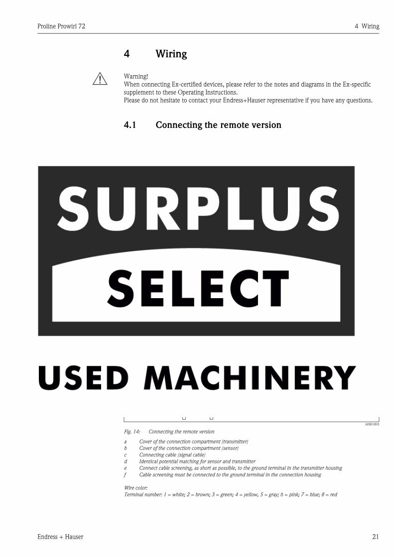
4.1 Connecting the remote version
4.1.1 Connecting the sensor
! Note!
• The remote version must be grounded. In doing so, the sensor and transmitter must be connected
to the same potential matching.
• When using the remote version, always make sure that you connect the sensor only to the
transmitter with the same serial number. Compatibility errors (e.g. the incorrect K-factor will be
used) can occur if the devices are not connected in this way.
1. Remove the cover of the connection compartment of the transmitter (a).
2. Remove the cover of the connection compartment of the sensor (b).
3. Feed the connecting cable (c) through the appropriate cable entries.
4. Wire the connecting cable between the sensor and transmitter in accordance with the
electrical connection diagram:
→ Fig. 14
→ Wiring diagram in the screw caps
5. Tighten the glands of the cable entries on the sensor housing and transmitter housing.
6. Screw the cover of the connection compartment (a/b) back onto the sensor housing or
transmitter housing.
A0001893
Fig. 14: Connecting the remote version
a Cover of the connection compartment (transmitter)
b Cover of the connection compartment (sensor)
c Connecting cable (signal cable)
d Identical potential matching for sensor and transmitter
e Connect cable screening, as short as possible, to the ground terminal in the transmitter housing
f Cable screening must be connected to the ground terminal in the connection housing
Wire color:
Terminal number: 1 = white; 2 = brown; 3 = green; 4 = yellow, 5 = gray; 6 = pink; 7 = blue; 8 = red
a
cb
d
3
3
1
1
4
4
2
2
5
5
6
6
7
7
8
8
DIF
F+
DIF
F+
DIF
F–
DIF
F–
GR
OU
ND
GR
OU
ND
+5
VA
+5
VA
–5
VA
–5
VA
TE
MP
1T
EM
P1
TE
MP
2T
EM
P2
TE
MP
3T
EM
P3
e
f

4 Wiring Proline Prowirl 72
22 Endress + Hauser
4.1.2 Cable specifications
The specifications of the cable connecting the transmitter and the sensor of the remote version are
as follows:
• 4 x 2 x 0.5 mm2 PVC cable with common shield (4 pairs, pair-stranded).
• Cable length: max. 30 m
• Conductor resistance according to DIN VDE 0295 class 5 or IEC 60228 class 5
• Capacity core/screen: < 400 pF/m
• Operating temperature: –40...+105 °C
4.2 Connecting the measuring unit
4.2.1 Connecting the transmitter
! Note!
• When connecting Ex-certified devices, please refer to the notes and diagrams in the Ex-specific
supplement to these Operating Instructions.
• The remote version must be grounded. In doing so, the sensor and transmitter must be connected
to the same potential matching.
• The national regulations governing the installation of electrical equipment must be observed.
• When connecting the transmitter, use a connecting cable with a continuous service temperature
of at least –40 °C... (permitted max. ambient temperature plus 10 °C).
Procedure for connecting the transmitter, Non-Ex / Ex i and Ex n version (→ Fig. 15)
1. Unscrew the cover (a) of the electronics compartment from the transmitter housing.
2. Remove the display module (b) from the retaining rails (c) and refit onto right retaining rail with
the left side (this secures the display module).
3. Loosen screw (d) of the cover of the connection compartment and fold down the cover.
4. Push the cable for the power supply/current output through the cable gland (e).
Optional: push the cable for the pulse output through the cable gland (f).
5. Tighten the cable glands (e / f) (see also → Page 26).
6. Pull the terminal connector (g) out of the transmitter housing and connect the cable for the
power supply/current output (see → Fig. 17).
Optional: Pull terminal connector (h) out of the transmitter housing and connect the cable
for the pulse output (see → Fig. 17).
! Note!
The terminal connectors (g / h) are pluggable, i.e. they can be plugged out of the transmitter
housing to connect the cables.
7. Plug the terminal connectors (g / h) into the transmitter housing.
! Note!
The connectors are coded so you cannot mix them up.

Proline Prowirl 72 4 Wiring
Endress + Hauser 23
8. Only remote version: Secure the ground cable to the ground terminal (i).
9. Fold up the cover of the connection compartment and tighten the screws (d).
10. Remove the display module (b) and fit on the retaining rails (c).
Screw the cover of the electronics compartment (a) onto the transmitter housing.
A0001895
Fig. 15: Procedure for connecting the transmitter Non-Ex / Ex i and Ex n version
a Cover of electronics compartment
b Retaining rail for display module
c Display module
d Connection compartment cover threaded connection
e Cable gland for power supply/current output cable
f Cable gland for pulse output cable (optional)
g Terminal connector for power supply/current output
h Terminal connector for pulse output (optional)
Procedure for connecting the transmitter, Ex d version (→ Fig. 16)
! Note!
When connecting Ex-certified devices, please refer to the notes and diagrams in the Ex-specific
supplement to these Operating Instructions.
1. Open the clamp (a) securing the cover of the connection compartment.
2. Unscrew the cover (b) of the connection compartment from the transmitter housing.
3. Push the cable for the power supply/current output through the cable gland (c).
Optional: push the cable for the pulse output through the cable gland (d).
4. Tighten the cable glands (c / d) (see also → Page 26).
5. Pull the terminal connector (e) out of the transmitter housing and connect the cable for the
power supply/current output (see → Fig. 17).
Optional: Pull terminal connector (f) out of the transmitter housing and connect the cable for
the pulse output (see → Fig. 17).
! Note!
The terminal connectors (e / f) are pluggable, i.e. they can be plugged out of the transmitter
housing to connect the cables.
e
f
g h
da
c
b
d

4 Wiring Proline Prowirl 72
24 Endress + Hauser
6. Plug the terminal connectors (e / f) into the transmitter housing.
! Note!
The connectors are coded so you cannot mix them up.
7. Only remote version: Secure the ground cable to the ground terminal (Fig. 17, c).
8. Screw the cover (b) of the connection compartment onto the transmitter housing.
9. Tighten the clamp (a) securing the cover of the connection compartment.
A0001896
Fig. 16: Procedure for connecting the transmitter Ex d version
a Clamp securing the cover of the connection compartment
b Cover of connection compartment
c Cable gland for power supply/current output cable
d Cable gland for pulse output cable (optional)
e Terminal connector for power supply/current output
f Terminal connector for pulse output (optional)
Wiring diagram
A0003392
Fig. 17: Assignment of terminals
A Power supply/current output
B Optional pulse output/status output
C Ground terminal (only relevant for remote version)
D PFM wiring (pulse-frequency modulation)
4.2.2 Terminal assignment
Terminal no. (inputs/outputs)
Order variant 1 − 2 3 − 4
72***-***********W HART current output −
72***-***********A HART current output Pulse/status output
HART current output
Galvanically isolated, 4...20 mA with HART
Pulse/status output
Open collector, passive, galvanically isolated, Umax = 30 V, with 15 mA current limiting, Ri = 500 Ω,
can be configured as pulse or status output
fe
ba
cd
1 2 1 23 4 3 4
A D
C
+ ++ +- -- -
C
B

Proline Prowirl 72 4 Wiring
Endress + Hauser 25
4.2.3 HART connection
Users have the following connection options at their disposal:
• Direct connection to transmitter by means of terminals 1 (+) / 2 (–)
• Connection by means of the 4...20 mA circuit
! Note!
• The measuring circuit's minimum load must be at least 250 Ω.
• After commissioning, make the following setting:
– Switch HART write protection on or off (see Page 38)
• For connecting, please refer also to the documentation issued by the HART Communication
Foundation, in particular HCF LIT 20: “HART, a technical summary”.
Connecting the HART handheld terminal
A0001901
Fig. 18: Electrical connection of the HART terminal:
a HART terminal
b Additional switching units or PLC with transmitter supply
Connecting a PC with operating software
A HART modem (e.g. Commubox FXA 191) is required for connecting a personal computer with
operating software (e.g. ToF Tool - Fieldtool Package).
A0001902
Fig. 19: Electrical connection of a PC with operating software
a PC with operating software
b Additional switching units or PLC with passive input
c HART modem, e.g. Commubox FXA 191
250 W
a
b
1 2 3 4
+ +- -
1# % &
Copy
G H I
P Q R S
, ( ) ‘
A B C
Paste
PageOn
PageUp
DeleteBksp
Insert
J K L
T U V
_ < >
D E F
Hot Key
+ Hot Key
M N O
W X Y Z
+ * /
4
7
.
2
5
8
0
375FIELD COMMUNICATOR
3
6
9
-
250 W
a
RS 232
b
c
1 2 3 4
+ +- -

4 Wiring Proline Prowirl 72
26 Endress + Hauser
4.3 Degree of protection
The devices fulfill all the requirements for IP 67 degree of protection. Compliance with the
following points is mandatory following installation in the field or servicing in order to ensure that
IP 67 protection is maintained:
• The housing seals must be clean and undamaged when inserted into their grooves. The seals must
be dried, cleaned or replaced if necessary. If the device is used in a dust atmosphere, only the
associated Endress+Hauser housing seals can be used.
• All housing screws and screw caps must be firmly tightened.
• The cables used for connection must be of the specified outside diameter (see Page 61).
• Firmly tighten the cable entry (Fig. 20).
• The cables must loop down before they enter the cable entries (“water trap”, Fig. 20). This
arrangement prevents moisture penetrating the entry. Always install the measuring device in such
a way that the cable entries do not point up.
• Replace all unused cable entries with dummy plugs.
• Do not remove the grommet from the cable entry.
A0001914
Fig. 20: Installation instructions for cable entries
4.4 Post-connection check
Perform the following checks after completing electrical installation of the measuring device:
Device condition and specifications Notes
Are cables or the device damaged (visual inspection)? -
Electrical connection Notes
Does the supply voltage match the specifications on the nameplate?
• Non-Ex: 12...36 V DC (with HART: 18...36 V DC)
• Ex i and Ex n: 12...30 V DC (with HART 18...30 V DC)
• Ex d: 15...36 V DC (with HART 21...36 V DC)
-
Do the cables used comply with the specifications? see Page 22, 61
Do the cables have adequate strain relief? -
Are the cables for power supply/current output, frequency output (optional) and
grounding connected correctly?
see Page 22
Only remote version: is the connecting cable between sensor and transmitter
connected correctly?
see Page 21
Are all terminals firmly tightened? -
Are all the cable entries installed, tightened and sealed?
Cable run with “water trap”?
see Page 26
Are all the housing covers installed and tightened? -

Proline Prowirl 72 5 Operation
Endress + Hauser 27
5 Operation
5.1 Display and operating elements
The local display enables you to read important parameters directly at the measuring point and also
configure the device.
The display consists of two lines; this is where measured values and/or status variables (e.g. bar
graph) are displayed. You can change the assignment of the display lines to different variables to suit
your needs and preferences (→ see USER INTERFACE function group on Page 80).
A0004024
Fig. 21: Display and operating elements
Liquid crystal display (1)
The two-line liquid-crystal display shows measured values, dialog texts, fault messages and notice messages. The display
as it appears during standard measuring mode is known as the HOME position (operating mode).
– Top line: shows main measured values, e.g. volume flow in [m³/h] or in [%].
– Bottom line: shows additional measured variables and status variables, e.g. totalizer reading in [m³], bar graph, tag
name.
Plus/minus keys (2)
– Enter numerical values, select parameters
– Select different function groups within the function matrix
Press the +/− keys simultaneously to trigger the following functions:
– Exit the function matrix step by step → HOME position
– Press and hold down +/− keys for longer than 3 seconds → return directly to the HOME position
– Cancel data entry
Enter key (3)
– HOME position → enter the function matrix
Save the numerical values you input or settings you changed
Esc
E+-
1
32
48.25 m /h3
3702.6 m3
I
V

5 Operation Proline Prowirl 72
28 Endress + Hauser
5.2 The function matrix: layout and use
! Note!
• Please refer to the general notes on Page 29.
• Function matrix overview → Page 71
• Detailed description of all functions → Page 72 ff.
The function matrix is a two-level construct: the function groups form one level and the groups'
functions the other. The groups are the highest-level grouping of the control options for the
measuring device. A number of functions is assigned to each group.
You select a group in order to access the individual functions for operating and configuring the
measuring device.
1. HOME position → F → enter the function matrix
2. Select a function group (e.g. CURRENT OUTPUT)
3. Select a function (e.g. TIME CONSTANT)
Change parameter / enter numerical values:
OS → select or enter: release code, parameters, numerical values
F → save your entries
4. Exit the function matrix (return to HOME position):
– Press the Esc key (X) for longer than 3 seconds → return directly
– Repeatedly press Esc key (X) → return step by step
A0001142
Fig. 22: Selecting and configuring functions (function matrix)
Example of how to configure a function (changing the language of the UI):
➀ Enter the function matrix (F key).
➁ Select the OPERATION group.
➂ Select the LANGUAGE function, change the setting from ENGLISH to DEUTSCH P and
save F (all text on the display now appears in German).
➃ Exit the function matrix (press X for longer than 3 seconds).
>3 s
- + E
Esc
E
E
E
E
E E E E E
–
+
+
Esc
–+
Esc
–
+
Esc
–
Em
n
o
p

Proline Prowirl 72 5 Operation
Endress + Hauser 29
5.2.1 General notes
The Quick Setup menu (see Page 77) is adequate for commissioning with the necessary standard
settings.
Complex measuring operations on the other hand necessitate additional functions that you can
configure as necessary and customize to suit your process conditions.
The function matrix, therefore, comprises a multiplicity of additional functions which, for the sake
of clarity, are arranged in a number of function groups.
Comply with the following instructions when configuring functions:
• You select functions as described on Page 28.
• You can switch off certain functions (OFF). If you do so, related functions in other function groups
will no longer be displayed.
• Certain functions prompt you to confirm your data entries. Press OS to select “SURE [ YES ]” and
press F to confirm. This saves your setting or starts a function, as applicable.
• Return to the HOME position is automatic if no key is pressed for 5 minutes.
• Programming mode is automatically disabled if you do not press a key within 60 seconds
following return to the HOME position.
! Note!
• The transmitter continues to measure while data entry is in progress, i.e. the current measured
values are output via the signal outputs in the normal way.
• If the power supply fails, all preset and configured values remain safely stored in the EEPROM.
" Caution!
All functions are described in detail, as is the function matrix itself on Page 71 ff.
5.2.2 Enabling the programming mode
The function matrix can be disabled. Disabling the function matrix rules out the possibility of
inadvertent changes to device functions, numerical values or factory settings.
A numerical code (factory setting = 72) has to be entered before settings can be changed. If you use
a code number of your choice, you exclude the possibility of unauthorized persons accessing data
(→ see ACCESS CODE function on Page 78).
Comply with the following instructions when entering codes:
• If programming is disabled and the P keys are pressed in any function, a prompt for the code
automatically appears on the display.
• If “0” is entered as the private code, programming is always enabled.
• Your Endress+Hauser service organization can be of assistance if you mislay your private code.
5.2.3 Disabling the programming mode
Programming mode is disabled if you do not press a key within 60 seconds following automatic
return to the HOME position.
You can also disable programming by entering any number (other than the private code) in the
ACCESS CODE function.

5 Operation Proline Prowirl 72
30 Endress + Hauser
5.3 Error message display
Type of error
Errors which occur during commissioning or measuring operation are displayed immediately. If two
or more system or process errors occur, the error with the highest priority is always the one shown
on the display. The measuring system distinguishes between two types of error:
• System error: this group includes all device errors, for example communication errors, hardware
errors, etc. → Page 48
• Process error: this group includes all application errors, for example “DSC SENSOR LIMIT”, etc.
→ Page 48
A0000991
Fig. 23: Error messages on the display (example)
1 Type of error: P = Process error, S = System error
2 Error message type: $ = Fault message, ! = Notice message (definition: see below)
3 Error designation: e.g. DSC SENS LIMIT = Device being operated near application limits
4 Error number: e.g. #395
5 Duration of most recent error occurrence (in hours, minutes and seconds), display format - see OPERATION
HOURS function on Page 103
Type of error message
Users have the option of weighting system and process errors differently by defining them as Fault
messages or Notice messages. This is specified via the function matrix (→ see SUPERVISION
function group on Page 102).
Serious system errors, e.g. electronic module defects, are always categorized and displayed as “fault
messages” by the measuring device.
Notice message (!)
• Displayed as → exclamation mark (!), error group (S: system error, P: process error).
• The error in question has no effect on the inputs or outputs of the measuring device.
Fault message ( $)• Displayed as → lightning flash( $), error designation (S: system error, P: process error)
• The error in question has a direct effect on the inputs or outputs.
The response of the inputs/outputs (failsafe mode) can be defined by means of functions in the
function matrix (see Page 52).
! Note!
Error messages can be output via the current output in accordance with NAMUR NE 43.
1
2 4 5 3
XXXXXXXXXX
#000 00:00:05
P

Proline Prowirl 72 5 Operation
Endress + Hauser 31
5.4 Communication (HART)
In addition to via local operation, the measuring device can also be configured and measured values
obtained by means of the HART protocol. Digital communication takes place using the 4...20 mA
current output HART (see Page 25).
The HART protocol allows the transfer of measuring and device data between the HART master and
the field devices for configuration and diagnostics purposes. HART masters, such as a handheld
terminal or PC-based operating programs (such as ToF Tool - Fieldtool Package), require device
description (DD) files. They are used to access all the information in a HART device. Such
information is transferred solely via “commands”.
There are three different command classes:
• Universal commands:
All HART devices support and use universal commands. The following functionalities are linked
to them:
– Recognizing HART devices
– Reading off digital measured values (flow, totalizer, etc.)
• Common practice commands:
Common practice commands offer functions which are supported and can be executed by many
but not all field devices.
• Device-specific commands:
These commands allow access to device-specific functions which are not HART standard. Such
commands access individual field device information, (among other things), such as low flow cut
off settings etc.
! Note!
Prowirl 72 has all three command classes. Page 32 ff. provides you with a list of all the supported
“Universal commands” and “Common practice commands”.
5.4.1 Operating options
For the complete operation of the measuring device, including device-specific commands, there are
device description (DD) files available to the user to provide the following operating aids and
programs:
HART Communicator DXR 375
Selecting device functions with a HART Communicator is a process involving a number of menu
levels and a special HART function matrix.
The HART operating instructions in the carrying case of the HART handheld terminal contain more
detailed information on the device.
Operating program “ToF Tool - Fieldtool Package”
Modular software package consisting of the service program “ToF Tool” for configuration and
diagnosis of ToF level measuring devices (time-of-flight measurement) and evolution of pressure
measuring instruments as well as the "Fieldtool" service program for the configuration and diagnosis
of Proline flow measuring devices. The Proline flow measuring devices are accessed via a service
interface or via the service interface FXA 193 or the HART protocol.
Contents of the “ToF Tool - Fieldtool Package”:
• Commissioning, maintenance analysis
• Configuring flowmeters
• Service functions
• Visualisation of process data
• Trouble-shooting
• Access to the verification data and update to software of the "Fieldcheck" flow simulator.
Further operating programs
• “AMS” operating program (Fisher Rosemount)
• “SIMATIC PDM” operating program (Siemens)

5 Operation Proline Prowirl 72
32 Endress + Hauser
5.4.2 Device variables and process variables
Device variables:
The following device variables are available via the HART protocol:
Process variables:
At the factory, the process variables are assigned to the following device variables:
• Primary process variable (PV) → flow
• Secondary process variable (SV) → totalizer
• Third process variable (TV) → not assigned
• Fourth process variable (FV) → not assigned
5.4.3 Universal / common practice HART commands
The following table contains all the universal and common practice commands supported by the
measuring device.
ID (decimal) Device variable
0 OFF (not assigned)
1 Flow
250 Totalizer
Command no.
HART command / access type
Command data
(numeric data in decimal form)
Response data
(numeric data in decimal form)
Universal commands
0 Read the unique device
identifier
Access type = Read
None The device identifier provides information on the device and
manufacturer; it cannot be altered.
The response consists of a 12-byte device ID:
– Byte 0: fixed value 254
– Byte 1: manufacturer ID, 17 = E+H
– Byte 2: device type ID, 56 = Prowirl 72
– Byte 3: number of preambles
– Byte 4: rev. no. universal commands
– Byte 5: rev. no. device-spec. Commands
– Byte 6: software revision
– Byte 7: hardware revision
– Byte 8: additional device information
– Byte 9-11: device identification
1 Read the primary process
variable
Access type = Read
None – Byte 0: HART unit ID of the primary process variable
– Byte 1-4: primary process variable
Primary process variable = flow
! Note!
Manufacturer-specific units are represented using the HART unit
ID “240”.
2 Read the primary process
variable as current in mA and
percentage of the set
measuring range
Access type = Read
None – Byte 0-3: current current of the primary process variable in mA
– Byte 4-7: percentage of the set measuring range
Primary process variable = flow

Proline Prowirl 72 5 Operation
Endress + Hauser 33
3 Read the primary process
variable as current in mA and
four (preset using command
51) dynamic process variables
Access type = Read
None 24 bytes are sent as a response:
– Byte 0-3: current of the primary process variable in mA
– Byte 4: HART unit ID of the primary process variable
– Byte 5-8: primary process variable
– Byte 9: HART unit ID of the secondary process variable
– Byte 10-13: secondary process variable
– Byte 14: HART unit ID of the third process variable
– Byte 15-18: third process variable
– Byte 19: HART unit ID of the fourth process variable
– Byte 20-23: fourth process variable
Factory setting:
• Primary process variable = flow
• Secondary process variable = totalizer
• Third process variable = not assigned
• Fourth process variable = not assigned
! Note!
Manufacturer-specific units are represented using the HART unit
ID “240”.
6 Set HART short-form address
Access type = Write
Byte 0: desired address (0...15)
Factory setting:
0
! Note!
With an address >0 (multidrop mode), the
current output of the primary process variable is
fixed to 4 mA.
Byte 0: active address
11 Read the unique device
identifier using the TAG
Access type = Read
Byte 0-5: TAG The device identifier provides information on the device and
manufacturer; it cannot be altered.
The response consists of a 12-byte device ID if the given TAG
matches the one saved in the device:
– Byte 0: fixed value 254
– Byte 1: manufacturer ID, 17 = E+H
– Byte 2: device type ID, 56 = Prowirl 72
– Byte 3: number of preambles
– Byte 4: rev. no. universal commands
– Byte 5: rev. no. device-spec. Commands
– Byte 6: software revision
– Byte 7: hardware revision
– Byte 8: additional device information
– Byte 9-11: device identification
12 Read user message
Access type = Read
None Byte 0-24: user message
! Note!
You can write the user message using command 17.
13 Read TAG, TAG description
and date
Access type = Read
None – Byte 0-5: TAG
– Byte 6-17: TAG description
– Byte 18-20: date
! Note!
You can write the TAG, TAG description and date using command
18.
Command no.
HART command / access type
Command data
(numeric data in decimal form)
Response data
(numeric data in decimal form)

5 Operation Proline Prowirl 72
34 Endress + Hauser
14 Read sensor information on
the primary process variable
Access type = Read
None – Byte 0-2: serial number of the sensor
– Byte 3: HART unit ID of the sensor limits and measuring range of
the primary process variable
– Byte 4-7: upper sensor limit
– Byte 8-11: lower sensor limit
– Byte 12-15: minimum span
! Note!
• The data relate to the primary process variable (= flow).
• Manufacturer-specific units are represented using the HART unit
ID “240”.
15 Read output information of
the primary process variable
Access type = Read
None – Byte 0: alarm selection ID
– Byte 1: ID for transfer function
– Byte 2: HART unit ID for the set measuring range of the primary
process variable
– Byte 3-6: end of measuring range, value for 20 mA
– Byte 7-10: start of measuring range, value for 4 mA
– Byte 11-14: attenuation constant in [s]
– Byte 15: ID for write protection
– Byte 16: ID for OEM dealer, 17 = E+H
Primary process variable = flow
! Note!
Manufacturer-specific units are represented using the HART unit
ID “240”.
16 Read the device production
number
Access type = Read
None Byte 0-2:
production number
17 Write user message
Access = Write
You can save any 32-character long text in the
device with this parameter:
Byte 0-23:
desired user message
Displays the current user message in the device:
Byte 0-23:
current user message in the device
18 Write TAG, TAG description
and date
Access = Write
You can save an 8-character TAG, a 16-
character TAG description and a date with this
parameter:
– Byte 0-5:
TAG
– Byte 6-17:
TAG description
– Byte 18-20:
date
Displays the current information in the device:
– Byte 0-5: TAG
– Byte 6-17: TAG description
– Byte 18-20: date
Command no.
HART command / access type
Command data
(numeric data in decimal form)
Response data
(numeric data in decimal form)

Proline Prowirl 72 5 Operation
Endress + Hauser 35
Common practice commands
34 Write attenuation constant for
primary process variable
Access = Write
Byte 0-3: attenuation constant of the primary
process variable in seconds
Factory setting:
Primary process variable = flow
Displays the current attenuation constant in the device:
Byte 0-3: attenuation constant in seconds
35 Write measuring range of the
primary process variable
Access = Write
Write the desired measuring range:
– Byte 0: HART unit ID for the primary process
variable
– Byte 1-4: end of measuring range, value for
20 mA
– Byte 5-8: start of measuring range, value for
4 mA
Factory setting:
Primary process variable = volume flow
! Note!
If the HART unit ID does not suit the process
variable, the device will continue with the last
valid unit.
The measuring range currently set is shown as the response:
– Byte 0:
HART unit ID for the set measuring range of the primary process
variable
– Byte 1-4:
end of measuring range, value for 20 mA
– Byte 5-8:
start of measuring range, value for 4 mA (is always at “0”)
! Note!
Manufacturer-specific units are represented using the HART unit
ID “240”.
38 Device status reset
“configuration changed”
Access = Write
None None
40 Simulate output current of the
primary process variable
Access = Write
Simulation of the desired output current of the
primary process variable. An entry value of 0
exits the simulation mode:
Byte 0-3: output current in mA
Factory setting:
Primary process variable = flow
The current output current of the primary process variable is
displayed as a response:
Byte 0-3: output current in mA
42 Perform device reset
Access = Write
None None
44 Write unit of the primary
process variable
Access = Write
Specify the unit of the primary process variable.
Only units which are suitable for the process
variable are accepted by the device:
Byte 0: HART unit ID
Factory setting:
Primary process variable = flow
! Note!
• If the written HART unit ID does not suit the
process variable, the device will continue
with the last valid unit.
• If you change the unit of the primary process
variable, this has an impact on the 4...20 mA
output.
The current unit code of the primary process variable is displayed as
a response:
Byte 0: HART unit ID
! Note!
Manufacturer-specific units are represented using the HART unit
ID “240”.
Command no.
HART command / access type
Command data
(numeric data in decimal form)
Response data
(numeric data in decimal form)

5 Operation Proline Prowirl 72
36 Endress + Hauser
48 Read extended device status
Access = Read
None The current device status is displayed in extended form as the
response:
Encoding: see table on Page 37
50 Read assignment of the device
variables to the four process
variables
Access = Read
None Display of the current variable assignment of the process variables:
– Byte 0:
device variable ID to the primary process variable
– Byte 1:
device variable ID to the secondary process variable
– Byte 2:
device variable ID to the third process variable
– Byte 3:
device variable ID to the fourth process variable
Factory setting:
• Primary process variable: ID 1 for flow
• Secondary process variable: ID 250 for totalizer
• Third process variable: ID 0 for OFF (not assigned)
• Fourth process variable: ID 0 for OFF (not assigned)
53 Write device variable unit
Access = Write
This command sets the unit of the given device
variables. Only those units which suit the
device variable are transferred:
– Byte 0: device variable ID
– Byte 1: HART unit ID
ID of the supported device variables:
See data on Page 32
! Note!
If the written unit does not suit the device
variable, the device will continue with the last
valid unit.
The current unit of the device variables is displayed in the device as
a response:
– Byte 0: device variable ID
– Byte 1: HART unit ID
! Note!
Manufacturer-specific units are represented using the HART unit
ID “240”.
59 Specify number of preambles
in message responses
Access = Write
This parameter specifies the number of
preambles which are inserted in the message
responses:
Byte 0:
Number of preambles (2...20)
As a response, the current number of the preambles is displayed in
the response message:
Byte 0:
Number of preambles
109 Burst mode control
Access = Write
This parameter switches the burst mode on and
off.
Byte 0:
0 = burst mode off
1 = burst mode on
The value set in byte 0 is shown as the response.
Command no.
HART command / access type
Command data
(numeric data in decimal form)
Response data
(numeric data in decimal form)

Proline Prowirl 72 5 Operation
Endress + Hauser 37
5.4.4 Device status / error messages
You can read the extended device status, in this case, current error messages, via command “48”.
The command delivers bit-encoded information (see table below).
! Note!
Detailed information on the device status messages and error messages, and how they are rectified,
can be found on Page 48 ff.!
Byte Bit Error no. Short error description (→ Page 48 ff.)
0
0 001 Serious device error.
1 011 Faulty amplifier EEPROM.
2 012 Error when accessing data of the amplifier EEPROM.
3 021 COM module:
Faulty EEPROM.
4 022 COM module:
Error when accessing EEPROM data.
5 111 Totalizer checksum error.
6 351 Current output: the current flow is outside the set range.
7 Not assigned –
1
0 359 Pulse output: the pulse output frequency is outside the set range.
1 Not assigned –
2 379 Device being operated in its resonance frequency.
3 Not assigned –
4 Not assigned –
5 394 DSC sensor defective, no measurement.
6 395 DSC sensor being operated near application limits, device failure probable
soon.
7 396 Device finds signal outside the set filter range.
2
0...1 Not assigned –
2 399 Pre-amplifier disconnected.
3...5 Not assigned –
6 501 Loading a new amplifier software version or data into the device. No other
commands possible at this point.
7 502 Uploading the device data.
No other commands possible at this point.
3
0 601 Positive zero return active.
1 611 Current output simulation active.
2 Not assigned –
3 631 Pulse output simulation active.
4 641 Status output simulation active.
5 691 Simulation of failsafe mode (outputs) active.
6 692 Simulation measurand.
7 Not assigned –
4
0...1 Not assigned –
2 698 Current adjustment active
3...7 Not assigned –

5 Operation Proline Prowirl 72
38 Endress + Hauser
5.4.5 Switching HART write protection on/off
A DIP switch on the amplifier board provides the means of activating or deactivating the HART
write protection. When the HART write protection is active, it is not possible to change the
parameters via the HART protocol.
1. Unscrew the cover of the electronics compartment from the transmitter housing.
2. Remove the display module (a) from the retaining rails (b) and refit onto right retaining rail with
the left side (this secures the display module).
3. Fold up the plastic cover (c).
4. Set the DIP switch to the desired position.
Position A, DIP switch at front = HART write protection disabled
Position B, DIP switch at rear = HART write protection enabled
! Note!
The current status of the HART write protection is displayed in the WRITE PROTECTION
function (see Page 94).
5. Installation is the reverse of the removal procedure.
A0001916
Fig. 24: Switching HART write protection on/off
a Local display module
b Retaining rail for the display module
c Plastic cover
A HART write protection disabled (DIP switch at front)
B HART write protection enabled (DIP switch at rear)
Esc
a
b
c
– + E
AB

Proline Prowirl 72 6 Commissioning
Endress + Hauser 39
6 Commissioning
6.1 Function check
Make sure that all final checks have been completed before you commission your measuring point:
• “Post-installation check” checklist → Page 19
• “Post-connection check” checklist → Page 26
6.2 Commissioning
6.2.1 Switching on the measuring device
Once the function checks have been successfully completed, it is time to switch on the supply
voltage. The device is ready for operation!
The measuring device performs a number of internal test functions after power-up.
As this procedure progresses the following message appears on the local display:
Normal measuring mode commences as soon as start-up completes. Various measured values
and/or status variables appear on the display (HOME position).
! Note!
If start-up fails, an appropriate error message is displayed, depending on the cause.
PROWIRL 72
XX.XX.XX
Start-up message
Displays the current software (example)

6 Commissioning Proline Prowirl 72
40 Endress + Hauser
6.2.2 “Commissioning” Quick Setup
The “Commissioning” Quick Setup guides you systematically through all the major functions of the
device that have to be configured for standard measuring operation.
You will find a flowchart of the “Commissioning” Quick Setup menu on Page 41 and the function
description on Page 77.
Examples of configuration for the “Commissioning” Quick Setup.
Example 1 (volumetric unit):
You want to measure the flow of water.
The flow should be displayed in the volume flow unit m³/h.
The following settings must be made in the “Commissioning” Quick Setup:
Example 2 (mass unit):
You want to measure overheated steam with a constant temperature of 200 °C and a constant
pressure of 12 bar. According to IAPWS-IF97, the density at operating conditions is 5.91 kg/m³.
(IAPWS = International Association of Process Water and Steam). The flow should be displayed in
the mass flow unit kg/h.
The following settings must be made in the “Commissioning” Quick Setup:
Example 3 (corrected volume unit):
You want to measure compressed air with a constant temperature of 60 °C and a constant pressure
of 3 bar. The density at operating conditions is 3.14 kg/m³. The density of air at reference operating
conditions (0 °C, 1013 mbar) is 1.2936 kg/m³. The flow should be displayed in the corrected
volume flow unit Nm³/h.
The following settings must be made in the “Commissioning” Quick Setup:
• APPLICATION = LIQUID
• MEASURING UNIT TYPE = VOLUME FLOW
• UNIT FLOW = m³/h
• UNIT TOTALIZER = m³
• Output configuration
• APPLICATION = GAS/STEAM
• MEASURING UNIT TYPE = CALCULATED MASS FLOW
• UNIT FLOW = kg/h
• UNIT TOTALIZER = t
• UNIT DENSITY = kg/m³
• OPERATING DENSITY = 5.91
• Output configuration
• APPLICATION = GAS/STEAM
• MEASURING UNIT TYPE = CORRECTED VOLUME FLOW
• UNIT FLOW = Nm³/h
• UNIT TOTALIZER = Nm³
• UNIT DENSITY = kg/m³
• OPERATING DENSITY = 3.14
• REFERENCE DENSITY = 1.2936
• Output configuration

Proline Prowirl 72 6 Commissioning
Endress + Hauser 41
Flowchart of “Commissioning” Quick Setup
A0003394-EN
! Note!
The display returns to the QUICK SETUP COMMISSIONING cell if you press the ESC key combination X during
interrogation.
m Only the output (current output or pulse/status output) not yet configured in the current Quick Setup is offered for
selection after the first cycle.
n The “YES” option appears as long as a free output is still available. “NO” is the only option displayed when no further
outputs are available.
o When “YES” is selected, the flow is assigned to line 1 of the local display and the totalizer to line 2.
++ +E E
n
m
o
Esc
E+-
XXX.XXX.XX
Yes
Yes
No
No
Measuring Unit Type
Configuration another output ?
Automatically configuration display ?
Automaticallyparameterization
of the display
Language
Application
Quick SetupQuick SetupCommission
Corrected Volume FlowVolume Flow Calculated Mass Flow
QuitCurrentoutput
Pulse /Status output
Selection output type
UnitFlow
UnitFlow
UnitTotalizer
UnitFlow
UnitTotalizer
UnitTotalizer
UnitDensity
UnitDensity
OperatingDensity
OperatingDensity
ReferenceDensity
OperationMode
Pulse Status
Assignstatus
Pulsevalue
Currentspan
Onvalue
Pulsewidth
Value20 mA
Offvalue
Outputsignal
Timeconstant
Timeconstant
Failsafemode
Failsafemode
Vortex Freq. PFM
HOME-POSITION

6 Commissioning Proline Prowirl 72
42 Endress + Hauser

Proline Prowirl 72 7 Maintenance
Endress + Hauser 43
7 Maintenance
The flow measuring system requires no special maintenance.
Exterior cleaning
When cleaning the exterior of measuring devices, always use cleaning agents that do not attack the
surface of the housing and the seals.
Cleaning with pigs
Cleaning with pigs is not possible!
Replacing sensor seals
Under normal circumstances, wetted seals must not be replaced. Replacement is necessary only in
special circumstances, for example if aggressive or corrosive fluids are incompatible with the seal
material.
! Note!
• The time span between the individual replacements depends on the fluid properties.
• Replacement seals (accessory) → Page 45.
Only Endress+Hauser sensor seals may be used.
Replacing housing seals
The housing seals must be clean and undamaged when inserted into their grooves. The seals must
be dried, cleaned or replaced if necessary.
! Note!
If the device is used in a dust atmosphere, only the associated Endress+Hauser housing seals can be
used.

7 Maintenance Proline Prowirl 72
44 Endress + Hauser

Proline Prowirl 72 8 Accessories
Endress + Hauser 45
8 Accessories
Various accessories, which can be ordered separately from Endress+Hauser, are available for the
transmitter and the sensor. Your Endress+Hauser service organization can provide detailed
information on the order codes in question.
Accessory Description Order code
Transmitter
Proline Prowirl 72
Transmitter for replacement or for stock. Use the order code to
define the following specifications:
– Approvals
– Degree of protection / version
– Cable entry
– Display / operation
– Software
– Outputs / inputs
72XXX − XXXXX * * * * * *
Mounting kit for
Prowirl 72 W
Mounting kit comprising:
– Threaded studs
– Nuts incl. washers
– Flange seals
DKW − **–***
Mounting kit for
transmitter
Mounting kit for remote version, suitable for pipe and wall
mounting.
DK5WM − B
Flow conditioner Flow conditioner DK7ST − * * * *
HART Field
Communicator DXR
375
Handheld terminal for remote configuration and for obtaining
measured values via the current output HART (4...20 mA) and
FOUNDATION Fieldbus (FF).
Contact your Endress+Hauser representative for more information.
DXR375 − * * * * * * *
Applicator Software for selecting and planning flowmeters. The Applicator can
be downloaded from the Internet or ordered on CD-ROM for
installation on a local PC.
Contact your Endress+Hauser representative for more information.
DKA80 − *
ToF Tool - Fieldtool
Package
Modular software package consisting of the service program “ToF
Tool” for configuration and diagnosis of ToF level measuring
devices (time-of-flight measurement) and the "Fieldtool" service
program for the configuration and diagnosis of Proline flow
measuring devices. The Proline flow measuring devices are
accessed via a service interface or via the service interface FXA
193.
Contents of the “ToF Tool - Fieldtool Package”:
– Commissioning, maintenance analysis
– Configuring flowmeters
– Service functions
– Visualisation of process data
– Trouble-shooting
– Access to the verification data and update to software of the
"Fieldcheck" flow simulator.
Contact your Endress+Hauser representative for more information.
DXS10 − * * * * *
Fieldcheck Tester/simulator for testing flowmeters in the field.
When used in conjunction with the “ToF Tool - Fieldtool Package”
software package, test results can be imported into a database,
printed and used for official certification.
Contact your Endress+Hauser representative for more information.
DXC10 − * *

8 Accessories Proline Prowirl 72
46 Endress + Hauser
Energy manager
RMS 621
Steam and heat computer for industrial energy calculation of steam
and water.
Calculation of the following applications:
• Steam mass
• Steam heat quantity
• Net steam quantity
• Steam - heat - differential
• Water heat quantity
• Water - heat - differential
Calculation of up to 3 applications per unit
RMS 621 - * * * * * * * * *
Energy Manager
RMC 621
Universal Energy Manager for gas, liquids, steam and water.
Calculation of volumetric flow and mass flow, standard volume,
heat flow and energy.
RMC621-* * * * * * * * *
*
Pressure transducer
Cerabar T
Cerabar T is used to measure the absolute and gauge pressure of
gases, steams and liquids.
PMC 131 − * * * *
PMP 131 − * * * *
RTD Thermometer
Omnigrad TR10
General purpose process thermometer. Mineral insulated
replaceable inset; with thermowell, threaded process connection
and extension neck.
TR10 − * * * * * * * * * * *
*
Active barrier
RN 221 N
Active barrier with power supply for safe separation of 4...20 mA
current circuits:
• Galvanic isolation of 4...20 mA circuits
• Elimination of ground loops
• Powering 2 wire transmitters
• Suitable for Ex-applications (ATEX, FM and CSA)
• Optional: relay output
RN221N − * *
Process display
RIA 250
Multifunctional 1-channel display unit with universal input,
transmitter power supply, limit relay and analog output.
RIA250 − * * * * * *
Process display
RIA 251
Digital loop powered display for 4... 20 mA current loops; suitable
for Ex-applications (ATEX, FM, CSA).
RIA251 − * *
Field display
RIA 261
Digital loop powered field display (IP 66) for 4...20 mA current
loops; suitable for Ex- applications (ATEX, FM, CSA).
RIA261 − * * *
Process transmitter
RMA 422
Multifunctional 1-2 channel top-hat rail device with intrinsically
safe current inputs and transmitter power supply, limit value
monitoring, mathematic functions and 1-2 analog outputs.
Optional: intrinsically safe inputs; suitable for Ex-applications
(ATEX).
RMA422 − * * * * * * *
Overvoltage protection
HAW 562 Z
Overvoltage protection limiting high voltages on signal cables and
components.
51003575
Overvoltage protection
HAW569
Overvoltage protection limiting high voltages
in Prowirl 72 and other sensors for direct mounting
on the device.
HAW569 - **1A
Fieldgate FXA 520 Gateway for Remote Monitoring of HART Sensors and Actuators
via Web Browsers:
• Web server for remote monitoring of up to 30 measuring points
• Intrinsically safe version [EEx ia]IIC for applications in
hazardous areas
• Communication via modem, Ethernet or GSM
• Visualization via Internet/Intranet in the web browser and/or
WAP cellular phone
• Limit value monitoring with alarm signaling via e-mail or SMS
• Synchronized time stamping of all measured values
• Remote diagnosis and remote configuration of connected HART
devices
FXA520 − * * * *
Accessory Description Order code

Proline Prowirl 72 9 Trouble-shooting
Endress + Hauser 47
9 Trouble-shooting
9.1 Trouble-shooting instructions
Always start trouble-shooting with the checklists below if faults occur after start-up or during
operation. This takes you directly (via various queries) to the cause of the problem and the
appropriate remedial measures.
Check the display
No display visible and no output
signals present
1. Check supply voltage → terminal 1, 2
2. Electronics defective → order spare part → Page 53
No display visible but output
signals are present
1. Check whether the ribbon-cable connector of the display module is correctly
plugged into the amplifier board → Page 54
2. Display module defective → order spare part → Page 53
3. Electronics defective → order spare part → Page 53
Display texts are in a foreign
language.
Switch off power supply. Press and hold down both the +/– keys and switch on the
measuring device again. The display text will appear in English and is displayed at
50% contrast.
Measured value indicated, but
no signal output at the current
or pulse output
Electronics board defective → order spare part → Page 53
Error messages on display
Errors which occur during commissioning or measuring operation are displayed immediately. Error messages consist of
a variety of icons. The meanings of these icons are as follows (example):
– Type of error: S = System error, P = Process error
– Error message type: $ = Fault message, ! = Notice message
– DSC SENS LIMIT = Error designation (device being operated near application limits)
– 03:00:05 = Duration of most recent error occurrence (in hours, minutes and seconds), display format - see
OPERATION HOURS function on Page 103
– #395 = Error number
" Caution!
• Please refer also to the information on Page 30 ff.!
• The measuring system interprets simulations and positive zero return as system errors, but displays them as notice
messages only.
Other errors (without error message)
Some other error has occurred. Diagnosis and remedial measures → Page 50

9 Trouble-shooting Proline Prowirl 72
48 Endress + Hauser
9.2 System error messages
" Caution!
In the event of a serious fault, a flowmeter might have to be returned to the manufacturer for repair.
In such cases, the procedures on Page 8 must be carried out before you return the measuring device
to Endress+Hauser.
Always enclose a fully completed “Declaration of Contamination” form with the device. A copy of
the form can be found at the end of these Operating Instructions.
No. Error message / Type Cause Remedy / spare part
Serious system errors are always recognized by the device as “fault messages” and are indicated with a lightning flash ($) on the display! Fault messages have a direct effect on the inputs and outputs. Simulations and positive zero return, on the
other hand, are only classed and displayed as “notice messages”.
Please pay attention to the information on → Page 30 ff. and 52.
S = System error
$ = Fault message (with an effect on the inputs and outputs)
! = Notice message (without an effect on the inputs and outputs)
001 S CRITICAL FAIL.
$ # 001
Serious device error Replace the amplifier board.
Spare parts → Page 53
011 S AMP HW EEPROM
$ # 011
Amplifier:
Faulty EEPROM
Replace the amplifier board.
Spare parts → Page 53
012 S AMP SW-EEPROM
$ # 012
Amplifier:
Error when accessing data of the EEPROM
Contact your Endress+Hauser service
organization.
021 S COM HW EEPROM
$ # 021
COM module:
Faulty EEPROM
Replace COM module.
Spare parts → Page 53
022 S COM SW EEPROM
$ # 022
COM module:
Error when accessing data of the EEPROM
Contact your Endress+Hauser service
organization.
111 S CHECKSUM TOT.
$ # 111
Totalizer checksum error Replace the amplifier board.
Spare parts → Page 53
351 S CURRENT RANGE
! # 351
Current output:
The current flow is outside the set range.
1. Change upper range value entered.
2. Reduce flow.
359 S PULSE RANGE
! # 359
Pulse output:
The pulse output frequency is outside the
set range.
1. Increase pulse value.
2. When entering the pulse width, select a
value that can still be processed by a
connected totalizer (e.g. mechanical
totalizer, PLC, etc.). Determine pulse
width:
– Method 1: enter the minimum time for
which a pulse has to be present at a
connected totalizer in order to be
recorded.
– Method 2: enter the maximum (pulse)
frequency as a half “reciprocal value” for
which a pulse has to be present at a
connected totalizer in order to be
recorded. Example: The maximum input
frequency of the connected totalizer is
10 Hz.
The pulse width to be entered is:
(1 / (2·10 Hz) = 50 ms.
3. Reduce flow.
379 S RESONANCE DSC
$ # 379
The device is being operated in the
resonance frequency.
" Caution!
If the device is operated in the resonance
frequency, this can result in damage
which can lead to complete device failure.
Reduce the flow.

Proline Prowirl 72 9 Trouble-shooting
Endress + Hauser 49
394 S DSC SENS DEFCT
$ # 394
The DSC sensor is defective,
measurement no longer takes place.
Contact your Endress+Hauser service
organization.
395 S DSC SENS LIMIT
! # 395
The DSC sensor is being operated near
application limits, device failure is
probable soon.
If this message is permanently displayed,
contact your Endress+Hauser service
organization.
396 S SIGNAL>LOW PASS
$ # 396
The device finds the signal outside the set
filter range.
Possible causes:
• The flow is outside the measuring
range.
• The signal is caused by a strong
vibration which is intentionally not
measured and outside the measuring
range.
• Check whether the device was installed in
the flow direction.
• Check whether the right choice was made
in the APPLICATION function
(see Page 95).
• Check whether the operating conditions are
within the specifications of the device (e.g.
flow is above measuring range, i.e. the flow
may have to be reduced)
If the checks do not solve the problem, please
contact your Endress+Hauser service
organization.
399 S PREAMP. DISCONN.
$ # 399
Pre-amplifier disconnected. Check the connection between the
preamplifier and amplifier board and establish
connection if necessary.
501 S SW.-UPDATE AKT.
! # 501
Loading a new amplifier software version
or data into the device. No other
commands possible at this point.
Wait until the procedure is complete
The device is automatically restarted.
502 S UP./DOWNLOAD
AKT.
! # 502
Uploading the device data. No other
commands possible at this point.
Wait until the procedure is complete
601 S POS. ZERO-RET.
! # 601
Positive zero return active.
" Caution!
This message has the highest display
priority.
Switch off positive zero return.
611 S SIM. CURR. OUT
! # 611
Current output simulation active Switch off simulation.
631 S SIM. PULSE
! # 631
Pulse output simulation active Switch off simulation.
641 S SIM. STAT. OUT
! # 641
Status output simulation active Switch off simulation.
691 S SIM. FAILSAFE
! # 691
Simulation of failsafe mode
(outputs) active
Switch off simulation.
692 S SIM. MEASURAND
! # 692
Simulation of a measured variable active
(e.g. mass flow)
Switch off simulation.
698 S DEV. TEST ACT.
! # 698
The measuring device is being checked on
site via the test and simulation device.
–
699 S CURR. ADJUST
! # 699
Current adjustment is active. Quit current adjustment.
No. Error message / Type Cause Remedy / spare part

9 Trouble-shooting Proline Prowirl 72
50 Endress + Hauser
9.3 Process errors without messages
Symptoms Remedial measures
Remark:
You may have to change or correct settings in certain functions of the function matrix in order to rectify faults. The
functions outlined below, such as FLOW DAMPING etc. are described in detail in the section "Description of device
functions" on Page 71 ff.
No flow signal • For liquids:
Check whether the piping is completely filled. The piping must always be
completely filled for accurate and reliable flow measurement.
• Check whether all the packaging material, including the meter body protective
covers, was completely removed before mounting the device.
• Check whether the desired electrical output signal was connected correctly.
Flow signal even though there is
no flow
Check whether the device is exposed to particularly strong vibrations. If so, a flow
can be displayed even if the fluid is at a standstill, depending on the frequency and
direction of the vibration.
Remedial measures at the device:
• Turn the sensor 90 ° (note therefore the installation conditions, see
→ Page 12 ff.). The measuring system is most sensitive to vibrations which follow
in the sensor axis. Vibrations have less of an effect on the device in the other axes.
• The amplification can be altered using the AMPLIFICATION function
(→ Page 101).
Remedy through constructive measures during installation:
• If the source of the vibration (e.g. pump or a valve) has been identified, the
vibrations can be reduced by decoupling or supporting the source.
• Support the piping near the device.
If these measures do not solve the problem, your Endress+Hauser service
organization can adjust the filters of the device to suit your special application.
Faulty or highly-fluctuating flow
signal
• The fluid is not adequately single-phase or homogeneous. The piping must always
be completely filled and the fluid must be single-phase and homogeneous for
accurate and reliable flow measurement.
• In many instances, the following measures can be taken to improve the
measurement result even under non-ideal conditions:
– For liquids with a low gas content in horizontal pipework, it helps to install the
device with the head pointing downwards or to the side. This improves the
measuring signal since the sensor is not in the area where gas accumulates
when this type of installation is used.
– For liquids with a low solids content, avoid installing the device with the
electronics housing pointing downwards.
– For steam or gases with a low liquid content, avoid installing the device with
the electronics housing pointing downwards.
• The inlet and outlet runs must be present as per the installation instructions
(→ Page 14).
• Suitable seals with an internal diameter not smaller than the pipe internal
diameter must be installed and correctly centered.
• The static pressure must be large enough to rule out cavitation in the area of the
sensor.
Continued on next page

Proline Prowirl 72 9 Trouble-shooting
Endress + Hauser 51
Faulty or highly-fluctuating flow
signal (contd.)
• Check whether the correct fluid was selected in the APPLICATION function
(see Page 95). The setting in this function determines the filter settings and can
thus have an effect on the measuring range.
• Check whether the data for the K-factor on the nameplate match the data in the
K-FACTOR function (see Page 100).
• Check whether the device is correctly mounted in flow direction.
• Check whether the inner diameter of the mating pipe accords with the inner
diameter of the flowmeter (see Page 97).
• The flow must be in the measuring range of the device (see Page 59). The start of
measuring range depends on the density and the viscosity of the fluid. Density
and viscosity depend on temperature. Density also depends on the process
pressure in the case of gases.
• Check whether the operating pressure is affected by pressure pulsations (e.g. from
piston pumps). The pulsations can affect vortex shedding if they have a frequency
similar to the vortex frequency.
• Check whether the correct engineering unit was selected for the flow or totalizer.
• Check whether the current output or pulse value was correctly set.
The fault cannot be rectified or
some other fault not described
above has occurred.
In these instances, please
contact your Endress+Hauser
service organization.
The following options are available for tackling problems of this nature:
Request the services of an Endress+Hauser service technician
If you contact our service organization to have a service technician sent out, please
be ready with the following information:
– A brief description of the error with information on the application.
– Nameplate specifications (Page 9 ff.): order code and serial number
Return devices to Endress+Hauser
The procedures on Page 8 must be carried out before you return a measuring device
requiring repair or calibration to Endress+Hauser.
Always enclose a fully completed “Declaration of Contamination” form with the
flowmeter. A copy of the form can be found at the end of these Operating
Instructions.
Replace transmitter electronics
Components in the electronics defective → order spare part → Page 53
Symptoms Remedial measures

9 Trouble-shooting Proline Prowirl 72
52 Endress + Hauser
9.4 Response of outputs to errors
! Note!
The failsafe mode of totalizers and current, pulse and frequency outputs can be configured by means
of various functions in the function matrix.
Positive zero return and error response:
You can use positive zero return to set the signals of the current, pulse and frequency outputs to
their fallback value, for example when operation has to be interrupted while a pipe is being cleaned.
This function has priority over all other device functions; simulations are suppressed, for example.
Response of outputs and totalizers to errors
Process/system error present Positive zero return activated
" Caution!
System or process errors defined as “notice messages” have no effect whatsoever on the inputs and outputs. Please refer
also to the information on Page 30 ff.
Current
output
MIN. CURRENT
Depends on the setting selected in the CURRENT RANGE
function. If the current range is:
4...20 mA HART NAMUR → output current = 3.6 mA
4...20 mA HART US → output current = 3.75 mA
MAX. CURRENT
22.6 mA
HOLD VALUE
Measured value output is based on the last measured value
saved before the error occurred.
ACTUAL VALUE
Measured value output is based on the current flow
measurement. The fault is ignored.
Output signal corresponds to zero flow
Pulse output FALLBACK VALUE
Signal output → output 0 pulse
HOLD VALUE
Measured value output is based on the last valid flow data
before the error occurred.
ACTUAL VALUE
Measured value output is based on the current flow
measurement. The fault is ignored.
Output signal corresponds to zero flow
Status output In the event of a fault or power supply failure:
Status output → not conductive
No effect on the status output
Totalizer STOP
The totalizer stops at the last value before the alarm condition
occurred.
HOLD VALUE
The totalizer continues to count the flow on the basis of the
last valid flow data (before the fault occurred).
ACTUAL VALUE
The totalizer continues to count the flow on the basis of the
current flow data. The fault is ignored.
Totalizer stops

Proline Prowirl 72 9 Trouble-shooting
Endress + Hauser 53
9.5 Spare parts
Section 9.1 contains detailed trouble-shooting instructions. The measuring device, moreover,
provides additional support in the form of continuous self-diagnosis and error messages.
Trouble-shooting can entail replacing defective components with tested spare parts. The illustration
below shows the available scope of spare parts.
! Note!
You can order spare parts directly from your Endress+Hauser service organization by quoting the
serial number printed on the transmitter nameplate (see Page 9).
Spare parts are shipped as sets comprising the following parts:
• Spare part
• Additional parts, small items (screws, etc.)
• Installation instructions
• Packaging
A0001918
Fig. 25: Spare parts for transmitter Proline Prowirl 72
1 Local display module
2 Board holder
3 I/O board (COM module), Non-Ex / Ex i and Ex n version
4 Amplifier board
5 I/O board (COM module), Ex d version
6 Pre-amplifier
3
1
2
4
6
5

9 Trouble-shooting Proline Prowirl 72
54 Endress + Hauser
9.6 Installing and removing electronics boards
9.6.1 Non-Ex / Ex-i and Ex n version
! Note!
• When connecting Ex-certified devices, please refer to the notes and diagrams in the Ex-specific
supplement to these Operating Instructions.
• Risk of damaging electronic components (ESD protection).
Static electricity can damage electronic components or impair their operability. Use a workplace
with a grounded working surface, purpose-built for electrostatically sensitive devices!
" Caution!
Use only genuine Endress+Hauser parts.
Procedure when installing/removing electronics boards (see Fig. 26)
1. Unscrew the cover (a) of the electronics compartment from the transmitter housing.
2. Remove the local display module (b) from the retaining rails (c).
3. Fit the local display module (b) with the left side onto the right retaining rail (c) (this secures
the local display module).
4. Loosen the fixing screw (d) of the cover of the connection compartment (e) and fold down the
cover.
5. Pull terminal connector (f) out of the I/O board (COM module) (q).
6. Fold up the plastic cover (g).
7. Remove the signal cable connector (h) from the amplifier board (s) and release from the cable
holder (i).
8. Remove the ribbon cable connector (j) from the amplifier board (s) and release from the cable
holder (k).
9. Remove the local display module (b) from the right retaining rail (c).
10. Fold down the plastic cover (g) again.
11. Release both screws (l) of the board holder (m).
12. Pull the board holder (m) out completely.
13. Press the side latches (n) of the board holder and separate the board holder (m) from the board
body (o).
14. Replace the I/O board (COM module) (q):
– Loosen the three fixing screws (p) of the I/O board (COM module).
– Remove the I/O board (COM module) (q) from the board body (o).
– Set a new I/O board (COM module) on the board body.
15. Replace the amplifier board (s):
– Loosen fixing screws (r) of the amplifier board.
– Remove the amplifier board (s) from the board body (o).
– Set new amplifier board onto board body.
16. Installation is the reverse of the removal procedure.

Proline Prowirl 72 9 Trouble-shooting
Endress + Hauser 55
A0001919
Fig. 26: Installing and removing electronics boards Non-Ex / Ex-i and Ex n version
a Cover of electronics compartment
b Local display module
c Retaining rails of local display module
d Fixing screws for cover of connection compartment
e Connection compartment cover
f Terminal connector
g Plastic cover
h Signal cable connector
i Retainer for signal cable connector
j Display module ribbon-cable connector
k Retainer for ribbon-cable connector
l Board holder threaded connection
m Board holder
n Board holder latches
o Board body
p I/O board (COM module) threaded connection
q I/O board (COM module)
r Amplifier board threaded connection
s Amplifier board
a
c
c
e
b
d
e
g
fg
h
j
k
i
ml
l
q
n
p
s
o
n
r

9 Trouble-shooting Proline Prowirl 72
56 Endress + Hauser
9.6.2 Ex d version
! Note!
• When connecting Ex-certified devices, please refer to the notes and diagrams in the Ex-specific
supplement to these Operating Instructions.
• Risk of damaging electronic components (ESD protection).
Static electricity can damage electronic components or impair their operability. Use a workplace
with a grounded working surface, purpose-built for electrostatically sensitive devices!
" Caution!
Use only genuine Endress+Hauser parts.
Procedure when installing/removing electronics boards (see Fig. 27)
Installing/removing the I/O board (COM module)
1. Release securing clamp (a) of the connection compartment cover (b).
2. Remove connection compartment cover (b) from the transmitter housing.
3. Disconnect terminal connector (c) from the I/O board (COM module) (e).
4. Release threaded connection (d) of the I/O board (COM module) (e) and pull out the board
slightly.
5. Disconnect connection cable plug (f) from the I/O board (COM module) (e) and remove the
board completely.
6. Installation is the reverse of the removal procedure.
Installing/removing the amplifier board
1. Unscrew the cover (g) of the electronics compartment from the transmitter housing.
2. Remove the local display module (h) from the retaining rails (i).
3. Fold up the plastic cover (j).
4. Remove ribbon-cable connector of the local display module (h) from the amplifier board (t) and
release from the cable holder.
5. Remove the signal cable connector (k) from the amplifier board (t) and release from the cable
holder.
6. Release the fixing screw (l) and fold down the cover (m).
7. Release both screws (n) of the board holder (o).
8. Pull out the board holder (o) slightly and disconnect connecting cable plug (p) from the board
body.
9. Pull the board holder (o) out completely.
10. Press the side latches (q) of the board holder and separate the board holder (o) from the board
body (r).
11. Replace the amplifier board (t):
– Loosen fixing screws (s) of the amplifier board.
– Remove the amplifier board (t) from the board body (r).
– Set new amplifier board onto board body.
12. Installation is the reverse of the removal procedure.

Proline Prowirl 72 9 Trouble-shooting
Endress + Hauser 57
A0001920
Fig. 27: Installing and removing electronics boards Ex d version
a Clamp for cover of connection compartment
b Cover of connection compartment
c Terminal connector
d I/O board (COM module) threaded connection
e I/O board (COM module)
f Connecting cable plug I/O-module
g Cover of electronics compartment
h Local display module
i Retaining rails of local display module
j Plastic cover
k Signal cable connector
l Fixing screws for cover of connection compartment
m Connection compartment cover
n Board holder threaded connection
o Board holder
p Connecting cable plug
q Board holder latches
r Board body
s Amplifier board threaded connection
t Amplifier board
ba
cc
f
d
de
g
h
i
i
j
l
l
p
n
n
o
mq
q
rt
s
k

9 Trouble-shooting Proline Prowirl 72
58 Endress + Hauser
9.7 Software history
! Note!
Upload/download between different software versions is normally only possible with special service
software.
Date Software version Software modification Documentation
Modifications / supplements
11.2004 Amplifier:
V 1.02.XX
Software extension:
– SIL-2 as of V: 1.02.01
New functionality:
– Operation in Polish and Czech as of V
1.02.01
71008404/12.05
07.2003 Amplifier:
V 1.01.XX
Upload/download via HART using ToF Tool -
Fieldtool Package
50103643/12.03
01.2003 Amplifier:
V 1.00.00
Original software
Compatible with:
– ToF Tool - Fieldtool Package
– HART Communicator DXR 275
(OS 4.6 or higher) and DRX 375 with
rev. 1, DD rev. 1.

Proline Prowirl 72 10 Technical data
Endress + Hauser 59
10 Technical data
10.1 Technical data at a glance
10.1.1 Application
The measuring system is used to measure the volume flow of saturated steam, overheated steam,
gases and liquids. If the process pressure and process temperature are constant, the measuring
device can also output the flow as the calculated mass flow and corrected volume flow.
10.1.2 Function and system design
Measuring principle Vortex flow measurement on the principle of the Karman vortex street.
Measuring system The measuring system consists of a transmitter and a sensor:
• Transmitter Prowirl 72
• Prowirl F or W sensor
Two versions are available:
• Compact version:
Transmitter and sensor form a single mechanical unit.
• Remote version:
Sensor is mounted separate from the transmitter.
10.1.3 Input
Measured variable Volumetric flow (volume flow) is proportional to the frequency of vortex shedding after the bluff
body.
The output variables are volume flow or, if the process conditions are non-varying, calculated mass
flow or corrected volume flow.
Measuring range The measuring range depends on the fluid and the pipe diameter.
Start of measuring range:
Depends on the density and the Reynolds number (Remin = 4,000, Relinear = 20,000).
The Reynolds number is dimensionless and indicates the ratio of a fluid's inertial forces to its viscous
forces. It is used to characterize the flow.
The Reynolds number is calculated as follows:
A0003794
Re = Reynolds number
Q = Flow
di = Internal diameter
µ = Dynamic Viscosity
ρ = Density
A0003239
Re =4 · Q · m³[m³/s] [kg/ ]
di [m] · µ · [Pa·s]
vDN 15...25 =min.
6
[kg/m³]
vDN 40...300 =min.
7
[kg/m³]
[m/s] [m/s]

10 Technical data Proline Prowirl 72
60 Endress + Hauser
Full scale value:
– Gas / steam: vmax = 75 m/s (DN 15: vmax = 46 m/s)
– Liquids: vmax = 9 m/s
!Note!
By using the selection and planning program “Applicator”, you can determine the exact values for
the fluid you use. You can obtain the Applicator from your Endress+Hauser sales center or on the
Internet under www.endress.com.
K-factor range
The table is a guide. The range in which the K-factor can be is indicated for individual nominal
diameters and designs.
10.1.4 Output
Output signal Current output:
• 4...20 mA with HART
• Full scale value and time constant (0...100 s) can be set
Pulse/status output:
Open collector, passive, galvanically isolated
• Non-Ex, EEx d - version:
Umax = 36 V, with 15 mA current limiting, Ri = 500 Ω
• Ex i and Ex n version:
Umax = 30 V, with 15 mA current limiting, Ri = 500 Ω
The pulse/status output can be configured as:
• Pulse output:
– Pulse value and pulse polarity can be selected (5... 2,000 ms),
– Pulse width can be configured (0.005...2s)
– Pulse frequency max. 100 Hz
• Status output:
Can be configured for error messages or flow limit values
• Vortex frequency:
– Unscaled vortex pulses directly output 0.5...2,850 Hz (e.g. for connecting to a flow computer
RMC 621)
– Pulse ratio 1:1
• PFM signal (pulse/frequency modulation):
for external connection with flow computer RMC or RMS 621
Nominal diameter K-factor range [pul./dm³]
DIN ANSI 72F 72W
DN 15 ½" 390...450 245...280
DN 25 1" 70...85 48...55
DN 40 1½" 18...22 14...17
DN 50 2" 8...11 6...8
DN 80 3" 2.5...3.2 1.9...2.4
DN 100 4" 1.1...1.4 0.9...1.1
DN 150 6" 0.3...0.4 0.27...0.32
DN 200 8" 0.1266...0.1400 –
DN 250 10" 0.0677...0.0748 –
DN 300 12" 0.0364...0.0402 –

Proline Prowirl 72 10 Technical data
Endress + Hauser 61
Signal on alarm • Current output: Failsafe mode can be selected (e.g. in accordance with NAMUR
Recommendation NE 43)
• Pulse output: Failsafe mode can be selected
• Status output: “not conductive” in event of fault
Load
A0001921
The area marked in gray indicates the permissible load (with HART: min. 250 Ω)
The load is calculated as follows:
A0004059
RB Load, load resistance
US Supply voltage:
- Non-Ex = 12...36 V DC
- Ex d = 15...36 V DC
- Ex i and Ex n = 12...30 V DC
UKl Terminal voltage:
- Non-Ex = min. 12 V DC
- Ex d = min. 15 V DC
- Ex i and Ex n = min. 12 V DC
Imax Output current (22.6 mA)
Low flow cut off Switch points for low flow cut off can be selected as required
Galvanic isolation The electrical connections are galvanically isolated from one another.
10.1.5 Power supply
Electrical connection see Page 21 ff.
Supply voltage Non-Ex: 12...36 V DC (with HART: 18...36 V DC)
Ex i and Ex n: 12...30 V DC (with HART 18...30 V DC)
EEx-d: 15...36 V DC (with HART: 21...36 V DC)
Cable entry Power supply cable / signal cable (outputs):
• Cable entry: M20 x 1.5 (8...11.5 mm)
• Thread for cable entry: ½" NPT, G ½", G ½" Shimada
0 0
100 100
200 200
300 300
400 400
500 500
600 600
700 700
800 800
900 900
1000 1000
1100 1100
B BR R[ ] [ ]
10 1020 2025 2530 3036 3615 1518 21
W
0
100
200
300
400
500
600
700
800
900
1000
1100
B
S
R
U V
[ ]
[ ]10 20 25 3015
18
W
Ex iEx i und Ex n
W
Ex dEx
RB =(US Kl– U )
(I )max
-3– 10 0.022
=(US Kl– U )

10 Technical data Proline Prowirl 72
62 Endress + Hauser
Cable specification • Permitted temperature range: –40 °C...(max. ambient temperature plus 10 °C)
• Remote version → Page 22
Power supply failure • Totalizer stops at the last value determined (can be configured).
• All settings are kept in the EEPROM.
• Error messages (incl. value of operated hours counter) are stored.
10.1.6 Performance characteristics
Reference operating
conditions
Error limits following ISO/DIN 11631:
• 20...30 °C
• 2...4 bar
• Calibration rig traced to national standards.
• Calibration with the correlatively process connection of the accordingly norms.
Maximum measured error • Liquid:
< 0.75% o.r. for Re > 20,000
< 0.75% o.f.s for Re between 4,000...20,000
• Gas/steam:
< 1% o.r. for Re > 20,000
< 1% o.f.s for Re between 4,000...20,000
o.r. = Of reading
o.f.s = Of full scale
Re = Reynolds number
Repeatability ±0.25% o.r. (of reading)
Reaction time/
step response time
If all configurable functions are set to 0, you must reckon with a reaction time/step response time
of 200 ms for vortex frequencies as of 10 Hz.
For other settings, a reaction time/step response time of 100 ms must be added to the total filter
reaction time for vortex frequencies as of 10 Hz.
→ Page 99: FLOW DAMPING
Influence of ambiente tempe-
rature
Current output (additional error, in reference to the span of 16 mA):
• Zero point (4 mA)
average Tk: 0.05%/10 K, max. 0.6% over the entire temperature range –40 °C ... +80 °C
• Span (20 mA):
average Tk: 0.05%/10 K, max. 0.6% over the entire temperature range –40 °C ... +80 °C
Digital outputs (pulse output, PFM, HART)
Due to the digital measuring signal (vortex pulse) and further digital processing, there is no
interface-related error from changing ambient temperature.
10.1.7 Operating conditions: installation
Installation instructions see Page 12 ff.
Inlet and outlet run see Page 14 ff.

Proline Prowirl 72 10 Technical data
Endress + Hauser 63
10.1.8 Operating conditions: environment
Ambient temperature range • Compact version: –40...+70 °C
(EEx d version: –40...+60°C; ATEX II 1/2 GD version/dust ignition-proof: –20...+55°C)
Display can be read between –20 °C...+70 °C
• Remote version:
Sensor –40...+85 °C
(ATEX II 1/2 GD version/dust ignition-proof: –20...+55°C)
Transmitter –40...+80 °C
(EEx-d version: –40...+60°C; ATEX II 1/2 GD version/dust ignition-proof: –20...+55°C)
Display can be read between –20 °C...+70 °C
When mounting outside, we recommend you protect from direct sunlight with a protective cover
(order number 543199), especially in warmer climates with high ambient temperatures.
Storage temperature –40...+80 °C (ATEX II 1/2 GD version/dust ignition-proof: –20...+55°C)
Degree of protection IP 67 (NEMA 4X) according to EN 60529
Vibration resistance Acceleration up to 1 g, 10...500 Hz, following IEC 60068-2-6
Electromagnetic compatibility
(EMC)
To EN 61326/A1 and NAMUR Recommendation NE 21
10.1.9 Operating conditions: process
Medium temperature range • DSC sensor (digital switched capacitor; capacitive sensor):
• Seals:
DSC standard sensor –40...+260 °C
DSC high/low temperature sensor –200...+400 °C
DSC sensor Inconel(only PN 63...160, Class 600, JIS 40K and Dualsens
version)
–200...+400 °C
DSC sensor titanium Gr. 5 (PN 250, Class 900…1500 and butt-weld version)
–50...+400 °C
DSC sensor Alloy C-22 –200...+400 °C
Grafoil (graphite) –200...+400 °C
Viton –15...+175 °C
Kalrez –20...+275 °C
Gylon (PTFE) –200...+260 °C

10 Technical data Proline Prowirl 72
64 Endress + Hauser
Medium pressure Pressure-temperature curve according to EN (DIN), stainless steel
PN 10...40 → Prowirl 72W and 72F
PN 63...250 → Prowirl 72F
A0003238
Pressure-temperature curve according to ANSI B16.5, stainless steel
• ANSI B16.5:
Class 150...300 → Prowirl 72W and 72F
Class 600...1500 → Prowirl 72F
A0003402
-200 -100
020406080
100120140160
0 100 200 300 400
°C
bar PN 63...250
-200 -100
0
5
10
15
20
25
30
35
40
45
0 100 200 300 400
°C
bar PN 10...40
PN 100
PN 160
PN 40
PN 25
PN 16
PN 10
180200240260
PN 250
PN 63
-200 -100
0
20
40
60
80
100
120
0 100 200 300 400
°C
bar
200
140
160
180
Class 150...1500
220
Cl. 600
Cl. 300
Cl. 150
Cl. 1500
Cl. 900

Proline Prowirl 72 10 Technical data
Endress + Hauser 65
Pressure-temperature curve according to JIS B2238 and butt-weld version, stainless steel
A0003404
Pressure-temperature curve according to EN (DIN), ANSI B16.5 and JIS B2238,
Alloy C-22
PN 16...40, Class 150...300, 10...20K → Prowirl 72F
A0003395
Limiting flow See data on Page 59 ff. (“measuring range”)
Pressure loss The pressure loss can be determined with the aid of the Applicator. The Applicator is software for
selecting and planning flowmeters. The software is available both via the Internet
(www.applicator.com) and on a CD-ROM for local PC installation.
• JIS B2238:
10...20K → Prowirl 72W and 72F
40K → Prowirl 72F
• Butt-weld version:
PN 250, Cl 1500 → Prowirl 72F
-200 -100
170
190
200
210
220
230
240
250
260
0 100 200 300 400
°C
barJIS 10...40 K
-200 -100
0
5
10
15
20
25
30
35
40
45
0 100 200 300 400
°C
barPN 250, Cl. 1500
40 K
20 K
10 K
180
-40 0
0
5
10
15
20
25
30
35
40
45
50
55
40 80 120 160 200 260
°C
bar
PN 40
PN 16
10 K
20 KClass 150
Class 300

10 Technical data Proline Prowirl 72
66 Endress + Hauser
10.1.10 Frequency ranges for air and water
For further media, e.g. steam, you can find information in the Applicator.
Prowirl 72W
Prowirl 72F
10.1.11 Mechanical construction
Design, dimensions See Page 69 and Technical Information Prowirl 72, 73 (TI070D/06/en)
Weight See Technical Information Prowirl 72, 73 (TI070D/06/en)
Material • Transmitter housing:
– Powder-coated die-cast aluminum AlSi10Mg in accordance with
EN 1706/EN AC-43400 (EEx-d/XP version: cast aluminum EN 1706/EN AC-43000)
• Sensor:
– Flanged version:
stainless steel, A351-CF3M (1.4404), in conformity with NACE MR0175 and MR0103;
– Pressure ratings PN 250, Cl 900…1500 and butt-weld version 1.4571 (316Ti; UNS S31635);
in conformity with NACE MR0175 and MR0103
– Alloy C-22 version → Alloy C-22 2.4602 (A 494-CX2MW/N 26022); in conformity with
NACE MR0175 and MR0103
– Wafer version:
steel, A351-CF3M (1.4404), in conformity with NACE MR0175 and MR0103
DN Air (at 0 °C, 1.013 bar) Water (at 20 °C) K-factor
DIN / ANSI [m3/h] [m3/h] [Pulse/dm3]
emin emax Frequency range [Hz] emin emax Frequency range [Hz] min....max.
DN 15 4 35 330...2600 0.19 7 10.0...520 245...280
DN 25 11 160 180...2300 0.41 19 5.7...300 48...55
DN 40 31 375 140...1650 1.1 45 4.6...200 14...17
DN 50 50 610 100...1200 1.8 73 3.3...150 6...8
DN 80 112 1370 75...850 4.0 164 2.2...110 1.9...2.4
DN 100 191 2330 70...800 6.9 279 2.0...100 1.1...1.4
DN 150 428 5210 38...450 15.4 625 1.2...55 0.27...0.32
DN Air (at 0 °C, 1.013 bar) Water (at 20 °C) K-factor
DIN / ANSI [m3/h] [m3/h] [Pulse/dm3]
emin emax Frequency range [Hz] emin emax Frequency range [Hz] min....max.
DN 15 3 25 380...2850 0.16 5 14.0...600 390...450
DN 25 9 125 200...2700 0.32 15 6.5...340 70...85
DN 40 25 310 150...1750 0.91 37 4.5...220 18...22
DN 50 42 510 120...1350 1.5 62 3.7...170 8...11
DN 80 95 1150 80...900 3.4 140 2.5...115 2.5...3.2
DN 100 164 2000 60...700 5.9 240 1.9...86 1.1...1.4
DN 150 373 4540 40...460 13.4 550 1.2...57 0.3...0.4
DN 200 715 8710 27...322 25.7 1050 1.0...39 0.1266...0.14
DN 250 1127 13740 23...272 40.6 1650 0.8...33 0.0677...0.0748
DN 300 1617 19700 18...209 58.2 2360 0.6...25 0.0364...0.0402

Proline Prowirl 72 10 Technical data
Endress + Hauser 67
• Flanges:
– EN (DIN) → Stainless steel, 316/316L/1.4404, in conformity with NACE MR0175 and
MR0103
DN 15...150 with pressure ratings of PN 63-160 and nominal diameters of DN 200-300:
fully cast construction A351-CF3M (1.4404), in conformity with NACE MR0175 and MR0103
– Pressure rating PN250: 1.4571 (316Ti; UNS S31635); in conformity with NACE MR0175 and
MR0103
– ANSI and JIS -> Stainless steel, 316/316L, in conformity with NACE MR0175 and MR0103
– ½"...6" with pressure ratings of Cl 600, DN 15...150 with pressure rating of 40 K,
nominal diameters of 8"-12" and DN 200-300:
fully cast construction A351-CF3M, in conformity with NACE MR0175 and MR0103
– Pressure rating Cl 900…1500: 316/316L; in conformity with NACE MR0175 and MR0103
– Alloy C-22 version (EN/DIN/ANSI/JIS) → Alloy C-22 2.4602 (A 494-CX2MW/
N 26022); in conformity with NACE MR0175 and MR0103
• DSC sensor (differential switched capacitor; capacitive sensor):
Wetted parts (marked as "wet" on the DSC sensor flange):
– Standard for pressure ratings up to PN 40, Cl 300, JIS 40 K: Stainless steel 1.4435 (316L), in
conformity with NACE MR0175 and MR0103
– Pressure ratings PN 63...160, Cl 600, 40 K and Dualsens version:
Inconel 2.4668/N 07718 (B637) (Inconel 718), in conformity with NACE MR0175 and
MR0103
– Pressure ratings PN 250, Cl 900…1500 and butt-weld version:
titanium Gr. 5 (B-348; UNS R50250; 3.7165)
– Alloy C-22 sensor: Alloy C-22, 2.4602/N 06022, in conformity with NACE MR0175 and
MR0103
• Non-wetted parts:
– Stainless steel 1.4301 (304)
• Support:
– Stainless steel, 1.4308 (CF8)
pressure ratings PN 250, Cl 900…1500 and butt-weld version: 1.4305 (303)
• Seals:
– Graphite (Grafoil)
– Viton
– Kalrez 6375
– Gylon (PTFE) 3504
10.1.12 Human interface
Display elements • Liquid crystal display, two-line, plain text display, 16 characters per line
• Display can be configured individually, e.g. for measured variables and status variables, totalizers
Operating elements • Local operation with three keys (O, S, F)
• Quick Setup for quick commissioning
• Operating elements accessible also in Ex zones
Remote operation Operation via:
• HART protocol
• Fieldtool (Endress+Hauser software package for complete configuration, commissioning and
diagnosis)

10 Technical data Proline Prowirl 72
68 Endress + Hauser
10.1.13 Certificates and approvals
CE approval see Page 10
C-Tick mark see Page 10
Ex approval More information on the Ex approvals can be found in the separate Ex documentation.
Pressure measuring device
approval
Devices with a nominal diameter smaller than or equal to DN 25 correspond to Article 3 (3) of the
EC Directive 97/23/EC (Pressure Equipment Directive). For larger nominal diameters, certified
flowmeters to Category III are optionally also available if necessary (depends on fluid and operating
pressure). All devices are applicable for all fluids and unstable gases on principle and have been
designed and manufactured in accordance to sound engineering practice.
Functional safety SIL-2: in accordance with IEC 61508 / IEC 61511-1
Other standards and
guidelines
• EN 60529: Degrees of protection by housing (IP code)
• EN 61010: Protection measures for electrical equipment for measurement, control, regulation
and laboratory procedures
• EN 61326/A1: Electromagnetic compatibility (EMC requirements)
• NAMUR NE 21: Electromagnetic compatibility (EMC) of industrial process and laboratory control
equipment
• NAMUR NE 43: Standardization of the signal level for the breakdown information of digital
transmitters with analog output signal
• NACE Standard MR0103: Standard Material Requirements - Materials Resistant to Sulfide Stress
Cracking in Corrosive Petroleum Refining Environments
• NACE Standard MR0175: Standard Material Requirements - Sulfide Stress Cracking Resistant
Metallic Materials for Oilfield Equipment
• VDI 2643: Measurement of fluid flow by means of vortex flowmeters
• ANSI/ISA-S82.01: Safety Standard for Electrical and Electronic Test, Measuring, Controlling and
related Equipment - General Requirements. Pollution degree 2, Installation Category II.
• CAN/CSA-C22.2 No. 1010.1-92: Safety Standard for Electrical Equipment for Measurement and
Control and Laboratory Use. Pollution degree 2, Installation Category II.
Ordering information Your Endress+Hauser service organization can provide detailed ordering information and
information on the order codes on request.
10.1.14 Accessories
Various accessories, which can be ordered separately from Endress+Hauser, are available for the
transmitter and the sensor (see Page 45). Your Endress+Hauser service organization can provide
detailed information on the order codes of your choice.
10.1.15 Documentation
• Technical Information Prowirl 72, 73 (TI070D/06/en)
• Associated Ex documentation: ATEX, FM, CSA
• Related documentation for Pressure Equipment Directive
• Functional Safety Manual (Safety Integrity Level )

Proline Prowirl 72 10 Technical data
Endress + Hauser 69
10.2 Dimensions of flow conditioner
according to EN (DIN) / ANSI / JIS
Dimensions according to:
• EN 1092-1 (DIN 2501)
• ANSI B16.5
• JIS B2238
Material 1.4435 (316L), in conformity with NACE MR0175 and MR0103
A0001941
D1: The flow conditioner is fitted at the outer diameter between the bolts.
D2: The flow conditioner is fitted at the indentations between the bolts.
Table: dimensions of flow conditioner according to EN (DIN)
DN Pressure
rating
Centering diameter
[mm]
D1 / D2 s
[mm]
Weight
[kg]
15PN 10...40
PN 63
54.3
64.3
D2
D12.0
0.04
0.05
25PN 10...40
PN 63
74.3
85.3
D1
D13.5
0.12
0.15
40PN 10...40
PN 63
95.3
106.3
D1
D15.3
0.3
0.4
50PN 10...40
PN 63
110.0
116.3
D2
D16.8
0.5
0.6
80PN 10...40
PN 63
145.3
151.3
D2
D110.1 1.4
100
PN 10/16
PN 25/40
PN 63
165.3
171.3
176.5
D2
D1
D2
13.3 2.4
150
PN 10/16
PN 25/40
PN 63
221.0
227.0
252.0
D2
D2
D1
20.0
6.3
7.8
7.8
200
PN 10
PN 16
PN 25
PN 40
274.0
274.0
280.0
294.0
D1
D2
D1
D2
26.3
11.5
12.3
12.3
15.9
250
PN 10/16
PN 25
PN 40
330.0
340.0
355.0
D2
D1
D2
33.0
25.7
25.7
27.5
300
PN 10/16
PN 25
PN 40
380.0
404.0
420.0
D2
D1
D1
39.6
36.4
36.4
44.7
sD2
D1

10 Technical data Proline Prowirl 72
70 Endress + Hauser
Table: dimensions of flow conditioner according to ANSI
Table: dimensions of flow conditioner according to JIS
DN Pressure
rating
Centering diameter
[mm]
D1 / D2 s
[mm]
Weight
[kg]
½"Cl. 150
Cl. 300
50.1
56.5
D1
D12.0
0.03
0.04
1"Cl. 150
Cl. 300
69.2
74.3
D2
D13.5 0.12
1½"Cl. 150
Cl. 300
88.2
97.7
D2
D25.3 0.3
2"Cl. 150
Cl. 300
106.6
113.0
D2
D16.8 0.5
3"Cl. 150
Cl. 300
138.4
151.3
D1
D110.1
1.2
1.4
4"Cl. 150
Cl. 300
176.5
182.6
D2
D113.3 2.7
6"Cl. 150
Cl. 300
223.9
252.0
D1
D120.0
6.3
7.8
8"Cl. 150
Cl. 300
274.0
309.0
D2
D126.3
12.3
15.8
10"Cl. 150
Cl. 300
340.0
363.0
D1
D133.0
25.7
27.5
12"Cl. 150
Cl. 300
404.0
402.0
D1
D139.6
36.4
44.6
DN Pressure
rating
Centering diameter
[mm]
D1 / D2 s
[mm]
Weight
[kg]
15
10K 60.3 D2 2.0 0.06
20K 60.3 D2 2.0 0.06
40K 66.3 D1 2.0 0.06
25
10K 76.3 D2 3.5 0.14
20K 76.3 D2 3.5 0.14
40K 81.3 D1 3.5 0.14
40
10K 91.3 D2 5.3 0.31
20K 91.3 D2 5.3 0.31
40K 102.3 D1 5.3 0.31
50
10K 106.6 D2 6.8 0.47
20K 106.6 D2 6.8 0.47
40K 116.3 D1 6.8 0.5
80
10K 136.3 D2 10.1 1.1
20K 142.3 D1 10.1 1.1
40K 151.3 D1 10.1 1.3
100
10K 161.3 D2 13.3 1.8
20K 167.3 D1 13.3 1.8
40K 175.3 D1 13.3 2.1
150
10K 221 D2 20 4.5
20K 240 D1 20 5.5
40K 252 D1 20 6.2
20010K 271 D2 26.3 9.2
20K 284 D1 26.3 9.2
25010K 330 D2 33 15.8
20K 355 D2 33 19.1
30010K 380 D2 39.6 26.5
20K 404 D1 39.6 26.5

Proline Prowirl 72 11 Description of device functions
Endress + Hauser 71
11 Description of device functions
11.1 Illustration of the function matrix
VA
LU
E S
IMU
LA
T.
PU
L.
(P.
89)
VA
LU
E S
IM. SW
ITC
H P
T.
(P.
92)
SIM
ULA
TIO
N P
ULSE
(P.
88
)
SIM
UL.
SW
ITC
H P
T.
(P.
92
)
FA
CT
OR
VO
L.
UN
IT
(P.7
6)
TE
ST
DIS
PLA
Y
(P.8
1)
VA
LU
E S
IMU
L. C
UR
RE
NT
(P.8
5)
AC
TU
AL P
ULSE
(P.8
8)
AC
TU
AL S
TA
TU
S (
P.
91
)
DE
VIC
E I
D
(P.9
4)
OFF-V
ALU
E L
F C
UT
OFF
(P.9
8)
OPE
RA
TIO
N H
OU
RS
(P.
10
3)
TE
XT
VO
L.
UN
IT
(P.
76)
CO
NT
RA
ST
LC
D
(P.
81)
SIM
ULA
TIO
N C
UR
RE
NT
(P.
85)
FA
ILSA
FE
MO
DE
(P.
88)
TIM
E C
ON
ST
AN
T (
P.
91
)
MA
NU
FA
CT
UR
ER
ID
(P.
94)
ON
-VA
LU
E L
F C
UT
OFF
(P.
98)
AM
PLIF
ICA
TIO
N
(P.
10
1)
SY
ST
EM
RE
SE
T
(P.
10
2)
UN
IT L
EN
GT
H
(P.
76
)
AC
CE
SS C
OD
E C
OU
NT
ER
(P.
79
)
DIS
PLA
Y D
AM
PIN
G
(P.
81
)
FA
ILSA
FE
MO
DE
(P.
83
)
AC
TU
AL C
UR
RE
NT
(P.
85
)
OU
TP
UT
SIG
NA
L (
P.
87)
SW
ITC
H-O
FF P
OIN
T
(P.
91
)
BU
RST
MO
DE
(P.
94
)
MA
TIN
G P
IPE
D.
(P.
97
)
TE
MP.
CO
EFF.
SE
NSO
R
(P.1
00
)
ALA
RM
DE
LA
Y (
P.
10
2)
UN
IT T
EM
PE
RA
TU
RE
(P.
75
)
AC
CE
SS C
OD
E C
.
(P.
79
)
FO
RM
AT
(P.
81
)
RE
SE
T T
OT
ALIZ
ER
(P.
83
)
FA
ILSA
FE
MO
DE
(P.
84
)
PU
LSE
WID
TH
(P.
86
)
SW
ITC
H-O
N P
OIN
T
(P.
90
)
WR
ITE
PR
OT
EC
TIO
N
(P.
94
)
OP
ER
AT
. T
EM
P.
(P.
96
)
ME
TE
R B
OD
Y T
YPE
MB
(P.
100
)
ER
RO
R C
AT
EG
OR
Y
(P.
102
)
UN
IT D
EN
SIT
Y
(P.
75
)
DE
FIN
E P
RIV
AT
E C
OD
E
(P.
78
)
10
0%
VA
LU
E
(P.
80
)
UN
IT T
OT
ALIZ
ER
(P
.8
2)
TIM
E C
ON
ST
AN
T
(P.
84
)
PU
LSE
VA
LU
E
(P.
86
)
ASSIG
N S
TA
TU
S
(P.
90
)
BU
S A
DD
RE
SS
(P.
94
)
RE
FE
RE
NC
E D
EN
SIT
Y
(P.
96
)
NO
MIN
AL D
IAM
ET
ER
(P.
10
0)
ASSIG
N S
YS. E
RR
. (P
.1
02)
VA
LU
E S
IM. M
EA
SU
RA
ND
(P.
10
3)
S/
N D
SC
SE
NSO
R
(P.
10
4)
HW
RE
V.
I/O
(P.
10
4)
VO
RT
EX
FR
EQ
UE
NC
Y
(P.7
2)
UN
IT F
LO
W
(P.7
4)
AC
CE
SS C
OD
E
(P.7
8)
ASSIG
N L
INE
2
(P.8
0)
OV
ER
FLO
W
(P.8
2)
VA
LU
E 2
0 m
A
(P.8
4)
→ P
ULSE
opti
on
→ S
TA
TU
S o
pti
on
TA
G D
ESC
RIP
T.
(P.9
4)
OP
ER
AT
ING
DE
NSIT
Y
(P.9
5)
FLO
W D
AM
PIN
G
(P.9
9)
K-F
AC
TO
R C
OM
PE
NS.
(P.1
00
)
PR
EV
. SY
ST
. C
ON
D.
(P.1
02
)
SIM
. M
EA
SU
RA
ND
(P.1
03
)
SE
NSO
R T
YPE
(P.1
04
)
SW
RE
V. A
MP
.
(P.1
04
)
FLO
W
(P.
72)
ME
AS. U
NIT
TY
PE
(P.
73)
QS C
OM
MIS
S.
(P.
77)
LA
NG
UA
GE
(P.
78)
ASSIG
N L
INE
1
(P.
80)
SU
M
(P.
82)
CU
RR
EN
T R
AN
GE
(P.
84
)
OPE
RA
TIN
G M
OD
E
(P.
86)
TA
G N
AM
E
(P.
94)
AP
PLIC
AT
ION
(P.
95)
PO
SIT
IVE
ZE
RO
RE
TU
RN
(P.
99)
K-F
AC
TO
R
(P.
100
)
AC
T.
SY
ST
. C
ON
DIT
.
(P.
102
)
SIM
. FA
ILSA
FE
(P.
10
3)
SE
RIA
L N
UM
BE
R (
P.
10
4)
HW
RE
V.
AM
P.
(P.
104
)
ME
ASU
RE
D V
ALU
ES
(P.
72
)
SY
ST
EM
UN
ITS
(P.
73
)
QU
ICK
SE
TU
P
(P.
77
)
OP
ER
AT
ION
(P.
78
)
USE
R I
NT
ER
FA
CE
(P.
80
)
TO
TA
LIZ
ER
(P.
82
)
CU
RR
EN
T O
UT
PU
T
(P.
84
)
PU
L./
ST
AT
US O
UT
P.
(P.
86
)
CO
MM
UN
ICA
TIO
N
(P.
94
)
PR
OC
ESS P
AR
AM
ET
ER
(P.
95
)
SY
ST
EM
PA
RA
ME
TE
R
(P.
99
)
SE
NSO
R D
AT
A (
P.
10
0)
SU
PE
RV
ISIO
N (
P.1
02
)
SIM
ULA
T.
SY
ST
EM
(P.
103
)
SE
NSO
R V
ER
SIO
N (
P.1
04
)
AM
P.
VE
RSIO
N
(P.
104
)

11 Description of device functions Proline Prowirl 72
72 Endress + Hauser
11.2 Description of functions
11.2.1 Group MEASURED VALUES
Function description MEASURED VALUES
FLOW The flow currently measured appears on the display.
Display:
5-digit floating-point number, including unit
(e.g. 5.545 dm³/min; 1.4359 kg/h; 731.63 gal/d, etc.)
! Note!
The appropriate unit is taken from the UNIT FLOW function (see Page 74).
VORTEX FREQUENCY The vortex frequency currently measured appears on the display.
Display:
5-digit floating-point number, including unit Hz
(e.g. 120.23 Hz)
! Note!
This function is only used for a plausibility check.

Proline Prowirl 72 11 Description of device functions
Endress + Hauser 73
11.2.2 Group SYSTEM UNITS
Function description SYSTEM UNITS
MEASURING UNIT TYPE Use this function to specify the type of unit the measuring device should use to output
the flow.
The following types of units are available:
• Volumetric flow (volume flow)
The device measures the volumetric flow; no other calculation is carried out.
• Calculated mass flow
The calculated mass flow is calculated using the measured volume flow and the value
entered in the OPERATING DENSITY function (see Page 95).
• Calculated corrected volume flow
The corrected volume flow is calculated using the measured volume flow and the ratio
between the values entered in the OPERATING DENSITY function (see Page 95) and
in the REFERENCE DENSITY function (see Page 96).
! Note!
The “calculated mass flow” and “calculated corrected volume flow” unit types are
calculated with fixed values (specified OPERATING DENSITY and REFERENCE
DENSITY). For this reason only select these types of units if the process conditions are
known and do not change.
If the process conditions are not known or if the process conditions are subject to change,
we recommend you use a flow computer (e.g. Compart DXF 351 or RMC 621). Even
when the process conditions change, these flow computers can calculate the flow
correctly by means of pressure and temperature compensation.
Options:
VOLUME FLOW
CALCULATED MASS FLOW
CORRECTED VOLUME FLOW (calculated)
Factory setting:
See parameter printout supplied (the parameter printout is an integral part of these
Operating Instructions)
! Note!
If the type of unit is changed, you are asked whether the totalizer should be reset to 0.
The new type of unit is only accepted if you confirm this message with yes. If the
message is not confirmed, the measuring system continues working with the type of unit
previously active.

11 Description of device functions Proline Prowirl 72
74 Endress + Hauser
UNIT FLOW Use this function to select the unit for displaying the flow. Depending on what is selected
in the MEASURING UNIT TYPE function (see Page 73), only the associated units
(volume or mass or corrected volume) are displayed here.
The unit you select here is also valid for:
• Flow display
• Current output (value 20 mA)
• Pulse/status output (pulse value, switch-off point/switch-on point)
• On-value low flow cut off
• Simulation measurand
! Note!
The following units of time can be selected:
s = second, m = minute, h = hour, d = day
Options:
(with MEASURING UNIT TYPE function = VOLUME FLOW)
Metric:
Cubic centimeter → cm³/time unit
Cubic decimeter → dm³/time unit
Cubic meter → m³/time unit
Milliliter → ml/time unit
Liter → l/time unit
Hectoliter → hl/time unit
Megaliter → Ml/time unit MEGA
US:
Cubic centimeter → cc/time unit
Acre foot → af/time unit
Cubic foot → ft³/time unit
Fluid ounce → ozf/time unit
Gallon → US gal/time unit
Million gallon → US Mgal/time unit
Barrel (normal fluids: 31.5 gal/bbl) → US bbl/time unit NORM.
Barrel (beer: 31.0 gal/bbl) → US bbl/time unit BEER
Barrel (petrochemicals: 42.0 gal/bbl) → US bbl/time unit PETR.
Barrel (filling tanks: 55.0 gal/bbl) → US bbl/time unit TANK
Imperial:
Gallon → imp. gal/time unit
Mega gallon → imp. Mgal/time unit
Barrel (beer: 36.0 gal/bbl) → imp. bbl/time unit BEER
Barrel (petrochemicals: 34.97 gal/bbl) → imp. bbl/time unit PETR.
Arbitrary volume unit:
This option does not appear unless a volume unit was defined via the TEXT ARBITRARY
VOLUME UNIT function (see Page 76).
Factory setting
See parameter printout supplied (the parameter printout is an integral part of these
Operating Instructions)
Options:
(with MEASURING UNIT TYPE function = CALCULATED MASS FLOW)
Metric:
Gram → g/time unit
Kilogram → kg/time unit
Metric ton → t/time unit
US:
Ounce → oz/time unit
Pound → lb/time unit
Ton → ton/time unit
Factory setting:
See parameter printout supplied (the parameter printout is an integral part of these
Operating Instructions). (Continued overleaf)
Function description SYSTEM UNITS

Proline Prowirl 72 11 Description of device functions
Endress + Hauser 75
UNIT FLOW
(contd.)
Options:
(with MEASURING UNIT TYPE function = CORRECTED VOLUME FLOW)
Metric:
Standard liter → Nl/time unit
Standard cubic meter → Nm³/time unit
US:
Standard cubic meter → Sm³/time unit
Standard cubic feet → Scf/time unit
Factory setting:
See parameter printout supplied (the parameter printout is an integral part of these
Operating Instructions)
! Note!
The unit for the totalizer is independent of the option selected here; it is selected in the
UNIT TOTALIZER function (see Page 82).
UNIT DENSITY! Note!
This function is not available unless the CALCULATED MASS FLOW or CORRECTED
VOLUME FLOW (calculated) option was selected in the MEASURING UNIT TYPE
function (see Page 73).
Use this function to select the unit displayed for the density to be entered in the
OPERATING DENSITY function (see Page 95) and REFERENCE DENSITY function
(see Page 96).
Options:
Metric:
g/cm³; g/cc; kg/dm³; kg/l; kg/m³; SD 4 °C, SD 15 °C, SD 20 °C; SG 4 °C,
SG 15 °C, SG 20 °C
US:
lb/ft³; lb/US gal; lb/US bbl NORM (normal fluids); lb/US bbl BEER (beer); lb/US bbl
PETR. (petrochemicals); lb/US bbl TANKS (filling tanks)
Imperial:
lb/imp. gal; lb/imp. bbl BEER (beer); lb/imp. bbl PETR. (petrochemicals)
Factory setting:
See parameter printout supplied (the parameter printout is an integral part of these
Operating Instructions)
SD = Specific Density, SG = Specific Gravity
The specific density is the ratio of fluid density to water density (at water temperature =
4, 15, 20 °C).
UNIT TEMPERATURE Use this function to select the unit displayed for the temperature to be entered in the
OPERATING TEMPERATURE function (see Page 96).
Options:
°C (CELSIUS)
K (KELVIN)
°F (FAHRENHEIT)
R (RANKINE)
Factory setting:
Depends on country (metric system units, → Page 105, or US units, → Page 107 )
Function description SYSTEM UNITS

11 Description of device functions Proline Prowirl 72
76 Endress + Hauser
UNIT LENGTH Use this function to select the unit displayed for the length of the nominal diameter in the
NOMINAL DIAMETER function (see Page 100).
Options:
MILLIMETER
INCH
Factory setting:
Depends on country (metric system units, → Page 105, or US units, → Page 107 )
TEXT ARBITRARY
VOLUME UNIT ! Note!
This function is not available unless the VOLUME FLOW option was selected in the
MEASURING UNIT TYPE function (see Page 73).
Use this function to enter a text for a selectable volume flow unit. You define only the
text, the associated unit of time is selected in the UNIT FLOW function (see Page 74).
User input:
xxxx (max. 4 characters)
Valid characters are A-Z, 0-9, +, -, decimal point, white space or underscore
Factory setting:
“– – – –” (no text)
Example: see FACTOR ARBITRARY VOLUME UNIT function.
! Note!
The volume unit defined in this function is offered as a possible option (arbitrary volume
unit) in the UNIT FLOW function (see Page 74).
FACTOR ARBITRARY
VOLUME UNIT ! Note!
This function is not available unless a text was entered in the TEXT ARBITRARY
VOLUME UNIT function.
Use this function to define a quantity factor (without time) for the selectable volume flow
unit. The volume unit on which this factor is based is one liter.
User input:
5-digit floating-point number
Factory setting:
1
Unit:
Text arbitrary volume unit / liter
Example:
You want to measure saturated steam at 180°C constant and display the heat flow.
Take the following values from a table document (e.g. IAPWS-IF97):
a) density: 5.158 kg/m³
b) enthalpy: 2777.22 kJ/kg
Thus 1 m³ steam has an enthalpy of 2777 kJ/kg · 5.158 kg/m3 = 14323 kJ/m³,
1 liter corresponds to 14.323 kJ.
In the TEXT ARBITRARY VOLUME UNIT function, you could enter “KJ”, for example,
as the name for the volume unit (appears as an option in the UNIT FLOW function). The
value 14.323 would have to be specified in the FACTOR ARBITRARY VOLUME UNIT
function.
Function description SYSTEM UNITS

Proline Prowirl 72 11 Description of device functions
Endress + Hauser 77
11.2.3 Group QUICK SETUP
Function description QUICK SETUP
QUICK SETUP
COMMISSIONING
Use this function to start the Quick Setup for commissioning.
Options:
NO
YES
Factory setting:
NO
! Note!
Please refer to Page 40 for a detailed description of the “Commissioning” Quick Setup
menu.

11 Description of device functions Proline Prowirl 72
78 Endress + Hauser
11.2.4 Group OPERATION
Function description OPERATION
LANGUAGE Use this function to select the language for all texts, parameters and messages shown on
the local display.
Options:
ENGLISH
DEUTSCH
FRANCAIS
ESPANOL
ITALIANO
NEDERLANDS
NORSK
SVENSKA
SUOMI
PORTUGUES
POLSKI
CESKI
Factory setting:
Depends on country (metric system units, → Page 105, or US units, → Page 107 )
! Note!
If you press the P keys simultaneously at startup, the language defaults to “ENGLISH”.
ACCESS CODE All data of the measuring system are protected against inadvertent change. Programming
is disabled and the settings cannot be changed until a code is entered in this function. If
you press the P keys in any function, the measuring system automatically goes to this
function and the prompt to enter the code appears on the display (when programming is
disabled).
You can enable programming by entering the private code (factory setting = 72, see
DEFINE PRIVATE CODE function).
User input:
Max. 4-digit number: 0...9999
! Note!
• The programming levels are disabled if you do not press a key within 60 seconds
following a return to the HOME position.
• You can also disable programming in this function by entering any number (other than
the private code).
• The Endress+Hauser service organization can be of assistance if you mislay your
private code.
DEFINE PRIVATE CODE Use this function to specify the private code for enabling programming.
User input:
Max. 4-digit number: 0...9999
Factory setting:
72
! Note!
• Programming is always enabled if the code defined = 0.
• Programming has to be enabled before this code can be changed. When programming
is disabled this function cannot be edited, thus preventing others from accessing your
personal code.

Proline Prowirl 72 11 Description of device functions
Endress + Hauser 79
ACCESS CODE C. The access status for the function matrix appears on the display.
Display:
ACCESS CUSTOMER (parameters can be modified)
LOCKED (parameters cannot be modified)
ACCESS CODE
COUNTER
(in preparation)
The number of times the private and service code was entered to access the device
appears on the display.
Display:
Integer (delivery status: 0)
Function description OPERATION

11 Description of device functions Proline Prowirl 72
80 Endress + Hauser
11.2.5 Group USER INTERFACE
Function description USER INTERFACE
ASSIGN LINE 1 Use this function to define which display value is assigned to the main line (top line of
the local display) for display during normal measuring operation.
Options:
OFF
FLOW
FLOW IN %
Factory setting:
FLOW
ASSIGN LINE 2 Use this function to define which display value is assigned to the additional line (bottom
line of the local display) for display during normal measuring operation.
Options:
OFF
FLOW
FLOW IN %
TOTALIZER
TAG NAME
OPERATING/SYSTEM CONDITIONS
FLOW BARGRAPH IN %
Factory setting:
TOTALIZER
100% VALUE! Note!
This function is not available unless
• the FLOW IN % option was selected in the ASSIGN LINE 1 function
or
• the FLOW IN % or FLOW BARGRAPH IN % option was selected in the ASSIGN LINE
2 function
Use this function to define the flow value to be shown on the display as the 100% value.
User input:
5-digit floating-point number
Factory setting:
Depends on nominal diameter, application and country (metric system units,
→ Page 105, or US units, → Page 107)
! Note!
If a value was specified for the VALUE 20 mA function when ordering, this value is also
used here as the factory setting.

Proline Prowirl 72 11 Description of device functions
Endress + Hauser 81
FORMAT Use this function to define the maximum number of places after the decimal point for the
value displayed in the main line.
Options:
XXXXX. - XXXX.X - XXX.XX - XX.XXX -X.XXXX
Factory setting:
XX.XXX
! Note!
• Note that this setting only affects the reading as it appears on the display, it has no
influence on the accuracy of the system's calculations.
• The places after the decimal point as computed by the measuring device cannot
always be displayed, depending on this setting and the engineering unit. In these
instances an arrow appears on the display between the measured value and the
engineering unit (e.g. 1.2 → kg/h), indicating that the measuring system is
computing with more decimal places than can be shown on the display.
DISPLAY DAMPING Use this function to enter a time constant defining how the display reacts to severely
fluctuating flow variables, either very quickly (enter a low time constant) or with
damping (enter a high time constant).
User input:
0...100 s
Factory setting:
5 s
! Note!
• The setting 0 seconds switches off damping.
• The reaction time of the function depends on the time specified in the FLOW
DAMPING function (see Page 99).
CONTRAST LCD Use this function to optimize the display contrast to suit local operating conditions.
User input:
10...100%
Factory setting:
50%
! Note!
If you press the P keys simultaneously at startup, the language defaults to “ENGLISH”
and the contrast is reset to the factory setting.
TEST DISPLAY Use this function to test the operability of the local display and its pixels.
Options:
OFF
ON
Factory setting:
OFF
Test sequence:
1. Start the test by selecting ON.
2. All pixels of the main line and additional line are darkened for minimum 0.75
seconds.
3. The main line and additional line show an “8” in each field for minimum 0.75
seconds.
4. The main line and additional line show a “0” in each field for minimum 0.75 seconds.
5. The main line and additional line show nothing (blank display) for minimum
0.75 seconds.
6. When the test is completed, the local display returns to its initial state and the displays
the option OFF.
Function description USER INTERFACE

11 Description of device functions Proline Prowirl 72
82 Endress + Hauser
11.2.6 Group TOTALIZER
Function description TOTALIZER
SUM The total for the totalizer's measured variable aggregated since measuring commenced
appears on the display.
Display:
Max. 7-digit floating-point number, including unit (e.g. 15467.4 m³)
! Note!
The totalizer's response to errors is defined in the “FAILSAFE MODE” function
(see Page 83).
OVERFLOW The total for the totalizer's overflow aggregated since measuring commenced appears on
the display.
Total flow is represented by a floating-point number consisting of max. 7 digits. You can
use this function to view higher numerical values (>9,999,999) as overflows. The
effective quantity is thus the total of the SUM function plus the value displayed in the
OVERFLOW function.
Example:
Reading after 2 overflows: 2 E7 kg (= 20,000,000 kg)
The value displayed in the SUM function = 196,845.7 kg
Effective total quantity = 20,196,845.7 kg
Display:
Integer with exponent, including sign and unit, e.g. 2 E7 kg
UNIT
TOTALIZER
Use this function to define the unit for the totalizer.
Depending on what is selected in the MEASURING UNIT TYPE function (see Page 73),
only the associated units (volume or mass or corrected volume) are displayed here for
selection.
Options:
(with MEASURING UNIT TYPE function = VOLUME FLOW)
Metric:
Cubic centimeter → cm³
Cubic decimeter → dm³
Cubic meter → m³
Milliliter → ml
Liter → l
Hectoliter → hl
Megaliter → Ml
US:
Cubic centimeter → cc
Acre foot → af
Cubic foot → ft³
Fluid ounce → ozf
Gallon → gal
Million gallon → Mgal
Barrel → bbl (normal fluids)
Barrel → bbl (beer)
Barrel → bbl (petrochemicals)
Barrel → bbl (filling tanks)
Imperial:
Gallon → imp. gal/...
Mega gallon → imp. Mgal/...
Barrel (beer: 36.0 gal/bbl) → imp. bbl/... BEER
Barrel (petrochemicals: 34.97 gal/bbl) → imp. bbl/... PETR.
Continued on next page

Proline Prowirl 72 11 Description of device functions
Endress + Hauser 83
UNIT TOTALIZER
(contd.)
Arbitrary volume unit:
This option does not appear unless a volume unit was defined via the TEXT ARBITRARY
VOLUME UNIT function (see Page 76).
Factory setting
Depends on country (metric system units, → Page 105, or US units, → Page 107)
Options:
(with MEASURING UNIT TYPE function = CALCULATED MASS FLOW)
Metric:
Gram → g
Kilogram → kg
Metric ton → t
US:
Ounce → oz
Pound → lb
Ton → ton
Factory setting:
Depends on country (metric system units, → Page 105, or US units, → Page 107)
Options:
(with MEASURING UNIT TYPE function = CORRECTED VOLUME FLOW)
Metric:
Standard liter → Nl
Standard cubic meter → Nm³
US:
Standard cubic meter → Sm³
Standard cubic feet → Scf
Factory setting:
Depends on country (metric system units, → Page 105, or US units, → Page 107)
RESET TOTALIZER Use this function to reset the sum and the overflow of the totalizer to 0 (= RESET).
Options:
NO
YES
Factory setting:
NO
FAILSAFE MODE Use this function to define the response of the totalizer to an alarm condition.
Options:
STOP
The totalizer does not continue to count the flow if a fault is present. The totalizer stops
at the last value before the alarm condition occurred.
ACTUAL VALUE
The totalizer continues to count the flow on the basis of the current flow data. The fault
is ignored.
HOLD VALUE
The totalizer continues to count the flow on the basis of the last valid flow data (before
the fault occurred).
Factory setting:
STOP
Function description TOTALIZER

11 Description of device functions Proline Prowirl 72
84 Endress + Hauser
11.2.7 Group CURRENT OUTPUT
Function description CURRENT OUTPUT
CURRENT RANGE Use this function to define the current range. You can configure the current output either
in accordance with the NAMUR recommendation or for the values common in the
United States.
Options:
4...20 mA HART NAMUR
4...20 mA HART US
Factory setting:
See parameter printout supplied (the parameter printout is an integral part of these
Operating Instructions)
VALUE 20 mA Use this function to assign the 20 mA current a value.
User input:
5-digit floating-point number
Factory setting:
See parameter printout supplied (the parameter printout is an integral part of these
Operating Instructions)
! Note!
The appropriate unit is taken from the UNIT FLOW function (see Page 74).
TIME CONSTANT Use this function to select a time constant defining how the current output signal reacts
to severely fluctuating measured variables, either very quickly (low time constant) or
with damping (high time constant).
User input:
Fixed-point number: 0...100 s
Factory setting:
5 s
! Note!
The reaction time of the function also depends on the time specified in the FLOW
DAMPING function (see Page 99).
FAILSAFE MODE The dictates of safety render it advisable to ensure that the current output assumes a
predefined state in the event of a fault. Use this function to define the response of the
current output to fault. The setting you select here affects only the current output. It has
no effect on other outputs or the display (e.g. totalizers).
Options:
MIN. CURRENT
Depends on the option selected in the CURRENT RANGE function (see Page 84). If the
current range is:
4...20 mA HART NAMUR → output current = 3.6 mA
4...20 mA HART US → output current = 3.75 mA
MAX. CURRENT
22.6 mA
HOLD VALUE
Measured value output is based on the last measured value saved before the error
occurred.
ACTUAL VALUE
Measured value output is based on the current flow measurement. The fault is ignored.
Factory setting:
MAX. CURRENT

Proline Prowirl 72 11 Description of device functions
Endress + Hauser 85
ACTUAL CURRENT The current computed actual value of the output current appears on the display.
Display:
3.60...22.60 mA
SIMULATION CURRENT Use this function to activate simulation of the current output.
Options:
OFF
ON
Factory setting:
OFF
! Note!
• The notice message #611 “SIMULATION CURRENT OUTPUT” indicates that
simulation is active.
• The value which should be output at the current output is defined in the VALUE
SIMULATION CURRENT function.
• The measuring device continues to measure while simulation is in progress, i.e. the
current measured values are output correctly via the other outputs and the display.
" Caution!
The setting is not saved if the power supply fails.
VALUE SIMULATION
CURRENT ! Note!
This function is not available unless the ON option was selected in the SIMULATION
CURRENT function.
Use this function to define a selectable value (e.g. 12 mA) to be output at the current
output. This value is used to test downstream devices and the measuring device itself.
User input:
Floating-point number: 3.60...22.60 mA
Factory setting:
3.60 mA
" Caution!
The setting is not saved if the power supply fails.
! Note!
Simulation is started by confirming the simulation value with the F key. If the F key is
pressed again afterwards, the prompt “End simulation” (NO/YES) appears.
If you choose “NO”, simulation remains active and the group selection is called up. The
simulation can be switched off again via the SIMULATION CURRENT function.
If you choose “YES”, you end the simulation and the group selection is called up.
Function description CURRENT OUTPUT

11 Description of device functions Proline Prowirl 72
86 Endress + Hauser
11.2.8 Group PULSE/STATUS OUTPUT
Function description PULSE/STATUS OUTPUT (pulse)
OPERATING MODE Use this function to specify whether the output functions as a pulse output or status
output. The functions available in this function group vary, depending on which option
you select here.
Options:
PULSE
STATUS
VORTEX FREQUENCY (unscaled pulses)
PFM
Factory setting:
PULSE
! Note!
• After PFM is selected, the group current output is no longer available (Page 84 ff.).
If PFM is selected, current simulation with a simulation value of 4 mA is automatically
activated. If the transmitter was wired for pulse-frequency modulation (see Page 24),
the HART protocol is not available.
• If VORTEX FREQUENCY and PFM are selected, the vortex pulses are passed on
directly. The low flow cut off is taken into account.
PULSE VALUE! Note!
This function is not available unless the PULSE option was selected in the OPERATING
MODE function.
Use this function to define the flow at which a pulse should be output. These pulses can
be totaled by an external totalizer and in this way the total flow since measuring
commenced can be registered.
! Note!
Select the pulse value in such a way that the pulse frequency does not exceed a value of
100 Hz with maximum flow.
User input:
5-digit floating-point number
Factory setting:
See parameter printout supplied (the parameter printout is an integral part of these
Operating Instructions)
! Note!
The appropriate unit is taken from the UNIT FLOW function (see Page 74).
PULSE WIDTH! Note!
This function is not available unless the PULSE option was selected in the OPERATING
MODE function.
Use this function to enter the maximum pulse width of the output pulses.
User input:
5...2000 ms
Factory setting:
20 ms
Pulse output is always with the pulse width (B) entered in this function. The intervals
(P) between the individual pulses are automatically adjusted. However, they must at least
correspond to the pulse width (B = P).
Continued on next page

Proline Prowirl 72 11 Description of device functions
Endress + Hauser 87
PULSE WIDTH
(contd.)
A0001233
B = Pulse width entered (the illustration applies to positive pulses)
P = Intervals between the individual pulses
! Note!
When entering the pulse width, select a value that can still be processed by a connected
totalizer (e.g. mechanical totalizer, PLC, etc.).
" Caution!
If the pulse number or frequency resulting from the pulse value entered (see PULSE
VALUE function on Page 86) and from the current flow is too large to maintain the pulse
width selected (interval P is smaller than the pulse width B entered), a system error
message (#359, PULSE RANGE) is generated after buffering/balancing has occurred.
OUTPUT SIGNAL! Note!
This function is not available unless the PULSE option was selected in the OPERATING
MODE function.
Use this function to configure the pulse output in such a way that it suits an external
totalizer, for example. Depending on the application, you can select the direction of the
pulses here.
Options:
PASSIVE - POSITIVE
PASSIVE - NEGATIVE
Factory setting:
See parameter printout supplied (the parameter printout is an integral part of these
Operating Instructions)
PASSIVE:
A0001225
m Open collector
n External power supply
! Note!
For continuous currents up to 15 mA
PASSIVE-NEGATIVE
Pulse (B: pulse width)
A0001975
PASSIVE-POSITIVE
Pulse (B: pulse width
A0001981
Function description PULSE/STATUS OUTPUT (pulse)
B=P
B
PP
B
B< P
1 5 8 37+
-
=U = 30 V DC
max
m
n
U (V)
t
U (V)
t

11 Description of device functions Proline Prowirl 72
88 Endress + Hauser
FAILSAFE MODE! Note!
This function is not available unless the PULSE option was selected in the OPERATING
MODE function.
The dictates of safety render it advisable to ensure that the pulse output assumes a
predefined state in the event of a fault. Use this function to define this state. The setting
you select here affects only the pulse output. It has no effect on other outputs or the
display (e.g. totalizers).
Options:
FALLBACK VALUE
Output is 0 pulse.
HOLD VALUE
Measured value output is based on the last measured value saved before the error
occurred.
ACTUAL VALUE
Measured value output is based on the current flow measurement. The fault is ignored.
Factory setting:
FALLBACK VALUE
ACTUAL PULSE! Note!
This function is not available unless the PULSE option was selected in the OPERATING
MODE function.
The current computed actual value of the output frequency appears on the display.
Display:
0...100 pulse/second
SIMULATION PULSE! Note!
This function is not available unless the PULSE option was selected in the OPERATING
MODE function.
Use this function to activate simulation of the pulse output.
Options:
OFF
COUNTDOWN
The pulses specified in the VALUE SIMULATION PULSE function are output.
CONTINUOUSLY
Pulses are continuously output with the pulse width specified in the PULSE WIDTH
function. Simulation is started once the CONTINUOUSLY option is confirmed with the
F key.
! Note!
Simulation is started by confirming the CONTINUOUSLY option with the F key. If the F
key is pressed again afterwards, the prompt “End simulation” (NO/YES) appears.
If you choose “NO”, simulation remains active and the group selection is called up. The
simulation can be switched off again via the SIMULATION PULSE function.
If you choose “YES”, you end the simulation and the group selection is called up.
Continued on next page
Function description PULSE/STATUS OUTPUT (pulse)

Proline Prowirl 72 11 Description of device functions
Endress + Hauser 89
SIMULATION PULSE
(contd.)
Factory setting:
OFF
! Note!
• The notice message #631 “SIM. PULSE” indicates that simulation is active.
• The on/off ratio is 1:1 for both types of simulation.
• The measuring device continues to measure while simulation is in progress, i.e. the
current measured values are output correctly via the other outputs.
" Caution!
The setting is not saved if the power supply fails.
VALUE SIMULATION
PULSE ! Note!
This function is not available unless the COUNTDOWN option was selected in the
SIMULATION PULSE function.
Use this function to specify the number of pulses (e.g. 50) which are output during the
simulation. This value is used to test downstream devices and the measuring device
itself. The pulses are output with the pulse width specified in the PULSE WIDTH
function. The on/off ratio is 1:1.
Simulation is started once the specified value is confirmed with the F key. The display
remains at 0 if the specified pulses have been output.
User input:
0...10,000
Factory setting:
0
! Note!
Simulation is started by confirming the simulation value with the F key. If the F key is
pressed again afterwards, the prompt “End simulation” (NO/YES) appears.
If you choose “NO”, simulation remains active and the group selection is called up. The
simulation can be switched off again via the SIMULATION PULSE function.
If you choose “YES”, you end the simulation and the group selection is called up.
" Caution!
The setting is not saved if the power supply fails.
Function description PULSE/STATUS OUTPUT (pulse)

11 Description of device functions Proline Prowirl 72
90 Endress + Hauser
Function description PULSE/STATUS OUTPUT (status)
ASSIGN STATUS! Note!
This function is not available unless the STATUS option was selected in the OPERATING
MODE function.
Use this function to assign a switching function to the status output.
Options:
OFF
ON (operation)
FAULT MESSAGE
NOTICE MESSAGE
FAULT MESSAGE or NOTICE MESSAGE
LIMIT FLOW
LIMIT TOTALIZER
Factory setting:
FAULT MESSAGE
! Note!
• The status output displays quiescent current behavior, in other words the output is
closed (transistor conductive) when normal, error-free operation is in progress.
• Please pay particular attention to the illustrations and detailed information on the
switching behavior of the status output (see Page 93).
• If you select OFF, the only function shown in this function group is this function
(ASSIGN STATUS).
SWITCH-ON POINT! Note!
This function is not available unless the LIMIT FLOW or LIMIT TOTALIZER option was
selected in the ASSIGN STATUS function.
Use this function to assign a value to the switch-on point (status output pulls up). The
value can be greater or less than the switch-off point. Only positive values are permitted.
User input:
5-digit floating-point number
Factory setting:
• If LIMIT FLOW was selected in the ASSIGN STATUS function:
Depends on nominal diameter, application and country (metric system units,
→ Page 105, or US units, → Page 107 )
• If LIMIT TOTALIZER was selected in the ASSIGN STATUS function: 0
! Note!
The appropriate unit is taken from the UNIT FLOW function (see Page 74) or UNIT
TOTALIZER function (see Page 82).

Proline Prowirl 72 11 Description of device functions
Endress + Hauser 91
SWITCH-OFF POINT! Note!
This function is not available unless the LIMIT FLOW or LIMIT TOTALIZER option was
selected in the ASSIGN STATUS function.
Use this function to assign a value to the switch-off point (status output drops out). The
value can be greater or less than the switch-on point. Only positive values are permitted.
User input:
5-digit floating-point number
Factory setting:
Depends on nominal diameter, application and country (metric system units,
→ Page 105, or US units, → Page 107 )
! Note!
The appropriate unit is taken from the UNIT FLOW function (see Page 74).
TIME CONSTANT! Note!
This function is not available unless the LIMIT FLOW option was selected in the ASSIGN
STATUS function.
Use this function to select a time constant defining how the measuring signal reacts to
severely fluctuating measured variables, either very quickly (low time constant) or with
damping (high time constant).
The purpose of damping, therefore, is to prevent the status output changing state
continuously in response to fluctuations in flow.
User input:
0...100 s
Factory setting:
0 s
! Note!
The reaction time of the function depends on the time specified in the FLOW DAMPING
function (see Page 99).
ACTUAL STATUS
OUTPUT ! Note!
This function is not available unless the STATUS option was selected in the OPERATING
MODE function.
The current status of the status output appears on the display.
Display:
NOT CONDUCTIVE
CONDUCTIVE
Function description PULSE/STATUS OUTPUT (status)

11 Description of device functions Proline Prowirl 72
92 Endress + Hauser
SIMULATION SWITCH
POINT ! Note!
This function is not available unless the STATUS option was selected in the OPERATING
MODE function.
Use this function to activate simulation of the status output.
Options:
OFF
ON
Factory setting:
OFF
! Note!
• The notice message #641 “SIMULATION STATUS OUTPUT” indicates that
simulation is active.
• The measuring device continues to measure while simulation is in progress, i.e. the
current measured values are output correctly via the other outputs.
" Caution!
The setting is not saved if the power supply fails.
VALUE SIMULATION
SWITCH POINT ! Note!
This function is not available unless the ON option was selected in the SIMULATION
SWITCH POINT function.
Use this function to define the switching behavior of the status output during the
simulation. This value is used to test downstream devices and the measuring device
itself.
User input:
NOT CONDUCTIVE
CONDUCTIVE
Factory setting:
NOT CONDUCTIVE
! Note!
You can change the switching behavior of the status output during the simulation. The
prompt “CONDUCTIVE” or “NOT CONDUCTIVE” appears if the O or S key is
pressed. Select the desired switching behavior and start the simulation with the F key.
If the F key is pressed again afterwards, the prompt “End simulation” (NO/YES)
appears. If you choose “NO”, simulation remains active and the group selection is called
up. The simulation can be switched off again via the SIMULATION SWITCH POINT
function.
If you choose “YES”, you end the simulation and the group selection is called up.
" Caution!
The setting is not saved if the power supply fails.
Function description PULSE/STATUS OUTPUT (status)

Proline Prowirl 72 11 Description of device functions
Endress + Hauser 93
11.2.9 Information on the response of the status output
General information
If you have configured the status output for “LIMIT VALUE”, you can specify the required switch points in the SWITCH-
ON POINT and SWITCH-OFF POINT functions. When the measured variable in question reaches these predefined values,
the status output switches as shown in the illustrations below.
Status output configured for limit value
The status output switches as soon as the current measured variable undershoots or overshoots a defined switch point.
Application: monitoring flow or process-related boundary conditions.
Measured variable
A0003592
➀ = ON ≤ SWITCH-OFF POINT (maximum safety)
➁ = ON > SWITCH-OFF POINT (minimum safety)
➂ = Status output switched off (not conductive)
Switching behavior of the status output
Function Status Open collector behavior
(transistor)
ON (operation) System in operation
Conductive
System not in operation
(power supply failure) Not conductive
Fault message System OK
Conductive
(System or process error)
Fault È failsafe mode outputs/
INputs and totalizers
Not conductive
Notice message System OK
Conductive
(System or process error)
Fault È continuation of operation Not conductive
Fault message
or notice message
System OK
Conductive
(System or process error)
Fault È failsafe mode or
Notice È continuation of operation
Not conductive
Limit value
• Volume flow
• Totalizer
Limit value not overshot or
undershot Conductive
Limit value overshot or undershot
Not conductive
t
Esc
E+-
XXX.XXX.XX 22
23
Esc
E+-
XXX.XXX.XX 22
23
Esc
E+-
XXX.XXX.XX 22
23
Esc
E+-
XXX.XXX.XX 22
23
Esc
E+-
XXX.XXX.XX 22
23
Esc
E+-
XXX.XXX.XX 22
23
Esc
E+-
XXX.XXX.XX 22
23
Esc
E+-
XXX.XXX.XX 22
23
22
23
22
23
11 Description of device functions Proline Prowirl 72
94 Endress + Hauser
11.2.10 Group COMMUNICATION
Function description COMMUNICATION
TAG NAME Use this function to enter a tag name for the measuring device. You can edit and read this
tag name via the local display or the HART protocol.
User input:
Max. 8-character text, permitted characters are: A-Z, 0-9, +,–, punctuation marks
Factory setting:
“– – – – – – – –” (no text)
TAG DESCRIPTION Use this function to enter a tag description for the measuring device. You can edit and
read this tag name via the local display or the HART protocol
User input:
Max. 16-character text, permitted characters are: A-Z, 0-9, +,–, punctuation marks
Factory setting:
“– – – – – – – – – – – – – – – –” (no text)
BUS ADDRESS Use this function to define the address for the exchange of data with the HART protocol.
User input:
0...15
Factory setting:
0
! Note!
A constant 4 mA current is applied with addresses 1...15.
WRITE PROTECTION Use this function to check whether the measuring device can be write-accessed.
Display:
OFF (execution status) = Data exchange possible
ON = Data exchange disabled
! Note!
Write protection is activated and deactivated by means of a DIP switch on the amplifier
board (see Page 38).
BURST MODE Use this function to activate cyclic data exchange of the process variables flow and sum
to achieve faster communication.
Options:
OFF
ON
Factory setting:
OFF
MANUFACTURER ID The manufacturer number in decimal numerical format appears on the display.
Display:
17 = (11 hex) for Endress+Hauser
DEVICE ID The instrument number in hexadecimal numerical format appears on the display.
Display:
56 = (86 dec) for Prowirl 72

Proline Prowirl 72 11 Description of device functions
Endress + Hauser 95
11.2.11 Group PROCESS PARAMETER
Function description PROCESS PARAMETER
APPLICATION Use this function to specify the state of aggregation of the fluid.
Options:
GAS/STEAM
LIQUID
Factory setting:
See parameter printout supplied (the parameter printout is an integral part of these
Operating Instructions)
! Note!
• If the selection in this function is changed, the values in the following functions have
to be adapt:
– VALUE 20 mA, see Page 84
– PULSE WIDTH, see Page 86
– 100% VALUE (line 1), see Page 80
– 100% VALUE (line 2), see Page 80
• If the selection is changed in this function, you are asked whether the totalizer should
be reset to 0. We recommend you confirm this message and reset the totalizer.
OPERATING DENSITY! Note!
This function is not available unless the CALCULATED MASS FLOW or CORRECTED
VOLUME FLOW option was selected in the MEASURING UNIT TYPE function.
Use this function to enter a fixed value for the density at process conditions. This value is
used to calculate the calculated mass flow and corrected volume flow (see MEASURING
UNIT TYPE function on Page 73).
User input:
5-digit floating-point number
Factory setting:
See parameter printout supplied (the parameter printout is an integral part of these
Operating Instructions)
! Note!
• The appropriate unit is taken from the UNIT DENSITY function (see Page 74).
• If the selection is changed in this function, you are asked whether the totalizer should
be reset to 0. We recommend you confirm this message and reset the totalizer.

11 Description of device functions Proline Prowirl 72
96 Endress + Hauser
REFERENCE DENSITY! Note!
This function is not available unless the CORRECTED VOLUME FLOW option was
selected in the MEASURING UNIT TYPE function.
Use this function to enter a fixed value for the density at reference/standard conditions.
This value is used to calculate the corrected volume flow (see MEASURING UNIT TYPE
function on Page 73).
User input:
5-digit floating-point number
Factory setting:
See parameter printout supplied (the parameter printout is an integral part of these
Operating Instructions)
! Note!
• The appropriate unit is taken from the UNIT DENSITY function (see Page 74).
• If the selection is changed in this function, you are asked whether the totalizer should
be reset to 0. We recommend you confirm this message and reset the totalizer.
OPERATING
TEMPERATURE
Use this function to specify a fixed value for the process temperature.
! Note!
• The sensor (measuring pipe and bluff body) expands differently depending on the
existing process temperature. This has a proportional effect on the accuracy of the
measuring system since the device was calibrated at a fixed calibration temperature of
20 °C (293 K). However, this effect on the current measured value and the internal
totalizer can be compensated by entering an average process temperature in this
function.
• If the process temperature is subject to severe changes, we recommend you use a flow
computer (e.g. RMC 621 or RMS 621). These flow computers can compensate the
effect on the K-factor by means of temperature compensation. If a flow computer is
used, the value of the factory setting (20°C, 293.16 K, 68 °F, 527.67 R) must be
specified in this function.
User input:
5-digit floating-point number
Factory setting:
20°C / 293.16 K / 68 °F / 527.67 R
! Note!
The appropriate unit is taken from the UNIT TEMPERATURE function (see Page 75).
" Caution!
This setting does not change the permitted temperature range of the measuring system.
Please pay particular attention to the temperature application limits specified in the
product specification (see Page 63).
Function description PROCESS PARAMETER

Proline Prowirl 72 11 Description of device functions
Endress + Hauser 97
MATING PIPE
DIAMETER
The device is able to correct mismatches between inner diameter of piping and inner
diameter of the flowmeter. This functionality can be activated by entering the actual
diameter of the mating pipe in this function (→ Fig. 28).
If the inner diameter of the mating pipe (d1) and the inner diameter of the flowmeter
(d2) are different, this results in a distorted flow profile.
A mismatch of the inner pipe diameter can be present, if the mating pipework is different
from the flowmeter in:
• pressure rate.
• Schedule (ANSI pipes, e.g. Sched. 80 instead of 40).
• material (DIN pipes).
In order to correct the resulting shift of the instrument‘s calibration factor, enter the
actual inner diameter of the mating pipework (d1) in this function.
A0001982
Fig. 28: Mating pipe (d1)
d1 > d2
d1 = diameter mating pipework
d2 = diameter flowmeter
User input:
5-digit floating-point number
Factory setting:
0
! Note!
• The inlet correction is switched off if 0 is entered in the function.
• The appropriate unit is taken from the UNIT LENGTH function (→ Page 76).
• Mismatches between diameters can only be corrected within the same nominal
diameter class (e.g. DN 50 / 2").
• If the standard inner diameter of the process connection ordered for the device and
the inner diameter of the pipe line are different, then an additional uncertainty of
typically 0.1% of measurement per 1 mm difference of diameter has to be allowed for.
Function description PROCESS PARAMETER
d2d1
Esc
E- +

11 Description of device functions Proline Prowirl 72
98 Endress + Hauser
ON-VALUE LOW FLOW
CUT OFF
Use this function to enter the on-value for low flow cut off.
Low flow cut off is on if the value entered is not equal to 0. As soon as the low flow cut
off is active, an inverted plus sign is shown on the display.
User input:
5-digit floating-point number
Factory setting:
Below the standard measuring range
! Note!
• The appropriate unit is taken from the UNIT FLOW function (see Page 74).
• The on-value can be set at a value corresponding to a Reynolds number of
Re = 20,000. This has the effect that measurements in the non-linear range are not
evaluated. The Reynolds number and the flow (at Reynolds number = 20,000) can be
determined using the Endress+Hauser “Applicator” software.
The Applicator is software for selecting and planning flowmeters. The values required
can be determined without having to connect the transmitter beforehand. The
“Applicator” is available both via the Internet (www.applicator.com) and on a CD-
ROM for local PC installation.
OFF-VALUE LOW FLOW
CUT OFF
Use this function to enter the off-value for low flow cut off.
Enter the off-value as a positive hysteresis from the on-value.
User input:
Integer 0...100%
Factory setting:
50%
Example:
A0001245
Q = Flow [volume/time]
t = Time
a = ON-VALUE LOW FLOW CUT OFF = 20 m³/h
b = OFF-VALUE LOW FLOW CUT OFF = 10%
c = Low flow cut off active
1 = Low flow cut off is switched on at 20 m³/h
2 = Low flow cut off is switched off at 22 m³/h
H = Hysteresis
Function description PROCESS PARAMETER
1
c c
Q
t
1
2b
a
2
H

Proline Prowirl 72 11 Description of device functions
Endress + Hauser 99
11.2.12 Group SYSTEM PARAMETER
Function description SYSTEM PARAMETER
POSITIVE ZERO RETURN Use this function to interrupt evaluation of measured variables. This is necessary when a
pipe is being cleaned, for example.
The setting acts on all functions and outputs of the measuring device.
If positive zero return is active, the notice message #601 “POS. ZERO- RET.” is
displayed.
Options:
OFF
ON (signal output is set to the value for zero flow).
Factory setting:
OFF
FLOW DAMPING Use this function to set the filter depth of the digital filter. This reduces the sensitivity of
the measuring signal to interference peaks (e.g. in the event of high solids content, gas
bubbles in the fluid, etc.). The measuring system reaction time increases with the filter
setting.
User input:
0...100 s
Factory setting:
1 s
! Note!
The flow damping acts on the following functions and outputs of the measuring device:
È Function
DISPLAY DAMPING
È Display
Function
AMPLIFICATION
È Function
FLOW DAMPING
È Function
TIME CONSTANT
È Current
output
È Function
TIME CONSTANT
È Status
output

11 Description of device functions Proline Prowirl 72
100 Endress + Hauser
11.2.13 Group SENSOR DATA
Function description SENSOR DATA
All sensor data such as the calibration factor, nominal diameter etc. are set at the factory.
" Caution!
Under normal circumstances these settings may not be changed because changes affect numerous functions of the entire
measuring system, and the accuracy of the measuring system in particular.
Please contact your Endress+Hauser service organization if you have any questions on these functions.
K-FACTOR The current calibration factor of the sensor appears on the display.
Display:
e.g. 100 P/l (pulse per liter)
! Note!
The K-factor is also given on the nameplate, the sensor and the calibration protocol
under “K-fct.”.
K-FACTOR
COMPENSATED
The current compensated calibration factor of the sensor appears on the display.
The following are compensated:
• The temperature-dependent expansion of the sensor (see Page 96).
• Diameter jumps in the inlet of the device (see Page 97).
Display:
e.g. 102 P/l (pulse per liter)
NOMINAL DIAMETER The nominal diameter of the sensor appears on the display.
Display:
e.g. DN 25
METER BODY TYPE MB The type of meter body (MB) of the sensor appears on the display (→ Page 108).
Display:
e.g. 71
! Note!
• Use this function to specify the nominal diameter and the sensor type.
• The Meter Body Type MB is also given on the parameter printout and the type plate.
TEMPERATURE
COEFFICIENT
The temperature effect on the calibration factor appears on the display. Due to changes in
temperature, the meter body expands differently, depending on the material. The
expansion has an effect on the K-factor
Display:
4.8800*10-5 / K (stainless steel)
2.6000*10-5 / K (Alloy C-22)

Proline Prowirl 72 11 Description of device functions
Endress + Hauser 101
AMPLIFICATION Devices are always optimally configured for the process conditions you specified.
Under certain process conditions, however, interference signals (e.g. strong vibrations)
can be suppressed or the measuring range extended by adjusting the amplification.
The amplification is configured as follows:
• A larger value can be entered for the amplification if the fluid is slow-flowing, the
density is low and there are minor disturbance influences (e.g. plant vibrations).
• A smaller value can be entered for the amplification if the fluid is fast-flowing, the
density is high and there are strong disturbance influences (e.g. plant vibrations).
" Caution!
Incorrectly configured amplification can have the following effects:
• The measuring range is limited in such a way that small flows cannot be recorded or
displayed. In this instance, the value for the amplification must be increased.
• Undesired interference signals are registered by the device which means that a flow is
recorded and displayed even if the fluid is at a standstill. In this instance, the value for
the amplification must be reduced.
Options:
1...5 (1 = smallest amplification, 5 = largest amplification)
Factory setting:
3
Function description SENSOR DATA
11 Description of device functions Proline Prowirl 72
102 Endress + Hauser
11.2.14 Group SUPERVISION
Function description SUPERVISION
ACTUAL SYSTEM
CONDITION
The current system status appears on the display.
Display:
“SYSTEM OK” or the fault/notice message with the highest priority.
PREVIOUS SYSTEM
CONDITIONS
The last 16 fault and notice messages appear on the display.
ASSIGN SYSTEM ERROR All system errors appear on the display. If you select a single system error you can change
its error category.
Display:
List of system errors
! Note!
• Each individual message can be selected using the O and S key.
• If the F key is pressed twice, the ERROR CATEGORY function is called up.
• Use the P key combination or select “CANCEL” (in the system error list) to exit the
function.
ERROR CATEGORY Use this function to define whether a system error triggers a notice message or a fault
message. If you select “FAULT MESSAGES”, all outputs respond to an error in
accordance with their defined failsafe mode.
Options:
NOTICE MESSAGES (display only)
FAULT MESSAGES (outputs and display)
! Note!
• If the F key is pressed twice, the ASSIGN SYSTEM ERROR function is called up.
• Use the P key combination to exit the function.
ALARM DELAY Use this function to define a time span for which the criteria for an error have to be
satisfied without interruption before a fault or notice message is generated. Depending on
the setting and the type of error, this suppression acts on the display, the current output
and the pulse/status output.
User input:
0...100 s (in steps of one second)
Factory setting:
0 s
" Caution!
If this function is used, fault and notice messages are delayed by the time corresponding
to the setting before being forwarded to the higher-level controller (PCS, etc.). It is
therefore imperative to check in advance whether a delay of this nature could affect the
safety requirements of the process. If fault and notice messages may not be suppressed, a
value of 0 seconds must be entered here.
SYSTEM RESET Use this function to reset the measuring system.
Options:
NO
RESTART SYSTEM → Restart without disconnecting main power
RESET DELIVERY → Restart without disconnecting main power, the saved settings of
the delivery status (factory settings) are applied.
Factory setting:
NO

Proline Prowirl 72 11 Description of device functions
Endress + Hauser 103
11.2.15 Group SIMULATION SYSTEM
OPERATION HOURS
(in preparation)
The hours of operation of the device appear on the display.
Display:
Depends on the number of hours of operation elapsed:
Hours of operation < 10 hours → display format = 0:00:00 (hr:min:sec)
Hours of operation 10...10,000 hours → display format = 0000:00 (hr:min)
Hours of operation < 10,000 hours → display format = 000000 (hr)
Function description SIMULATION SYSTEM
SIMULATION FAILSAFE
MODE
Use this function to set all inputs, outputs and the totalizer to their error-response modes,
in order to check whether they respond correctly. During this time, the message #691
“SIMULATION FAILSAFE” appears on the display.
Options:
OFF
ON
Factory setting:
OFF
SIMULATION
MEASURAND
Use this function to set all inputs, outputs and the totalizer to their defined flow-response
modes, in order to check whether they respond correctly.
During this time, the message “#692 SIMULATION MEASURAND” appears on the
display.
Options:
OFF
FLOW
Factory setting:
OFF
" Caution!
• The measuring device can only be used for measuring to a certain extent while the
simulation is in progress.
• The setting is not saved if the power supply fails.
VALUE SIMULATION
MEASURAND ! Note!
This function is not available unless the SIMULATION MEASURAND function is active.
Use this function to specify a selectable value (e.g. 12 dm³/s). This value is used to test
downstream devices and the measuring device itself.
User input:
5-digit floating-point number
Factory setting:
0
! Note!
The appropriate unit is taken from the UNIT FLOW function (see Page 74).
" Caution!
The setting is not saved if the power supply fails.
Function description SUPERVISION

11 Description of device functions Proline Prowirl 72
104 Endress + Hauser
11.2.16 Group SENSOR VERSION
11.2.17 Group AMPLIFIER VERSION
Function description SENSOR VERSION
SERIAL NUMBER The serial number of the sensor appears on the display.
SENSOR TYPE The sensor type (e.g. Prowirl F) appears on the display.
SERIAL NUMBER
DSC SENSOR
The serial number of the DSC sensor appears on the display.
Function description AMPLIFIER VERSION
HARDWARE REVISION
NUMBER AMPLIFIER
The hardware revision number of the amplifier appears on the display.
SOFTWARE REVISION
NUMBER AMPLIFIER
The software revision number of the amplifier appears on the display.
HARDWARE REVISION
NUMBER
I/O MODULE
The hardware revision number of the I/O module appears on the display.

Proline Prowirl 72 12 Factory settings
Endress + Hauser 105
12 Factory settings
12.1 Metric system units (not for USA and Canada)
Length, temperature units (see Page 75 ff.)
Language (see Page 78)
100% value line 1 and line 2 (see Page 80)
The factory settings in the table are given in the unit dm³/s. If another unit is selected in the UNIT
FLOW function (see Page 74), the corresponding value is converted and displayed in the selected
unit.
Totalizer unit (see Page 82)
Unit
Length mm
Temperature °C
Country Language Country Language
Australia English Norway Norsk
Belgium English Austria Deutsch
Denmark English Poland Polski
Germany Deutsch Portugal Portugues
England English Sweden Svenska
Finland Suomi Switzerland Deutsch
France Francais Singapore English
The Netherlands Nederlands Spain Espanol
Hong Kong English South Africa English
India English Thailand English
Italy Italiano Czechia Ceski
Luxembourg Francais Hungary English
Malaysia English Other countries English
Nominal diameter
DNFlange Wafer
DIN
[mm]
ANSI
[inch]
Gas
[dm³/s]
Liquid
[dm³/s]
Gas
[dm³/s]
Liquid
[dm³/s]
15 ½" 7.2 1.4 8 2
25 1" 32 4 48 6
40 1½" 80 10 80 16
50 2" 160 16 160 20
80 3" 320 40 400 48
100 4" 560 64 640 80
150 6" 1280 160 1600 160
200 8" 2400 320 – –
250 10" 4000 480 – –
300 12" 5600 640 – –
Flow Unit
Volume flow m³
Calculated mass flow kg
Corrected volume flow Nm³

12 Factory settings Proline Prowirl 72
106 Endress + Hauser
Switch-on point and switch-off point, Prowirl W (see Page 90)
The factory settings in the table are given in the unit dm³/s. If another unit is selected in the UNIT
FLOW function (see Page 74), the corresponding value is converted and displayed in the selected
unit.
Switch-on point and switch-off point, Prowirl F (see Page 90)
The factory settings in the table are given in the unit dm³/s. If another unit is selected in the UNIT
FLOW function (see Page 74), the corresponding value is converted and displayed in the selected
unit.
Nominal diameter
DNGas Liquid
DIN
[mm]
ANSI
[inch]
Switch-on point
[dm³/s]
Switch-off point
[dm³/s]
Switch-on point
[dm³/s]
Switch-off point
[dm³/s]
15 ½" 13 10 2.1 1.7
25 1" 49 40 5.9 4.8
40 1½" 110 94 14 11
50 2" 190 150 22 18
80 3" 420 340 50 41
100 4" 710 580 85 70
150 6" 1600 1300 190 160
200 8" – – – –
250 10" – – – –
300 12" – – – –
Nominal diameter
DNGas Liquid
DIN
[mm]
ANSI
[inch]
Switch-on point
[dm³/s]
Switch-off point
[dm³/s]
Switch-on point
[dm³/s]
Switch-off point
[dm³/s]
15 ½" 7.7 6.3 1.5 1.2
25 1" 38 31 4.6 3.8
40 1½" 94 77 11 9.2
50 2" 160 130 19 15
80 3" 350 290 42 35
100 4" 610 500 73 60
150 6" 1400 1100 170 140
200 8" 2700 2200 320 260
250 10" 4200 3400 500 410
300 12" 6000 4900 720 590

Proline Prowirl 72 12 Factory settings
Endress + Hauser 107
12.2 US units (only for USA and Canada)
Length, temperature units (see Page 75 ff.)
Language (see Page 78)
100% value line 1 and line 2 (see Page 80)
The factory settings in the table are given in the unit US gal/min (GPM). If another unit is selected
in the UNIT FLOW function (see Page 74), the corresponding value is converted and displayed in
the selected unit.
Totalizer unit (see Page 82)
Switch-on point and switch-off point, Prowirl W (see Page 90)
The factory settings in the table are given in the unit US gallons/min. If another unit is selected in
the UNIT FLOW function (see Page 74), the corresponding value is converted and displayed in the
selected unit.
Unit
Length Inch
Temperature °F
Country Language
USA English
Canada English
Nominal diameter
DNFlange Wafer
DIN
[mm]
ANSI
[inch]
Gas
[US gal/min]
Liquid
[US gal/min]
Gas
[US gal/min]
Liquid
[US gal/min]
15 ½" 110 22 120 32
25 1" 550 63 760 95
40 1½" 1300 160 1300 250
50 2" 2500 250 2500 310
80 3" 5100 630 6300 760
100 4" 8900 1000 10,000 1300
150 6" 20,000 2500 25,000 2500
200 8" 38,000 5100 – –
250 10" 63,000 7600 – –
300 12" 89,000 10,000 – –
Flow Unit
Volume flow US gal
Calculated mass flow lb
Corrected volume flow Sm³
Nominal diameter
DNGas Liquid
DIN
[mm]
ANSI
[inch]
Switch-on point
[US gal/s]
Switch-off point
[US gal/s]
Switch-on point
[US gal/s]
Switch-off point
[US gal/s]
15 ½" 200 160 34 27
25 1" 780 640 94 77
40 1½" 1800 1500 220 180
50 2" 2900 2400 350 290
80 3" 6600 5400 790 650
100 4" 11000 9200 1400 1100
150 6" 25000 21000 3000 2500
200 8" – – – –
250 10" – – – –
300 12" – – – –

12 Factory settings Proline Prowirl 72
108 Endress + Hauser
Switch-on point and switch-off point, Prowirl F (see Page 90)
The factory settings in the table are given in the unit US gallons/min. If another unit is selected in
the UNIT FLOW function (see Page 74), the corresponding value is converted and displayed in the
selected unit.
12.3 Meter body type MB (meter body)
Nominal diameter
DNGas Liquid
DIN
[mm]
ANSI
[inch]
Switch-on point
[US gal/s]
Switch-off point
[US gal/s]
Switch-on point
[US gal/s]
Switch-off point
[US gal/s]
15 ½" 120 100 24 19
25 1" 610 500 73 60
40 1½" 1500 1200 180 150
50 2" 2500 2000 300 240
80 3" 5600 4600 6700 550
100 4" 9700 7900 1200 950
150 6" 22000 18000 2600 2200
200 8" 42000 35000 5100 4100
250 10" 67000 54000 8000 6500
300 12" 95000 78000 11000 9400
Sensor
type
Pressure
rating
Standard ½"
DN15
1"
DN25
1½"
DN40
2"
DN50
3"
DN80
4"
DN100
6"
DN150
8"
DN200
10"
DN250
12"
DN300
F
10K JIS40 – – – 376 396 416 436 156 176 196
JIS80 – – – 377 397 417 437 – – –
20K JIS40 318 338 358 378 398 418 438 158 178 198
JIS80 319 339 359 379 399 419 439 – – –
Cl 150 ANSI40 310 330 350 370 390 410 430 150 170 190
ANSI80 311 331 351 371 391 411 431 – – –
Cl 300 ANSI40 312 332 352 372 392 412 432 152 172 192
ANSI80 313 333 353 373 393 413 433 – – –
Cl 600 ANSI80 14 34 54 74 94 114 134 – – –
Cl 900 ANSI80 15 35 55 75 95 115 135 – – –
Cl 1500 ANSI80 442 446 450 454 458 462 466 – – –
Butt-weld
version443 447 451 455 459 463 467 – – –
PN 10 DIN – – – – – – – 141 161 181
PN 16 (N) DIN – – – – – 403 423 143 163 183
PN 25 DIN – – – – – – – 144 164 184
PN 40 (N) DIN 306 326 346 366 386 406 426 146 166 186
PN 63 DIN – – – 67 87 107 127 – – –
PN 100 DIN 28 48 68 88 108 128 – – –
PN 160 DIN 9 29 49 69 89 109 129 – – –
PN 250 DIN 440 444 448 452 456 460 464 – – –
Butt-weld
version441 445 449 453 457 461 465 – – –
W
10K JIS40 – – – 231 239 247 255 – – –
20K JIS40 208 216 224 232 240 248 256 – – –
Cl 150 ANSI40 205 213 221 229 237 245 253 – – –
Cl 300 ANSI40 206 214 222 230 238 246 254 – – –
PN 10 DIN – – – – – 241 249 – – –
PN 16 DIN – – – – – 242 250 – – –
PN 25 DIN 203 211 219 227 235 243 251 – – –
PN 40 DIN 204 212 220 228 236 244 252 – – –

Proline Prowirl 72 Index of key words
Endress+Hauser 109
Index of key words
Numerics100% value (line 1 and 2) . . . . . . . . . . . . . . . . . . . . . . . . . 80
20 mA value . . . . . . . . . . . . . . . . . . . . . . . . . . . . . . . . . . 84
AActual status Status output . . . . . . . . . . . . . . . . . . . . . . . . 91
Actual System condition . . . . . . . . . . . . . . . . . . . . . . . . . 102
Actual value
Current output . . . . . . . . . . . . . . . . . . . . . . . . . . . . . . 85
Pulse . . . . . . . . . . . . . . . . . . . . . . . . . . . . . . . . . . . . . 88
Alarm delay . . . . . . . . . . . . . . . . . . . . . . . . . . . . . . . . . . 102
Amplification . . . . . . . . . . . . . . . . . . . . . . . . . . . . . . . . . 101
Application . . . . . . . . . . . . . . . . . . . . . . . . . . . . . . . . . . . . 59
Application Function . . . . . . . . . . . . . . . . . . . . . . . . . . . . 95
Applicator (selection software) . . . . . . . . . . . . . . . . . . . . . 45
Arbitrary volume unit
Factor . . . . . . . . . . . . . . . . . . . . . . . . . . . . . . . . . . . . . 76
Text . . . . . . . . . . . . . . . . . . . . . . . . . . . . . . . . . . . . . . 76
Assign
Display line 1 . . . . . . . . . . . . . . . . . . . . . . . . . . . . . . . 80
Display line 2 . . . . . . . . . . . . . . . . . . . . . . . . . . . . . . . 80
Status output . . . . . . . . . . . . . . . . . . . . . . . . . . . . . . . 90
System error . . . . . . . . . . . . . . . . . . . . . . . . . . . . . . . 102
BBurst mode . . . . . . . . . . . . . . . . . . . . . . . . . . . . . . . . . . . 94
Bus address . . . . . . . . . . . . . . . . . . . . . . . . . . . . . . . . . . . 94
CCable entry
Degree of protection . . . . . . . . . . . . . . . . . . . . . . . . . . 26
Technical data . . . . . . . . . . . . . . . . . . . . . . . . . . . . . . 61
Cable specifications (remote version) . . . . . . . . . . . . . . . . 22
CE approval . . . . . . . . . . . . . . . . . . . . . . . . . . . . . . . . . . . 68
CE mark (declaration of conformity) . . . . . . . . . . . . . . . . . 10
Cleaning
Exterior cleaning . . . . . . . . . . . . . . . . . . . . . . . . . . . . . 43
Code
Access . . . . . . . . . . . . . . . . . . . . . . . . . . . . . . . . . . . . 78
Counter . . . . . . . . . . . . . . . . . . . . . . . . . . . . . . . . . . . 79
Commissioning
Examples of configuration . . . . . . . . . . . . . . . . . . . . . . 40
Quick Setup . . . . . . . . . . . . . . . . . . . . . . . . . . . . . . . . 40
Quick Setup flowchart . . . . . . . . . . . . . . . . . . . . . . . . 41
Switching on the measuring device . . . . . . . . . . . . . . . 39
Commissioning Quick Setup
Examples of configuration . . . . . . . . . . . . . . . . . . . . . . 40
Flowchart . . . . . . . . . . . . . . . . . . . . . . . . . . . . . . . . . . 41
Commubox FXA 191 (electrical connection) . . . . . . . . . . . 25
Communication (HART) . . . . . . . . . . . . . . . . . . . . . . . . . . 31
Contrast LCD . . . . . . . . . . . . . . . . . . . . . . . . . . . . . . . . . . 81
Counter . . . . . . . . . . . . . . . . . . . . . . . . . . . . . . . . . . . . . . 79
C-Tick mark . . . . . . . . . . . . . . . . . . . . . . . . . . . . . . . 10, 68
Current output
Actual value . . . . . . . . . . . . . . . . . . . . . . . . . . . . . . . . 85
Current range . . . . . . . . . . . . . . . . . . . . . . . . . . . . . . . 84
Electrical connection . . . . . . . . . . . . . . . . . . . . . . . . . . 24
Failsafe mode . . . . . . . . . . . . . . . . . . . . . . . . . . . . . . . 84
Simulation . . . . . . . . . . . . . . . . . . . . . . . . . . . . . . . . . 85
Time constant . . . . . . . . . . . . . . . . . . . . . . . . . . . . . . . 84
Value 20 mA . . . . . . . . . . . . . . . . . . . . . . . . . . . . . . . . 84
Value simulation . . . . . . . . . . . . . . . . . . . . . . . . . . . . . 85
Current range . . . . . . . . . . . . . . . . . . . . . . . . . . . . . . . . . . 84
DDamping
Display . . . . . . . . . . . . . . . . . . . . . . . . . . . . . . . . . . . . 81
Flow . . . . . . . . . . . . . . . . . . . . . . . . . . . . . . . . . . . . . . 99
Declaration of conformity (CE mark) . . . . . . . . . . . . . . . . . 10
Define private code . . . . . . . . . . . . . . . . . . . . . . . . . . . . . . 78
Degree of protection
Mounting information . . . . . . . . . . . . . . . . . . . . . . . . . 26
Technical information . . . . . . . . . . . . . . . . . . . . . . . . . 63
Density
Operation . . . . . . . . . . . . . . . . . . . . . . . . . . . . . . . . . . 95
Reference . . . . . . . . . . . . . . . . . . . . . . . . . . . . . . . . . . 96
Description of device functions . . . . . . . . . . . . . . . . . . . . . 71
Designated use . . . . . . . . . . . . . . . . . . . . . . . . . . . . . . . . . . 7
Device Designation . . . . . . . . . . . . . . . . . . . . . . . . . . . . . . . 9
Device ID . . . . . . . . . . . . . . . . . . . . . . . . . . . . . . . . . . . . . 94
Diameter Jump . . . . . . . . . . . . . . . . . . . . . . . . . . . . . . . . . 97
Diameter Mating pipe . . . . . . . . . . . . . . . . . . . . . . . . . . . . 97
Display
Damping . . . . . . . . . . . . . . . . . . . . . . . . . . . . . . . . . . . 81
Display and operating elements . . . . . . . . . . . . . . . . . . 27
Format . . . . . . . . . . . . . . . . . . . . . . . . . . . . . . . . . . . . 81
Rotating the local display . . . . . . . . . . . . . . . . . . . . . . . 17
Test . . . . . . . . . . . . . . . . . . . . . . . . . . . . . . . . . . . . . . 81
Documentation . . . . . . . . . . . . . . . . . . . . . . . . . . . . . . . . . 68
EElectrical connection
Cable specifications (remote version) . . . . . . . . . . . . . . 22
Commubox FXA 191 . . . . . . . . . . . . . . . . . . . . . . . . . 25
Degree of protection . . . . . . . . . . . . . . . . . . . . . . . . . . 26
HART handheld terminal . . . . . . . . . . . . . . . . . . . . . . . 25
Post-connection check (checklist) . . . . . . . . . . . . . . . . 26
Remote version . . . . . . . . . . . . . . . . . . . . . . . . . . . . . . 21
Terminal assignment . . . . . . . . . . . . . . . . . . . . . . . . . . 24
Transmitter . . . . . . . . . . . . . . . . . . . . . . . . . . . . . . . . . 22
Electronics boards, installation/removal
Ex-d version . . . . . . . . . . . . . . . . . . . . . . . . . . . . . . . . 56
Non-Ex, Ex-i and Ex n version . . . . . . . . . . . . . . . . . . 54
Environment
Conditions . . . . . . . . . . . . . . . . . . . . . . . . . . . . . . . . . 63
Temperature . . . . . . . . . . . . . . . . . . . . . . . . . . . . . . . . 63
Error category . . . . . . . . . . . . . . . . . . . . . . . . . . . . . . . . . 102
Error messages
Display . . . . . . . . . . . . . . . . . . . . . . . . . . . . . . . . . . . . 30
System error (device error) . . . . . . . . . . . . . . . . . . . . . 48
Types of error (system and process errors) . . . . . . . . . . 30
Types of error message . . . . . . . . . . . . . . . . . . . . . . . . 30

Index of key words Proline Prowirl 72
110 Endress+Hauser
European Pressure Equipment Directive . . . . . . . . . . . . . 68
Ex approval . . . . . . . . . . . . . . . . . . . . . . . . . . . . . . . . . . . 68
Exterior cleaning . . . . . . . . . . . . . . . . . . . . . . . . . . . . . . . 43
FFactor arbitrary volume unit . . . . . . . . . . . . . . . . . . . . . . 76
Factory settings
Meter body type MB (meter body) . . . . . . . . . . . . . . 108
Metric system units . . . . . . . . . . . . . . . . . . . . . . . . . 105
US units . . . . . . . . . . . . . . . . . . . . . . . . . . . . . . . . . . 107
Failsafe mode
Current output . . . . . . . . . . . . . . . . . . . . . . . . . . . . . 84
Inputs/outputs, general . . . . . . . . . . . . . . . . . . . . . . . 52
Pulse output . . . . . . . . . . . . . . . . . . . . . . . . . . . . . . . 88
Simulation . . . . . . . . . . . . . . . . . . . . . . . . . . . . . . . . 103
Totalizer . . . . . . . . . . . . . . . . . . . . . . . . . . . . . . . . . . 83
Fieldcheck (tester and simulator) . . . . . . . . . . . . . . . . . . . 45
Flow conditioner . . . . . . . . . . . . . . . . . . . . . . . . . . . . 15, 69
Flow Damping . . . . . . . . . . . . . . . . . . . . . . . . . . . . . . . . . 99
Flow Display . . . . . . . . . . . . . . . . . . . . . . . . . . . . . . . . . . 72
Frequency ranges for air and water . . . . . . . . . . . . . . . . . 66
Function and system design . . . . . . . . . . . . . . . . . . . . . . . 59
Function Check . . . . . . . . . . . . . . . . . . . . . . . . . . . . . . . . 39
Function matrix (overview) . . . . . . . . . . . . . . . . . . . . . . . 71
Functional safety (SIL) . . . . . . . . . . . . . . . . . . . . . . . . . . . 68
GGalvanic isolation . . . . . . . . . . . . . . . . . . . . . . . . . . . . . . 61
Group
Amplifier version . . . . . . . . . . . . . . . . . . . . . . . . . . . 104
Communication . . . . . . . . . . . . . . . . . . . . . . . . . . . . . 94
Current output . . . . . . . . . . . . . . . . . . . . . . . . . . . . . 84
Display . . . . . . . . . . . . . . . . . . . . . . . . . . . . . . . . . . . 80
Measured values . . . . . . . . . . . . . . . . . . . . . . . . . . . . 72
Operation . . . . . . . . . . . . . . . . . . . . . . . . . . . . . . . . . 78
Process parameter . . . . . . . . . . . . . . . . . . . . . . . . . . . 95
Pulse/status output . . . . . . . . . . . . . . . . . . . . . . . . . . 86
Quick Setup . . . . . . . . . . . . . . . . . . . . . . . . . . . . . . . . 77
Sensor data . . . . . . . . . . . . . . . . . . . . . . . . . . . . . . . 100
Sensor version . . . . . . . . . . . . . . . . . . . . . . . . . . . . . 104
Simulation system . . . . . . . . . . . . . . . . . . . . . . . . . . 103
Supervision . . . . . . . . . . . . . . . . . . . . . . . . . . . . . . . 102
System parameter . . . . . . . . . . . . . . . . . . . . . . . . . . . 99
System units . . . . . . . . . . . . . . . . . . . . . . . . . . . . . . . 73
Totalizer . . . . . . . . . . . . . . . . . . . . . . . . . . . . . . . . . . 82
HHardware revision number
Amplifier . . . . . . . . . . . . . . . . . . . . . . . . . . . . . . . . . 104
I/O module . . . . . . . . . . . . . . . . . . . . . . . . . . . . . . . 104
HART
Command classes . . . . . . . . . . . . . . . . . . . . . . . . . . . 31
Commands . . . . . . . . . . . . . . . . . . . . . . . . . . . . . . . . 32
Communicator DXR 275, DXR 375 . . . . . . . . . . . . . . 31
Device status, error messages . . . . . . . . . . . . . . . . . . . 37
Device variables . . . . . . . . . . . . . . . . . . . . . . . . . . . . . 32
Operating options . . . . . . . . . . . . . . . . . . . . . . . . . . . 31
Process variables . . . . . . . . . . . . . . . . . . . . . . . . . . . . 32
Heat insulation . . . . . . . . . . . . . . . . . . . . . . . . . . . . . . . . 13
IIncoming acceptance . . . . . . . . . . . . . . . . . . . . . . . . . . . . 11
Inlet runs . . . . . . . . . . . . . . . . . . . . . . . . . . . . . . . . . . . . . 14
Input . . . . . . . . . . . . . . . . . . . . . . . . . . . . . . . . . . . . . . . . 59
Installation conditions
Dimensions . . . . . . . . . . . . . . . . . . . . . . . . . . . . . . . . 12
Inlet and outlet run . . . . . . . . . . . . . . . . . . . . . . . . . . 14
Installation location . . . . . . . . . . . . . . . . . . . . . . . . . . 12
Orientation (vertical, horizontal) . . . . . . . . . . . . . . . . . 12
Vibrations . . . . . . . . . . . . . . . . . . . . . . . . . . . . . . . . . 15
KK-factor . . . . . . . . . . . . . . . . . . . . . . . . . . . . . . . . . . . . . 100
K-factor compensated . . . . . . . . . . . . . . . . . . . . . . . . . . 100
LLanguage . . . . . . . . . . . . . . . . . . . . . . . . . . . . . . . . . . . . . 78
Language groups . . . . . . . . . . . . . . . . . . . . . . . . . . . . . . . 68
LCD contrast . . . . . . . . . . . . . . . . . . . . . . . . . . . . . . . . . . 81
Load . . . . . . . . . . . . . . . . . . . . . . . . . . . . . . . . . . . . . . . . 61
Low flow cut off . . . . . . . . . . . . . . . . . . . . . . . . . . . . . . . 61
Switch-off point . . . . . . . . . . . . . . . . . . . . . . . . . . . . . 98
Switch-on point . . . . . . . . . . . . . . . . . . . . . . . . . . . . . 98
MMaintenance . . . . . . . . . . . . . . . . . . . . . . . . . . . . . . . . . . 43
Manufacturer ID . . . . . . . . . . . . . . . . . . . . . . . . . . . . . . . 94
Material . . . . . . . . . . . . . . . . . . . . . . . . . . . . . . . . . . . . . . 66
Mating pipe diameter . . . . . . . . . . . . . . . . . . . . . . . . . . . . 97
Measurand simulation . . . . . . . . . . . . . . . . . . . . . . . . . . 103
Measured
Characteristics . . . . . . . . . . . . . . . . . . . . . . . . . . . . . . 62
Measured error . . . . . . . . . . . . . . . . . . . . . . . . . . . . . 62
Principle . . . . . . . . . . . . . . . . . . . . . . . . . . . . . . . . . . 59
Range . . . . . . . . . . . . . . . . . . . . . . . . . . . . . . . . . . . . 59
System . . . . . . . . . . . . . . . . . . . . . . . . . . . . . . . . . . . . 59
variable . . . . . . . . . . . . . . . . . . . . . . . . . . . . . . . . . . . 59
Measuring Unit type . . . . . . . . . . . . . . . . . . . . . . . . . . . . 73
Medium Pressure range . . . . . . . . . . . . . . . . . . . . . . . . . . 64
Medium Temperature ranges . . . . . . . . . . . . . . . . . . . . . . 63
Meter body . . . . . . . . . . . . . . . . . . . . . . . . . . . . . . . . . . 108
Meter body (MB) . . . . . . . . . . . . . . . . . . . . . . . . . . 100, 108
Mounting
Sensor (compact version) . . . . . . . . . . . . . . . . . . . . . . 16
Sensor (remote version) . . . . . . . . . . . . . . . . . . . . . . . 18
NNameplate
Sensor remote version . . . . . . . . . . . . . . . . . . . . . . . . 10
Transmitter . . . . . . . . . . . . . . . . . . . . . . . . . . . . . . . . . 9
Nominal diameter . . . . . . . . . . . . . . . . . . . . . . . . . . . . . 100
OOperating
Density (function) . . . . . . . . . . . . . . . . . . . . . . . . . . . 95
Safety . . . . . . . . . . . . . . . . . . . . . . . . . . . . . . . . . . . . . . 7
Temperature (function) . . . . . . . . . . . . . . . . . . . . . . . 96
Operating conditions
environment . . . . . . . . . . . . . . . . . . . . . . . . . . . . . . . 63
process . . . . . . . . . . . . . . . . . . . . . . . . . . . . . . . . . . . . 63

Proline Prowirl 72 Index of key words
Endress+Hauser 111
Operating mode . . . . . . . . . . . . . . . . . . . . . . . . . . . . . . . . 86
Operation
Display and operating elements . . . . . . . . . . . . . . . . . . 27
General notes . . . . . . . . . . . . . . . . . . . . . . . . . . . . . . . 29
ToF Tool - Fieldtool Package
(configuration and service software) . . . . . . . . . . . . . . 31
Operation hours . . . . . . . . . . . . . . . . . . . . . . . . . . . . . . . 103
Order code
Accessories . . . . . . . . . . . . . . . . . . . . . . . . . . . . . . . . . 45
Sensor remote version . . . . . . . . . . . . . . . . . . . . . . . . . 10
Transmitter . . . . . . . . . . . . . . . . . . . . . . . . . . . . . . . . . . 9
Ordering information . . . . . . . . . . . . . . . . . . . . . . . . . . . . 68
Outlet runs . . . . . . . . . . . . . . . . . . . . . . . . . . . . . . . . . . . 14
Output
Signal pulse, configuring . . . . . . . . . . . . . . . . . . . . . . . 87
Signals (characteristic quantities) . . . . . . . . . . . . . . . . . 60
Technical information . . . . . . . . . . . . . . . . . . . . . . . . . 60
PPerforated plate flow conditioner . . . . . . . . . . . . . . . . . . . 15
Positive zero return . . . . . . . . . . . . . . . . . . . . . . . . . . . . . 99
Post-installation check (checklist) . . . . . . . . . . . . . . . . . . . 19
Power supply (supply voltage) . . . . . . . . . . . . . . . . . . . . . . 61
Pressure
Loss . . . . . . . . . . . . . . . . . . . . . . . . . . . . . . . . . . . . . . 65
Measuring device approval (PED) . . . . . . . . . . . . . . . . 68
Previous system conditions . . . . . . . . . . . . . . . . . . . . . . . 102
Process errors without display messages . . . . . . . . . . . . . . 50
Programming mode
Disable . . . . . . . . . . . . . . . . . . . . . . . . . . . . . . . . . . . . 29
Enable . . . . . . . . . . . . . . . . . . . . . . . . . . . . . . . . . . . . 29
Pulse output
Failsafe mode . . . . . . . . . . . . . . . . . . . . . . . . . . . . . . . 88
Output signal . . . . . . . . . . . . . . . . . . . . . . . . . . . . . . . 87
Pulse actual value . . . . . . . . . . . . . . . . . . . . . . . . . . . . 88
Pulse value . . . . . . . . . . . . . . . . . . . . . . . . . . . . . . . . . 86
Pulse width . . . . . . . . . . . . . . . . . . . . . . . . . . . . . . . . 86
Simulation pulse . . . . . . . . . . . . . . . . . . . . . . . . . . . . . 88
Value simulation . . . . . . . . . . . . . . . . . . . . . . . . . . . . . 89
Pulse value . . . . . . . . . . . . . . . . . . . . . . . . . . . . . . . . . . . . 86
Pulse width . . . . . . . . . . . . . . . . . . . . . . . . . . . . . . . . . . . 86
Pulse/status output
Operating mode . . . . . . . . . . . . . . . . . . . . . . . . . . . . . 86
RReference Density . . . . . . . . . . . . . . . . . . . . . . . . . . . . . . 96
Reference Operating conditions . . . . . . . . . . . . . . . . . . . . 62
Registered trademarks . . . . . . . . . . . . . . . . . . . . . . . . . . . 10
Remote operation . . . . . . . . . . . . . . . . . . . . . . . . . . . . . . . 67
Repeatability . . . . . . . . . . . . . . . . . . . . . . . . . . . . . . . . . . 62
Replacing
Electronics boards (installation/removal) . . . . . . . . . . . 54
Seals . . . . . . . . . . . . . . . . . . . . . . . . . . . . . . . . . . . . . . 43
Reset
System . . . . . . . . . . . . . . . . . . . . . . . . . . . . . . . . . . . 102
Totalizer . . . . . . . . . . . . . . . . . . . . . . . . . . . . . . . . . . . 83
Returning devices . . . . . . . . . . . . . . . . . . . . . . . . . . . . . . . . 8
SSafety
Icons . . . . . . . . . . . . . . . . . . . . . . . . . . . . . . . . . . . . . . . 8
Notes . . . . . . . . . . . . . . . . . . . . . . . . . . . . . . . . . . . . . . 7
Seals
Replacing, replacement seals . . . . . . . . . . . . . . . . . . . . 43
Sensor type . . . . . . . . . . . . . . . . . . . . . . . . . . . . . . . . . . . 104
Serial number
DSC sensor . . . . . . . . . . . . . . . . . . . . . . . . . . . . . . . . 104
Sensor . . . . . . . . . . . . . . . . . . . . . . . . . . . . . . . . . . . . 104
Signal on alarm . . . . . . . . . . . . . . . . . . . . . . . . . . . . . . . . . 61
SIL (functional safety) . . . . . . . . . . . . . . . . . . . . . . . . . . . . 68
Simulation
Current output . . . . . . . . . . . . . . . . . . . . . . . . . . . . . . 85
Failsafe mode . . . . . . . . . . . . . . . . . . . . . . . . . . . . . . 103
Measurand . . . . . . . . . . . . . . . . . . . . . . . . . . . . . . . . 103
Pulse output . . . . . . . . . . . . . . . . . . . . . . . . . . . . . . . . 88
Switch point . . . . . . . . . . . . . . . . . . . . . . . . . . . . . . . . 92
Software
Amplifier display . . . . . . . . . . . . . . . . . . . . . . . . . . . . . 39
Versions (history) . . . . . . . . . . . . . . . . . . . . . . . . . . . . 58
Software revision number
Amplifier . . . . . . . . . . . . . . . . . . . . . . . . . . . . . . . . . . 104
Spare parts . . . . . . . . . . . . . . . . . . . . . . . . . . . . . . . . . . . . 53
Standards, guidelines . . . . . . . . . . . . . . . . . . . . . . . . . . . . 68
Status access . . . . . . . . . . . . . . . . . . . . . . . . . . . . . . . . . . . 79
Status output
Actual status . . . . . . . . . . . . . . . . . . . . . . . . . . . . . . . . 91
Assign . . . . . . . . . . . . . . . . . . . . . . . . . . . . . . . . . . . . . 90
General information . . . . . . . . . . . . . . . . . . . . . . . . . . 93
Limit value . . . . . . . . . . . . . . . . . . . . . . . . . . . . . . . . . 93
Simulation switch point . . . . . . . . . . . . . . . . . . . . . . . . 92
Switching behavior . . . . . . . . . . . . . . . . . . . . . . . . . . . 93
Switch-off point . . . . . . . . . . . . . . . . . . . . . . . . . . . . . 91
Switch-on point . . . . . . . . . . . . . . . . . . . . . . . . . . . . . 90
Time constant . . . . . . . . . . . . . . . . . . . . . . . . . . . . . . . 91
Value simulation switch point . . . . . . . . . . . . . . . . . . . 92
Storage Conditions . . . . . . . . . . . . . . . . . . . . . . . . . . . . . . 11
Storage temperature . . . . . . . . . . . . . . . . . . . . . . . . . . . . . 63
Supply
Failure . . . . . . . . . . . . . . . . . . . . . . . . . . . . . . . . . . . . 62
Voltage (power supply) . . . . . . . . . . . . . . . . . . . . . . . . 61
Switch point
Off . . . . . . . . . . . . . . . . . . . . . . . . . . . . . . . . . . . . . . . 91
On . . . . . . . . . . . . . . . . . . . . . . . . . . . . . . . . . . . . . . . 90
Switch-off point
Low flow cut off . . . . . . . . . . . . . . . . . . . . . . . . . . . . . 98
Status output . . . . . . . . . . . . . . . . . . . . . . . . . . . . . . . . 91
Switch-on point
Low flow cut off . . . . . . . . . . . . . . . . . . . . . . . . . . . . . 98
Status output . . . . . . . . . . . . . . . . . . . . . . . . . . . . . . . . 90
System
Error messages . . . . . . . . . . . . . . . . . . . . . . . . . . . . . . 48
Reset . . . . . . . . . . . . . . . . . . . . . . . . . . . . . . . . . . . . . 102
System condition
Actual . . . . . . . . . . . . . . . . . . . . . . . . . . . . . . . . . . . . 102
Previous . . . . . . . . . . . . . . . . . . . . . . . . . . . . . . . . . . 102
System error (assign) . . . . . . . . . . . . . . . . . . . . . . . . . . . . 102

Index of key words Proline Prowirl 72
112 Endress+Hauser
TTag
Description . . . . . . . . . . . . . . . . . . . . . . . . . . . . . . . . 94
Name . . . . . . . . . . . . . . . . . . . . . . . . . . . . . . . . . . . . 94
Technical data at a glance . . . . . . . . . . . . . . . . . . . . . . . . 59
Temperature coefficient . . . . . . . . . . . . . . . . . . . . . . . . . 100
Temperature ranges
Ambient temperature range . . . . . . . . . . . . . . . . . . . . 63
Medium temperature . . . . . . . . . . . . . . . . . . . . . . . . . 63
Storage temperature . . . . . . . . . . . . . . . . . . . . . . . . . . 63
Test display . . . . . . . . . . . . . . . . . . . . . . . . . . . . . . . . . . . 81
Time constant
Current output . . . . . . . . . . . . . . . . . . . . . . . . . . . . . 84
Status output . . . . . . . . . . . . . . . . . . . . . . . . . . . . . . . 91
ToF Tool - Fieldtool Package . . . . . . . . . . . . . . . . . . . . . . 31
Totalizer
Failsafe mode . . . . . . . . . . . . . . . . . . . . . . . . . . . . . . . 83
Overflow . . . . . . . . . . . . . . . . . . . . . . . . . . . . . . . . . . 82
Reset . . . . . . . . . . . . . . . . . . . . . . . . . . . . . . . . . . . . . 83
Sum . . . . . . . . . . . . . . . . . . . . . . . . . . . . . . . . . . . . . . 82
Unit . . . . . . . . . . . . . . . . . . . . . . . . . . . . . . . . . . . . . . 82
Transmitter
Electrical connection . . . . . . . . . . . . . . . . . . . . . . . . . 22
Rotating housing . . . . . . . . . . . . . . . . . . . . . . . . . . . . 17
Transport, sensor . . . . . . . . . . . . . . . . . . . . . . . . . . . . . . . 11
Trouble-shooting . . . . . . . . . . . . . . . . . . . . . . . . . . . . . . . 47
UUnit
Density . . . . . . . . . . . . . . . . . . . . . . . . . . . . . . . . . . . 75
Flow . . . . . . . . . . . . . . . . . . . . . . . . . . . . . . . . . . . . . 74
Length . . . . . . . . . . . . . . . . . . . . . . . . . . . . . . . . . . . . 76
Temperature . . . . . . . . . . . . . . . . . . . . . . . . . . . . . . . 75
Text arbitrary volume unit . . . . . . . . . . . . . . . . . . . . . 76
Totalizer . . . . . . . . . . . . . . . . . . . . . . . . . . . . . . . . . . 82
VValue 20 mA . . . . . . . . . . . . . . . . . . . . . . . . . . . . . . . . . . 84
Value simulation
Current output . . . . . . . . . . . . . . . . . . . . . . . . . . . . . 85
Measurand . . . . . . . . . . . . . . . . . . . . . . . . . . . . . . . 103
Pulse output . . . . . . . . . . . . . . . . . . . . . . . . . . . . . . . 89
Status output switch point . . . . . . . . . . . . . . . . . . . . . 92
Version
Amplifier . . . . . . . . . . . . . . . . . . . . . . . . . . . . . . . . . 104
Sensor . . . . . . . . . . . . . . . . . . . . . . . . . . . . . . . . . . . 104
Vibration resistance . . . . . . . . . . . . . . . . . . . . . . . . . . . . . 63
Vibrations . . . . . . . . . . . . . . . . . . . . . . . . . . . . . . . . . . . . 15
Vortex frequency
Function . . . . . . . . . . . . . . . . . . . . . . . . . . . . . . . . . . 72
WWrite protection . . . . . . . . . . . . . . . . . . . . . . . . . . . . . . . 94

Erklärung zur Kontamination
P/S
F/K
onta
VIII
Declaration of Contamination
Because of legal regulations and for the safety of our employees and operating equipment, we need the "declaration ofcontamination", with your signature, before your order can be handled. Please make absolutely sure to include it withthe shipping documents, or - even better - attach it to the outside of the packaging.Aufgrund der gesetzlichen Vorschriften und zum Schutz unserer Mitarbeiter und Betriebseinrichtungen, benötigen wir dieunterschriebene "Erklärung zur Kontamination", bevor Ihr Auftrag bearbeitet werden kann. Legen Sie diese unbedingt denVersandpapieren bei oder bringen Sie sie idealerweise außen an der Verpackung an.
Serial number
Seriennummer ___________________Type of instrument / sensor
Geräte-/Sensortyp _______________________________________
Process data/Prozessdaten Temperature / _________ [°C]
Conductivity / _________ [ S ]
Temperatur
Leitfähigkeit
Pressure / __________ [ Pa ]
Viscosity / __________ [mm /s]
Druck
Viskosität2
corrosiveätzend
harmlessunbedenklich
other *sonstiges*
toxicgiftig
Processmedium
IdentificationCAS No.
flammableentzündlich
harmful/irritant
gesundheits-schädlich/
reizend
Medium /concentrationMedium /Konzentration
Returned partcleaned with
Medium forprocess cleaning
Medium and warnings
Warnhinweise zum Medium
* explosive; oxidising; dangerous for the environment; biological risk; radioactive* explosiv; brandfördernd; umweltgefährlich; biogefährlich; radioaktiv
Please tick should one of the above be applicable, include security sheet and, if necessary, special handling instructions.Zutreffendes ankreuzen; trifft einer der Warnhinweise zu, Sicherheitsdatenblatt und ggf. spezielle Handhabungsvorschriften beilegen.
Reason for return / Grund zur Rücksendung _____________________________________________________________
__________________________________________________________________________________________________
__________________________________________________________________________________________________
We hereby certify that the returned parts have been carefully cleaned. To the best of our knowledge they are free from any residues indangerous quantities.Hiermit bestätigen wir, dass die zurückgesandten Teile sorgfältig gereinigt wurden, und nach unserem Wissen frei von Rückständen ingefahrbringender Menge sind.
_____________________________________________(place )Ort, Datum, date /
______________________________________________(Company stamp and legally binding signature)(Firmenstempel und rechtsverbindliche Unterschrift)
Company data /Angaben zum Absender
Company / ________________________________
______________________________________________
Address /
______________________________________________
______________________________________________
Firma
Adresse
Contact person / ______________________
Department / ______________________________
P ______________________________
Fax / E-Mail _______________________________________
Y _______________________
Ansprechpartner
Abteilung
Telefon
Ihre Auftragsnr.
hone number/
our order No. /
Medium zurEndreinigung
Medium zurProzessreinigung
Medium imProzess

www.endress.com/worldwide
BA084D/06/en/12.05
71008404FM+SGML 6.0