operating instructions oxymax cos22 · authorized distributor: instrumentsandcontrol.com houston,...
TRANSCRIPT
Products Solutions Services
Operating InstructionsOxymax COS22Analog sensor for the measurement of dissolved oxygen
BA00446C/07/EN/04.1571306871
AUTHORIZED DISTRIBUTOR:InstrumentsAndControl.comHouston, Texas [email protected]
Table of contents
2 Endress+Hauser
Table of contents
1 Document information . . . . . . . . . . . . . . 31.1 Warnings . . . . . . . . . . . . . . . . . . . . . . . . . . . . 31.2 Symbols . . . . . . . . . . . . . . . . . . . . . . . . . . . . . . 3
2 Basic safety instructions . . . . . . . . . . . . 42.1 Requirements for personnel . . . . . . . . . . . . . . . 42.2 Designated use . . . . . . . . . . . . . . . . . . . . . . . . 42.3 Occupational safety . . . . . . . . . . . . . . . . . . . . . 42.4 Operational safety . . . . . . . . . . . . . . . . . . . . . . 52.5 Product safety . . . . . . . . . . . . . . . . . . . . . . . . . 5
3 Device description, function . . . . . . . . . 63.1 Amperometric measuring principle . . . . . . . . . . 63.2 Sensor design . . . . . . . . . . . . . . . . . . . . . . . . . 63.3 Membrane body . . . . . . . . . . . . . . . . . . . . . . . 63.4 Polarization . . . . . . . . . . . . . . . . . . . . . . . . . . . 6
4 Incoming acceptance and productidentification . . . . . . . . . . . . . . . . . . . . . . . 7
4.1 Incoming acceptance . . . . . . . . . . . . . . . . . . . . 74.2 Product identification . . . . . . . . . . . . . . . . . . . . 74.3 Scope of delivery . . . . . . . . . . . . . . . . . . . . . . . 84.4 Certificates and approvals . . . . . . . . . . . . . . . . 8
5 Installation . . . . . . . . . . . . . . . . . . . . . . . . 95.1 Installation conditions . . . . . . . . . . . . . . . . . . . 95.2 Mounting the sensor . . . . . . . . . . . . . . . . . . . 105.3 Installation examples . . . . . . . . . . . . . . . . . . . 115.4 Post-installation check . . . . . . . . . . . . . . . . . . 13
6 Electrical connection . . . . . . . . . . . . . . 146.1 Connecting the sensor . . . . . . . . . . . . . . . . . . 146.2 Ensuring the degree of protection . . . . . . . . . . 146.3 Post-connection check . . . . . . . . . . . . . . . . . . 14
7 Calibration and adjustment . . . . . . . . 167.1 Types of calibration . . . . . . . . . . . . . . . . . . . . 167.2 Calibration in air . . . . . . . . . . . . . . . . . . . . . . 167.3 Calculation example for the calibration
value . . . . . . . . . . . . . . . . . . . . . . . . . . . . . . . 177.4 Zero point calibration . . . . . . . . . . . . . . . . . . . 18
8 Commissioning . . . . . . . . . . . . . . . . . . . . 198.1 Function check . . . . . . . . . . . . . . . . . . . . . . . 198.2 Sensor polarization . . . . . . . . . . . . . . . . . . . . 198.3 Sensor calibration . . . . . . . . . . . . . . . . . . . . . 20
9 Troubleshooting . . . . . . . . . . . . . . . . . . 21
10 Maintenance . . . . . . . . . . . . . . . . . . . . . . 2210.1 Maintenance schedule . . . . . . . . . . . . . . . . . . 2210.2 Maintenance tasks . . . . . . . . . . . . . . . . . . . . . 2210.3 Clean sensor . . . . . . . . . . . . . . . . . . . . . . . . . 2310.4 Wear parts and consumables . . . . . . . . . . . . . 23
11 Accessories . . . . . . . . . . . . . . . . . . . . . . . 2611.1 Assemblies (selection) . . . . . . . . . . . . . . . . . . 2611.2 Measuring cable . . . . . . . . . . . . . . . . . . . . . . 2611.3 Zero-point gel . . . . . . . . . . . . . . . . . . . . . . . . 2611.4 Maintenance kit . . . . . . . . . . . . . . . . . . . . . . 27
12 Repair . . . . . . . . . . . . . . . . . . . . . . . . . . . . 2812.1 Spare parts and consumables . . . . . . . . . . . . . 2812.2 Return . . . . . . . . . . . . . . . . . . . . . . . . . . . . . . 2812.3 Disposal . . . . . . . . . . . . . . . . . . . . . . . . . . . . 28
13 Technical data . . . . . . . . . . . . . . . . . . . . 29
Index . . . . . . . . . . . . . . . . . . . . . . . . . . . . . . . . . . 34
Oxymax COS22 Document information
Endress+Hauser 3
1 Document information
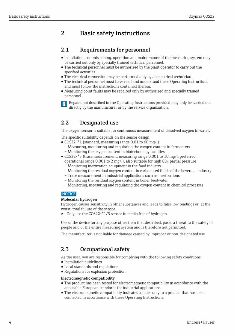
1.1 Warnings
Structure of information Meaning
LDANGERCauses (/consequences)Consequences of non-compliance(if applicable)‣ Corrective action
This symbol alerts you to a dangerous situation.Failure to avoid the dangerous situation will result in a fatal or seriousinjury.
LWARNINGCauses (/consequences)Consequences of non-compliance(if applicable)‣ Corrective action
This symbol alerts you to a dangerous situation.Failure to avoid the dangerous situation can result in a fatal or seriousinjury.
LCAUTIONCauses (/consequences)Consequences of non-compliance(if applicable)‣ Corrective action
This symbol alerts you to a dangerous situation.Failure to avoid this situation can result in minor or more serious injuries.
NOTICECause/situationConsequences of non-compliance(if applicable)‣ Action/note
This symbol alerts you to situations which may result in damage toproperty.
1.2 Symbols
Symbol Meaning
Additional information, tips
Permitted or recommended
Not permitted or not recommended
Reference to device documentation
Reference to page
Reference to graphic
Result of a step
Basic safety instructions Oxymax COS22
4 Endress+Hauser
2 Basic safety instructions
2.1 Requirements for personnel• Installation, commissioning, operation and maintenance of the measuring system may
be carried out only by specially trained technical personnel.• The technical personnel must be authorized by the plant operator to carry out the
specified activities.• The electrical connection may be performed only by an electrical technician.• The technical personnel must have read and understood these Operating Instructions
and must follow the instructions contained therein.• Measuring point faults may be repaired only by authorized and specially trained
personnel.
Repairs not described in the Operating Instructions provided may only be carried outdirectly by the manufacturer or by the service organization.
2.2 Designated useThe oxygen sensor is suitable for continuous measurement of dissolved oxygen in water.
The specific suitability depends on the sensor design:• COS22-*1 (standard, measuring range 0.01 to 60 mg/l)
– Measuring, monitoring and regulating the oxygen content in fermenters– Monitoring the oxygen content in biotechnology facilities
• COS22-*3 (trace measurement, measuring range 0.001 to 10 mg/l, preferredoperational range 0.001 to 2 mg/l), also suitable for high CO2 partial pressure– Monitoring inertization equipment in the food industry– Monitoring the residual oxygen content in carbonated fluids of the beverage industry– Trace measurement in industrial applications such as inertizations– Monitoring the residual oxygen content in boiler feedwater– Monitoring, measuring and regulating the oxygen content in chemical processes
NOTICEMolecular hydrogenHydrogen causes sensitivity in other substances and leads to false low readings or, at theworst, total failure of the sensor.‣ Only use the COS22-*1/3 sensor in media free of hydrogen.
Use of the device for any purpose other than that described, poses a threat to the safety ofpeople and of the entire measuring system and is therefore not permitted.
The manufacturer is not liable for damage caused by improper or non-designated use.
2.3 Occupational safetyAs the user, you are responsible for complying with the following safety conditions:• Installation guidelines• Local standards and regulations• Regulations for explosion protection
Electromagnetic compatibility• The product has been tested for electromagnetic compatibility in accordance with the
applicable European standards for industrial applications.• The electromagnetic compatibility indicated applies only to a product that has been
connected in accordance with these Operating Instructions.
Oxymax COS22 Basic safety instructions
Endress+Hauser 5
2.4 Operational safety1. Before commissioning the entire measuring point, verify that all connections are
correct. Ensure that electrical cables and hose connections are undamaged.
2. Do not operate damaged products, and safeguard them to ensure that they are notoperated inadvertently. Label the damaged product as defective.
3. If faults cannot be rectified:Take the products out of operation and safeguard them to ensure that they are notoperated inadvertently.
2.5 Product safetyThe product is designed to meet state-of-the-art safety requirements, has been tested, andleft the factory in a condition in which it is safe to operate. The relevant regulations andEuropean standards have been observed.
Device description, function Oxymax COS22
6 Endress+Hauser
3 Device description, function
3.1 Amperometric measuring principleThe oxygen molecules that diffuse through the membrane are reduced at the cathode tohydroxide ions (OH-). At the anode, silver is oxidized to silver ions (Ag+) (this forms asilver halide layer). A current flows due to the electron donation at the cathode and theelectron acceptance at the anode. Under constant conditions, this flow is proportional tothe oxygen content of the medium. This current is converted in the transmitter andindicated on the display as an oxygen concentration in mg/l, µg/l, ppm, ppb or Vol%, as asaturation index in % SAT or as an oxygen partial pressure in hPa.
3.2 Sensor design
1 2 3 4 5
789 6
A0011868
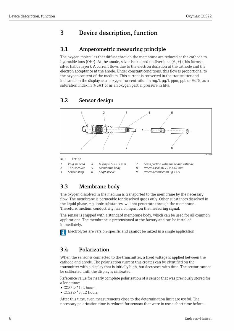
1 COS22123
Plug-in headThrust collarSensor shaft
456
O-ring 8.5 x 1.5 mmMembrane bodyShaft sleeve
789
Glass portion with anode and cathodeProcess seal 10.77 x 2.62 mmProcess connection Pg 13.5
3.3 Membrane bodyThe oxygen dissolved in the medium is transported to the membrane by the necessaryflow. The membrane is permeable for dissolved gases only. Other substances dissolved inthe liquid phase, e.g. ionic substances, will not penetrate through the membrane.Therefore, medium conductivity has no impact on the measuring signal.
The sensor is shipped with a standard membrane body, which can be used for all commonapplications. The membrane is pretensioned at the factory and can be installedimmediately.
Electrolytes are version-specific and cannot be mixed in a single application!
3.4 PolarizationWhen the sensor is connected to the transmitter, a fixed voltage is applied between thecathode and anode. The polarization current this creates can be identified on thetransmitter with a display that is initially high, but decreases with time. The sensor cannotbe calibrated until the display is calibrated.
Reference value for nearly complete polarization of a sensor that was previously stored fora long time:• COS22-*1: 2 hours• COS22-*3: 12 hours
After this time, even measurements close to the determination limit are useful. Thenecessary polarization time is reduced for sensors that were in use a short time before.
Oxymax COS22 Incoming acceptance and product identification
Endress+Hauser 7
4 Incoming acceptance and productidentification
4.1 Incoming acceptance1. Verify that the packaging is undamaged.
Notify your supplier of any damage to the packaging.Keep the damaged packaging until the matter has been settled.
2. Verify that the contents are undamaged. Notify your supplier of any damage to the delivery contents.
Keep the damaged products until the matter has been settled.
3. Check the delivery for completeness. Check it against the delivery papers and your order.
4. Pack the product for storage and transportation in such a way that it is protectedagainst impact and moisture. The original packaging offers the best protection.
The permitted ambient conditions must be observed (see "Technical data").
If you have any questions, please contact your supplier or your local sales center.
4.2 Product identification
4.2.1 NameplateThe nameplate provides you with the following information on your device:• Manufacturer identification• Order code• Extended order code• Serial number• Safety information and warnings
Compare the data on the nameplate with your order.
4.2.2 Product identification
Product pagewww.endress.com/cos22
Interpreting the order codeThe order code and serial number of your product can be found in the following locations:• On the nameplate• In the delivery papers
Obtaining information on the product1. Go to the product page for your product on the Internet.
2. In the navigation area on the right-hand side, select "Check your device features"under "Device support". An additional window opens.
3. Enter the order code from the nameplate into the search field. You will receive information on each feature (selected option) of the order code.
Incoming acceptance and product identification Oxymax COS22
8 Endress+Hauser
4.3 Scope of deliveryThe scope of delivery comprises:
• Oxygen sensor with watering cap (filled with tap water) for protecting the membrane• Electrolyte, 1 bottle, 10 ml (0.34 fl.oz.)• Tool to push out the membrane body• Brief Operating Instructions
4.4 Certificates and approvals
4.4.1 mark
Declaration of ConformityThe product meets the requirements of the harmonized European standards. As such, itcomplies with the legal specifications of the EC directives. The manufacturer confirmssuccessful testing of the product by affixing to it the mark.
4.4.2 Material certificates
Manufacturer declaration of FDA compatibilityThe manufacturer declares the use of FDA-listed materials.Ask your Sales Center for the certificates.
Product FDA certificate for
COS22-****22 Membrane, O-rings, process seal
COS22Z-*2*2 Membrane, O-rings, process seal
COS22-****23 Membrane, O-rings
COS22Z-*2*3 Membrane, O-rings
Material test certificateA test certificate 3.1 in accordance with EN10204 is supplied depending on the version (→Product Configurator on the product page).
EHEDGCompliance with EHEDG's criteria for hygienic design• TÜV Rheinland, Apeldorn, Netherlands• Certificate type: Type EL Class I
Oxymax COS22 Installation
Endress+Hauser 9
5 Installation
5.1 Installation conditions
5.1.1 Orientation
10° 10° Not permissible!Not permissible!
Permissible angle of installation
A0005584-EN
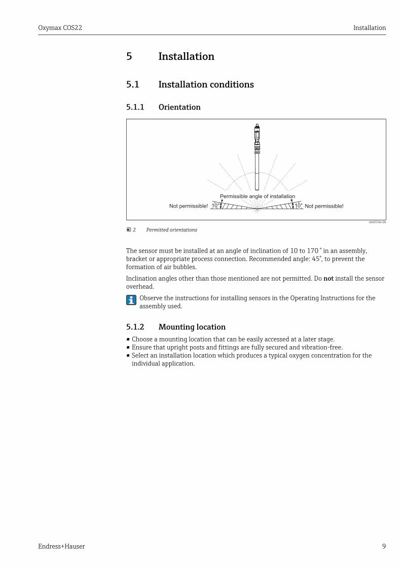
2 Permitted orientations
The sensor must be installed at an angle of inclination of 10 to 170 ° in an assembly,bracket or appropriate process connection. Recommended angle: 45°, to prevent theformation of air bubbles.
Inclination angles other than those mentioned are not permitted. Do not install the sensoroverhead.
Observe the instructions for installing sensors in the Operating Instructions for theassembly used.
5.1.2 Mounting location• Choose a mounting location that can be easily accessed at a later stage.• Ensure that upright posts and fittings are fully secured and vibration-free.• Select an installation location which produces a typical oxygen concentration for the
individual application.
Installation Oxymax COS22
10 Endress+Hauser
5.2 Mounting the sensor
5.2.1 Measuring systemA complete measuring system comprises:• An Oxymax COS22 oxygen sensor• A transmitter, e.g. Liquisys COM2x3• Measuring cable COK21• Optional: an assembly, e.g. permanent installation assembly CPA442, flow assembly
CPA240, or retractable assembly CPA875
1 2
34
A0024029
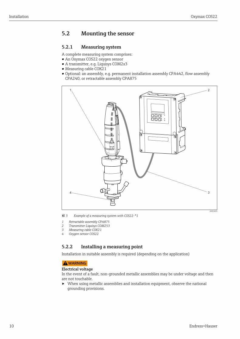
3 Example of a measuring system with COS22-*1
1 Retractable assembly CPA8752 Transmitter Liquisys COM2533 Measuring cable COK214 Oxygen sensor COS22
5.2.2 Installing a measuring pointInstallation in suitable assembly is required (depending on the application)
LWARNINGElectrical voltageIn the event of a fault, non-grounded metallic assemblies may be under voltage and thenare not touchable.‣ When using metallic assemblies and installation equipment, observe the national
grounding provisions.
Oxymax COS22 Installation
Endress+Hauser 11
For a complete installation of a measuring point, proceed as follows:
1. Install a retractable or a flow assembly (if used) into the process.
2. Connect the water supply to the rinse connections (if you use an assembly withcleaning function).
3. Install and connect the oxygen sensor.
NOTICEInstallation errorCable open circuit, loss of sensor due to cable separation, unscrewing of membrane cap‣ Do not install the sensor suspended from the cable.‣ Screw the sensor into the assembly so that the cable is not twisted.‣ When installing or uninstalling the sensor body, hold it tightly. Turn using only the
hexagonal nut on the armored coupling. Otherwise you might unscrew the membranecap. This will then remain in the assembly or process.
‣ Avoid exerting excessive tensile force on the cable (e.g. from jerky pulling).‣ Select an installation location that is easy to access for later calibrations.
5.3 Installation examples
5.3.1 Permanent installation (CPA442)The permanent installation assembly CPA442 enables easy adaptation of a sensor tonearly any process connections from Ingold nozzles to Varivent or Tri-Clamp connections.This kind of installation is very well suited for tanks and larger pipes. You will achieve adefined immersion depth of the sensor into the medium in the simplest way.
5.3.2 Flow assembly
CPA240The flow assembly CPA240 offers up to three installation spaces for sensors with a shaftdiameter of 12 mm (0.47"), a shaft length of 120 mm (4.7"), and a Pg 13.5 processconnection. It very well suited for use in pipelines or hose connections. To prevent
Installation Oxymax COS22
12 Endress+Hauser
measured error with trace measurements, pay particular attention to complete ventilationof the assembly.
A0005720
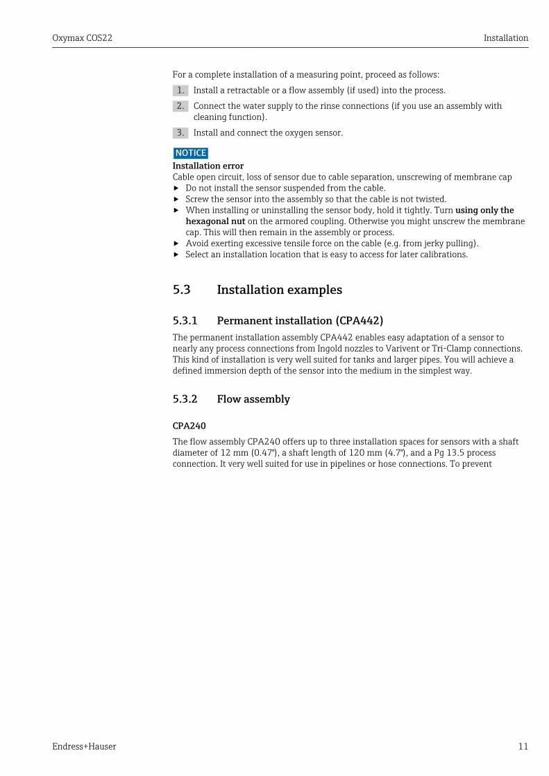
4 Flow assembly CPA240 with protective cover
1
7
6
5
3
2
4
A0005721
5 Bypass installation
1 Main pipe2 Medium removal3, 6 Manually actuated or solenoid valves4 Sampling5 Flow assembly with installed sensor7 Medium return
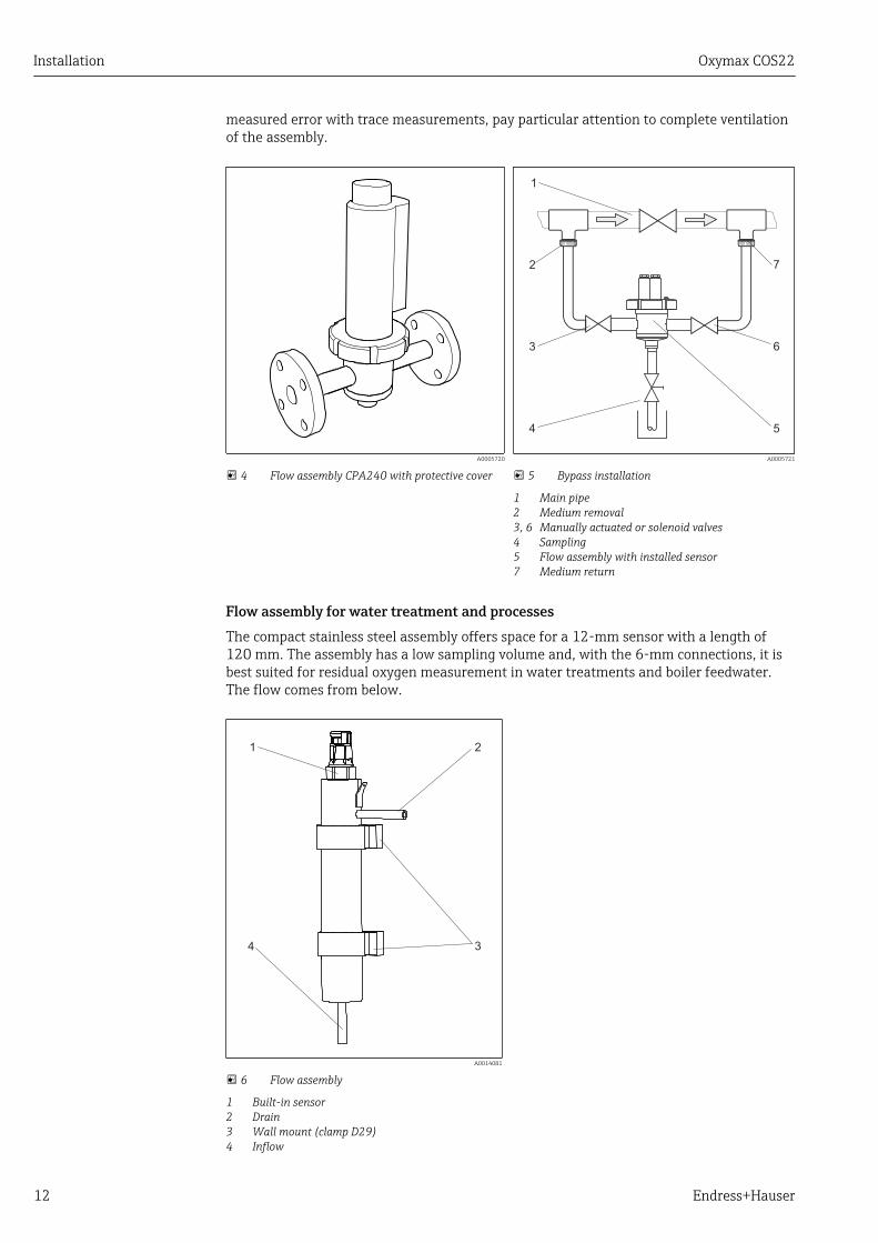
Flow assembly for water treatment and processesThe compact stainless steel assembly offers space for a 12-mm sensor with a length of120 mm. The assembly has a low sampling volume and, with the 6-mm connections, it isbest suited for residual oxygen measurement in water treatments and boiler feedwater.The flow comes from below.
1 2
34
A0014081
6 Flow assembly
1 Built-in sensor2 Drain3 Wall mount (clamp D29)4 Inflow
Oxymax COS22 Installation
Endress+Hauser 13
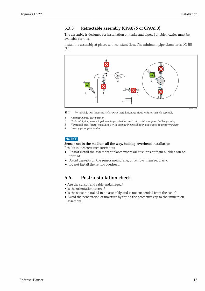
5.3.3 Retractable assembly (CPA875 or CPA450)The assembly is designed for installation on tanks and pipes. Suitable nozzles must beavailable for this.
Install the assembly at places with constant flow. The minimum pipe diameter is DN 80(3").
5
3
41
2
3
4
2
A0005722-EN
7 Permissible and impermissible sensor installation positions with retractable assembly
1 Ascending pipe, best position2 Horizontal pipe, sensor top down, impermissible due to air cushion or foam bubble forming3 Horizontal pipe, lateral installation with permissible installation angle (acc. to sensor version)4 Down pipe, impermissible
NOTICESensor not in the medium all the way, buildup, overhead installationResults in incorrect measurements‣ Do not install the assembly at places where air cushions or foam bubbles can be
formed.‣ Avoid deposits on the sensor membrane, or remove them regularly.‣ Do not install the sensor overhead.
5.4 Post-installation check• Are the sensor and cable undamaged?• Is the orientation correct?• Is the sensor installed in an assembly and is not suspended from the cable?• Avoid the penetration of moisture by fitting the protective cap to the immersion
assembly.
Electrical connection Oxymax COS22
14 Endress+Hauser
6 Electrical connectionLWARNING
Device is liveIncorrect connection may result in injury or death.‣ The electrical connection may be performed only by an electrical technician.‣ The electrical technician must have read and understood these Operating Instructions
and must follow the instructions contained therein.‣ Prior to commencing connection work, ensure that no voltage is present on any cable.
6.1 Connecting the sensor
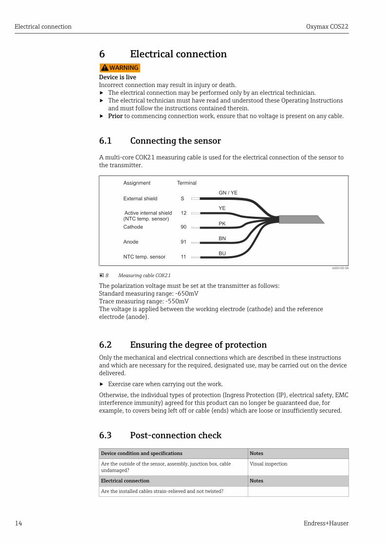
A multi-core COK21 measuring cable is used for the electrical connection of the sensor tothe transmitter.
PK
GN / YE
BN
YE
BU
S
12
90
91
11
Assignment Terminal
External shield
Cathode
Anode
NTC temp. sensor
Active internal shield(NTC temp. sensor)
A0005583-EN
8 Measuring cable COK21
The polarization voltage must be set at the transmitter as follows:Standard measuring range: -650mVTrace measuring range: -550mVThe voltage is applied between the working electrode (cathode) and the referenceelectrode (anode).
6.2 Ensuring the degree of protectionOnly the mechanical and electrical connections which are described in these instructionsand which are necessary for the required, designated use, may be carried out on the devicedelivered.
‣ Exercise care when carrying out the work.
Otherwise, the individual types of protection (Ingress Protection (IP), electrical safety, EMCinterference immunity) agreed for this product can no longer be guaranteed due, forexample, to covers being left off or cable (ends) which are loose or insufficiently secured.
6.3 Post-connection check
Device condition and specifications Notes
Are the outside of the sensor, assembly, junction box, cableundamaged?
Visual inspection
Electrical connection Notes
Are the installed cables strain-relieved and not twisted?
Oxymax COS22 Electrical connection
Endress+Hauser 15
Device condition and specifications Notes
Is a sufficient length of the cable cores stripped, and is itpositioned in the terminal correctly?
Check the fit (by pulling gently)
Are all the screws terminals properly tightened? Tighten
Are all cable entries mounted, tightened and leak-tight? For lateral cable entries, make sure thecables loop downwards to allow water todrip offAre all cable entries installed downwards or mounted laterally?
Calibration and adjustment Oxymax COS22
16 Endress+Hauser
7 Calibration and adjustmentCalibration is a means of adapting the transmitter to the characteristic values of thesensor.
Calibration of the sensor is required after:• Initial commissioning• Changing the membrane or electrolyte• Long pauses in operation without power supply
Within the framework of system monitoring and supervision, for example, the calibrationcan also be cyclically monitored (at typical time intervals, depending on operatingexperience) or renewed.
7.1 Types of calibrationYou can carry out a slope or zero point calibration for the sensor.
In most applications, single-point calibration in the presence of oxygen is sufficient(=calibration of the sensor slope). When switching from process to calibration conditions,you have to allow a longer settling time for the sensor.
The additional calibration of the zero point improves the accuracy of the measurementresults at trace concentrations. You can calibrate the zero point using nitrogen (min.99.995%) or oxygen-free water. Make sure that the sensor is polarized and the measuredvalue is settled at the zero point (at least 20-30 minutes) to prevent later incorrectmeasurements at trace concentrations.
The following describes calibration of the slope in air (saturated with water vapor) as theeasiest and recommended calibration method. However, this type of calibration is possibleonly if the air temperature is ≥ 0 °C (32 °F).
7.2 Calibration in air1. Remove the sensor from the medium.
2. Clean the outside of the sensor with a damp cloth.
3. Allow approx. 20 minutes for the sensor temperature to adapt to the ambient air.Make sure that the sensor is not exposed to any direct ambient influences (directsunlight, drafts) during this time.
4. When the measured value display on the transmitter is stable, carry out thecalibration according to the operating instructions for the transmitter. Pay particularattention to the software settings for the stability criteria for calibration.
5. Where necessary:Adjust the sensor.
6. Then insert the sensor into the medium.
Make sure you comply with the instructions for calibration in the OperatingInstructions of the transmitter.
Oxymax COS22 Calibration and adjustment
Endress+Hauser 17
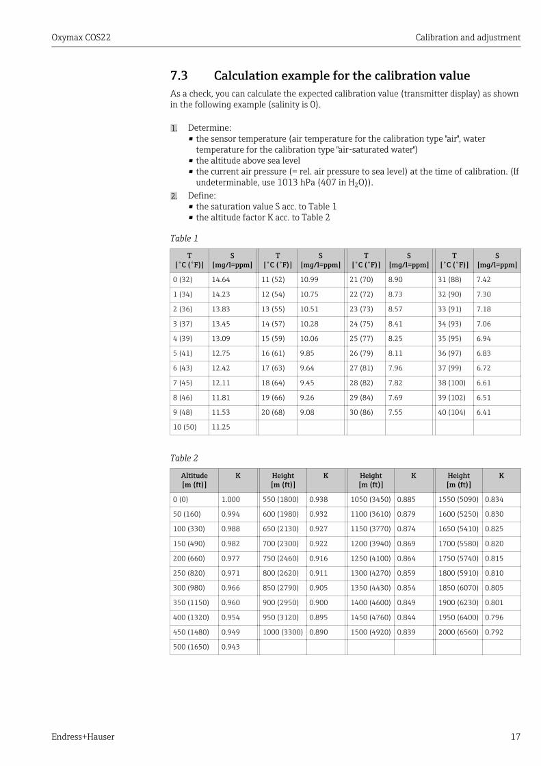
7.3 Calculation example for the calibration valueAs a check, you can calculate the expected calibration value (transmitter display) as shownin the following example (salinity is 0).
1. Determine:• the sensor temperature (air temperature for the calibration type "air", water
temperature for the calibration type "air-saturated water")• the altitude above sea level• the current air pressure (= rel. air pressure to sea level) at the time of calibration. (If
undeterminable, use 1013 hPa (407 in H2O)).2. Define:
• the saturation value S acc. to Table 1• the altitude factor K acc. to Table 2
Table 1
T[˚C (˚F)]
S[mg/l=ppm]
T[˚C (˚F)]
S[mg/l=ppm]
T[˚C (˚F)]
S[mg/l=ppm]
T[˚C (˚F)]
S[mg/l=ppm]
0 (32) 14.64 11 (52) 10.99 21 (70) 8.90 31 (88) 7.42
1 (34) 14.23 12 (54) 10.75 22 (72) 8.73 32 (90) 7.30
2 (36) 13.83 13 (55) 10.51 23 (73) 8.57 33 (91) 7.18
3 (37) 13.45 14 (57) 10.28 24 (75) 8.41 34 (93) 7.06
4 (39) 13.09 15 (59) 10.06 25 (77) 8.25 35 (95) 6.94
5 (41) 12.75 16 (61) 9.85 26 (79) 8.11 36 (97) 6.83
6 (43) 12.42 17 (63) 9.64 27 (81) 7.96 37 (99) 6.72
7 (45) 12.11 18 (64) 9.45 28 (82) 7.82 38 (100) 6.61
8 (46) 11.81 19 (66) 9.26 29 (84) 7.69 39 (102) 6.51
9 (48) 11.53 20 (68) 9.08 30 (86) 7.55 40 (104) 6.41
10 (50) 11.25
Table 2
Altitude[m (ft)]
K Height[m (ft)]
K Height[m (ft)]
K Height[m (ft)]
K
0 (0) 1.000 550 (1800) 0.938 1050 (3450) 0.885 1550 (5090) 0.834
50 (160) 0.994 600 (1980) 0.932 1100 (3610) 0.879 1600 (5250) 0.830
100 (330) 0.988 650 (2130) 0.927 1150 (3770) 0.874 1650 (5410) 0.825
150 (490) 0.982 700 (2300) 0.922 1200 (3940) 0.869 1700 (5580) 0.820
200 (660) 0.977 750 (2460) 0.916 1250 (4100) 0.864 1750 (5740) 0.815
250 (820) 0.971 800 (2620) 0.911 1300 (4270) 0.859 1800 (5910) 0.810
300 (980) 0.966 850 (2790) 0.905 1350 (4430) 0.854 1850 (6070) 0.805
350 (1150) 0.960 900 (2950) 0.900 1400 (4600) 0.849 1900 (6230) 0.801
400 (1320) 0.954 950 (3120) 0.895 1450 (4760) 0.844 1950 (6400) 0.796
450 (1480) 0.949 1000 (3300) 0.890 1500 (4920) 0.839 2000 (6560) 0.792
500 (1650) 0.943
Calibration and adjustment Oxymax COS22
18 Endress+Hauser
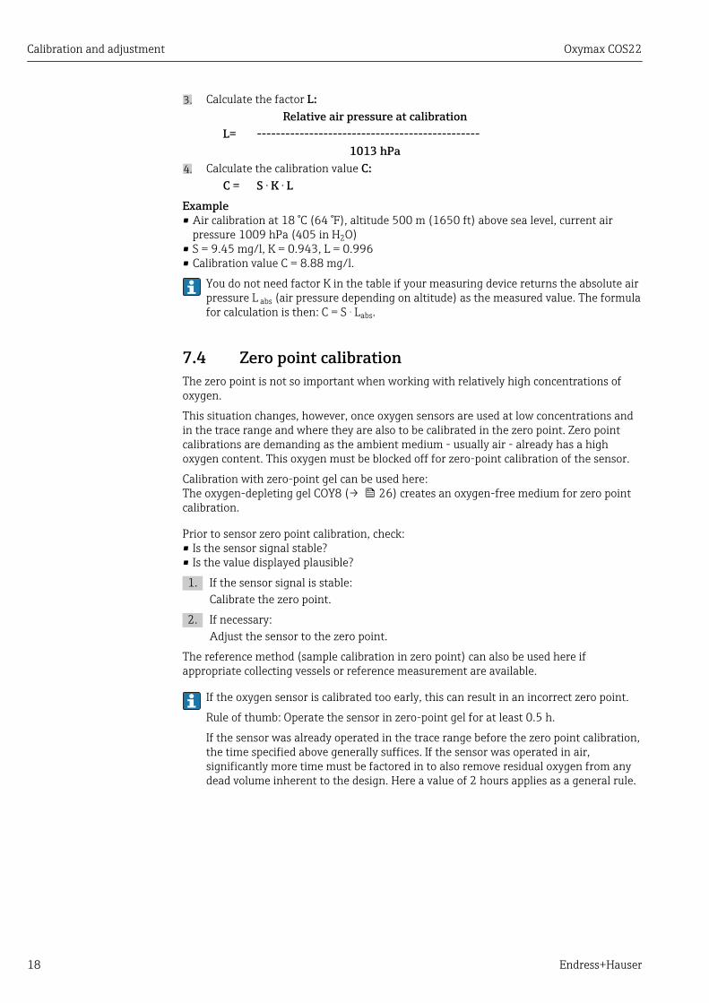
3. Calculate the factor L:Relative air pressure at calibration
L= -----------------------------------------------1013 hPa
4. Calculate the calibration value C:C = S . K . L
Example• Air calibration at 18 °C (64 °F), altitude 500 m (1650 ft) above sea level, current air
pressure 1009 hPa (405 in H2O)• S = 9.45 mg/l, K = 0.943, L = 0.996• Calibration value C = 8.88 mg/l.
You do not need factor K in the table if your measuring device returns the absolute airpressure L abs (air pressure depending on altitude) as the measured value. The formulafor calculation is then: C = S . Labs.
7.4 Zero point calibrationThe zero point is not so important when working with relatively high concentrations ofoxygen.
This situation changes, however, once oxygen sensors are used at low concentrations andin the trace range and where they are also to be calibrated in the zero point. Zero pointcalibrations are demanding as the ambient medium - usually air - already has a highoxygen content. This oxygen must be blocked off for zero-point calibration of the sensor.
Calibration with zero-point gel can be used here:The oxygen-depleting gel COY8 (→ 26) creates an oxygen-free medium for zero pointcalibration.
Prior to sensor zero point calibration, check:• Is the sensor signal stable?• Is the value displayed plausible?
1. If the sensor signal is stable:Calibrate the zero point.
2. If necessary:Adjust the sensor to the zero point.
The reference method (sample calibration in zero point) can also be used here ifappropriate collecting vessels or reference measurement are available.
If the oxygen sensor is calibrated too early, this can result in an incorrect zero point.
Rule of thumb: Operate the sensor in zero-point gel for at least 0.5 h.
If the sensor was already operated in the trace range before the zero point calibration,the time specified above generally suffices. If the sensor was operated in air,significantly more time must be factored in to also remove residual oxygen from anydead volume inherent to the design. Here a value of 2 hours applies as a general rule.
Oxymax COS22 Commissioning
Endress+Hauser 19
8 Commissioning
8.1 Function checkBefore first commissioning, check if:• the sensor is correctly installed• the electrical connection is correct.
If using an assembly with automatic cleaning, check that the cleaning medium (e.g. wateror air) is connected correctly.
LWARNINGEscaping process mediumRisk of injury from high pressure, high temperatures or chemical hazards‣ Before applying compressed air to an assembly with cleaning facility, make sure the
connections are correctly fitted.‣ Do not install the assembly in the process if you cannot make the correct connection
reliably.
8.2 Sensor polarizationNOTICE
Incorrect measurements due to ambient influences‣ Be absolutely certain to avoid direct sunlight on the sensor.‣ Make sure you comply with the instructions for commissioning in the Operating
Instructions of the transmitter.
The sensor has been tested at the factory for proper function and is shipped in ready-to-operate condition.
To prepare for the calibration, carry out the following steps:
1. Pull off the sensor protection cap.
2. Expose the sensor, which should be dry on the outside, to the air atmosphere. The air should be saturated with water vapor. Therefore, install the sensor as
close as possible to a surface of water. However, the sensor membrane mustremain dry during calibration. Therefore, avoid direct contact with the surface ofwater.
3. Connect the sensor to the transmitter.
4. Switch on the transmitter. When the sensor is connected to the transmitter, the polarization takes place
automatically after the power-up of the transmitter.
5. Wait for the polarization time to run out.
Commissioning Oxymax COS22
20 Endress+Hauser
8.3 Sensor calibrationCalibrate the sensor (e.g. air calibration) immediately after the polarization time runs out.
The calibration intervals depend greatly on:• The application• The installation position of the sensor
The following method helps you determine the necessary calibration intervals:
1. Inspect the sensor one month after commissioning. Take it out of the medium anddry it.
2. After 10 minutes, measure the oxygen saturation index in air. Decide depending on the result: If the measured value is not 100 ±2 %SAT, you
must calibrate the sensor. Otherwise, double the length of time to the nextinspection.
3. Proceed as per Point 1 after two, four and/or eight months. In this way, you candetermine the optimum calibration interval for your sensor.
In any case, calibrate the sensor at least once a year.
Oxymax COS22 Troubleshooting
Endress+Hauser 21
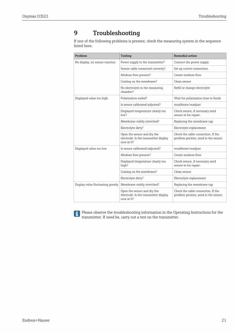
9 TroubleshootingIf one of the following problems is present, check the measuring system in the sequencelisted here.
Problem Testing Remedial action
No display, no sensor reaction Power supply to the transmitter? Connect the power supply
Sensor cable connected correctly? Set up correct connection.
Medium flow present? Create medium flow
Coating on the membrane? Clean sensor
No electrolyte in the measuringchamber?
Refill or change electrolyte
Displayed value too high Polarization ended? Wait for polarization time to finish
Is sensor calibrated/adjusted? recalibrate/readjust
Displayed temperature clearly toolow?
Check sensor, if necessary sendsensor in for repair.
Membrane visibly stretched? Replacing the membrane cap
Electrolyte dirty? Electrolyte replacement
Open the sensor and dry theelectrode. Is the transmitter displaynow at 0?
Check the cable connection. If theproblem persists, send in the sensor.
Displayed value too low Is sensor calibrated/adjusted? recalibrate/readjust
Medium flow present? Create medium flow
Displayed temperature clearly toohigh?
Check sensor, if necessary sendsensor in for repair.
Coating on the membrane? Clean sensor
Electrolyte dirty? Electrolyte replacement
Display value fluctuating greatly Membrane visibly stretched? Replacing the membrane cap
Open the sensor and dry theelectrode. Is the transmitter displaynow at 0?
Check the cable connection. If theproblem persists, send in the sensor.
Please observe the troubleshooting information in the Operating Instructions for thetransmitter. If need be, carry out a test on the transmitter.
Maintenance Oxymax COS22
22 Endress+Hauser
10 MaintenanceTake all the necessary precautions in time to ensure the operational safety and reliabilityof the entire measuring system.
NOTICEEffects on process and process control‣ When carrying out any work on the system, take into account possible repercussions
for process control or the process itself.‣ For your own safety, only use genuine accessories. With genuine parts, the function,
accuracy and reliability are also ensured after maintenance work.
10.1 Maintenance scheduleMaintenance cycles depend to a great extent on the operating conditions.
The following rule of thumb applies:• Constant conditions, e.g. power plant = long cycles (1/2 year)• Greatly varying conditions, e.g. daily CIP cleaning = short cycles (1 month or shorter)
The following method helps you determine the necessary intervals:
1. Inspect the sensor one month after commissioning. Take it out of the medium anddry it.
2. After 10 minutes, measure the oxygen saturation index in air. Decide depending on the result: If the measured value is not 100 ±2 %SAT, you
must maintain the sensor. Otherwise, double the length of time to the nextinspection.
3. Proceed as per Point 1 after two, four and/or eight months. In this way, you candetermine the optimum maintenance interval for your sensor.
Particularly in the case of widely fluctuating process conditions, damage may occur tothe membrane even within a maintenance cycle. You can recognize this byimplausible sensor behavior.
10.2 Maintenance tasksThe following tasks are mandatory:• Clean the sensor and the glass body with anode and cathode (particularly if membrane is
dirty)• Replacement of wear parts or consumables:
– Electrolyte– Membrane body–– Sealing ring
• Check the measuring function:1. Remove the sensor from the medium.2. Clean and dry the membrane.3. After about 10 minutes, measure the oxygen saturation index in air (withoutrecalibration).4. The measured value should be 100 ± 2 % SAT.
• Recalibration (if desired or required)
Oxymax COS22 Maintenance
Endress+Hauser 23
10.3 Clean sensorThe measurement can be corrupted by sensor fouling or malfunction, e.g.:• Buildup on the sensor membrane• causes longer response times and a reduced slope under certain circumstances.
For reliable measurement, the sensor must be cleaned at regular intervals. The frequencyand intensity of the cleaning operation depend on the measuring medium.
Clean the sensor:• before every calibration• at regular intervals during operation as necessary• before returning it for repairs.
Type of soiling Cleaning
Salt deposits Immerse the sensor in drinking water or in 1-5% hydrochloric acid(for a few minutes). Afterwards, rinse it with copious amounts ofwater.
Dirt particles on the sensor shaft andshaft sleeve (not membrane!)
Clean the sensor shaft and sleeve with water and a suitable brush.
Dirt particles on the membrane ormembrane body
Clean the membrane with water and a soft sponge.
After cleaning, rinse the sensor with copious amounts of clean water.
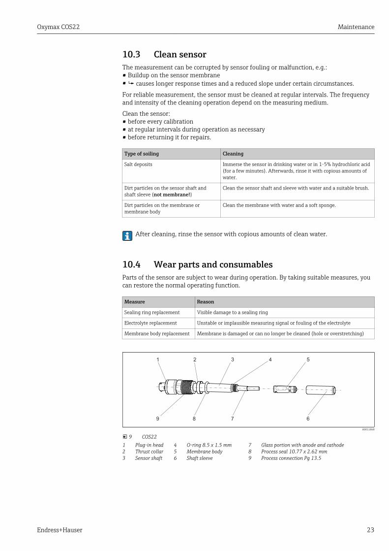
10.4 Wear parts and consumablesParts of the sensor are subject to wear during operation. By taking suitable measures, youcan restore the normal operating function.
Measure Reason
Sealing ring replacement Visible damage to a sealing ring
Electrolyte replacement Unstable or implausible measuring signal or fouling of the electrolyte
Membrane body replacement Membrane is damaged or can no longer be cleaned (hole or overstretching)
1 2 3 4 5
789 6
A0011868
9 COS22123
Plug-in headThrust collarSensor shaft
456
O-ring 8.5 x 1.5 mmMembrane bodyShaft sleeve
789
Glass portion with anode and cathodeProcess seal 10.77 x 2.62 mmProcess connection Pg 13.5
Maintenance Oxymax COS22
24 Endress+Hauser
10.4.1 Replacing sealing ringsThe sealing ring must be replaced if visibly damaged. For replacement, use only originalsealing rings.
The following O-rings can be replaced:• Sealing ring for shaft sleeve: item 4 → 23• Sealing ring for process: item 8
If the sealing ring on the membrane body (item 5) is damaged, you must replace the entiremembrane body.
10.4.2 Replacing electrolyteThe electrolyte is used up slowly during operation. This is caused by electrochemicalsubstance reactions. In de-energized state, no substance reactions take place, and theelectrolyte is not used up. The operating time of the electrolyte is shortened by diffusion ofdissolved gases such as H2S, NH3 or high concentrations of CO2.
Theoretical operating time at pO2 = 210 mbar and T=25 ˚C (77 ˚F)COS22-*1 (standard sensor): > 1.5 yearsCOS22-*3 (trace sensor): > 3 months
LCAUTIONThe standard electrolyte is a strong irritantDanger of severe skin and eye irritation‣ Be absolutely certain to observe the corresponding workplace safety regulations.‣ Wear protective clothing, gloves and goggles when handling the electrolyte.‣ In case of eye contact: Remove contact lenses, flush eyes with water for a few minutes
and contact a doctor.‣ In case of skin contact: Take off wet clothing immediately, wash the skin or take a
shower.
Generally, the following applies:• Changing the electrolyte is mandatory if the membrane body is detached.• Sensors operated close to the zero point consume hardly any chemical electrolyte. The
electrolyte does not have to be replaced for a long period.• Sensors operated at high partial oxygen pressures (> 100 hPa) consume a significant
amount of electrolyte. The electrolyte has to be replaced frequently.• 25 ml electrolyte are enough to fill the membrane body approx. 15 times.
Draining the electrolyte1. Remove the sensor from the medium.
2. Clean the outside of the sensor.
3. Hold the sensor vertically and unscrew the shaft sleeve. The membrane body is either in the shaft sleeve or is still on the glass portion
with the anode and cathode.
4. Remove the membrane body. For this purpose, use the tool provided to push out themembrane body.
5. Drain the membrane body and flush it with potable water.
Top up the electrolyte and install the membrane body1. Fill fresh electrolyte from the supply bottle into the membrane body.
2. Remove all air bubbles from the electrolyte by tapping the side of the membrane body(using a pen or pencil, for example).
3. Hold the sensor vertically and carefully push the membrane body, filled withelectrolyte, on the glass portion.
Oxymax COS22 Maintenance
Endress+Hauser 25
4. Carefully screw on the shaft sleeve as far as it will go.
After replacing, the sensor must be repolarized and recalibrated. Then insert thesensor into the medium and check that no alarm is displayed on the transmitter.
10.4.3 Replacing membrane body
Removing the membrane body1. Remove the sensor from the medium.
2. Clean the outside of the sensor.
3. Hold the sensor vertically and unscrew the shaft sleeve. The membrane body is either in the shaft sleeve or is still on the glass portion
with the anode and cathode.
4. Remove the membrane body. For this purpose, use the tool provided to push out themembrane body.
5. Dispose of the old membrane body and the old electrolyte.
6. Take a new membrane body out of its packaging.
Top up the electrolyte and install the membrane body1. Fill fresh electrolyte from the supply bottle into the membrane body.
2. Remove all air bubbles from the electrolyte by tapping the side of the membrane body(using a pen or pencil, for example).
3. Hold the sensor vertically and carefully push the membrane body, filled withelectrolyte, on the glass portion.
4. Carefully screw on the shaft sleeve as far as it will go.
After replacing, the sensor must be repolarized and recalibrated. Then insert thesensor into the medium and check that no alarm is displayed on the transmitter.
10.4.4 Replacing glass body with cathodeNOTICE
Polishing the cathode can cause impaired function or total failure of the sensor.‣ Do not clean the cathode mechanically.
If the cathode is coated, replace the glass body:
1. Hold the sensor vertically and unscrew the shaft sleeve: item 6 .
2. If the membrane body (item 5) remains on the glass body (item 7) and not in theshaft sleeve, remove it from the glass body.
3. Flush the glass body, along with the anode and cathode, using distilled water.
4. Pull the used glass body out of the holder.
5. Dry the inside of the electrode holder.
6. Plug a new glass body (from the membrane kit) into the holder so that it fits. Ensurethat you do not damage the electrical contact pins.
7. Fill the membrane body with electrolyte then screw the shaft sleeve back on.
Accessories Oxymax COS22
26 Endress+Hauser
11 AccessoriesThe following are the most important accessories available at the time thisdocumentation was issued. For accessories not listed here, please contact your serviceor sales office.
11.1 Assemblies (selection)Cleanfit CPA875• Retractable process assembly for sterile and hygienic applications• For in-line measurement with standard 12 mm sensors for parameters such as pH, ORP
and oxygen• Product Configurator on the product page: www.endress.com/cpa875
Technical Information TI01168C
Flowfit CPA240• pH/redox flow assembly for processes with stringent requirements• Product Configurator on the product page: www.endress.com/cpa240
Technical Information TI00179C
Unifit CPA442• Installation assembly for food, biotechnology and pharmaceutics• With EHEDG and 3A certificate• Product Configurator on the product page: www.endress.com/cpa442
Technical Information TI00306C
Cleanfit CPA450• Manual retractable assembly for installing 120 mm sensors in tanks and pipes• Product Configurator on the product page: www.endress.com/cpa450
Technical Information TI00183C
Flow assembly• For sensors with Ø 12 mm and length 120 mm• Compact stainless steel assembly with low sampling volume• Order No. Order No.: 71042404
11.2 Measuring cable
11.2.1 Cable for COS22COK21• Cable length 3 m (9.8 ft)
Order No. 51505870• Cable length 10 m (33 ft)
Order No. 51505868
11.3 Zero-point gelCOY8Zero-point gel for oxygen sensors• Oxygen-depleting gel for test purposes• Product Configurator on the product page: www.endress.com/coy8
Technical Information TI01244C

Oxymax COS22 Accessories
Endress+Hauser 27
11.4 Maintenance kitCOS22Z• Service Kit, COS22 and COS22D• Ordering information: www.endress.com/cos22d under "Accessories/spare parts"
Repair Oxymax COS22
28 Endress+Hauser
12 Repair
12.1 Spare parts and consumablesCOS22Z• Service Kit, COS22 and COS22D• Ordering information: www.endress.com/cos22d under "Accessories/spare parts"
12.2 ReturnThe product must be returned if repairs or a factory calibration are required, or if thewrong product was ordered or delivered. As an ISO-certified company and also due to legalregulations, Endress+Hauser is obliged to follow certain procedures when handling anyreturned products that have been in contact with medium.
To ensure swift, safe and professional device returns, please read the return proceduresand conditions at www.endress.com/support/return-material.
12.3 DisposalThe device contains electronic components and must therefore be disposed of inaccordance with regulations on the disposal of electronic waste.
Observe the local regulations.
Oxymax COS22 Technical data
Endress+Hauser 29
13 Technical data
13.1 Input
Measured values Dissolved oxygen [mg/l, µg/l, ppm, ppb or % SAT or hPa]
Temperature [˚C, ˚F]
Measuring ranges Measuring ranges apply for 20 ˚ (68 ˚F) and 1013 hPa (15 psi)
Measuring range Optimum operational range 1)
COS22-*1 0.01 to 60 mg/l0 to 600 % SAT0 to 1200 hPa (0 to 6 psi)0 to 100 Vol%
0.01 to 20 mg/l0 to 200 % SAT0 to 400 hPa (0 to 6 psi)0 to 40 Vol%
COS22-*3 0.001 to 10 mg/l0 to 120 % SAT0 to 250 hPa (0 to 6 psi)0 to 25 Vol%
0.001 to 2 mg/l0 to 20 % SAT0 to 40 hPa (0 to 6 psi)0 to 4 Vol%
1) Applications in this range guarantee a long service life and minimum maintenance
13.2 Performance characteristics
Response time From air to nitrogen at reference operating conditions:• t90 : < 30 s• t98 : < 60 s
reference operatingconditions
Reference temperature: 25 ˚C (77 ˚F)Reference pressure: 1013 hPa (15 psi)Reference application: Air-saturated water
Signal current in air COS22-*1 (standard sensor): 40 to 100 nACOS22-*3 (trace sensor): 210 to 451 nA
Zero current COS22-*1 (standard sensor): < 0.1 % of the signal current in airCOS22-*3 (trace sensor): < 0.03 % of the signal current in air
Measured value resolution COS22-*1 (standard sensor): 10 ppb in aqueous, 0.2 hPa or 0.02 Vol% ingaseous media
COS22-*3 (trace sensor): 1 ppb in aqueous, 0.02 hPa or 0.002 Vol%in gaseous media
Corresponds to the recommended measured value resolution at the transmitter
Maximum measured error COS22-*1 (standard sensor): ≤ ±1 % of measuring range + 10 ppb *
COS22-*3 (trace sensor): ≤ ±1 % of measuring range + 1 ppb ** at reference operating conditions
Technical data Oxymax COS22
30 Endress+Hauser
Long-term drift < 4 % per month in reference operating conditions≤ 1 % per month in operation with reduced oxygen concentration (< 4 Vol% O2)
Influence of the mediumpressure
Pressure compensation not required
Polarization time COS22-*1 (standard sensor): < 30 min for 98% signal value, 2 h for100%
COS22-*3 (trace sensor): < 3 h for 98% signal value, 12 h for 100%
Intrinsic oxygenconsumption
COS22-*1 (standard sensor): Approx. 20 ng/h in air at 25 ˚C (77 ˚F)COS22-*3 (trace sensor): Approx. 100 ng/h in air at 25 ˚C (77 ˚F
Operating time of theelectrolyte
→ 24
Temperature compensation COS22Compensation of the membrane properties depending on the transmitter, recommended:2.4 % per K
13.3 Environment
Ambient temperaturerange
-5 to +135 °C (23 to 275 °F), non-freezing
Storage temperature –5 to +50 ˚C (20 to 120 ˚F) at 95% relative humidity, non-condensing
NOTICEDanger of sensor drying out‣ Store the sensor with the watering cap only (filled with tap water).
Degree of protection IP 68 (10 m (33 ft) head of water at 25 ˚C (77 ˚F) over 45 days, 1 mol/l KCl)
Humidity 0 to 100%, not condensating in area of T-82 connection
13.4 Process
Process temperature -5 to +135 °C (23 to 275 °F), non-freezing
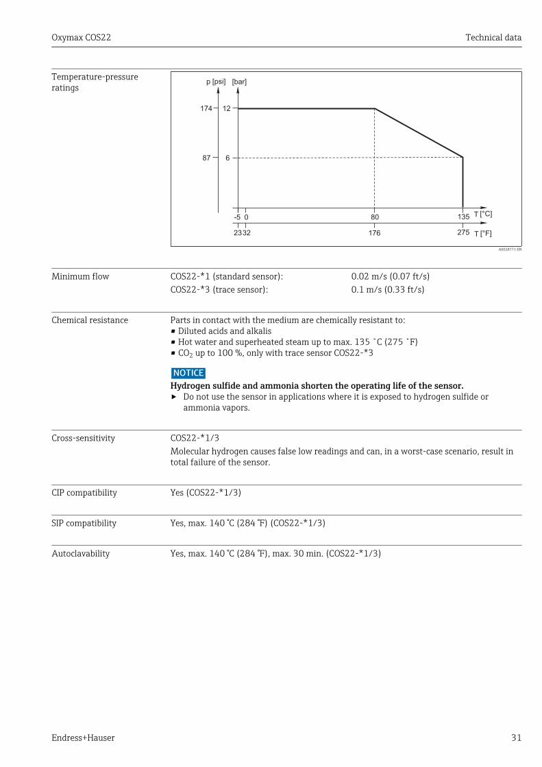
Process pressure Ambient pressure ... 12 bar (... 174 psi) absolute
Oxymax COS22 Technical data
Endress+Hauser 31
Temperature-pressureratings
p
T
[bar]
[°C]
6
12
13580
[psi]
174
87
T [°F]176 275
-5
23
0
32
A0028771-EN
Minimum flow COS22-*1 (standard sensor): 0.02 m/s (0.07 ft/s)COS22-*3 (trace sensor): 0.1 m/s (0.33 ft/s)
Chemical resistance Parts in contact with the medium are chemically resistant to:• Diluted acids and alkalis• Hot water and superheated steam up to max. 135 ˚C (275 ˚F)• CO2 up to 100 %, only with trace sensor COS22-*3
NOTICEHydrogen sulfide and ammonia shorten the operating life of the sensor.‣ Do not use the sensor in applications where it is exposed to hydrogen sulfide or
ammonia vapors.
Cross-sensitivity COS22-*1/3Molecular hydrogen causes false low readings and can, in a worst-case scenario, result intotal failure of the sensor.
CIP compatibility Yes (COS22-*1/3)
SIP compatibility Yes, max. 140 °C (284 °F) (COS22-*1/3)
Autoclavability Yes, max. 140 °C (284 °F), max. 30 min. (COS22-*1/3)
Technical data Oxymax COS22
32 Endress+Hauser
13.5 Mechanical construction
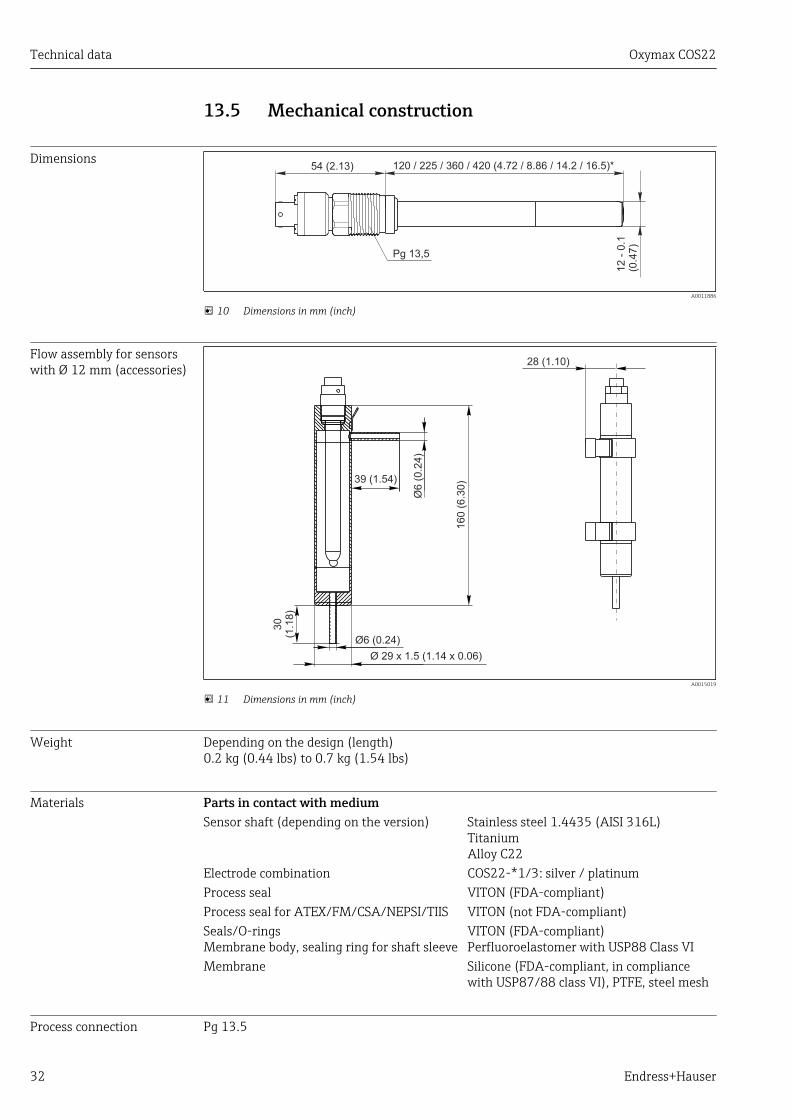
Dimensions
Pg 13,5
54 (2.13) 120 / 225 / 360 / 420 (4.72 / 8.86 / 14.2 / 16.5)*
12 -
0.1
(0.4
7)
A0011886
10 Dimensions in mm (inch)
Flow assembly for sensorswith Ø 12 mm (accessories)
28 (1.10)
Ø6 (
0.2
4)
39 (1.54)
160 (
6.3
0)
30
(1.1
8)
Ø6 (0.24)
Ø 29 x 1.5 (1.14 x 0.06)
A0015019
11 Dimensions in mm (inch)
Weight Depending on the design (length)0.2 kg (0.44 lbs) to 0.7 kg (1.54 lbs)
Materials Parts in contact with mediumSensor shaft (depending on the version) Stainless steel 1.4435 (AISI 316L)
TitaniumAlloy C22
Electrode combination COS22-*1/3: silver / platinumProcess seal VITON (FDA-compliant)Process seal for ATEX/FM/CSA/NEPSI/TIIS VITON (not FDA-compliant)Seals/O-ringsMembrane body, sealing ring for shaft sleeve
VITON (FDA-compliant)Perfluoroelastomer with USP88 Class VI
Membrane Silicone (FDA-compliant, in compliancewith USP87/88 class VI), PTFE, steel mesh
Process connection Pg 13.5

Oxymax COS22 Technical data
Endress+Hauser 33
Surface roughness Ra < 0.38 µm
Temperature sensor NTC 22 kΩ
Electrolyte COS22-*1 (standard sensor): Slightly alkaline electrolyteCOS22-*3 (trace sensor): Neutral electrolyte
Index
34 Endress+Hauser
Index
AAccessories . . . . . . . . . . . . . . . . . . . . . . . . . . . . . . . . 26Adjustment . . . . . . . . . . . . . . . . . . . . . . . . . . . . . . . . 16Ambient temperature range . . . . . . . . . . . . . . . . . . . 30Amperometric measuring principle . . . . . . . . . . . . . . . 6Assemblies . . . . . . . . . . . . . . . . . . . . . . . . . . . . . . . . 26Autoclavability . . . . . . . . . . . . . . . . . . . . . . . . . . . . . 31
CCalibration
Calculation example . . . . . . . . . . . . . . . . . . . . . . . 17In air . . . . . . . . . . . . . . . . . . . . . . . . . . . . . . . . . . 16Types of calibration . . . . . . . . . . . . . . . . . . . . . . . 16Zero point calibration . . . . . . . . . . . . . . . . . . . . . . 18
Cathode . . . . . . . . . . . . . . . . . . . . . . . . . . . . . . . . . . 25Check
Connection . . . . . . . . . . . . . . . . . . . . . . . . . . . . . . 14Function . . . . . . . . . . . . . . . . . . . . . . . . . . . . . . . 19Installation . . . . . . . . . . . . . . . . . . . . . . . . . . . . . 13
Chemical resistance . . . . . . . . . . . . . . . . . . . . . . . . . . 31CIP compatibility . . . . . . . . . . . . . . . . . . . . . . . . . . . . 31Connection
Check . . . . . . . . . . . . . . . . . . . . . . . . . . . . . . . . . . 14Ensuring the degree of protection . . . . . . . . . . . . . 14
Cross-sensitivity . . . . . . . . . . . . . . . . . . . . . . . . . . . . 31Cust. tag number . . . . . . . . . . . . . . . . . . . . . . . . . . . . 10
DDeclaration of Conformity . . . . . . . . . . . . . . . . . . . . . . 8Degree of protection
Ensuring . . . . . . . . . . . . . . . . . . . . . . . . . . . . . . . 14Technical data . . . . . . . . . . . . . . . . . . . . . . . . . . . 30
Designated use . . . . . . . . . . . . . . . . . . . . . . . . . . . . . . 4Device description . . . . . . . . . . . . . . . . . . . . . . . . . . . . 6Disposal . . . . . . . . . . . . . . . . . . . . . . . . . . . . . . . . . . 28
EEHEDG . . . . . . . . . . . . . . . . . . . . . . . . . . . . . . . . . . . . 8Electrical connection . . . . . . . . . . . . . . . . . . . . . . . . . 14Electrolyte
Operating time . . . . . . . . . . . . . . . . . . . . . . . . . . . 24Properties . . . . . . . . . . . . . . . . . . . . . . . . . . . . . . 33Replacement . . . . . . . . . . . . . . . . . . . . . . . . . . . . 24
Environment . . . . . . . . . . . . . . . . . . . . . . . . . . . . . . . 30
FFDA compatibility . . . . . . . . . . . . . . . . . . . . . . . . . . . . 8Function check . . . . . . . . . . . . . . . . . . . . . . . . . . . . . 19
GGlass body . . . . . . . . . . . . . . . . . . . . . . . . . . . . . . . . . 25
HHumidity . . . . . . . . . . . . . . . . . . . . . . . . . . . . . . . . . . 30
IIncoming acceptance . . . . . . . . . . . . . . . . . . . . . . . . . 7
Influence of the medium pressure . . . . . . . . . . . . . . . 30Installation
Check . . . . . . . . . . . . . . . . . . . . . . . . . . . . . . . . . . 13Examples . . . . . . . . . . . . . . . . . . . . . . . . . . . . . . . 11Orientation . . . . . . . . . . . . . . . . . . . . . . . . . . . . . . 9Sensor . . . . . . . . . . . . . . . . . . . . . . . . . . . . . . . . . 10
Installation instructions . . . . . . . . . . . . . . . . . . . . . . . . 9Intrinsic oxygen consumption . . . . . . . . . . . . . . . . . . 30
LLong-term drift . . . . . . . . . . . . . . . . . . . . . . . . . . . . . 30
MMaintenance schedule . . . . . . . . . . . . . . . . . . . . . . . . 22Maintenance tasks . . . . . . . . . . . . . . . . . . . . . . . . . . 22Material test certificate . . . . . . . . . . . . . . . . . . . . . . . . 8Materials . . . . . . . . . . . . . . . . . . . . . . . . . . . . . . . . . 32Maximum measured error . . . . . . . . . . . . . . . . . . . . . 29Measured value resolution . . . . . . . . . . . . . . . . . . . . . 29Measured values . . . . . . . . . . . . . . . . . . . . . . . . . . . . 29Measuring cable . . . . . . . . . . . . . . . . . . . . . . . . . . . . 26Measuring principle . . . . . . . . . . . . . . . . . . . . . . . . . . . 6Measuring ranges . . . . . . . . . . . . . . . . . . . . . . . . . . . 29Measuring system . . . . . . . . . . . . . . . . . . . . . . . . . . . 10Medium pressure . . . . . . . . . . . . . . . . . . . . . . . . . . . 30Membrane body
Description . . . . . . . . . . . . . . . . . . . . . . . . . . . . . . . 6Replace . . . . . . . . . . . . . . . . . . . . . . . . . . . . . . . . 25
Minimum flow . . . . . . . . . . . . . . . . . . . . . . . . . . . . . 31Mode of operation . . . . . . . . . . . . . . . . . . . . . . . . . . . . 6
NNameplate . . . . . . . . . . . . . . . . . . . . . . . . . . . . . . . . . 7
OOccupational safety . . . . . . . . . . . . . . . . . . . . . . . . . . . 4Operational safety . . . . . . . . . . . . . . . . . . . . . . . . . . . . 5Orientation . . . . . . . . . . . . . . . . . . . . . . . . . . . . . . . . . 9
PPerformance characteristics . . . . . . . . . . . . . . . . . . . . 29Polarization . . . . . . . . . . . . . . . . . . . . . . . . . . . . . . . . 6Polarization time . . . . . . . . . . . . . . . . . . . . . . . . . . . . 30Pressure temperature load curve . . . . . . . . . . . . . . . . 31Process . . . . . . . . . . . . . . . . . . . . . . . . . . . . . . . . . . . 30Process connection . . . . . . . . . . . . . . . . . . . . . . . . . . 32Process pressure . . . . . . . . . . . . . . . . . . . . . . . . . . . . 30Process temperature . . . . . . . . . . . . . . . . . . . . . . . . . 30Product identification . . . . . . . . . . . . . . . . . . . . . . . . . 7Product safety . . . . . . . . . . . . . . . . . . . . . . . . . . . . . . . 5
Rreference operating conditions . . . . . . . . . . . . . . . . . . 29Repair . . . . . . . . . . . . . . . . . . . . . . . . . . . . . . . . . . . . 28Replacing sealing rings . . . . . . . . . . . . . . . . . . . . . . . 24Response time . . . . . . . . . . . . . . . . . . . . . . . . . . . . . . 29Return . . . . . . . . . . . . . . . . . . . . . . . . . . . . . . . . . . . 28
Index
Endress+Hauser 35
SSafety
Occupational safety . . . . . . . . . . . . . . . . . . . . . . . . 4Operation . . . . . . . . . . . . . . . . . . . . . . . . . . . . . . . . 5Product . . . . . . . . . . . . . . . . . . . . . . . . . . . . . . . . . 5
Safety instructions . . . . . . . . . . . . . . . . . . . . . . . . . . . . 4Scope of delivery . . . . . . . . . . . . . . . . . . . . . . . . . . . . . 8Sensor
Calibration . . . . . . . . . . . . . . . . . . . . . . . . . . . . . . 20Cleaning . . . . . . . . . . . . . . . . . . . . . . . . . . . . . . . 23Connecting . . . . . . . . . . . . . . . . . . . . . . . . . . . . . . 14Design . . . . . . . . . . . . . . . . . . . . . . . . . . . . . . . . . . 6Mounting . . . . . . . . . . . . . . . . . . . . . . . . . . . . . . . 10Polarization . . . . . . . . . . . . . . . . . . . . . . . . . . . 6, 19
Sensor design . . . . . . . . . . . . . . . . . . . . . . . . . . . . . . . 6Signal current in air . . . . . . . . . . . . . . . . . . . . . . . . . . 29SIP compatibility . . . . . . . . . . . . . . . . . . . . . . . . . . . . 31Spare parts . . . . . . . . . . . . . . . . . . . . . . . . . . . . . . . . 28Storage temperature . . . . . . . . . . . . . . . . . . . . . . . . . 30Surface roughness . . . . . . . . . . . . . . . . . . . . . . . . . . . 33Symbols . . . . . . . . . . . . . . . . . . . . . . . . . . . . . . . . . . . 3
TTechnical data
Environment . . . . . . . . . . . . . . . . . . . . . . . . . . . . 30Input . . . . . . . . . . . . . . . . . . . . . . . . . . . . . . . . . . 29Mechanical construction . . . . . . . . . . . . . . . . . . . . 32Performance characteristics . . . . . . . . . . . . . . . . . 29Process . . . . . . . . . . . . . . . . . . . . . . . . . . . . . . . . 30
Temperature compensation . . . . . . . . . . . . . . . . . . . . 30Temperature sensor . . . . . . . . . . . . . . . . . . . . . . . . . 33Temperature-pressure ratings . . . . . . . . . . . . . . . . . . 31Troubleshooting . . . . . . . . . . . . . . . . . . . . . . . . . . . . 21
UUse . . . . . . . . . . . . . . . . . . . . . . . . . . . . . . . . . . . . . . . 4
WWarnings . . . . . . . . . . . . . . . . . . . . . . . . . . . . . . . . . . 3Wear parts and consumables . . . . . . . . . . . . . . . . . . . 23Weight . . . . . . . . . . . . . . . . . . . . . . . . . . . . . . . . . . . 32
ZZero current . . . . . . . . . . . . . . . . . . . . . . . . . . . . . . . 29Zero solution
Application . . . . . . . . . . . . . . . . . . . . . . . . . . . . . 18Zero-point gel . . . . . . . . . . . . . . . . . . . . . . . . . . . . . . 26

www.addresses.endress.com
*71306871*71306871