operating instructions elite series - hitch pro instructions 26.5k 5th wheel hitch hitch handle jaw...
TRANSCRIPT
30871N – 07JAN15 REV B PCN4742 ©2014 CEQUENT PERFORMANCE PRODUCTS, INC PRINTED IN MEXICOFOR KIT 30871
For Installation Assistance or Technical Help, Call 1-800-632-3290
(1) Provide this Manual to end user.(2) Physically demonstrate hitching and unhitching
procedures in this Manual to end user.(3) Have end user demonstrate that he/she
understands procedures.
DEALER/INSTALLER: END USER:
(1) Read and follow this Manual every time you use hitch. (2) Save this Manual and Hitch Warning Hang Tag for future reference.(3) Pass on copies of Manual and Hitch Warning Hang Tag to any other
user or owner of hitch. (4) Never remove hitch warning decals as shown in Figure 31 of this
manual. If damaged, contact Cequent Performance Products (1-800-632-3290 ) for free replacement.
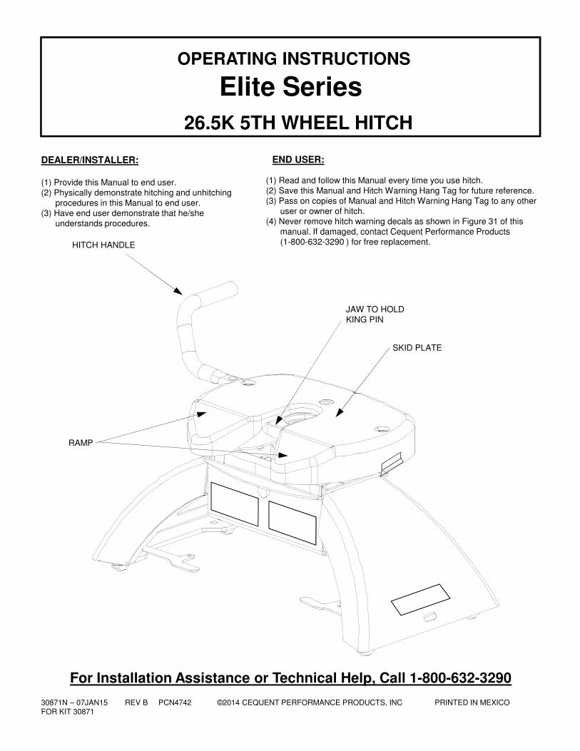
Elite SeriesOPERATING INSTRUCTIONS
26.5K 5TH WHEEL HITCH
HITCH HANDLE
JAW TO HOLDKING PIN
RAMP
SKID PLATE
30871N – 07JAN15 REV B PCN4742 ©2014 CEQUENT PERFORMANCE PRODUCTS, INC PRINTED IN MEXICOFOR KIT 30871
2
1. BEFORE EACH TRIP P. 2 7. HITCHING PROCEDURE P. 122. LUBRICATION P. 3 8. PULL TEST P. 143. ASSEMBLY / ADJUSTMENT P. 4 9. UNHITCHING PROCEDURE P. 154. HITCH INSTALLATION P. 8 10. MAINTENANCE P. 155. HITCH REMOVAL P. 8 11. PARTS EXPLOSION P.166. GUIDELINES FOR MATCHING HITCH P. 9 12. LIMITED LIFETIME WARRANTY P.17
GUIDELINES FOR MATCHING HITCH TRUCK AND TRAILER
WARNING:
Failure to follow all of these instructions may result in death or serious injury
INDEX
If preparing to tow a 5th wheel trailer which you have not rating checked previously, please
consult Figure 16 of Elite Series assembly instructions to verify proper ratings.
BEFORE EACH TRIP:
1. Lubricate skid plate surface of the hitch and pivot pin grease fitting (see Figure on cover of Manual) with automotive type chassis grease or use a plastic lube plate to provide a lubricated surface. Use lithium grease to lubricate pivot points of moving parts within the hitch.
2. Plastic lube plates (Towing Products No. 83001) can be used to avoid messy grease. The plastic lube plate must not exceed 3/16 of an inch in thickness to ensure hitch will operate properly. Lube plate must be 12 inches in diameter or larger to properly distribute king pin weight.
3. Before each trip or maneuver, operate the handle and check that the jaw opens and closes freely.
4. See that all hitch pull pins (# 14, Figure 31) are in place and the spring retaining clips (#15, Figure 31) are installed (Figure 1).
Note that hitch pull pins used with the Elite Series Hitch are 90 degree bent pins and if replacements are needed, please
contact the factory. Check that all four anchor assembly handles are lynch pinned/locked through base arch shell.
Figure 1 : Pins and Clips (Skid Plate cut away view)
Grease Fitting
Lube Skid Plate(With No Lube Plate)
Lube Jaw
RetainingClip
Pull Pin
WARNING:To prevent tilting head
detachment and or
separation of hitch you must
make sure that the anchor
assemblies are properly
installed and pinned, and
the spring retaining clips are
properly installed onto the
½” pull pins before towing.
The spring retaining clips
can easily be seen through
the site holes in the top of
the head.
LynchPin
Anchor Handles overlapped and through Arch Shell
Site Holes (2)
30871N – 07JAN15 REV B PCN4742 ©2014 CEQUENT PERFORMANCE PRODUCTS, INC PRINTED IN MEXICOFOR KIT 30871
3
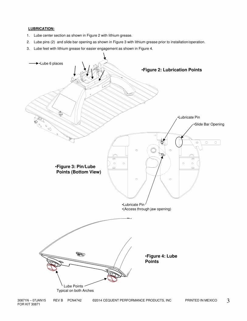
1. Lube center section as shown in Figure 2 with lithium grease.
2. Lube pins (2) and slide bar opening as shown in Figure 3 with lithium grease prior to installation/operation.
3. Lube feet with lithium grease for easier engagement as shown in Figure 4.
•Figure 3: Pin/LubePoints (Bottom View)
•Lubricate Pin
•Lubricate Pin•(Access through jaw opening)
•Figure 2: Lubrication Points
•Lube 6 places
•Slide Bar Opening
LUBRICATION:
•Figure 4: Lube Points
Lube PointsTypical on both Arches
30871N – 07JAN15 REV B PCN4742 ©2014 CEQUENT PERFORMANCE PRODUCTS, INC PRINTED IN MEXICOFOR KIT 30871
4
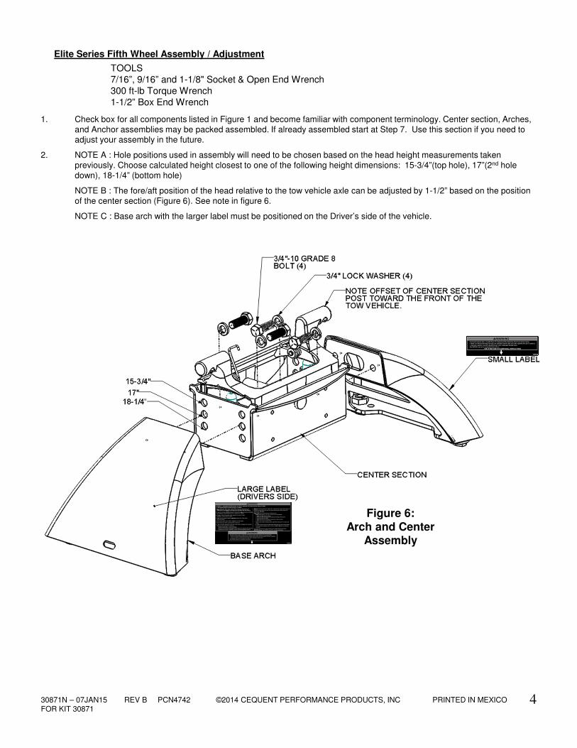
Elite Series Fifth Wheel Assembly / Adjustment
TOOLS
7/16”, 9/16” and 1-1/8" Socket & Open End Wrench
300 ft-lb Torque Wrench
1-1/2” Box End Wrench
1. Check box for all components listed in Figure 1 and become familiar with component terminology. Center section, Arches, and Anchor assemblies may be packed assembled. If already assembled start at Step 7. Use this section if you need to adjust your assembly in the future.
2. NOTE A : Hole positions used in assembly will need to be chosen based on the head height measurements taken previously. Choose calculated height closest to one of the following height dimensions: 15-3/4”(top hole), 17”(2nd hole down), 18-1/4” (bottom hole)
NOTE B : The fore/aft position of the head relative to the tow vehicle axle can be adjusted by 1-1/2” based on the position of the center section (Figure 6). See note in figure 6.
NOTE C : Base arch with the larger label must be positioned on the Driver’s side of the vehicle.
Figure 6:Arch and Center
Assembly
30871N – 07JAN15 REV B PCN4742 ©2014 CEQUENT PERFORMANCE PRODUCTS, INC PRINTED IN MEXICOFOR KIT 30871
5
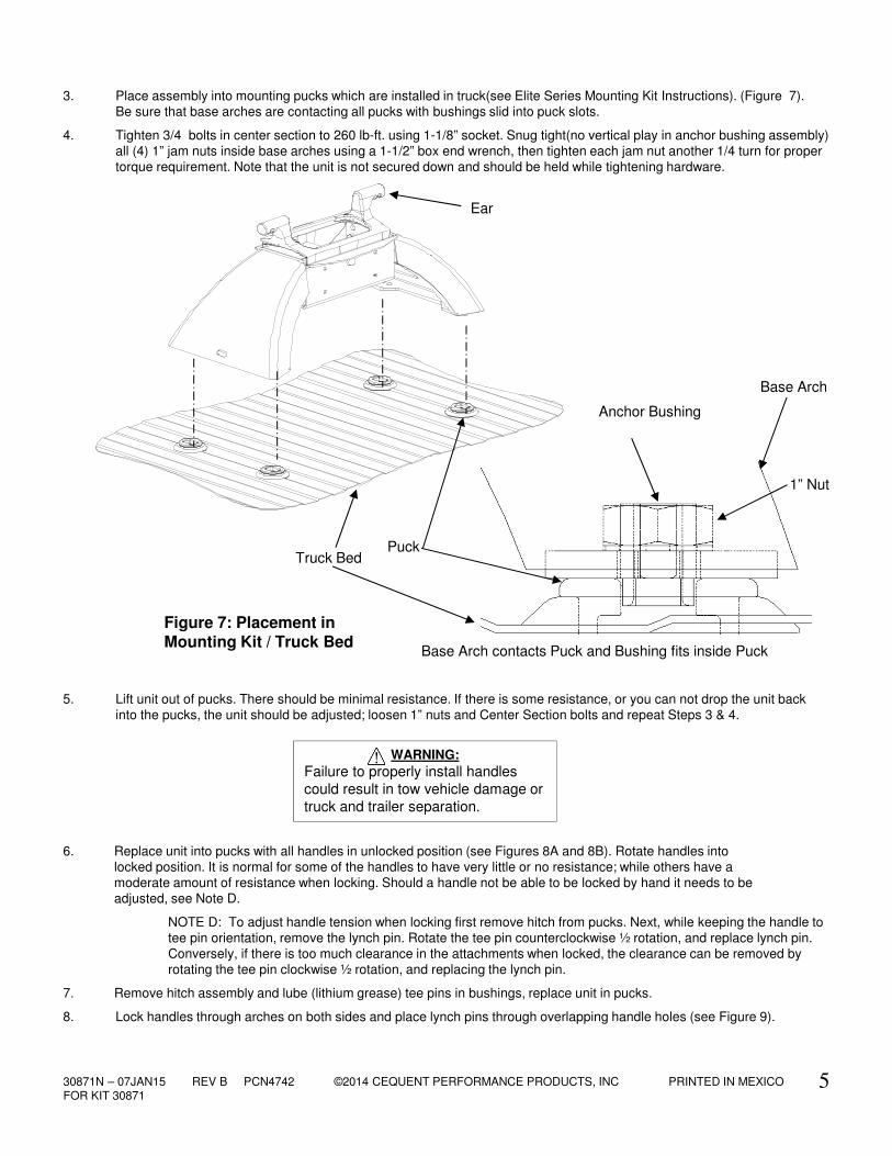
3. Place assembly into mounting pucks which are installed in truck(see Elite Series Mounting Kit Instructions). (Figure 7). Be sure that base arches are contacting all pucks with bushings slid into puck slots.
4. Tighten 3/4 bolts in center section to 260 lb-ft. using 1-1/8” socket. Snug tight(no vertical play in anchor bushing assembly) all (4) 1” jam nuts inside base arches using a 1-1/2” box end wrench, then tighten each jam nut another 1/4 turn for proper torque requirement. Note that the unit is not secured down and should be held while tightening hardware.
Figure 7: Placement in Mounting Kit / Truck Bed
Ear
PuckTruck Bed
Base Arch
Anchor Bushing
Base Arch contacts Puck and Bushing fits inside Puck
1” Nut
5. Lift unit out of pucks. There should be minimal resistance. If there is some resistance, or you can not drop the unit back into the pucks, the unit should be adjusted; loosen 1” nuts and Center Section bolts and repeat Steps 3 & 4.
WARNING:
Failure to properly install handles
could result in tow vehicle damage or
truck and trailer separation.
6. Replace unit into pucks with all handles in unlocked position (see Figures 8A and 8B). Rotate handles into locked position. It is normal for some of the handles to have very little or no resistance; while others have a moderate amount of resistance when locking. Should a handle not be able to be locked by hand it needs to be
adjusted, see Note D.
NOTE D: To adjust handle tension when locking first remove hitch from pucks. Next, while keeping the handle to
tee pin orientation, remove the lynch pin. Rotate the tee pin counterclockwise ½ rotation, and replace lynch pin. Conversely, if there is too much clearance in the attachments when locked, the clearance can be removed by rotating the tee pin clockwise ½ rotation, and replacing the lynch pin.
7. Remove hitch assembly and lube (lithium grease) tee pins in bushings, replace unit in pucks.
8. Lock handles through arches on both sides and place lynch pins through overlapping handle holes (see Figure 9).
30871N – 07JAN15 REV B PCN4742 ©2014 CEQUENT PERFORMANCE PRODUCTS, INC PRINTED IN MEXICOFOR KIT 30871
6
Figure 9: Pinning Anchor Handles
Figure 8A: Anchor Handles in Unlocked Position
Figure 8B: Anchor Handles in Locked Position(overlapped)
Locking Hole Tabs in Handles
overlap and Protrude through
Base Arch
10. If not already installed the Left hand and Right hand torsion springs will need to be added to the center section so that the coil is facing the rear of the truck and wide hook sits over casting as shown in Figure 10. Tighten 1/4-20 X 1 1/2 BOLT with 7/16 socket to 8 ft.lbs.
Figure 10: Torsion Spring Assembly
Right Torsion Spring
Front of Truck
1/4-20 X 1 1/2 BOLT
Tube Spacer
Left Torsion Spring
Washer
30871N – 07JAN15 REV B PCN4742 ©2014 CEQUENT PERFORMANCE PRODUCTS, INC PRINTED IN MEXICOFOR KIT 30871
7
WARNING:
To prevent tilting head
detachment and or
separation of hitch you must
make sure that the anchor
assemblies are properly
installed and pinned, and
the spring retaining clips are
properly installed onto the
½” pull pins before towing.
The spring retaining clips
can easily be seen through
the site holes in the top of
the head.
Figure 12 : Pin and Clip (Skid Plate cut away view)
Grease Fitting
Lube Skid Plate(With No Lube Plate)
Lube Jaw
RetainingClip
Pull Pin
Lynch Pin
Anchor Handles overlapped and through arch shell
Site Holes (2)
WARNING:
Tilting 5th Wheel head can
crush and cut. Keep hands and
fingers clear from this area at
all times (including
placement/removal of head).
Figure 11 : Head Placement
3/8 Carriage bolt (2)
3/8 Lock Washer (2)
3/8 Nut (2)
Grip
11. Place and pin head onto center section (see Figures 11/12). Keep hands clear of ear placement while placing/removing head on/off hitch base as noted on head labels. Head will tilt rearward with proper torsion spring installation (Step 10).
12. Add head handle and handle carriage bolts as shown in Figure 11.
13. Slide handle grip over handle tube (using liquid soap as a lubricant will ease installation).
14. Lube jaw and skid plate (If no lube plate is being used) with automotive type chassis grease (see Figure 12). The jaw pin comes greased from the factory. To insure smooth jaw operation, grease should be added every 6 months to grease fitting on top of head (see Figure 12). Refer to the Lubrication section in this manual.
30871N – 07JAN15 REV B PCN4742 ©2014 CEQUENT PERFORMANCE PRODUCTS, INC PRINTED IN MEXICOFOR KIT 30871
8
HITCH REMOVAL:
HITCH INSTALLATION:
1. Remove puck plugs from all (4) of the pucks in the truck bed (Figure 13) and store for use when hitch is removed.2. Set Elite Series hitch onto the pucks, and rotate handles into unlocked position (approximately perpendicular with
base arch, Figure 14) until hitch drops into pucks on all (4) corners.3. Rotate (4) handles into locked position(with locking holes through base arch shell) and overlapped on each side
(Figure 15).4. Place lynch pins / locks through the overlapping handle holes on each side to anchor hitch into pucks (Figure 15).5. KEEPING HANDS AND FINGERS AWAY FROM THE PINCH POINTS ON EACH SIDE OF THE HEAD, place head
onto center section (Figure 11). Head should tilt rearward on the torsion springs.6. Insert pull pin and clip on each side of the head to attach to the hitch center section (Figure 12).7. Pull up on head to test that all attachments have been completed properly and hitch is ready to tow.
1. Remove pull pin and clip from each side of the head (Figure 12). 2. KEEPING HANDS AND FINGERS AWAY FROM THE PINCH POINTS ON EACH SIDE OF THE HEAD, lift head off
center section (Figure 11). Store where dirt and debris will not get inside jaw mechanism.3. Remove lynch pin / lock from the overlapping handle holes on each side of the hitch (Figure 15). Store lynch pins.4. Rotate (4) handles into unlocked position (perpendicular with base arch shell, Figure 14). Lift each side of hitch out of
pucks separately, handles may have to be jiggled slightly to align anchors with puck holes to remove.5. Store hitch in dry place where dirt and debris will not get into anchor assemblies.6. Press puck plugs (packed with mounting kit) into all (4) of the pucks in the truck bed to keep debris out of pucks
(Figure 13).
Figure 14: Anchor
Handles in Unlocked
Position
Figure 15: Anchor
Handles in Locked
Position(overlapped)
Locking Hole Tabs in
Handles overlap and
Protrude through Base
Arch
Figure 13: Puck Plugs
Truck Bed
Puck Plug
Puck
30871N – 07JAN15 REV B PCN4742 ©2014 CEQUENT PERFORMANCE PRODUCTS, INC PRINTED IN MEXICOFOR KIT 30871
9
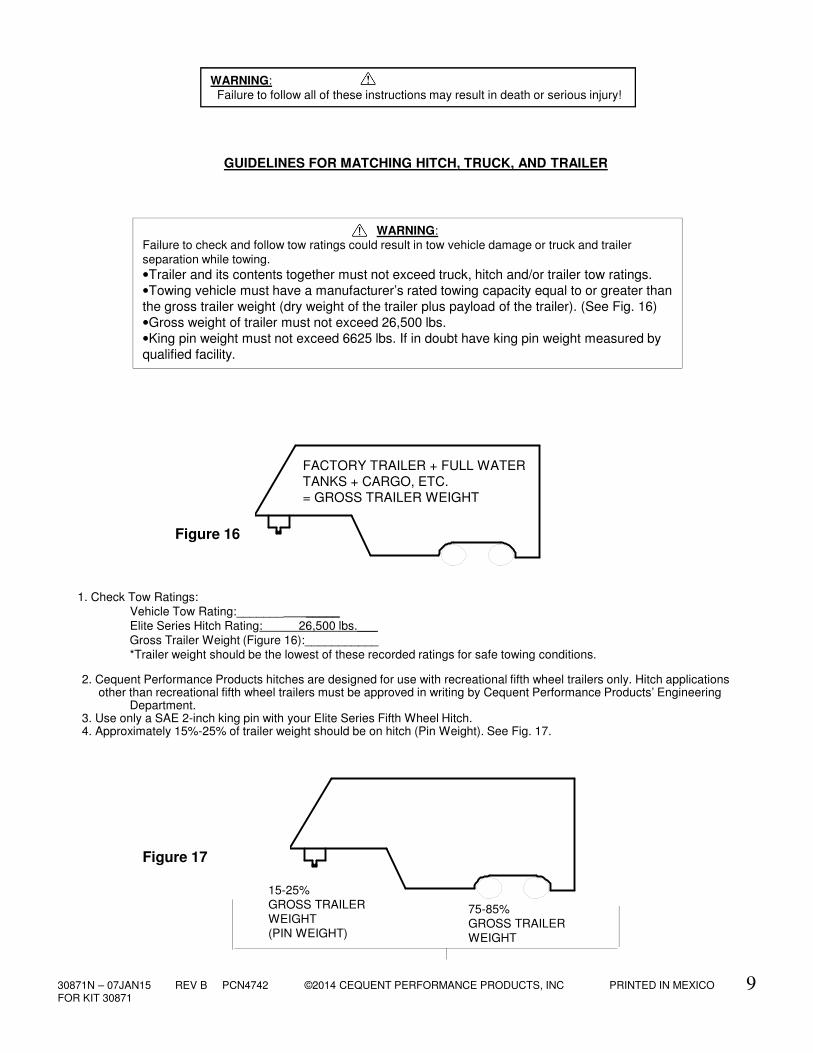
1. Check Tow Ratings: Vehicle Tow Rating:_______ _____
Elite Series Hitch Rating: 26,500 lbs.___ Gross Trailer Weight (Figure 16):___________*Trailer weight should be the lowest of these recorded ratings for safe towing conditions.
2. Cequent Performance Products hitches are designed for use with recreational fifth wheel trailers only. Hitch applicationsother than recreational fifth wheel trailers must be approved in writing by Cequent Performance Products’ Engineering
Department. 3. Use only a SAE 2-inch king pin with your Elite Series Fifth Wheel Hitch.4. Approximately 15%-25% of trailer weight should be on hitch (Pin Weight). See Fig. 17.
FACTORY TRAILER + FULL WATER
TANKS + CARGO, ETC.
= GROSS TRAILER WEIGHT
Figure 16
15-25%GROSS TRAILER
WEIGHT(PIN WEIGHT)
75-85%GROSS TRAILER WEIGHT
Figure 17
GUIDELINES FOR MATCHING HITCH, TRUCK, AND TRAILER
WARNING:Failure to follow all of these instructions may result in death or serious injury!
WARNING:Failure to check and follow tow ratings could result in tow vehicle damage or truck and trailer separation while towing.
•Trailer and its contents together must not exceed truck, hitch and/or trailer tow ratings.
•Towing vehicle must have a manufacturer’s rated towing capacity equal to or greater than
the gross trailer weight (dry weight of the trailer plus payload of the trailer). (See Fig. 16)
•Gross weight of trailer must not exceed 26,500 lbs.
•King pin weight must not exceed 6625 lbs. If in doubt have king pin weight measured by
qualified facility.
30871N – 07JAN15 REV B PCN4742 ©2014 CEQUENT PERFORMANCE PRODUCTS, INC PRINTED IN MEXICOFOR KIT 30871
10
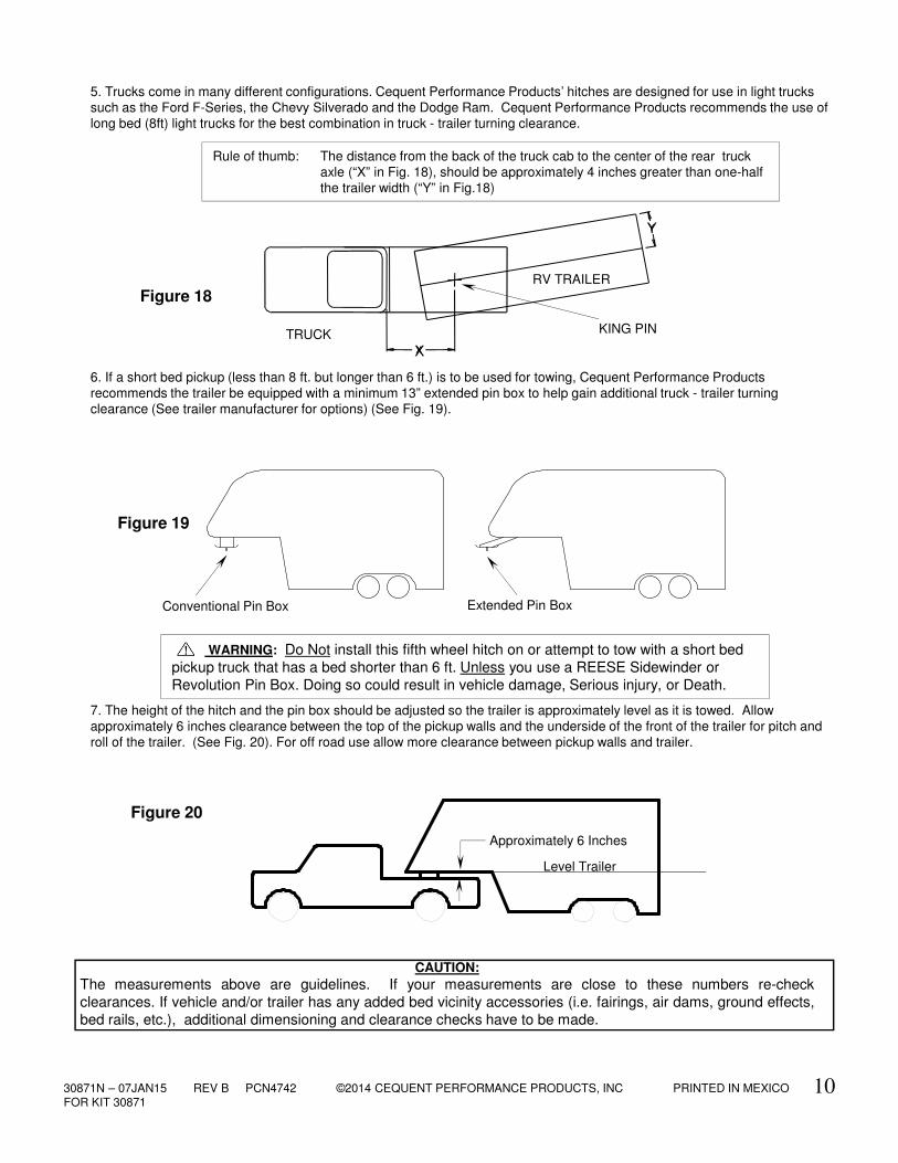
5. Trucks come in many different configurations. Cequent Performance Products’ hitches are designed for use in light trucks such as the Ford F-Series, the Chevy Silverado and the Dodge Ram. Cequent Performance Products recommends the use of long bed (8ft) light trucks for the best combination in truck - trailer turning clearance.
6. If a short bed pickup (less than 8 ft. but longer than 6 ft.) is to be used for towing, Cequent Performance Products recommends the trailer be equipped with a minimum 13” extended pin box to help gain additional truck - trailer turning clearance (See trailer manufacturer for options) (See Fig. 19).
7. The height of the hitch and the pin box should be adjusted so the trailer is approximately level as it is towed. Allowapproximately 6 inches clearance between the top of the pickup walls and the underside of the front of the trailer for pitch androll of the trailer. (See Fig. 20). For off road use allow more clearance between pickup walls and trailer.
KING PIN
RV TRAILER
TRUCK
Figure 18
Conventional Pin Box Extended Pin Box
Figure 19
Rule of thumb: The distance from the back of the truck cab to the center of the rear truck axle (“X” in Fig. 18), should be approximately 4 inches greater than one-half the trailer width (“Y” in Fig.18)
Approximately 6 Inches
Level Trailer
Figure 20
WARNING: Do Not install this fifth wheel hitch on or attempt to tow with a short bed
pickup truck that has a bed shorter than 6 ft. Unless you use a REESE Sidewinder or
Revolution Pin Box. Doing so could result in vehicle damage, Serious injury, or Death.
CAUTION:
The measurements above are guidelines. If your measurements are close to these numbers re-check
clearances. If vehicle and/or trailer has any added bed vicinity accessories (i.e. fairings, air dams, ground effects,
bed rails, etc.), additional dimensioning and clearance checks have to be made.
X
Y
30871N – 07JAN15 REV B PCN4742 ©2014 CEQUENT PERFORMANCE PRODUCTS, INC PRINTED IN MEXICOFOR KIT 30871
11
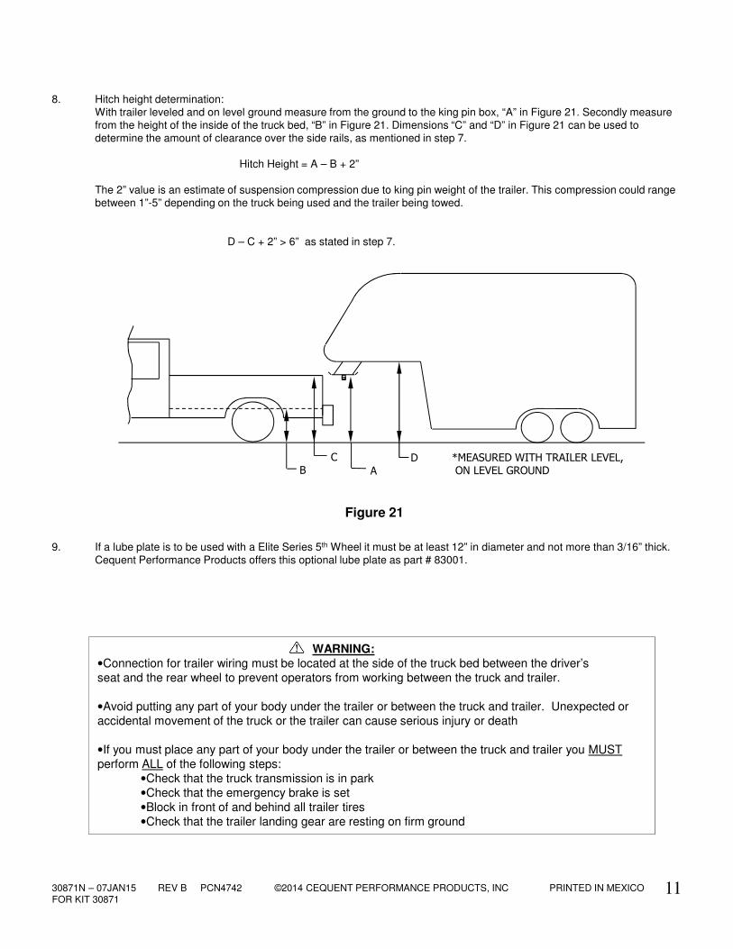
8. Hitch height determination:With trailer leveled and on level ground measure from the ground to the king pin box, “A” in Figure 21. Secondly measure from the height of the inside of the truck bed, “B” in Figure 21. Dimensions “C” and “D” in Figure 21 can be used to determine the amount of clearance over the side rails, as mentioned in step 7.
Hitch Height = A – B + 2”
The 2” value is an estimate of suspension compression due to king pin weight of the trailer. This compression could range between 1”-5” depending on the truck being used and the trailer being towed.
D – C + 2” > 6” as stated in step 7.
BDC
A
*MEASURED WITH TRAILER LEVEL,
ON LEVEL GROUND
WARNING:
•Connection for trailer wiring must be located at the side of the truck bed between the driver’s
seat and the rear wheel to prevent operators from working between the truck and trailer.
•Avoid putting any part of your body under the trailer or between the truck and trailer. Unexpected or
accidental movement of the truck or the trailer can cause serious injury or death
•If you must place any part of your body under the trailer or between the truck and trailer you MUST
perform ALL of the following steps:
•Check that the truck transmission is in park
•Check that the emergency brake is set
•Block in front of and behind all trailer tires
•Check that the trailer landing gear are resting on firm ground
9. If a lube plate is to be used with a Elite Series 5th Wheel it must be at least 12” in diameter and not more than 3/16” thick. Cequent Performance Products offers this optional lube plate as part # 83001.
Figure 21
30871N – 07JAN15 REV B PCN4742 ©2014 CEQUENT PERFORMANCE PRODUCTS, INC PRINTED IN MEXICOFOR KIT 30871
Figure 24
12
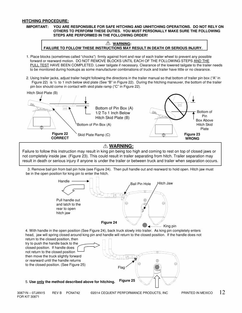
4. With handle in the open position (See Figure 24), back truck slowly into trailer. As king pin completely enters
head, jaw will spring closed around king pin and handle will return to the closed position. If the handle does not return to the closed position, then try to push the handle back to the closed position. If handle does not return to the closed position
then move the truck slightly forward or rearward until the handle returns to the closed position. (See Figure 25)
5. Use only the method described above for hitching.
WARNING:Failure to follow this instruction may result in king pin being too high and coming to rest on top of closed jaws or
not completely inside jaw. (Figure 23). This could result in trailer separating from hitch. Trailer separation may
result in death or serious injury if anyone is under the trailer or between truck and trailer when separation occurs.
3. Remove bail pin from bail pin hole (see Figure 24). Then pull handle out and rearward to hold open. Hitch jaw must be in the open position for king pin to enter the hitch.
King pin
Pull handle out and latch to the
rear to open hitch jaw
Hitch JawHandle
Bail Pin Hole
Figure 22CORRECT
Bottom of Pin Box (A)
1/2 To 1 Inch Below
Hitch Skid Plate (B)
Skid Plate Ramp (C)
Hitch Skid Plate (B)
Bottom of Pin Box (A)
IMPORTANT: YOU ARE RESPONSIBLE FOR SAFE HITCHING AND UNHITCHING OPERATIONS. DO NOT RELY ON OTHERS TO PERFORM THESE DUTIES. YOU MUST PERSONALLY MAKE SURE THE FOLLOWING STEPS ARE PERFORMED IN THE FOLLOWING ORDER!
WARNING:
FAILURE TO FOLLOW THESE INSTRUCTIONS MAY RESULT IN DEATH OR SERIOUS INJURY.
1. Place blocks (sometimes called “chocks”) firmly against front and rear of each trailer wheel to prevent any possible forward or rearward motion. DO NOT REMOVE BLOCKS UNTIL EACH OF THE FOLLOWING STEPS AND THE
PULL TEST HAVE BEEN COMPLETED. Lower tailgate if necessary. Clearance of the lowered tailgate to the trailer needs to be monitored during hookups as some manufacturer combinations of truck and trailer have little or no clearance.
2. Using trailer jacks, adjust trailer height following the directions in the trailer manual so that bottom of trailer pin box (“A” in Figure 22) is ½ to 1 inch below skid plate (See “B” in Figure 22). During the hitching maneuver, the bottom of the trailer
pin box should come in contact with skid plate ramp (“C” in Figure 22).
HITCHING PROCEDURE:
Bottom of Pin
Box AboveHitch Skid
Plate
Figure 23WRONG
Figure 25
Flag
30871N – 07JAN15 REV B PCN4742 ©2014 CEQUENT PERFORMANCE PRODUCTS, INC PRINTED IN MEXICOFOR KIT 30871
13
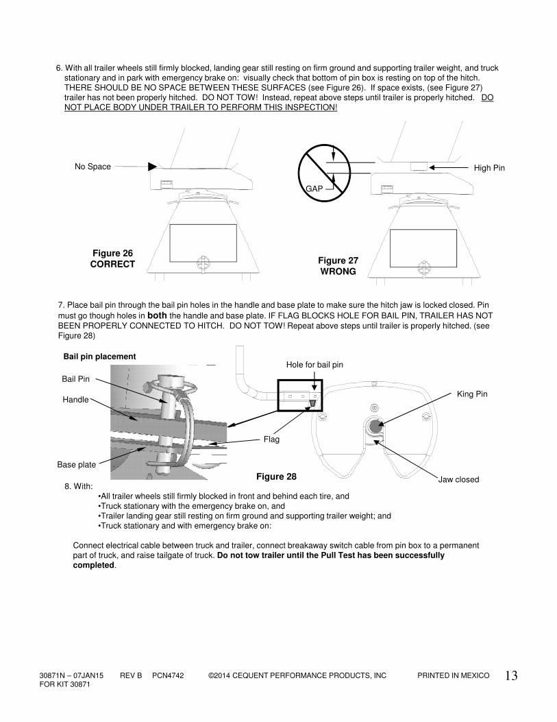
8. With:•All trailer wheels still firmly blocked in front and behind each tire, and•Truck stationary with the emergency brake on, and •Trailer landing gear still resting on firm ground and supporting trailer weight; and•Truck stationary and with emergency brake on:
Connect electrical cable between truck and trailer, connect breakaway switch cable from pin box to a permanent
part of truck, and raise tailgate of truck. Do not tow trailer until the Pull Test has been successfully completed.
7. Place bail pin through the bail pin holes in the handle and base plate to make sure the hitch jaw is locked closed. Pin
must go though holes in both the handle and base plate. IF FLAG BLOCKS HOLE FOR BAIL PIN, TRAILER HAS NOT
BEEN PROPERLY CONNECTED TO HITCH. DO NOT TOW! Repeat above steps until trailer is properly hitched. (see Figure 28)
6. With all trailer wheels still firmly blocked, landing gear still resting on firm ground and supporting trailer weight, and truck stationary and in park with emergency brake on: visually check that bottom of pin box is resting on top of the hitch. THERE SHOULD BE NO SPACE BETWEEN THESE SURFACES (see Figure 26). If space exists, (see Figure 27) trailer has not been properly hitched. DO NOT TOW! Instead, repeat above steps until trailer is properly hitched. DO NOT PLACE BODY UNDER TRAILER TO PERFORM THIS INSPECTION!
Figure 27
WRONG
Figure 26
CORRECT
High PinNo Space
GAP
King Pin
Jaw closedFigure 28
Hole for bail pin
Flag
Handle
Base plate
Bail pin placement
Bail Pin
30871N – 07JAN15 REV B PCN4742 ©2014 CEQUENT PERFORMANCE PRODUCTS, INC PRINTED IN MEXICOFOR KIT 30871
14
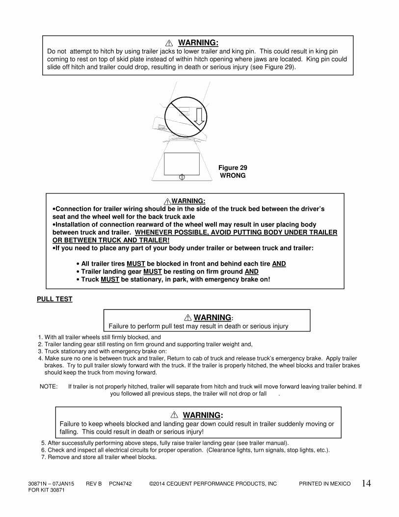
WARNING:Do not attempt to hitch by using trailer jacks to lower trailer and king pin. This could result in king pin
coming to rest on top of skid plate instead of within hitch opening where jaws are located. King pin could
slide off hitch and trailer could drop, resulting in death or serious injury (see Figure 29).
1. With all trailer wheels still firmly blocked, and
2. Trailer landing gear still resting on firm ground and supporting trailer weight and,3. Truck stationary and with emergency brake on:
4. Make sure no one is between truck and trailer, Return to cab of truck and release truck’s emergency brake. Apply trailer brakes. Try to pull trailer slowly forward with the truck. If the trailer is properly hitched, the wheel blocks and trailer brakes should keep the truck from moving forward.
NOTE: If trailer is not properly hitched, trailer will separate from hitch and truck will move forward leaving trailer behind. If
you followed all previous steps, the trailer will not drop or fall .
5. After successfully performing above steps, fully raise trailer landing gear (see trailer manual).6. Check and inspect all electrical circuits for proper operation. (Clearance lights, turn signals, stop lights, etc.).
7. Remove and store all trailer wheel blocks.
PULL TEST
WARNING:Failure to keep wheels blocked and landing gear down could result in trailer suddenly moving or
falling. This could result in death or serious injury!
WARNING:
Failure to perform pull test may result in death or serious injury
WARNING:
•Connection for trailer wiring should be in the side of the truck bed between the driver’s
seat and the wheel well for the back truck axle
•Installation of connection rearward of the wheel well may result in user placing body
between truck and trailer. WHENEVER POSSIBLE, AVOID PUTTING BODY UNDER TRAILER
OR BETWEEN TRUCK AND TRAILER!
•If you need to place any part of your body under trailer or between truck and trailer:
• All trailer tires MUST be blocked in front and behind each tire AND
• Trailer landing gear MUST be resting on firm ground AND
• Truck MUST be stationary, in park, with emergency brake on!
Figure 29
WRONG
30871N – 07JAN15 REV B PCN4742 ©2014 CEQUENT PERFORMANCE PRODUCTS, INC PRINTED IN MEXICOFOR KIT 30871
15
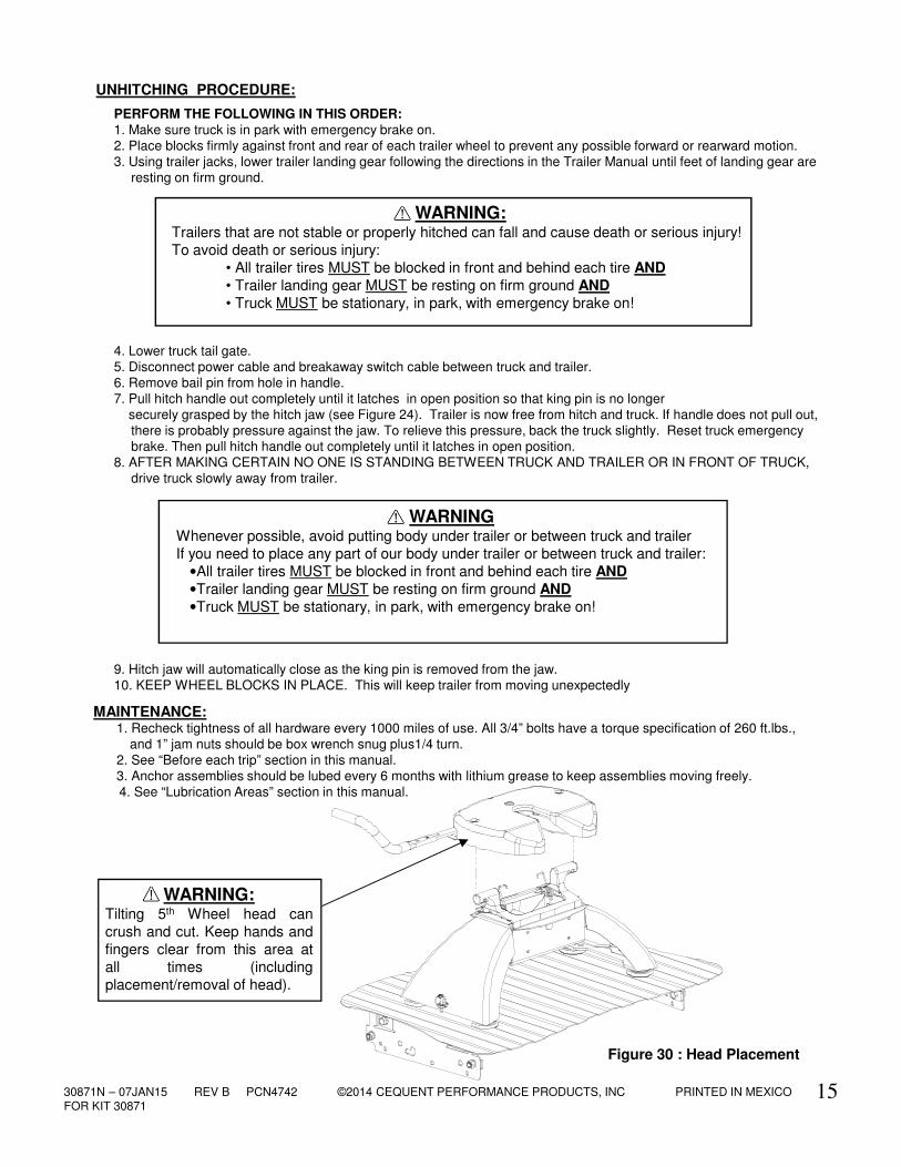
PERFORM THE FOLLOWING IN THIS ORDER:1. Make sure truck is in park with emergency brake on.2. Place blocks firmly against front and rear of each trailer wheel to prevent any possible forward or rearward motion.3. Using trailer jacks, lower trailer landing gear following the directions in the Trailer Manual until feet of landing gear are
resting on firm ground.
4. Lower truck tail gate.5. Disconnect power cable and breakaway switch cable between truck and trailer.6. Remove bail pin from hole in handle. 7. Pull hitch handle out completely until it latches in open position so that king pin is no longer
securely grasped by the hitch jaw (see Figure 24). Trailer is now free from hitch and truck. If handle does not pull out, there is probably pressure against the jaw. To relieve this pressure, back the truck slightly. Reset truck emergency brake. Then pull hitch handle out completely until it latches in open position.
8. AFTER MAKING CERTAIN NO ONE IS STANDING BETWEEN TRUCK AND TRAILER OR IN FRONT OF TRUCK, drive truck slowly away from trailer.
9. Hitch jaw will automatically close as the king pin is removed from the jaw. 10. KEEP WHEEL BLOCKS IN PLACE. This will keep trailer from moving unexpectedly
1. Recheck tightness of all hardware every 1000 miles of use. All 3/4” bolts have a torque specification of 260 ft.lbs., and 1” jam nuts should be box wrench snug plus1/4 turn.
2. See “Before each trip” section in this manual.3. Anchor assemblies should be lubed every 6 months with lithium grease to keep assemblies moving freely.4. See “Lubrication Areas” section in this manual.
MAINTENANCE:
WARNINGWhenever possible, avoid putting body under trailer or between truck and trailer
If you need to place any part of our body under trailer or between truck and trailer:
•All trailer tires MUST be blocked in front and behind each tire AND
•Trailer landing gear MUST be resting on firm ground AND
•Truck MUST be stationary, in park, with emergency brake on!
UNHITCHING PROCEDURE:
WARNING:Trailers that are not stable or properly hitched can fall and cause death or serious injury!
To avoid death or serious injury:
• All trailer tires MUST be blocked in front and behind each tire AND
• Trailer landing gear MUST be resting on firm ground AND
• Truck MUST be stationary, in park, with emergency brake on!
Figure 30 : Head Placement
WARNING:Tilting 5th Wheel head can
crush and cut. Keep hands and
fingers clear from this area at
all times (including
placement/removal of head).
30871N – 07JAN15 REV B PCN4742 ©2014 CEQUENT PERFORMANCE PRODUCTS, INC PRINTED IN MEXICOFOR KIT 30871
16
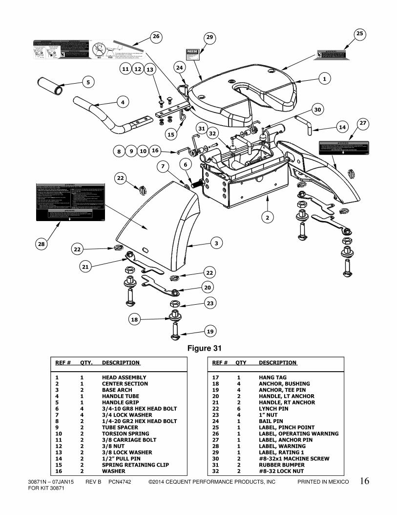
REF # QTY. DESCRIPTION
1 1 HEAD ASSEMBLY 2 1 CENTER SECTION3 2 BASE ARCH4 1 HANDLE TUBE5 1 HANDLE GRIP6 4 3/4-10 GR8 HEX HEAD BOLT7 4 3/4 LOCK WASHER8 2 1/4-20 GR2 HEX HEAD BOLT 9 2 TUBE SPACER10 2 TORSION SPRING11 2 3/8 CARRIAGE BOLT12 2 3/8 NUT13 2 3/8 LOCK WASHER14 2 1/2” PULL PIN15 2 SPRING RETAINING CLIP16 2 WASHER
REF # QTY DESCRIPTION
17 1 HANG TAG18 4 ANCHOR, BUSHING19 4 ANCHOR, TEE PIN20 2 HANDLE, LT ANCHOR21 2 HANDLE, RT ANCHOR22 6 LYNCH PIN23 4 1” NUT24 1 BAIL PIN25 1 LABEL, PINCH POINT26 1 LABEL, OPERATING WARNING27 1 LABEL, ANCHOR PIN28 1 LABEL, WARNING29 1 LABEL, RATING 130 2 #8-32x1 MACHINE SCREW31 2 RUBBER BUMPER32 2 #8-32 LOCK NUT
Figure 31
2625
28
27
29
22
21
23
18
20
19
22
7
2
4
6
5
14
30
3
1
1531
22
8 9 10 16
131211
32
24
30871N – 07JAN15 REV B PCN4742 ©2014 CEQUENT PERFORMANCE PRODUCTS, INC PRINTED IN MEXICOFOR KIT 30871
17
NOTES
LIMITED LIFETIME WARRANTY
Hitches - Custom Receivers
Cequent Performance Products Inc. (“We” or “Us”) warrants to the original consumer purchaser only
(“You”) that the product will be free from material defects in both material and workmanship, ordinary wear
and tear expected; provided that installation and use of the product is in accordance with product
instructions. There are no other warranties, express or implied, including the warranty of merchantability
or fitness for a particular purpose. This warranty is not transferable.
This warranty does not cover: (a) normal wear and tear; (b) damage through abuse, neglect, misuse, or as
a result of any accident or in any other manner; (c) damage from misapplication, overloading, or improper
installation; (d) improper maintenance and repair; and (e) product alteration in any manner by anyone
other than Us, with the sole exception of alterations made pursuant to product instructions and in a
workmanlike manner.
To make a Warranty claim, contact Us, at our principal address of 47912 Halyard Dr. Suite 100, Plymouth,
MI 48170, 1-800-632-3290, identify the product by model number, and follow the claim instructions that
will be provided. Any returned product that is replaced by Us becomes our property. You will be
responsible for return shipping costs. Please retain your purchase receipt to verify date of purchase and
that You are the original consumer purchaser. The product and the purchase receipt must be provided to
Us in order to process Your Warranty claim.
Product replacement is Your sole remedy under this Warranty. We shall not be liable for service or labor
charges incurred in removing or replacing a product or any incidental or consequential damages of any
kind.
You acknowledge and agree that any use of the product for any purpose other than the specified use(s)
stated in the product instructions is at Your own risk.
This Warranty gives you specific legal rights, and You may also have other rights which vary from state to
state. This Warranty is governed by the laws of the State of Michigan, without regard to rules pertaining to
conflicts of law. The state courts located in Oakland County, Michigan shall have exclusive jurisdiction for
any disputes relating to this warranty.
Cequent Performance Products, Inc.
47912 Halyard Dr. Suite 100
Plymouth, MI 48170