on the right track installation...
TRANSCRIPT
On the Right Track
Installation Guide
General Introduction Introduction...................................................................1 Local Building Codes......................................................1 Tools Required...............................................................1 Additional Assistance....................................................1
Parts Glossary Components...................................................................2 Track..............................................................................5
Installation - CeilingPlease select ceiling type and proceed to page 14
Installing into ACT 15/16” Exposed Grid.......................7 Installing into ACT 9/16” Exposed Grid with Recessed Tiles........................................................8 Installing into Traditional Cubicle Curtain Track.............9 Installing into Gypsum Board Ceilings............................10 Installing into Plywood Ceilings......................................11 Installing into Concrete or Masonry Ceilings.................12 InstallingintoaWall/Soffit.............................................13
Installation - Components Parts Assembly.............................................................14 Connecting the Track Connector..................................15 Connecting the Hanger & Track Connector..................16 Connecting the End Cap...............................................17 Connecting the End Wall Plate......................................18 Installing Rail Drops.......................................................19 Installing Ceiling Blocking..............................................20
Appendix Graphical Track Layout.................................................21 Graphical Track Layout with Drops...............................22 GraphicalCeilingInstallation..........................................23 Installation and Building Code for Concrete Anchor......25
Maintenance..............................................................33
Table of Contents

Introduction
On The Right Track’s worldwide patented cubicle curtain system includes a state-of-the-art track system that will give you years of ageless beauty and
carefree enjoyment.
The following illustrated instructions have been provided to help you understand and take advantage of various scenarios and their appropriate
installation techniques. Following these instructions along with good building practices will deliver the highest quality installation. Failure to follow these
instructions also risks voiding the OTRT warranty.
Local Building CodesPlease follow all building codes and good construction practices when installing the curtain track. In addition to local codes, be sure to follow the instructions
in this guide. Failure to do so may void your OTRT warranty.
Tools required
Rubber malletPhillips screwdriver
Chop Saw with a non-ferrous aluminum blade or Hand SawFile
Laser LevelMeasuring Tape
TE-CX 1/4” x 6” Hammer drill bit (for concrete anchors only)HILTI 7/16” Drive Socket ( for concrete anchors only)
Additional Assistance
For additional assistance, be sure to view our installation videos at:www.ontherighttrack.com/installers-resources
PatentNo.:USD669,721S;5,186,232;6,494,248;6,935,402;7,296,609CN100384356C;UK2,458,075andotherUS/int’lpatentspending.
1
General Introduction
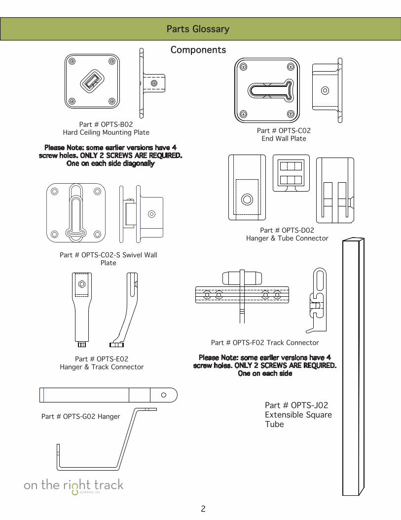
Please Note: some earlier versions have 4 screw holes. ONLY 2 SCREWS ARE REQUIRED.
One on each side
Part # OPTS-F02 Track Connector
Part # OPTS-B02Hard Ceiling Mounting Plate
Please Note: some earlier versions have 4 screw holes. ONLY 2 SCREWS ARE REQUIRED.
One on each side diagonally
Part # OPTS-G02 Hanger
Part # OPTS-C02End Wall Plate
Part # OPTS-E02Hanger & Track Connector
Part # OPTS-C02-S Swivel Wall Plate
Part # OPTS-D02Hanger & Tube Connector
Part # OPTS-J02Extensible Square Tube
2
Parts Glossary
Components
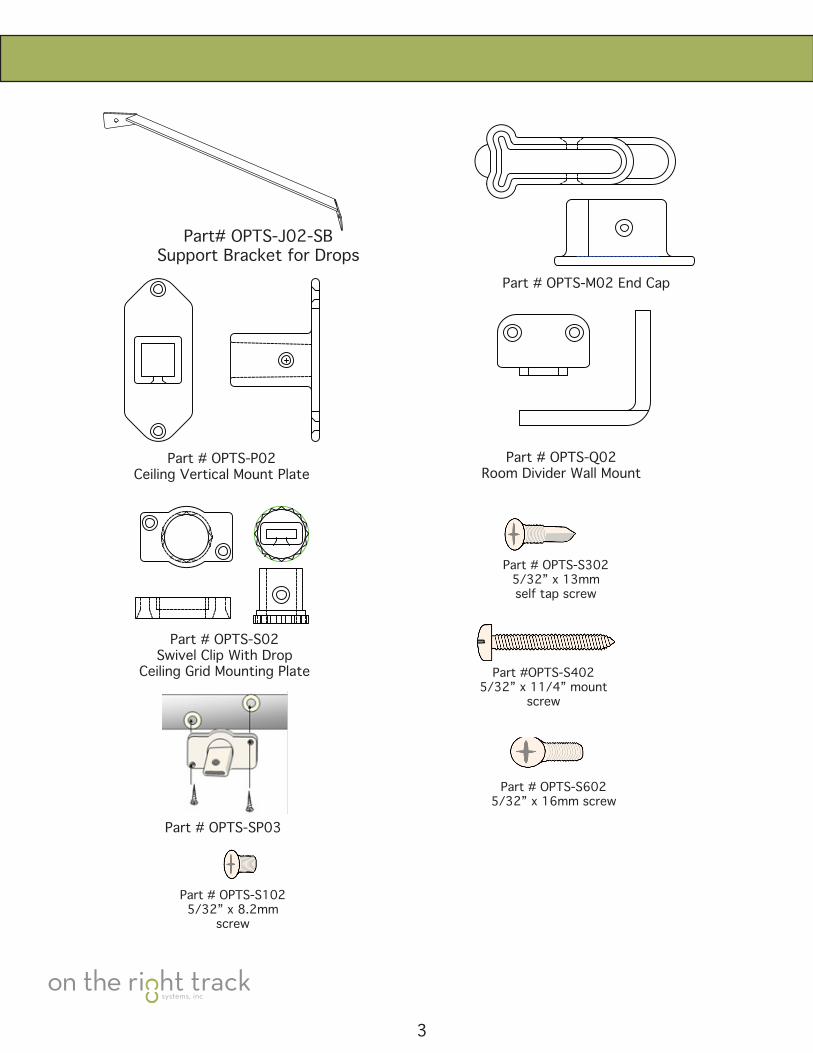
Part # OPTS-M02 End Cap
Part # OPTS-S02Swivel Clip With Drop
Ceiling Grid Mounting Plate
Part # OPTS-Q02Room Divider Wall Mount
Part # OPTS-P02Ceiling Vertical Mount Plate
Part#OPTS-SP03
Part # OPTS-S1025/32”x8.2mm
screw
Part # OPTS-S6025/32”x16mmscrew
Part#OPTS-S3025/32”x13mmself tap screw
Part #OPTS-S4025/32”x11/4”mount
screw
3
Part# OPTS-J02-SBSupport Bracket for Drops
4
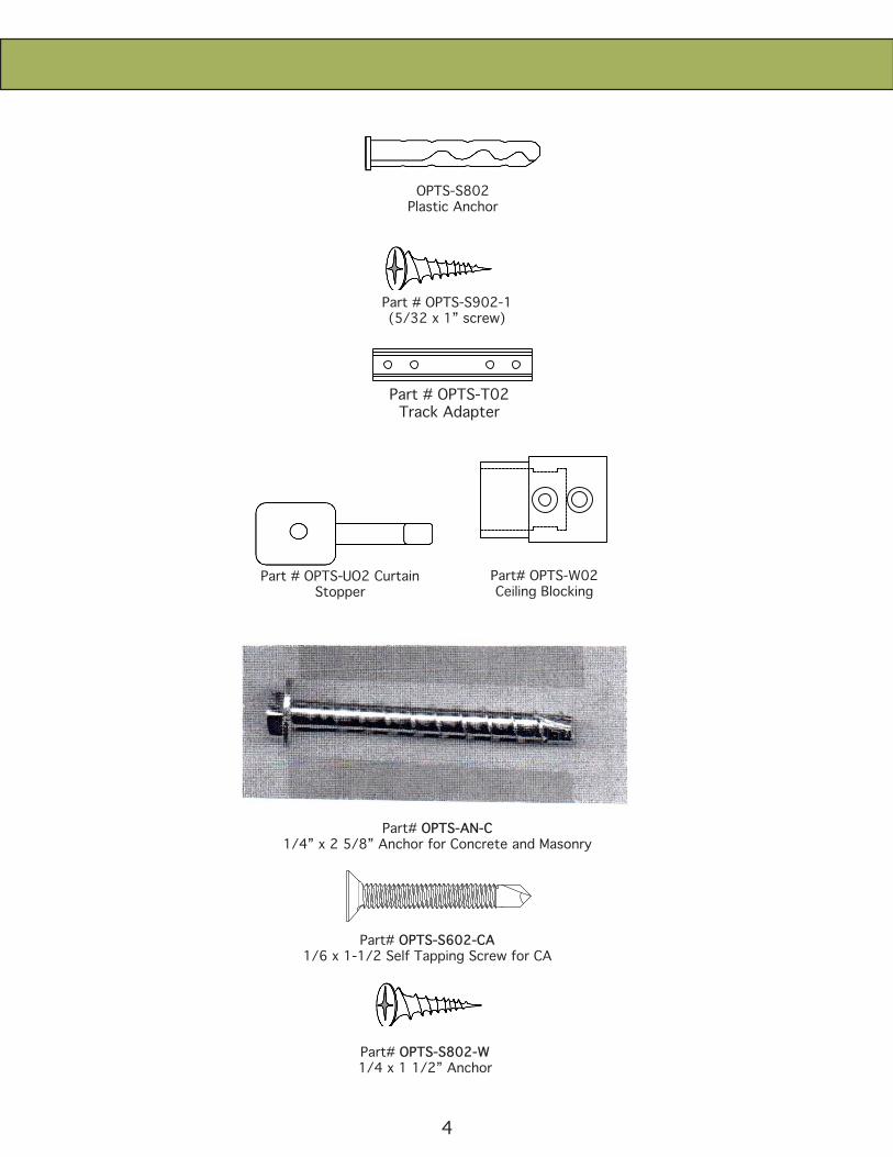
Part# OPTS-S602-CA1/6 x 1-1/2 Self Tapping Screw for CA
Part# OPTS-S802-W1/4 x 1 1/2” Anchor
Part# OPTS-AN-C1/4” x 2 5/8” Anchor for Concrete and Masonry
Part # OPTS-UO2 CurtainStopper
Part# OPTS-W02Ceiling Blocking
Part # OPTS-T02Track Adapter
OPTS-S802Plastic Anchor
Part # OPTS-S902-1 (5/32x1”screw)
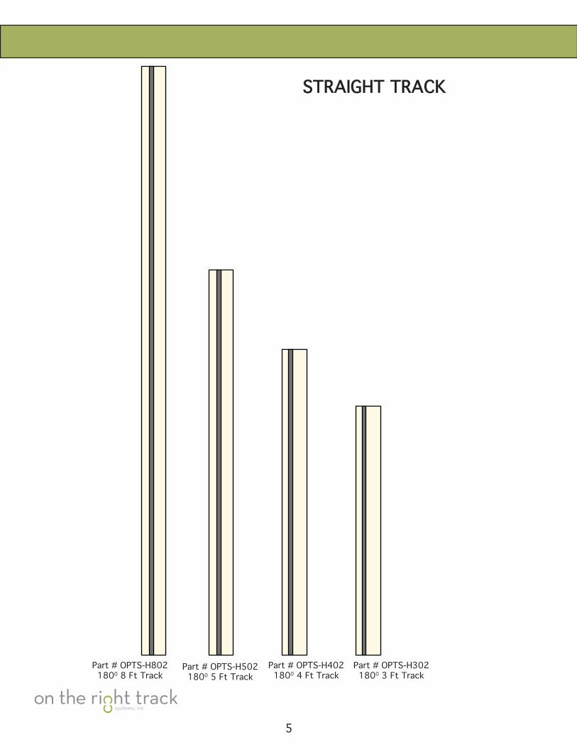
Part # OPTS-H8021800 8 Ft Track
Part # OPTS-H5021800 5 Ft Track
Part # OPTS-H4021800 4 Ft Track
Part#OPTS-H30218003FtTrack
STRAIGHT TRACK
5
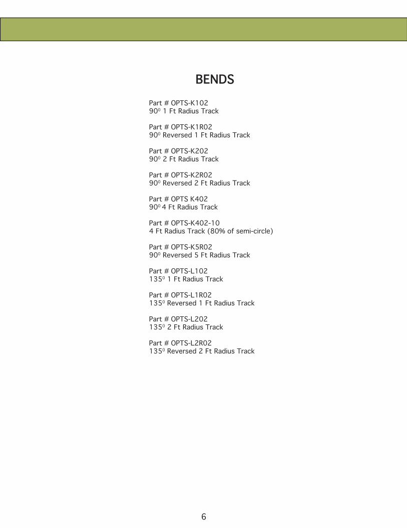
Part#OPTS-K102900 1 Ft Radius Track
Part#OPTS-K1R02900 Reversed 1 Ft Radius Track
Part#OPTS-K202900 2 Ft Radius Track
Part#OPTS-K2R02900 Reversed 2 Ft Radius Track
Part#OPTSK402900 4 Ft Radius Track
Part#OPTS-K402-104 Ft Radius Track (80% of semi-circle)
Part#OPTS-K5R02900 Reversed 5 Ft Radius Track
Part # OPTS-L1021350 1 Ft Radius Track
Part # OPTS-L1R021350 Reversed 1 Ft Radius Track
Part # OPTS-L2021350 2 Ft Radius Track
Part # OPTS-L2R021350 Reversed 2 Ft Radius Track
6
BENDS
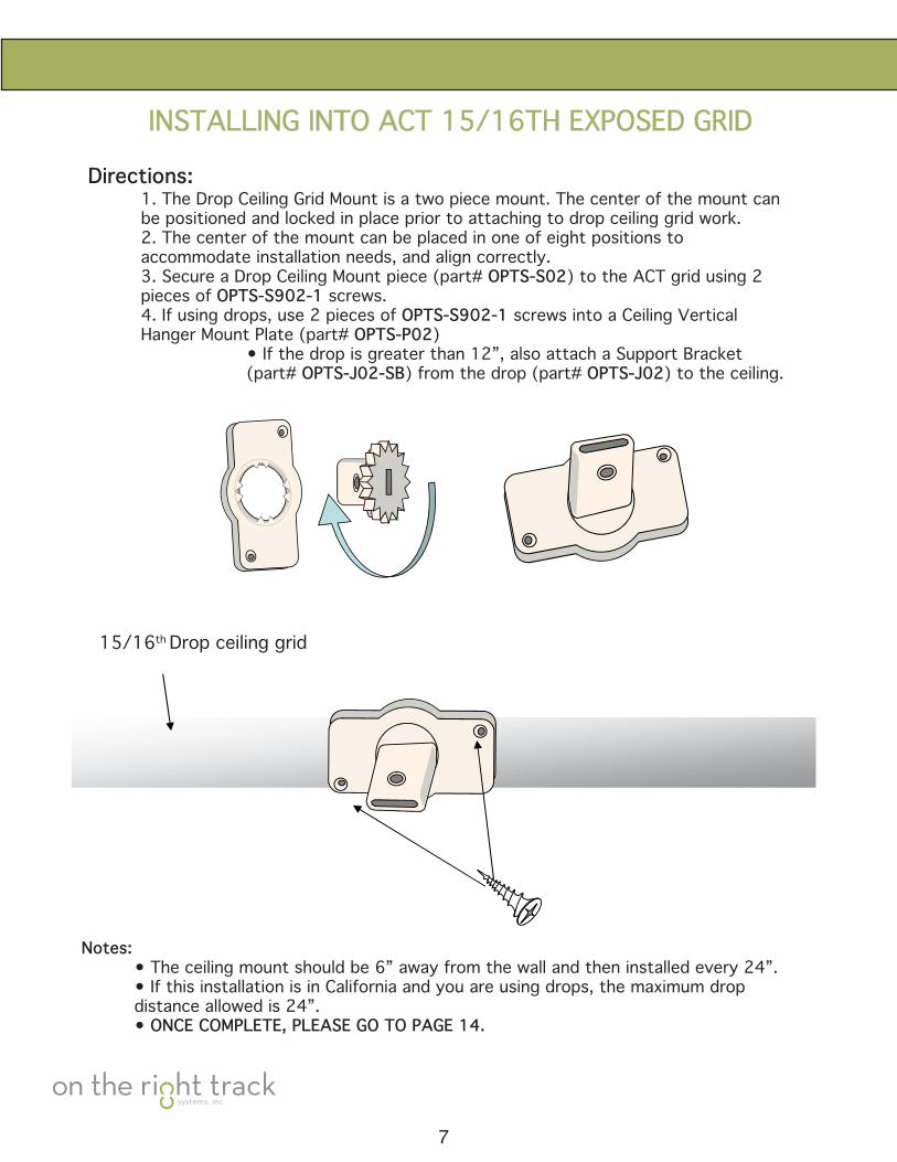
INSTALLING INTO ACT 15/16TH EXPOSED GRID
Directions: 1. The Drop Ceiling Grid Mount is a two piece mount. The center of the mount can be positioned and locked in place prior to attaching to drop ceiling grid work. 2. The center of the mount can be placed in one of eight positions to accommodate installation needs, and align correctly. 3.SecureaDropCeilingMountpiece(part#OPTS-S02) to the ACT grid using 2 pieces of OPTS-S902-1 screws. 4. If using drops, use 2 pieces of OPTS-S902-1 screws into a Ceiling Vertical Hanger Mount Plate (part# OPTS-P02) • If the drop is greater than 12”, also attach a Support Bracket (part# OPTS-J02-SB) from the drop (part# OPTS-J02) to the ceiling.
15/16th Drop ceiling grid
Notes: • The ceiling mount should be 6” away from the wall and then installed every 24”. • If this installation is in California and you are using drops, the maximum drop distance allowed is 24”. • ONCE COMPLETE, PLEASE GO TO PAGE 14.
7
INSTALLING INTO ACT 9/16” EXPOSED GRID WITH RECESSED TILES
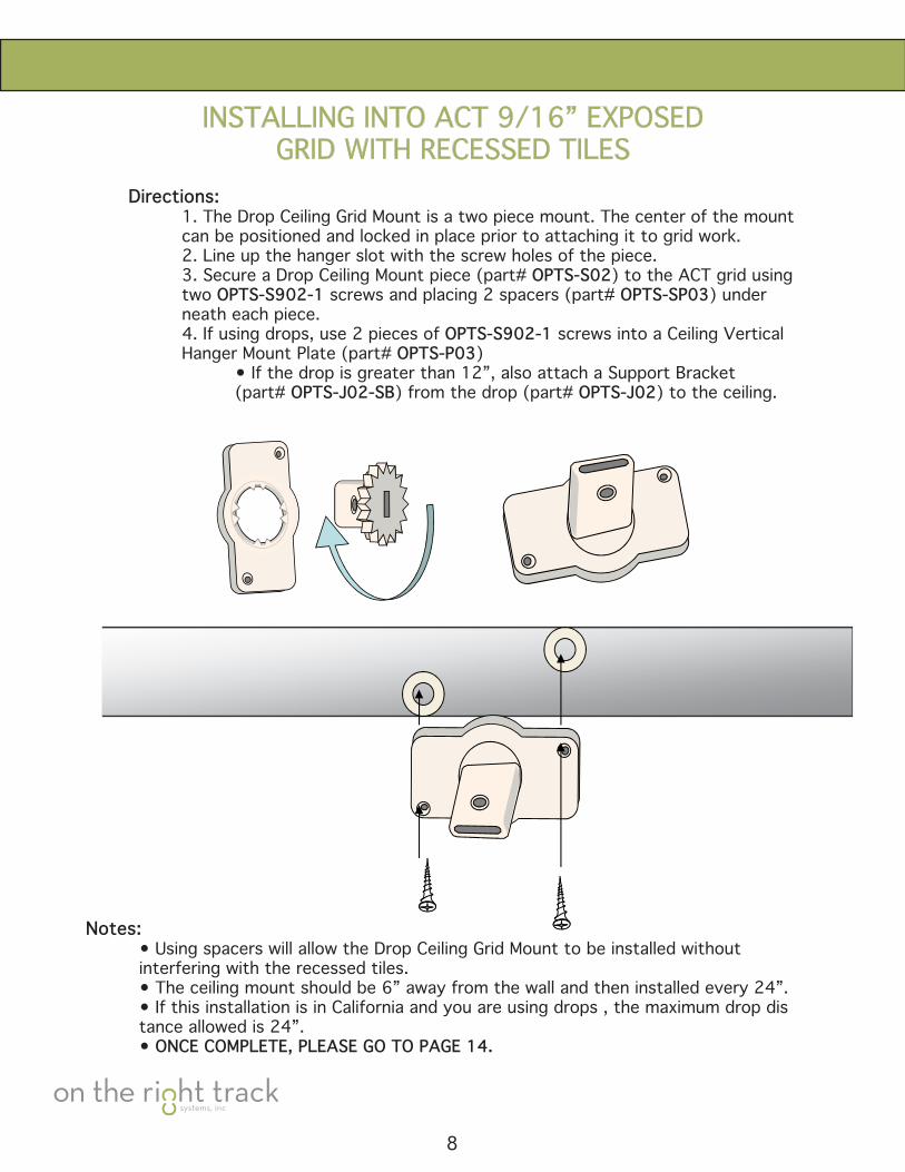
Directions: 1. The Drop Ceiling Grid Mount is a two piece mount. The center of the mount can be positioned and locked in place prior to attaching it to grid work. 2. Line up the hanger slot with the screw holes of the piece. 3.SecureaDropCeilingMountpiece(part#OPTS-S02) to the ACT grid using two OPTS-S902-1 screws and placing 2 spacers (part# OPTS-SP03) under neath each piece. 4. If using drops, use 2 pieces of OPTS-S902-1 screws into a Ceiling Vertical Hanger Mount Plate (part# OPTS-P03) • If the drop is greater than 12”, also attach a Support Bracket (part# OPTS-J02-SB) from the drop (part# OPTS-J02) to the ceiling.
Notes: • Using spacers will allow the Drop Ceiling Grid Mount to be installed without interfering with the recessed tiles. • The ceiling mount should be 6” away from the wall and then installed every 24”. • If this installation is in California and you are using drops , the maximum drop dis tance allowed is 24”. • ONCE COMPLETE, PLEASE GO TO PAGE 14.
8
INSTALLING INTO TRADITIONALCUBICLECURTAINTRACK
9
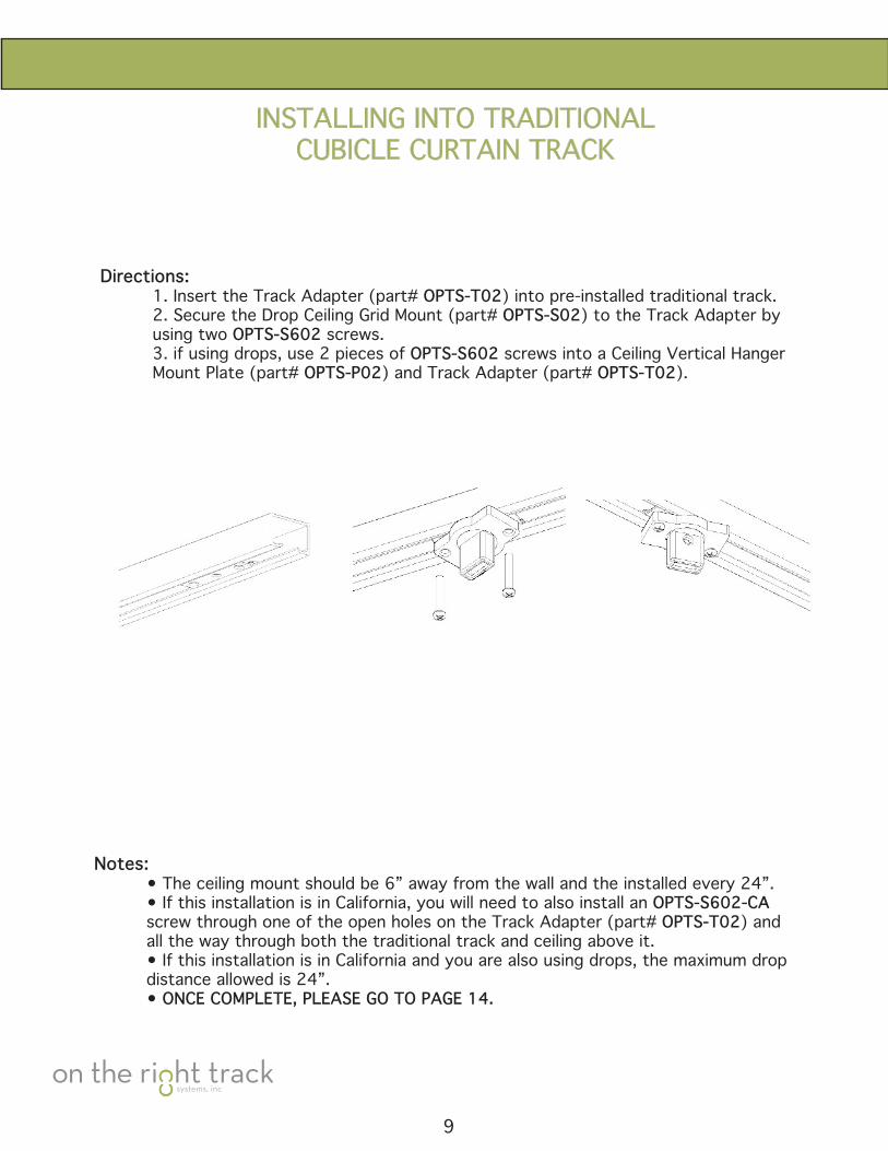
Directions: 1. Insert the Track Adapter (part# OPTS-T02) into pre-installed traditional track. 2. Secure the Drop Ceiling Grid Mount (part# OPTS-S02) to the Track Adapter by using two OPTS-S602 screws. 3.ifusingdrops,use2piecesofOPTS-S602 screws into a Ceiling Vertical Hanger Mount Plate (part# OPTS-P02) and Track Adapter (part# OPTS-T02).
Notes: • The ceiling mount should be 6” away from the wall and the installed every 24”. • If this installation is in California, you will need to also install an OPTS-S602-CA screw through one of the open holes on the Track Adapter (part# OPTS-T02) and all the way through both the traditional track and ceiling above it. • If this installation is in California and you are also using drops, the maximum drop distance allowed is 24”. • ONCE COMPLETE, PLEASE GO TO PAGE 14.
INSTALLING INTO GYPSUM BOARD CEILINGS
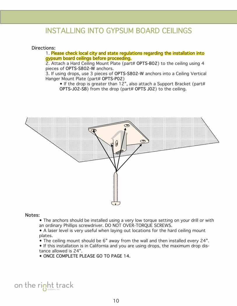
Directions: 1. Please check local city and state regulations regarding the installation into gypsum board ceilings before proceeding. 2. Attach a Hard Ceiling Mount Plate (part# OPTS-B02) to the ceiling using 4 pieces of OPTS-S802-W anchors. 3.Ifusingdrops,use3piecesofOPTS-S802-W anchors into a Ceiling Vertical Hanger Mount Plate (part# OPTS-P02) • If the drop is greater than 12”, also attach a Support Bracket (part# OPTS-J02-SB) from the drop (part# OPTS J02) to the ceiling.
Notes: • The anchors should be installed using a very low torque setting on your drill or with an ordinary Phillips screwdriver. DO NOT OVER-TORQUE SCREWS. • A laser level is very useful when laying out locations for the hard ceiling mount plates. • The ceiling mount should be 6” away from the wall and then installed every 24”. • If this installation is in California and you are using drops, the maximum drop dis- tance allowed is 24”. • ONCE COMPLETE PLEASE GO TO PAGE 14.
10
INSTALLING INTO PLYWOOD CEILINGS
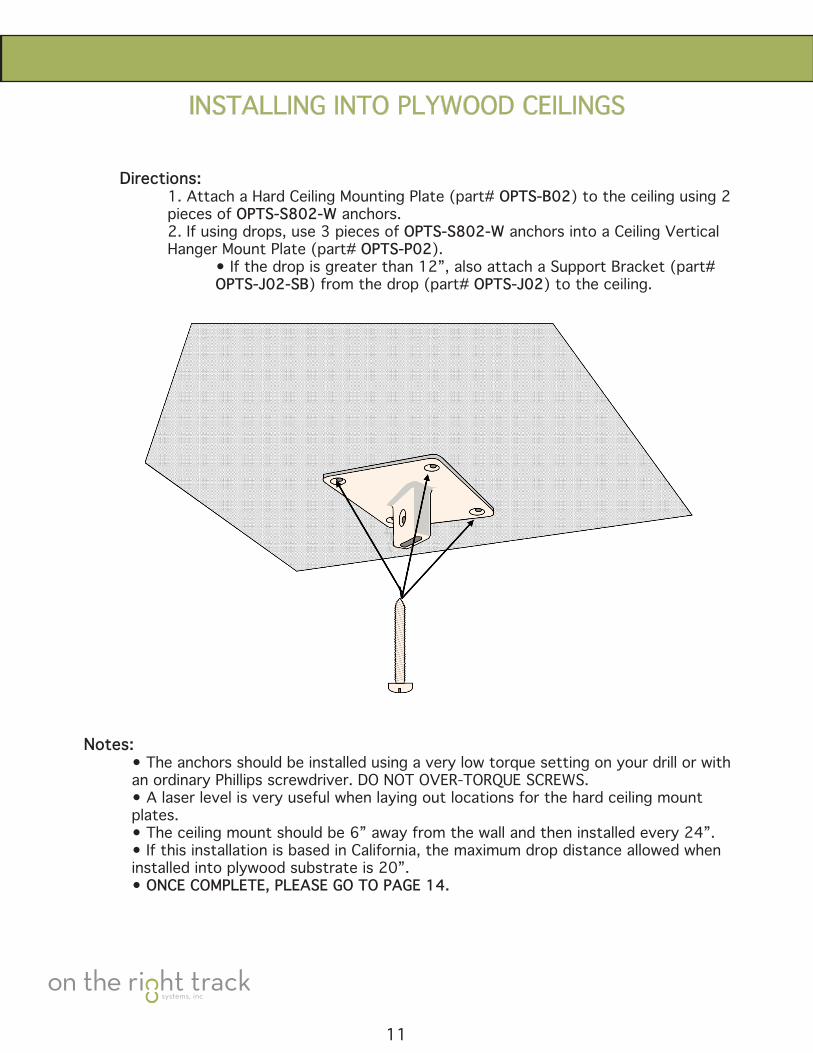
Directions: 1. Attach a Hard Ceiling Mounting Plate (part# OPTS-B02) to the ceiling using 2 pieces of OPTS-S802-W anchors. 2.Ifusingdrops,use3piecesofOPTS-S802-W anchors into a Ceiling Vertical Hanger Mount Plate (part# OPTS-P02). • If the drop is greater than 12”, also attach a Support Bracket (part# OPTS-J02-SB) from the drop (part# OPTS-J02) to the ceiling.
Notes: • The anchors should be installed using a very low torque setting on your drill or with an ordinary Phillips screwdriver. DO NOT OVER-TORQUE SCREWS. • A laser level is very useful when laying out locations for the hard ceiling mount plates. • The ceiling mount should be 6” away from the wall and then installed every 24”. • If this installation is based in California, the maximum drop distance allowed when installed into plywood substrate is 20”. • ONCE COMPLETE, PLEASE GO TO PAGE 14.
11
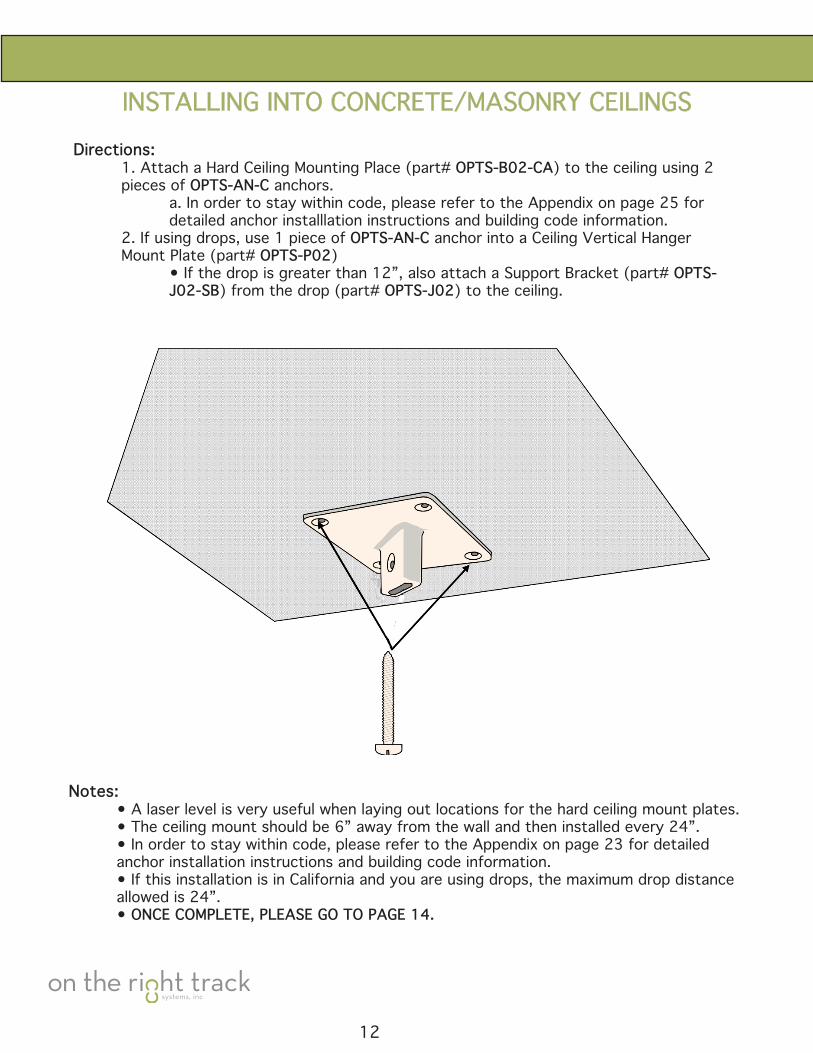
INSTALLING INTO CONCRETE/MASONRY CEILINGSDirections: 1. Attach a Hard Ceiling Mounting Place (part# OPTS-B02-CA) to the ceiling using 2 pieces of OPTS-AN-C anchors. a. In order to stay within code, please refer to the Appendix on page 25 for detailed anchor installlation instructions and building code information. 2. If using drops, use 1 piece of OPTS-AN-C anchor into a Ceiling Vertical Hanger Mount Plate (part# OPTS-P02) • If the drop is greater than 12”, also attach a Support Bracket (part# OPTS- J02-SB) from the drop (part# OPTS-J02) to the ceiling.
Notes: • A laser level is very useful when laying out locations for the hard ceiling mount plates. • The ceiling mount should be 6” away from the wall and then installed every 24”. •Inordertostaywithincode,pleaserefertotheAppendixonpage23fordetailed anchor installation instructions and building code information. • If this installation is in California and you are using drops, the maximum drop distance allowed is 24”. • ONCE COMPLETE, PLEASE GO TO PAGE 14.
12
INSTALLING INTO A WALL/SOFFIT
13
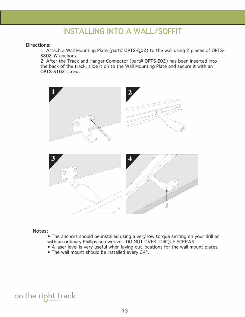
Directions: 1. Attach a Wall Mounting Plate (part# OPTS-Q02) to the wall using 2 pieces of OPTS- S802-W anchors. 2. After the Track and Hanger Connector (part# OPTS-E02) has been inserted into the back of the track, slide it on to the Wall Mounting Plate and secure it with an OPTS-S102 screw.
Notes: • The anchors should be installed using a very low torque setting on your drill or with an ordinary Phillips screwdriver. DO NOT OVER-TORQUE SCREWS. • A laser level is very useful when laying out locations for the wall mount plates. • The wall mount should be installed every 24”.
PARTS ASSEMBLY
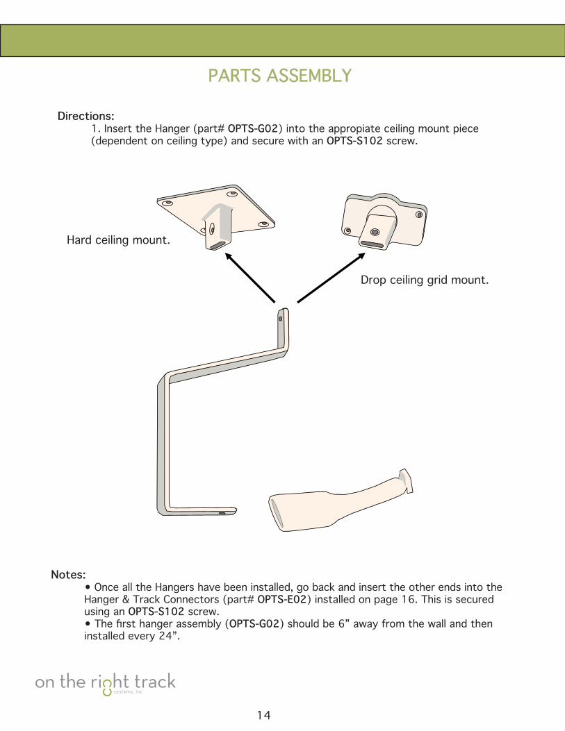
Directions: 1. Insert the Hanger (part# OPTS-G02) into the appropiate ceiling mount piece (dependent on ceiling type) and secure with an OPTS-S102 screw.
Hard ceiling mount.
Drop ceiling grid mount.
Notes: • Once all the Hangers have been installed, go back and insert the other ends into the Hanger & Track Connectors (part# OPTS-E02) installed on page 16. This is secured using an OPTS-S102 screw. •Thefirsthangerassembly(OPTS-G02) should be 6” away from the wall and then installed every 24”.
14
.
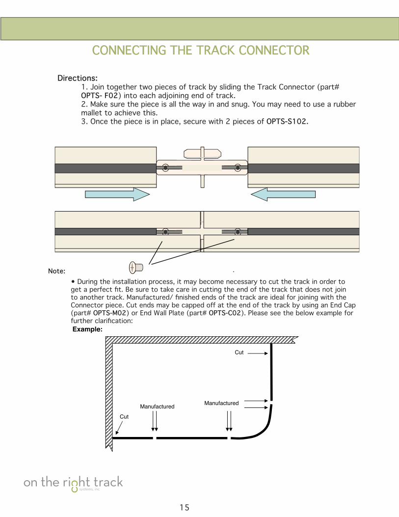
Example:
Cut
Manufactured
Cut
Manufactured
.
CONNECTINGTHETRACKCONNECTOR
Directions: 1. Join together two pieces of track by sliding the Track Connector (part# OPTS- F02) into each adjoining end of track. 2. Make sure the piece is all the way in and snug. You may need to use a rubber mallet to achieve this. 3.Oncethepieceisinplace,securewith2piecesofOPTS-S102.
• During the installation process, it may become necessary to cut the track in order to getaperfectfit.Besuretotakecareincuttingtheendofthetrackthatdoesnotjointoanothertrack.Manufactured/finishedendsofthetrackareidealforjoiningwiththeConnector piece. Cut ends may be capped off at the end of the track by using an End Cap (part# OPTS-M02) or End Wall Plate (part# OPTS-C02). Please see the below example for furtherclarification:
15
Note:
16
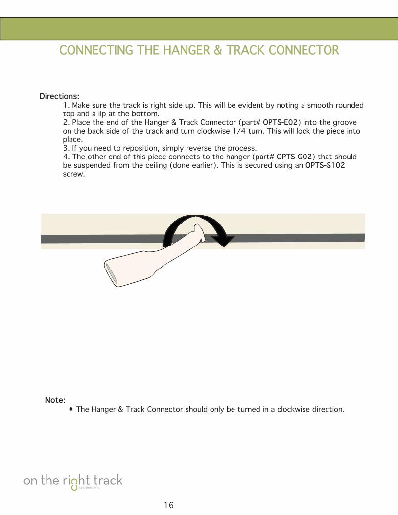
CONNECTINGTHEHANGER&TRACKCONNECTOR
Directions: 1. Make sure the track is right side up. This will be evident by noting a smooth rounded top and a lip at the bottom. 2. Place the end of the Hanger & Track Connector (part# OPTS-E02) into the groove on the back side of the track and turn clockwise 1/4 turn. This will lock the piece into place. 3.Ifyouneedtoreposition,simplyreversetheprocess. 4. The other end of this piece connects to the hanger (part# OPTS-G02) that should be suspended from the ceiling (done earlier). This is secured using an OPTS-S102 screw.
Note: • The Hanger & Track Connector should only be turned in a clockwise direction.
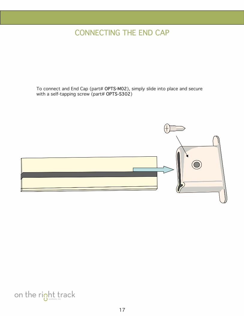
CONNECTING THE END CAP
17
To connect and End Cap (part# OPTS-M02), simply slide into place and secure with a self-tapping screw (part# OPTS-S302)
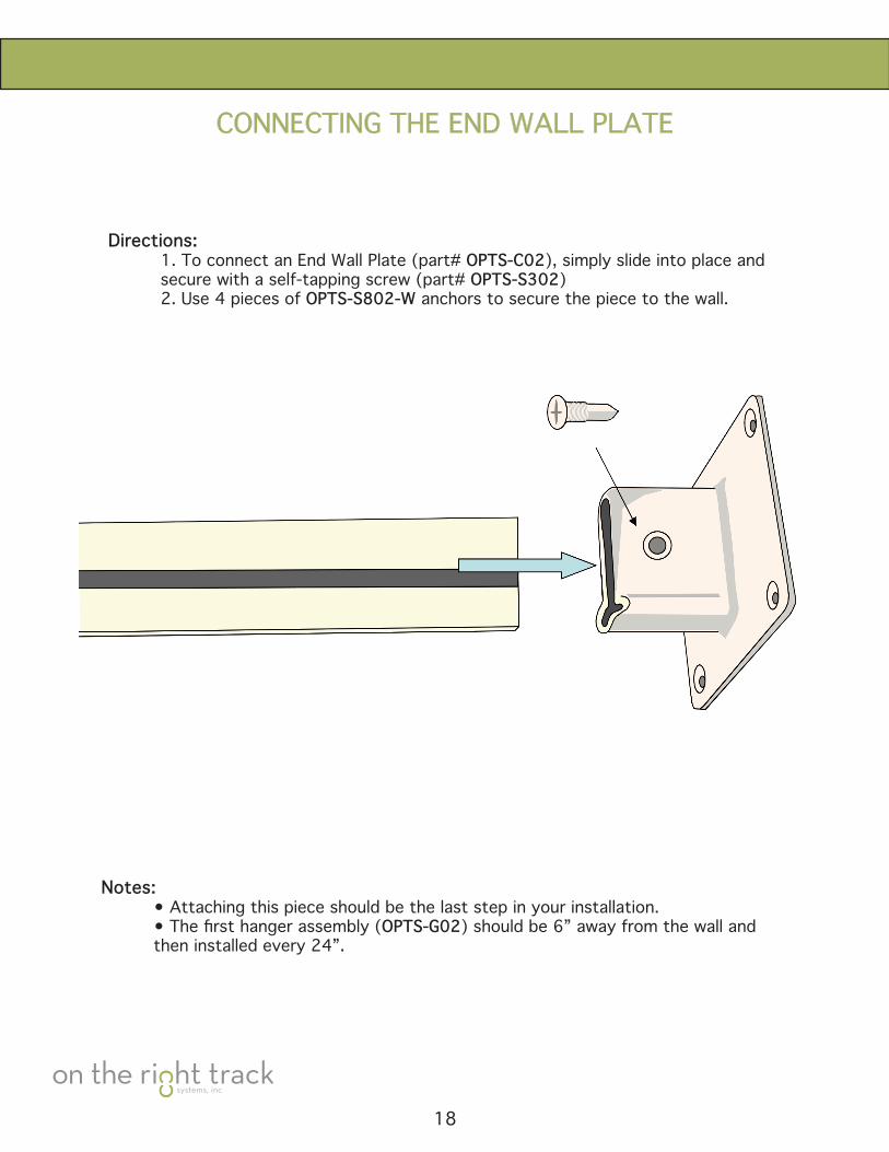
CONNECTING THE END WALL PLATE
Directions: 1. To connect an End Wall Plate (part# OPTS-C02), simply slide into place and secure with a self-tapping screw (part# OPTS-S302) 2. Use 4 pieces of OPTS-S802-W anchors to secure the piece to the wall.
Notes: • Attaching this piece should be the last step in your installation. •Thefirsthangerassembly(OPTS-G02) should be 6” away from the wall and then installed every 24”.
18
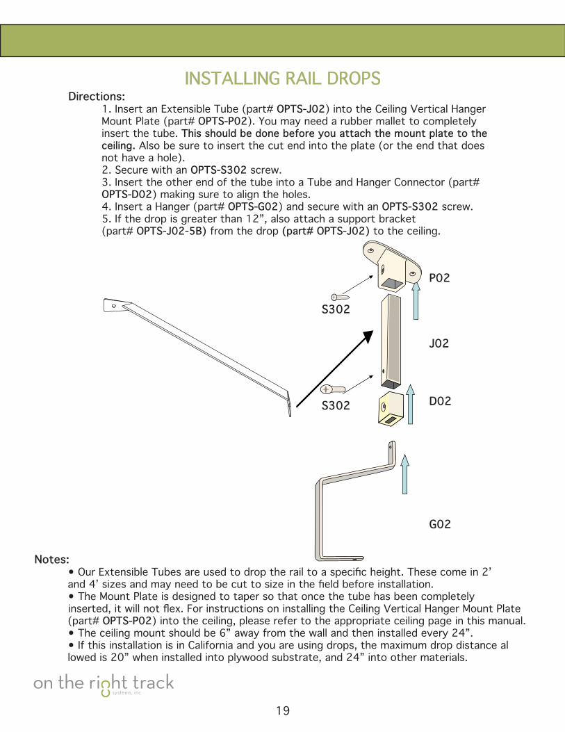
INSTALLING RAIL DROPSDirections: 1. Insert an Extensible Tube (part# OPTS-J02) into the Ceiling Vertical Hanger Mount Plate (part# OPTS-P02). You may need a rubber mallet to completely insert the tube. This should be done before you attach the mount plate to the ceiling. Also be sure to insert the cut end into the plate (or the end that does not have a hole). 2. Secure with an OPTS-S302 screw. 3.InserttheotherendofthetubeintoaTubeandHangerConnector(part# OPTS-D02) making sure to align the holes. 4. Insert a Hanger (part# OPTS-G02) and secure with an OPTS-S302 screw. 5. If the drop is greater than 12”, also attach a support bracket (part# OPTS-J02-5B) from the drop (part# OPTS-J02) to the ceiling.
Notes: •OurExtensibleTubesareusedtodroptherailtoaspecificheight.Thesecomein2’ and4’sizesandmayneedtobecuttosizeinthefieldbeforeinstallation. • The Mount Plate is designed to taper so that once the tube has been completely inserted,itwillnotflex.ForinstructionsoninstallingtheCeilingVerticalHangerMountPlate (part# OPTS-P02) into the ceiling, please refer to the appropriate ceiling page in this manual. • The ceiling mount should be 6” away from the wall and then installed every 24”. • If this installation is in California and you are using drops, the maximum drop distance al lowed is 20” when installed into plywood substrate, and 24” into other materials.
19
P02
J02
D02
G02
S302
S302
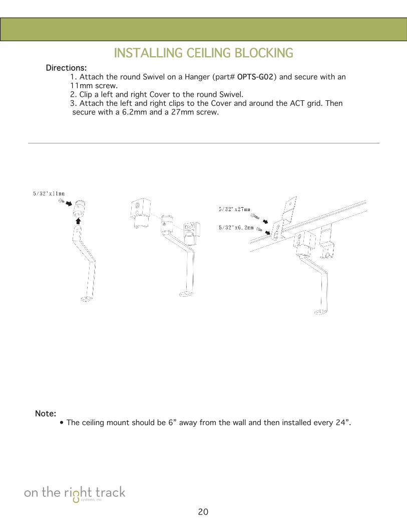
INSTALLINGCEILINGBLOCKINGDirections: 1. Attach the round Swivel on a Hanger (part# OPTS-G02) and secure with an 11mm screw. 2. Clip a left and right Cover to the round Swivel. 3.AttachtheleftandrightclipstotheCoverandaroundtheACTgrid.Then secure with a 6.2mm and a 27mm screw.
Note: • The ceiling mount should be 6” away from the wall and then installed every 24”.
20
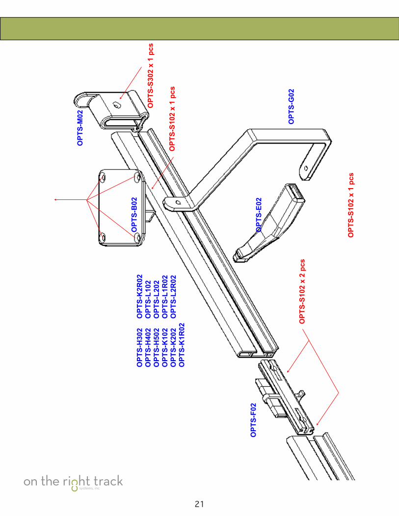
21
OPT
S-S1
02 x
1 p
cs
OPT
S-S3
02 x
1 p
cs
OPT
S-S1
02 x
1 p
cs
OPT
S-S1
02 x
2 p
cs
OPT
S-H
302
OPT
S-H
402
OPT
S-H
502
OPT
S-K
102
OPT
S-K
202
OPT
S-K
1R02
OPT
S-F0
2
OPT
S-B
02
OPT
S-M
02
OPT
S-G
02
OPT
S-E0
2
OPT
S-K
2R02
OPT
S-L1
02O
PTS-
L202
OPT
S-L1
R02
OPT
S-L2
R02

OPT
S-S3
02 x
1 p
cs
OPT
S-S1
02 x
1 p
cs
OPT
S-S1
02 x
2 p
cs
OPT
S-H
302
OPT
S-H
402
OPT
S-H
502
OPT
S-K
102
OPT
S-K
202
OPT
S-K
1R02
OPT
S-F0
2
OPT
S-C
02
OPT
S-G
02O
PTS-
E02
OPT
S-K
2R02
OPT
S-L1
02O
PTS-
L202
OPT
S-L1
R02
OPT
S-L2
R02
OPT
S-P0
2
OPT
S-J0
2
OPT
S-D
02
OPT
S-S8
02-W
x 4
pcs
(A
ttach
to W
all)
OPT
S-S3
02 x
1 p
cs
OPT
S-S3
02 x
1 p
cs
22
23
24
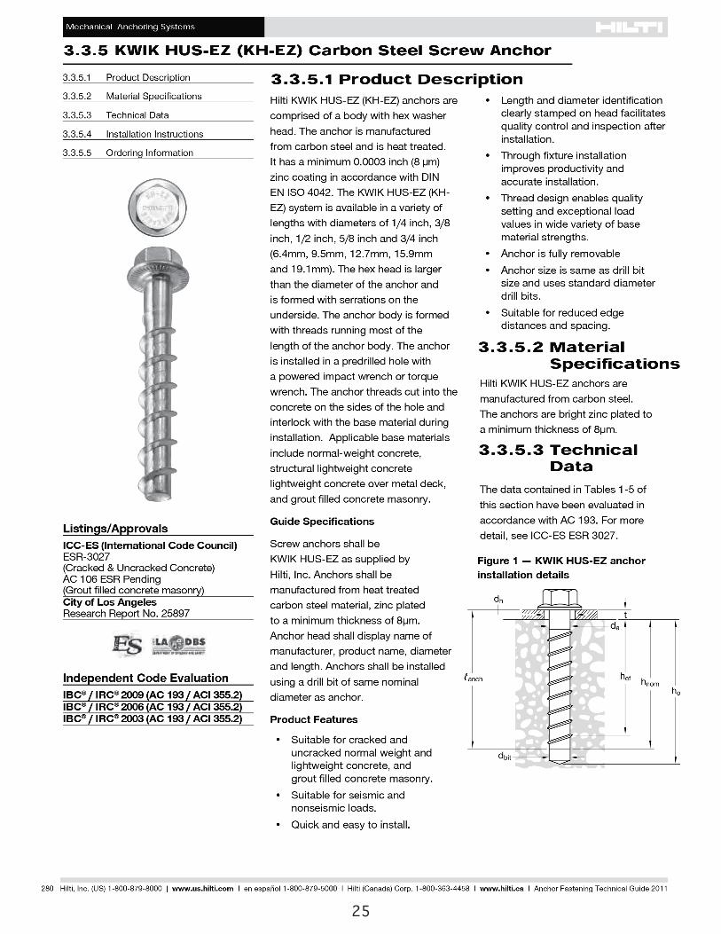
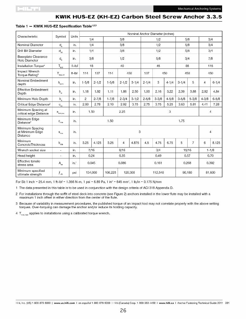
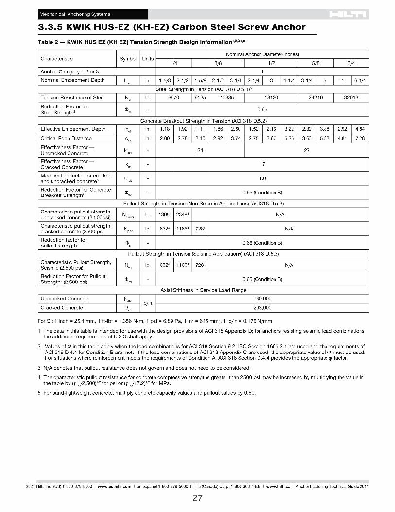
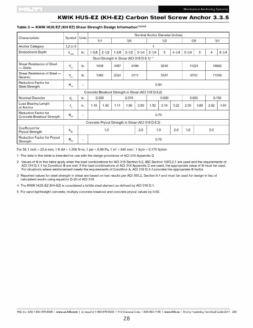
25
26
27
28
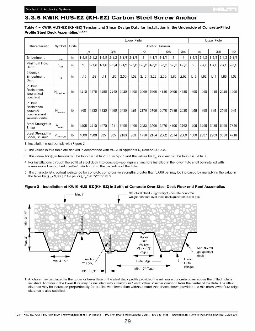
29
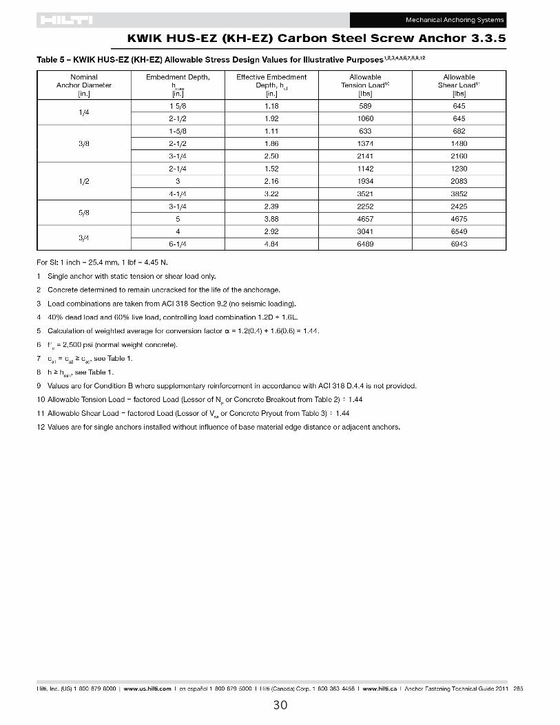
30
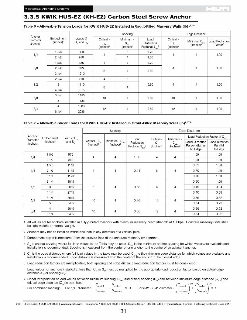
31
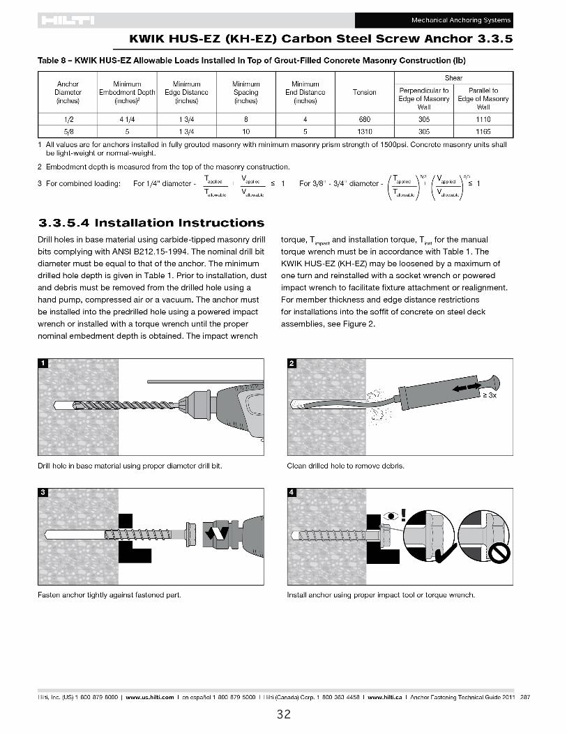
32
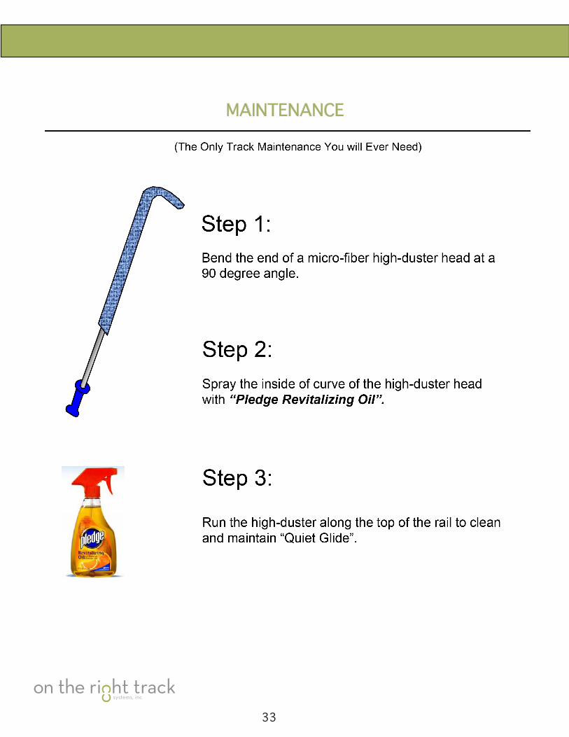
MAINTENANCE
33