on scenario synchronization - uni-bremen.de · on scenario synchronization duc-hanh dang 1,...
TRANSCRIPT
On Scenario Synchronization
Duc-Hanh Dang1, Anh-Hoang Truong1, and Martin Gogolla2
1University of Engineering and Technology,Vietnam National University of Hanoi,
144 Xuan Thuy, Cau Giay, Hanoi, Vietnam{hanhdd|hoangta}@vnu.edu.vn
2Department of Computer Science, University of Bremen,D-28334 Bremen, Germany
Abstract. In software development a system is often viewed by variousmodels at different levels of abstraction. It is very difficult to maintainthe consistency between them for both structural and behavioral seman-tics. This paper focuses on a formal foundation for presenting scenar-ios and reasoning the synchronization between them. We represent sucha synchronization using a transition system, where a state is viewedas a triple graph presenting the connection of current scenarios, anda transition is defined as a triple graph transformation rule. As a re-sult, the conformance property can be represented as a ComputationalTree Logic (CTL) formula and checked by model checkers. We define thetransition system using our extension of UML activity diagrams togetherwith Triple Graph Grammars (TGGs) incorporating Object ConstraintLanguage (OCL). We illustrate the approach with a case study of the re-lation between a use case model and a design model. The work is realizedusing the USE tool.
1 Introduction
In software development a system is viewed by various models at different lev-els of abstraction. Models are defined in different modeling languages such asUML [1] and DSMLs [2]. It is often very difficult to maintain the consistencybetween them as well as to explain such a relation for both structural and be-havioral semantics.
There are several approaches as introduced in [3, 2, 4] for behavioral semanticsof modeling languages. The behavior semantics can be defined as trace-based,translation-based, denotation-based, and execution-based semantics. Such a se-mantics can also be obtained by semantics mappings as pointed out in [5, 6]. Thesemantics can be represented by different formal methods such as graph trans-formation in [7], Z in [5, 8] for a full formal description for the Unified ModelingLanguage (UML), and Alloy in [9] for a semantics of modeling languages. Meta-modeling is another approach which allows us to define structural semantics ofmodels. Models from modeling languages like UML must conform to the corre-sponding metamodels, i.e., their well-formedness needs to be ensured. Constraint
1

languages for metamodels such as the Object Constraint Language (OCL) [10]allow us to express better structural semantics of models. In this context the re-lation between models can be obtained based on mappings between metamodels.On the mappings, transformation rules are defined for a model transformation.This principle is the core of many transformation tools and languages [11, 12] aswell as the Object Management Group (OMG) standard for model transforma-tion, Query/View/Transformation (QVT) [13].
This paper aims to describe an integrated view on two modeling languagesin order to characterize the semantics relation between them. Models within ourapproach are viewed as a set of execution scenarios of the system. We develop aformal foundation for presenting scenarios and reasoning the synchronization be-tween scenarios. We represent such a synchronization using a transition system,where a state is viewed as a triple graph presenting the connection of currentscenarios, and a transition is defined as a triple graph transformation rule. Asa result, the conformance property can be represented as a Computational TreeLogic (CTL) fomula and checked by model checkers. We define the transitionsystem using our extension of UML activity diagrams together with Triple GraphGrammars (TGGs) [14] incorporating Object Constraint Language (OCL) [15].
We illustrate our approach with a case study explaining the relation betweena use case model and a design model. Use cases [1, 16–18] have achieved wideacknowledgement for capturing and structuring software requirements. Our ap-proach not only allows us to check the conformance between use case and designmodels but also to describe operational semantics of use cases in particular andmodeling languages in general. We implement our approach based within theUML-based Specification Environment (USE) tool [19].
The rest of this paper is organized as follows. Section 2 presents preliminariesfor our work. Section 3 explains scenarios and the synchronization between themin an informal way. Section 4 focuses on the syntax and semantics aspects ofscenarios in order to form a formal foundation for scenario synchronization. Thecore is a transition system for the synchronization. Section 5 shows the CTLformula for the conformance property and explains our implementation in USE.Section 6 discusses related work. This paper is closed with a summary.
2 Preliminaries
This section presents preliminaries for our work. The definitions explained inthis section are adapted from the work in [20]. Models in our work are seen asgraphs. They are defined by a corresponding metamodel, which is representedas a type graph.
Definition 1. (Graphs and Graph Morphisms). A graph G =(GV , GE , sG, tG) consists of a set GV of nodes, a set GE of edges, and twofunctions sG, tG : GE → GV , the source and the target function.
Given graphs G, H a graph morphism f = (fV , fE) : G→ H consists of twofunctions fV : GV → HV and fE : GE → HE that preserve the source and the
2

target function, i.e., fV ◦ sG = sH ◦ fE and fV ◦ tG = tH ◦ fE. Graphs and graphmorphisms define the category Graph. A graph morphism f is injective if bothfunctions fV , fE are injective.
Definition 2. (Typing). A tuple (G, typeG) of a graph G = (V,E, s, t) togetherwith a graph morphism typeG : G→ TG, where TG is a graph, is called a typedgraph. Then, TG is called a type graph. Given typed graphs G = (G, typeG) andH = (H, typeH), a typed graph morphism f is a graph morphism f : G → H,such that typeH ◦ f = typeG.
State
name:String
StatecharttrOwner
Transition* **
src
0..1owner
*dst
*
* trigger0..1
1
1
Metamodel - Type graph
On Off
Switch
Model in concrete syntax
:State
name = 'Off'
:State
name = 'On'
:Statechart
:Event
name = 'Switch'
Eventname:String
:Transition
Model in abstract syntax - Typed graph
src
dst
owner
owner trOwner
Fig. 1. Statechart as a typed graph conforms to the metamodel as a type graph
Example. Model as graph; Metamodel as type graph: The simplifiedmetamodel which defines the structure of statecharts is represented by a typegraph as shown in Fig. 1. Instances of these node types (Statechart, State, Tran-sition, and Event) have to be linked according to the edge types between thenode types as well as attributed according to note type attributes.
In order to relate pair of models to each other, we will consider such a combi-nation as a triple graph. Then, a triple graph transformation allows us to buildstates of the integration.
Definition 3. (Triple Graphs and Triple Graph Morphisms).Three graphs SG, CG, and TG, called source, connection, and target graph,
together with two graph morphisms sG : CG → SG and tG : CG → TG form a
triple graph G = (SGsG← CG
tG→ TG). G is called empty, if SG, CG, and TG
are empty graphs.A triple graph morphism m = (s, c, t) : G → H between two triple graphs
G = (SGsG← CG
tG→ TG) and H = (SHsH← CH
tH→ TH) consists of threegraph morphisms s : SG → SH, c : CG → CH and t : TG → TH suchthat s ◦ sG = sH ◦ c and t ◦ tG = tH ◦ c. It is injective, if morphisms s, c
3
and t are injective. Triple graphs and triple graph morphisms form the categoryTripleGraph.
:Statechart
refined
eha:EHAs2e:SC2EHA
c2s1:S2SH
s2a1:St2Aut
c2s2:S2SH
s2a2:St2Aut
onStateH:StateH
name = 'On'
lampAut:Automata
name = 'Lamp'
redStateH:StateH
name = 'Red'
counterAut:Automata
name = 'Red'
onState:CompState
isConcurr=true
name='On'
lampState:CompState
isConcurr=false
name='Lamp'
redState:CompState
isConcurr=false
name='Red'
ownerownerowner
container
refined
owner
owner
container
container
ehasc
Fig. 2. Triple graph for an integrated SC2EHA model
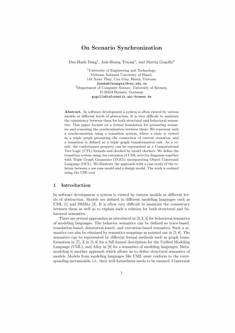
Example. Triple graph: The graph in Fig. 2 shows a triple graph containinga statechart together with correspondence nodes pointing to the extended hier-archical automata (EHA). References between source and target models denotetranslation correspondences. For a detailed explanation of the transformation,we refer to the work in [21].
Definition 4. (Triple Graph Transformation Systems).
A triple rule tr = Ltr→ R consists of triple graphs L and R and an injective
triple graph morphisms tr.
(SL
(SR
CL
CR
TL)
TR)
ts
sR tR
tLsL
L =
R =
tr c
Given a triple rule tr = (s, c, t) : L→ R, a triple graph G and a triple graphmorphism m = (sm, cm, tm) : L → G, called triple match m, a triple graph
transformation step Gtr,m=⇒ H from G to a triple graph H is given by three objects
SH, CH and TH in category Graph with induced morphisms sH : CH → SH
and tH : CH → TH. Morphism n = (sn, cn, tn) is called comatch.
4
(SG
(SH
CG
CH
TG)
TH)
t’s’
sH tH
G =
H =
tr
SL
SR
CL
CR
TL
TR
tmsm
c’
cm
tnsn cn
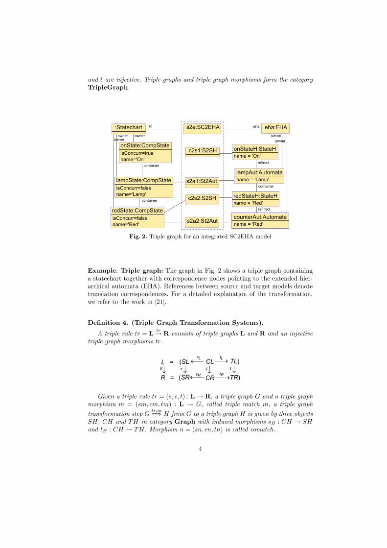
A triple graph transformation system is a structure TGTS = (S, TR) whereS is an initial graph and TR = {tr1, tr2, ...., trn} is a set of triple rules. Triplegraphs in the set {G|S ⇒∗ G} are referred to as reachable states.
s2e:SC2EHA
s:SimpState
name
sc:Statechart
sH:StateH
names2sH:S2SH
eha:EHA
aut:Automata
name
{new}{new}
{new}
Fig. 3. Triple rule for SC2EHA model transformation
Example. Triple rule: The rule in Fig. 3 is part of a triple graph transformationsystem that generates statecharts and corresponding EHA models, as introducedin [21]. This rule may create a simple state of a statechart and its correspondingstate of the corresponding EHA model at any time.
3 Scenarios and Synchronization
This section explains scenarios and scenario synchronization in an informal way.We focus on activity diagrams and their extensions as a means to present scenar-ios. Activity diagrams normally allow us to present scenarios at different levelsof abstraction, ranging from the very high level such as workflows to lower levelssuch as execution scenarios of programs. However, they only emphasize the flowsin scenarios, and the meaning of actions is not available so that the informationof scenarios is often not completely captured by this kind of diagrams. We re-fine activity diagrams by adding into each action a pair of interrelated objectdiagrams attached with OCL conditions as pre- and postconditions of the action.
With the extension the semantics of activity diagrams needs to be updated.The key question is how a scenario is defined for each system execution froma specification using extended activity diagrams. Normally, pre- and postcon-ditions for each action do not completely capture the effect of the action, werefer to such activity diagrams as declarative activity diagrams. Figure 4 shows
5
Require system to process as a car is returned
Retrieve information of the rental
Supply informationof the rental
Update informationto finish the rental
Process the paymentfor the rental
Actor System
id_Cust:StringCls[id_Cust.string<>oclUndefined(String)]
mileage_Car:RealCls[mileage_Car.real<> oclUndefined(Real)]
Return Late
cust:Customerrental:Rentalid_Cust:StringCls(cust,rental):Registration[cust.id=id_Cust.string]
[else]
[T]
post
post
rental:Rentalcar:Carmileage_Car:RealCls(rental,car):UsingCar
rental:Rentalcar:Carmileage_Car:RealCls(rental,car):UsingCar[car.mileage= mileage_Car.real]
pre
post
rental:RentaltoDay:DateCls[rental.finish <today.date]
1
2
3
4
5
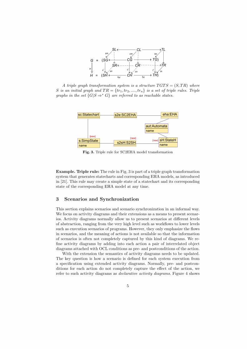
Fig. 4. Scenarios at the use case level of the use case “ReturnCar” presented by declar-ative activity diagrams
an example for declarative activity diagrams. This diagram presents scenariosof the use case “ReturnCar”, which describes a fragment of the service of a carrental system. In the diagram, use case snapshots, which include objects, links,and OCL conditions, are denoted by rectangles. Here, we use concepts of theconceptual domain of the system in order to present use case snapshots. Systemand actor actions, e.g., the actions (1) and (4) are denoted by rounded rectan-gles. Use case actions, e.g., the action (5) are denoted by the double-line roundedrectangles. A conditional action, e.g., the action (2) is denoted by the dashed-linerounded rectangles. The extension point, e.g., the Return Late extension pointof the action (4), is denoted by the six-sided polygons.
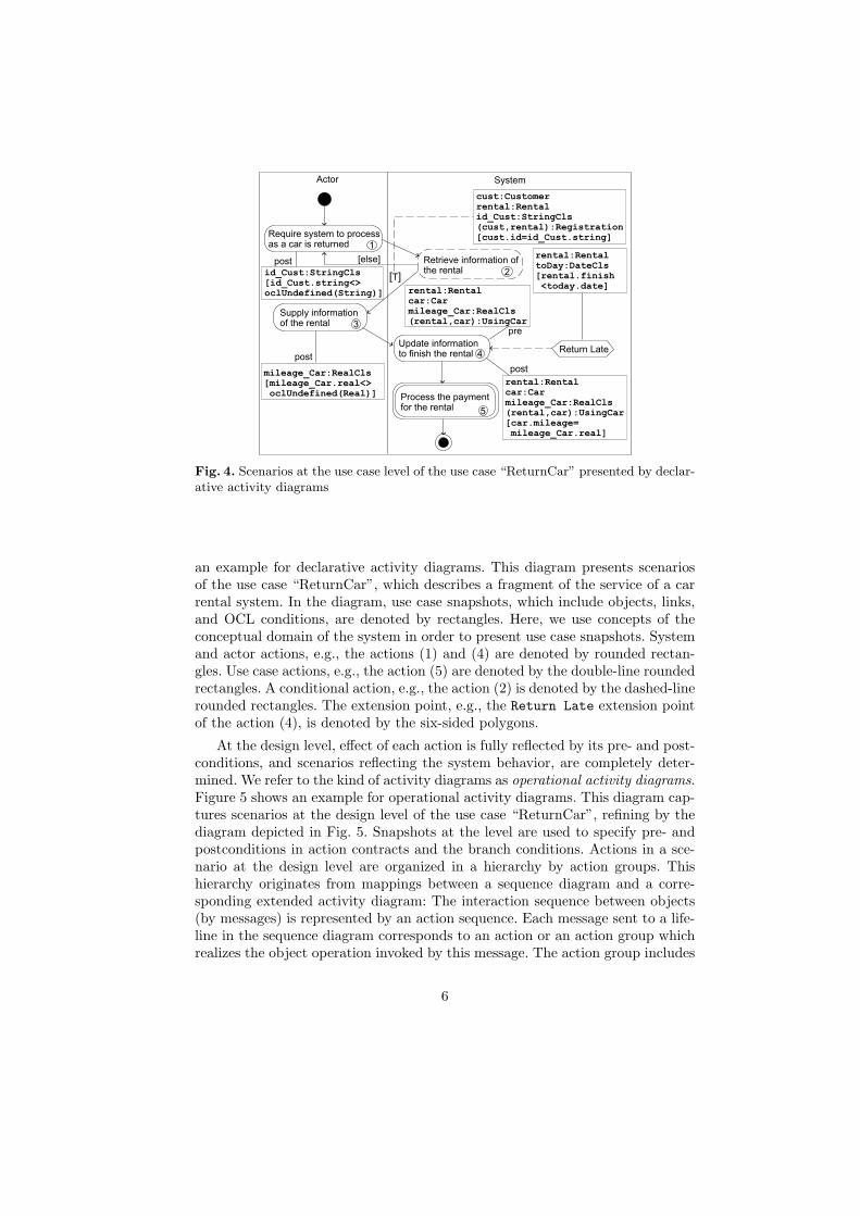
At the design level, effect of each action is fully reflected by its pre- and post-conditions, and scenarios reflecting the system behavior, are completely deter-mined. We refer to the kind of activity diagrams as operational activity diagrams.Figure 5 shows an example for operational activity diagrams. This diagram cap-tures scenarios at the design level of the use case “ReturnCar”, refining by thediagram depicted in Fig. 5. Snapshots at the level are used to specify pre- andpostconditions in action contracts and the branch conditions. Actions in a sce-nario at the design level are organized in a hierarchy by action groups. Thishierarchy originates from mappings between a sequence diagram and a corre-sponding extended activity diagram: The interaction sequence between objects(by messages) is represented by an action sequence. Each message sent to a life-line in the sequence diagram corresponds to an action or an action group whichrealizes the object operation invoked by this message. The action group includes
6
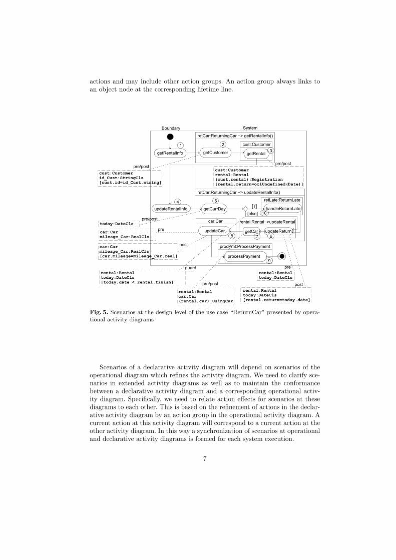
actions and may include other action groups. An action group always links toan object node at the corresponding lifetime line.
Boundary
getRentalInfo getCustomer getRental
retCar:ReturningCar −> getRentalInfo()
cust:Customer
pre/post
1 2
3
cust:Customerid_Cust:StringCls[cust.id=id_Cust.string]
today:DateCls
rental:Rentalcar:Car(rental,car):UsingCar
System
updateRentalInfo handleReturnLate
updateReturn
getCurrDay
processPayment
retCar:ReturningCar −> updateRentalInfo()
rental:Rental−>updateRental
retLate:ReturnLate
procPmt:ProcessPayment
[T]
[else]
cust:Customerrental:Rental(cust,rental):Registration[rental.return=oclUndefined(Date)]
pre/post
getCarupdateCar
car:Carpre/post
rental:Rentaltoday:DateCls
car:Carmileage_Car:RealCls
pre/post
car:Carmileage_Car:RealCls[car.mileage=mileage_Car.real]
pre
post
rental:Rentaltoday:DateCls[rental.return=today.date]
pre
post
4 5
678
9
10
rental:Rentaltoday:DateCls[today.date < rental.finish]
guard
Fig. 5. Scenarios at the design level of the use case “ReturnCar” presented by opera-tional activity diagrams
Scenarios of a declarative activity diagram will depend on scenarios of theoperational diagram which refines the activity diagram. We need to clarify sce-narios in extended activity diagrams as well as to maintain the conformancebetween a declarative activity diagram and a corresponding operational activ-ity diagram. Specifically, we need to relate action effects for scenarios at thesediagrams to each other. This is based on the refinement of actions in the declar-ative activity diagram by an action group in the operational activity diagram. Acurrent action at this activity diagram will correspond to a current action at theother activity diagram. In this way a synchronization of scenarios at operationaland declarative activity diagrams is formed for each system execution.
7
4 Scenarios and Synchronization, Formally
First, we focus on the syntax of extended activity diagrams in order to presentscenarios. Then, we consider the semantics aspect, where an operational seman-tics for extended activity diagrams is defined. We aim to build a transition systemreflecting the synchronization between scenarios.
4.1 Syntax Aspect
Similar to the work in [22], we also restrict our consideration to well-structuredactivity diagrams: The building blocks are only sequences, fork-joins, decisions,and loops. We define new meta-concepts in addition to the UML metamodel inorder to present extended activity diagrams. Due to the limited space, conceptsof the metamodels are only shown in triple rules in the Appendix section, insteadof a detailed explanation. Here, we refer to them, i.e., metamodels of declarativeand operational activity diagram as graphs DG and OG, respectively.
Definition 5. (Declarative Activity Diagrams). A declarative activity di-agram is a graph typed by the graph DG, where DG is a graph corresponding tothe metamodel for declarative activity diagrams.
Definition 6. (Operational Activity Diagrams). An operational activitydiagram is a graph typed by the graph OG, where OG is a graph correspondingto the metamodel for operational activity diagrams.
Note that each Action object node in the DG and OG graphs, which rep-resent an action, is attached with SnapshotPattern object nodes, which expresspre- and postconditions of the action, respectively. The attribute snapshot of aSnapshotPattern node is a graph whose nodes are variables. This graph is typedby the graph CD, which is a graph corresponding to the class diagram of thesystem (i.e., a system state is a graph typed by CD). For example, Fig. 4 showsSnapshotPatterns as the pre- and postcondition of the action marked by (4).
Well-formedness of extended activity diagrams can be ensured using OCLconditions. For example, it ensures that an activity diagram has exactly oneInitialNode and ActivityFinalNode.
4.2 Semantics Aspect - Synchronization by a Transition System
Activity diagrams basically have a Petri-like semantics. However, as discussedin Sect. 3 scenarios from declarative and operational activity diagrams dependwith each other. In order to obtain an operational semantics for these extendedactivity diagrams, we have to define a pair of scenarios in synchronization foreach system execution. This section clarifies what a current state of the synchro-nization is and which transitions are used for it.
8
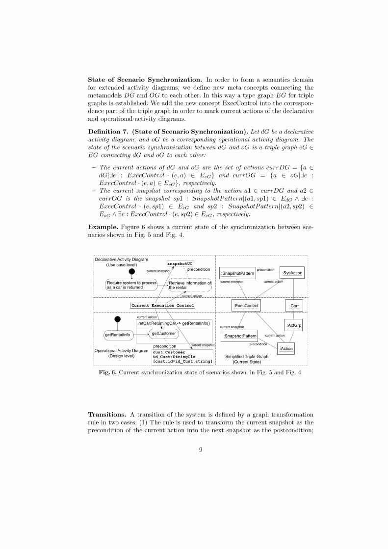
State of Scenario Synchronization. In order to form a semantics domainfor extended activity diagrams, we define new meta-concepts connecting themetamodels DG and OG to each other. In this way a type graph EG for triplegraphs is established. We add the new concept ExecControl into the correspon-dence part of the triple graph in order to mark current actions of the declarativeand operational activity diagrams.
Definition 7. (State of Scenario Synchronization). Let dG be a declarativeactivity diagram, and oG be a corresponding operational activity diagram. Thestate of the scenario synchronization between dG and oG is a triple graph eG ∈EG connecting dG and oG to each other:
– The current actions of dG and oG are the set of actions currDG = {a ∈dG|∃e : ExecControl · (e, a) ∈ EeG} and currOG = {a ∈ oG|∃e :ExecControl · (e, a) ∈ EeG}, respectively.
– The current snapshot corresponding to the action a1 ∈ currDG and a2 ∈currOG is the snapshot sp1 : SnapshotPattern|(a1, sp1) ∈ EdG ∧ ∃e :ExecControl · (e, sp1) ∈ EeG and sp2 : SnapshotPattern|(a2, sp2) ∈EoG ∧ ∃e : ExecControl · (e, sp2) ∈ EeG, respectively.
Example. Figure 6 shows a current state of the synchronization between sce-narios shown in Fig. 5 and Fig. 4.
getRentalInfo getCustomer
retCar:ReturningCar -> getRentalInfo()
precondition
cust:Customerid_Cust:StringCls[cust.id=id_Cust.string]
Require system to processas a car is returned
Retrieve information ofthe rental
Current Execution Control
snapshotUCDeclarative Activity Diagram
(Use case level)
Operational Activity Diagram
(Design level)
precondition
current action
current snapshot
current action
current snapshot:SysAction:SnapshotPattern
:ExecControl
:Action
:ActGrp
:SnapshotPattern
Simplified Triple Graph
(Current State)
:Corr
current snapshot
current snapshot current action
current action
precondition
precondition
Fig. 6. Current synchronization state of scenarios shown in Fig. 5 and Fig. 4.
Transitions. A transition of the system is defined by a graph transformationrule in two cases: (1) The rule is used to transform the current snapshot as theprecondition of the current action into the next snapshot as the postcondition;
9
(2) The rule is used to transform the current state (as a triple graph) to the nextstate by selecting the next current actions. The first case is referred to as snapshottransitions. The transition rules are defined according to the specification ofthe system. The second case is referred to as action transitions. The transitionrules are defined based on the refinement relation between a declarative activitydiagram and an operational activity diagram as discussed in Sect. 3. The rulesare independent with a concrete system.
Definition 8. (Snapshot Transition). A snapshot transition is a triple rulewhich allows us to transform a state eG1 to the next state eG2 such that thecurrent actions are unchanged and only the current snapshot of dG or oG ischanged from as the precondition snapshot to the postcondition snapshot by acorresponding graph transformation rule. This postcondition snapshot needs tobe fulfilled.
Example. Let us consider the synchronization between scenarios shown in Fig. 5and Fig. 4. A snapshot transition will transfer from the current state, which refersto the action (4) and its precondition snapshot (as depicted in Fig. 4), to thenext state which refers to the postcondition snapshot of this action.
Definition 9. (Action Transition). An action transition is a triple rule whichallows us to transform a state eG1 to the next state eG2 such that the currentactions and the current snapshots are changed and the current snapshots as theprecondition of the current actions in eG2 are fulfilled.
Example. An action transition will transfer from the current state, which refersto the action (4) shown in Fig. 4 and the action (8) shown in Fig. 5, to the nextstate which refers to the action (5) and action (9) of these scenarios.
Definition 10. (Sound and Conformance Property). Let TS = (S,→, s0)be a transition system, where s0 is the initial state, i.e., the current actions arethe initial actions of the declarative and operational activity diagrams dG andoG; S is a set of reachable states from s0 by snapshot transitions SR and actiontransitions AR. The activity diagrams dG and oG are sound and conformed toeach other if and only if the following conditions hold:
1. ∀s ∈ S · ∃sys0, ..., sysn : CD · (sirk∈SR−→ si+1 ⇒ sysk
rk→ sysk+1) ∧ ∃e :ExecControl · ∀sp : SnapshotPattern · (e, sp) ∈ Es ⇒ isV alid(sp, sysn),where isV alid(sp, sysn) indicates the graph sp conforms to the graph sysn.
2. ∀sys : CD · ∃s1, ..., sn ∈ S · (si → si+1∧ isF inalState(sn)∧ (sirk∈SR−→ si+1 ⇒
syskrk→ sysk+1) ∧ sys0 = sys, where isF inalState(sn) indicates sn is the
final state, i.e., the ExecControl object node of this triple graph points to thefinal nodes of dG and oG.
In this definition Condition 1 ensures that each snapshot in the snapshotsequence corresponding to the scenario from dG and oG is valid. Condition 2ensures that we can always define a pair of scenarios for a system executionstarting from a sys state.
10
5 Conformance Property and Tool Support
We aim to obtain an automatic check for the sound and conformance propertymentioned above. To utilize model checkers for the goal we need to translate theconditions of Def. 10 into CTL, i.e., the notion of temporal logic most modelcheckers understand. Now we briefly define the CTL formulas we will use toexpress our conditions. Note that this is only a subset of CTL.
Definition 11. (CTL Formulas). Let TS = (S,→, s0) be a transition systemby snapshot transitions and action transitions. Let Comp(s0) be all possible com-putations starting with the state s0: Comp(s) := {s0s1s2...|(si, si+1) ∈→}, andlet p be some atomic proposition. Then
TS |= AG(p)⇔ ∀s0s1... ∈ Comp(s0)∀k ∈ N : p holds in sk
TS |= AF(p)⇔ ∀s0s1... ∈ Comp(s0)∃k ∈ N : p holds in sk
TS |= EF(p)⇔ ∃s0s1... ∈ Comp(s0)∃k ∈ N : p holds in sk
We are now ready to formulate our theorem.
Theorem 1. Let dG and oG be the declarative and operational activity dia-grams, respectively. Let TS = (S,→, s0) be a transition system by snapshottransitions and action transitions (S contains exactly those states which arereachable from s0). dG and oG are sound and conformed to each other if andonly if the following CTL formulas hold for TS:
1. TS |= AG(isV alidSnapshot), where that isV alidSnapshot holds in thestate s, denoted as s |= isV alidSnapshot, means the current SnapshotPat-tern objects of s are valid.
2. TS |= EF(AtFinalState), where that AtFinalState holds in the state s, de-noted as s |= AtFinalState, means the ExecControl object node of this triplegraph (s) points to the final nodes of dG and oG.
Proof. We start by pointing out the equivalence of the first condition ofDef. 10 and Theor. 1. We have TS |= AG(isV alidSnapshot) ⇔ ∀s0s1... ∈Comp(s0)∀k ∈ N : sk |= isV alidSnapshot ⇔ ∀s0s1... ∈ Comp(s0)∀k ∈
N · ∃sys0, sys1, ..., sysm : CD · (sirl∈SR−→ si+1 ⇒ sysl
rl→ sysl+1) ∧ (sk |=isV alidSnapshot). Since sk |= isV alidSnapshot ⇔ ∃e : ExecControl · ∀sp :SnapshotPattern · (e, sp) ∈ Esk
→ isV alid(sp, sysm) this induces the equiva-lence of the first condition of Def. 10 and Theor. 1.
We will show that Condition 2 of Def. 10 and Theor. 1 is equivalent.We have TS |= EF(AtFinalState) ⇔ ∃s0s1... ∈ Comp(s0)∃k ∈ N : sk |=AtFinalState ⇔ ∀sys0 : CD · ∃s0s1... ∈ Comp(s0)∃k ∈ N∃sys1, ..., sysm :
CD · (sirl∈SR−→ si+1 ⇒ sysl
rl→ sysl+1) : sk |= AtFinalState ⇔ ∀sys0 : CD ·
∃s0, ..., sk ∈ S ·(si → si+1)∧isF inalState(sk)∧(sirl∈SR−→ si+1 ⇒ sysl
rl→ sysl+1).This induces the equivalence Condition 2 of Def. 10 and Theor. 1.�
Our formal framework has been applied for the running example as depictedin Fig. 4 and Fig. 5: It allows us to check the conformance between use case and
11
design models. With the case study we have defined 10 triple rules for actiontransitions. Due to the limited space of this paper, they are only shown in theAppendix section for reviewers.
We employ the USE tool and its extensions for the implementation. Thistool allows us to animate and validate such a scenario synchronization. WithUSE we can present the declarative and operational activity diagrams as well-formed models since USE supports the specification of metamodels together withOCL conditions. Snapshot transitions and action transitions will be realized asoperations in USE. Then, we can carry out transitions of our TS transitionsystem and animate states as object diagrams. Currently, the process is realizedin a semi-automatic way. This is suitable for designers to check their design atthe early phase of the development process. For an automatic check, we plan toemploy the USE feature which supports generating snapshots [23]. Then, CTLformulas can be automatically checked. This point belongs to future work.
6 Related Work
Triple Graph Grammars (TGGs) [14] have been a promising approach forexplaining relationships between models, especially, bidirectional transforma-tions. Several tools support model transformation based on TGGs such asMOFLON [12] and AToM3 [24].
Many approaches to model transformation have been introduced. ATL [11]and Kermeta [25] are well-known systems supporting transformation lan-guages. They aim to realize the Query/View/Transformation (QVT) [13] stan-dard for model transformation, which is proposed by the Object ManagementGroup (OMG).
Many researches as surveyed in [26] have been attempted to introduce rigorinto use case descriptions. The works in [27, 28] propose viewing use cases fromthe different levels of abstraction. Many works focus on defining a formal seman-tics of use cases. They are strongly influenced by UML. The formal semanticsof use cases in the works is often based on activity diagram or state charts. Theworks in [29, 30] employ the metamodel approach in order to form a conceptualframe for use case modeling. The work in [27] proposes use case charts as anextension of activity diagram in order to define a trace-based semantics of usecases. The works in [31–33] propose using state charts to specify use cases. Theiraim is to generate test cases from the use case specification.
The works in [22, 7] propose using graph transformation to specify use cases,which are seen as activity diagrams. Those works employ the technique analyzinga critical pair of rule sequences in order to check the dependency between usecase scenarios. Our work for design scenarios is similar to that work. Unlike themwe employ OCL conditions in order to express action contracts.
This paper continues our proposal for the approach to use cases in [34, 35].The core of this approach is viewing use cases as a sequence of use case snap-shots and using the integration of TGGs and OCL to define this sequence. Theintegration of TGGs and OCL is proposed in our previous work in [15, 36].
12
7 Conclusion and Future Work
We have introduced a novel approach to explain the relation of behavioral se-mantics between models at different levels of abstraction. The heart of it isto analyse scenarios and scenario synchronization. We have developed a theoryframework for the aim. This framework is examined with the case study con-cerning the relation between a use case model and a design model. It brings outa method to check the conformance between use case and design models. Thiswork is implemented using the USE tool.
In future we continue to refine our theory framework so that we can analysebetter on scenarios. Exploring triple rules as transitions of the transition sys-tem for scenario synchronization is also a focus of our future work. Besides, wewill enhance the USE tool in order to obtain more support for the new tasks,especially, for checking CTL formulas.
References
1. OMG: OMG Unified Modeling Language (OMG UML), Superstructure, V2.1.2.OMG (November 2007)
2. Greenfield, J., Short, K., Cook, S., Kent, S.: Software Factories: Assembling Ap-plications with Patterns, Models, Frameworks, and Tools. 1st edn. Wiley (August2004)
3. Kleppe, A.G.: A Language Description is More than a Metamodel. In: FourthInternational Workshop on Software Language Engineering, 1 Oct 2007, Nashville,USA, http://planet-mde.org/atem2007/ (October 2007)
4. Harel, D., Rumpe, B.: Meaningful Modeling: What’s the Semantics of ”Semantics”?Computer 37(10) (2004) 64–72
5. Broy, M., Crane, M., Dingel, J., Hartman, A., Rumpe, B., Selic, B.: 2nd UML2 Semantics Symposium: Formal Semantics for UML. In: Models in SoftwareEngineering. Volume 4364 of LNCS., Springer Berlin (2007) 318–323
6. Gogolla, M.: (An Example for) Metamodeling Syntax and Semantics of Two Lan-guages, their Transformation, and a Correctness Criterion. In Bezivin, J., Heckel,R., eds.: Proc. Dagstuhl Seminar on Language Engineering for Model-Driven Soft-ware Development, http://www.dagstuhl.de/04101/ (2004)
7. Hausmann, J.H., Heckel, R., Taentzer, G.: Detection of Conflicting FunctionalRequirements in a Use Case-Driven approach: a static analysis technique basedon graph transformation. In: Proceedings of the 22rd International Conference onSoftware Engineering, ICSE 2002, 19-25 May 2002, Orlando, Florida, USA, ACM(2002)
8. Evans, A., France, R.B., Lano, K., Rumpe, B.: The UML as a Formal ModelingNotation. In Bezivin, J., Muller, P., eds.: The Unified Modeling Language. UML98:Beyond the Notation First International Workshop, Mulhouse, France, June 3-4,1998. Selected Papers. Volume 1618 of LNCS., Springer-Verlag (1999) 336–348
9. Kelsen, P., Ma, Q.: A Lightweight Approach for Defining the Formal Semanticsof a Modeling Language. In: Model Driven Engineering Languages and Systems,11th International Conference, MoDELS 2008, Toulouse, France, September 28 -October 3, 2008. Proceedings. Volume 5301., Springer Berlin (2008) 690–704
13
10. Warmer, J.B., Kleppe, A.G.: The Object Constraint Language: Precise ModelingWith Uml. 1st edn. Addison-Wesley Professional (1998)
11. Jouault, F., Allilaire, F., Bezivin, J., Kurtev, I.: ATL: A model transformationtool. Science of Computer Programming 72(1-2) (June 2008) 31–39
12. Amelunxen, C., Konigs, A., Rotschke, T., Schurr, A.: MOFLON: A Standard-Compliant Metamodeling Framework with Graph Transformations. In Rensink,A., Warmer, J., eds.: Model Driven Architecture – Foundations and Applications.Volume 4066., Springer Berlin (2006) 361–375
13. OMG: Meta Object Facility (MOF) 2.0 Query/View/Transformation Specification,Final Adopted Specification ptc/07-07-07. OMG (2007)
14. Schurr, A.: Specification of Graph Translators with Triple Graph Grammars.In Schmidt, M., ed.: Proceedings of the 20th International Workshop on Graph-Theoretic Concepts in Computer Science. Volume 903 of LNCS., Springer-Verlag(1995) 151–163
15. Dang, D.H., Gogolla, M.: On Integrating OCL and Triple Graph Grammars. InChaudron, M., ed.: Models in Software Engineering, Workshops and Symposia atMODELS 2008, Toulouse, France, September 28 - October 3, 2008. Reports andRevised Selected Papers. Volume 5421., Springer (2009) 124–137
16. Rumbaugh, J., Jacobson, I., Booch, G.: The Unified Modeling Language ReferenceManual, 2nd Edition. Addison-Wesley Professional (2004)
17. Cockburn, A.: Writing Effective Use Cases. 1st edn. Addison-Wesley Professional(2000)
18. Jacobson, I.: Object-Oriented Software Engineering: A Use Case Driven Approach.1st edn. Addison-Wesley Professional, USA (June 1992)
19. Gogolla, M., Buttner, F., Richters, M.: USE: A UML-Based Specification Envi-ronment for Validating UML and OCL. Science of Computer Programming (2007)
20. Hartmut Ehrig and Claudia Ermel and Frank Hermann: On the Relationship ofModel Transformations Based on Triple and Plain Graph Grammars. In: Proceed-ings of the third international workshop on Graph and model transformations,ACM (2008) 9–16
21. Dang, D.H., Gogolla, M.: Precise Model-Driven Transformation Based on Graphsand Metamodels. In Hung, D.V., Krishnan, P., eds.: 7th IEEE International Con-ference on Software Engineering and Formal Methods, 23-27 November, 2009,Hanoi, Vietnam, IEEE Computer Society Press (2009) 1–10
22. Jurack, S., Lambers, L., Mehner, K., Taentzer, G.: Sufficient Criteria for ConsistentBehavior Modeling with Refined Activity Diagrams. In Czarnecki, K., Ober, I.,Bruel, J., Uhl, A., Volter, M., eds.: Model Driven Engineering Languages and Sys-tems, 11th International Conference, MoDELS 2008, Toulouse, France, September28 - October 3, 2008. Proceedings. Volume 5301 of LNCS., Springer (2008) 341–355
23. Gogolla, M., Bohling, J., Richters, M.: Validating UML and OCL Models in USEby Automatic Snapshot Generation. Software and System Modeling 4(4) (2005)386–398
24. de Lara, J., Vangheluwe, H.: AToM3: A Tool for Multi-formalism and Meta-modelling. In: Proceedings of the 5th International Conference on FundamentalApproaches to Software Engineering, Springer-Verlag (2002) 174–188
25. Muller, P.A., Fleurey, F., Jezequel, J.M.: Weaving Executability into Object-Oriented Meta-languages. In: Model Driven Engineering Languages and Systems.Volume 3713., Springer Berlin (2005) 264–278
26. Hurlbut, R.R.: A Survey of Approaches for Describing and Formalizing Use Cases.Technical Report XPT-TR-97-03, Department of Computer Science, Illinois Insti-tute of Technology, USA (1997)
14
27. Whittle, J.: Specifying Precise Use Cases with Use Case Charts. In Bruel, J., ed.:Satellite Events at the MoDELS 2005 Conference, MoDELS 2005 InternationalWorkshops, Doctoral Symposium, Educators Symposium, Montego Bay, Jamaica,October 2-7, 2005, Revised Selected Papers, Springer, LNCS 3844 (2006) 290–301
28. Regnell, B., Andersson, M., Bergstrand, J.: A Hierarchical Use Case Model withGraphical Representation. In: IEEE Symposium and Workshop on Engineeringof Computer Based Systems (ECBS’96), March 11-15, 1996, Friedrichshafen, Ger-many, IEEE Computer Society (1996) 270
29. Smialek, M., Bojarski, J., Nowakowski, W., Ambroziewicz, A., Straszak, T.: Com-plementary Use Case Scenario Representations Based on Domain Vocabularies. InEngels, G., Opdyke, B., Schmidt, D.C., Weil, F., eds.: Model Driven EngineeringLanguages and Systems, Springer Berlin, LNCS 4735 (2007) 544–558
30. Duran, A., Bernardez, B., Genero, M., Piattini, M.: Empirically Driven Use CaseMetamodel Evolution. In Baar, T., Strohmeier, A., Moreira, A.M.D., Mellor, S.J.,eds.: UML 2004 - The Unified Modelling Language: Modelling Languages andApplications. 7th International Conference, Lisbon, Portugal, October 11-15, 2004.Proceedings, Springer, LNCS 3273 (2004) 1–11
31. Sinha, A., Paradkar, A., Williams, C.: On Generating EFSM Models from UseCases. In: ICSEW ’07: Proceedings of the 29th International Conference on Soft-ware Engineering Workshops, IEEE Computer Society (2007) 97
32. Nebut, C., Fleurey, F., Traon, Y.L., Jezequel, J.: Automatic Test Generation: AUse Case Driven Approach. Software Engineering, IEEE Transactions on 32(3)(2006) 140–155
33. Grieskamp, W., Lepper, M., Schulte, W., Tillmann, N.: Testable use cases in theAbstract State Machine Language. In: 2nd Asia-Pacific Conference on QualitySoftware (APAQS 2001), 10-11 December 2001, Hong Kong, China, Proceedings,167-172, IEEE Computer Society (2001) 167–172
34. Dang, D.H.: Triple Graph Grammars and OCL for Validating System Behavior. InEhrig, H., Heckel, R., Rozenberg, G., Taentzer, G., eds.: Graph Transformations,4th International Conference, ICGT 2008, Leicester, United Kingdom, September7-13, 2008. Proceedings. Volume 5214 of LNCS., Springer (2008) 481–483
35. Dang, D.H.: Validation of System Behavior Utilizing an Integrated Semanticsof Use Case and Design Models. In Pons, C., ed.: Proceedings of the DoctoralSymposium at the ACM/IEEE 10th International Conference on Model-DrivenEngineering Languages and Systems (MoDELS 2007). Volume 262., CEUR (2007)1–5
36. Gogolla, M., Buttner, F., Dang, D.H.: From Graph Transformation to OCL usingUSE. In Schurr, A., Nagl, M., Zundorf, A., eds.: Applications of Graph Trans-formations with Industrial Relevance, Third International Symposium, AGTIVE2007, Kassel, Germany, October 10-12, 2007, Revised Selected and Invited. Volume5088 of LNCS., Springer (2008) 585–586
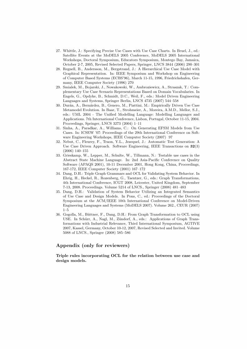
Appendix (only for reviewers)
Triple rules incorporating OCL for the relation between use case anddesign models.
15
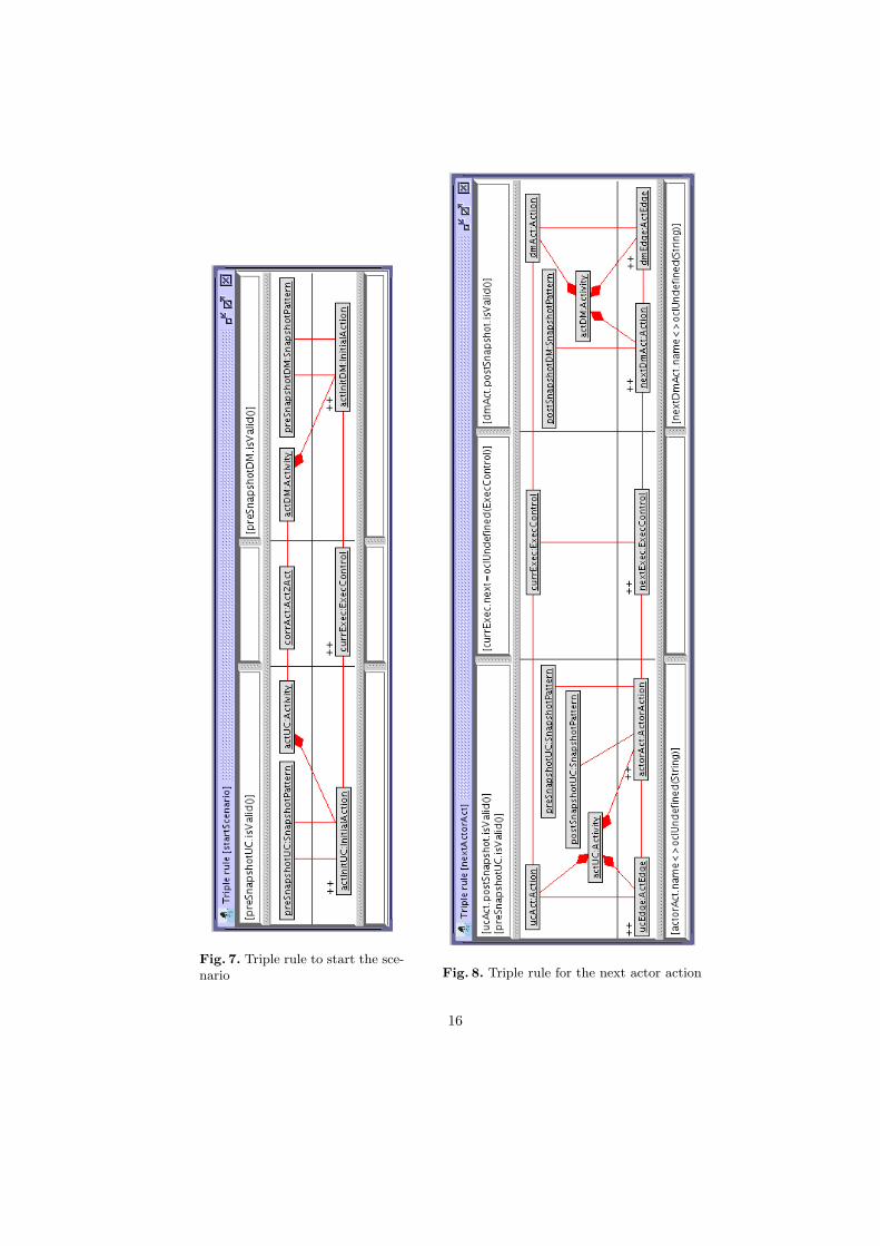
Fig. 7. Triple rule to start the sce-nario Fig. 8. Triple rule for the next actor action
16
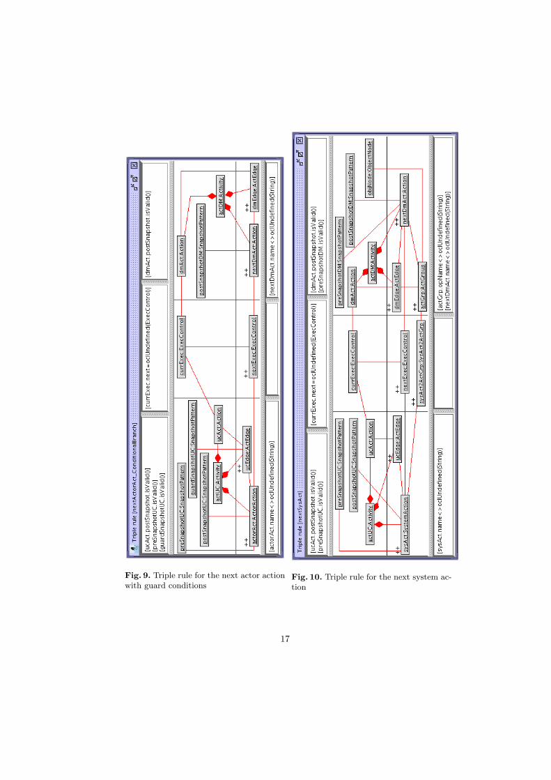
Fig. 9. Triple rule for the next actor actionwith guard conditions
Fig. 10. Triple rule for the next system ac-tion
17

Fig. 11. Triple rule for the next action atthe design level
Fig. 12. Triple rule for the next action withguard conditions at the design level
18
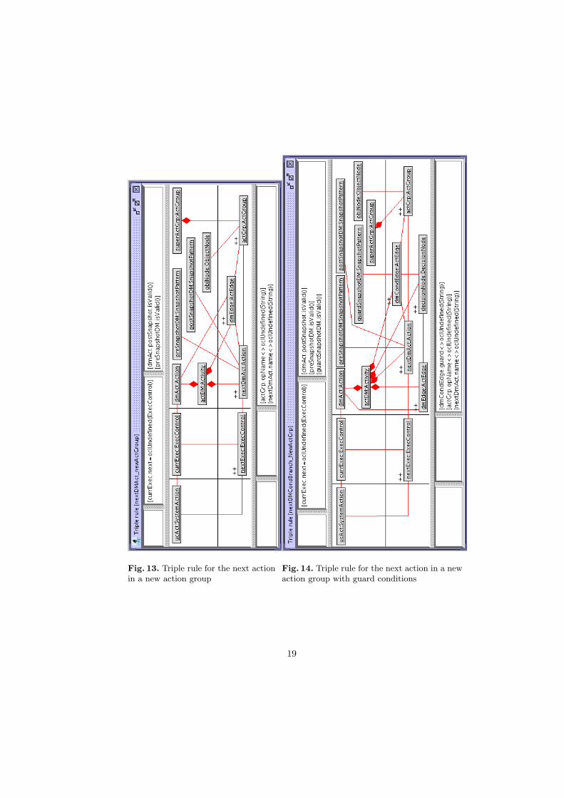
Fig. 13. Triple rule for the next actionin a new action group
Fig. 14. Triple rule for the next action in a newaction group with guard conditions
19
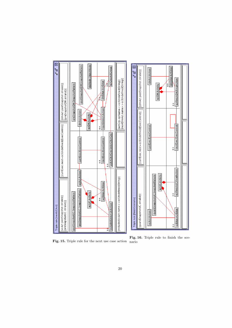
Fig. 15. Triple rule for the next use case actionFig. 16. Triple rule to finish the sce-nario
20