oil fired furnace - dettson...oil fired furnace upflow printed in canada printed on 100% recycled...
TRANSCRIPT
OIL FIRED FURNACEUPFLOW
Printed in CanadaPrinted on 100% recycled paper
Caution: Do not tamper with the unit or its controls.Call a qualified servicetechnician.
2008-08-11 X40054 Rev. X
Models :
FLO115DABR-CLBO125DABR13-DLBO145DABR34-DMBO115DABR-DMBOV115DABR-DOLF140C12COLR182A16CDNS-0594 Rév. A
DNS-0665 Rév. A
DNS-0575 Rév. A
Manufactured by:
UTC Canada CorporationICP Division3400 Industrial BoulevardSherbrooke, Quebec - CanadaJ1L 1V8
INSTALLER / SERVICE TECHNICIAN: USE THE INFORMATION IN THIS MANUAL FOR THE INSTALLATION AND SERVICING OF THE UNIT. KEEP THE DOCUMENT NEAR THE FURNACE FOR FUTURE REFERENCE.
HOMEOWNER:PLEASE KEEP THIS MANUAL NEAR THE FURNACE FOR FUTURE REFERENCE.
PART 1 INSTALLATION
3
SAFETY CONSIDERATIONS INSTALLATION OF OIL FIRED HEATING UNITS SHALL BE IN STRICT ACCORDANCE WITH THE REGULATIONS OF THE AUTHORITIES HAVING JURISDICTION. IN CANADA CSA B139 AND IN THE UNITED STATES NFPA NO.31-1992 INSTALLATION CODES FOR OIL BURNING EQUIPMENT APPLY. DO NOT OPERATE FURNACE IN A CORROSIVE ATMOSPHERE CONTAINING CHLORINE, FLUORINE OR ANY OTHER DAMAGING CHEMICALS. DO NOT STORE OR USE GASOLINE, OR OTHER FLAMMABLE VAPOURS AND LIQUIDS IN THE VICINITY OF THIS OR ANY OTHER APPLIANCE. 1.1) SAFETY LABELING AND WARNING SIGNS DANGER, WARNING AND CAUTION The words DANGER, WARNING and CAUTION are used to identify the levels of seriousness of certain hazards. It is important that you understand their meaning. You will notice these words in the manual as follows:
DANGER
Immediate hazards that WILL result in death or serious damage to body and/or property.
WARNING Hazards or unsafe practices that CAN result in death or damage to body and/or property.
CAUTION Hazards or unsafe practices which CAN result in damage to body and/or property.
1.2) SAFE INSTALLATION REQUIREMENTS
WARNING Installation or repairs performed by unqualified persons can result in hazards to them and others. Installation MUST conform to local codes or, in the absence of same, to codes of the country having jurisdiction.
The information contained in this manual is intended for use by a qualified service technician familiar with safety procedures and equipped with the proper tools and test instruments.
Failure to carefully read and follow all instructions in this manual can result in death and/or personal injury, property damage, furnace malfunction.
WARNING Fire hazard
The furnace must be installed in a level position, never where it will slope toward the front. If the furnace is installed in the latter position, oil will drain into the furnace vestibule and create a fire hazard. NOTE: It is the personal responsibility and obligation of the homeowner to contact a qualified technician to ensure that the installation conforms to applicable local and/or national codes and ordinances. a. This furnace is NOT approved for installation in mobile homes,
trailers or recreational vehicles; b. Do NOT use this furnace as a construction heater or to heat a
building under construction; c. There must be a sufficient supply of fresh air for combustion as
well as ventilation in the area where the furnace is located; d. Use only the Type of fuel oil approved for this furnace (see
Rating Plate on unit). Overfiring will result in heat exchanger failure and cause dangerous operating conditions;
e. Visually check all oil line joints for signs of wetness, which would indicate a leak;
f. Connect furnace to the chimney; g. The points in Part 2 “Operation” are vital to the proper and safe
operation of the heating system. Take the time to ensure that all steps were followed;
h. Follow the regulations of the ANSI/NFPA No.31 (in the USA) and CSA B-139 (in Canada) or local codes for placing and installing the oil storage tank;
i. Follow a regular service and maintenance schedule for the most efficient and safe operation of the furnace.
4
j. Before servicing, allow furnace to cool. Always shut off electricity and fuel to the furnace when servicing. This will prevent electrical shock or burns;
k. Seal supply and return air ducts; l. The vent system MUST be checked to determine that it is the
correct type and size; m. Install correct filter type and size; n. Unit MUST be installed so that electrical components are
protected from direct contact with water. 1.2.1) Safety Rules Your unit is built to provide many years of safe and dependable service, providing it is properly installed and maintained. However, abuse and/or improper use can shorten the life of the unit and create hazards for you, the owner. a. The U.S. Consumer Product Safety Commission recommends
that users of oil or gas-burning appliances install carbon monoxide detectors. Carbon monoxide can cause serious injury and/or death. Therefore, to help alert people of potentially dangerous carbon monoxide levels, you should have carbon monoxide detectors, listed by a nationally recognized agency (e.g. Underwriters Laboratories or International Approval Services) and maintained in the building or dwelling (see Note below).
b. There can be numerous sources of fire or smoke in a building or
dwelling. Fire or smoke can cause death, serious bodily injury and/or property damage. Therefore, in order to alert people of potentially dangerous fire or smoke, you should have fire and smoke detectors installed (listed by Underwriters Laboratories) and maintained in the building or dwelling (see Note below).
NOTE: The manufacturer of your furnace does not test any detectors
and makes no representations regarding any brand or type of detector.
CAUTION Ensure that the area around the combustion air intake terminal is free of snow, ice and debris.
CAUTION Do not use any commercially available soot remover. This furnace has a fibre type refractory combustion chamber. Normal servicing of this unit does not require cleaning of the combustion chamber. Use extreme care if for any reason you have to work in the area of the combustion chamber.
1.2.2) Freezing temperatures and your building
WARNING
Freezing temperature warning.
Turn off water supply.
If your heater remains shut off during cold weather the water pipes could freeze and burst, resulting in serious water damage. Your unit is equipped with safety devices that may keep it from operating if sensors detect abnormal conditions such as clogged exhaust flues. If the structure is unattended during cold weather you should take the following precautions: a. Turn off main water supply into the structure and drain the water
lines if possible. Open faucets in appropriate areas; b. Have someone check the structure frequently during cold
weather to make sure it is warm enough to prevent pipes from freezing. Contact a qualified service agency, if required.
1.2.3) Installation regulations All local and national code requirements governing the installation of oil burning equipment, wiring and flue connections MUST be followed. Some of the codes that may be applicable are: CSA B139 Installation code for oil burning equipment NFPA 31 Installation of oil burning equipment ANSI/NFPA 90B Warm air heating and air conditioning systems ANSI/NFPA 70 National electrical code CSA C22.2 Nr. 3 Canadian electrical code Only the latest issues of the above codes should be used. 1.3) POSITIONING THE FURNACE
CAUTION Carefully check your furnace upon delivery for any evidence of damage that may have occurred during shipping and handling. Any claims for damages or lost parts must be made with the Transport Company. This furnace is approved for reduced clearances to combustible construction. Therefore, it may be installed in a closet or similar enclosure. In any case, the unit must always be installed level. In a basement, or when installed on the floor (as in a crawlspace), it is recommended that the unit be installed on a concrete pad that is 2.54 cm to 5.08 cm (1" to 2") thick. The unit must be installed in a location where the ambient and return air temperatures are above 15°C (60°F).
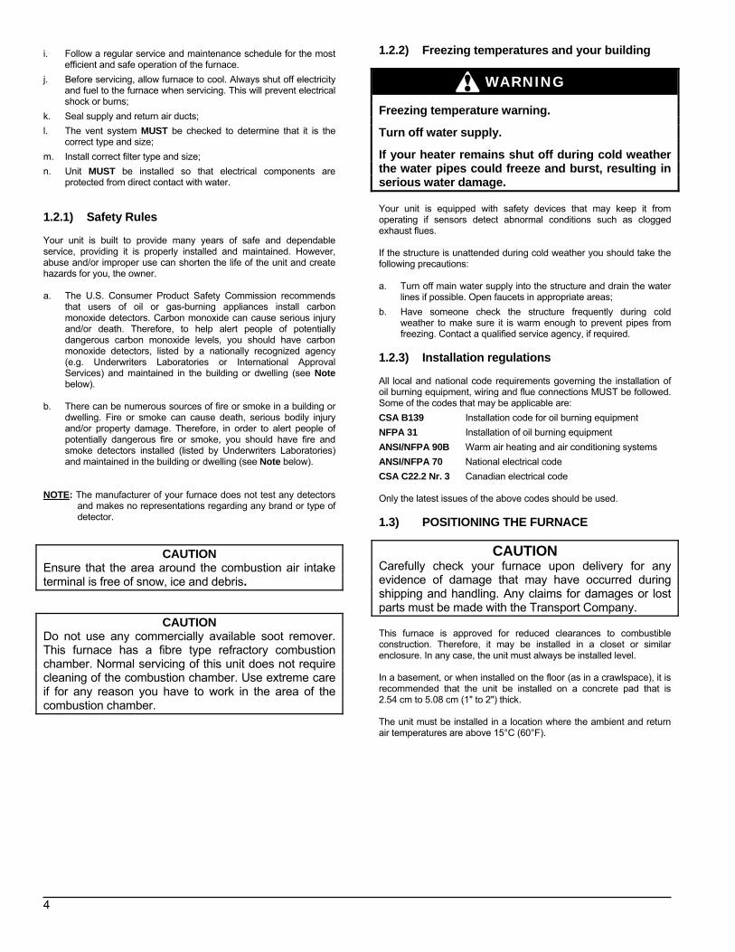
1.3.1) Installation of the filter rack When you install your furnace, the filter rack opening can be installed on either side (right or left) for air filter maintenance.
5
FIGURE 1 The required minimum clearances for this furnace are specified in Table 1. The furnace should be positioned as closely as possible to the chimney to keep vent connections short and direct. It should also be as close as possible to the centre of the air distribution system.
CAUTION Do NOT operate furnace in a corrosive atmosphere containing chlorine, fluorine or any other damaging chemicals. Refer to Part 1, section 5.2 (1.5.2).
WARNING
Electrical shock hazard.
This furnace is not watertight and is not designed for outdoor installation. This furnace shall be installed in such a manner as to protect the electrical components from water.
Outdoor installation will lead to a hazardous electrical condition, premature furnace failure, property damage, injury or death.
1.4) VENTING
WARNING
Poisonous carbon monoxide gas, fire and explosion hazard.
Read and follow all instructions in this section.
Failure to properly vent this furnace can result in property damage, injury or death.
CAUTION When the furnace is chimney vented together with other combustion appliances such as a water heater, the allowable venting materials for use with those appliances must be investigated (“L”-Vent, etc.). These oil furnaces are certified for use with "L" vent, "A" vent, tile-lined and metal-liner-tile-lined chimneys. The appliance may be connected to a chimney of proper size and adequate chimney base temperature, as specified in the Installation Code. The relevant excerpt from the code is found in this section. Use it as a guide when local or national codes do not exist.
DNS-0678 Rev. B
Flue pipe sizing The following table is an excerpt from the installation code that indicates permitted flue sizes and minimum base temperatures for circular flues in chimneys with a thermal resistance of less than R6 (6 ft2 •hr •°F / Btu). Where a new appliance, burner, or chimney is installed, chimney vent sizes and maximum flue-gas temperatures shall comply with Table 2, p. 6. Measurements must be taken at the chimney connector, after 5 minutes of operation with the barometric damper shut.
WARNING
Poisonous carbon monoxide gas hazard.
Never install a hand operated damper in the vent pipe. However, any Underwriters Laboratories listed electrically operated automatic type vent damper may be installed if desired. Be sure to follow the instructions provided with vent damper. Also, read and follow all instructions in this section of the manual.
Failure to properly vent this furnace or other appliances can result in death or personal injury, property damage.
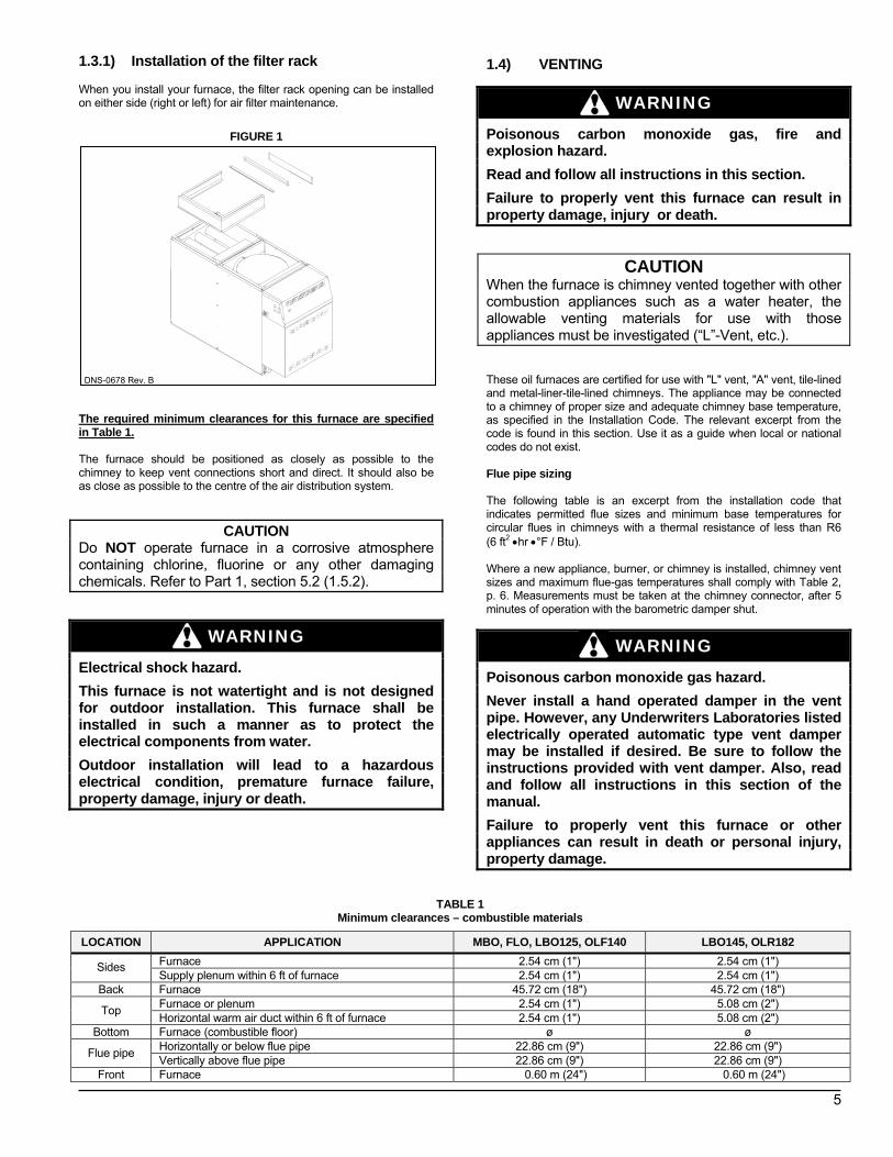
TABLE 1 Minimum clearances – combustible materials
LOCATION APPLICATION MBO, FLO, LBO125, OLF140 LBO145, OLR182 Furnace 2.54 cm (1") 2.54 cm (1") Sides Supply plenum within 6 ft of furnace 2.54 cm (1") 2.54 cm (1")
Back Furnace 45.72 cm (18") 45.72 cm (18") Furnace or plenum 2.54 cm (1") 5.08 cm (2") Top Horizontal warm air duct within 6 ft of furnace 2.54 cm (1") 5.08 cm (2")
Bottom Furnace (combustible floor) ø ø Horizontally or below flue pipe 22.86 cm (9") 22.86 cm (9") Flue pipe Vertically above flue pipe 22.86 cm (9") 22.86 cm (9")
Front Furnace 0.60 m (24") 0.60 m (24")
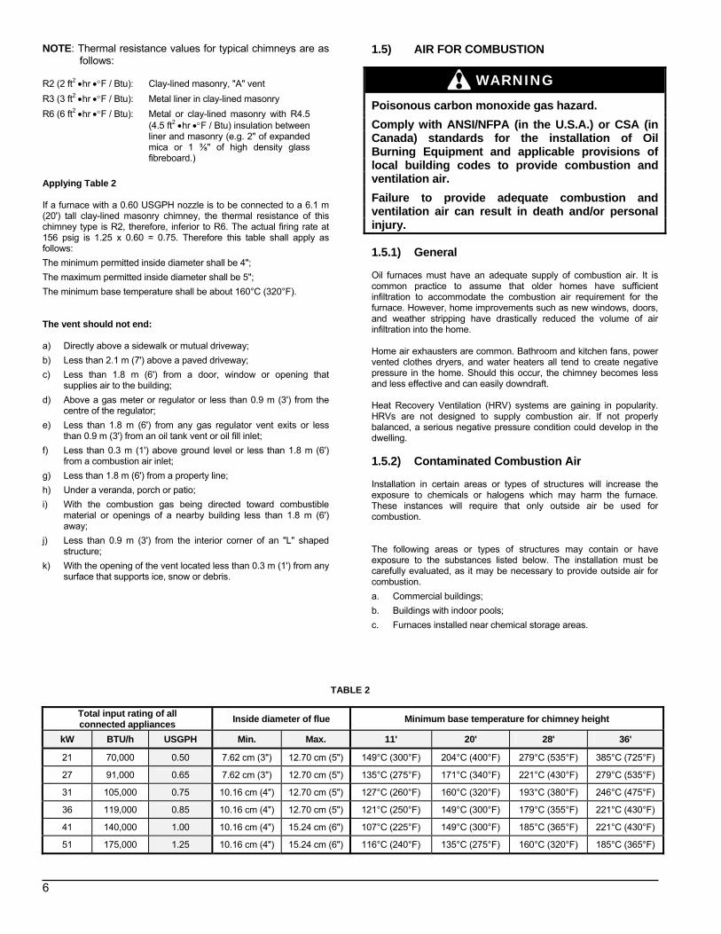
NOTE: Thermal resistance values for typical chimneys are as follows:
6
R2 (2 ft2 •hr •°F / Btu): Clay-lined masonry, "A" vent R3 (3 ft2 •hr •°F / Btu): Metal liner in clay-lined masonry R6 (6 ft2 •hr •°F / Btu): Metal or clay-lined masonry with R4.5
(4.5 ft2 •hr •°F / Btu) insulation between liner and masonry (e.g. 2" of expanded mica or 1 ⅜" of high density glass fibreboard.)
Applying Table 2 If a furnace with a 0.60 USGPH nozzle is to be connected to a 6.1 m (20') tall clay-lined masonry chimney, the thermal resistance of this chimney type is R2, therefore, inferior to R6. The actual firing rate at 156 psig is 1.25 x 0.60 = 0.75. Therefore this table shall apply as follows: The minimum permitted inside diameter shall be 4"; The maximum permitted inside diameter shall be 5"; The minimum base temperature shall be about 160°C (320°F). The vent should not end: a) Directly above a sidewalk or mutual driveway; b) Less than 2.1 m (7') above a paved driveway; c) Less than 1.8 m (6') from a door, window or opening that
supplies air to the building; d) Above a gas meter or regulator or less than 0.9 m (3') from the
centre of the regulator; e) Less than 1.8 m (6') from any gas regulator vent exits or less
than 0.9 m (3') from an oil tank vent or oil fill inlet; f) Less than 0.3 m (1') above ground level or less than 1.8 m (6')
from a combustion air inlet; g) Less than 1.8 m (6') from a property line; h) Under a veranda, porch or patio; i) With the combustion gas being directed toward combustible
material or openings of a nearby building less than 1.8 m (6') away;
j) Less than 0.9 m (3') from the interior corner of an "L" shaped structure;
k) With the opening of the vent located less than 0.3 m (1') from any surface that supports ice, snow or debris.
1.5) AIR FOR COMBUSTION
WARNING
Poisonous carbon monoxide gas hazard.
Comply with ANSI/NFPA (in the U.S.A.) or CSA (in Canada) standards for the installation of Oil Burning Equipment and applicable provisions of local building codes to provide combustion and ventilation air.
Failure to provide adequate combustion and ventilation air can result in death and/or personal injury. 1.5.1) General Oil furnaces must have an adequate supply of combustion air. It is common practice to assume that older homes have sufficient infiltration to accommodate the combustion air requirement for the furnace. However, home improvements such as new windows, doors, and weather stripping have drastically reduced the volume of air infiltration into the home. Home air exhausters are common. Bathroom and kitchen fans, power vented clothes dryers, and water heaters all tend to create negative pressure in the home. Should this occur, the chimney becomes less and less effective and can easily downdraft. Heat Recovery Ventilation (HRV) systems are gaining in popularity. HRVs are not designed to supply combustion air. If not properly balanced, a serious negative pressure condition could develop in the dwelling. 1.5.2) Contaminated Combustion Air Installation in certain areas or types of structures will increase the exposure to chemicals or halogens which may harm the furnace. These instances will require that only outside air be used for combustion. The following areas or types of structures may contain or have exposure to the substances listed below. The installation must be carefully evaluated, as it may be necessary to provide outside air for combustion. a. Commercial buildings; b. Buildings with indoor pools; c. Furnaces installed near chemical storage areas.
TABLE 2
Total input rating of all connected appliances Inside diameter of flue Minimum base temperature for chimney height
kW BTU/h USGPH Min. Max. 11' 20' 28' 36'
21 70,000 0.50 7.62 cm (3") 12.70 cm (5") 149°C (300°F) 204°C (400°F) 279°C (535°F) 385°C (725°F)
27 91,000 0.65 7.62 cm (3") 12.70 cm (5") 135°C (275°F) 171°C (340°F) 221°C (430°F) 279°C (535°F)
31 105,000 0.75 10.16 cm (4") 12.70 cm (5") 127°C (260°F) 160°C (320°F) 193°C (380°F) 246°C (475°F)
36 119,000 0.85 10.16 cm (4") 12.70 cm (5") 121°C (250°F) 149°C (300°F) 179°C (355°F) 221°C (430°F)
41 140,000 1.00 10.16 cm (4") 15.24 cm (6") 107°C (225°F) 149°C (300°F) 185°C (365°F) 221°C (430°F)
51 175,000 1.25 10.16 cm (4") 15.24 cm (6") 116°C (240°F) 135°C (275°F) 160°C (320°F) 185°C (365°F)
Exposure to these substances: a. Permanent wave chemicals for hair; b. Chlorinated waxes and cleaners; c. Chlorine based swimming pool chemicals; d. Water softening chemicals; e. De-icing salts or chemicals; f. Carbon tetrachloride; g. Halogen type refrigerants;
7
h. Cleaning solvents (such as perchloroethylene); i. Printing inks, paint removers, varnishes, etc.; j. Hydrochloric acid; k. Solvent based glue; l. Antistatic fabric softeners for clothes dryers; m. Acid based masonry cleaning materials. 1.5.3) Ducted outdoor combustion air Outdoor combustion air kit – chimney venting
The following kits have been certified for use with the appliance. The component kits contain an important safety feature, namely a Vacuum Relief Valve or VRV. During normal operation the burner aspirates outdoor air. If the intake terminal ever becomes partially or fully blocked from ice or snow etc., the VRV will open to allow a proportion of air from the dwelling to enter the burner, thus maintaining proper combustion. Once the blockage is removed, the VRV will close and the burner will draw all the air from the outside again: CAS-2B Components for the Beckett AFG burner (except air duct): The kit includes the intake terminal, vacuum relief valve (VRV) and special air boot connection with integral air adjustment means for the AFG burner. The CAS-2B can be used with a 10 cm (4") galvanized air duct or a 10 cm (4") flexible aluminium air duct. It is recommended that the metallic air ducting material be insulated from the air intake up to 1.5 m (5') from the burner to avoid condensation from forming on the outside of the intake pipe. CAD-1 Air duct kit consists of 7.6 m (25') of insulated UL/ULC Listed Class 1 air duct, and two 10 cm (4") steel band clamps. The duct incorporates a corrugated flexible aluminium core, surrounded by fibreglass insulation covered with a vinyl vapour barrier.
CAUTION The CAS-2B does not turn the furnace installation into a direct vent system. Therefore the building structure must provide for adequate combustion air to be delivered to the Vacuum Relief Valve. The burner will need to draw combustion air from the VRV’s surroundings if the intake ever becomes blocked. Therefore, non-direct vent installation codes must be followed. Comprehensive installation instructions are provided with the kits. 1.6) OIL TANKS AND LINES Check your local codes for the installation of the tank and accessories. A manual shut-off valve and an oil filter shall be installed in sequence from tank to burner. Be sure that the oil line is clean before connecting to the burner. The oil line should be protected to eliminate any possible damage. Installations where the fuel oil tank is below the burner level must employ a two pipe fuel supply system with an appropriate fuel pump. A rise of more than 2.4 m (8') requires a 2 stage pump and more than 4.9 m (16') an auxiliary pump.
Follow the pump instructions to determine the size of tubing you need in relation to the rise, or to the horizontal distance.
Inspect the entire oil distribution system for leaks at the beginning of each annual heating season. 1.7) BURNER INSTALLATION
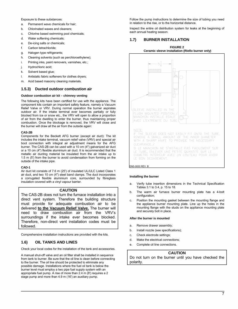
FIGURE 2
Ceramic sleeve installation (Riello burner only)
DNS-0830 REV. B
Installing the burner a. Verify tube insertion dimensions in the Technical Specification
Tables 3.1 to 3.4, p. 15 to 18. b. The warm air furnace burner mounting plate has a 4-bolt
configuration; c. Position the mounting gasket between the mounting flange and
the appliance burner mounting plate. Line up the holes in the mounting flange with the studs on the appliance mounting plate and securely bolt in place.
After the burner is mounted a. Remove drawer assembly; b. Install nozzle (see specifications); c. Check electrode settings; d. Make the electrical connections; e. Complete oil line connections.
CAUTION Do not turn on the burner until you have checked the polarity.
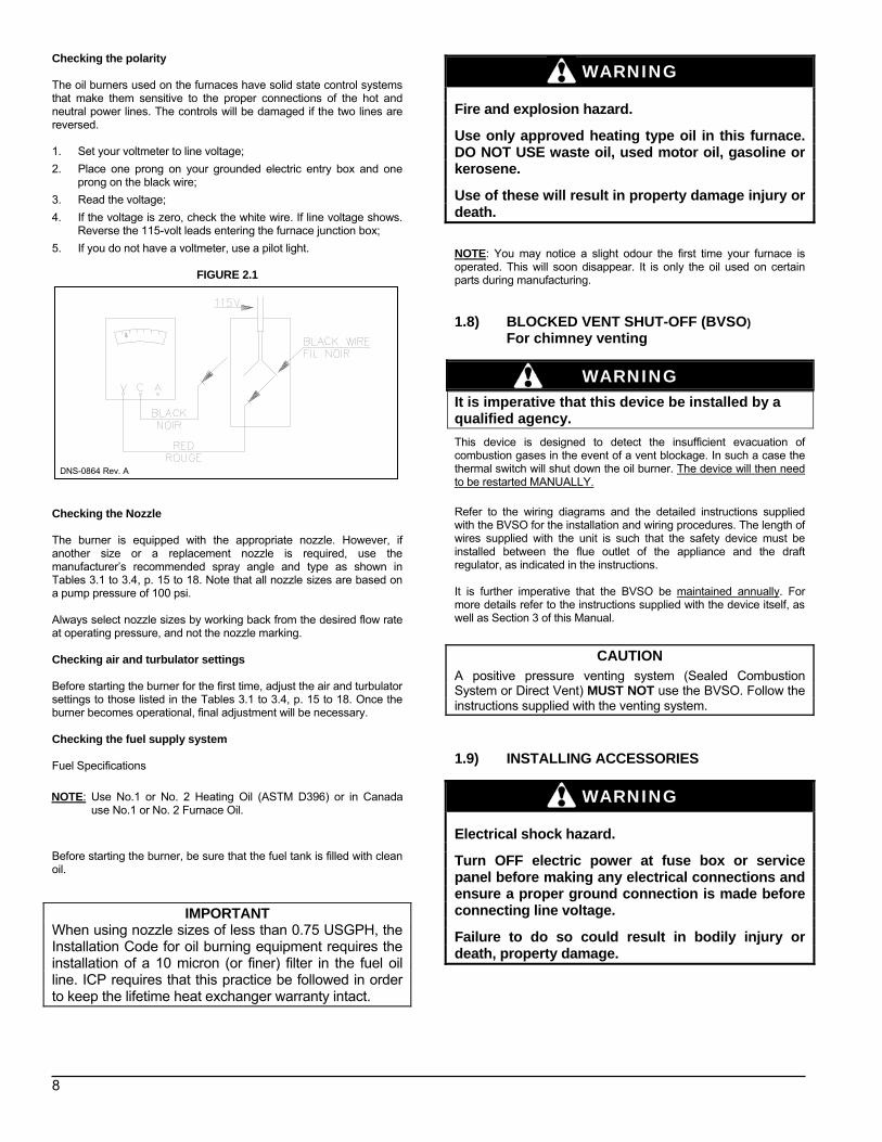
Checking the polarity
8
The oil burners used on the furnaces have solid state control systems that make them sensitive to the proper connections of the hot and neutral power lines. The controls will be damaged if the two lines are reversed. 1. Set your voltmeter to line voltage; 2. Place one prong on your grounded electric entry box and one
prong on the black wire; 3. Read the voltage; 4. If the voltage is zero, check the white wire. If line voltage shows.
Reverse the 115-volt leads entering the furnace junction box; 5. If you do not have a voltmeter, use a pilot light.
FIGURE 2.1
Checking the Nozzle The burner is equipped with the appropriate nozzle. However, if another size or a replacement nozzle is required, use the manufacturer’s recommended spray angle and type as shown in Tables 3.1 to 3.4, p. 15 to 18. Note that all nozzle sizes are based on a pump pressure of 100 psi. Always select nozzle sizes by working back from the desired flow rate at operating pressure, and not the nozzle marking. Checking air and turbulator settings Before starting the burner for the first time, adjust the air and turbulator settings to those listed in the Tables 3.1 to 3.4, p. 15 to 18. Once the burner becomes operational, final adjustment will be necessary. Checking the fuel supply system Fuel Specifications
Before starting the burner, be sure that the fuel tank is filled with clean oil.
IMPORTANT When using nozzle sizes of less than 0.75 USGPH, the Installation Code for oil burning equipment requires the installation of a 10 micron (or finer) filter in the fuel oil line. ICP requires that this practice be followed in order to keep the lifetime heat exchanger warranty intact.
WARNING Fire and explosion hazard.
Use only approved heating type oil in this furnace. DO NOT USE waste oil, used motor oil, gasoline or kerosene.
Use of these will result in property damage injury or death. NOTE: You may notice a slight odour the first time your furnace is operated. This will soon disappear. It is only the oil used on certain parts during manufacturing. 1.8) BLOCKED VENT SHUT-OFF (BVSO)
For chimney venting
WARNING It is imperative that this device be installed by a qualified agency.
This device is designed to detect the insufficient evacuation of combustion gases in the event of a vent blockage. In such a case the thermal switch will shut down the oil burner. The device will then need to be restarted MANUALLY. Refer to the wiring diagrams and the detailed instructions supplied with the BVSO for the installation and wiring procedures. The length of wires supplied with the unit is such that the safety device must be installed between the flue outlet of the appliance and the draft regulator, as indicated in the instructions. It is further imperative that the BVSO be maintained annually. For more details refer to the instructions supplied with the device itself, as well as Section 3 of this Manual.
CAUTION A positive pressure venting system (Sealed Combustion System or Direct Vent) MUST NOT use the BVSO. Follow the instructions supplied with the venting system. 1.9) INSTALLING ACCESSORIES
WARNING Electrical shock hazard.
Turn OFF electric power at fuse box or service panel before making any electrical connections and ensure a proper ground connection is made before connecting line voltage.
Failure to do so could result in bodily injury or death, property damage.
DNS-0864 Rev. A
NOTE: Use No.1 or No. 2 Heating Oil (ASTM D396) or in Canada use No.1 or No. 2 Furnace Oil.
1.9.1) Air conditioning
9
An air conditioning coil may be installed on the supply air side only. Also, notwithstanding the evaporator coil manufacturer’s instructions, a minimum clearance of 15 cm (6") must be allowed between the bottom of the coil drain pan, and the top of the heat exchanger. Wire the thermostat and condensing unit contactor as indicated in the wiring diagram in Figure 5, p. 21. 1.9.2) Ductwork and Filter Installation Design and install the air distribution system to comply with Air Conditioning Contractors of America manuals or other approved methods that conform to local codes and good trade practices. When ducting supplies air to a space other than where the furnace is located, the return-air ducts must be sealed and also be directed to the space other than where the furnace is located. Install the air conditioning cooling coil (evaporator) downstream from the supply air plenum of the furnace. If a separate evaporator and blower unit is used, install appropriate sealing dampers for air flow control. Cold air from the evaporator coil going through the furnace could cause condensation and shorten furnace life.
CAUTION
Dampers (purchased locally) MUST be automatic.
WARNING Poisonous carbon monoxide gas hazard.
Do NOT draw return air from inside a closet or utility room. Return air duct MUST be sealed to furnace casing.
Failure to properly seal ducts can result in death, personal injury and/or property damage.
WARNING Poisonous carbon monoxide gas hazard.
Install evaporator coil on the supply side of the furnace ducting.
Evaporator coil installed in return side ducting can cause condensation to form inside heat exchanger resulting in heat exchanger failure. This could result in death, personal injury and/or property damage.
PART 2 OPERATION
2.1) SEQUENCE OF OPERATION
10
2.1.1) Sequence of operation
Beckett AFG, Riello 40-F and Aero F-FAC 1. Normally open contact (T-T) on primary relay closed when
thermostat calls for heat; 2. AFG and F-FAC burner: The motor starts and spark is
established. The pump pressure builds and the oil supply mechanism opens, admitting fuel to the nozzle;
3. R40-F Burner: The burner motor starts. The burner motor fan pre-purges the combustion chamber and vent for 10 seconds, establishing the combustion air pattern. During this time the solenoid valve holding coil pressure is approximately 100 psig. The solenoid valve opens, allowing oil to flow through the nozzle. At the same time, the burner motor ignition coil produces a spark;
4. Spark ignites oil droplets; 5. Cad cell senses flame and burner continues to fire. Ignition
transformer ceases sparking (Riello R40-F); 6. After Fan-Limit control heats up to the factory set point, the
circulating air blower and electronic air cleaner start; 7. The circulating air blower and burner motor remain on until the
thermostat is satisfied. The ignition transformer continues to spark (AFG). The solenoid valve remains open (R40-F);
Thermostat is satisfied: 8. Primary relay contacts open, solenoid valve closes (R40-F),
burner fan motor shuts down. The ignition transformer ceases sparking (AFG);
9. The Fan-Limit control bi-metal cools down to the factory set point of 32°C (90°F), the circulating air blower and the electronic air cleaner turn off.
2.2) CHECKS AND ADJUSTMENTS 2.2.1) General After initial installation and subsequent yearly maintenance calls, the furnace must be thoroughly tested.
IMPORTANT The burner must be functioning for at least 10 minutes before any test readings are taken. Adjustments are to be made according to the Technical Specifications in this manual. Open the oil bleed port screw and start the burner. Allow the oil to drain into a container for at least 10 seconds. Once the oil flows absolutely free of white streaks or air bubbles to indicate that no air is being drawn into the suction side of the oil piping and pump, slowly close and tighten the bleed screw. The burner should now fire. Adjust the oil pressure as indicated in the Technical Specification Tables 3.1 to 3.4, p. 15 to 18. 2.2.2) Restart after burner failure 1. Set thermostat lower than the room temperature; 2. Press the reset button on the burner primary control (relay); 3. Set thermostat higher than the room temperature; 4. If the burner motor does not start or ignition fails, turn off the
disconnect switch and CALL A QUALIFIED SERVICE TECHNICIAN.
CAUTION Do not attempt to start the burner when excess oil has accumulated, when the furnace is full of vapour, or when the combustion chamber is very hot. 2.2.3) BVSO Performance Test The purpose of the following test is to check that the electrical outlet on the furnace, designated to the BVSO, is functional.
1. Start up the burner; 2. Remove the three-pole plug from the BVSO outlet on the
furnace; 3. The burner must shut-off immediately, while the blower continues
to run to the end of the cool-down cycle.
If the test is not in line with the above, CALL A QUALIFIED SERVICE TECHNICIAN. 2.2.4) Combustion chamber curing Some moisture and binders remain in the ceramic combustion chamber after manufacture. It is important to clear the chamber of this residue before testing. If you smoke test before curing, the instrument may become damaged. To cure the chamber, run the unit for 3 consecutive cycles, with 3 minutes of elapsed time in between each cycle. Each burn cycle should least 3 minutes. The exhaust will have a pungent odour and produce a white cloud of steam. 2.2.5) Smoke / CO2 test 1. Pierce a test hole in the smoke pipe near the furnace breech.
Insert the smoke test instrument probe into the open hole; 2. Starting with a zero smoke reading, gradually reduce the burner
air setting until just a trace of smoke results (#1 on Bacharach Scale);
3. Take a CO2 sample at the same test location where the smoke sample was taken. Note the CO2 reading associated with the #1 smoke condition;
4. Adjust the burner air setting to obtain a CO2 reading 1% lower than the reading associated with the #1 smoke;
5. This method of adjusting the CO2 will allow adequate excess air to ensure that the burner will burn clean for the entire heating season.
2.2.6) Supply air temperature rise test 1. Operate the burner for at least 10 minutes; 2. Measure the air temperature in the return air plenum; 3. Measure the air temperature in the largest trunk coming off the
supply air plenum, just outside the range of radiant heat coming off the heat exchanger; 0.3 m (12") from the plenum on the main take-off usually sufficient;
4. The temperature rise is calculated by subtracting the return air temperature from the supply air temperature;
5. If the temperature rise exceeds the temperature specified in Tables 3.1 to 3.4, p. 15 to 18, change to the next higher blower speed tap until the temperature rise falls to this temperature or below. If the excessive temperature rise cannot be reduced by increasing fan speed, investigate for ductwork restriction(s), dirty or improper air filter, overfiring caused by excessive pump pressure, or improper nozzle sizing.
11
2.2.7) Vent temperature test 1. Place a thermometer in the test hole located in the breech pipe. 2. The vent temperature should be between 204°C to 302°C
(400°F to 575°F). If not, check for improper air temperature rise, pump pressure, nozzle size, or for a badly sooted heat exchanger.
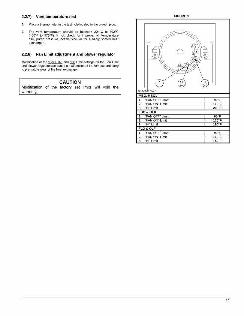
2.2.8) Fan Limit adjustment and blower regulator Modification of the “FAN ON” and “HI” Limit settings on the Fan Limit and blower regulator can cause a malfunction of the furnace and carry to premature wear of the heat exchanger.
CAUTION Modification of the factory set limits will void the warranty.
FIGURE 3
DNS-0355 Rev.B
MBO, MBOV 1 “FAN OFF” Limit 90°F 2 “FAN ON” Limit 110°F 3 “HI” Limit 200°F LBO & OLR 1 “FAN OFF” Limit 90°F 2 “FAN ON” Limit 130°F 3 “HI” Limit 190°F FLO & OLF 1 “FAN OFF” Limit 90°F 2 “FAN ON” Limit 110°F 3 “HI” Limit 150°F
PART 3
MAINTENANCE
3.1) GENERAL Preventive Maintenance “Preventive maintenance” is the best way to avoid unnecessary expense and inconvenience. Have your heating system and burner inspected at regular intervals by a qualified service technician. After each annual inspection a complete combustion test must be performed, in order to maintain optimum performance and reliability.
12
WARNING Electrical shock hazard.
Turn OFF power to furnace before any disassembly or servicing.
Failure to do so can result in property damage injury and/or death. Do not tamper with the unit or controls. Call a qualified service technician. Before calling for service, check the following : a. Check oil tank gauge and check if the oil tank valve in oil is open; b. Check fuse or circuit breaker; c. Check if shut-off switch is “ON”; d. Reset thermostat above room temperature; e. If ignition does not occur turn off the disconnect switch and call a
qualified service technician. When ordering replacement parts, specify the complete furnace model number and serial number. 3.1.1) Heat exchanger cleaning Ordinarily, it is not necessary to clean the heat exchanger or flue pipe every year, but it is advisable to have your oil burner serviceman check the unit before each heating season to determine whether cleaning or replacement of parts is necessary. If cleaning is necessary, the following steps should be performed: 1. Turn “OFF” all utilities upstream of the furnace; 2. Disconnect the flue pipe; 3. Remove the flue collar panel located at the rear part of the warm
air furnace; 4. Remove the radiator baffles; 5. Disconnect the oil line and remove the oil burner from the
furnace; 6. Clean the secondary tubes, and the primary cylinder with a stiff
brush and vacuum cleaner; 7. The heat exchanger and combustion chamber should be
inspected to determine if replacement is required before re-assembling the unit;
8. After cleaning, replace the radiator baffles, flue collar plate and oil burner;
9. Readjust burner for proper operation.
Soot will have collected in the first sections of the heat exchangers only if the burner was started after the combustion chamber was flooded with fuel oil, or if the burner has been operating in a severely contaminated condition. 3.1.2) Refractory firepot Remove the burner and check the firepot.
IMPORTANT Use extreme care if cleaning of the pot is required. After firing, the pot becomes very fragile. Do not use any commercially available soot remover. This furnace has a fibre type refractory combustion chamber. Normal servicing of this unit does not require cleaning of the combustion chamber.
IMPORTANT Do not vacuum the ceramic chambers—they are easily damaged. If the pot is damaged, it must be replaced. A damaged pot could lead to premature heat exchanger failure. Cracking of the firepot is normal, however, replace the pot only if the cracks have propagated more than ⅔ the way through the wall thickness. The average wall thickness of the firepot is ¾". Flooding of the firepot Flooding can occur when the oil primary control has been reset a number of times in a no-heat situation. Each time oil is fired into the pot and does not ignite, it is absorbed into the pot. Even if the burner is removed and the pot is felt for wetness, it is difficult to assess the degree of oil absorption by the pot. There is only one way to properly service a flooded firepot, and that is to change it.
CAUTION If you observe the red warning light on the burner, push once ONLY to try and restart. If the burner will not start, phone an authorized service technician. Do not press the button again.
13
3.1.3) BLOCKED VENT SHUT-OFF (BVSO) CLEANING
For continued safe operation, the Blocked Vent Shut-Off System (BVSO) is required to be inspected and maintained annually by a qualified agency. 1. Disconnect the power to the appliance; 2. Remove the two screws holding on the BVSO assembly cover; 3. Remove the cover; 4. Remove the two screws holding the control box to the heat
transfer tube assembly. Sliding the control box in the appropriate direction will unlock it from the heat transfer tube assembly;
5. Carefully remove any build-up from the thermal switch surface;
CAUTION Do not dent or scratch the surface of the thermal switch. If the thermal switch is damaged, replacement is required. 6. Clear and remove any build-up or obstruction inside the heat
transfer tube; 7. Re-mount, lock and fasten the control box with the 2 screws
removed in step 4; 8. Re-attach the assembly cover with the screws removed in step 2; 9. Re-establish power to the appliance.
3.1.4) Burner drawer assembly Remove the drawer assembly. Clean all foreign matter from the retention head and electrodes. If a Beckett AFG burner was installed, the burner will have to be removed to check the retention head. 3.1.5) Nozzle Replace the nozzle with the one specified in Tables 3.1 to 3.4, p. 15 to 18.
3.1.6) Oil filter Tank filter The tank filter should be replaced as required. Secondary filter The 10 micron (or less) filter cartridges should be replaced annually. 3.1.7) Air filters Air filters are the disposable type. They should be replaced at least once a year. Dusty conditions, presence of animal hair etc. may require much more frequent filter changes. Dirty filters will impact furnace efficiency and increase oil consumption. 3.1.8) Motor lubrication Do NOT lubricate the oil burner motor or the direct drive blower motor as they are permanently lubricated. 3.1.9) CAS-2B combustion air kit (chimney
venting) If used, check the CAS-2B combustion air kit for proper operation. Check to see that the inlet screen is not plugged. Block the air inlet completely and ensure that a zero smoke reading results. If a zero smoke reading is not obtained, set up the burner as indicated in Tables 3.1 to 3.4, p. 15 to 18. Gradually block off the intake. The CO2 should increase to a maximum of 0.5 percentage points at the fully blocked condition. If not, check that the VRV gate is pivoting freely and that the pivot rod is in a horizontal position. Also, check that the counterweight has been properly adjusted in accordance with CAS-2B installation instructions.
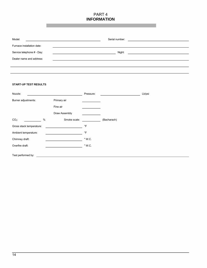
PART 4 INFORMATION
Model: Serial number:
Furnace installation date:
Service telephone # - Day:
Night:
Dealer name and address:
START-UP TEST RESULTS
Nozzle:
Pressure:
Lb/psi
Burner adjustments:
Primary air
Fine air
Draw Assembly
CO2:
% Smoke scale:
(Bacharach)
Gross stack temperature:
°F
Ambient temperature:
°F
Chimney draft:
" W.C.
Overfire draft:
" W.C.
Test performed by:
14
15
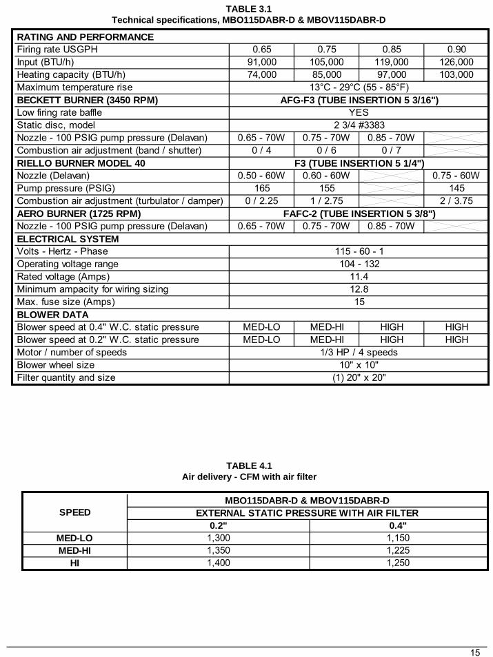
TABLE 3.1Technical specifications, MBO115DABR-D & MBOV115DABR-D
TABLE 4.1Air delivery - CFM with air filter
Firing rate USGPH 0.65 0.75 0.85 0.90Input (BTU/h) 91,000 105,000 119,000 126,000Heating capacity (BTU/h) 74,000 85,000 97,000 103,000Maximum temperature riseBECKETT BURNER (3450 RPM)Low firing rate baffleStatic disc, modelNozzle - 100 PSIG pump pressure (Delavan) 0.65 - 70W 0.75 - 70W 0.85 - 70WCombustion air adjustment (band / shutter) 0 / 4 0 / 6 0 / 7RIELLO BURNER MODEL 40Nozzle (Delavan) 0.50 - 60W 0.60 - 60W 0.75 - 60WPump pressure (PSIG) 165 155 145Combustion air adjustment (turbulator / damper) 0 / 2.25 1 / 2.75 2 / 3.75AERO BURNER (1725 RPM)Nozzle - 100 PSIG pump pressure (Delavan) 0.65 - 70W 0.75 - 70W 0.85 - 70W
Volts - Hertz - PhaseOperating voltage rangeRated voltage (Amps)Minimum ampacity for wiring sizingMax. fuse size (Amps)
Blower speed at 0.4" W.C. static pressure MED-LO MED-HI HIGH HIGHBlower speed at 0.2" W.C. static pressure MED-LO MED-HI HIGH HIGHMotor / number of speedsBlower wheel sizeFilter quantity and size
RATING AND PERFORMANCE
(1) 20" x 20"
13°C - 29°C (55 - 85°F)AFG-F3 (TUBE INSERTION 5 3/16")
YES2 3/4 #3383
F3 (TUBE INSERTION 5 1/4")
FAFC-2 (TUBE INSERTION 5 3/8")
1/3 HP / 4 speeds10" x 10"
BLOWER DATA
ELECTRICAL SYSTEM115 - 60 - 1104 - 132
11.412.815
0.2" 0.4"MED-LO 1,300 1,150MED-HI 1,350 1,225
HI 1,400 1,250
MBO115DABR-D & MBOV115DABR-DEXTERNAL STATIC PRESSURE WITH AIR FILTERSPEED
16
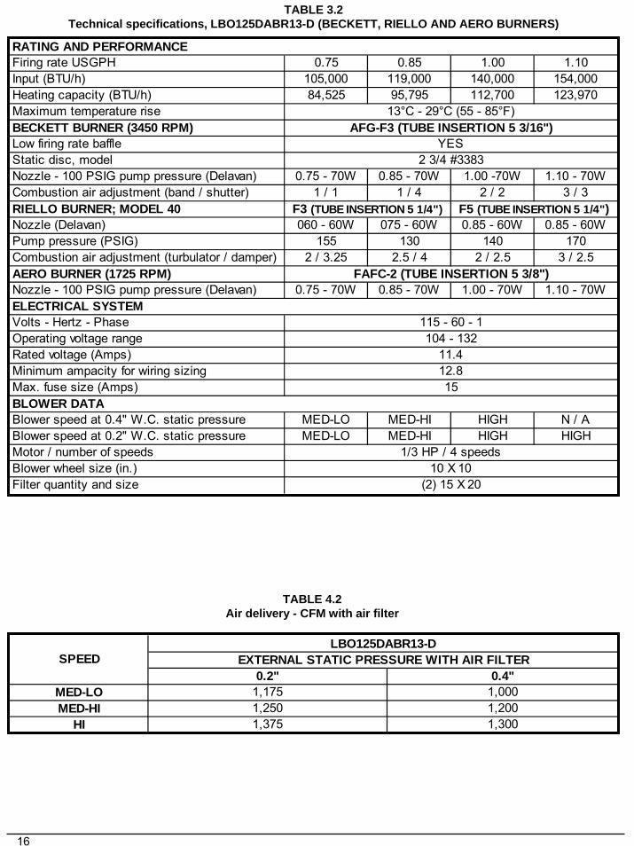
TABLE 3.2Technical specifications, LBO125DABR13-D (BECKETT, RIELLO AND AERO BURNERS)
TABLE 4.2Air delivery - CFM with air filter
0.2" 0.4"MED-LO 1,175 1,000MED-HI 1,250 1,200
HI 1,375 1,300
SPEEDLBO125DABR13-D
EXTERNAL STATIC PRESSURE WITH AIR FILTER
Firing rate USGPH 0.75 0.85 1.00 1.10Input (BTU/h) 105,000 119,000 140,000 154,000Heating capacity (BTU/h) 84,525 95,795 112,700 123,970Maximum temperature riseBECKETT BURNER (3450 RPM)Low firing rate baffleStatic disc, modelNozzle - 100 PSIG pump pressure (Delavan) 0.75 - 70W 0.85 - 70W 1.00 -70W 1.10 - 70WCombustion air adjustment (band / shutter) 1 / 1 1 / 4 2 / 2 3 / 3RIELLO BURNER; MODEL 40Nozzle (Delavan) 060 - 60W 075 - 60W 0.85 - 60W 0.85 - 60WPump pressure (PSIG) 155 130 140 170Combustion air adjustment (turbulator / damper) 2 / 3.25 2.5 / 4 2 / 2.5 3 / 2.5AERO BURNER (1725 RPM)Nozzle - 100 PSIG pump pressure (Delavan) 0.75 - 70W 0.85 - 70W 1.00 - 70W 1.10 - 70W
Volts - Hertz - PhaseOperating voltage rangeRated voltage (Amps)Minimum ampacity for wiring sizingMax. fuse size (Amps)
Blower speed at 0.4" W.C. static pressure MED-LO MED-HI HIGH N / ABlower speed at 0.2" W.C. static pressure MED-LO MED-HI HIGH HIGHMotor / number of speedsBlower wheel size (in.)Filter quantity and size
F5 (TUBE INSERTION 5 1/4")
2 3/4 #3383
F3 (TUBE INSERTION 5 1/4")
(2) 15 X 20
115 - 60 - 1104 - 132
11.412.815
1/3 HP / 4 speeds10 X 10
FAFC-2 (TUBE INSERTION 5 3/8")
13°C - 29°C (55 - 85°F)AFG-F3 (TUBE INSERTION 5 3/16")
YES
ELECTRICAL SYSTEM
BLOWER DATA
RATING AND PERFORMANCE
17
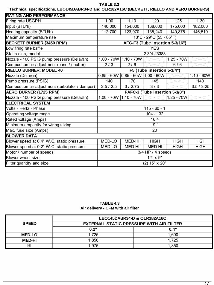
TABLE 3.3Technical specifications, LBO145DABR34-D and OLR182A16C (BECKETT, RIELLO AND AERO BURNERS)
TABLE 4.3Air delivery - CFM with air filter
0.2" 0.4"MED-LO 1,725 1,600MED-HI 1,850 1,725
HI 1,975 1,850
SPEEDLBO145DABR34-D & OLR182A16C
EXTERNAL STATIC PRESSURE WITH AIR FILTER
Firing rate USGPH 1.00 1.10 1.20 1.25 1.30Input (BTU/h) 140,000 154,000 168,000 175,000 182,000Heating capacity (BTU/h) 112,700 123,970 135,240 140,875 146,510Maximum temperature riseBECKETT BURNER (3450 RPM)Low firing rate baffleStatic disc, modelNozzle - 100 PSIG pump pressure (Delavan) 1.00 - 70W 1.10 - 70W 1.25 - 70WCombustion air adjustment (band / shutter) 2 / 3 2 / 6 6 / 6RIELLO BURNER; MODEL 40Nozzle (Delavan) 0.85 - 60W 0.85 - 60W 1.00 - 60W 1.10 - 60WPump pressure (PSIG) 140 170 145 140Combustion air adjustment (turbulator / damper) 2.5 / 2.5 3 / 2.75 3 / 3 3.5 / 3.25AERO BURNER (1725 RPM)Nozzle - 100 PSIG pump pressure (Delavan) 1.00 - 70W 1.10 - 70W 1.25 - 70W
Volts - Hertz - PhaseOperating voltage rangeRated voltage (Amps)Minimum ampacity for wiring sizingMax. fuse size (Amps)
Blower speed at 0.4" W.C. static pressure MED-LO MED-HI HIGH HIGH HIGHBlower speed at 0.2" W.C. static pressure MED-LO MED-HI MED-HI HIGH HIGHMotor / number of speedsBlower wheel sizeFilter quantity and size
AFG-F3 (Tube insertion 5-3/16")
RATING AND PERFORMANCE
13°C - 29°C (55 - 85°F)
104 - 13216.419.120
(2) 15" x 20"
YES2 3/4 #3383
F5 (Tube insertion 5-1/4")
FAFC-3 (Tube insertion 5-3/8")
ELECTRICAL SYSTEM
BLOWER DATA
3/4 HP / 4 speeds12" x 9"
115 - 60 - 1
18
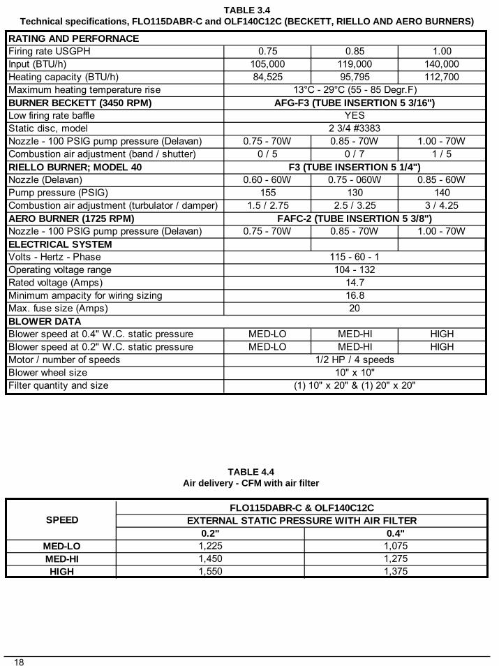
TABLE 3.4Technical specifications, FLO115DABR-C and OLF140C12C (BECKETT, RIELLO AND AERO BURNERS)
TABLE 4.4Air delivery - CFM with air filter
Firing rate USGPH 0.75 0.85 1.00Input (BTU/h) 105,000 119,000 140,000Heating capacity (BTU/h) 84,525 95,795 112,700Maximum heating temperature riseBURNER BECKETT (3450 RPM)Low firing rate baffleStatic disc, modelNozzle - 100 PSIG pump pressure (Delavan) 0.75 - 70W 0.85 - 70W 1.00 - 70WCombustion air adjustment (band / shutter) 0 / 5 0 / 7 1 / 5RIELLO BURNER; MODEL 40Nozzle (Delavan) 0.60 - 60W 0.75 - 060W 0.85 - 60WPump pressure (PSIG) 155 130 140Combustion air adjustment (turbulator / damper) 1.5 / 2.75 2.5 / 3.25 3 / 4.25AERO BURNER (1725 RPM)Nozzle - 100 PSIG pump pressure (Delavan) 0.75 - 70W 0.85 - 70W 1.00 - 70WELECTRICAL SYSTEMVolts - Hertz - PhaseOperating voltage rangeRated voltage (Amps)Minimum ampacity for wiring sizingMax. fuse size (Amps)
Blower speed at 0.4" W.C. static pressure MED-LO MED-HI HIGHBlower speed at 0.2" W.C. static pressure MED-LO MED-HI HIGHMotor / number of speedsBlower wheel sizeFilter quantity and size
RATING AND PERFORNACE
(1) 10" x 20" & (1) 20" x 20"
104 - 13214.716.820
BLOWER DATA
1/2 HP / 4 speeds10" x 10"
115 - 60 - 1
13°C - 29°C (55 - 85 Degr.F)AFG-F3 (TUBE INSERTION 5 3/16")
YES2 3/4 #3383
F3 (TUBE INSERTION 5 1/4")
FAFC-2 (TUBE INSERTION 5 3/8")
0.2" 0.4"MED-LO 1,225 1,075MED-HI 1,450 1,275HIGH 1,550 1,375
SPEEDFLO115DABR-C & OLF140C12C
EXTERNAL STATIC PRESSURE WITH AIR FILTER
19
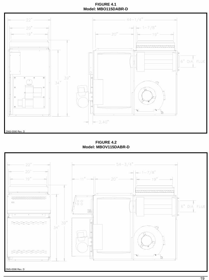
DNS-0596 Rev. D
FIGURE 4.2Model: MBOV115DABR-D
FIGURE 4.1Model: MBO115DABR-D
DNS-0590 Rev. D
20
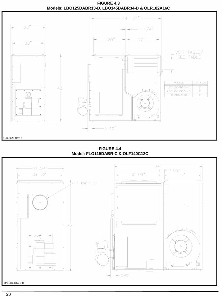
FIGURE 4.3Models: LBO125DABR13-D, LBO145DABR34-D & OLR182A16C
FIGURE 4.4Model: FLO115DABR-C & OLF140C12C
DNS-0666 Rev. C
DNS-0576 Rev. F
21
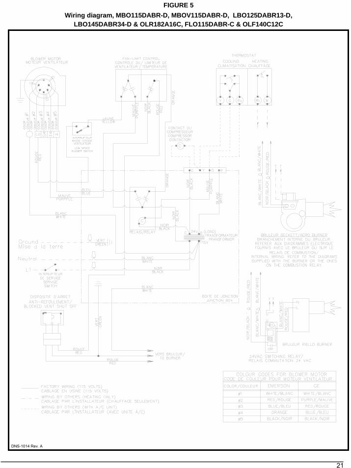
FIGURE 5Wiring diagram, MBO115DABR-D, MBOV115DABR-D, LBO125DABR13-D,
LBO145DABR34-D & OLR182A16C, FLO115DABR-C & OLF140C12C
DNS-1014 Rev. A
22
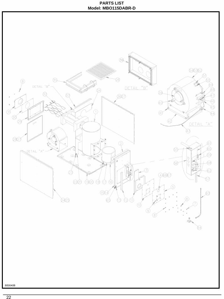
PARTS LISTModel: MBO115DABR-D
B50040B
23
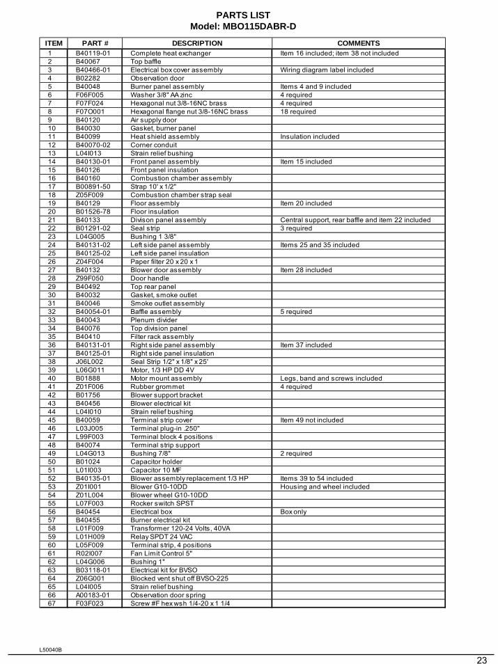
PARTS LISTModel: MBO115DABR-D
ITEM PART # DESCRIPTION COMMENTS1 B40119-01 Complete heat exchanger Item 16 included; item 38 not included2 B40067 Top baffle3 B40466-01 Electrical box cover assembly Wiring diagram label included4 B02282 Observation door5 B40048 Burner panel assembly Items 4 and 9 included6 F06F005 Washer 3/8" AA zinc 4 required7 F07F024 Hexagonal nut 3/8-16NC brass 4 required8 F07O001 Hexagonal flange nut 3/8-16NC brass 18 required9 B40120 Air supply door10 B40030 Gasket, burner panel11 B40099 Heat shield assembly Insulation included12 B40070-02 Corner conduit13 L04I013 Strain relief bushing14 B40130-01 Front panel assembly Item 15 included15 B40126 Front panel insulation16 B40160 Combustion chamber assembly17 B00891-50 Strap 10' x 1/2" 18 Z05F009 Combustion chamber strap seal19 B40129 Floor assembly Item 20 included20 B01526-78 Floor insulation21 B40133 Divison panel assembly Central support, rear baffle and item 22 included22 B01291-02 Seal strip 3 required23 L04G005 Bushing 1 3/8''24 B40131-02 Left side panel assembly Items 25 and 35 included25 B40125-02 Left side panel insulation26 Z04F004 Paper filter 20 x 20 x 1 27 B40132 Blower door assembly Item 28 included28 Z99F050 Door handle29 B40492 Top rear panel30 B40032 Gasket, smoke outlet31 B40046 Smoke outlet assembly32 B40054-01 Baffle assembly 5 required33 B40043 Plenum divider34 B40076 Top division panel35 B40410 Filter rack assembly36 B40131-01 Right side panel assembly Item 37 included37 B40125-01 Right side panel insulation38 J06L002 Seal Strip 1/2" x 1/8" x 25'39 L06G011 Motor, 1/3 HP DD 4V40 B01888 Motor mount assembly Legs, band and screws included41 Z01F006 Rubber grommet 4 required42 B01756 Blower support bracket43 B40456 Blower electrical kit44 L04I010 Strain relief bushing45 B40059 Terminal strip cover Item 49 not included46 L03J005 Terminal plug-in .250''47 L99F003 Terminal block 4 positions48 B40074 Terminal strip support49 L04G013 Bushing 7/8" 2 required50 B01024 Capacitor holder51 L01I003 Capacitor 10 MF 52 B40135-01 Blower assembly replacement 1/3 HP Items 39 to 54 included53 Z01I001 Blower G10-10DD Housing and wheel included54 Z01L004 Blower wheel G10-10DD55 L07F003 Rocker switch SPST56 B40454 Electrical box Box only57 B40455 Burner electrical kit58 L01F009 Transformer 120-24 Volts, 40VA59 L01H009 Relay SPDT 24 VAC60 L05F009 Terminal strip, 4 positions61 R02I007 Fan Limit Control 5"62 L04G006 Bushing 1''63 B03118-01 Electrical kit for BVSO64 Z06G001 Blocked vent shut off BVSO-22565 L04I005 Strain relief bushing66 A00183-01 Observation door spring67 F03F023 Screw #F hex wsh 1/4-20 x 1 1/4
L50040B
24
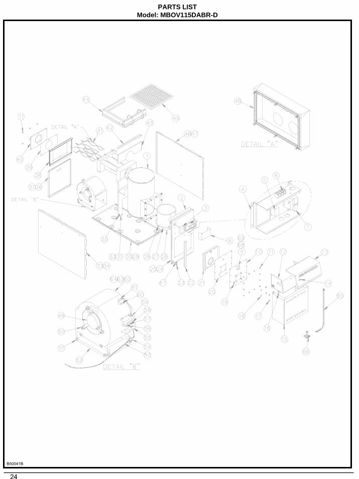
PARTS LISTModel: MBOV115DABR-D
B50041B
25
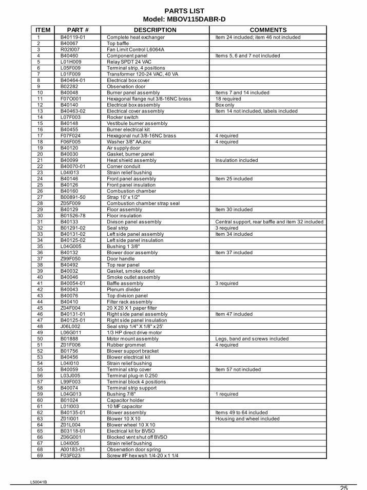
PARTS LISTModel: MBOV115DABR-D
ITEM PART # DESCRIPTION COMMENTS1 B40119-01 Complete heat exchanger Item 24 included; item 46 not included2 B40067 Top baffle3 R02I007 Fan Limit Control L6064A4 B40460 Component panel Items 5, 6 and 7 not included5 L01H009 Relay SPDT 24 VAC6 L05F009 Terminal strip, 4 positions7 L01F009 Transformer 120-24 VAC, 40 VA8 B40464-01 Electrical box cover9 B02282 Observation door10 B40048 Burner panel assembly Items 7 and 14 included11 F07O001 Hexagonal flange nut 3/8-16NC brass 18 required12 B40140 Electrical box assembly Box only13 B40463-02 Electrical cover assembly Item 14 not included, labels included14 L07F003 Rocker switch15 B40148 Vestibule burner assembly16 B40455 Burner electrical kit17 F07F024 Hexagonal nut 3/8-16NC brass 4 required18 F06F005 Washer 3/8" AA zinc 4 required19 B40120 Air supply door20 B40030 Gasket, burner panel21 B40099 Heat shield assembly Insulation included22 B40070-01 Corner conduit23 L04I013 Strain relief bushing24 B40146 Front panel assembly Item 25 included25 B40126 Front panel insulation26 B40160 Combustion chamber27 B00891-50 Strap 10' x 1/2"28 Z05F009 Combustion chamber strap seal29 B40129 Floor assembly Item 30 included30 B01526-78 Floor insulation31 B40133 Divison panel assembly Central support, rear baffle and item 32 included32 B01291-02 Seal strip 3 required33 B40131-02 Left side panel assembly Item 34 included34 B40125-02 Left side panel insulation35 L04G005 Bushing 1 3/8''36 B40132 Blower door assembly Item 37 included37 Z99F050 Door handle38 B40492 Top rear panel39 B40032 Gasket, smoke outlet40 B40046 Smoke outlet assembly41 B40054-01 Baffle assembly 3 required42 B40043 Plenum divider43 B40076 Top division panel44 B40410 Filter rack assembly45 Z04F004 20 X 20 X 1 paper filter46 B40131-01 Right side panel assembly Item 47 included47 B40125-01 Right side panel insulation48 J06L002 Seal strip 1/4" X 1/8" x 25'49 L06G011 1/3 HP direct drive motor50 B01888 Motor mount assembly Legs, band and screws included51 Z01F006 Rubber grommet 4 required52 B01756 Blower support bracket53 B40456 Blower electrical kit54 L04I010 Strain relief bushing55 B40059 Terminal strip cover Item 57 not included56 L03J005 Terminal plug-in 0.25057 L99F003 Terminal block 4 positions58 B40074 Terminal strip support59 L04G013 Bushing 7/8" 1 required60 B01024 Capacitor holder61 L01I003 10 MF capacitor62 B40135-01 Blower assembly Items 49 to 64 included63 Z01I001 Blower 10 X 10 Housing and wheel included64 Z01L004 Blower wheel 10 X 1065 B03118-01 Electrical kit for BVSO66 Z06G001 Blocked vent shut off BVSO67 L04I005 Strain relief bushing68 A00183-01 Observation door spring69 F03F023 Screw #F hex wsh 1/4-20 x 1 1/4
L50041B
26
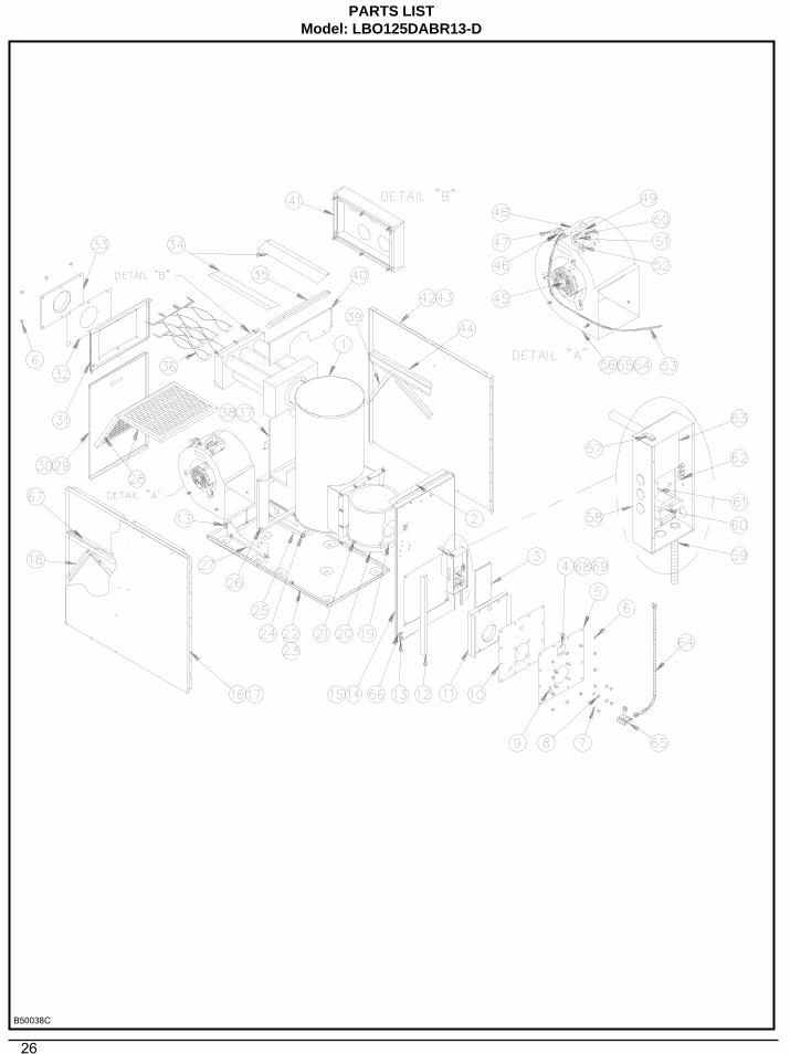
PARTS LISTModel: LBO125DABR13-D
B50038C
27
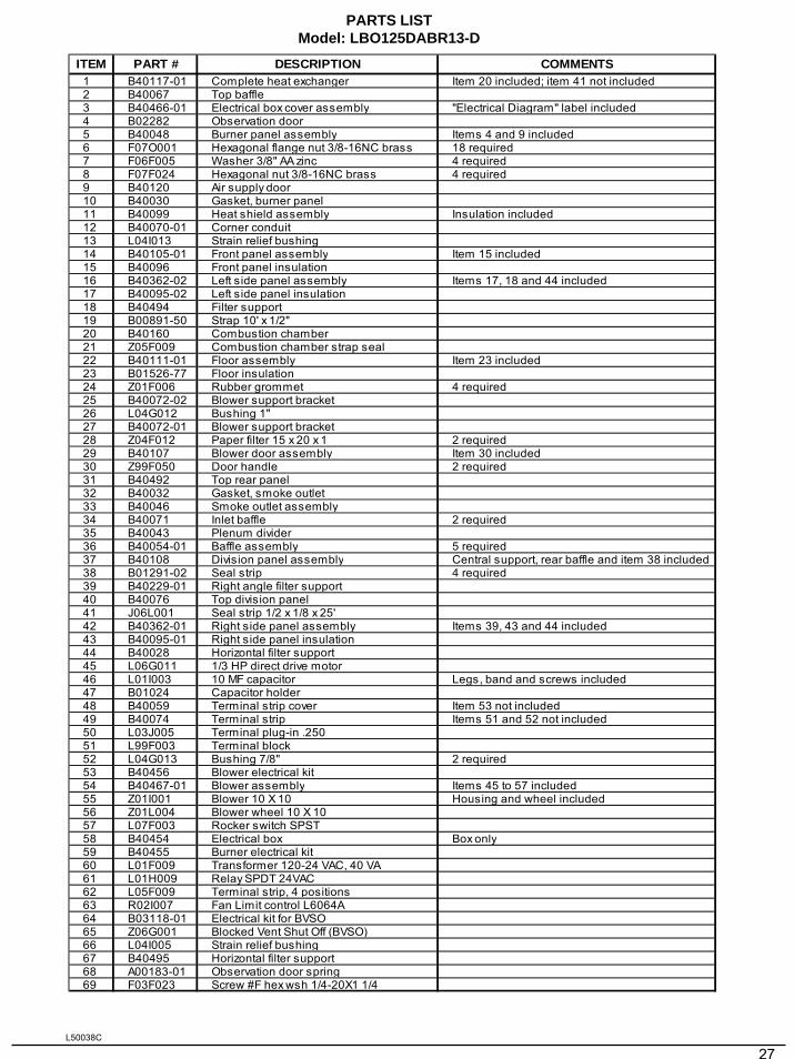
PARTS LISTModel: LBO125DABR13-D
ITEM PART # DESCRIPTION COMMENTS1 B40117-01 Complete heat exchanger Item 20 included; item 41 not included2 B40067 Top baffle3 B40466-01 Electrical box cover assembly "Electrical Diagram" label included4 B02282 Observation door5 B40048 Burner panel assembly Items 4 and 9 included6 F07O001 Hexagonal flange nut 3/8-16NC brass 18 required7 F06F005 Washer 3/8" AA zinc 4 required8 F07F024 Hexagonal nut 3/8-16NC brass 4 required9 B40120 Air supply door10 B40030 Gasket, burner panel11 B40099 Heat shield assembly Insulation included12 B40070-01 Corner conduit13 L04I013 Strain relief bushing14 B40105-01 Front panel assembly Item 15 included15 B40096 Front panel insulation16 B40362-02 Left side panel assembly Items 17, 18 and 44 included17 B40095-02 Left side panel insulation18 B40494 Filter support19 B00891-50 Strap 10' x 1/2"20 B40160 Combustion chamber21 Z05F009 Combustion chamber strap seal22 B40111-01 Floor assembly Item 23 included23 B01526-77 Floor insulation24 Z01F006 Rubber grommet 4 required25 B40072-02 Blower support bracket26 L04G012 Bushing 1"27 B40072-01 Blower support bracket28 Z04F012 Paper filter 15 x 20 x 1 2 required29 B40107 Blower door assembly Item 30 included30 Z99F050 Door handle 2 required31 B40492 Top rear panel32 B40032 Gasket, smoke outlet 33 B40046 Smoke outlet assembly34 B40071 Inlet baffle 2 required35 B40043 Plenum divider36 B40054-01 Baffle assembly 5 required37 B40108 Division panel assembly Central support, rear baffle and item 38 included38 B01291-02 Seal strip 4 required39 B40229-01 Right angle filter support40 B40076 Top division panel41 J06L001 Seal strip 1/2 x 1/8 x 25'42 B40362-01 Right side panel assembly Items 39, 43 and 44 included43 B40095-01 Right side panel insulation44 B40028 Horizontal filter support45 L06G011 1/3 HP direct drive motor46 L01I003 10 MF capacitor Legs, band and screws included47 B01024 Capacitor holder48 B40059 Terminal strip cover Item 53 not included49 B40074 Terminal strip Items 51 and 52 not included50 L03J005 Terminal plug-in .25051 L99F003 Terminal block52 L04G013 Bushing 7/8" 2 required53 B40456 Blower electrical kit54 B40467-01 Blower assembly Items 45 to 57 included55 Z01I001 Blower 10 X 10 Housing and wheel included56 Z01L004 Blower wheel 10 X 1057 L07F003 Rocker switch SPST58 B40454 Electrical box Box only59 B40455 Burner electrical kit60 L01F009 Transformer 120-24 VAC, 40 VA61 L01H009 Relay SPDT 24VAC62 L05F009 Terminal strip, 4 positions 63 R02I007 Fan Limit control L6064A64 B03118-01 Electrical kit for BVSO65 Z06G001 Blocked Vent Shut Off (BVSO)66 L04I005 Strain relief bushing67 B40495 Horizontal filter support68 A00183-01 Observation door spring69 F03F023 Screw #F hex wsh 1/4-20X1 1/4
L50038C
28
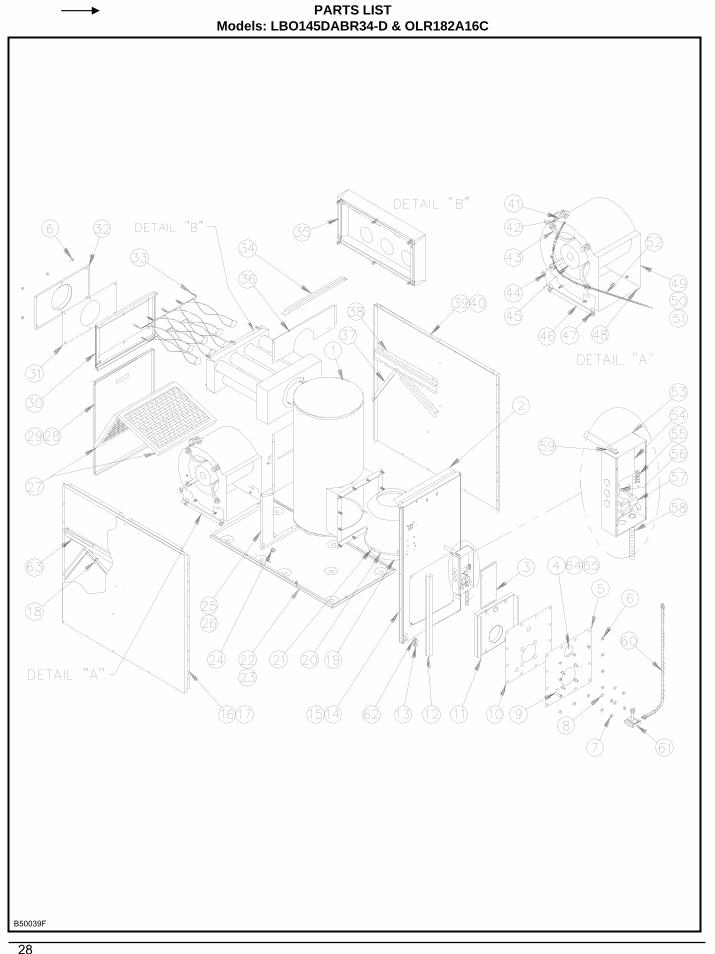
PARTS LISTModels: LBO145DABR34-D & OLR182A16C
B50039F
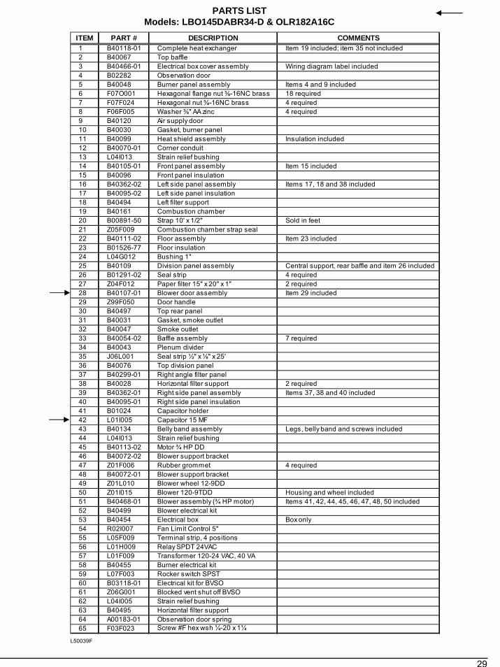
29
PARTS LISTModels: LBO145DABR34-D & OLR182A16C
ITEM PART # DESCRIPTION COMMENTS1 B40118-01 Complete heat exchanger Item 19 included; item 35 not included2 B40067 Top baffle3 B40466-01 Electrical box cover assembly Wiring diagram label included4 B02282 Observation door5 B40048 Burner panel assembly Items 4 and 9 included6 F07O001 Hexagonal flange nut ⅜-16NC brass 18 required7 F07F024 Hexagonal nut ⅜-16NC brass 4 required8 F06F005 Washer ⅜" AA zinc 4 required9 B40120 Air supply door10 B40030 Gasket, burner panel11 B40099 Heat shield assembly Insulation included12 B40070-01 Corner conduit13 L04I013 Strain relief bushing14 B40105-01 Front panel assembly Item 15 included15 B40096 Front panel insulation16 B40362-02 Left side panel assembly Items 17, 18 and 38 included17 B40095-02 Left side panel insulation18 B40494 Left filter support19 B40161 Combustion chamber20 B00891-50 Strap 10' x 1/2" Sold in feet21 Z05F009 Combustion chamber strap seal22 B40111-02 Floor assembly Item 23 included23 B01526-77 Floor insulation24 L04G012 Bushing 1"25 B40109 Division panel assembly Central support, rear baffle and item 26 included26 B01291-02 Seal strip 4 required27 Z04F012 Paper filter 15" x 20" x 1" 2 required28 B40107-01 Blower door assembly Item 29 included29 Z99F050 Door handle30 B40497 Top rear panel31 B40031 Gasket, smoke outlet32 B40047 Smoke outlet33 B40054-02 Baffle assembly 7 required34 B40043 Plenum divider35 J06L001 Seal strip ½" x ⅛" x 25' 36 B40076 Top division panel37 B40299-01 Right angle filter panel38 B40028 Horizontal filter support 2 required39 B40362-01 Right side panel assembly Items 37, 38 and 40 included40 B40095-01 Right side panel insulation41 B01024 Capacitor holder42 L01I005 Capacitor 15 MF 43 B40134 Belly band assembly Legs, belly band and screws included44 L04I013 Strain relief bushing45 B40113-02 Motor ¾ HP DD 46 B40072-02 Blower support bracket47 Z01F006 Rubber grommet 4 required48 B40072-01 Blower support bracket49 Z01L010 Blower wheel 12-9DD50 Z01I015 Blower 120-9TDD Housing and wheel included51 B40468-01 Blower assembly (¾ HP motor) Items 41, 42, 44, 45, 46, 47, 48, 50 included52 B40499 Blower electrical kit53 B40454 Electrical box Box only54 R02I007 Fan Limit Control 5"55 L05F009 Terminal strip, 4 positions56 L01H009 Relay SPDT 24VAC57 L01F009 Transformer 120-24 VAC, 40 VA58 B40455 Burner electrical kit59 L07F003 Rocker switch SPST60 B03118-01 Electrical kit for BVSO61 Z06G001 Blocked vent shut off BVSO62 L04I005 Strain relief bushing63 B40495 Horizontal filter support64 A00183-01 Observation door spring65 F03F023 Screw #F hex wsh ¼-20 x 1¼
L50039F
30
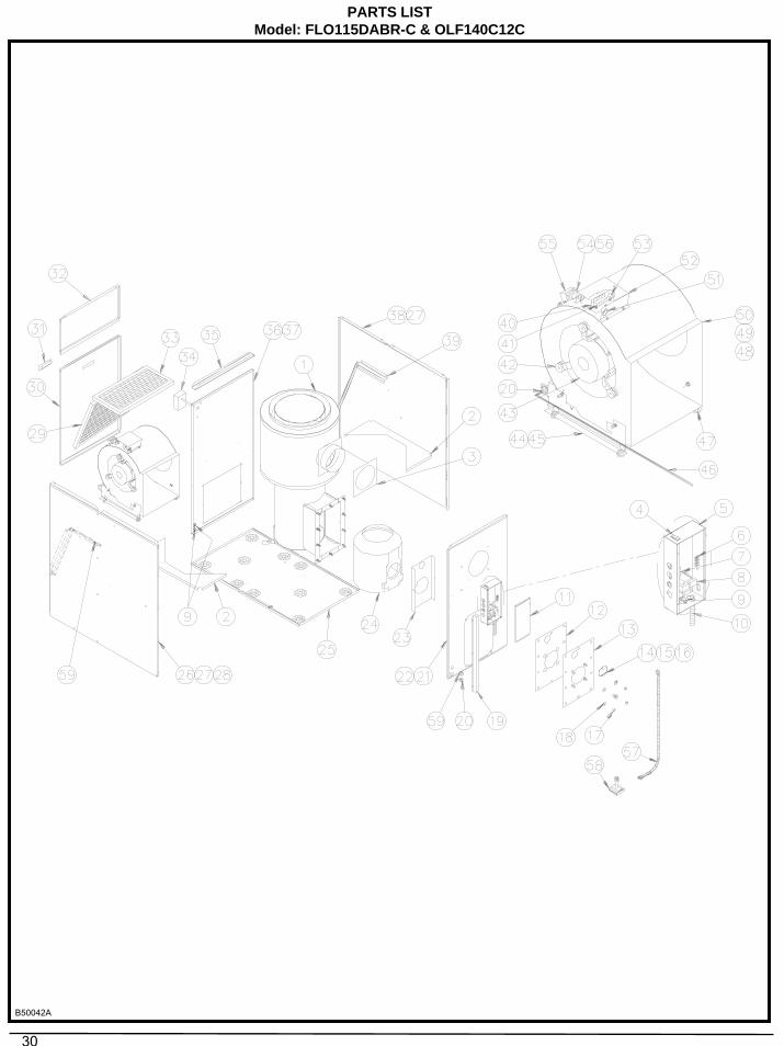
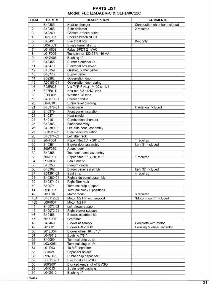
PARTS LISTModel: FLO115DABR-C & OLF140C12C
B50042A
31
PARTS LISTModel: FLO115DABR-C & OLF140C12C
ITEM PART # DESCRIPTION COMMENTS1 B40385 Heat exchanger Combustion chamber included2 B40358 Side deflector 2 required3 B40360 Gasket, smoke outlet4 L07F003 Rocker switch SPST5 B40491 Electrical box Box only6 L05F009 Single terminal strip7 L01H009 Relay SPDT 24 VAC8 L01F009 Transformer 120-24 V, 40 VA9 L04G006 Bushing 1''10 B40455 Burner electrical kit11 B40470 Electrical box cover12 B40359 Gasket, burner panel13 B40376 Burner panel14 B02282 Observation door15 A00183-01 Observation door spring16 F03F023 Vis TYP F Hex 1/4-20 x 11/417 F07F011 Hex nut 3/8-16NC zinc18 F06F005 Washer 3/8 zinc19 B40070-01 Corner conduit20 L04I010 Strain relief bushing21 B40378-01 Front panel Insulation included22 B40379 Front panel insulation23 B40371 Heat shield24 B40161 Combustion chamber25 B40383 Floor assembly26 B40380-02 Left side panel assembly27 B01526-82 Side panel insulation28 B40374-02 Left filter rack29 Z04F004 Paper filter 20" x 20" x 1" 1 required30 B40381 Blower door assembly Item 31 included31 Z99F050 Acces door32 B40356 Top back panel assembly33 Z04F001 Paper filter 10" x 20" x 1" 1 required34 R02I007 Fan Limit 5"35 B40353 Plenum divider36 B40382 Divider panel assembly Item 37 included37 B01291-02 Seal strip 4 required38 B40380-01 Right side panel assembly39 B40374-01 Right filter rack40 B40074 Terminal strip support41 L99F003 Terminal block 6 positions42 Z01I016 Motor mount 3 required43A B40112-02 Motor 1/2 HP with support "Motor mount" included43B L06H007 Motor 1/2 HP44 B40072-02 Left blower support45 B40072-01 Right blower support46 B40456 Blower, electrical kit47 Z01F006 Grommet48 B40469 Blower assembly Complete with motor49 Z01I001 Blower G10-10DD Housing & wheel included50 Z01L004 Blower wheel 10" x 10"51 L04G013 Bushing 7/8 ''52 B40059 Terminal strip cover53 L03J005 Terminal plug-in 1/454 L01I003 10 MF capacitor55 B01024 Capacitor holder56 L99Z007 Rubber cap capacitor57 B03118-01 Electrical kit BVSO58 Z06G001 Blocked vent shut off BVSO59 L04I013 Strain relief bushing60 L04G012 Bushing 1''
L50042A