offshore technology report 2001/0492.1 inclining tests consideration should be given to carrying out...
TRANSCRIPT

HSEHealth & Safety
Executive
Stability
OFFSHORE TECHNOLOGY REPORT
2001/049

HSEHealth & Safety
Executive
Stability
Edited under the HSE Technical Support Agreement by BOMEL LtdLedger House
Forest Green RoadFifield
MaidenheadBerkshire SL6 2NR
HSE BOOKS

ii
© Crown copyright 2002Applications for reproduction should be made in writing to:Copyright Unit, Her Majesty’s Stationery Office,St Clements House, 2-16 Colegate, Norwich NR3 1BQ
First published 2002
ISBN 0 7176 2508 7
All rights reserved. No part of this publication may bereproduced, stored in a retrieval system, or transmittedin any form or by any means (electronic, mechanical,photocopying, recording or otherwise) without the priorwritten permission of the copyright owner.
This report is made available by the Health and SafetyExecutive as part of a series of reports of work which hasbeen supported by funds provided by the Executive.Neither the Executive, nor the contractors concernedassume any liability for the reports nor do theynecessarily reflect the views or policy of the Executive.
iii
CONTENTS Page No FOREWORD v 1 INTRODUCTION AND SCOPE 1 2 STABILITY 3 2.1 Inclining Tests 3 2.2 Righting Moment and Heeling Moment Curves 4 2.3 Intact Stability Criteria 6 2.4 Assumptions for Damage and Flooding 8 2.5 Permeabilities 12 2.6 Damaged Stability Criteria 12 2.7 KG Limit Curves 14 3 WATERTIGHT INTEGRITY 17 3.1 General Recommendations for Watertight Integrity 17 3.2 Internal Pipes, Ducts and Associated Valves 18 3.3 Inlets, Discharges and Associated Valves 18 3.4 Internal Access Opening 19 3.5 External Openings 19 3.6 Flooding Alarms 20 4 BALLASTING 23 4.1 Bilge Pumping Systems 23 5 BALLAST SYSTEMS FOR COLUMN STABILIZED UNITS 25 5.1 Ballast Control Room 25 5.2 Ballast System Redundancy 26 5.3 Ballast System Safety Features 27 5.4 Ballast System Components and Equipment 28 5.5 System Capability Following Damage or Flooding 29 6 REFERENCES 31

iv

v
FOREWORD
This document provides technical information previously contained in the Fourth Edition of the Health and Safety Executive’s ‘Offshore Installations: Guidance on Design, Construction and Certification’ (1990 edition plus amendments)(1). The ‘Guidance’ was originally published in support of the certification regime under SI289, the Offshore Installations (Construction and Survey) Regulations 1974(2). However, SI289 was revoked by the Offshore Installations (Design and Construction, etc) Regulations, 1996, which also introduced the verification provisions into the Offshore Installations (Safety Case) Regulations, 1992. The ‘Guidance’ was formally withdrawn in its entirety on 30 June 1998 (see HSE OSD Operations Notice 27(3)).
The withdrawal of the ‘Guidance’ was not a reflection of the soundness (or otherwise) of the technical information it contained; some sections (or part of sections) of the ‘Guidance’ are currently referred to by the offshore industry. For this reason, after consultation with industry, relevant sections are now published as separate documents in the HSE Offshore Technology (OT) Report series.
It should be noted that the technical content of the ‘Guidance’ has not been updated as part of the re-formatting for OTO publication, although prescriptive requirements and reference to the former regulatory regime have been removed. The user of this document must therefore assess the appropriateness and currency of the technical information for any specific application. Additionally, the user should be aware that published sections may cease to be applicable in time and should check with Operations Notice 27, which can be viewed at http://www.hse.gov.uk/hid/osd/notices/on_index.htm, for their current status.

vi

1
1. INTRODUCTION AND SCOPE This Offshore Technology (OT) Report provides information on the stability of floating Installations. Both intact and damaged stability are covered, as well as aspects which affect buoyancy and stability, such as watertight compartments and ballasting and bilge pumping systems. While the information is intended for mobile Installations, including mobile offshore units (MOUs), it may be applied where appropriate to fixed floating Installations providing any special features of the permanent moorings or tethers are taken into account. The information is based on guidance previously contained in Section 31 of the Fourth Edition of the Health and Safety Executive’s ‘Offshore Installations: Guidance on Design, Construction and Certification’(1) which was withdrawn in 1998. As discussed in the Foreword, whilst the text has been re-formatted for Offshore Technology publication, the technical content has not been updated. The appropriateness and currency of the information contained in this document must therefore be assessed by the user for any specific application.

2
3
2. STABILITY This information is intended to provide an adequate level of stability during routine operations of floating Installations. The aim is to take account of the most probable damage cases, in particular low energy collisions with supply vessels during loading, towing and anchor handling. Some types of unit (e.g. tethered buoyant Installations and single point moorings) are likely to require specific consideration, but the adequacy of stability should be determined both in intact conditions and following damage or flooding as described in Section 2.4. In this document the word ‘heel’ means, in general, inclination of the unit from the upright in any direction. The information on metacentric heights presented in this document is supported by a background report OTH 84 211(4). 2.1 INCLINING TESTS Consideration should be given to carrying out an inclining test on the first unit of a design, when as near to completion as possible, to determine accurately the lightship weight and position of centre of gravity. The test will need to be conducted in accordance with an approved procedure. For successive units of a design which are identical with regard to hull form and arrangement (with the exception of minor changes in machinery or outfit) detailed weight calculations showing only the differences of weight and centres of gravity may be acceptable. However, the calculated changes in weight and position of centre of gravity should be small, and the accuracy of the calculations confirmed by a deadweight survey. An inclining test would need to be carried out on every column-stabilised unit, regardless of similarity with other units of the same design. It is suggested that a deadweight survey should be carried out on each surface and self-elevating unit during each subsequent major survey. If there is a significant discrepancy between this result and that expected from weight records, then an inclining test may be required for surface units. For self-elevating units, the lightship weight and centre of gravity and variable load will need to be re-assessed considering the results of the deadweight survey. It is suggested that an inclining test should be carried out during each major survey for every column-stabilised unit. After the second inclining test, the period between subsequent inclining tests may be extended to every other major survey if there has been satisfactory agreement between weight records and the results of the second test. In which case, there will need to be a deadweight survey in accordance with the preceding paragraph. Inclining tests may not be necessary in service where an onboard stability device is used at regular intervals, e.g. on a monthly basis. A comprehensive and up-to-date record should be kept in the form of an on-board log of all changes to the unit that affect its lightship weight and/or its centre of gravity. A procedure should be agreed for the notification of such changes (i.e. whether individual major changes or an accumulation of minor

4
changes). The extent of these changes may necessitate a deadweight survey or an inclining test being undertaken before they would normally be due. 2.2 RIGHTING MOMENT AND HEELING MOMENT CURVES Consideration should be given to preparing curves of righting and wind heeling moments similar to Figure 1, with supporting calculations, covering the full range of draughts including those in transit conditions. The wind heeling moment calculations should take into account the maximum variable deck load and equipment in the most unfavourable position possible. The righting moment and wind heeling moment curves should be related to the most critical axes (see Sections 2.3 and 2.6). The unit should be assumed floating free of mooring restraint, except as noted below. In the case of self-elevating units, due allowance should be made for the buoyancy of submerged leg structure including spud cans or mat. Appendages on other types of unit should be similarly considered. Where equipment is of such a nature that it can be lowered and stowed (e.g. drilling masts, legs of self-elevating units), additional wind heeling moment curves may be required, and such data should clearly indicate the position of such equipment (see Section 2.6). The curves of wind heeling moments can be drawn for wind forces calculated using the following formula:
F = 0.5 CS CH ? V2 A (Newtons) where: F = the wind force (Newtons) CS = the shape coefficient depending on the shape of the structural member exposed to
the wind (see Table 1) CH = the height coefficient depending on the height above sea level of the structural
member exposed to wind (see Table 2) ? = the air mass density (1.222 kilograms per cubic metre) V = the wind velocity (metres per second) A = the projected area of all exposed surfaces in either the upright or the heeled
condition (square metres).
Table 1 Values of the shape coefficient Cs
Shape Cs
Spherical Cylindrical Large flat surface (hull, deckhouse, smooth under deck areas) Drilling derrick Wires Exposed beams and girders under deck Small parts Isolated shapes (crane, beam, etc.) Clustered deck houses or similar structures
0.4 0.5 1.0
1.25 1.2 1.3 1.4 1.5 1.1

5
Table 2 Values of the height coefficient CH
Height above sea level (m) CH
0 - 15.3 15.3 - 30.5 30.5 - 46.0 46.0 - 61.0 61.0 - 76.0 76.0 - 91.5
91.5 - 106.5 106.5 - 122.0 102.0 - 137.0 137.0 - 152.5 152.5 - 167.5 167.5 - 183.0 183.0 - 198.0 198.0 - 213.5 213.5 - 228.5 228.5 - 244.0 244.0 - 256.0
above 256
1.00 1.10 1.20 1.30 1.37 1.43 1.48 1.52 1.56 1.60 1.63 1.67 1.70 1.72 1.75 1.77 1.79 1.80
Wind forces should be considered from any direction for column-stabilised units. It is suggested that the wind velocity should be a minimum of 36 metres per second (70 knots) for normal operating, transit and intermediate conditions, a minimum of 51.5 metres per second (100 knots) for severe storm conditions, and a minimum of 25.8 metres per second (50 knots) for damaged conditions. (Refer to Section 2.7 for a more comprehensive definition of conditions). In calculating the projected areas in the vertical plane, the area of surfaces exposed to wind due to heel or trim (such as under decks etc.) should be included using the appropriate shape factor. Open truss work may be approximated as 30% of the projected block area of both the front and back sections, i.e. 60% of the projected block area of one side. In calculating the wind heeling moments, the lever of the wind overturning force should be taken vertically from the centre of pressure of all exposed surfaces to the centre of lateral resistance of the underwater body of the unit. In the case of units having a dynamic positioning system, wind heeling moment curves should also be evaluated from the difference in force between the maximum applied thrust and the total wind force acting at the centre of lateral resistance. Here, it is assumed that the maximum applied thrust acts at the thruster elevation. It is still necessary to comply with the stability criteria in both cases. The wind heeling moments should be calculated for a sufficient number of heel angles to define the curve. For ship-shaped hulls the curve may generally be assumed to vary as the cosine function of vessel heel; it should be noted, however, that structures such as helidecks may produce a signif icant effect on total heeling moment as the vessel is heeled, and such effects should be taken into account. Wind heeling moments derived from wind tunnel tests on a representative model of the unit may be used as a supplement to those derived by the procedure suggested above.

6
2.3 INTACT STABILITY CRITERIA It is suggested that the ratio of the area under the righting moment curve to that under the heeling moment curve should not be less than 1.3 for column stabilized units and not less than 1.4 for surface and self-elevating units. These areas should be measured from the upright position to an angle of heel, not exceeding either the angle of first downflooding (refer to Section 3) or the second intercept of the wind heeling and righting moment curves, whichever is the lesser (see Figure 1). For surface and self-elevating units, it is suggested that the range of positive stability to the second intercept for severe storm winds (i.e. at least 51.5 metres per second) should be at least 30°. For self-elevating units, the range of stability beyond 20° may be considered notional from the point of view of the position of downflooding points, the strength of structure and closing appliances. The range of stability for self-elevating units, neglecting wind heeling, may be reduced to 20° for field moves taking place within the period of an accurate and favourable weather forecast. This allows the unit to be raised from the water, or lowered into the water and to seek shelter. Any associated limitations should be noted. For self-elevating units, alternative stability range criteria, which provide adequate margins of stability in certain environmental conditions (e.g. for extended field moves in areas or seasons where storms would be less than the all-year severe storm condition) may be appropriate. Consideration should be given to limiting the static angle of heel due to wind to 15° in any condition. It is suggested that the metacentric height (GM) should be at least 0.5 metres for self-elevating units and at least 0.3 metres for surface units. Column stabilized units should have a GM of at least 1.0 metres in the operating, transit and severe storm conditions, but GM may be reduced to 0.3 metres in intermediate or temporary conditions (i.e. during changes of draught between transit, operating or severe storm conditions). The righting lever curve up to the angle of downflooding or the angle of maximum righting lever or 15°, whichever is the least, will need to be such that:
GZ ú 0.5 GM0 sin θ where GM0 = minimum permissible value of GM (as presented in previous paragraph).

7
Figure 1 Intact Stability Criteria
At each draught, calculations should be performed for a sufficient number of heeling directions to be able to identify the one most critical. This is where the maximum KG (vertical centre of gravity) satisfying the criteria has its lowest value.

8
2.4 ASSUMPTIONS FOR DAMAGE AND FLOODING It is suggested that the unit should be able to withstand the following extents of flooding:
a) The flooding of any one watertight compartment, which for the purposes of calculation can be assumed to be free flooding. This is intended to provide a basic standard of watertight subdivision throughout those volumes upon which the buoyancy and stability of the unit depends, regardless of assumptions about the extent of damage (as in b)). It also affords some protection against flooding due to other causes (e.g. leakage or ballasting errors).
b) The flooding of those watertight compartments which are breached as a result of the extent of damage described below. In this case flooding may involve more than one compartment where a watertight boundary lies within the assumed zone of damage. Such damage is intended to represent that which could arise due to low energy collisions with attendant vessels, and is associated only with operating and transit draughts (i.e. need not be considered during severe storm conditions or at intermediate draughts between minimum operating draught and maximum transit draught).
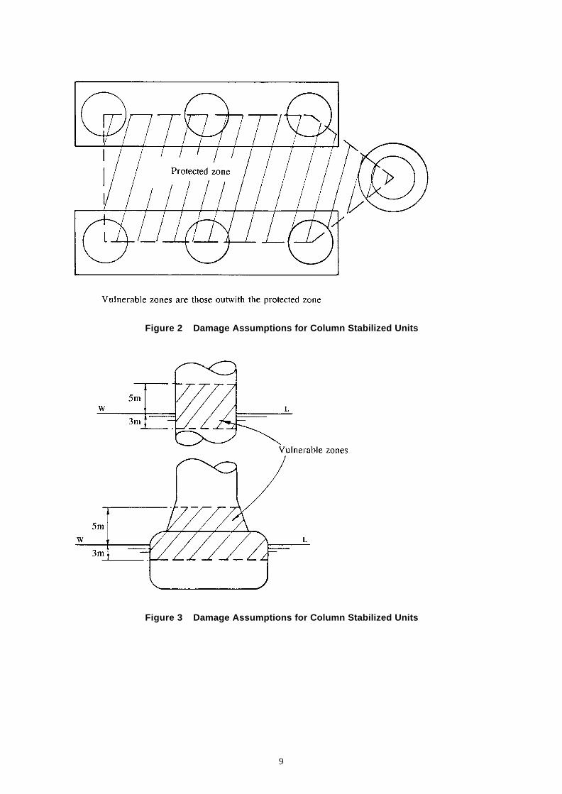
These two types of flooding may be assumed not to occur at the same time. Damage penetration should be assumed to occur anywhere within a vulnerable zone suggested to be:
extending 5 metres above to 3 metres below the draught under consideration, and to a depth of 1.5 metres in a horizontal direction perpendicular to the skin, with a lateral or circumferential extent of 3 metres and a vertical extent of 3 metres (see Figures 2 to 5).
Alternatively, for surface and self-elevating units, damage extent may be assumed to occur between effective watertight bulkheads as:
• horizontal penetration - 1.5 metres, and
• vertical extent - from the base line upwards without limit.
It is suggested that the distance between effective watertight bulkheads (or their nearest stepped portions) which are positioned within the assumed extent of horizontal penetration, should be not less than 3 metres. Where there is a lesser distance, one or more of the adjacent bulkheads should be disregarded. Where damage of lesser extent results in a more severe condition, this should also be taken into account. In the case of a self-elevating unit where a mat is fitted, the above extent of damage should be applied to both the platform and the mat, but not necessarily simultaneously unless considered necessary due to their close proximity.
9
Figure 2 Damage Assumptions for Column Stabilized Units
Figure 3 Damage Assumptions for Column Stabilized Units

10
Figure 4 Damage Penetration

11
Figure 5 Simultaneous Pontoon/Column Damage
Only those columns, footings or pontoons on the periphery of a column-stabilised unit need be assumed to be damaged, and the damage may be assumed to affect only their exposed portions (see Figures 2 to 5). (Note that other parts of columns, footings or pontoons should be considered to be subject to single compartment flooding as defined in a) above). Account may be taken of any protection afforded by anchor bolsters, as should the possibility of local structural failure of bolster-to-hull connections.

12
All piping, ventilation systems, trunks, etc. within the extent of damage referred to above should be assumed to be damaged. Positive means of closure should be provided at watertight boundaries to preclude the progressive flooding of other spaces which are intended to remain intact (see also Section 3). Such means of closure and their control should be located outside the damage penetration zone. Note: Reference to ‘damage’ elsewhere in this document should be taken to mean penetration damage and flooding. 2.5 PERMEABILITIES Permeability is the volume of a space available to flood. The following permeability values may be assumed:
• Storerooms 0.95
• Machinery spaces 0.85
• Accommodation spaces 0.95
• Tanks and voids 0.95
Other values can be used if adequately supported by calculations and if consistent with operating practice. 2.6 DAMAGED STABILITY CRITERIA Consideration should be given to providing the unit with sufficient reserve stability in damaged conditions to withstand the wind heeling moment based on a wind velocity of at least 25.8 metres per second (50 knots) imposed from any direction. In this condition the final waterplane after flooding, taking into account sinkage, trim and heel, will need to be below the lower edge of any opening through the external watertight boundary (see also Section 3.5). It is suggested that the area under the righting moment curve should be at least equal to the area under the 25.8 metres per second wind heeling moment curve - to an angle not exceeding either the angle of downflooding or the second intercept of the curves, whichever is the lesser. Both areas should be calculated from the static angle of heel without wind. For the purpose of calculating this area ratio, the angle of downflooding is defined as the angle at which any opening which does not comply with the requirements for closure of Section 3.5 reaches the water surface. The above criteria relate to stability margins and are based on quasi-static calculations. In a real seaway, openings above the damaged waterplane will be exposed to wave action, a situation further complicated by the dynamic response of the unit itself. These effects should be assessed to determine those areas liable to intermittent immersion. In the absence of any other information it is suggested that any opening which is positioned less than 4 metres above any damaged waterplane with the unit subject to steady wind heeling (as specified above) should be considered liable to intermittent immersion. Such openings should be protected by a closing appliance to a suitable weathertight standard (see Section 3.5). Consideration should be given to limiting the static angle of heel without wind to no more than 15.

13
Figure 6 illustrates the damaged stability criteria. Calculations should take into consideration the proportions and design characteristics of the unit and the arrangements and configuration of the damaged compartments. It should be assumed that the unit is in the worst anticipated service condition as regards stability and is floating free of mooring restraints.
* allowing for 4m wave clearance where appropriate (see Section 2.6)
Figure 6 Damaged Stability Criteria
The ability to reduce heeling angles by pumping out or ballasting compartments or by application of mooring forces, etc. should be disregarded for the purposes of calculation. However, see Section 4 for post-damage operability requirements for ballast systems of column stabilized units. At each draught, the calculations should be performed for a sufficient number of heeling directions to be able to identify the one most crit ical. This is where the maximum KG satisfying the criteria has its lowest value.

14
Suitable arrangements should be made to facilitate personnel access and escape up to the maximum angle anticipated after damage. Consideration should be given to including handrails to enable personnel to negotiate inclined corridors in accommodation areas and suitable handholds in control rooms, etc. which may be required to be manned in such conditions. It is suggested that grab rails be provided next to doors to assist personnel wishing to open or close them at large angles of inclination. Suitable arrangements should also be made to secure fixtures, fittings and loose equipment to prevent items from breaking loose and becoming a hazard in the event that the Installation takes on the maximum angle of heel after damage. For example, barriers should be provided to prevent the shifting of tubular goods on the pipe deck. Containers should be similarly secured. 2.7 KG LIMIT CURVES It is suggested that curves based on the preceding calculations indicating the limitations imposed on KG by the stability requirements in relation to draught and operating conditions should be plotted. These curves of maximum allowable KG should cover the complete draught range from light draught to maximum draught and consideration should be given to providing the following information:
a) A curve of maximum KG for compliance with the minimum GM (see Section 2.3) and intact stability criteria for a stated wind speed of not less than 51.5 metres per second (100 knots) and clearly labelled as relating to the intact severe storm condition.
b) A curve of maximum KG for compliance with the most critical of the following:
- intact stability criteria with a stated assumed wind speed not less than 36 - metres per second (70 knots); - compliance with the damaged stability criteria; - maintenance of required minimum GM in accordance with Section 2.3. This curve should be labelled to show that it relates to operating and transit conditions.
c) For column stabilized units, an additional curve for intermediate temporary conditions likely
to be experienced during ballasting transitions to and from operational, severe storm and transit draughts. This relates to intact stability with wind speeds of at least 36 metres per second (70 knots) and with relaxed GM requirements (ie. 0.3 metres), and to damaged stability with single compartment flooding (ie. as Section 2.4 a)) but disregarding the 15° limit on heel after flooding (see Section 2.6), in which case emergency equipment would need to continue to function at angles of inclination greater than 15°.
For column stabilized units, curves should be drawn to indicate the typical variation of KG with draught during ballasting from transit draught to severe storm draught and during deballasting from maximum operating draught to severe storm draught. It is suggested that the ordinates of these curves should not exceed the following:
• curve (a) above at severe storm draught;
• curve (b) above at operating and transit draughts; and
• curve (c) above at any draught.

15
These KG limit curves should not include any correction for free surface effects. Onboard calculations of actual KG should therefore include a correction for free surface effects before comparison with these curves. No statement about the variable load on board the unit should be marked on the allowable KG curves, since such data can become invalid due to subsequent changes to the lightship weight of the unit (see Section 2.1). For self-elevating units curve (a) would need to be labelled to show that it related to the Transit Severe Storm Condition, curve (b) would need to be labelled to show that it related to the Normal Transit Condition. Such a unit may be towed in the Normal Transit Condition provided that it can readily be brought to the Transit Severe Storm Condition should severe weather arise, otherwise the unit would need to comply with both criteria throughout the tow. For 'field moves' taking place within the period of an accurate and favourable weather forecast, a Field Move Condition can be specified corresponding to curve (b) but with relaxed stability range as in Section 2.3. Favourable weather would need to be taken to mean the combination of environmental factors which are within the limiting conditions for moving, lowering and elevating the unit from the floating condition. The circumstances in which the field move criteria can be adopted, would need to be described. It is suggested that towing afloat in any other circumstances (e.g. extended field moves) should not be undertaken unless there has been an independent assessment by competent persons for the proposed towing operation to establish environmental criteria in relation to the stability characteristic of the unit in the intended loading condition, and includes contingency arrangements for unexpectedly severe weather. Such an assessment should take due account of the information and instructions which describe the circumstances in which the field move criteria may be applied. Where necessary, separate allowable KG diagrams would need to be provided to cover the various leg length, leg elevation and footing conditions applicable to the transit mode, and any other changes in configuration having a significant effect on wind heeling moment (see Section 2.2). These requirements do not preclude the presentation of a single curve of allowable KG, which satisfies all of the above requirements. Any associated operating restrictions (e.g. minimum contents in ballast tanks etc.) should be clearly stated.

16

17
3. WATERTIGHT INTEGRITY 3.1 GENERAL RECOMMENDATIONS FOR WATERTIGHT INTEGRITY Watertight integrity should be maintained in specific compartments to meet intact and damaged stability criteria (see Section 2) and for other compartments that may need to be protected against water ingress for operational and safety reasons (e.g. accommodation spaces, control rooms, spaces containing safety equipment etc.). The number of openings in the boundaries of watertight compartments should be kept to a minimum compatible with the design and proper working of the unit. Where penetrations of these boundaries are necessary for access, piping, ventilation, electrical cables, etc., suitable arrangements should be made to maintain the strength of these boundaries and their watertight integrity. All watertight boundaries, associated closing appliances and their means of closure should be of sufficient strength and tightness of closure to withstand the pressure and other loads likely to occur in service and following damage (including wave impact loads). Established practice for ships can be used as a basis for the various requirements relating to closing appliances (e.g. heights of hatch coamings and door sills). However, the characteristics of Offshore Installations can differ significantly from those of conventional ships, particularly for column-stabilised and self-elevating units. Such practice should therefore only be applied to the extent that it remains valid for the intended circumstances. Manned control rooms in surface and column-stabilised units that include remote controls for ballast and bilge systems etc. (see Section 4) should be above any final waterplane after damage as defined in Section 2.6. Where reference is made to remote controls being in some other readily accessible position which is above any final waterplane after damage, such positions should be readily accessible in all intact and damage conditions and should be suitably protected, access being preferably from within the unit. Where reference is made to controls for valves, doors, hatches etc. the following general suggestions are applicable:
a) Remote controls and associated indicators should be situated in a manned control room. b) Unless required to be otherwise by c) below, remotely controlled closing appliances should
fail to a safe condition on loss of control power and remain so on restoration of control power. c) Remotely controlled access openings should have the following features to safeguard
personnel:
• a switch on the control panel in the control room which enables either ‘normal’ or ‘emergency’ mode to be selected;
• in ‘normal’ mode, control to be local without automatic re-closing (i.e. re-closing overridden);
• in ‘emergency’ mode, control to be remote and such that the doors close automatically when opened by local control;

18
• the ‘emergency’ mode should be restricted to emergency only use;
• with ‘normal’ mode selected, there should be a physical safeguard against accidental selection of ‘emergency’ mode;
• powered means of closure should be provided with local alarms, and closure speed should be limited to safeguard personnel;
d) Where closing appliances remain open on loss of control power, a separate remote means of
closure should be provided. In the case of valves this may be by manual mechanical means from another readily accessible position that is above any final waterplane after damage.
e) The status (open/closed) of each closing appliance should be indicated at each position from
which it may be controlled. f) Closing appliances and their controls, indicators, actuators, sources of power etc. should be
arranged to ensure that they remain capable of functioning effectively in emergency conditions, including damaged conditions.
Reference should be made to Sections 4 and 5 for the special areas that apply to ballast systems. Watertight doors and watertight hatches intended for personnel access or escape should be operable locally from both sides of the associated bulkhead or deck. 3.2 INTERNAL PIPES, DUCTS AND ASSOCIATED VAL VES Pipes and ducts should be routed to clear those areas that are vulnerable to penetration damage (see Section 2.4). When this is not possible, positive means of closure should be considered at watertight boundaries to prevent progressive flooding of other compartments intended to remain intact (see also Section 2.4). Where valves are required at watertight boundaries, they would need to be remotely operable from a manned control room or by mechanical means from another readily accessible position that is above any final waterplane after damage. These suggestions do not apply to valves that are required to be permanently closed while the unit is afloat, in which case the valve controls should be labelled accordingly and appropriate instructions made available to operatives. 3.3 INLETS, DISCHARGES AND ASSOCIATED VALVES Every inlet or discharge port submerged at maximum operating draught should be fitted with a valve that is remotely controlled from a manned control room. Each such valve should fail closed unless overriding safety considerations require it to remain open. Systems that would otherwise require their inlet/discharge valves to fail closed should not share a common inlet/outlet with systems that require these valves to fail to set. It is suggested each inlet or discharge port intended to fail to set should be provided with an independent secondary means of closure which could be by means of an independent remotely controlled device or by mechanical means from a readily accessible position above any final waterplane after damage.

19
Other discharge ports that penetrate boundaries into compartments intended to be watertight should be fitted with an automatic non-return valve, and with either a second such valve or a device whereby the port may be closed from a position outside and above the compartment. Such a position should remain readily accessible in all intact and damaged conditions. Discharge ports not submerged at maximum operating draught which serve closed systems need only be fitted with a locally closeable automatic non-return valve. 3.4 INTERNAL ACCESS OPENINGS To ensure the watertight integrity of internal access openings which are used during the operation of the unit, whilst afloat, consideration should be given to the following:
a) Doors (that would normally be of the sliding type) and hatch covers should be remotely controlled from a manned control room and should also be operable locally from each side of the watertight boundary. Indicators would need to be provided at the remote control position to indicate whether the doors are open or closed.
b) The requirements regarding these remote controls may be relaxed where those doors or hatch
covers are normally not used while the unit is afloat (i.e. emergency openings). However, an alarm system would need to be provided (e.g. light signals) showing personnel in the manned control room whether the doors or hatch covers in question are open or closed. A notice should be affixed to each such door or hatch cover to the effect that it is not to be left open while the unit is afloat.
3.5 EXTERNAL OPENINGS External openings need to remain completely above any waterplane associated with the unit being heeled due to wind forces in the intact condition (as defined in Section 2.2) as well as in the damaged condition defined in Section 2.6. Manholes fitted with close-bolted watertight covers (normally kept permanently closed while the unit is afloat) may be submerged. External openings which would become wholly or partially submerged in meeting the area ratio and range requirements for stability (as in Sections 2.3 and 2.6) or which may become intermittently submerged due to wave action in damaged conditions should be weathertight and compliance with the following is suggested:
a) Those openings which may become intermittently immersed in a damaged condition should be either self-closing in the event of immersion, or be otherwise readily and quickly closeable at any time, or it should be assumed in the damage stability calculations that flooding may occur through the opening. External openings which cannot be quickly closed, such as large hatches, should be assumed open in damage stability calculations unless (such as in the case of self-elevating units) the openings are to be permanently closed when the unit is afloat.
b) Doors and hatches that may be used during operation of the unit, while afloat, should be
equipped with closing appliances, which are operable locally from both sides of the bulkhead or deck. The status of closing appliances for doors or hatches which would become intermittently submerged after damage in meeting the requirements of Section 2.6 should also be remotely indicated in a manned control room. These doors and hatches should be self-

20
closing on immersion or readily and quickly closeable and should bear a notice to the effect that they are not to be left open during operation of the unit, while afloat.
c) Ventilators, ventilation intakes and outlets that may be used during operation of the unit,
while afloat, should incorporate a self-acting anti-flooding device. Those intakes or outlets which are not subject to intermittent submergence after damage in meeting the requirements of Section 2.6 may alternatively be fitted with a manually operated means of closure which is readily accessible.
d) Those closing appliances that are not to be opened during operation of the unit, while afloat,
should bear a notice to that effect. e) Air pipes should incorporate an anti-flooding device. f) Side scuttles and windows should be of the non-opening type fitted with internal hinged
deadlight covers. The numbers of such fittings in areas vulnerable to wave impact (e.g. the columns of column stabilized units) should be reduced to the absolute minimum. Consideration should be given to providing instructions for the closure of deadlights in storm conditions.
g) Chain locker openings in column-stabilised units should be fitted with weathertight closing
appliances that are remotely operable from the ballast control room. Such devices may be dispensed with if the chain lockers are kept full of water, or are free-flooding, or are provided with an active de-watering system of sufficient capacity which remains operable in all intact and damaged conditions of the unit.
h) All of the above closing appliances should be able to withstand wave impact loads. These
should be estimated so that the adequacy of proposed fittings can be assessed, as the impact pressures may exceed the strength of fittings selected in accordance with normal ship practice (see Section 3.1).
Any other external opening leading to spaces, the buoyancy of which is included to meet stability requirements, should be fitted with a weathertight-closing appliance that complies with applicable load-line requirements. On column-stabilised and self-elevating units, such appliances should be deemed to be ‘Position 1’ regardless of their position in relation to any deck deemed to be the freeboard deck. For chain locker openings compliance with g) above is suggested. In the case of self-elevating units some dispensations may be made with respect to the requirements for closures to openings which would become submerged at the larger angles of heel associated with the range defined by stability requirements (Section 2.3), recognising the notional nature of these waterplanes. 3.6 FLOODING ALARMS Every compartment required to remain watertight in meeting the intact and damaged stability criteria (Section 2) should incorporate a suitably positioned device to detect flooding and provide an alarm in a manned control room. This will not be necessary for tanks having contents gauges which register in the manned control room, or for small compartments the flooding of which would have a negligible effect on stability. Consideration should be given to providing pump rooms, propulsion rooms etc. in

21
the pontoons, footings or columns of column-stabilised units with two independent, low-level and high-level bilge alarms.

22

23
4. BALLASTING To enable normal operations to carry on safely, the unit would need to be provided with a ballasting system that is capable at any time of efficiently trimming and adjusting the draught of the unit. This is intended to meet the stability implications of Section 2 maintaining level trim. Ballast tanks and associated equipment would need to be in accordance with the relevant provisions of classification rules such as those in Reference 5; column-stabilised units would also need to comply with Section 5 below. 4.1 BILGE PUMPING SYSTEMS All units when afloat would need to have adequate bilge pumping systems and means of draining all compartments and watertight sections. Compartments used for containing liquids should have their own separate pumping and drainage system. The capacity and arrangement of the system would need to follow the relevant provisions of classification rules such as those in Reference 5 (see also Section 3.6).

24

25
5. BALLAST SYSTEMS FOR COLUMN STABILIZED UNITS The nature of column-stabilised units renders them particularly vulnerable to faults that could occur in their ballast systems. It is also highly desirable for ballast systems to be able to function at the angles of heel which may be experienced as a result of the accidental flooding or filling of watertight compartments to enable countermeasures to be taken. It is suggested that the ballast system should be designed and arranged such that, with the unit intact and inclined by up to 5° in any direction, it can take suction from any ballast tank and execute any necessary ballast changes in a reasonable period of time. The system would need to be capable of deballasting from maximum operating draught, either a distance of 4.6m (15 feet) or to the survival draught, whichever distance is greater, within 3 hours. 5.1 BALLAST CONTROL ROOM Consideration should be given to arranging the system to have centralised remote control from a manned control room that incorporates:
a) Remote controls and indicators for ballast pumps and ballast and sea chest valves. b) Contents gauges for ballast and other tanks. c) Instruments for indicating draught and inclination. d) Alarms to indicate fault conditions, including an audible and visible alarm to indicate the
failure of any power supply to the system. e) Power availability indicating system (main and emergency). f) Ballast system hydraulic/pneumatic pressure indicating system (including pressure in
hydraulic return or vent lines). g) Means to isolate or disconnect the ballast valve control systems from their sources of
electrical, pneumatic or hydraulic power. h) Bilge and flood alarms (see also Section 3.6). i) Bilge pump controls. j) Remote controls and indicators for watertight closing appliances (see also Section 3). k) Instruments for monitoring mooring line tension (see also Section 2). l) Facilities for internal communication.
Items a) and i) would need to be incorporated in a display (which may be in the form of a mimic panel) which represents the workings of the system. The orientation of the display or panel should correspond to that of the unit.

26
The central ballast control station and any back-up stations should be located such that they are readily accessible and protected from weather when the unit is subjected to the most severe intact and damaged conditions identified in Section 2. The central ballast control station should also remain above any final waterplane after damage (as identified in Section 2.6). In addition to remote control of the ballast pumps and valves from the central ballast control station, all ballast pumps and valves need to be fitted with permanently installed independent local control operable in the event of remote control failure. The independent local control of each ballast pump and of its associated ballast tank valves should be in the same location, and a diagram representing the workings of that part of the system should be permanently installed at each such location. The local controls should be in readily accessible positions, and the associated access routes should not be situated within the damage penetration zones identified in Section 2. All controls should be clearly labelled to identify the associated device. Positive indication of actual valve position (open/shut) should be provided at each valve control position. A permanently installed means of communication that remains operable in the event of failure of the main electrical supply should be provided between the central ballast control station and those spaces containing the local controls for ballast pumps and valves, or other spaces that may contain equipment necessary for the operation of the ballast system. 5.2 BALLAST SYSTEM REDUNDANCY The ballast system needs to be designed and constructed so that, in the event of the failure of any single component, the remainder of the system continues to be capable of effective operation (i.e. to permit trimming and adjustment of the draught of the unit). Examples of single components subject to failure are: pumps and their power supplies, valves and their actuators (including their power sources), and controls for pumps and valves (including their power sources). In particular, the following suggestions are made:
a) It is important to maintain the independence of control and indication systems. Centralised remote controls for ballast pump control, ballast valve control, valve position indication, tank level indication, and draught indication, should therefore function independently of one another such that a failure in one system will not cause malfunction or loss of operation of any of the other systems.
b) At least two independent ballast pumps should be capable of taking suction on each ballast
tank. c) Ballast pump and ballast valve control systems should be designed and arranged such that the
loss of any one component in the control system will not result in loss of operation of other pumps and valves.
d) Where microprocessor or computer operated or multiplex type systems are installed,
secondary or redundant control systems should be provided to ensure continued operational capability.

27
e) The system should be operable from two independent sources of power, at least one of which should remain available following a damage/flooding incident (see Section 5.5) (e.g. emergency source of power).
It would need to be demonstrated (for example by failure effect analysis) that the system has been designed to prevent uncontrolled transfer of water between tanks or through sea-connected inlets or discharges in the event of single failures, such as:
• the failure of any single valve or valve actuator;
• any single failure in the means of control or indication, including loss of power to control or indication systems or for valve actuation, or internal leakage in hydraulic control systems;
• the flooding of any space containing equipment associated with the ballast system, in which the risk of flooding is present.
5.3 BALLAST SYSTEM SAFETY FEATURES It is suggested that the ballast system should also incorporate the following specific safety features:
a) Valves that enable the transfer of ballast should close automatically on loss of control or actuating power (but see also Section 3.3 for inlet valves that may not necessarily fail closed).
b) Communication between any two tanks or between any tank and the sea should be via at least
two independently remotely controlled valves. c) Ballast manifolds should be arranged such that water cannot be transferred from one end or
side of the unit to the other without the initiation of a special operational procedure. d) The system should be arranged such that in the event of a burst pipe in any part of the system
connected to the sea, the flooding can be brought quickly under control. In particular, sea chest valves should either fail closed or be backed up by a second valve having independent remote control (see also Section 3). Consideration should be given to the need for equipment to operate when submerged.
e) Upon reactivation of control power, those valves intended to close upon loss of control power
should remain closed until the ballast control operator assumes control of the reactivated system.
Special attention should be paid to system controls to eliminate the possibility of any valve or pump being inadvertently activated by a system fault or by any external system interference. All ballasting operations should be initiated by the ballast control operator unless overriding operational requirements dictate that the system be automatically controlled. Where the system is arranged for automatic or semi-automatic control (e.g. by microprocessor), particulars of the control system and its program logic may need to be reviewed.

28
5.4 BALLAST SYSTEM COMPONENTS AND EQUIPMENT Ballast pumps should normally be self-priming unless it can be demonstrated that this would be unnecessary for the intended application. Electrical control equipment should be suitable for the environment in which it is situated (e.g. weatherproof). Where practicable, ballast system equipment, including associated circuits and piping, should not be situated within the damage penetration zones identified in Sections 2 and 3. The closing speed of valves should, if necessary, be limited to prevent excessive pressure surges. Any associated restrictions on adjustment should be indicated. The ballast system should be designed to enable equipment to be maintained without rendering the system inoperable. All tanks should be provided with effective sounding arrangements (e.g. sounding pipes). In addit ion to these, consideration should be given to providing remote indicating level gauges for:
• all ballast tanks;
• other tanks subject to flooding in accordance with the extent of damage/flooding assumed for the purposes of Section 2 unless the effect on stability would be insignificant;
• any other tanks, the contents of which would need to be closely monitored from the ballast control room for effective ballasting.
Where practicable, level gauges should be positioned to minimise inaccuracy induced as a result of inclination of the unit. Otherwise suitable warnings about limitations on accuracy should be provided. (Note also the considerations for flooding and bilge alarms in other spaces as given in Section 3). Air pipes should be self-draining under all normal conditions of trim, and the tank contents sensing method should not be by comparison of pressure head at the bottom of the tank with atmospheric pressure. Reference should be made to Sections 2 and 3 for location and closure requirements for venting and sounding pipes necessary to maintain the watertight integrity of the unit. Air pipes should be provided in each ballast tank sufficient in number and cross-sectional area to permit the efficient operation of the ballast pumping system in all required conditions. In order to allow deballasting of certain tanks to achieve the recovery objectives identified in Section 5.5, the air pipe openings of such tanks should remain above any final damage waterplane as defined in Section 2.6, and should not be situated within the damage penetration zones defined in Section 2. Pump suctions should be suitably positioned to enable tanks to be emptied effectively. The internal structure of tanks should incorporate air holes and limber holes as necessary for efficient venting and flow to suction pipes. Suitable equipment should be provided to allow draught and inclination to be monitored at the central ballast control station to the accuracy necessary to permit stability calculations to be performed, and

29
for monitoring the effects of ballast changes. The equipment should remain operable despite the effects of waves and resulting motions of the unit, and after any damage/flooding assumed in Section 2. However, it is not intended that such accuracy be maintained in storm conditions. Pump rooms should be provided with an emergency bilge suction, which may be by means of a connection to the ballast system provided that there are suitable safeguards against accidental flooding through the associated suction line. 5.5 SYSTEM CAPABILITY FOLLOWING DAMAGE OR FLOODING The ballast system (including pumps, valve actuators, valve position indicators, tank contents gauges, flooding and bilge alarms, draught and inclination indicators, their various power sources, and any other ballast system control equipment) should be designed to be capable of operating in the event of any damage/flooding as discussed in Section 2 to the extent necessary to enable the system to recover the unit to a condition of level trim at maximum operating draught, whilst not exceeding maximum damage displacement and within a reasonable period of time. The system should have this capability with any one pump inoperable. It should be noted that such conditions will include the flooding of pump rooms, and any o ther physical damage to the ballast system arising from the damage/flooding conditions. This capability may be achieved by means of a secondary deballasting system. The system should be capable of meeting this objective by pumping, i.e. recovery should n ot depend upon counter-flooding, even though in practice this may remain a valid option in an emergency. For design purposes it should be assumed that the unit has reached its final equilibrium position after damage as identified in Section 2.6 before countermeasures are taken. Procedures for recovery should be worked out to demonstrate the capability of the system. As part of a damage control plan, details of these recovery procedures including their duration and any precautions to be taken to maintain adequate stability during recovery should be provided. Where pumps are required to operate under adverse pressure conditions, care should be taken to ensure that the pumps have an adequate margin to prevent severe loss of performance.

30

31
6. REFERENCES 1. Department of Energy. Offshore Installations: Guidance on Design, Construction and
Certification, 4 th Edition. HMSO, Consolidated Edition, 1993 (plus Amendment No. 3, 1995). [Withdrawn 1998 by Operations Notice 27].
2. SI 1974 / 289 – The Offshore Installa tions (Construction and Survey) Regulations 1974,
HMSO, 1974. [Revoked and has been replaced by SI 1996 / 913 – The Offshore Installations and Wells (Design and Construction etc.) Regulations, 1996 – ISBN: 0 110 54451 X].
3. Health and Safety Executive. Status of Technical Guidance on Design, Construction and
Certification. Operations Notice 27. Revised and Reissued, August 1998. 4. Department of Energy. A Study of Methods of Measuring the Metacentric Heights of Semi-
submersibles. OTH Report 84 211. 5. Det Norske Veritas. Rules for Classification of Mobile Offshore Units.

32

33

Printed and published by the Health and Safety ExecutiveC0.50 06/02
OTO 2001/049
£10.00 9 780717 625086
ISBN 0-7176-2508-7