off-site site plan brooklyn terminal rcs site plan on remediation... · global remediation 464...
TRANSCRIPT
ExxonMobil Refining & Supply Company Global Remediation 464 Doughty Boulevard Inwood, New York 11096
MC17230Y21.935/CL
September 28, 2007
New York State Department of Environmental Conservation Division of Environmental Remediation Remedial Bureau D 625 Broadway 12th Floor Albany, New York 12233-7013 Attn. Mr. Joseph White
Ref: SPDES Equivalency ExxonMobil Off-Site and Brooklyn Terminal Groundwater Treatment Systems S224087 / S224088 Greenpoint, Brooklyn, New York
Dear Mr. White:
Attached in response to the New York State Department of Environmental Conservation’s June 22, 2007 letter relating to the subject SPDES Equivalency is an Engineering Plan outlining the methodology that will be used to evaluate and identify necessary upgrades to the treatment facilities to meet the most environmentally protective level found in either the Division of Water Technical & Operational Guidance Series (TOGS) 1.2.1, Attachment C, or the Guidance for Petroleum Spill Stipulation Agreement. The Engineering Plan Systems Evaluation Report will be due September 28, 2008.
Should you have any questions please contact me at 516-239-5232.
Sincerely,
Steve P. Trifiletti Project Manager
Attachment
cc: Regional Water Engineer (NYSDEC Region 2) - Long Island City, NY NYSDEC Section Chief, Wastewater Permits South, Division of Water – Albany, NY Ed Hampston – NYSDEC Alan Fuchs – NYSDEC Justin Kennedy - Roux Associates, Inc. Andrew Baris - Roux Associates, Inc.
Remedial Engineering, P.C. Environmental Engineers
and ROUX ASSOCIATES, INC. 209 Shafter Street, Islandia, New York 11749 ♦ 631-232-2600
MC17230Y21.935/CV
September 28, 2007 ENGINEERING PLAN FOR THE EVALUATION OF TREATMENT SYSTEM PERFORMANCE AND NECESSARY FACILITY UPGRADES Greenpoint Remediation Project Prepared for:
EXXONMOBIL REFINING AND SUPPLY COMPANY 400 Kingslands Avenue Brooklyn, New York 11222
REMEDIAL ENGINEERING ,P.C. - i - MC17230Y21.935/R
TABLE OF CONTENTS
1.0 INTRODUCTION ....................................................................................................................1
2.0 DESCRIPTION OF TREATMENT SYSTEMS ......................................................................2 2.1 Off-Site System ...................................................................................................................2 2.2 Brooklyn Terminal RCS .....................................................................................................3 2.3 Installation of Additional Off-Site Recovery Wells ...........................................................5
3.0 COMPARISON OF CURRENT LIMITS AND SYSTEM PERFORMANCE WITH FUTURE TREATMENT GOALS .................................................6
4.0 ANALYSIS OF INTERIM MEASURES TO IMPROVE TREATMENT ..............................8
5.0 METHODOLOGY FOR EVALUATING POTENTIAL FACILITY UPGRADES .............10 5.1 Additional Data Collection ...............................................................................................10 5.2 Identification and Screening of Potentially Applicable Technologies .............................11 5.3 Detailed Evaluation of Technologies and Operational Scenarios .....................................12 5.4 Selection and Preliminary Design of Upgrades ................................................................12
6.0 ENGINEERING REPORT .....................................................................................................13
TABLES 1. Comparison of Discharge Limits with Future Treatment Goals and Historic Effluent
Concentrations: Off-Site Free-Product Recovery System 2. Comparison of Discharge Limits with Future Treatment Goals and Historic Effluent
Concentrations: ExxonMobil On-Site Recovery and Containment System
APPENDIX A. Air Stripper Model Output for Proposal Off-Site Air Strippers
FIGURES 1. Site Plan 2. Off-Site Site Plan 3. Off-Site Water Treatment Process Flow Diagram 4. Brooklyn Terminal RCS Site Plan 5. Brooklyn Terminal RCS Water Treatment Process Flow Diagram

REMEDIAL ENGINEERING, P.C. - 1 - MC17230Y21.935/R
1.0 INTRODUCTION On behalf of ExxonMobil Refining and Supply Company (ExxonMobil), Remedial Engineering,
P.C. (Remedial Engineering) in association with Roux Associates, Inc. (Roux Associates) has
prepared this Engineering Plan for the Evaluation of Treatment Facility Upgrades (Engineering
Plan) for ExxonMobil’s groundwater treatment facilities in Greenpoint, Brooklyn, New York.
The facilities that are the subject of this evaluation are the treatment facilities for the
ExxonMobil Off-Site Free-Product Recovery System (Off-Site System) and the ExxonMobil
Brooklyn Terminal (On-Site) Recovery and Containment System (RCS). As specified in
Additional Condition 9 of the SPDES Equivalency Letter dated June 22, 2007, from the New
York State Department of Environmental Conservation (NYSDEC) to ExxonMobil, the
objectives of the Engineering Plan are to:
• Outline the methodology that will be used to evaluate and identify necessary upgrades to the treatment facilities with a goal to meet the most environmentally protective level found in either the Division of Water Technical & Operational Guidance Series (TOGS) 1.2.1, Attachment C, or the Guidance for Petroleum Spill Stipulation Agreement (GPSSA); and
• Provide an analysis of any interim measures, either operational or equipment oriented, which would assist the facility in reducing the discharge of contaminants toward the levels specified in the above referenced documents.
This Engineering Plan has been prepared to provide the following information:
• A description and history of the existing treatment facilities;
• A comparison of proposed treatment goals (e.g., TOGS 1.2.1 Appendix C and GPSSA) with current SPDES-equivalent discharge limits and current / historical system performance;
• An analysis of interim measures that may improve treatment performance; and
• The scope of work that will be implemented to identify additional upgrades that may be necessary to meet the potential future treatment goals (i.e., the most environmentally protective levels found in TOGS 1.2.1 Attachment C, or GPSSA).
REMEDIAL ENGINEERING, P.C. - 2 - MC17230Y21.935/R
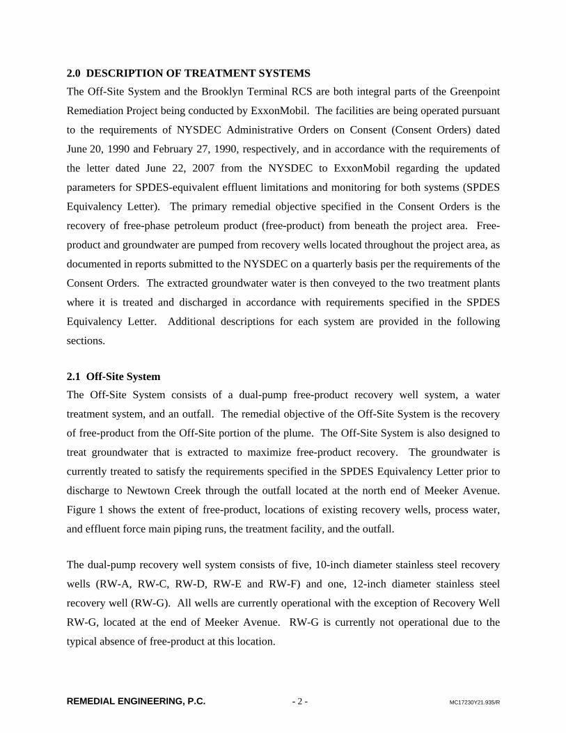
2.0 DESCRIPTION OF TREATMENT SYSTEMS The Off-Site System and the Brooklyn Terminal RCS are both integral parts of the Greenpoint
Remediation Project being conducted by ExxonMobil. The facilities are being operated pursuant
to the requirements of NYSDEC Administrative Orders on Consent (Consent Orders) dated
June 20, 1990 and February 27, 1990, respectively, and in accordance with the requirements of
the letter dated June 22, 2007 from the NYSDEC to ExxonMobil regarding the updated
parameters for SPDES-equivalent effluent limitations and monitoring for both systems (SPDES
Equivalency Letter). The primary remedial objective specified in the Consent Orders is the
recovery of free-phase petroleum product (free-product) from beneath the project area. Free-
product and groundwater are pumped from recovery wells located throughout the project area, as
documented in reports submitted to the NYSDEC on a quarterly basis per the requirements of the
Consent Orders. The extracted groundwater water is then conveyed to the two treatment plants
where it is treated and discharged in accordance with requirements specified in the SPDES
Equivalency Letter. Additional descriptions for each system are provided in the following
sections.
2.1 Off-Site System The Off-Site System consists of a dual-pump free-product recovery well system, a water
treatment system, and an outfall. The remedial objective of the Off-Site System is the recovery
of free-product from the Off-Site portion of the plume. The Off-Site System is also designed to
treat groundwater that is extracted to maximize free-product recovery. The groundwater is
currently treated to satisfy the requirements specified in the SPDES Equivalency Letter prior to
discharge to Newtown Creek through the outfall located at the north end of Meeker Avenue.
Figure 1 shows the extent of free-product, locations of existing recovery wells, process water,
and effluent force main piping runs, the treatment facility, and the outfall.
The dual-pump recovery well system consists of five, 10-inch diameter stainless steel recovery
wells (RW-A, RW-C, RW-D, RW-E and RW-F) and one, 12-inch diameter stainless steel
recovery well (RW-G). All wells are currently operational with the exception of Recovery Well
RW-G, located at the end of Meeker Avenue. RW-G is currently not operational due to the
typical absence of free-product at this location.

REMEDIAL ENGINEERING, P.C. - 3 - MC17230Y21.935/R
Each operating recovery well is equipped with a two-pump system comprised of a water-table
depression pump to extract groundwater and a product recovery pump to remove the free-
product as it enters the well. The groundwater pumped from each well is conveyed through a
well house or an underground valve pit for local monitoring and control of the recovery well
water flow rate. The process water from each well is then combined with the flow from the other
wells into 4-inch and 6-inch cement-lined ductile iron underground force mains that ultimately
convey the water to the treatment facility (see Figure 2). The recovered free-product from each
operating recovery well is pumped to local 4,000 gallon fiberglass reinforced plastic (FRP),
double-walled underground storage tanks (USTs) installed at each well.
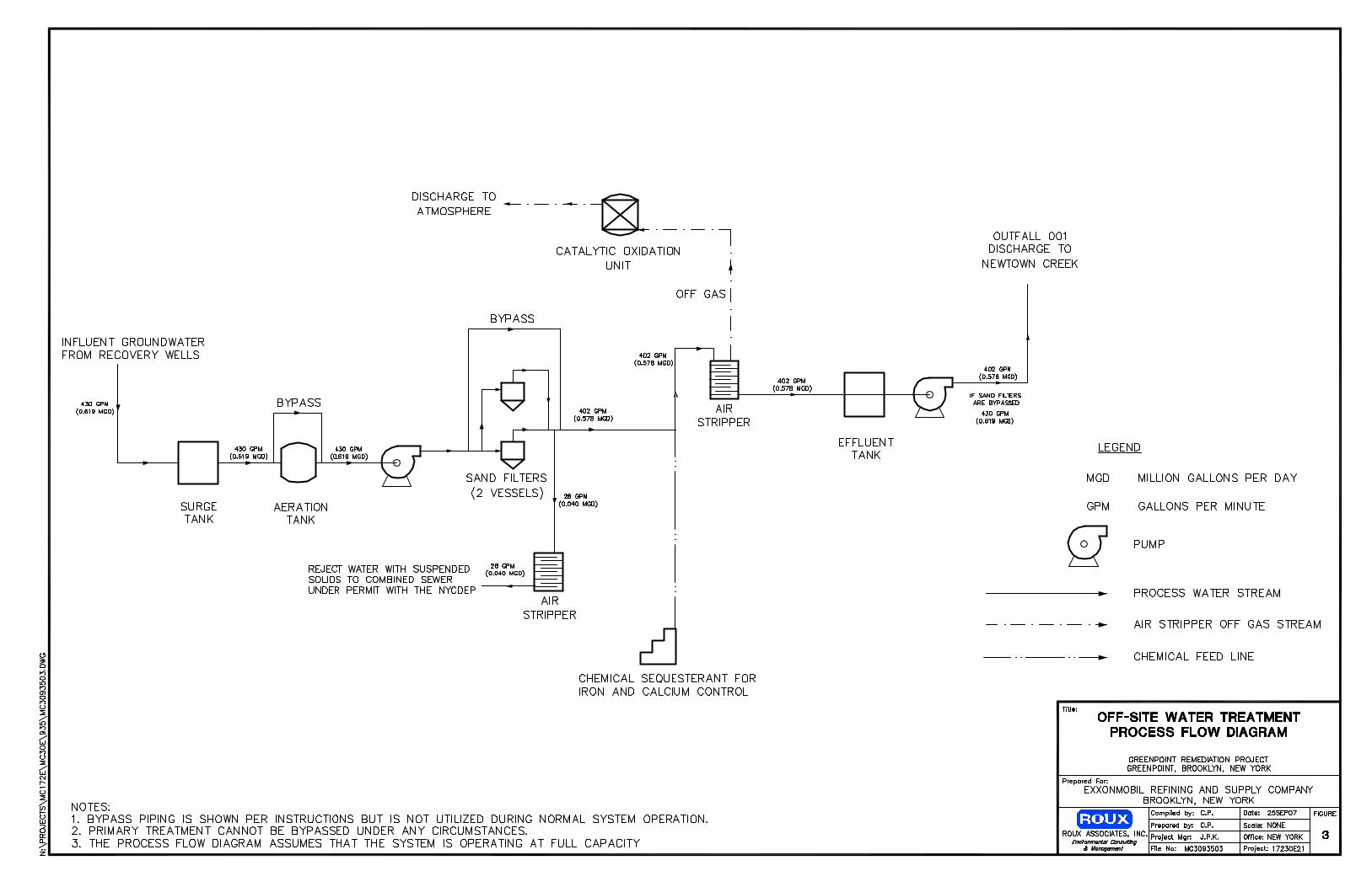
As noted above, groundwater extracted during free-product recovery operations is sent to the
Off-Site System treatment building. The groundwater treatment system includes the following
processes:
• Equalization;
• Iron removal;
• Volatile organic compound (VOC) and semivolatile organic compound (SVOC) removal;
• Off-gas treatment; and
• Filter backwash water VOC / SVOC removal.
Figure 3 provides a line diagram of flow through the treatment system.
The Off-Site System was designed for continuous operation, 24-hours a day, seven days a week,
at a total operating water flow rate of 430 gallons per minute (gpm). This includes the operation
of the existing System recovery wells at their design flow rates, plus extra capacity to allow for
the installation of additional recovery wells. The System currently operates at an overall flow
rate of less than 200 gpm, which maintains redundancy for most major system components and
thus reduces downtime.
2.2 Brooklyn Terminal RCS Similar to the Off-Site System, the RCS also consists of a dual-pump free-product recovery well
system, a water treatment system, and an outfall. The remedial objective of the System is the
REMEDIAL ENGINEERING, P.C. - 4 - MC17230Y21.935/R
recovery of free-product from the portion of the free-product plume present beneath the
Brooklyn Terminal and the former Brooklyn Refinery properties. The System is also designed to
treat groundwater that is extracted to maximize free-product recovery. The groundwater is
currently treated to satisfy the requirements specified in the SPDES Equivalency Letter prior to
discharge through the outfall to Newtown Creek located in the northeast corner of the 400
Kingsland Avenue property. Figure 1 shows the extent of free-product, locations of existing
recovery wells, process water force main piping runs, the treatment facility, the discharge piping
and the outfall.
The dual-pump recovery well system consists of four, 12-inch diameter stainless steel recovery
wells (RW-14, RW-17, RW-18, and RW-19). In addition to the four dual-pump recovery wells,
there is also one passive free-product recovery well (RW-20), which only recovers free-product
and does not pump and treat groundwater. All dual-pump wells are currently operational.
Each operating dual-pump recovery well is equipped with a two-pump system comprised of a
water-table depression pump to extract groundwater and a product recovery pump to remove the
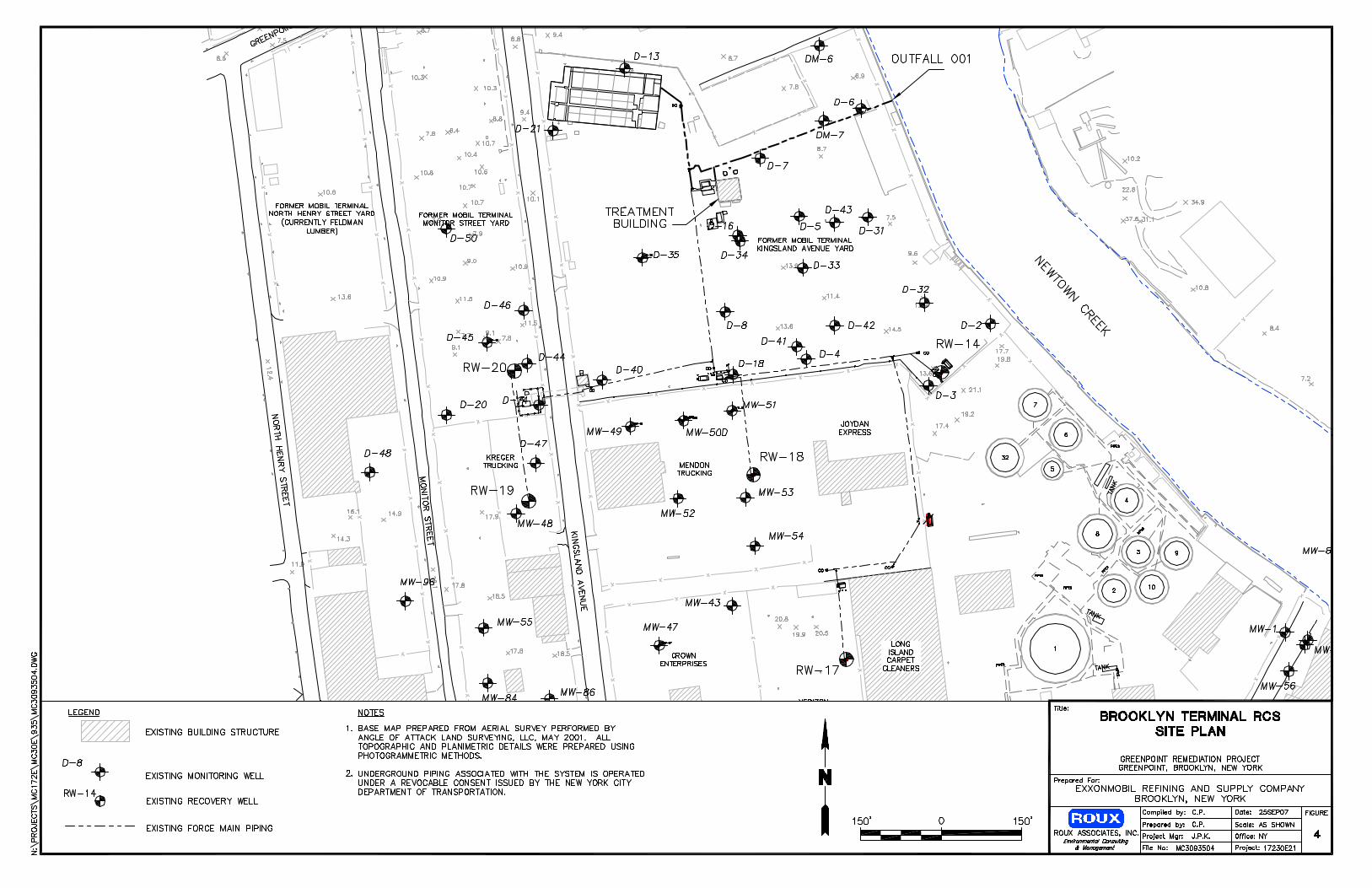
free-product as it enters the well. The groundwater pumped from each well is conveyed through
a well house for local monitoring and control of the recovery well water flow rate. The process
water from each well is then combined with the flow from the other wells in a 6-inch high-
density polyethylene (HDPE) force main that ultimately conveys the water to the treatment
facility (see Figure 4). The recovered free-product from each operating recovery well is pumped
to local aboveground storage tanks (ASTs) installed at each well or at a nearby location.
As noted above, groundwater extracted during free-product recovery operations is sent to the
RCS treatment building. The RCS treatment building also receives up to 100 gpm of
groundwater pumped by the BP remediation systems. The groundwater treatment system
includes the following processes:
• Oil/water separation;
• Equalization;
• Filtration;
REMEDIAL ENGINEERING, P.C. - 5 - MC17230Y21.935/R
• Volatile organic compound (VOC) and semivolatile organic compound (SVOC) removal; and
• Off-gas treatment.
The effluent from the groundwater treatment system is then combined with the stormwater
piping from the Site, run through the stormwater filtration system, and discharged to Newtown
Creek.
Figure 5 provides a line diagram of flow through the treatment system.
The System was designed for continuous operation, 24-hours a day, seven days a week, at a total
operating water flow rate of 450 (gpm). This includes the operation of the existing System
recovery wells at their design flow rates, plus extra capacity to allow for the installation of
additional recovery wells. The System currently operates at an overall flow rate of less than 200
gpm, which maintains redundancy for most major system components and thus reduces
downtime.
2.3 Installation of Additional Off-Site Recovery Wells As documented in previous reports and the SPDES applications submitted to the NYSDEC, an
additional ten recovery wells are in the process of being added to the Off-Site portion of the
Greenpoint Remediation Project area. The design and construction work associated with the
addition of these recovery wells is ongoing. It is anticipated that the construction of the ten
recovery wells and the associated process water force main to the water treatment facilities will
be completed during 2008, pending timely receipt of required permits and approvals for all
aspects of the work.
The combined flow rates from the existing and proposed additional recovery wells are within the
design capacity of the existing water treatment facilities and are included in the flow rates and
volumes provided with the current SPDES applications.
REMEDIAL ENGINEERING, P.C. - 6 - MC17230Y21.935/R
3.0 COMPARISON OF CURRENT LIMITS AND SYSTEM PERFORMANCE WITH FUTURE TREATMENT GOALS The current effluent limits for the Off-Site System and the Brooklyn Terminal RCS are specified
in the SPDES Equivalency Letter dated June 22, 2007. Based upon the SPDES Equivalency
Letter, potential future treatment goals will correspond to the most environmentally protective
levels found in either TOGS 1.2.1 Attachment C or the GPSSA.
The current effluent limits and potential future treatment goals for the Off-Site System and RCS
are summarized in Tables 1 and 2, respectively. These tables also provide a comparison of the
current effluent limits and the potential future treatment goals with the typical effluent quality
from each system. The typical effluent quality is shown as the long-term average concentrations
and the 95th percentile concentrations, which were determined based upon the three previous
years and two previous years of discharge monitoring presented in the SPDES applications that
were submitted to NYSDEC on May 10, 2007 for the Off-Site and RCS, respectively.
A review of Table 1 indicates that the Off-Site System long-term average effluent concentrations
and 95th percentile concentrations have been in compliance with existing limits. Comparison of
these concentrations with TOG 1.2.1 and GPSSA treatment objectives generally indicates that
current system performance achieves the potential future treatment goals for the majority of the
parameters. The primary exception is benzene, where the long term average of 13 micrograms
per liter (µg/L) exceeds the TOGS 1.21 and GPSSA treatment objectives of 5 and 7 µg/L,
respectively. At the 95th percentile concentrations, a few other VOCs exceed the TOGS and
GPSSA treatment objectives. The typical concentrations of total suspended solids (TSS) also
slightly exceed the “most environmentally protective” limit in TOGS 1.2.1 (corresponding to
treatment using lime, settle and filter technology).
Review of Table 2 indicates that the RCS long-term average effluent concentrations and 95th
percentile concentrations have been in compliance with existing limits. Comparison of these
concentrations with TOG 1.2.1 and GPSSA treatment objectives generally indicate that current
REMEDIAL ENGINEERING, P.C. - 7 - MC17230Y21.935/R
System performance achieves the potential future treatment goals for all parameters with the
exception of MTBE, which slightly exceeds the GPSSA treatment objective. At the 95th
percentile concentrations, TSS also slightly exceeds the “most environmentally protective” level
in TOGS 1.2.1.

REMEDIAL ENGINEERING, P.C. - 8 - MC17230Y21.935/R
4.0 ANALYSIS OF INTERIM MEASURES TO IMPROVE TREATMENT As noted in Section 3, both the Off-Site System and the RCS maintain full compliance with the
existing limits. The effluent from Off-Site System, while still in compliance with existing limits,
does not currently meet potential future treatment goals for benzene and a few other VOCs. The
RCS currently meets all of the potential future treatment goals for VOCs with the exception of
MTBE due to the concentration of MTBE in the groundwater extracted from beneath the BP
property.
The primary treatment for removal of VOCs at each of the treatment facilities is air stripping,
which is recognized as best available technology for removal of the petroleum-related VOCs
present in the extracted groundwater. At the Off-Site System, due to the age (12 years old) of the
existing two-unit air stripper system and the desire to minimize system downtime for
maintenance resulting from the additional flow from the proposed recovery wells, the two-unit
air stripper system is being replaced in September / October 2007 with a new three-unit air
stripper system (of similar design and technology). The new, three-unit air stripper system will
provide an equivalent or superior level of treatment and allow for offline maintenance of one air
stripper unit to proceed while the two other air strippers remain in operation.
The existing air strippers consist of three-tray ShallowTrayTM units, Model 31231, manufactured
by North East Environmental Products of Taunton, Massachusetts. The replacement air strippers
will consist of six-tray EZ-Tray units, Model 24.6, manufactured by QED Environmental of Ann
Arbor, Michigan. Modeling of the performance of the new units scheduled for installation
suggests that they will achieve greater removal of VOCs than the existing strippers. A copy of
the air stripper model output for the proposed air strippers is provided in Appendix A. Based
upon the modeling results, it is possible that the new air strippers will achieve the potential future
treatment goals. Therefore, the air stipper replacement and addition of the third air stipper has
been identified as the most important interim measure to improve treatment at the Off-Site
System towards the potential future treatment goals. As stated above, this interim measure is
currently being implemented with expected completion during November 2007.
The two air strippers at the RCS, also six-tray, Model 24.6 EZ-Tray units, were purchased new
and installed in 2004 when this system was constructed. However, the installation of a third air
REMEDIAL ENGINEERING, P.C. - 9 - MC17230Y21.935/R
stripper unit is proposed to allow for operation of two strippers concurrently while offline
maintenance of one air stripper unit proceeds without shutting down the system. The addition of
the third air stripper unit at the RCS is scheduled to occur in 2008 prior to the activation of the
additional recovery wells.
Another interim measure to improve VOC removal at both systems includes the modification of
the existing air / water operation ratios for the existing / new air strippers. Theoretically,
increasing the air flow rate through an operating air stripper relative to the incoming water flow
rate increases stripping efficiency. In order to implement this interim measure, a performance
assessment would have to be conducted in which the air flow rates through the existing air
strippers would be progressively increased in uniform steps above the normal air flow rate to
increase the air / water ratio. System process water samples would be collected during each step
from the system / air stripper influent and air stripper effluent to quantify the change in treatment
caused by each air flow rate change. Following completion of the performance assessment, air
stripper operation will be modified to utilize the air flow rate that provides the most efficient air /
water ratio.
In addition to the VOCs noted above, the existing data suggest the RCS and Off-Site System
treatment facilities may not be able to meet the “most environmentally protective” levels for
TSS; and that the Off-Site System may not currently be able to meet the “most environmentally
protective” limit for copper. Note that in each of these cases, the corresponding technology cited
by TOG 1.2.1 Appendix C is typically a metals precipitation / filtration process that is not in
place at either system, and may not be feasible for installation at the Off-Site System. As an
interim measure, ExxonMobil will review operational practices for the existing aeration /
filtration processes at the Off-Site System and the bag filtration process at the RCS to ensure
optimal utilization of these existing treatment components.
REMEDIAL ENGINEERING, P.C. - 10 - MC17230Y21.935/R
5.0 METHODOLOGY FOR EVALUATING POTENTIAL FACILITY UPGRADES The methodology that will be followed to evaluate and identify necessary facility upgrades to
achieve future treatment goals discussed in Section 3 includes the following steps:
• Additional data collection.
• Identification and screening of potentially applicable technologies.
• Detailed evaluation of technologies retained for consideration.
• Selection and preliminary design of upgrades.
Each of these steps is described below.
5.1 Additional Data Collection The following additional data will be collected to complete the evaluation of potential facility
upgrades.
Existing Treatment System Performance Data
While there is a substantial body of data regarding the performance of the existing treatment
systems, this data continues to be collected as part of the ongoing discharge monitoring
activities. Therefore, Tables 1 and 2 (which include data through May 2007) will be updated
during the course of the evaluation with new monitoring data to validate performance relative to
existing limits and potential future treatment goals.
In addition, supplementary samples will be collected over a range of operating conditions from
intermediate points along the treatment train sequence for each system. This will allow for
evaluation of the removal efficiency of individual process units within each system.
New Air Stripper Performance Data
Following the installation of the new air strippers at the Off-Site System, regular sampling will
be performed to document the performance of these strippers. The sampling results will be
compared to that of the old strippers, as well as to the performance that was predicted by the
modeling results (Appendix A). Different air / water ratios will also be evaluated to determine
optimum performance levels. All of this information will be used to determine the extent of
additional treatment that would be necessary to achieve the potential future treatment goals.
REMEDIAL ENGINEERING, P.C. - 11 - MC17230Y21.935/R
Water Quality from New Recovery Wells
It is expected that the water quality from the new recovery wells will be similar to that from the
existing wells in terms of concentrations of petroleum-related compounds that are potentially
attributable to the free-product plume. However, due to the industrial history of the area and
numerous potential sources of contaminants, there exists potential for other compounds to be
present within the groundwater extracted from any particular well. Thus, groundwater samples
will need to be collected from the new recovery wells to identify any unexpected additional
contaminants or concentrations of contaminants that could alter treatment requirements.
It will not be possible to collect true representative samples from these wells until they reach full
operation following connection to the treatment systems. It is not clear if the activation of these
wells will occur prior to the completion of the evaluation. Therefore, it may be necessary or
beneficial to collect screening level samples prior to full operation of each well.
Additional Technology-Specific Data Requirements
It is possible that there will be additional technology-specific data required to complete a detailed
evaluation of the technologies retained for final consideration. If so, these data requirements will
be determined following the technology screening step. Any additional data collection would be
completed as necessary to complete the evaluation process.
5.2 Identification and Screening of Potentially Applicable Technologies Given the data summary provided in Section 3, the current treatment systems are performing
well and are close to meeting the potential future treatment goals. Therefore, it is anticipated that
any additional treatment would be added to the existing systems as a pretreatment or polishing
step, rather than as change in the primary treatment process of air stripping. Remedial
Engineering will identify potentially applicable technologies based upon professional experience
and through use of published information regarding potentially applicable treatment
technologies.
REMEDIAL ENGINEERING, P.C. - 12 - MC17230Y21.935/R
The technologies that are identified will initially be screened considering, at a minimum, the
following factors:
• Documented history of proven performance for treating the contaminants of concern to achieve the potential future treatment goals; and
• Feasibility of integration with existing treatment systems, considering at a minimum the current system design, land availability constraints, and the desire to minimize system downtime.
5.3 Detailed Evaluation of Technologies and Operational Scenarios The technologies retained for further consideration will be evaluated in detail to determine the
optimum additional treatment technology and operational scenarios for both the Off-Site System
and the RCS. The evaluation will consider the connection of the systems as part of the additional
well installation. As described in Section 5.1, if this evaluation will require collection of
additional technology-specific data (e.g., additional sampling and analysis, bench-scale testing,
etc.), the data will be collected as necessary.
The technologies will be defined and evaluated in detail considering, at a minimum, the
following factors:
• Size and configuration of process options;
• Estimated time required for implementation, including construction and associated down time;
• Operational requirements and complexity;
• Spatial requirements and ability to integrate with existing equipment;
• Regulatory permit requirements; and
• Capital and operation and maintenance costs.
5.4 Selection and Preliminary Design of Upgrades The proposed upgrades will be selected based upon the results of the evaluation described above.
A preliminary design will then be prepared for the proposed upgrades to lay out the proposed
equipment and identify applicable design parameters and concerns.
REMEDIAL ENGINEERING, P.C. - 13 - MC17230Y21.935/R
6.0 ENGINEERING REPORT The results of the treatment evaluation, including identification of proposed upgrades, will be
submitted in an engineering report by September 28, 2008. For each system the report will
include:
• A description and history of the current system and its design;
• An evaluation of the current system’s treatment capabilities at current flows and pollutant levels;
• An evaluation of the current system treatment capabilities at expected future flows and pollutant levels;
• An evaluation of the additional treatment technologies and operational scenarios that would achieve the improved treatment levels;
• A description of the decision matrix used to evaluate the technologies;
• Identification of the proposed changes or upgrades to the systems;
• Preliminary design information for the chosen upgrade; and
• A schedule of construction/implementation of the chosen upgrade, including a date for submission of final design, plans, and specifications; a date for start of construction; and date for completion of construction.

TABLE 1. Comparison of Discharge Limits with Future Treatment Goals and Historic Effluent Concentrations Off-Site Free-Product Recovery System ExxonMobil Refining & Supply Company Greenpoint, Brooklyn, New York
Statistical Analysis
Concentration Corresponding Technology
Oil & Grease 15 mg/L lbs/day DL 10 L,S&F5 ND 37
Total Suspended Solids 40 mg/L lbs/day DL 15/12 20L,S&F
F<15.823 <32.920 19 33
Turbidity (Discharge Pipe) Monitor --87.81 NA 10
Turbidity (Receiving Water) Monitor --4.9 NA
Settleable Solids 0.1 DL 0.10 Misc.1,1-Dichloroethane
CAS Number: 75-34-3 10 μg/L lbs/day DL 10 & 10Carbon &
Air Stripping<0.6339 <0.00122 36 1
1,2-DichloroethaneCAS Number: 107-06-2 10 μg/L lbs/day DL
10-100 & 10-30
Carbon & Air Stripping
<0.425 <0.00086 36 1
Benzene4
CAS Number: 71-43-2 40 μg/L lbs/day DL 5 & 5Carbon &
Air Stripping 713.0319 0.02596 36 38
EthylbenzeneCAS Number: 100-41-4 5 μg/L lbs/day DL 5 & 5
Carbon & Air Stripping 5
0.6184 0.00121 36 1
Methyl-tert-butyl etherCAS Number: 1634-04-4 25 μg/L lbs/day AL-I 50 Air Stripping 10
7.7229 0.01536 35 15
NaphthaleneCAS Number: 91-20-3 40 μg/L lbs/day AL-I 5, 40 Biological 10
<8.4737 <0.01716 37 23
Phenols Monitor mg/L lbs/day -- 1000/500Biological &
Carbon
TetrachloroethyleneCAS Number: 127-18-4 10 μg/L lbs/day DL 10-50 & 10 & 10
Carbon & Air Stripping & Misc.
<3.0118 <0.00597 36 8
1,2-DichloroetheneCAS Number: 540-59-0 20 μg/L lbs/day DL 10 & 10
Carbon & Air Stripping
6.3619 0.01274 36
TolueneCAS Number: 108-88-3 10 μg/L lbs/day DL 5 & 5
Carbon &Air Stripping 5
2.3417 0.00460 36 5
TrichloroethyleneCAS Number: 79-01-6 20 μg/L lbs/day DL 10 & 10 & 10
Carbon & Air Stripping & Misc.
4.454 0.00875 36 12
Vinyl chlorideCAS Number: 75-01-4 10 μg/L lbs/day DL 10 & 10-50
Carbon &Air Stripping
<0.350 <0.00075 36 0
XylenesCAS Number: 1330-20-7 20 μg/L lbs/day DL 5 & 5
Carbon & Air Stripping 5
4.9251 0.00972 37 12
CopperCAS Number: 7440-50-8 95 μg/L lbs/day DL 210/90 S,S&F6 <96.133 <0.17424 40
MercuryCAS Number: 7439-97-6 Monitor μg/L lbs/day -- 0.25-20 Carbon
Sample Location Explanations:1. DL - Discharge Limit2. AL-1 - Action Limit Type I3. Effluent concentrations (highlighted column) are those that are used for comparison with the effluent discharge limits and action limits.4. The Guidance for Petroleum Spill Stipulation Agreement states that the benzene limits for discharge to Class A surface waters are applicatble for water bodies capable of 7:1 dilution ratio of base flow to discharge flow and that the Division of Water may be consulted fo5. L,S&F - Lime, Settle & Filter6. S,S&F - Sulfide, Settle & Filter7. Highlighted items are areas where the historical system data for the constituent is greater than the most environmentally protective limit shown.8. Historic effluent concentrations of the constituent 1,2-Dichloroethene are calculated by summing the concentrations of the cis- and trans- isomers.
Former SPDES Number: NY 020 0930
Biological & Misc.
Flow 0.62 DL
TOGS 1.2.1 Attachment C, Model Technology Limits
Most Environmentally Protective Model Technology Limits
Number of Analyses
Offsite System Discharge Limits
Min: 6.75 Max: 8.09 35
pH 6.5 - 8.5 DL
28MGD
MassParameter Daily Max Units Type
NTU
Value
0.245
S.U. 6.5 - 8.5(6.0 - 9.0)
ml/L
Long Term Average
NTU
95th Percentile
Guidance for Petroleum Spill Stipulation Agreement:
Limits for Surface Water Discharges Concentration
REMEDIAL ENGINEERING, P.C. Page 1 of 1 MC17230Y21.919/T6

TABLE 2. Comparison of Discharge Limits with Future Treatment Goals and Historic Effluent Concentrations ExxonMobil On-Site Recovery and Containment System ExxonMobil Refining & Supply Company Greenpoint, Brooklyn, New York
Statistical Analysis
Concentration Corresponding Technology
Oil & Grease 15 mg/L lbs/day DL 10 L,S&F7 <6.3500 <9.0979 27 6
Total Suspended Solids 40 mg/L lbs/day DL15/12
20L,S&F
F <9.4200 <13.249 6 23
Turbidity (Discharge Pipe) Monitor -- 8.08 NA 4
Turbidity (Receiving Water) Monitor --
Settleable Solids 0.1 DL 0.10 Misc.1,1-Dichloroethane
CAS Number: 75-34-3 10 μg/L lbs/day DL 10 & 10Carbon &
Air Stripping ND 121,2-Dichloroethane
CAS Number: 107-06-2 10 μg/L lbs/day DL10-100 &
10-30Carbon &
Air StrippingBenzene6
CAS Number: 71-43-2 10 μg/L lbs/day DL 5 & 5Carbon &
Air Stripping 7 <1.653 <0.00154 27 6Ethylbenzene
CAS Number: 100-41-4 5 μg/L lbs/day DL 5 & 5Carbon &
Air Stripping 5 1.1 (Max) 27Methyl-tert-butyl ether
CAS Number: 1634-04-4 50 μg/L lbs/day AL-I 50 Air Stripping 10 <13.8923 <0.01768 27 37Naphthalene
CAS Number: 91-20-3 20 μg/L lbs/day AL-I 5, 40 & 10-50Biological &
Carbon 10 ND 14 8
Phenols Monitor mg/L lbs/day -- 1000/500Biological &
Carbon
TetrachloroethyleneCAS Number: 127-18-4 10 μg/L lbs/day DL 10-50 & 10 & 10
Carbon & Air Stripping & Misc. <0.332 <0.00046 12 1
TolueneCAS Number: 108-88-3 5 μg/L lbs/day DL 5 & 5
Carbon &Air Stripping 5 <0.373 <0.00035 27 0.5
TrichloroethyleneCAS Number: 79-01-6 10 μg/L lbs/day DL 10 & 10 & 10
Carbon & Air Stripping & Misc. <1.844 <0.00268 12 5
Vinyl chlorideCAS Number: 75-01-4 10 μg/L lbs/day DL 10 & 10-50
Carbon &Air Stripping ND 12
XylenesCAS Number: 1330-20-7 10 μg/L lbs/day DL 5 & 5
Carbon & Air Stripping 5 <1.112 <0.00113 28 4
CopperCAS Number: 7440-50-8 95 μg/L lbs/day DL 210/90 S,S&F8 ND 28
MercuryCAS Number: 7439-97-6 Monitor μg/L lbs/day -- 0.25-20 Carbon
1,2-DichloroetheneCAS Number: 156-59-2 NA μg/L lbs/day -- 10 & 10 Carbon & Air Stripping <1.3325 <0.00201 13
Notes:1. mg/L - milligrams per Liter, μg/L - micrograms per Liter2. NA - Not Applicable3. DL - Discharge Limit4. AL-1 - Action Limit Type I5. Historic effluent concentrations of the constituent 1,2-Dichloroethene are calculated by summing the concentrastions of the cis- and trans- isomers6. The Guidance for Petroleum Spill Stipulation Agreement states that the benzene limits for discharge to Class A surface waters are applicatble for water bodies capable of 7:1 dilution ratio of base flow to discharge flow and that the Division of Water may be consulted7. L,S&F - Lime, Settle & Filter.8. S,S&F - Sulfide, Settle & Filter9. Highlighted items are areas where the historical system data for the constituent is greater than the most environmentally protective limit shown
Former SPDES Number: NY 000 4995
Most Environmentally Protective Model Technology Limits
pH 6.5 - 8.5 DL
Flow 0.86 DL
RCS Discharge Limits
Parameter Daily Max Units Type
Number of Analyses
Long Term Average
(6.0 - 9.0) Biological & Misc.
TOGS 1.2.1 Attachment C, Model Technology Limits
28
ml/L
MGD
S.U.
NTU
NTU
Value
0.171
95th Percentile
6.5 - 8.5Min: 7.19 Max:
8.14
Concentration
25
Mass
Guidance for Petroleum Spill Stipulation Agreement:
Limits for Surface Water Discharges
REMEDIAL ENGINEERING, P.C. Page 1 of 1 MC17230Y21.888/T6

ROUX ASSOCIATES INC
& ManagementEnvironmental Consulting
Prepared For:
Title:
Project Mgr: J.P.K.
Compiled by: C.P.
Prepared by: C.P.
Office: NEW YORK
Date: 17SEP07
Scale: AS SHOWN
Project: 17230E21File No: MC3093501
FIGURE
SITE PLANEXPLANATION
EXXONMOBIL REFINING & SUPPLY CO.BROOKLYN, NEW YORK
N
OFF-SITE SYSTEMOUTFALL LOCATION
BROOKLYN-QUEENS EXPRESSWAY
OFF-SITE SYSTEMTREATMENT BUILDING
MEEKER AVENUE
NEWTOWN CREEK
NORMAN AVENUE
NASSAU AVENUE
RCS SYSTEMOUTFALL LOCATION
RCSTREATMENT BUILDING
GREENPOINT AVENUE
1
GREENPOINT REMEDIATION PROJECTGREENPOINT, BROOKLYN, NEW YORK
SYSTEM EFFLUENT PIPING
SYSTEM INFLUENT PIPING
RECOVERY WELL LOCATION


ROUX ASSOCIATES, INC. MC17230Y21.935/AP-CV
APPENDIX A
Air Stripper Model Output for Proposed Off-Site Air Strippers

QED Air Stripper Model ver. c1.10 5/30/2007
Site Data Name: Justin Kennedy e-mail:
[email protected] Project: GP-Off-Site System Influent-12/14/04-S.F. 1.00Units: English Altitude: 0 ftAir Temp: 60 F Flow: 215 gpmWater Temp: 55 F Stripper: EZ-Tray 24.x - Click for details
Stripper Air Flow: 1300 cfm
Stripper Max Flow: 250 gpm
Water Results Contaminant Influent
(ppb) Target (ppb)
4-Tray Results (ppb)
4-Tray %Removal
6-Tray Results (ppb)
6-Tray %Removal
benzene 2310 0 1.9 99.918 < 1 100.000 toluene 227 0 < 1 100.000 < 1 100.000 p-xylene 453 0 < 1 100.000 < 1 100.000 ethylbenzene 150 0 < 1 100.000 < 1 100.000 trichloroethylene (TCE)
896 0 < 1 100.000 < 1 100.000
methyl-t-Butyl ether (MTBE)
28 0 11.6 58.571 10.8 61.429
tetrachloroethylene (PERC,PCE)
1280 0 < 1 100.000 < 1 100.000
naphthalene 55 0 30.9 43.818 30.3 44.909 c-1,2-dichloroethylene
455 0 2.0 99.560 < 1 100.000
vinyl chloride (chloroethylene)
86 0 < 1 100.000 < 1 100.000
t-1,2-dichloroethylene
34 0 < 1 100.000 < 1 100.000
o-xylene 61 0 < 1 100.000 < 1 100.000
Air Results Contaminant 4-Tray
(ppmV) 4-Tray (lb/hr)
6-Tray (ppmV)
6-Tray (lb/hr)
benzene 15.4769 0.24846 15.4891 0.24865 toluene 1.2896 0.02442 1.2904 0.02443 p-xylene 2.2326 0.04871 2.2348 0.04876 ethylbenzene 0.7398 0.01614 0.7400 0.01615 trichloroethylene (TCE) 3.5690 0.09637 3.5719 0.09645 methyl-t-Butyl ether (MTBE) 0.0975 0.00177 0.1024 0.00185
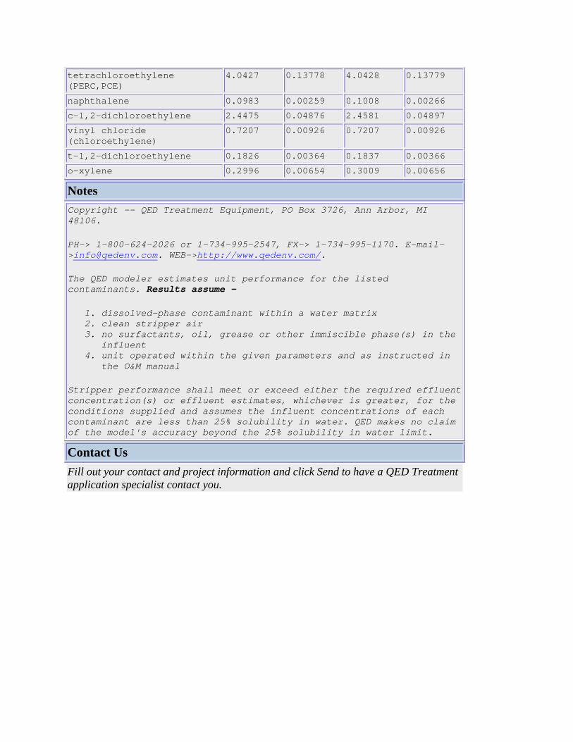
tetrachloroethylene (PERC,PCE)
4.0427 0.13778 4.0428 0.13779
naphthalene 0.0983 0.00259 0.1008 0.00266 c-1,2-dichloroethylene 2.4475 0.04876 2.4581 0.04897 vinyl chloride (chloroethylene)
0.7207 0.00926 0.7207 0.00926
t-1,2-dichloroethylene 0.1826 0.00364 0.1837 0.00366 o-xylene 0.2996 0.00654 0.3009 0.00656
Notes Copyright -- QED Treatment Equipment, PO Box 3726, Ann Arbor, MI 48106.
PH-> 1-800-624-2026 or 1-734-995-2547, FX-> 1-734-995-1170. E-mail->[email protected]. WEB->http://www.qedenv.com/.
The QED modeler estimates unit performance for the listed contaminants. Results assume -
1. dissolved-phase contaminant within a water matrix 2. clean stripper air 3. no surfactants, oil, grease or other immiscible phase(s) in the
influent 4. unit operated within the given parameters and as instructed in
the O&M manual
Stripper performance shall meet or exceed either the required effluent concentration(s) or effluent estimates, whichever is greater, for the conditions supplied and assumes the influent concentrations of each contaminant are less than 25% solubility in water. QED makes no claim of the model's accuracy beyond the 25% solubility in water limit.
Contact Us Fill out your contact and project information and click Send to have a QED Treatment application specialist contact you.