observer-based output-feedback control to eliminate ... · observer-based output-feedback control...
TRANSCRIPT

Observer-based output-feedback control to eliminate torsionaldrill-string vibrations
T.G.M. Vromen1, N. van de Wouw1, A. Doris2, P. Astrid3, H. Nijmeijer1
Abstract
Torsional stick-slip vibrations decrease the performance and reliability of drilling systems used for the exploration of energyand mineral resources. In this work, we present the design of a nonlinear observer-based output-feedback control strategy toeliminate these vibrations. We apply the controller to a drill-string model based on a real-life rig. Conditions, guaranteeingasymptotic stability of the desired equilibrium, corresponding to nominal drilling operation, are presented. The proposed controlstrategy has a significant advantage over existing vibration control systems in current drilling rigs as it only requires surfacemeasurements instead of expensive down-hole measurements and can handle multiple modes of torsional vibration. Case studyresults using the proposed control strategy show that stick-slip oscillations can indeed be eliminated in realistic drilling scenarios.
I. INTRODUCTION
Drilling systems are used to drill deep wells for the exploration and production of oil and gas, mineral resources andgeo-thermal energy. Fig. 1 shows a schematic drilling system. Surface and down-hole measurements [1], [2], [3] show thatthese systems experience different types of oscillations, which significantly decrease the drilling rate of penetration due todamage to the drill bit (e.g. bit tooth wear), drill pipes and bottom hole assembly (e.g. twisted pipe). Different modes ofvibration, such as axial, lateral and torsional vibrations, lead to bit bouncing, whirling and torsional stick-slip, respectively.The focus of the current paper is on the aspect of mitigation of torsional stick-slip oscillations by means of control as thesevibrations are known to be highly detrimental to drilling efficiency, reliability and safety.
For the design of controllers to eliminate torsional vibrations most studies rely on one- or two degree-of-freedom (DOF)models for the torsional drill-string dynamics only, see e.g. [4], [5], [6]. In these models, it is generally assumed that theresisting torque at the bit-rock interface can be modeled as a frictional contact with a velocity weakening effect as reportedin [7], [8]. In fact, modelling of the coupled axial and torsional dynamics, as for example in [9], shows that the velocityweakening effect in the torque-on-bit (TOB) is a consequence of the drilling dynamics, rather than an intrinsic property ofthe bit-rock interface. The fact that such coupling effectively leads to a velocity weakening effect of the TOB (see e.g. [10],[11]) motivates to adopt a modelling-for-control approach for drill-string dynamics involving the torsional dynamics only,as we will pursue in this paper.
This work is supported by Shell Global Solutions International.1 Eindhoven University of Technology, Department of Mechanical Engineering, 5600 MB Eindhoven, The Netherlands, {t.g.m.vromen,
n.v.d.wouw, h.nijmeijer}@tue.nl2 Well Engineering Design, Nederlandse Aardolie Maatschappij B.V. (NAM), The Netherlands, [email protected] Wells R&D, Shell Global Solutions International B.V., The Netherlands, [email protected]
Top drive
Rig
Bottom holeassembly
Bit
Drill pipe
Fig. 1. Schematic drilling system (adapted from [12]).

Different control strategies to suppress torsional vibrations can be found in literature. In [13], the use of torque feedback inaddition to a speed controller is investigated. The underlying idea is making the top rotary system behave in a “soft” manner,hence the name Soft Torque Rotary System, see also [5]. In these research contributions, it is assumed that the drilling systembehaves like a 2-DOF torsional pendulum of which the first torsional mode can be damped using a PI-controller based on thesurface angular velocity. In [8], [14], the above soft torque approach is compared with a control method based on torsionalrectification, which outperforms the soft torque approach in simulation studies by using improved torque feedback basedon the twist of the drill-string near the rotary. A linear H∞ controller synthesis approach is presented in [6]. Herein, thebit-rock interaction, key in causing stick-slip, is not taken into account in the controller design and stability analysis of theclosed-loop dynamics. A control design approach, where information of the nonlinear bit-rock interaction model is explicitlytaken into account in the controller synthesis, is proposed in [4], [15], [16]. Drawbacks of the approaches in [4], [6] are,firstly, the necessity of down-hole measurements reflecting the twist of the drill-string between surface and bit, which cannot be measured in practice, and, secondly, the fact that only one torsional mode of the drill-string is taken into account.
Increasing demands on the operating envelope and a tendency towards drilling deeper and inclined wells impose higherdemands on the controllers used in drilling systems. Industrial controllers are not always able to eliminate stick-slip vibrationsunder the imposed operating conditions. Two main reasons for this deficiency are the influence of multiple dynamical modesof the drill-string on torsional vibrations and the uncertainty in the bit-rock interaction law. The main contribution of this paperis an output-feedback control strategy mitigating torsional stick-slip vibrations while 1) only using surface measurements, 2)taking into account a multi-modal drill-string model and 3) taking into account severe velocity weakening and uncertaintyin the bit-rock interaction.
This paper is organized as follows. Section II introduces the drill-string model based on a finite element model of a real-liferig. Subsequently, in Section III we present the design of an output-feedback controller including a robust stability analysisof the resulting closed-loop system. Section IV will present simulation results illustrating the effectiveness of the proposedapproach while comparing the results with those obtained using an industrial controller. Finally, we draw conclusions inSection V.
Preliminaries: In support of the controller design result in Section III-A we present the following definitions on input-to-state-stability (ISS) and the strict passivity property.
The concept of input-to-state stability has been introduced in [17]. Its local version has first appeared in [18].Definition 1: The system x(t) ∈ F (x(t), e(t)) is locally input-to-state stable (LISS) if there exist constants c1, c2 > 0, a
function ρ of class KL and a function µ of class K such that for each initial condition x(0) = x0, such that ‖x0‖ ≤ c1, andeach piecewise continuous bounded input function e(t) defined on [0,∞) and satisfying supτ∈[0,∞) ‖e(τ)‖ ≤ c2, it holdsthat• all solutions x(t) exist on [0,∞) and,• all solutions satisfy
‖x(t)‖ ≤ ρ (‖x0‖ , t) + µ
(supτ∈[0,t]
‖e(τ)‖), ∀t ≥ 0. (1)
Consider the linear time-invariant minimal realizationx = Ax+Gwz = Hx+Dw
(2)
with the state x ∈ Rn, input and output w, z ∈ R.Definition 2: The system (2) or the quadruple (A,G,H,D) is said to be strictly passive if there exist an ε > 0 and a
matrix P = P> > 0 such that [A>P + PA+ εI PG−H>
G>P −H −D −D>]≤ 0. (3)
II. DRILL-STRING MODELThe system we will investigate is a realistic drill-string model of a jack-up drilling rig and the reservoir sections of the
wells are drilled with a 6” bit to reach depths of >6000 m and with an inclination angle up to 60◦, resulting in significantresistive torques along the drill-string. The rig is equipped with an AC top drive and fitted with a modern Soft Torque system[19]. However, for this depth and hole size stick-slip vibrations have been observed in the field for this rig. A finite elementmodel of this drilling system has been developed and the simulation results of this model have been validated with fielddata under different conditions (such as weight-on-bit (WOB) and angular velocity).
The finite element method (FEM) representation of the drill-string is a model with 18 elements. The element at the top is arotational inertia to model the top drive inertia, the following elements are equivalent pipe sections based on the dimensionsand material properties of the drill-string. The resulting model can be written as
Mq +Dq +Ktqd = SwTw(q) + SbTbit(q1) + SmTm (4)

ii
“FRF˙torque˙input˙sur˙velocity˙output˙bit˙temp” — 2014/3/20 — 20:51 — page 1 — #1 ii
ii
ii
10−2
10−1
100
101
10−20
10−10
100
Magn
itude[rad
/Nm
s]
18 DOF modelReduced−order model
10−2
10−1
100
101
−3000
−2000
−1000
0
Phase[deg]
Frequency [Hz]
Fig. 2. Frequency response function of the full-order and reduced-order model from input torqueTm to bit velocity ωbit.
ii
“FRF˙torque˙input˙bit˙velocity˙output˙bit˙temp” — 2014/3/20 — 20:51 — page 1 — #1 ii
ii
ii
10−2
10−1
100
101
10−10
10−5
100
Mag
nitude[rad
/Nm
s]
18 DOF modelReduced−order model
10−2
10−1
100
101
−100
0
100
200
300
Phase[deg]
Frequency [Hz]
Fig. 3. Frequency response function of the full-order and reduced-order model from bit torqueTbit to bit velocity ωbit, i.e. bit mobility.
ii
“FRF˙torque˙input˙sur˙velocity˙output˙sur˙temp” — 2014/3/20 — 20:51 — page 1 — #1 ii
ii
ii
10−2
10−1
100
101
10−6
10−4
10−2
100
Mag
nitude[rad
/Nm
s]
18 DOF modelReduced−order model
10−2
10−1
100
101
−100
−50
0
50
100
Phase[deg]
Frequency [Hz]
Fig. 4. Frequency response function of the full-order and reduced-order model from input torqueTm to top drive velocity ωtd.
with the coordinates q ∈ Rn with n = 18, the top drive motor torque input Tm ∈ R being the control input, the bit-rock inter-action torque Tbit ∈ R and the interaction torques Tw ∈ Rn−1 between the borehole and the drill-string acting on the nodes ofthe FEM model. The coordinates q represent the angular displacements of the nodes of the finite element representation. Next,we define the difference in angular position between adjacent nodes as follows; qd :=
[q1 − q2 q2 − q3 · · · q17 − q18
]>.
In (4), the mass, damping and stiffness matrices are, respectively, given by M ∈ Rn×n, D ∈ Rn×n and Kt ∈ Rn×n−1, thematrices Sw ∈ Rn×n−1, Sb ∈ Rn×1 and Sm ∈ Rn×1 represent the generalized force directions of the input torque, the bittorque and the interaction torques, respectively. The coordinates q are chosen such that the first element (q1) describes therotation of the bit and the last element (q18) the rotation of the top drive at surface. The interaction between the boreholeand the drill-string is modeled as Coulomb friction, that is
Tw,i ∈ Ti Sign (qi) , for i = 2, . . . , 18, (5)
with Ti representing the amount of friction at each element and the set-valued sign function defined as
Sign (y) ,
−1, y < 0[−1, 1] , y = 01, y > 0.
(6)
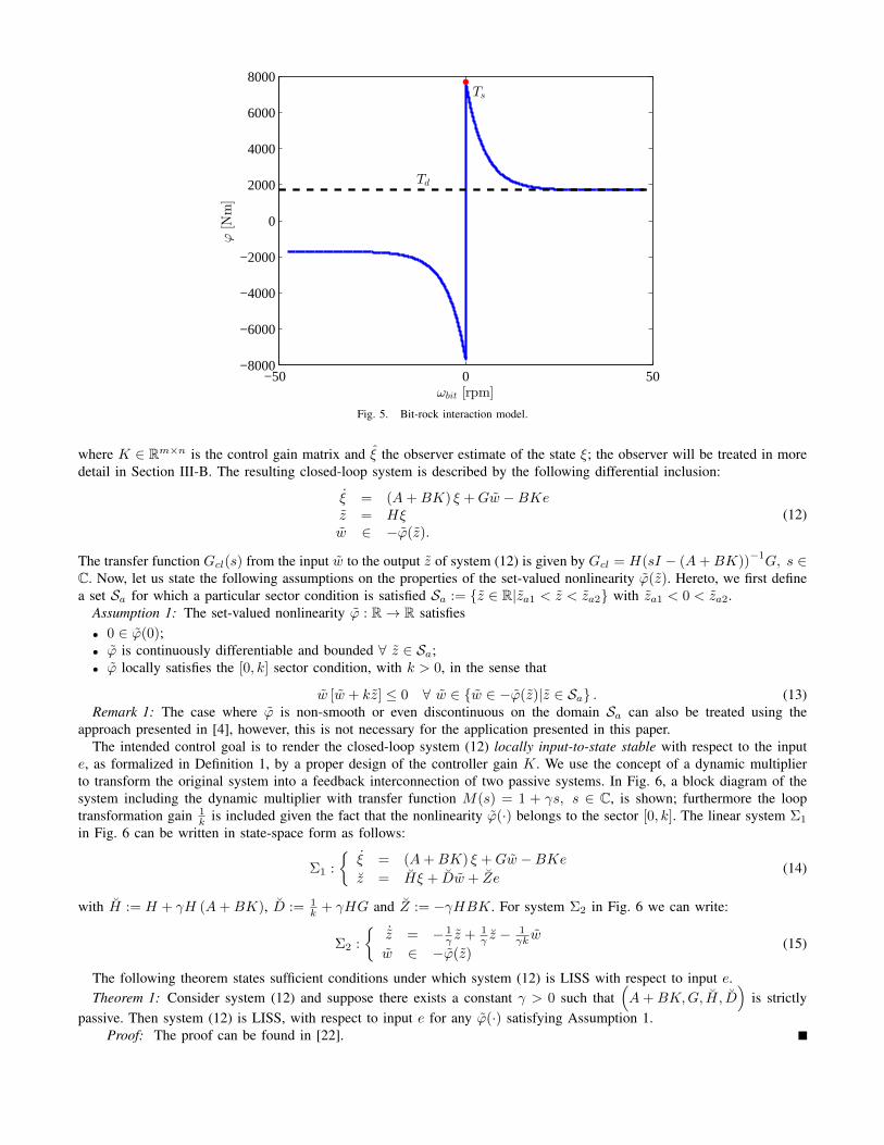
The bit-rock interaction model is given by
Tbit(q1) = Sign (q1)(Td + (Ts − Td) e−vd|q1|
)(7)
with Ts the static torque, Td the dynamic torque and vd; = 30Ndπ
indicating the decrease from static to dynamic torque. Themodel (4), (5) and (7) together forms a differential inclusion that we can write in state-space Lur’e-type form as:
˙x = Ax+ Gw + G2w2 + Buz = Hxz2 = H2xy = Cxw ∈ −ϕ(z)w2 ∈ −φ(z2),
(8)
where x :=[q>d q>
]> ∈ R2n−1 is the state, z := ωbit ∈ R and z2 := [q2, . . . , q18]> ∈ Rn−1 are the angular velocity
arguments of the set-valued nonlinearities ϕ and φ, respectively. The bit-rock interaction torque is given by w ∈ R and thedrill-string-borehole interaction torques are given by w2 ∈ Rn−1, u := Tm ∈ R is the control input and y :=
[ωtd Tpipe
]> ∈R2 is the measured output. Note that the latter implies that only surface measurements will be employed in the output-feedback control strategy proposed in Section III. The angular velocities of the top drive and the bit are defined as ωtd := q18
and ωbit := q1, respectively, and the pipe torque Tpipe is the torque in the drill-string directly below the top drive. Thematrices A, B, G, G2, H and H2 in (8), with appropriate dimensions are given by
A =
[017×17 a−M−1Kt −M−1D
], a =
1 −1 0 · · · 0
0. . .
. . .. . .
......
. . .. . .
. . . 00 · · · 0 1 −1
B =
[017×1
M−1Sm
], G =
[017×1
M−1Sb
], G2 =
[017×17
M−1Sw
],
H =[01×17 1 01×17
], H2 =
[017×18 I17
],

and C ∈ R2×2n−1 indicates the measured output. Note that ϕ(z) := Tbit(z) and φ(z2) := [Tw,2(q2), . . . , Tw,18(q18)]>.
A. Reduced-order model
To facilitate the design and to decrease the implementation burden of observer-based output-feedback controllers (seeSection III), we apply model reduction to obtain a low-order approximation of the drilling system dynamics (8), thatapproximates the input-output behavior from inputs u and w to outputs y and z. The inputs and outputs related to thedrill-string-borehole interaction (Tw,i) are not taken into account in the reduction process, but can be approximated using thetransformation matrix obtained from the reduction procedure. With this assumption, system (8) can be represented as a Lur’etype system Σ =
(Σlin, ϕ
), consisting of high-order linear dynamics Σlin with a single static output-dependent nonlinearity
ϕ, related to the bit-rock interaction, in the feedback loop. We will use the model reduction approach for Lur’e-type systemsas proposed in [20], which employs a linear model reduction technique (such as balanced truncation) for the reduction ofthe linear part of the Lur’e-type system. In doing so, we combine the inputs u and w and the outputs y and z, yielding thenew input matrix
[B G
]and the new output matrix
[C> H>
]>. By applying balanced truncation to the linear part of
the Lur’e-type system we obtain the reduced-order linear system Σlin. Now, the reduced-order linear part is interconnectedwith the original nonlinearity yielding the reduced-order drill-string system Σ = (Σlin, ϕ).
Using the approach outlined above, we obtain a reduced-order model with state x ∈ Rn, with n = 7. The equations ofmotion for the reduced-order system are written as
x = Ax+Gw +G2w2 +Buz = Hxz2 = H2xy = Cxw ∈ −ϕ(z)w2 ∈ −φ(z2),
(9)
and an experimentally validated bit-rock interaction model is shown in Fig. 5. The relevant frequency response functionsfor the linear part of the dynamics in (9) are shown in Figs. 2, 3 and 4. Clearly, the first three resonance modes (and therigid-body mode) are accurately captured in the reduced-order model. The so-called bit mobility, shown in Fig. 3, gives anindication of the important resonance modes in the onset of stick-slip vibrations. It can be seen that the first three resonancemodes are dominant, which motivates the choice to reduce to a model order of n = 7.
III. DESIGN OF AN OUTPUT-FEEDBACK CONTROLLER
We employ an observer-based controller synthesis strategy for Lur’e-type systems with discontinuities as in [4], [21].In these previous works the controller and observer were designed for a drill-string model with a single flexibility modeand with the assumption on the availability of down-hole measurements. The conditions for controller synthesis as in [4]achieving global asymptotic stability are infeasible for the realistic drill-string model presented here for three reasons: firstly,the incorporation of more realistic drill-string dynamics including multiple torsional flexibility modes of the drill-string, seeFigs. 2, 3 and 4, secondly, the incorporation of a bit-rock interaction model based on field data, which shows a rathersevere velocity weakening effect, see Fig. 5 and, thirdly, the restriction on the availability of only surface measurements.Therefore, we employ a controller synthesis strategy to design locally stabilizing controllers and we show that such localstability properties suffice in realistic drilling scenarios. In Section III-A, we will propose the state-feedback controller, inSection III-B, the observer design and in Section III-C, the resulting output-feedback control strategy, all including stabilityguarantees.
A. State-feedback controller
In this section, we discuss the design of a state-feedback controller for systems in the form
ξ = Aξ +Bufb +Gwz = Hξw ∈ −ϕ(z)
(10)
that stabilizes the origin ξ = 0 of the system state ξ ∈ Rn. Stabilization of the origin of (10) corresponds to the desiredoperation of constant angular velocity of the drilling system. The relation between systems (9) and (10) will be explained inmore detail in Section IV, while this section focusses on the design of controllers for generic systems of the form (10). Thecontrol input is given by ufb ∈ Rm, the input and output of the set-valued nonlinearity ϕ are given by z ∈ R and w ∈ R,respectively, and the system matrices are A ∈ Rn×n, B ∈ Rn×m, G ∈ Rn×1 and H ∈ R1×n. We introduce the linear staticstate-feedback law, where we take the “measurement” (or observer) error e := ξ − ξ into account:
ufb = Kξ = K (ξ − e) , (11)
ii
“phi˙matlab˙temp” — 2014/3/20 — 20:52 — page 1 — #1 ii
ii
ii
−50 0 50−8000
−6000
−4000
−2000
0
2000
4000
6000
8000
ωbit [rpm]
ϕ[Nm]
Ts
Td
Fig. 5. Bit-rock interaction model.
where K ∈ Rm×n is the control gain matrix and ξ the observer estimate of the state ξ; the observer will be treated in moredetail in Section III-B. The resulting closed-loop system is described by the following differential inclusion:
ξ = (A+BK) ξ +Gw −BKez = Hξw ∈ −ϕ(z).
(12)
The transfer function Gcl(s) from the input w to the output z of system (12) is given by Gcl = H(sI − (A+BK))−1G, s ∈
C. Now, let us state the following assumptions on the properties of the set-valued nonlinearity ϕ(z). Hereto, we first definea set Sa for which a particular sector condition is satisfied Sa := {z ∈ R|za1 < z < za2} with za1 < 0 < za2.
Assumption 1: The set-valued nonlinearity ϕ : R→ R satisfies• 0 ∈ ϕ(0);• ϕ is continuously differentiable and bounded ∀ z ∈ Sa;• ϕ locally satisfies the [0, k] sector condition, with k > 0, in the sense that
w [w + kz] ≤ 0 ∀ w ∈ {w ∈ −ϕ(z)|z ∈ Sa} . (13)Remark 1: The case where ϕ is non-smooth or even discontinuous on the domain Sa can also be treated using the
approach presented in [4], however, this is not necessary for the application presented in this paper.The intended control goal is to render the closed-loop system (12) locally input-to-state stable with respect to the input
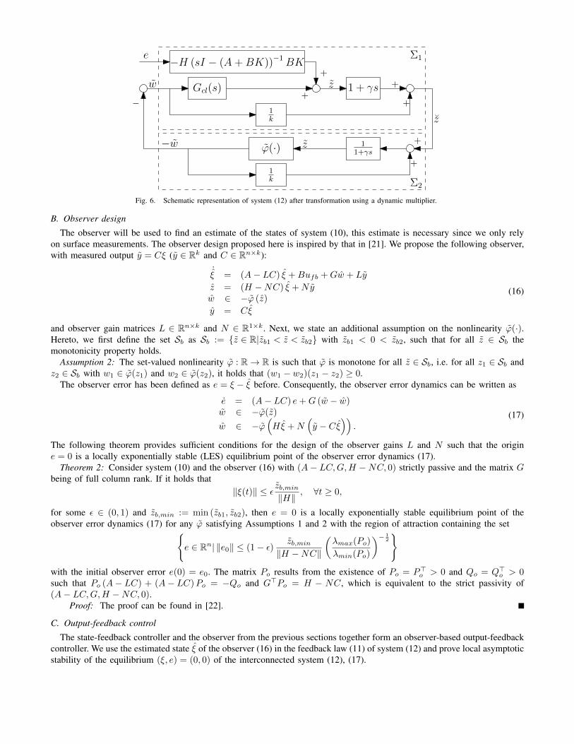
e, as formalized in Definition 1, by a proper design of the controller gain K. We use the concept of a dynamic multiplierto transform the original system into a feedback interconnection of two passive systems. In Fig. 6, a block diagram of thesystem including the dynamic multiplier with transfer function M(s) = 1 + γs, s ∈ C, is shown; furthermore the looptransformation gain 1
k is included given the fact that the nonlinearity ϕ(·) belongs to the sector [0, k]. The linear system Σ1
in Fig. 6 can be written in state-space form as follows:
Σ1 :
{ξ = (A+BK) ξ +Gw −BKez = Hξ + Dw + Ze
(14)
with H := H + γH (A+BK), D := 1k + γHG and Z := −γHBK. For system Σ2 in Fig. 6 we can write:
Σ2 :
{˙z = − 1
γ z + 1γ z − 1
γk w
w ∈ −ϕ(z)(15)
The following theorem states sufficient conditions under which system (12) is LISS with respect to input e.Theorem 1: Consider system (12) and suppose there exists a constant γ > 0 such that
(A+BK,G, H, D
)is strictly
passive. Then system (12) is LISS, with respect to input e for any ϕ(·) satisfying Assumption 1.Proof: The proof can be found in [22].
Gcl(s) z 1 + γs +
+
ϕ(·) 11+γs
+
+
−
w
−w
z
z
1k
1k
e Σ1
Σ2
+
−H (sI − (A+BK))−1BK+
Fig. 6. Schematic representation of system (12) after transformation using a dynamic multiplier.
B. Observer design
The observer will be used to find an estimate of the states of system (10), this estimate is necessary since we only relyon surface measurements. The observer design proposed here is inspired by that in [21]. We propose the following observer,with measured output y = Cξ (y ∈ Rk and C ∈ Rn×k):
˙ξ = (A− LC) ξ +Bufb +Gw + Ly
z = (H −NC) ξ +Nyw ∈ −ϕ (z)
y = Cξ
(16)
and observer gain matrices L ∈ Rn×k and N ∈ R1×k. Next, we state an additional assumption on the nonlinearity ϕ(·).Hereto, we first define the set Sb as Sb := {z ∈ R|zb1 < z < zb2} with zb1 < 0 < zb2, such that for all z ∈ Sb themonotonicity property holds.
Assumption 2: The set-valued nonlinearity ϕ : R→ R is such that ϕ is monotone for all z ∈ Sb, i.e. for all z1 ∈ Sb andz2 ∈ Sb with w1 ∈ ϕ(z1) and w2 ∈ ϕ(z2), it holds that (w1 − w2)(z1 − z2) ≥ 0.
The observer error has been defined as e = ξ − ξ before. Consequently, the observer error dynamics can be written as
e = (A− LC) e+G (w − w)w ∈ −ϕ(z)
w ∈ −ϕ(Hξ +N
(y − Cξ
)).
(17)
The following theorem provides sufficient conditions for the design of the observer gains L and N such that the origine = 0 is a locally exponentially stable (LES) equilibrium point of the observer error dynamics (17).
Theorem 2: Consider system (10) and the observer (16) with (A− LC,G,H −NC, 0) strictly passive and the matrix Gbeing of full column rank. If it holds that
‖ξ(t)‖ ≤ ε zb,min‖H‖ , ∀t ≥ 0,
for some ε ∈ (0, 1) and zb,min := min (zb1, zb2), then e = 0 is a locally exponentially stable equilibrium point of theobserver error dynamics (17) for any ϕ satisfying Assumptions 1 and 2 with the region of attraction containing the set{
e ∈ Rn| ‖e0‖ ≤ (1− ε) zb,min‖H −NC‖
(λmax(Po)
λmin(Po)
)− 12
}with the initial observer error e(0) = e0. The matrix Po results from the existence of Po = P>o > 0 and Qo = Q>o > 0such that Po (A− LC) + (A− LC)Po = −Qo and G>Po = H − NC, which is equivalent to the strict passivity of(A− LC,G,H −NC, 0).
Proof: The proof can be found in [22].
C. Output-feedback control
The state-feedback controller and the observer from the previous sections together form an observer-based output-feedbackcontroller. We use the estimated state ξ of the observer (16) in the feedback law (11) of system (12) and prove local asymptoticstability of the equilibrium (ξ, e) = (0, 0) of the interconnected system (12), (17).

ii
“phi˙tilde˙matlab˙with˙zoom˙in˙temp” — 2014/3/20 — 20:52 — page 1 — #1 ii
ii
ii
z [rpm]
ϕ[N
m]
za1 zb1
kz
−150 −100 −50 0 50−10000
−8000
−6000
−4000
−2000
0
2000
4000
6000
za1 zb1
−40 −20 0 20−100
0
100
Fig. 7. Transformed bit-rock interaction model ϕ(z).
Theorem 3: Consider system (12) and observer (16). Suppose the conditions in Theorem 1 are satisfied for system (12) andthat the observer error dynamics in (17) satisfies the conditions in Theorem 2. Then, (ξ, e) = (0, 0) is a locally asymptoticallystable equilibrium point of the interconnected system (12), (17) for any ϕ satisfying Assumptions 1 and 2.
Proof: The proof can be found in [22].
IV. SIMULATION RESULTS
In this section, we will show the application of the observer-based output-feedback controller (see Section III) to thereduced-order drill-string model presented in Section II. To stabilize the desired equilibrium xeq of system (9) we have todesign the controller gain K and the observer gains L and N to apply the control torque
u = uff +Kξ, (18)
with uff a constant feedforward torque to obtain the equilibrium (desired constant positive rotational velocity) and Kξ thefeedback torque based on the observer estimate ξ. If we assume that we can indeed operate the drill-string system at positiveangular velocity, the Coulomb friction terms Tw,i along the drill-string do not affect the dynamics of the system, at leastlocally near the desired operating condition, and can consequently be represented by constant resistive torques. These constantresistive torques, can then be compensated by the feedforward torque. The equilibrium xeq and feedforward torque uff canbe obtained from the equilibrium condition of system (9) that has to satisfy Axeq−Gϕ (Hxeq)−G2φ (H2xeq)+Buff = 0and we require that y1 = ωtd matches the desired equilibrium velocity ωeq .
Now, we have to write the system (9) in the form (10) and such that the set-valued nonlinearity satisfies the conditionsin Assumptions 1 and 2. Therefore, we write the reduced-order drill-string system in perturbation states, i.e. ξ := x− xeq .Furthermore, we apply a linear loop transformation to change the properties of the nonlinearity ϕ. This results in thefollowing state-space representation
ξ = Atξ +Bufb +Gwz = Hξw ∈ −ϕ (z)
(19)
with δ > 0 a constant to apply the linear loop transformation, ϕ (z) := ϕ (z +Hxeq)−ϕ (Hxeq)+δz and w = w−weq−δzand we define At := A+ δGH . The transformed nonlinearity ϕ (z) is shown in Fig. 7. As can be seen in this figure, ϕ (z)belongs locally to the sector [0, k] with k = 570 Nms/rad (note δ = 29.2 Nms/rad in this case). The physical meaning ofthis condition is that the amount of velocity weakening in the bit-rock interaction is limited. A larger sector, including thetotal nonlinearity ϕ (z), would result in high control gains K. Such high gains result in high control torques u that can notbe realized by the top drive and are therefore infeasible in practice. In Fig. 7, we have also indicated the point za1 = −28.9rpm for which holds that for za1 < z < za2 the sector condition is satisfied (i.e. za2 can be chosen arbitrarily large inthis case) and the point zb1 = −20.1 rpm such that for zb1 < z < zb2 it holds that ϕ is monotonically increasing (i.e.zb2 can also be chosen arbitrarily large in this case), as stated in Assumption 1 and 2, respectively. The last condition inAssumption 1 states that the bit-rock interaction model is bounded by a linear function.

ii
“sim˙result˙STRS˙temp” — 2014/3/20 — 20:52 — page 1 — #1 ii
ii
ii
0 10 20 30 40 50 60 70 800
20
40
60
80
Top
drive
angularvelocity
[rpm]
0 10 20 30 40 50 60 70 80−100
0
100
200
300
400
Time [s]
Bitan
gularvelocity
[rpm]
ωtd
ωref
ωeq
Fig. 8. Simulation result of the reduced-order model with an existing industrial controller.
The controller and observer gains are designed according to the conditions given in Theorem 1 and Theorem 2, respectively.The results are obtained by using SeDuMi 1.3 [23], a linear matrix inequality (LMI) solver and the YALMIP interface [24].Hence, the controller gains K are determined by finding a solution such that (At +BK,G, H, D) is strictly passive, withH and D as defined in (14). To find the observer gains L and N we have to satisfy the strict passivity conditions for(At − LC,G,H −NC, 0).
Before we show the simulation results of the designed output-feedback controller, we will show a simulation result of thereduced-order drill-string system in closed-loop with an existing industrial controller (based on [5]). For the simulations, weintroduce a so-called startup scenario, which is based on practical startup procedures for drilling rigs. Herein, the drill-stringis first accelerated to a low constant rotational velocity with the bit above the formation (off bottom) and, subsequently, theangular velocity and weight-on-bit (WOB) are gradually increased to the desired operating conditions. The startup scenariois built up as follows:
1) Start with WOB = 0, such that there is no velocity weakening effect in the bit-rock interaction model and use theindustrial PI-controller to operate at relatively low velocity and build up torque in drill-string to overcome static torquesdue to drag in the time window 0 < t < 20 s;
2) Turn on the controller (18) and slowly increase the reference angular velocity until the desired operating velocity (ωeq)is reached (in the time window 20 ≤ t < 40 s). At the same time, slowly increase the WOB to let the bit bite theformation and finally obtain the nominal operating condition in the angular velocity and WOB.
A simulation result of the reduced-order model with the industrial controller is shown in Fig. 8. The controller is a properlytuned active damping system (i.e. PI-control of the angular velocity) which aims at damping the first torsional mode of thedrill-string dynamics. In the upper plot the top drive velocity (ωtd) is shown along with the reference velocity ωref thatstarts at a velocity of approximately 20 rpm and is gradually increased to the desired equilibrium velocity, ωeq , of 50 rpm.From the bit response, in the bottom plot, we can clearly recognize stick-slip oscillations. The increasing amplitude of theoscillations in the top drive velocity, demonstrates that these vibrations arise when the WOB is increased (20 ≤ t < 40 s).
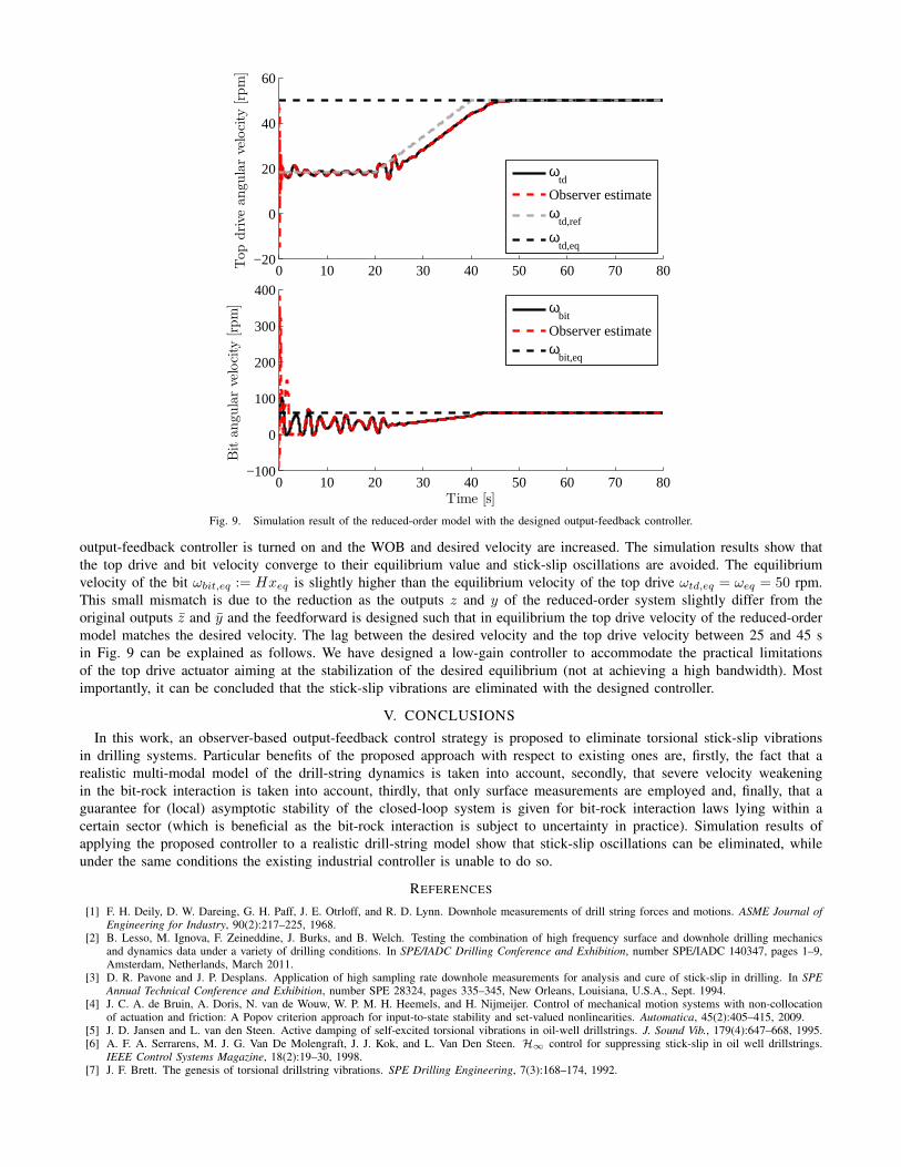
For the designed output-feedback controller, we immediately activate (at t = 0) the observer to obtain the state estimateξ; however, this estimate is not used by the industrial PI-controller in the first 20 seconds (since this controller only usesthe top drive velocity as a measured output). When the state-feedback controller is switched on at t = 20, it uses the stateestimate ξ, based on the surface measurements ωtd and Tpipe only. Fig. 9 shows a simulation result of the closed-loopsystem with output-feedback controller, where we used the same initial conditions ξ0 as for the previous simulation (Fig. 8).Furthermore, the initial states for the observer ξ0 have a 10% offset from the initial states ξ0. It can be seen that after sometransient behavior, the observer estimates converge to the actual states within approximately 5 seconds. After 20 seconds the
ii
“sim˙result˙state˙feedback˙temp” — 2014/3/20 — 20:52 — page 1 — #1 ii
ii
ii
0 10 20 30 40 50 60 70 80−20
0
20
40
60
Top
drive
angu
larvelocity
[rpm]
ωtd
Observer estimateω
td,ref
ωtd,eq
0 10 20 30 40 50 60 70 80−100
0
100
200
300
400
Time [s]
Bitangu
larvelocity
[rpm]
ωbit
Observer estimateω
bit,eq
Fig. 9. Simulation result of the reduced-order model with the designed output-feedback controller.
output-feedback controller is turned on and the WOB and desired velocity are increased. The simulation results show thatthe top drive and bit velocity converge to their equilibrium value and stick-slip oscillations are avoided. The equilibriumvelocity of the bit ωbit,eq := Hxeq is slightly higher than the equilibrium velocity of the top drive ωtd,eq = ωeq = 50 rpm.This small mismatch is due to the reduction as the outputs z and y of the reduced-order system slightly differ from theoriginal outputs z and y and the feedforward is designed such that in equilibrium the top drive velocity of the reduced-ordermodel matches the desired velocity. The lag between the desired velocity and the top drive velocity between 25 and 45 sin Fig. 9 can be explained as follows. We have designed a low-gain controller to accommodate the practical limitationsof the top drive actuator aiming at the stabilization of the desired equilibrium (not at achieving a high bandwidth). Mostimportantly, it can be concluded that the stick-slip vibrations are eliminated with the designed controller.
V. CONCLUSIONS
In this work, an observer-based output-feedback control strategy is proposed to eliminate torsional stick-slip vibrationsin drilling systems. Particular benefits of the proposed approach with respect to existing ones are, firstly, the fact that arealistic multi-modal model of the drill-string dynamics is taken into account, secondly, that severe velocity weakeningin the bit-rock interaction is taken into account, thirdly, that only surface measurements are employed and, finally, that aguarantee for (local) asymptotic stability of the closed-loop system is given for bit-rock interaction laws lying within acertain sector (which is beneficial as the bit-rock interaction is subject to uncertainty in practice). Simulation results ofapplying the proposed controller to a realistic drill-string model show that stick-slip oscillations can be eliminated, whileunder the same conditions the existing industrial controller is unable to do so.
REFERENCES
[1] F. H. Deily, D. W. Dareing, G. H. Paff, J. E. Otrloff, and R. D. Lynn. Downhole measurements of drill string forces and motions. ASME Journal ofEngineering for Industry, 90(2):217–225, 1968.
[2] B. Lesso, M. Ignova, F. Zeineddine, J. Burks, and B. Welch. Testing the combination of high frequency surface and downhole drilling mechanicsand dynamics data under a variety of drilling conditions. In SPE/IADC Drilling Conference and Exhibition, number SPE/IADC 140347, pages 1–9,Amsterdam, Netherlands, March 2011.
[3] D. R. Pavone and J. P. Desplans. Application of high sampling rate downhole measurements for analysis and cure of stick-slip in drilling. In SPEAnnual Technical Conference and Exhibition, number SPE 28324, pages 335–345, New Orleans, Louisiana, U.S.A., Sept. 1994.
[4] J. C. A. de Bruin, A. Doris, N. van de Wouw, W. P. M. H. Heemels, and H. Nijmeijer. Control of mechanical motion systems with non-collocationof actuation and friction: A Popov criterion approach for input-to-state stability and set-valued nonlinearities. Automatica, 45(2):405–415, 2009.
[5] J. D. Jansen and L. van den Steen. Active damping of self-excited torsional vibrations in oil-well drillstrings. J. Sound Vib., 179(4):647–668, 1995.[6] A. F. A. Serrarens, M. J. G. Van De Molengraft, J. J. Kok, and L. Van Den Steen. H∞ control for suppressing stick-slip in oil well drillstrings.
IEEE Control Systems Magazine, 18(2):19–30, 1998.[7] J. F. Brett. The genesis of torsional drillstring vibrations. SPE Drilling Engineering, 7(3):168–174, 1992.

[8] R. W. Tucker and C. Wang. On the effective control of torsional vibrations in drilling systems. J. Sound Vib., 224(1):101–122, 1999.[9] T. Richard, C. Germay, and E. Detournay. A simplified model to explore the root cause of stick-slip vibrations in drilling systems with drag bits. J.
Sound Vib., 305(3):432–456, 2007.[10] B. Besselink, N. van de Wouw, and H. Nijmeijer. A semi-analytical study of stick-slip oscillations in drilling systems. Journal of Computational
and Nonlinear Dynamics, 6(2):021006–1 to 021006–9, 2011.[11] C. Germay, N. van de Wouw, R. Sepulchre, and H. Nijmeijer. Nonlinear drillstring dynamics analysis. SIAM Journal on Applied Dynamical Systems,
8(2):527553, 2009.[12] L. Perneder and E. Detournay. Steady-state solutions of a propagating borehole. Int. Journal of Solids and Structures, 50:1226 – 1240, 2013.[13] G. W. Halsey, A. Kyllingstad, and A. Kylling. Torque feedback used to cure slip-stick motion. In SPE Annual Technical Conference and Exhibition,
number SPE 18049, pages 277–282, Houston, Texas, U.S.A., October 1988.[14] R.W. Tucker and C. Wang. Torsional vibration control and cosserat dynamics of a drill-rig assembly. Meccanica, 38(1):143–159, 2003.[15] A. Doris. Controlling vibrations in a drilling system. Patent, WO 2012/084886 A1, 2012.[16] A. Doris. Method and system for controlling vibrations in a drilling system. Patent, WO 2013/076184 A2, 2013.[17] E.D. Sontag and Y. Wang. On characterizations of the input-to-state stability property. Systems and Control Letters, 24(5):351–259, 1995.[18] E.D. Sontag and Y. Wang. New characterizations of input-to-state stability. IEEE Trans. on Automatic Control, 41(9):1283–1294, 1996.[19] A. Kyllingstad and P. J. Nessjøen. A new stick-slip prevention system. In SPE/IADC Drilling Conference and Exhibition, number SPE/IADC 199660,
Amsterdam, Netherlands, March 2009.[20] B. Besselink, N. van de Wouw, and H. Nijmeijer. Model reduction for nonlinear systems with incremental gain or passivity properties. Automatica,
49(4):861 – 872, 2013.[21] A. Doris, A. L. Juloski, N. Mihajlovic, W. P. M. H. Heemels, N. van de Wouw, and H. Nijmeijer. Observer designs for experimental non-smooth
and discontinuous systems. IEEE Trans. on Control Systems Technology, 16(6):1323–1332, 2008.[22] T.G.M. Vromen, N. van de Wouw, A. Doris, P. Astrid, and H. Nijmeijer. DC2014.045: Observer-based output-feedback control to eliminate torsional
drill-string vibrations. Technical report, Eindhoven University of Technology, 2014.[23] J. F. Sturm. Using sedumi 1.02, a matlab toolbox for optimization over symmetric cones. Optimization Methods and Software, 11(1-4):625–653,
1999.[24] J. Lofberg. YALMIP : A toolbox for modeling and optimization in MATLAB. In CCA/ISIC/CACSD, September 2004.