o'brien & gere - attachments a & b of supplemental … · feasibility study...
TRANSCRIPT

\
/ i . ' • • • ^ - '
OSniENGGERlH
-ebruary 28, 1989
*.-
EPA Region 5 Records Ctr I \
387355
V f ' c -'t "j
1
('tfo 0^0
n^s-h
Ms. M.P. Logan Remed i.a 1 P r o j e c t Manag'cr U..S. E.'n'fRONMb.NTAI, PRUTI.C^ 1 U.
" AGENCY, REGION \^ 250 Sot-ith Dea rbo rn S t r e e t C h i c a g o , l l l i n o i ' S bUbO-l
Rc: l i rab Orcha rd .Nat iona l U'l 1 d 1 I t"e Refuge
hi Ic : .il'l 4 .DO] - -
-9
"Dear .Ms.' l .ogjn:
Hncloscd_ pleascj . fini-1 .-\i t achmcnt s ,-\ ,irid B which J e s c r i h j su-jpl ci.'ien tH 1 .. s i t c ' ^ c h a r a c t e r i z a t i o n a'"'nd t rca t a b i 1 i t.\- t e s t i n g lecomiM'ndoa b.v O ' B r i e n <;
1) Gere I n i g i n e t r s - , I n c . f o r t h e Crah Orchard .Nat ipnal hi Id l i f e Refuge F e a s i b i l i t y Stud.v a.s m o d i f i e d h \ t h e U . S . l-ish (, I v i l d F i f e . S e r v i c e . These dacumcnf-^ a r e t"orv%.irded foi- i n c l u s i o n in the .\ilrm n i s t ra 11 v e R e c o r d .
P1 e a s e - c o n t a c t ine it' > cm h a u ; an>- q u e s t i c m s or c o n m e h t s .
• Very t r u l y \-ours, ' ' ^
0'BRIE,N S ULRl: L.\G i .ShI.RS,. I \ L . " ', . -
• j .
s
f l <
SteVen R. Garv-cr , V 1 5 e , P r e s i d e n t
,,^ MSB/^ii'd:n 11 : 13. Ericlb^i i ' res ' .
y i . : • • • ] - y
•
P.I-.
( 1
)'
i% :i,A.' X iy4M!&iy M . i-^-^f.^i•-•

^ ^ ^ S 0 A A t : ' ¥:,. t.--•••' •"' :. '^'^'''A'^^M tmmmmyy y '-"y--- • • - • r y y ^^imw^^^yi^yy^y: ' 'y - -• '•
K?S:-, ' f .V; ' . . ' ; ' : r i- ' i ' ' -- j . .r ,-- ' - • -'• ;.'.'•,'." .,• ••''
;,-. t ; ? , ; . • - - - • * - :- ,••- - S ' ' - -- - " " ! . .1 t-
I miAyWi > - / K ^ . •
v"!.#^l
«. < I ATTACHMENTS
- «•• . -
.»n
= f 4s4'
:-. ' . !-.v - • , *
' ' '. - t .
- ' - - • j ; v
y y y m ' £ • 1 " < . ' ' * - r i - , - ; ' ^ - -

&%A': 'y
¥'-y-\
^ iyy0M{ i^ • y i y y r y . \ ! .
'.-'' - i
p ??''-';^|-'K?St^?^?';4'lp-Vpff!|jS^
•• ^•^ '•- \ --^:yyy§:-s!y^A •:• '. y y - ^ ^ r A m ^
i . ' • • • ' - : - > ' : . : s : v ; ; ; r 4 " i ; > ; ' ^ V^il^iai;;!.
S
^ * ' ' ./ ATTACHMENTA ;
SUPPLEMENTAL ^ITE CHARACTERIZATION PROPOSAL,
-J"
• *
^
* -
5,=?*.
'^
•• " J "
P..
' / i ' •

m^^^A^^y ' iy0P- ' ' ' " - ' y '•'•'• • ' ' - ' - " • • • • -- " •
m i 9 i 0 M A A ' ^ - A ' •" • ' • • - ' • • ' • '• ,•
.^v-^tfi' 'V^^iS?;-*'?^;;^';?
'y": A''\A:'^A&^ilM$
?
>
s'-lj^;;-?;
mixs-yyi.-:.-
i
. XTTACHMENTA I » , , - , , • - •
^ SUPPLEMENTAL SITE CHARACTERIZATION P R 5 P 0 S A | L
Crab Orchard National WUdlife Refuge feasibility Study
• • . ' - ^
. • ^ . ' " • , ' • ' ' • . '
. Development of topographic surveys and collection and teeing ,of suppkmeptaj sediment/soil samites are recommended to better define seven sites for their evaluation in the Feasibility Study. -The proposed field efforts for supplemental site characterization are dest^ribed herein.
Topographic surveys of each of the sites were completed in May, 1988. The site figures show the approximate boundaries of the surveyed areas; informatipn from the surveys ' H ^ be Used for the Conceptual Design of the Remedial Action selectfid for -each of the sites. The delineated boundaries fopthe topo surveys were selected to define the study sites, as well as immediately adjacent ajeas which may ise used for .regrading or capping borrdw, and for mobiliztition of equipment. A copy of the informational package and prc^osal selected for completing the topographic'surveys is included as Attachnpent C. Of the |wo firms which responded to our request for quotation, Hanson Engineers was selected.since this firm "could meet the requested schedule and could provide personnel trained under 29 CFR 1910 for work at hazardous waste sites. ' •
The proposed soil and sediment sampling for the additional site characterization will be conducted by O'Brien and Gere personnel familiar with previous sampling locations. Each of ^h^se O'Brien & Gere personnel have completed the required OSHA training (29 CFR 1910) for work on-site. The sampling, analytical and quality control/quality assurance proc^ures approved in the November 1986 Quality Assurance Project Plan for Crab Orchard Refuge have been summarized in the appendices and tables of this proposal and will be f<)llowed in this supplemental site characterization plan. ""' . , . *
' , i
Approximately four weeks will be required to complete the field "sampling activities. Analytical results wol:ld be expected within an additional four weeks. The topographic surveys were conducted independently and were conrpleted in May, 1988. In the interest of time,, field activities could be coordinated simultaneously with the sampling for the proposed treatability tests (see Attachment B). 'A draft report detailing the results of this effort will be included in the draft Feasibility Study Rep>ort.
The sampling locations are depicted by the attached site figures. A'brief description of the 'proposed c'haracterization follows; Table A1 also provides a summary of these efforts.
. Site 15: Area 2 Plating Pond " - ' • . -
Figure A1 shows approximate boilndaries for a topographical survey and the proposed sampling locations. A topographical survey was completed to include the pond, extending approximately
.'50 ft. in all directions from the pond. The north boundary pf the survey included monitoring w;ell 15-3.'The est^'ated area surveyed"is 2 acres.
.Three sediment cores (hand auger samples at depths of 1,2 and 3 ft) will be collected from 'three corners of the pond to determine-the depth of contaminated, sediments. At, the fourth
->
/

, f y ^^^ . PA >
5]^^;......,_,.,.
^ '
/
!j I v % J
I
Supplemental
- y
'^'\A F- ' - ' J ' 1 .
1 /
I -
Characterization Attachment A;
Page^'2
conjef, a sediment cpre-will be sampled a depths of 4,5 and 6 ft, to establish a \'ertical profile of the contaminants prgsejit. Sediment samples will-be analyzed for total chroreium and dopper andjje'rcent moisturei<Leachable chromium (EP Toxicity chromium) will be an&lyzetJ in the top core of each sediment sample. All analyses will be tompleted in accordance witK the procedureis and quality controls specified in Table A2. The sam|)iing procedures detailed in 'Appendix Al will be followed. /
Sitei?: Job Corps Landfill and Pond
Additional sampling of pond sediments a'wd nuifaw wilii'frojn the landfill is proposed to better determihe the distribution of PCBs, lead and cadmium. (See Figure A2)., Thirty-'oix (36)^
. sQil/scdimgnt loootien& nrgprrtpn^fd to further dofino the LuiiilA uf'lliK landfill; vWticli appeal A lu ' -jb<g.c*tgnd.-partiallyiato-the adjacent pondL Surfaea toil tampjga (CUl ft dopth) will be epllected" Jiinco prgviotis oharaoteriaation affortt in the Remedial InvestigatitJii did iiut'sliuw LUiitomtnanta^ below Q depth,of 1 f«w)t> In odditiontSix (6) sediment cores will be sampled within the pond and the pond outlet at" 1 and 2 foot depths to determine the vertical extent of contaminants, in the
•pond. , * s ^
The «ait«ii&sediment samples will be analyzed for PCBs, lead, cadmium, and moisture content. EP Toxicity (lead/cadmiura) analyses will be completed on six sa'mples from the -pond/indifow
>-sain^oa from-thenInnrifill. The analytical procedures and quality assurance requirements, are, detailed in Table Ail. Appendix Al includes the sampling protocols to be followed.
An aerial topographical survey of the landfill and pond was completed. Approximate survey boundaries are shown in Figure A2. The area surveyed is estimated to' include 3 acres, and extends approximately 50 ft beyond the limits of the pond and the lapdfiU in all directions. AH sampling locations arid site monitoring wells will be located on the iym topo maps.
Site22: Old Refuge Shop
Additional sampling of ditch-sediments iindtioilfjnfii 1111 tin ditrli M(\o»hikmf\ is proposed to define the-hocize»(€tigand vertical distribution of cadmium and cyanide. Sampling will consist of 0 t-
4«ot--depth-6edijnefrt--cores-glong-the-centertine-of'tlie-dfainftge-ditohyand-'0^1 fuul-depth'-soil .-^amples-on-eaeh-bank of thoditcit. Ten cross sections of sediment (10) uiid juii(60) samples will
be collected from the locations shown in Figure 3. Ten of these sediment opflaii cores will, be sampled at depths of 1, 2, and 3 ft.
The samples will be analyzed by the procedures and quality control requirements detailed in Table A2 for cadnriium, cyanide, cadmium EP Toxicity, and percent moisture content. EP Toxicity analyses will be conducted on ten (10) samples, including some ditch and bank samples as well as samples representing a range of cadmium concentrations which would be expected to be hazardous. The sampling procedures are detailed in Appendix A1.
A topographical survey of the drainage ditch beginning at Site 22 and extending to where fhe ditch enters Crab Orchard Lake was complet'ed (see approximate survey boundaries in Figure A3). The area surveyed is estimated to include 7 acres; this area extends approximately 5,800 ft.
• i U

\ f t f ^ " • - ' -.
)
-y^-
Supplemental Chara( stetjzation AttgchmefJt-A
Page A-3
in length and 50 ft. on either side of the ditch. All sampling locations and monitofin^ well 22-8 . ' will be located on the final topo map. i .
SITE 28: Water Tower Landfill
No additional sampling is proposed, however a topographical survey was completed, including an estimated area of 5 acres as shown in Figure A4. The final topo map will show the locations of four site monitoring wells and other sampling locations,
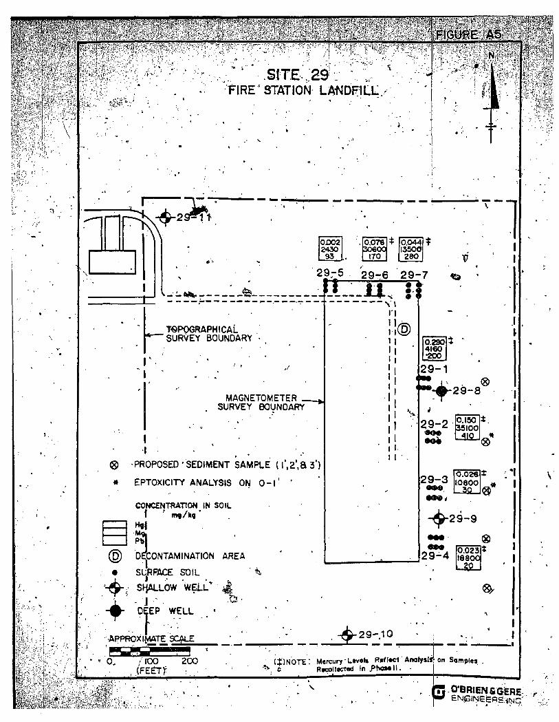
Site 29: Fire Station Landfill
A topographical survey and corresponding map were prepared for the area shown in Figure A5 ^approximately 19'acres). The fmal topo map will show the sampling locations and four monitoring wells installed at this site.
Five, 3-ft depth sediment cores will be collected from the drainage area east of the site to further define the distribution and leachability of lead in the swamp area. TTie sampling locations will be spaced approximately 50 ft. apart and will extend 50 - 100 ft. downgradient of the site, following the water drainage route. The samples will be analyzed in accordance with the protocols summarized in Table A2 and in Appendix Al. The sediment cores will be analyzed in subsamples representing 0-1 ft, 1-2 ft, and 2-3 ft depths. Lead and percent moisture will be 'analyzed on all the samples while EP Toxicity-lead will be analyzed in the top one-ft of two of the five sediment cores.
SITES 32 and 33: Area 9 Landfill and Plant Site /
Additional sampling bf soils and ditch sediments is proposed'at the Area 9 Landfill and Plant Site to further define the limits of-honzotiutaod-vertical contaminatiof\jFigure A6 shows the proposed sampling locations. Proposed sampling at the plant site includeS^s^ection of-^hfyr
-three (83) surfaQe%)"Mtrdepth) WMI oample»-«Hd- three soil borings (to depths^SJt. grdbler than the borings collected in the RI in these locations). An additional fivcvourfaoo crQaM>adim«nt6 (0-jifti d<pth>-and tWp (2) soil borings (to a depth tfiree feet below the borings co'mpleted in the RI) are proposed for the Area 9 Landfill site. Boring saniples will be split into three 0-1 ft cores for analyses. All soil samples from the plant site will be analyzed for PCBs and percent moisture. Sediment apd soil borings from the landfill will be analyzed for PCB?, lead and percent moisture. SoECn Mmples from tfeedtteaAfeandSU will be analyzed for lead EP Toxicity. The analytical procedures and quality assurance requirements are detailed in Table A2. Appendix Al includes the sampling procedures to be followed. y
The aerial topographical survey, for Area 9 included (he landfill and building complex. Approximate survey boundaries are shown in Figure A6. The area surveyed is estimated to include 140 acres. The final survey map will show the sampling locations and the monitoring wells.
/
>

I W?A/A^': ;+^4 y i
1 y
%
7
f\ f Af^y \ \ j
\ K yi(\\ ':yv:' 'TXxy:'y-mf •'1 ^ I v
\
'A
TABLES AND HGURES
A
- • • ''- Z'',iiy .i'iu:
> . 0
<
I , . i IJxg;^- k-..
: >

^ . iMtiAl
PROroSED SAMPLING^ SUPPLEMENTAL SITE CHARACTERIZATION'
CRAB ORCHARD REFUGE FEASIBILITY STUDY
n -
<a> / ^
SITE DESCRIPTION
NUMBER OP SAMPLES
SOIL/SED BORINGS TOPOGRAPHIC
HAP ANALYSES n
IS Plating Pond
17 Job'Corps Landfill
22 Old Refuge Shop
Yes
^
28 Water Tower Landfill
29 Fire Station Landfill
32 Area 9 Landfill ^,-f''^
33 Area 9 Plant Site ^ - S a *
6
10
--
5
2
3
Yes
Yps
Yes
Yes
Yes
Yes
Cr, Cu, EP Tox-Cr (Top core only)
PCB, Cd, Pb, ' EP Tox-Cd,Pb (Six samples)
Cn, Cd,. EP Tox-Cd (Ten samples)
Pb, EP Tox-Pb (Top core of two samples)
PCS, Pb, EP Tox-Pb {•SjyefTsamples)
PCB
\
Notes:
1. Sedfnienr sanple cores will b ^ analyzed in 1 f{ core depth subsainples. ' All soil and sediment samples witl be analyzed for percent moisture.
~2. See Table 2 for,ABnalytical methods and quality assurance requirements.
3. See /^{pendix A for sampling protocols.
^. Attachment C, Proposal for Topographic Surveys, includes deta4l on the topographic mapping for each study site.
\
J
^%;''0'''3'£v''i
^i;.^;H-.-\:.

$ ^ ? ' y f ' ! y ' : s ' ' ' : ' y . ' y ^ y ' . ' -• ,'* * i - . ' . . - . «,. • '. ^ j ^ . j - - - --"•
'.'•-:--ii!f.S--? i'--'i'i'ay'?!'
y < \
1
j ( / .
V
(?^-
TABLE A | ., ,
ANALYTICAL METHODS & QUALITY CONTROL REQUIREMENTS SURPLfeMENTAL SITE CHARACTERIZATION.
CRAB ORCHARD NATIONAL" UJLDLIFE REFUGE
• '. '-' - / '
PARAMETERS
Potychlorinated , Biphenyls •"
Csdmiun Copper Chromiun Lead
Cyanide
Percent Jloisture EP Toxicity (Cd,Cr,Pb)
HETHOOS (CLP>» SOIL/SEDIMEHT.^
WK h'-%
UK 87-K*+ , UK 87-K*+ UK 87-K**
WK 87-K* •
160.3« 1310#
QUANTITATION LfMIT (dtOL)
mg/kg
0;08-0.16
0.5 2.0 2.0 1,0
2.0 *' V
- IX •^ 0.1 mtf/l
AUDIT, FREQUENCY & CONTROL LIMITS
See Below
CRQL = Contract Re<^uired Quantitation Limits
(-*) >1etals Furnace analysis will be analyzed in duplicate to verify'spike recoveries. If recoveries are out'side •»/'-10X values will be determin,ed by Method of Standard Addition. I
(*) USEPA_(1987).Contract laboratory Program Statement of Work for Inorganics Analysis Multi-media Hulti-concentration. SOU-787. IFB-UA87-K-O25,026,q27.
(#) EPA-600/4-79-02t>< Methods for Chemical Analysis of Uater and Uastewatei;s.
AUDIT *
• Re'agent Blank
Matrix Spike
Matrix Spike Duplicfte
Surrogate Spike
Field 9 tank
Field Duplicate
QUALI nr CONTROL/ASSURANCE REQUIREHERTS V - ' .• '
FREQUENCY ' CONTROL UMITS
,10X of Samples
10X'of'Simitar Cor>centrat ion/Matrix •
10X af Similar Concentration/Matrix
Not Required for Inorganics
All samples and blank . (including MS/MSD)
.'Not Required for Irtorganics
5X of'Samples Provided by Sanpling Crew
10X of .Samples Provided by Sampling Crew Not Required for Organics
Less than CRQL
Recoveries B \ Specified in Methods
Less than CRQL
Relative Percent Difference (RPO) within •*/- 20X ,
W0mM
V V-'tA
<© .A
<s
• iy . . \ '
<Mfe: .

^ J T R ^ I ^ W ? ^ 1 " i r t i ' '
I FIGURE Al /
SITE IS-A^A:^ 7 PLATING POND SITEj6-iA:ftEA 7 INDUSTRIAL PARK
r •:--
A\
3^
16-
16- 16-1:
|16*-15
I t E?11 P°N° I r 1 5 - 2 } J gl5-3
16-17
TOPOGRAPHICAL SURVEY •BCaJNDARY
PLATING
t15-1)
@ " DECONTAMINATION AREA APPROXIMATE SCALE " • '
0 100 200 ' (FEET)
SUPPLEMENTAL SITE CHARACTERIZATION
a PROPOSED SEDIMENT'SAMPLE ^ LOCATION (HAND AUGER)
(SAMPLE AT 2 ' , 3 ' , a4 ' )
G bBBIENaGERii \

^^ifv:'e^-H,
If-=.^~-<^ ,-;-*' •*~'-J
-^''•x:'"^t'''^ " .w^,.>?.^,;,,.,.':*f: .....I.,,.
te?<-A-=?-%----*:i";.!f,-,-,-' •
^ m p y y ai;5:'s-ii:v'aEi;.':''*: -:•
SITE 17
0UT1,^T JOB CORPS LANDFILL CRAB OnCHARO N A T I O N A L WILOI
TOPOGRAPHICAL SURVEY. B O L I N D A R Y (INCLUDES. ENTIRE 1»0ND)
'^ ' | -J '^ '-i .--i . > ' - •
j s i ' - . ' - ' iT '^Vf-r- - ' - - . ^ \ ^ ^ ^ - s S i . « •• •• • -b?.>*--^^-.-T-''' -.-^ "•
1
v'-w^-'-V--'-
ta',':-.^x. ,-
gtSn:
. .-^. '>V'.-:VJ=r^.^.^-;
0M&^^
\ Vi
5 9 «
• SUPPLEMENTAL SITE CHARACTERIZATION
^ S H A L L O W WELL
- ^ DEEP WELL
SCALE IN FEET
I PfiOPOSED SURFACt SOIL SXMPfit ( O - T )
• * ^ A PROPOSED SEDIMENJ^SAMPLE (l',2?)
l i ^ f t C T A i ' l 1*0 S c o P C I
v > ^ ^
> ^ A ^
'-.'^.'•'f'j
] • • ' - •
/ /-
CD
m
TO;

/
t^M'^-^l/'y . ,„ .
. - SITE- 22 SAMPLING LOCATIONS
• \ V:^^'; u--. ; ^ ^
^4^:,^ v:^
•^McCowo
j l -ccDIsposaN
\ j . o - '(t af
:b^ 448
' • W ^ e r Tank
SEO'IMENT CONCENTRATIONS
Totol Cyonid* Cmg/kg) Totol Cadmium (mgAg) EP Cadmium (mg/L)
130.2 490 JLL.
- ^ S h a l l o w w e l l
SCALE IN FEET.
. SUPPLEMENTAL SITE CHARACTERIZATION
• : : r ^ ^ - ^
S X—PR0P0SE€>-5DRf»cE SOIL - SAiyiF»teie-H|
V 0 PROPOSED-SEDIMENT-^AMPtE-^OHHl—
* ^ • - PROPOSED-SEDIMENT SAMPLE (I ' ,2', 8 3')' 0 . 1000 2oeb
mm f.»8-«-sa
OURIEN&GE^' E N G I N E E R ^ INC

J ' •fj- r * '^ ' . . i .
!»PffjiP»<!»ig;.i i . i i .LLJ i . . . , . - ,
Id?. * -
U r
CI mo
.«'' n m
'-%,-.- SITE 28 WATER. TOWER LANDFILL
PHASE ] &II
TOPOGRAPHIC SURVEY BOUNDARY
v ; ^ ^ 1
Ml eaueikmflJfcrT'
t PHASE II SAMPLES
• c t i i M r n r
I I MAS^AUM.1 toa, at/k| WIT vinifT
t u i i . i u i r i e i conMun t o ^ >»»• >• ! WIMHT
I I lO*. • • ' • • o i l wfUHT ( - rn iTr iT
c
(
i->„i.,-~T;-::--M'-;,
%yy^y :y : .
^ ^ ^ y ojooa 2430
93
0.078 306(X:
170
t 0,O44 13500 280
1 p
• o ^ -
2Q"5 29-6 29-7
TSPQGRAPHICAL SURVEY BOUNDARY
r
MAGNETOMETER _ SURVEY BOUNDARY
I t
•I _ . ® -PROPOSED ' SEDIMENT SAMPLE (l ' ,2 ' ,a 3")
« EPTOXICITY ANALYSIS ON O - l ' '
CONCENTRATION IN SOIL
Mg, Pbl
@ DECONTAMINATION AREA
• SURFACE SOIL
^ , SHALLOW WELL* ^
- # - DEEP WELL . '
-APPROXIMATE SCALE
ii® I I i i • i i
29-1
" ~ - ^ 2 9 - 8
I I I I
0.2S0 4160 •200
«)
29-2 •o4
29 -3 ttM»
lo.isoi 35100
-119
O.02« 10800
30
®
- ^ 2 9 - <
(S) OQ A |Q-°23l 2 9 - 4 18800
^
, - ^ 2 9 - 1 0
0, .' 100 2C0 , .(FEgT)^ :.-.-
( $ ) N 0 T E : Mercury-Lev«l» R>fl«cl Anolyslff-on Somplej ' ^ , c Rtcoll«;t«i in P h o M l l .
T w i t ! '
•I
B -0'BRIE?SIfi(SfeRE ENpjix}eEBg,-^rjjC'

r?;:"^?T^ J S > i - T
\
fc';?S:.!?>Wi-iSx'fe.>^Kif'-i|?S**K.S^
F ! G U | E - ^ A 6 % * ^ ^
-<5 4-= -', r' - f .? yf£,
. Sl#PL^EMkNTOSS??;1^SfeSfi?'l SITE ' -\--->--=.^--V4.-.t-^H;f|Mi
CHARACTERlZATlpNii^%^J^:Jl%'y5S
LEGEND
<i&ys>^y^
n<u»natu iiiHL' 'u« !«.Li«iiii-;sfflfet£i-'! H J - T ' I — • ^•'-5'&i^CS
• . - -- '^ ;V-#.-Ai f- i i§ PROPOSED BORW^-LOCATION: ! S- ioEpwi ;
• ,-in -••-nri»-ii't-''"^'^''' - '^'^rS
l O - l ' ) f e w CP TOiHetTY-TEilV:-; !^!?^' ; !
•''•:••.-HV•:'•^'^•,'?'/•
'-iiv^vySSiS -• ; . . i i^v i?K;s^i i i ;>;a
'^ i i i»K*?P^ . . -^y^ ,:>'rL.>^^ .-':.i--^-irj.L.'ity
' iV'i*.r';.^ft'.'-,'Oi'rt'>*K,CIi<
(i -c'yr.ipyy^ymfy& i -- . . : f . ,- . ;<Jre;s;;vjvj j , f ; . ,g)^g

.r,.
. -* ->
f
ii.- •
' • i ^;'v
J"*"'
*
<-
' A J
APPENDIX A1
» .SAMPLING PROTOCOLS
^ €v' ' /A ^PilS^ li ...ft;

: J ^ y -t 5 .^ \
ft? / I 1 r
> • * * ! * .
APPENDIX Al
SAMPIJNG PROTOCOLS " SUFFLENJENTAL^SITE CHARACTERIZATION
SECTION 1.0 SAMPLING PROCEDURES
T-"} 1 1 •> i -^ i^ <
1.01 Sample Types
The supplemental site charaicterizawon plan will include collection of sediments fr9m ponds and ditches, surface s o ^ (0-1 ft. depths; and soil borings (up to 9 ft. depths). For the most part, all samples will be obtained as single'grab samples. However, at some sites, depending on the size and location of the sampling are|!, composite samples will be prepared. Compositing procedure are discussed below.
/
C
Field*blanks, field duplicates a/hd matrix spikes/matrix spike duplicates (MS/MSD) will also be, collected or prepared as paiVof the quality assurance and quality control (QA/QC) requirements outlined in Section 2. Additional control blanks, duplicates and spikes will be prepared in the laboratory to fulfill the^equirements of the GLP analytical procedures. The frequency and control 'limits for these types of"samples are Listed in Table A2 of this proposal, Afialytical Procedures and Quality Control Requirements.
Field duplicates ar^ two distinct samples taken from -the same location at similar times using identical sampling equipment that has been decontaminated in a similar manner. One field duplicate will be collected for every ten samples collected. Field blanks for sediment/soils will be prepared using prewashed, dried sand. The field blank sample will be placed into the appropriate decontaminated sampling equipment, removed from the equipment and then placed into the proper sampling containers. One field blank will be collated for every twenty samples-collectedi Matrix spike (MS) sarnples are collected, following the sampling procedure for the matrix being investigated using the same procedure as for the field duplicate samples. Samples tagged as spikes will be treated with matrix spiking solutions in the laboratory and will be analyzed in duplicate (MS/MSD). One matrix spike sample will bfe collected for every twenty samples. . /
1.02 Sampling Procedures /
Soil and sediment sample^ will be obtained by compositing subsamplds of approximately equal volunies taken from 2 to/s (or more) points spaced equally alGng a cross section chosen to be representative of the sampling location. "Die size of the cross section may be modified depending on the location, size,/topography, or offier field conditions.
A disposable 3/4 inch diameter plastic core will be driven vertically at the sampling location to the required depth (0-6, 0-12, or 0-24 inch fJepth) for the surface soil or sediment. Bottom sediment samples frop ponds will be obtained using a sediment dredge sampler lowered at the desit'ed location (s). Test soil b<)rings wUl be obtained using the. hollow stem auger drilling method ASTM D-1586/Split Barrel Sampling described Ln Attachment A to this appendix. The grab subsanfiples may then be composited in a disposable aluminum pan, using a large stainless steel utensil to homogenize the sample. The composite sample will be placed into a labeled, prewashed glass sampling container for analysis.
s-r:&'>?4*:«x-.;v'-

C^S^A;A ' ' l^^ftft8l!WSK^t*S-^"i^?^ f ^ ^ ^ i ^* I , ? f | $ ^ - : g K r : ; f ^ ' ; ' - " .; . - : ^ • • - • ' . • • • • ; . .- • ' . - . ; . ^ .• • • • i y . y - ' "- - . i- •«• J ' ' i ^ iKr^^^ - ; - ; ' ' " . - '-^ - -' . • . • ; J . . ' , - . . . „ "
K - ^ ] ^ ^ ^ ' ; r - ' ! s ? - ; - • • " ' ' " - ' • • • • ' ; ' ' • • ' ' ' ' ' ^ ' . - - ^ ^ .
., f Appen iix Al-^ Pagi:Al,-2^
The sealed samples should be stored in an insulated ice cooler at 4 degrees Celsius. Ail pertinent mformaition should be recorded i in the sampling log book and chain of custod^i fc including sample collection date, location and identification. Sample preservation, corfla and trainsfer of custody requirements are detailed in the following section.
forms, imers
1.03 Sample Control 1.03.01 Sample Containers and Preservation
Sample containers and sample preservation may be different for each type of analysis to be performed. Care must be taken to utilize the correct sample container(s) and preservative(s) to ensure the integrity of the samples. Table Al-1 provides a listing of the sample preservatives . and the sample containers to be utilized. Sample containers will be supplied by the contract laboratory. The collected samples will be kept out of direct sunlight and, after decontamination anjl labeling, wiU be placed in coolers for shipment to the contract laboratory.
1.03.02 Sample Shipment and Chain of Custody v.
Samples will be packed and labelled according to DOT regulations ajnd protocols. Samples will be shipped via a 24 hour delivery service *to the contract laboratory so that the samples can be extracted within allowable time limits. Table 2 lists holding times for the specific analysis to be completed.
Chain of "custody procedures must be followed closely to ensure that an accurate record of the collection, transport, analysis and disposal of the sample(s) is documented. The chain of custody procedures include field custody, laboratory custody and evidence files and conform with the procedures outlined in NEIC Policies and Procedures (EPA-3309-78-001-R).
Samples are accompanied by a field chain of custody record (Figure Al-1). When transferring the possession of samples, the individuals relinquishing and receiving will sign, date and note the time on the record. This procedure documents - sample custody, transfer. Samples will be packaged with a separate custody record accompanying each shipment. All shipments will be accompanied by the field chain of custody record identifying its contents. The original record will accompany the shipment and a copy of the original record will be retained by the Project Coordinator^
Whenever samples are split with a second laboratory or with a government agency, it is noted in the "Remarks" section of' the custody record. The note indicates with whom the samples are being split and is signed by both the sampler and recipient. If either party refuses a split sample, this will be noted and signed by both parties. Th^ person relinquishing the samples to the facility or agen^ sliould request the signature of a representativfe of the appropriate party, acknowledging receipt of the samples. If a representative is unavailable or refuses to sign, this is noted in the "Remarks" space. When appropriate, a^ in the case where the representative is unavaU-' able, the custody record should contain a statement that the samples were delivered to the designated location at the desi^ated time. '
A. . • ' . * If the samples are sent by mail, the package will be registered with return receipt requested. If sent by common" carrier, a Government BQl of LadLng'will be used. Freight bills. Post" Office
t , . . 1 ' , ; ; - ; . . , ,-,, ;., . -
j^£00§SikyM'. i'j'vwj ''' \-AA-^''y' '- 'A •0i&^M^yA^AA

•^ijyjjiimi Jill UI IIIw m m .mi , « . u m III. i | II
i-ri h' ' ! | | | ? 1 '-,1
l).-^i- l .^-^--;^*^>: ' lSti%:-
A-Apf.endixAl
I'ageAl-3
receipts, Bills of Ladmg, and cham of custody records will be retained as part of the pfermanent documentation K the samples are delivered to the laboratory in person, this will be noted in the cham of custody record
. mmy - :y^mi • ^ y y - ^ i
< • #
/
' ^ I 'W^^ iCJS^^ ' •-•-- •'•-.;'/,.
-. / /

A A " ^ i ^ 4>>'1'~"' '* f
f^TT /- «* ii 'JiTJS.ii i'HJ<--^h''
S 1.
Appendix Al Page'A1-4
SECTION 2.0 A^JALYTICAt PROTOCOLS. OUALFTY ASSURANCE AND CONTROLS
2.01 Calibration Procedures , . 2.01.01 Equipment ^
All fi^ld equipment will be calibrated in accordance with the manufactiirer's in'Sttuctions. Any field Equipment that is not covered hw^he investigator's standard operatmg procedure will have
"''a specific calibration and operation iifstruction sheet prepared for it. j
2.01.02 Standards
Standartls may be generally grouped into two classifications: primary and secondary. Primary standards include USP drugs, NBS and ASTM materials, and certain'd^igijated .EPA reference material. AH other standards are to be considered secondary. No testing bf primary standards is necessary. Secondary standards will be examined when first received, and less stable standards will be rechecked at appropriate intervals, usually^ix months to one.year.
2.01.03 Records y
A records book will be kept for each standard. Each record will include name and date received, source, code* or lot number, purity, testing oSta, special storage/requirements and storage location. Records will be kept on each instrument requiring calibration, to record all activies associated with maintenance, QA monitoring and repairs program. I •
2.02 Analytical Procedures - /
The analyses and methods detection hmits for analytical pptameters are given in Table A2 of this proposal. When analyzing samples by the listed star^dardized methods, the accuracy or precision of the data generated by the laboratory is det^irnined through analyses of replicates, spiked samples, synthetic reference standard samples, arjti field and laboratory blanks along with each set of samples. Any interference is identified ahd documented. The required QA/QC samples to be collected are specified in Section 1.01. /
, / /
2.03 Internal Quality Control / '
2.03.01 Analytical Procedures and Laboratory Quality Control % •
The quality control objectives for the supplemental site characterization program are listed in Table A2 of this proposal. The frequency of replicate samples, spiked samples, reference samples and blanks, as well as control limits for acceptability are identified in this table.
Quality control data reports, which include aU raw data.reports, analysis of EPA standard reference materials to veriiy initial calibration of CLP analysis, and reports of blanks, duplicates and spiked samples will be included with each package.

mMm?y^^}>!i--i;y:y^yy^"^^ m'iSit^r^i^ykrx'y.tyy'^'y'yx'^y - •- ,-"••-? .
I
' yfM
2.03.02 Field Control and Preventive Maintenancfe
iUpKSi '-MyMAB
Appendix A l Pag^Al-5
r
Field sainpling crews will be under the direct supervision of-a crew chief. Photographs and sampling [Records will be used to document all sampling activitid!s. \
Preventive maintenance procedures will be carried out on all field equipment in accordance with manufacturer's equipment manuals. Any field equipment that is not covered by the standard operating procedures will have a specific maintenahce instruction sheet prepared for it. ,
2.04 Data Assessment and Validation
Data assessment will be based upon instrument tuning criteria, duplicate samples, surrogate recoveries, matrix spikes and matrix spike duplicates. Any data tha; should be rated as "unacceptable" or "preliminary" will be identified. Corrective actions will be identified if required.
Corrective action procedures are developed on a c^se- by-case basis. These actions may include:
- Reanalyzing samples if holding time requirements have • » not been exceeded. V"
- Altering field or handling procedures.
- Resampling. '
- Using'a different batch of sample containers.
- Recommending an audit of laboratory procedures.
- Accepting data with acknowledged level of uncertainty.
- Discard data.
2.05 Data Reporting.
Copies of all documents and raw data from the laboratories performing specific analysis will be included in the Feasibility Study report. These data records will be filed at the Refuge headquarters under the custody of the Refuge Manager. The data results and the quality assurance and control support documentation will include:
- Discussion of accuracy, precision, completeness of data and results of perfbrmance and system audit.
- Raw data results ahd support docuhientation. " .
- Chain of custody forms. . ' -
• Discussion of results of data assessment.
*^ .
h •-

I-
i .«
» • i
Apf)etidixv\;i |!;" I P i S i
;t &mm m ¥ HI?
<;
TABLES AND RGURES
'I skm

- y y ^ ' - y y y : ^
K u r i l
>«r««tUr
? ^ l m - h ( m l l a l
•ol^ftll i (MUr)
.( V a U I I I s i ( M i l l ,11
|g^»C7t« ' ^ (w i l ) ' :
• OKWtCt ' . Dr l>k l t , : iC l „
•gti > i a i / M n n ) IS«4I«> U l a i a l l j i i r l ' I l o t h t t \ ) t t ! i m m C l a t l Ql / • « « l ^ f l M l l na r C l a i t Qt /iioiia l a r i M l i «« r
Ca«(al«ar/Pn
nal v la l» / i *«a
H i U l a f - I f«» .
I< ttTI
n U n
-. > ««.yl
' i i tan
<tolUI
KCklU)
^ywi
a
IKtel , .
o a j a n i • HaiarSwt-BaaUa
M I 4 l a ( I l a a
f a T S t i r l
Sii;|#?i?;.(a.M)-'
' a t e l a l a l i / a i
•Oal i l a l t / a <
Claal m./mom l a r i M l l M r
Wd. Jar/««fiv l a f l M liMar
;•Cla»> 01./nan* -laflOM l l n v r
.TlaVi «!./>>»» >la'la« l l»tr
t U i t qt./aaM l a f l a * l l na r
W4. Jar/i>4«a I t r i M l l w r
C l a n « t . / > a v
ftec C l i i i / no t i i - la f loB iaeta
'>>ra«»tar C—U|p<r /yraa.
i ' j-y<^ or^»»<iti*t.:
i j f i f tSatl i l i l f jJlalui-
.^i^.:'^f.^ir«pit-r-e'lv^a'-,;,-^- •
r iait i</wni] «• HI <l Clata/««nf r ar i/mmm
9 Of C/RMa
r ar WjMiH
la <ar>
la a./i
l« 4ar>
u <ar>
> <ar>
I 4 tn
u tori
K. tar i
i« tor*
f ton>
l< tori
' -ton
» «ar«
t a l o *
« ^ i r t » , ,
JOt
•1(1)
•O-UJI
'|jaa»;
IMal
lOOi
IMal
MO,
I U R I ' Pail
"i »•
.rtMfn*
I " t i o . i
n t i i i i o i i
. mai i j iMs
• O I . W ^ . I M . T I C . I I I . V ) . I
Mio.aoio. iw. I I I . t o t . ' t i l
i>0.>oa.«}<
>f0.io>.«iaa.
. ' H I !
i n
MM. .a t l l
U I
I I I . - fCIl
K l
K t . . X l l
ra i l t c l to i .
I. • K n
• i t * . i M l f .
AW
> I I > « « » I I 0 » t i l l
Varaotar
C«l l-C ,
Uat 4-c -
teal a-C
IDl
f a t a b U l a , I I —
I I tor*
6 watkl
AfMl , f t • ••aaiatair
lOOkl
. l«0>l
lOOal
I t - I
' *•/•
AMal/ia • • M a l a l a i r
SXOB
W»(C« MCI
r i l t a r a k l a . l a t a ) , ao.,. K l l a t a a l a , f a l a l l l a
H I It
l l>*
IMU
»«1
0 4
Ual a-c
(Ml a-c
C M I a-c
C M I a'c.
CMI a'c
Uo\ cc
C M I 4-C
Uoi a;c
Caal 4'C
(aal a-c
U«l «"C
c—1 a-c /
C M I <-c
C M I a-(
Col a-c
(••I a-c
Caal 4-t <a«l l-C too l a-c (aa l t-C
( • a l 4-c
C W « a l w H t M * a l a « t
^ f < ^ r - Olatalw*^
Ar . ia t t ,
* t » t i i * i i r '
0 .a«l to
CHiavlto
CNlariAa
Craaiaal
MaOrlav
• l l r a f r , t a a X a
4 J a l t o * l . l a l a l
" l l r l l a t i a i a i t r a t a
• i t r l l a
^ h a i ^ t a
latal Pkataiiaavi
MMc. .
i a i l a i a
i a l ' l a a
i a i ' l l a
too
COO
o n t Craaia
l a l . l O^aalc Car*M
Ptk«M«llci
, Cs«tal««r/rnaa.
H a i l l c / l » l laWJ
r ar t / a m
P ar t r i a l MMl
IWa KIM. ! .
l l l K I a , -l l »
1 M M > I
I 4 l W i X ^ > -
n tor<
>al<aB
7O0»r
noai lOtel K t ^ t
leoai
Olivalaaa Ulpantoa l a l a l
C I - W l
w
i M I a .
OKI 0« l 0»t -
Ot l '
f t
r«M-Tall
C I 4-c
r i l l « r I M I 1 . pH /
C a » t a l T / r r T , ,
f • . ( / • » . •
P ar t/,i0nc
P ar t /Mna
P a r ' C / M * *
P ar i/*aMa
P l a i l l c / l a l U W
P ar C e » »
P ar v i a l Kn04
P ar t / l a l Kn04
P ar t r i a l >no4
» af «rt») Mn04
P or 6 / lB l HfMa
P ar traara
P t f t r i a l R7VM
P l i i t i c Chlr/aaM
P ar t r a m
P ar firlai;aaC
P ar t/aaaa
P ar t/aoaa
P <r t r ia l mn04
7 t l 4 i | Plalft/ l a l >irw<
la r iaa l laar
P ar l ^ l a l Kno*
Gia«i Ol / l a l anoa la l laa l laar
toWla, ^ l l a .
14 tori
14 tori
r t tori
n tori
*aal>ia l i ^ l a t a l y
I I tori
n tori
10 tori .
n tori
n tori
JO'topa
n tor«
10 tori
' * - n
•aa l r i a
l « a 4 l a U 1 r
U i M n
f t tor*
n tori
n topi
I t topi
lie o i ^ m t u i o
t a l o . Oapal r^ I t t te l
• r t p . l a r f l * .
« M I lOOal
W ( k l
lOOal
Wal
M a i
« k l
10.I
MOal
t o i l
n a l
tOIkil
lacto
l«U
CI
Chlart CintK Calarlaal ( I I
• O I W ]
• 0 1
• 0 1
f04
P
" l l O J
W4
i
M l
K m . i o o n
COO-K
roc
PMCaBl
o n
OPl
( M l
(••I
Ctol
Ca*l
Caal
Gaal
Caal
(••1
Caal
iaal
Caal
Ctol
.Ctol
Ctol
Ctol
(••1
Caal
4 - {
4 - (
4-C
4 - (
4-C
4-C
4-C
•-<
4-C
4 - (
4-C
4-C
4-C
-c
4-c
» a" t — ' •
n >

f s
LABORATORIES, INC. / . ' / ^HAIN OF CUSTODY RECORD
' } j i i > '•"•:. .OBG Laboraio/ies, Ine -•••Vfi'ox'48-73 / I304''6uck'.ey Road ' Syradase'.'- Je'.v York I322i .' (3 i j ^ 457 1494
' / ' t l ^ 1 ^5^0aKd !e^ leC:caJ'•Bulld>nQ / 700 Harry L P^^>\/Jchnson ejy Now >\rk 137 90
SUR^Ef - - SAMPLE.RS: ,'S.,«ii-.. 1
- • • • • - -• . i • " . / • 1 «
SfAf lCN
f
•
.
'* ' , l U n O M IQCA.'ICfl
• 1 -
•
X
•o*tt ' - . '
-riMt
SAUPK ITP(
. w V - r •
CoMa, 1 Or«« -
I
i 1
k*1 1
! •
1 .1
i -! ! i '
j
d CCNIA INWS
1
f<AlTSl$ •
,
- ^ . ' ^ ^ ^ 1 1 • 1 . •
1
«
• ! - \ . • •
.1
1 i ' i - i ! 1 ! •1 ' . i i 1 i
1
• 1 i 1 i ! i ! i
Reiinquisheci b-/: /s;,m.iw;ai
Relinquish«ci by: fSi rwrvrai
Relinquishad by: fs.f«.»v.»)
Re l inqy i i r Jd by; • i^ 'x i 'v ,
O i i p o ; < h e d b y : rs.yoapv^i
1 1 !
.
I
Received by: (.,,«,«,„/ Dare/'Tirre 1 1
Received by- ;;»-•.».•, j D<3(e/Tine '
Received by: fs.,«.»-/ | Ccre/Tl.-ne • ^- 1
.Received by ,'«<obile LabofOiory for f ieid c n o l y j i j ; ,J.7.~J'V/«I
Ooie/Time
Date/Time • Receiv»d for Loboratorv by: Cafe/T; in«
1 i ' • r ' 1 N'orhod of Snicjme.-^r; ' '• i '
^ - . ^ : _ - ^ . '- , L_

lOOlffinc ^ IISHCII«0 l « t l S-TRtCuSC NT I J O i '
"r mtrKoni »«t*cooi iii/»i; i«j»^ , - . s . .
'•r
-HOISTING PLUG
TOOL BOX
<» . \
/ • '
. . r**-^
-DRILL ROD
•SPLIT BARREL SAMPLER
ft
.^1 i f . I iWifc
Split barrel
sampling The fol lowing fKcerot i j re from "§ t jnd» fd Meihcd fof
p«neu»Uon ( t i t »nd i p l i l barrel «mp l in9 o( soil i . "' (ASTM dJi igf iat ion. D I58&5 -7 AASHO Opjignoi ion: T-206-70.1
1. Scope 1.1 Th i i method dejcf ibej i procedure' (or. uung a split-
barrel umpler to obtain respresentalive umples of soil for identif ication purposei ancj other laboratory testt, a n d ' t o obtain a measure of tfie retist ince of the soil lo penetr t l ica o f . the sampler. • ^
2. Appwa iu t 2.1 Dril l ing .Equipment -. Any dri l l ing equipment shall be
acceptable that provide] a reasonably clean hole before insertion of the umpler to ensure that the penetration test it performed on u n d i s t u ' ^ d soil, and that wi l l permit the drlvif>g of the sampler to obtain the sample and penetration record in iccofdane* w i th th« procedure de^ r ibed in 3. Procedure. Xo avoid " w h i p s " under the bloip" of the hamfiwr, it is rec»m- ' mencJecJ that the dri l l rod hav« stiffoest equal to_ or greater than the A-rod, A n " A " rod it a i jd i low dri l l rod or "s tee l " having an pu(sic)e d iar rwtero f 1-S/8 in , or 41.2 mm and »n inside diameter of 1-1/8 m. or 28i5 m m . through which the rotary mot ion of dri l l ing is transferred f rom the dri l l ing moior to the cut l ing bit. A stiffer dr i l l rod is suggerted lor holet deep«r than 50 f\ (15m), The hole shall be l imited m diameter to berween 2 1 / 4 and 5 i n . 157,2 anil I 52mm) . -,
2.2 Split.Barrel Sampler — The ump le r shall b» con-stTucied wi th the dimensions indicated (in Fig. \ .) I h t drive shoe shall bo of hardened neel anU shall be replaced or repaired when it becomes denied or du tor tod . The coupling head shall have four 1/2-in.-112.7mm) (minimum diameter) vent p o r i i ' i n d shall contain a ball check valve. II sixes other than tha 2'-in. (50.8-mm) umpler are permit ted, the sixe shall be 'conspicuo'jsly noted on all penetjraiion lecordi .
2 . i Drive Weight Assembfy - T^e atserpbly shall consist o< a 140-lb, (63 S-kg) weight, a dnVing head, and a guitle permit t ing a free fall of 30 m. (0.76 rn). Special'0recautions-shall be taken to ensure that the energy of i h i fall ing weight is not reduced by fr ict ion between guides.
2.4 Accessory EquiorT>ent - L
the drive w t i j M and the
ibels. d a n shee*.-,. u.mpie/, jars, paralf in, and other necessary lupplies snould accompanY; the ump l ing equipment.
•yyii-s,;,my:
. 'p ' - iy i :
'oal-'SjifeS,-•--6'- • : ' ^ ' ~ i , ' ' i 'fefe

\
»»LITHl«*CV At
> - t ' (a>ll>l
i » , I a , , . I .^ C O * ' C O W I T M » u t T C X i A I . A»I.T
_ 9 ' S M O A C X A D O K C S S O ' 30 TO 4 0
\ K - n * ( • . . • 1 \ o p i H \
Note 1 — Split barrel may be 1.U2 in. inside dumi^ter provided It contains a'lmer of IS-ga^e wall thickness. , :
Note 2 . - Core retainers m the driving shoe lo prevtnl loss of sample ar-e permitted. '•
Note 3 - The comers at A may be slightly rounded.
r is>.( l> I 0 K S r STB'CUSr K t l - tOM
l l l i P M C h t I R t t COOl J t i <J» I ' . ! *
Table 0/ Metric Equivalents.
In.
l / l 6 l tEga ; i )
\n 3/4
' 7/8
1-3/J '
1-1/2
Mm
•1.5
12.7
• 19.0 .
22.2
34.9
• 38.1
Cm -
1.90,'
2.22
3.49
3.81
, - , . » . . A , r. ...
^ • i n .
2
3
S
18
27
Mm
'. . . S8.S8.
1 , • ' '
Cm
' 5.08
7.62
15.24
, 45.72
Fig. 1 - SianOard Spin Strri l Samolrr AiitmOlY
'%»,
V ^ ' ' ^
f
^ . ^ • i ' ' 4 }
\
^y
3. Procedure 3.1 Clear out the hgle to umpl ing elevation using equip- '
meni that wi l l ensure, that the material to be sampled is not disturbed by the operation. In u tu ra ted ' sands and silts wi thdraw the dn l l b i t slowly ^ prevent loosening of the toi l around the .hole. Maintain t h e | ^ / e r level m the hole at-or <bOve ground water level.
3.2 In no cas< shall a boitom<)ischarge bit be permuted. (Side-discharge bits are permissible.) The p'oceis of jetting through an open-tube sampler and then ump lmg when the desired depth it reached shad not b« permitted. Wttere easirtg is used, i l may not be driven below ump l ing plevanon. Record j t ^ r * Iq t i of circulat ion or excess prcli'ure in dril l ing f lu id durinjtadvancing o iho te t .
3.3 With the ump le r resting on- the 'bo t tom of the hole, drive the lampler wi th b low i f rom the \ i l ^ } » (615 kg) hamper fa1lir>g 30 m. (0 76 m) unti l either 18 i>^ (0.45 m) have been penetrated or 100 blows have been applied.
3.4 Repeat this'operation at tntervais not longer than 5 ft (J.5 m) In homogeneous strata and at every change of itrata.
3 5-Record the riumber of blows required to effect each 6 n (0 iS.m) of penetration 'or fractions thereof. The first 6 m. (0 15 m) ts considered to be a seating drive. The number o f ' blows required for the second and third 6 m; (Q.IS ml of penetration added it termed the penetration resistance. N. I f ' the (ampler i i driven lets than 1.8 m. (0-.45 m),,the penetration r«>sianc« is that lor the last 1 ft (0.30 m) of penetration (if l e « \ h a n 1 ft (0.30 m) n penetrated, the logs shall state the numfci^.r of.blows and the fiactiQT.of .1 ft (0.3Clm) penetrated).
3 6'\Bring the u r n pier to the surface and open., QesaiC* carefully lypicaj. u m p l e i of soils recovered as to compo.tition, structure-j; coniis-tency, color, and condit ion, then put mlp i,ars w thout .riiTirning,.Seal-them w i l \ w a i < or hermetically S M I 19 preventvevappralipn of the soil rnorstuN. Af f i« labels to rhe faf
. ' $ ^ ' . y y * ^ ' . . •••• ' ' ' • ] ' y y t ' ' ^ \ 'a|j;;i|al;/|fi;;r,.. ;., r - - •. •.,. •:• • ' , v
^s*•£,-tel-l«,«'>i•l--s-t,'-.•i-.''.-.•'^.;'>.^::',l;•>i•;.,- L;- '. i .W
or make notations on the covers <or both) bearing jot^ designatiOfVj, bofing nomt>er. umple number; depth pene^ nat ion record, and l e n j ^ of recovery. Protect samples agamst e»tieme tempetatu't changtv.
4. Report 4.1 Oaia obtained in borings shall be recorded m the.field
a'>d shall include the fo l lowing: 4.1.1 Name and locatl6n of job, 4.1.2 Date of boring - start, f inish, 4.1.3 Boring nprnber and coordinate, if available, 4.1.4 -Surface eleva'tion,^f'><vailable, 4.1.5 Sample number ari?rdepth, 4.1.6 Method of advancing sampler, penetration and re
covery lengtht, 4.1.7 Type and siie o( umpler . 4.1.8 Description of soil, 4.1.9 Thickness of layer, t 4.1.10 Depth to water surface; to loss of water; to artesian
head; time at which reading was made. 4.1.11 Type and make ol machine. ,, 4.1.12 Sue of CJsmg, depth of cased hole. 4.1.13 Number of blows per 6 m. 10.15 ml 4.1.14 Names oJ-"?rewrTwn. and - ' -4.1.1,5 Weather, remarks. . 1, '
Undii IPX lundj'ditaiiopi c>'OCK)u'r el uno«r ii>« lu'iid'iCiiot ol ihf ASTM Commii l o r E r i g i r s e t n n g P ^ r o o K l - A l ist o t m(rT)t>*r t Vur Book.
Cv»i«iM »dii.on tcctoifd Ociooei 20. 19^7 O'-ginaiiy . i i i r td. 19S8 Rtoiacti D-1586-WT.
ihtSocif tv. iKii mfihod n i t i 0 18 on.^Soil.and Rock
i n t V be l o u n d •« I h t A S T M
•IS'. f-i'"jyii , -' y y y ' i ^ y m ^

y^t%>' # t ^ y ^ ^ ' y .
^ \
j -St to
ttt-y tA-:
- ' ? • '
.*
A
J N ," >
ATTACHMENT B ,
TREATABILITY TESTING PROPOSAL
• % .
» • • . /
y-/- • W ; yy:^

y --* ' ' = rl
'J ^-v
fcl4' « A ,1 '^'• ; J - , 1 . -f J » if '^ ' • \
f i^J 'a . ---" i- sfl-**
V 1^ ' \ A i Jl t ^ *'
i
^ ^ l l
ATTACHMENT B
TREATABILrrY PROPOSAt Crab Orchard National Wildlife Refuge
Feasibility Study
i"^ i
As a result of-discussions held in recent meetings on the Crab Orchard site, the need has been es^4>lished for bench-scale treatability tests to determine the feasibility of treating the main
'^minants in soils at the Refuge. This attachment details the proposed scope of t ;sting to be conducted as part of the Feasibility Study (FS) underway for Crab Orchard
The contaminants of concern at the seven sites addressed in the FS include cadmium, chromium, copper, cyanide, lead and PCBs; The proposed remedial technologies selected for testing would evaluate" detoxification,-solidification, or leaching of these contaminants from soil/^diments. No other matrices (ground water, surface water, air, biota) were found to represent a concern for remediation based on the results of the Remedial Investigation.
Incineration and solidification tests will be conducted with soU samples from Site 17 and Area 9 where the indicator contaminants include PCBs and lead. Solidification testing will also be conducted with samples from Sites 15 and 22 where the indicator contaminants include chromium, copper and cyanide. Samples from Site 22 will also be tested for treatment by cyanide destruction. Finally, on-site clays which appear suitable for capping borrow will be characterized. '
{
The proposed treatment technologies -wiil be evaluated on the bench scale to determine preliminary feasibility and performance. Table Bl provides a treatability matrix for the proposed
. testing. This table summarizes the proposed test and analytical parameters to be completed on the raw pastes °and treated samples.
Site soil and sediment samples will be collected in order to conduct the treatment tests. Control (clean) samples from each site will also be collected .and treated using the same procedures as for soils containing contaminants, as a b^sis for comparison to determine possible matrix
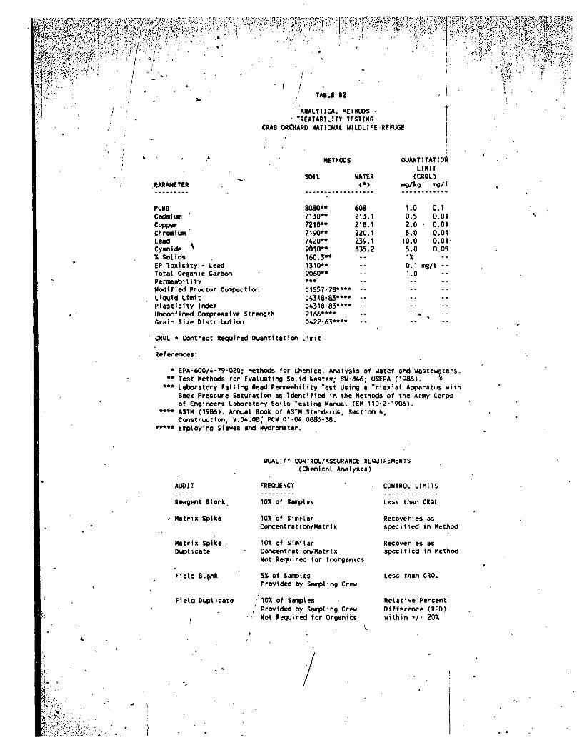
\interferences and effectiveness of treatment. Sampling, decontamination and health and safety procedures'will be performed in accordance with the site Quality Assurance Project Plan (QAPP) 'of'November 1986. Table B2 lists the analytical procedures and quality assurance objectives. The required QA/QC support documentation is also summarized in Table B2.
^ Ali testing procedures, analytical and quality control support documentation will be reported together with the results and recommendations in a draft letter report. The fmal report for the treatability tests will be incorporated in the final FS. Report.
» ' _ The testing tan be completed in approximately foUr weeks from the time of authorization to proceed. An additional four weeks will be required to complete all analytical procedures. Eight weeks are estimated for completion of this scope of work. '
-t T, ^
J-r
{
^jJi^TTHftSi -'
s-t^y-C;:H3 tH?:-

4H. " i ^ y ,
-• J- ' .)>•'•••,-•/ '•• ' ' • i ' ' C \ r - - --
A -
V i - f J ' . ;
m
TABLES AND HGURES
>
..-^
m$0$f-hy yi^&^y:by ^!-Uyiyi^!>:ri'!!?y\y i i ^ y ;»'••

y ^ I ^ - > r " • '
' " " - ' - - ; ' . ' - • , ' ; ; - ; - ' . • • i , ••• '
TABLE B1 ( p . 1 of 2>
TREATABIL.ITY MATRIX CRAB Of!CNAR0 NAtlOMAL WILI
I . CAPPING BORR0C{%
REFUGE
^
Analytical Parameters Test Samples
.-..s.v-[^,?'V-^*,
Modified Proctor Conpactfon Test Laboratory faUir>g Head PertneabUity Test (using a trfaxial apparatus with back pressure, saturation.as identified in the Methods of the Army Corps of Engineers Laboratory Soils Testirrg Manual (EM 110-2-19O6 Appendix 7)) Attert>erg Limits (Liquid timi t and Plasticity IrKlex,) Grain size Distribution
Collect two satrples (2 to 4 foo^depth and 8 to 10 foot depth) with backhoe at selected locations at Sites 15, 22, 28, 29, and Area 9 (See figure 1). Specific locations to db detenrined bssM on applicsjfele criteria for borrcur area.
II. INCINERATION
Pilot Tube Furnace
Test Parameters Test Samples
- 1200C Furnace Temperature (At least 2 seconds resicjence time)
Two s o i l samples each:
- Area 9 L a n d f i l l ; F igure 5 : 36-10 (PC8-Pb) and 36-67 ( c o n t r o l )
- Area 9 P lan t ; F i g . 6 : Sanples No. 86 (PCS) arKi No. 93 ( c o n t r o l )
• S i te 17; Figure 3: 17-54 (PCB-Pb-Cd) and 17-60 ( c t x i t r o l )
V
Analytical Parameters
Lead (feed and ash residue) PCBs (fe«d and ash residue) EP ToxtcJty (Pb) on ash residue X Sol/ds of residual
NOTES:
V See Q u a l i t y Assurance Pro jec t Plan IQAPP), Noventoer, 1986, Sect ion 4 . 0 i fcM- safflplir>a procet^res fo r sed imen ts /so i l s .
2 . See QAPP, Sect ion 5 fo r Sample Custody procedures and records..
3 . See Table 2 f o r A n a l y t i c a l Procedures and OA/QC requirements.

;s&*nws*«j ::J^syi'jy^ f^!syyKfy\$yy E.iV'rf!-,',f,"----»i*>'-T.iV'i-L>!i'..
; % ' ' - • ' - • ' • - '
\'^^:i'ifyy''' y ' \ 0 \ ! ^ ^ y y 'S-'S'- :•'"':' «?-;!• : - -
Wity^'y^) *-yy[
|/.;);,-.j.-rF7,'i..
TABLE 81 (p. 2 of 2}
TREATABILITY MATRIX CRAB ORCHARD NATIONAL UILOLTfE REFUGE
y y ^ u y
,-•' i
! : . 1 . '
• J , - -
fK'c-feB-:;.-.'"-,!-.-. .II"---..--;.-.
l U . SOLIDIFICATION
A. PCBs and Lead Wastes
Tes t ing and A n a l y t i c a l Parameters ' Test Sanples
A
- F ly ash/l ime/cement ac id i t i on . (25-100X w/w dosage) '
- L e a c h a b i l i t y o f raw artd s o l i d i f i e d sanples (PCBs, Pb analyses on leachate from co l in r i t e s t s )
- Voliine increase and uriconfined . coatpressive s t r e r ^ t h of s o l i d i f i e d samples
- X So l ids of raw and s o l i d i f i e d sanples - Tota l Organic Carbon of raw sairples
Two soil sanples each:
- Area 9 L a n d f i l l ; F igure 5: •36-10 XPC8-Pb) and 36-67 ( c o n t r o l )
- Area 9 P l a n t ; F i g . 6 : Saofiles No. 86 (PCB) and 93 ( c o n t r o l )
- S i te 17; Figure 3: 17-54 (PCB-Pb-Gd) and 17-60 ( x o n t r o l )
B. Cadniun, Chrcxniun, Copper, and Cyanide Wastes
Test ing and A n a l y t i c a l Parameters Test Sanples
Fly ash/l ime/cement add i t i on -(25-100X w/w dosage) Leachability of raw and solidified saofxles (Cd,Cr,Cu,CN analyses on leachate from colutr tests) Vol Lane increase and unconfi r>ed compressive strength of solidified samples X Solids of raw and solidified samples Total Organic Carbon of raw samples
Two soil sanples each:
- Site 15; Figure 2: 15-1 (Cr-Cu sediment) and 15-4 (control)
- Site 22; Figure 4: 22-5 (Cd-Cn sediment) and 22-9 (control)
Test Parameters
IV. CHEMICAL OXIDATION
CyanicJe Destruction
Test Samples
- Myp<x:hlorite and Hydrogen Peroxide - 2 to 3X Stoichiometric Requirements . - Alkaline p«i (with NaOH addition) - 2-3 hours mixing time
Arsalytical Parameters
Cyanicje (free and complexed) on raw and treated sanples
NOTES:
Site 22; Figure 4: 22-5 (Cd-Cn sediment) and "22-9 (control)
1 . See Q u a l i t y Assurance Pro jec t Plan (QAPP), Novenfcer, • 1986', Sect ion 4.05 fo r sampling procedures for sed in ien ts /so i l s .
2.. See QAPP, Sect ion 5 fo r Sample Custody procecdures and records.
3.««See Table 2 for Analytical Procedures and QA/QC requirements-
i-f W ' , 'j ' " : V t •• ' • ; ' ;S-;s . ' '? i^i ' - --- ' ' - - '" , r ; . - '
/fr.
•.•','' '•'- • • ' . ' ' . ' ; " A . - ^ f ' r ; - i ' - ' ' : - -fWpiiapiiipiiiipi
\ i ^
:> y "l
r'^f • I /
TABLE B2
ANALYTICAL METHODS ' TREATABILITY TESTING
CRAB ORCHARD NATIONAL WILDLIFE REFUGE
...,-, v,.-,B^KgS
&'
St'f-'\
s/jj-jj-f'-;
^t0;:
METHODS
SOIL
Rnffn** 7130** 7210" 7190** 7420" 9010" 160.3" 1310" 9060**
•*• D1557-78*"* 04318-83"" D4318-83**" 2166"«» D422-63"**
UATER
(•>
608 213.1 218.1 220.1 239,1 335,2 ------
------..
QUANTITATION LIMIT (CftOL)
mg/kg
1.0 0.5 2.0
s.o 10.0 5.0 IX 0.1 1.0
--- -.«
mg/l
0.1 0.01
• 0.01 0.01 0.01 0.05 --
mg/l --
---. ---. --
""
RARAHETER
PCBs
CadmluR ' Copper Chroniuii Lead Cyanide * X Solids EP Toxicity - Lead Total Organic Carbon PermeabiIi ty Modified Proctor Compaction Liquid limit Plasticity Index Unconfined Compressive Strength Grain Size Distribution
CRQL > Contract Required Quantitation Limit
References:
• EPA-600/4-79-020; Methods for Chemical Analysis of Water arid wastewaters. " Test Methods for Evaluating Solid Waste?; SU-846; USEPA (1986). ^ "* Laboratory Falling Head PermeabiIity Test Using a Triaxial Apparatus with
Back Pressure Saturation as Identified in the Methods of the Army Corps of Engir^eers Laboratory Soils Testing Manual (EM 110-Z-1906).
" " ASTM (1986). Annual Book of ASTM Standards, Section 4, Construction, V.04.08,' PCN 01-04.08^-38.
•^•* Employing Sieves and Hydrometer.
QUALITY CONTROL/ASSURANCE REQUIREMENTS (Chemical Analyses)
AUDIT
Reagent Blank.
Matrix Spike
Matrix Spike Diplicate
Field Blank
Field Duplicate
FREQUENCY
10X of Samples
10X of Simi-lar Concent rat i <x\/Matri X
10X of Similar Concent rati on/Mat r i x Not Required for Inorganics
5X of Samples provided by Sampling Crew
10X of Samples Provided by SampLing Crew Not Required for Organ!i:s
CONTROL LIMITS
Less than CRQL
Recoveries as specified in Method
Recoveries as specified in Method
Less than CRQL
Relative Percent Difference (RPO) within ••/• 20X

• '" V.--">-?^i\*9vtf?j5s3?vSS«S©i -• " . •••':'-:yy§Mk^S^S
' ''"' ^rillftil FIGURE B l
rz.f^ t -^^ EL
':p<r y
s*:Si?-ib .
V^Vjiili'il-iiEM^
7^
' t is? ^ : ' -«- <;- -/-
Hi3«;''^4 •w-Qir r SAMPLING SITES
I'V-. Scale i'-40QO'
CRAB ORCHARD NATIONAL WILDLIFE REFUGE RI /FS SAMPLING SITES FOR ON-SITE CAPPING BORROW
TREATABILITY TESTING • • OBIW9i60BIV
K
k3^-^j^
ysm

f y - « I ^ f " , •• ;'C-r''-•:----' --;•'•" y •'••'" "-'•• ' -' "'•"'- ';^';'"v'''t%sr.-;^'*Sr:^i|'3J;#-5fe
SITEI5-AREA 7 PLATING t OUD 16-AREA 7 INDUSTRIAL PAfRK-
PROPOSED TOPOGRAPHICAL SURVEY BOUNDARY
® - DECONTAMINATION AREA APPROXIMATE SCALi:
0 100 200 (FEET)
SUPPLEMENTAL SITE CHARACTERIZATION
Ol PnOPOSED SEDIMENT SAMPLE ^ LCXATION (HAND AUGER) '
TREATABILITY TESTING - . SAMPLES
T~I 15-1 O-l ' DEPTH SEDIMENT *-* lCf,Cu)
• 116-4 O-l ' .DEPTH (CONTROL)
G O'BRIENS GERE ENG;N^=== ' ' .VC

IpjPPlPiiiii!
N
l y y y
SITE 17 JOB CORR LANDFILL
mmmwmm
IT-eQftfolBol 1 7 - 6 6 * [HI]
17-16eC03
17-68 ^ t r . l b . 0.701
17-14»(050)
I
• ^ 6 3 ? ^ ^ ^ sg .uoHl
17-67»[oT51
A TREATABILITY TESTING
SAMPLES
., O 17-54 O- l ' SURFACE SOIL (PC8-Pb-Cd) • 17-60 O - l ' . SURFACE SOIL (CONTROL)
' - ^ SHALLOW W
-#- DEEP WELL
SCALE IH 'FEET
0 2 5 5 0
PCB CONCENTRATION SOIL OR SEDIMENT, mg/kg WET WEIGHT
o 0-1 FT: SURFACE 3FT. CORE
WELL OR W A T E R ; ug/L
Z FIELD DUPLICAT^
VJ'f'y
f7\ O-BRIENSGEPE
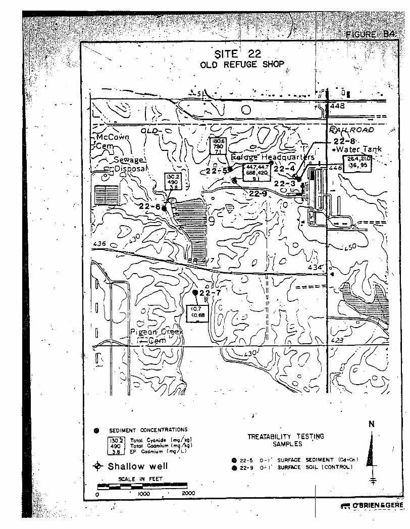
SEDIMENT CONCENTRATIONS
IsoT 490
Total Cyanide (mq/kg) Totol CodmKjm (mo Ag ) EP (xidmium ( m q / L )
^ Shallow well
SCALE IN FEET
1000
TREATABILITY TESTING SAMPLES
A 22-5 o - l ' SURFACE SEDIMENT (Cd-Cn) © 2 2 - 9 O - l ' SURFACE SOIL (CONTROL)
2000
Ii-j ;k«,;- '- ,- . • f i f ; O'BRIEN fi GERE

S>c;-: i i* . i^
FIGURE B5
SITE 32 AREA 9 LANDFILL
LEGEND
A LANDFILL BORINO , ' . J , GRID LOCATION
A SEDJiCWT BORING -^ IXCATKM ,
PCB (»NCCHTRATION Ing /kq WET Wl LEAD CONCENTRATION (mQAg OKf V»T
PCS L U D { f>am II R n m l y i l i ) » TOP CORE
WO CORE BOTTOM CORC
LOCATION WHERE LEAD , QONCENTHATION EXCEEDS
eACKonourro cotKCNTRUK)-
AT CONTROL SITES.
@ DCCONTAUINATDN AREA (S) VMSTE STORAGE AREA
V O T t ' I n * K " « f l i f h> S«>v(k« LaoMW>i
AfPBOXlMATE SCALE IN FEET •
150
@ ooniENCCEne
^ ^ ^ y f.V
1
. ' • '
"^jifyifc^iiii. yy$^':ym § 0 ^ y :'' '

g g f OBRIEJilCGEriE^^:.