objective of lecture - virginia techliab/analogue electronics/week 7... · objective of lecture ......
TRANSCRIPT

Objective of Lecture Introduce the superposition principle.
Provide step-by-step instructions to apply superposition when calculating voltages and currents in a circuit that contains two or more power sources.
Any combination of voltage and current sources.
Chapter 5.2
Basic Engineering Circuit Analysis by
J.D. Irwin and R.M. Nelms
Superposition The voltage across a component is the algebraic sum of
the voltage across the component due to each independent source acting upon it.
The current flowing through a component is the algebraic sum of the current flowing through component due to each independent source acting upon it.
Usage Separating the contributions of the DC and AC
independent sources.
Example:
To determine the performance of an amplifier, we calculate the DC voltages and currents to establish the bias point.
The AC signal is usually what will be amplified.
A generic amplifier has a constant DC operating point, but the AC signal’s amplitude and frequency will vary depending on the application.
Steps 1. Turn off all independent sources except one.
2. Redraw circuit.
3. Solve for the voltages and currents in the new circuit.
4. Turn off the active independent source and turn on one of the other independent sources.
5. Repeat Steps 2 and 3.
6. Continue until you have turned on each of the independent sources in the original circuit.
7. To find the total voltage across each component and the total current flowing, add the contributions from each of the voltages and currents found in Step 3.
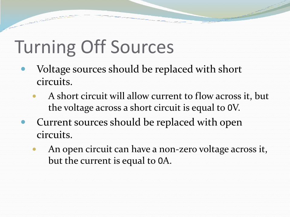
Turning Off Sources Voltage sources should be replaced with short
circuits.
A short circuit will allow current to flow across it, but the voltage across a short circuit is equal to 0V.
Current sources should be replaced with open circuits.
An open circuit can have a non-zero voltage across it, but the current is equal to 0A.
A Requirement for Superposition Once you select a direction for current to flow through
a component and the direction of the polarity (+ /_ signs) for the voltage across a component, you must use the same directions when calculating these values in all of the subsequent circuits.
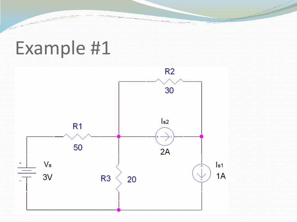
Example #1
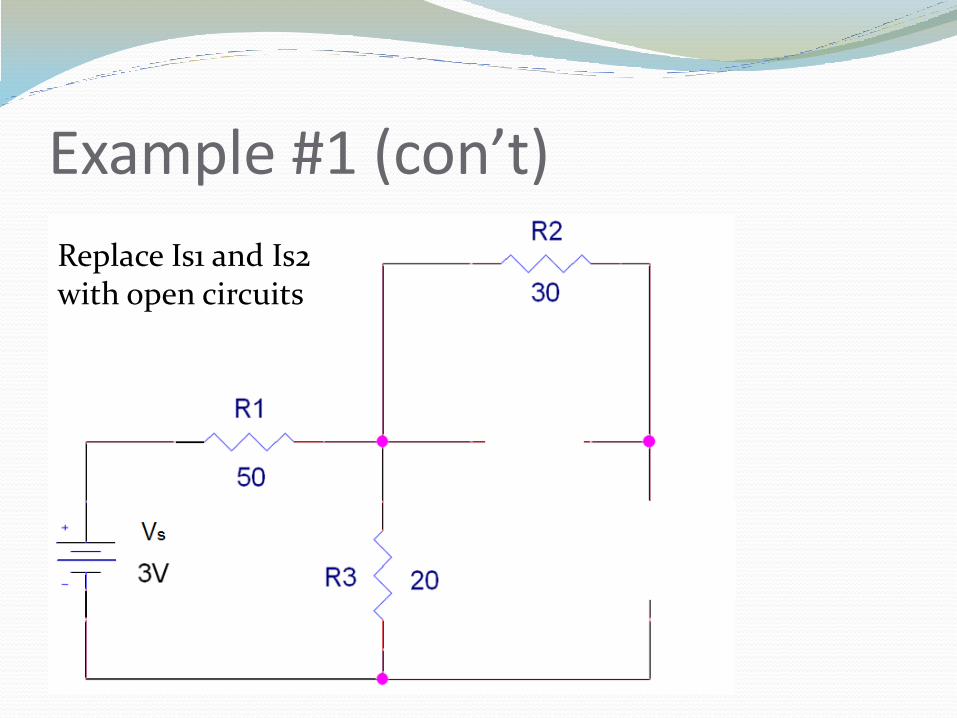
Example #1 (con’t)
Replace Is1 and Is2 with open circuits
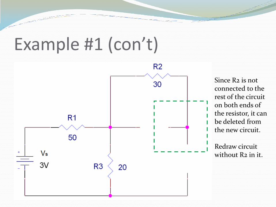
Example #1 (con’t)
Since R2 is not connected to the rest of the circuit on both ends of the resistor, it can be deleted from the new circuit. Redraw circuit without R2 in it.
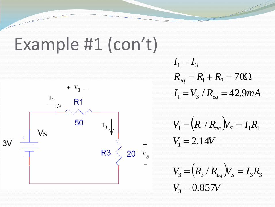
Example #1 (con’t)
Vs
VV
RIVRRV
VV
RIVRRV
mARVI
RRR
II
Seq
Seq
eqS
eq
857.0
/
14.2
/
9.42/
70
3
3333
1
1111
1
31
31
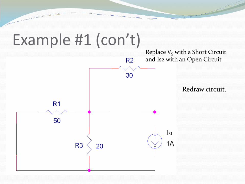
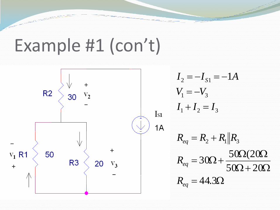
Example #1 (con’t) Replace VS with a Short Circuit and Is2 with an Open Circuit
IS1
Redraw circuit.
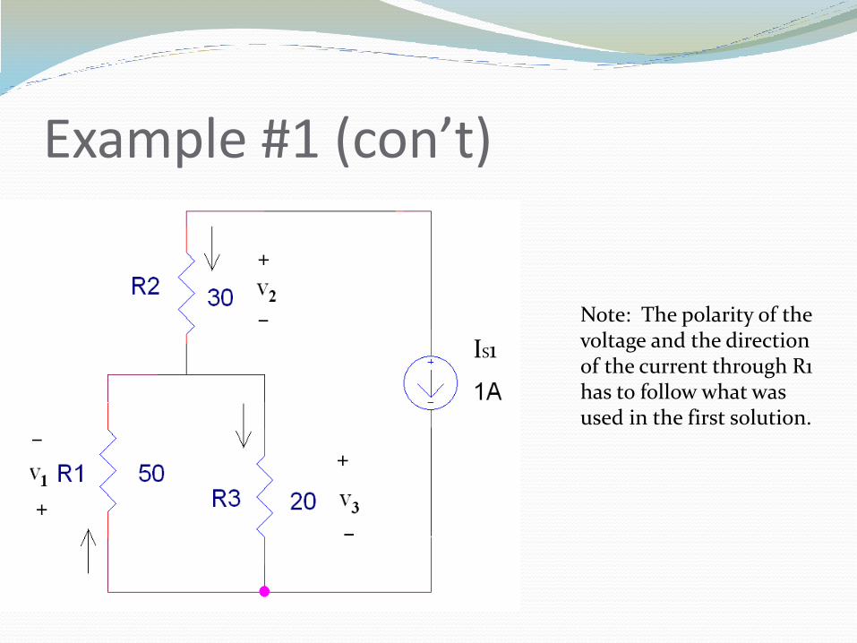
Example #1 (con’t)
Note: The polarity of the voltage and the direction of the current through R1 has to follow what was used in the first solution.
IS1
Example #1 (con’t)
IS1
3.44
2050
20(5030
1
312
321
31
12
eq
eq
eq
S
R
R
RRRR
III
VV
AII
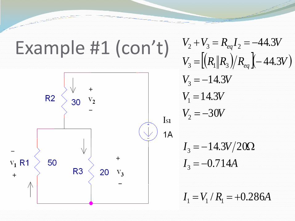
Example #1 (con’t)
IS1
ARVI
AI
VI
VV
VV
VV
VRRRV
VIRVV
eq
eq
286.0/
714.0
203.14
30
3.14
3.14
3.44
3.44
111
3
3
2
1
3
313
232
Example #1 (con’t)
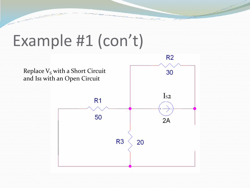
Replace VS with a Short Circuit and Is1 with an Open Circuit
IS2
Example #1 (con’t)
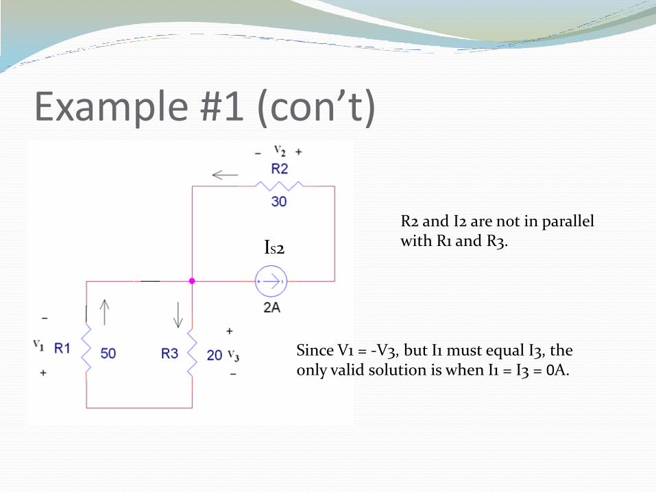
Since V1 = -V3, but I1 must equal I3, the only valid solution is when I1 = I3 = 0A.
R2 and I2 are not in parallel with R1 and R3. IS2
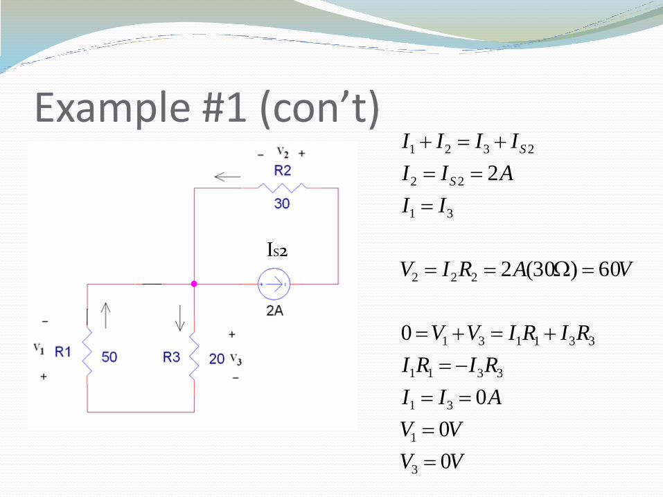
Example #1 (con’t)
IS2
VV
VV
AII
RIRI
RIRIVV
VARIV
II
AII
IIII
S
S
0
0
0
0
60)30(2
2
3
1
31
3311
331131
222
31
22
2321
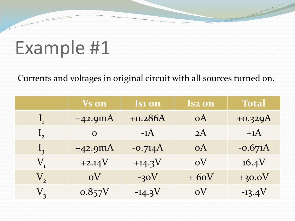
Example #1
Vs on Is1 on Is2 on Total
I1 +42.9mA +0.286A 0A +0.329A
I2 0 -1A 2A +1A
I3 +42.9mA -0.714A 0A -0.671A
V1 +2.14V +14.3V 0V 16.4V
V2 0V -30V + 60V +30.0V
V3 0.857V -14.3V 0V -13.4V
Currents and voltages in original circuit with all sources turned on.
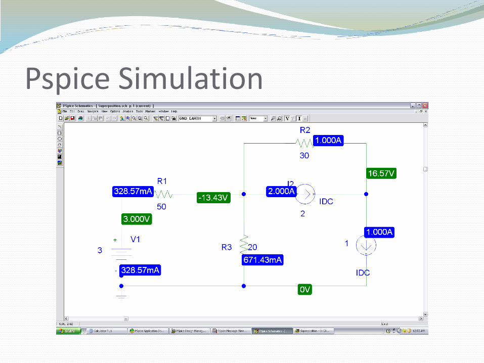
Pspice Simulation
Summary Superposition can be used to reduce the complexity of a
circuit so that the voltages and currents in the circuit can be determined easily.
To turn off a voltage source, replace it with a short circuit.
To turn off a current source, replace it with an open circuit.
Polarity of voltage across components and direction of currents through the components must be the same during each iteration through the circuit.
The total of the currents and voltages from each iteration is the solution when all power sources are active in the circuit.