‘o’ rings - inside - anasayfa walker/o-rings.pdf · selecting an ‘o’ ring this guide...
TRANSCRIPT

‘O’ Rings
High Performance Sealing Technology
The comprehensive guide to‘O’ ring sealing systems, including� ‘O’ ring selection� General & high performancematerials
� Housing design & tolerances� Kits, cords & accessories
Guide to ‘O’ rings
Introduction
The ‘O’ ring, or toroidal seal, is anexceptionally versatile sealing device.Applications ranging from garden hosecouplings to critical aerospace or refineryduties make it the world’s most popularvolume-produced seal.
‘O’ rings offer many benefits to designengineers and plant operators, they:
� Suit many static and dynamic duties.� Occupy little space.� Seal efficiently in both directions.� Are compatible with most fluid media.� Can work between –65°C and +315°C
when made of elastomer – accordingto material type.
� Can function at temperatures down to–200°C when made of PTFE.
Today, the design engineer is faced with abewildering array of ‘O’ ring statistics andadvice. In this guide we simplify designdata, give concise information onmaterials and facilitate part selection forspecification and ordering purposes.
The result is a document that containsvaluable information for use by buyers,designers and maintenance staff.
‘O’ ring stocks
We now stock over seven million ‘O’ ringsready for same-day despatch. If the ringsyou want are not available off-the-shelf,we can supply them within days from ourextensive manufacturing facility. With ourflexible production schedules, we canmeet the most urgent requests fromindustry.
Quality
Quality standardsOur quality systems are third-partyregistered to BS EN ISO 9001:2000. Weare also regularly assessed and qualityapproved by a wide range of industrybodies and individual customersincluding multinational corporations,utilities and government organisations.
In addition, we hold test equipment for allrelevant BS, ISO, ASA, API, ANSI, DIN,DTD and NATO standards. Certificates ofconformity are supplied on request.Packaging and labelling is available toindividual specifications.
Quality production and inspectionOur Materials Technology Centre housesone of Europe’s most advanced facilitiesfor elastomer batch production. At itsheart is a computer-controlled internalmixer that holds formulae for over 300 ofour elastomeric compounds.
Together with on-line rheometer testing,this gives us complete batch traceability,regardless of any release certificaterequirements.
The post-curing of silicone andfluorocarbon elastomers is also undermicroprocessor control for temperaturelevel and time. Each cure cycle is trace-recorded as a vital link in our quality chain.
Every ‘O’ ring we manufacture is visuallyinspected. This is backed by batchinspection of physical dimensions with aneven closer study of mismatch, flash andother specific parameters.
Material Safety Data Sheets (MSDS) areavailable on request.
Trademark acknowledgementsJames Walker acknowledges the following trademarks as mentioned in this guide.All other names bearing the ® symbol are registered trademarks of James Walker.
Trademark Company Trademark Company
Aflas® Asahi Glass PEEK™ Victrex plcDyneon™ 3M Dyneon Tecnoflon® Solvay SolexisHypalon® DuPont Performance Elastomers Viton® DuPont PerformanceKalrez® DuPont Performance Elastomers Elastomers
Contents
Introduction 2ʻOʼ ring stocks 2Quality 2Trademark acknowledgements 2
How to use this guide 3-5Selecting an ʻOʼ ring 3Selecting a back-up ring 3Selecting a material 4Coloured materials 4How to order 5
Materials & properties 6-10General materials 6Commercial ʻOʼ rings 6High performance materials 7Guide to material use 8Lubricants 8Surface texture 8Explosive decompression 9FEP encapsulated ʻOʼ rings 10Back-up rings 10
James Walker ʻOʼ rings 11-23Chart 50: Inch and metric sizes 11-17ʻOʼ rings for pipe fittings 17Chart 72: Metric sizes 18-20Chart 17000: Inch sizes 21-22Non-standard sizes 23
Design notes 24-28Design notes: General 24-25Design notes: Housings 26-28(fold out page 28 for easy reference)
ʻOʼ ring cord & kits 29ʻOʼ ring cord 29ʻOʼ ring kits 29Special packaging and kits 29
Distribution network 30
To order or get further details, call your local contact shown on rear cover or listed at www.jameswalker.biz2

To order or get further details, call your local contact shown on rear cover or listed at www.jameswalker.biz 3
How to use this guide
Selecting an ‘O’ ring
This guide contains three chart sizes:l Chart 50 – including BS 1806 and SAE
AS 568.l Chart 72 – metric sizes to BS 4518.l Chart 17000 – James Walker inch sizes.
To match an existing ‘O’ ringIf your existing ‘O’ ring has a BS 1806,SAE AS 568 or BS 4518 reference:
1. Refer to Chart 50 for BS 1806 and SAEAS 568, or Chart 72 for BS 4518.
2. Quote appropriate James Walkernumber.
Table 1: Diameter sections used in JWcharts
If only the size is known1. Obtain diameter section A of ‘O’ ring .
2. Consult Table 1 (above) to find the JWchart that covers rings of theappropriate diameter section A.
3. Consult appropriate JW chart, underspecific diameter section A.
4. Obtain inside diameter B of ‘O’ ring.
5. Refer to column on JW chart that listsinside diameters B and identify yourexisting ‘O’ ring.
6. Quote appropriate James Walkernumber.
If your ‘O’ ring is a non-standard sizeContact our Technical Services Team. Wehave in excess of 8000 ‘O’ ring mouldingtools in our library and are sure we canhelp.
Selecting a back-up ring
One or more back-up rings are used toprevent extrusion of an elastomeric ‘O’ring under arduous operating conditions.Our standard back-up rings are machinedin PTFE and normally supplied in singleturn or spiral form. See page 10 for moredetails of back-up rings.
Chart 50 Chart 72 Chart(BS 1806 & (BS 4518) 17000SAE AS 568A)0.070"/1.78mm 1.6mm 0.063"0.103"/2.62mm 2.4mm 0.094"0.139"/3.53mm 3.0mm 0.125"0.210"/5.33mm 5.7mm 0.188"0.275"/6.99mm 8.4mm 0.250"
A
B
For an existing housing1. Refer to diagrams on page 28.
2. Select the one that matches yourhousing.
3. Obtain from existing housing the criticaldimensions shown on selected diagram.
4. Refer to Housing Tables 7 & 8 on page26. These show BS1806/SAE AS 568 inboth inch and metric units, and BS 4518(metric) with more data on pages 18-20.
5. Cross reference dimensions on housingtables.
6. Read off diameter section A, andconsult appropriate JW chart under thatspecific diameter section.
7. Refer to column that shows housingdiameter (coded as selected diagramon page 28) and identify the one thatmatches yours.
8. Quote appropriate James Walkernumber.
For a new application1. Refer to Design notes section, pages
24-28, for guidance with regard toapplications.
2. For metric equipment, select ‘O’ ringfrom Chart 72, pages 18-20.
3. If the metric size you require is notavailable from Chart 72, then selectfrom metric columns in Chart 50, pages11-17.
4. For inch sizes use Chart 50, or Chart17000 on pages 21-22.
Back-up ring for use with James Walker‘O’ ring numberRefer to How to order section on page 5for precise specification details relating toback-up rings for Chart 50, Chart 72 andChart 17000 applications.
Back-up ring for use with existing‘O’ ring1. Identify appropriate JW chart and
James Walker number for existing ‘O’ring. If necessary, use method outlinedon this page in To match an existing ‘O’ring. (NNoottee: If a standard ‘O’ ring hasbeen used on a non-standard shaft orcylinder – ie, compressed or stretchedinto place – the equivalent standardback-up ring must not be used as itcannot be stretched or squeezed in thesame way.)
2. Refer to How to order section on page 5for precise specification details.
Back-up ring for use with non-standardsize ‘O’ ringContact our Technical Service Team whowill recommend the correct back-up ring.
Back-up ring for new application1. Select the ‘O’ ring you require from JW
charts, using method outlined on thispage.
2. Refer to How to order section on page 5for precise specification details.
Figure 1: ‘O’ ring diameter section A andinside diameter B

To order or get further details, call your local contact shown on rear cover or listed at www.jameswalker.biz4
How to use this guide
Selecting a material
Table 2 gives details of our nine mostwidely demanded stocked materials. Werecommend that you specify one of thesewherever possible for your ‘O’ rings. Fulldetails of all readily available materials andtheir chemical compatibility are given onpages 6-8.
We generally stock compounds of 80IRHD (International Rubber HardnessDegrees) as these:
l Frequently give extrusion resistanceapproaching that of 90 IRHD.
l Give sealability comparable to materialsof 70 IRHD.
‘O’ ring sizes shown on Chart 50, Chart72 and Chart 17000 are supplied fromstandard low or high shrinkage toolingwithout mould charges. Our highshrinkage tooling allows fluorocarbon andsilicone ‘O’ rings to be manufacturedwithin the tolerances shown on page 23.
If you have any doubt about materialselection, please consult our TechnicalServices Team for specificrecommendations.
Coloured materials
Quality management systems, productliability and health and safety issues havecreated a growing need to identifyelastomers by their colour. With stocks ofblack components held in severalmaterials, it is possible for the end user toselect the wrong item and cause anequipment malfunction.
Common mistakes include using nitrileNBR seals in phosphate-ester hydraulicfluid systems or ethylene-propylene EPMrubber with mineral oil. To help overcomethis, we offer the following non-blackcompounds:
l Fluorocarbon (FKM) – green.l Silicone (VMQ) – white or red.l Ethylene-propylene (EPM) – red.
It should be noted that physical propertiesmay vary from standard materials, alsothat other colours may be available.Please consult our Technical ServicesTeam for specific recommendations.
Standardcompound Rubber type Specifications Stocked Colour ASTM D2000 referencereference
PB80 Medium nitrile ASTM D2000 M2BG 810, B14, EF11, EF21, EO14, EO34(NBR)
*BS6996 Grade BO80 3 BlackBS 5176 2MBG 810, B14, E14, E34, E51, E61
EP18/H/75 Ethylene-propylene ASTM D2000 M3BA 810, A14, B13, Z1(EPM) 3 Black
Z1: Hardness 75±5 IRHD
FR10/80 Fluorocarbon (FKM) **DTD 5612A Grade 80 3 Black ASTM D2000 M6HK 810, A1-10, B36
FR25/90 Fluorocarbon (FKM) 3 Black ASTM D2000 M7 HK 914, B38, Z1**
FR58/90 Fluorocarbon (FKM) 3 Black ASTM D2000 M3HK 910, A1-10, B38, Z1**
Elast-O-Lion® 101 Hydrogenate nitrile(HNBR)
3 Black
Elast-O-Lion® 180 Hydrogenated nitrile(HNBR) 3 Black
Elast-O-Lion® 985 Hydrogenated nitrile(HNBR)
3 Black
SIL 80/2 Silicone (VMQ) *DTD 5582A Grade 80 ASTM D2000 7GE 805, A19, B37, EO36, Z1(as amended)
WhiteZ1: colour white
(Due to be supeseded3
BS 5176 2MGE 805 A19, B17, Z1by BS F153) Z1: colour white
* All DTD specifications have been declared OBSOLESCENT.** Suitable for explosive decompression, consult our Technical Services Team.* Note: Please specify on your enquiry or order if you want ‘O’ rings to meet these specifications.
Table 2: Stocked material details

To order or get further details, call your local contact shown on rear cover or listed at www.jameswalker.biz 5
How to use this guide
How to order
The following information and exampleswill enable you to order the correct ‘O’ ringand back-up ring to meet specificrequirements.
For particularly critical applications –including those requiring FEPencapsulated ‘O’ rings – we recommendthat you state the following details toenable us to ensure suitability:
l Pressures.l Pressure media.l Operating temperatures.l Static or dynamic operation (with
speeds, if appropriate).l Housing type.l Tolerances.l Any other important factors.
‘O’ ringsSSttaannddaarrdd ssiizzeess For a standard size ‘O’ring, listed on our charts, please stateappropriate James Walker numberfollowed by materials reference. II ff nnoommaatteerriiaall oorr aapppplliiccaattiioonn ccoonnddiitt iioonnssaarree ssppeecciiffiieedd wwee wwiill ll ssuuppppllyy oouurrmmeeddiiuumm nniittrriillee ggrraaddee PPBB8800..
EXAMPLE: JW 50-001 PB80
OOtthheerr ssiizzeess For other sizes, please stateinside diameter, diameter section andmaterial reference.
EXAMPLE: ID 49.4mm, DS 4.1mm.SIL 80/2
Back-up ringsBack-up rings are supplied in spiral formunless single turn is stated. Also, they aresupplied in PTFE as standard, unlessotherwise stated.
BBaacckk--uupp rriinnggss –– CChhaarrtt 5500,, iinncchhssiizzeessWhen ordering Chart 50 back-up rings forinch size shafts and cylinders, please statethe same JW50 number as for the ‘O’ ring.Also indicate spiral or single turn, andmaterial.
EXAMPLE: For a JW 50-433 (0.275inch diameter section) ‘O’ ring on a5⁄÷™ inch diameter shaft or 6 inchdiameter cylinder, order JW 50-433
PTFE spiral back-up ring. BBaacckk--uupp rriinnggss –– CChhaarrtt 5500,, mmeettrriiccssiizzeessWhen ordering Chart 50 back-up rings tomatch our suggested metric shaft andcylinder sizes, please use:
l Prefix 150 for shaft applications.l Prefix 250 for cylinder applications.
The reason is that ‘O’ rings can bestretched or squeezed by a smallpercentage – see Design notes pages 24-

To order or get further details, call your local contact shown on rear cover or listed at www.jameswalker.biz6
Materials & properties
General materials
Note: Materials for stocked ‘O’ rings areprinted in red. For specific details seeSelecting a material on page 4.
Nitrile – acrylonitrile-butadiene (NBR)Stocked grade PB80We have a wide range of compoundsbased on various acrylonitrile/butadieneratios. Higher acrylonitrile contentgenerally gives better hydrocarbonresistance, whereas low acrylonitrilecontent gives better low temperatureflexibility. Our PB range is suitable for usewith mineral oils – particularly hydraulictypes – as well as water and somesolvents. Our Proteus range is generallysuitable for food applications, but pleaseconsult our Technical Services Team onspecific applications before ordering.
Chloroprene (CR) – eegg,, NNeeoopprreenneeThese general purpose rubbers are largelyunaffected by sunlight and atmosphericaging. They will give satisfactory service inmany media, such as mineral lubricatingoils and greases, dilute acids/alkalis andsome solvents.
Natural rubber (NR)Materials based on natural rubber havehigh strength and high resilience with goodabrasion resistance. They are suitable foruse in hot and cold water, ammonia,ethylene glycol, dilute acids and alkalis.Limited resistance to heat, weathering andoils has reduced the use of natural rubbersin favour of synthetic elastomers.
Ethylene-propylene (EPM/EPDM) Stocked grade EP18/H/75These compounds have excellentresistance to weathering, ozone, hot andcold water and steam. EPM grades areavailable for use with water up to +180°C,making them ideal for steam raising plant.These materials also display resistance toaliphatic phosphate-ester hydraulic fluids,acids, alkalis, salt solutions, alcohols,glycols and silicone oils.
Our EP62 range of rubbers for potablewater applications is WRAS approved.
Butyl – isobutylene-isoprene (IIR)Butyl rubber has similar chemicalresistance to ethylene-propylene. Very lowgas permeability makes butyl popular forvacuum and high pressure gasapplications. It must nnoott be used withmineral oils.
Epichlorhydrin (ECO)Compounds based on this elastomerhave good resistance to mineral oils,fuels and ozone. Corrosive properties andpoor compression set resistance limit theuse of these materials for sealingapplications.
Chlorosulphonated polyethylene (CSM)– eegg,, HHyyppaalloonn®®
These elastomers show excellentresistance to weathering and give goodservice in many media. They are notrecommended for dynamic sealapplications as compression setresistance is limited.
Polyurethane (AU/EU)Stress relaxation at above +50°C oftenprecludes these elastomers from ‘O’ ringsealing applications. However, manypolyurethane ‘O’ rings are used in drivetransmissions where their tensile strength,elongation characteristics and wearresistance prove invaluable. Thesematerials also have excellent resistance toweathering and oxygen, and goodresistance to hydrocarbon fuels andmineral oils. Resistance to acids is low,and some grades are affected by waterand humidity.
Fluorosilicone (FVMQ, FMQ)Fluorosilicone grades are available forapplications involving hydrocarbon oils,petroleum fuels and mineral-basedhydraulic fluids. This material is primarilyused for static seals in aerospace fuelsystems. It has similar mechanicallimitations to silicone.
Silicone (VMQ)Stocked grade SIL 80/2Many grades of silicone rubber areavailable. They offer good resistance toweathering and compression set at hightemperatures, plus excellent electricalproperties. Use is limited by high gaspermeability, low tensile strength, andpoor resistance to tear and abrasion.Some grades are suitable for foodapplications.
Commercial ‘O’ rings
To complement our premium products, wesupply general purpose ‘commercialquality’ ‘O’ rings for less criticalapplications. These are available with:l Competitive prices.l Full traceability – on request.l Quantities from one to millions.l Wide range of material and sizes.
Materials – a comprehensive rangeincluding:l Ethylene-propylene (EPM/EPDM)l Neoprene (CR)l Nitrile (NBR)l Polyurethane (AU/EU)
l Silicone (VMQ)l Fluoroelastomer (FKM)
Commercial ‘O’ rings are supplied toJames Walker Charts:l JW46: covering BS 1806 & SAE AS 568.l JW47: European metric range. l JW48: metric sizes to BS 4518. l JW49: Japanese industry sizes.
Non-standard sizes are also available incommercial materials to suit specificcustomer requirements.
Please contact our Technical ServicesTeam to determine product suitability.

To order or get further details, call your local contact shown on rear cover or listed at www.jameswalker.biz 7
Materials & properties
Fluolion® (PTFE)Fluolion® is the registered trademark ofJames Walker products manufacturedfrom polytetrafluoroethylene. PTFE is anextremely inert material, unaffected byvirtually every known chemical includingmost acids, alkalis and solvents. Theseexceptional properties make PTFE theideal material for ‘O’ ring back-up rings.
The flow characteristics of PTFE understress are usually a disadvantage in ‘O’rings.
Elast-O-Lion® – hydrogenated nitrile(HNBR)Stocked grades Elast-O-Lion® 101, 180,985Elast-O-Lion® is the registered trademarkof James Walker for its range of highperformance hydrogenated nitrilecompounds.
These materials have the excellentoil/fuel resistance of traditional nitrile(NBR) elastomers. They also havesuperior mechanical properties and cansustain higher service temperatures: eg,up to +180°C in oil. In addition, theydisplay superior resistance to aggressivefluids such as sour (H2S) crude oil,lubricating oil additives and aminecorrosion inhibitors. Fully saturatedgrades of HNBR have excellent resistanceto ozone.
Five ranges are available with variousacrylonitrile contents from low to ultrahigh, and hardnesses of 50 to 90 IRHD. Inaddition, four grades – Elast-O-Lion 101,201, 301 and 985 – have been speciallydeveloped for oilfield duties where acombination of high mechanical strength,resistance to explosive decompression(ED) and chemical resistance is required.
Temperature capability is between –46°Cand +180°C depending on material gradeand application.
Further information on elastomersFor additional information on ourextensive range of high performanceelastomers, please refer to our HighPerformance Elastomers guide.
High performance materials
Fluoroelastomers (FKM) –– eegg,, VViittoonn®®,,TTeeccnnoofflloonn®®,, DDyynneeoonn™™ Stocked grades FR10/80, FR25/90,FR58/90Fluoroelastomers operate efficiently undersevere chemical conditions and at highertemperatures where many other sealmaterials cannot survive. According tograde they are well suited to arduousapplications involving:
l Temperatures from –30°C to +250°C.l Petroleum fuels and mineral-based
hydraulic fluids.l Many solvents.
We have developed numerous grades offluoroelastomer, including the following:
GGeenneerraall ppuurrppoossee fflluuoorrooeellaassttoommeerrssFR10: Dipolymer-based range withhardnesses of 50 to 90 IRHD. Thesegrades are ideal for general applicationsand are approved to UK Ministry ofDefence low compression setspecifications.
FR17: Terpolymer-based range withhardnesses of 65 to 95 IRHD. It hasenhanced chemical resistance and betterhigh temperature flexibility characteristicsthan FR10, although these properties are –to some extent – at the expense ofcompression set resistance.
FR44: Dipolymer-based range withhardnesses of 50 to 90 IRHD. It comes in adistinctive shade of green for easyidentification. These low compression setgrades meet many regularly usedspecifications.
SSppeecciiaall ff lluuoorrooeellaassttoommeerr ggrraaddeessMany grades are available for specificduties. The following are of particularvalue:
FR58/90 & 98: These terpolymer-basedgrades resist explosive decompression(ED) as described on page 9, and havegood all round elastomeric properties.We are market leader in seals for EDenvironments.
FR64/70 & 80: Dipolymer-basedcompounds developed to offer enhancedperformance in steam, hot water andmineral acids.
LR5853: Tetrapolymer-based range withhardnesses of 80, 90 and 98 IRHD. It hasenhanced fluid resistance, especially withmethanol and gasoline-alcohol blendsthat adversely affect otherfluoroelastomers. These grades stiffenbelow –5°C, thus LR6316 and FR25 arerecommended for low temperature use.
LR6316: Available in hardnesses of 75 and90 IRHD, these compounds are based ona special tetrapolymer with a similar fluidresistance to LR5853, plus improved lowtemperature characteristics for servicedown to –28°C.
FR25: Tetrapolymer-based range withhardnesses of 70 to 90 IRHD. Offers fluidresistance approaching that of the FR10range plus improved low temperaturecharacteristics for service down to –33°C.FR25/90 is compounded for explosivedecompression (ED) resistance.
Aflas® (FEPM) These compounds have resistance to oils,lubricants and some fuels approachingthat of fluorocarbon dipolymers but, inaddition, are suitable for sour gas dutiesor where amines and high temperaturewater or steam are used.
AF85: Available in hardnesses of 70, 80and 90 IRHD. Typical maximum servicetemperature is +200°C although highertemperatures can be sustained in somemedia: eg, up to +260°C in steam. Otherspecialised grades are available, such asAF69/90 that is compounded for explosivedecompression (ED) resistance.
Kalrez® – perfluoroelastomer (FFKM)These perfluoroelastomers offer almostuniversal chemical resistance. Grades areavailable for continuous operation at up to+315°C. James Walker is authorised UKdistributor for Kalrez® products used forfluid sealing and handling duties. Pleaseask for technical details and separateliterature.

To order or get further details, call your local contact shown on rear cover or listed at www.jameswalker.biz8
Materials and properties
Lubricants
We recommend the following lubricantsbe specified and applied lightly to ‘O’ ringsbefore assembly (but please note theimportant eexxcceeppttiioonnss):
l James Walker’s Molyon Grease,containing MoS2, for operatingtemperatures from –20°C to +150°C.
l James Walker’s Silicone Grease, foroperating temperatures from –50°C to+200°C.
l James Walker’s Copper Anti-SeizeCompound or Nickel Anti-SeizeCompound for operating temperaturesabove +200°C.
EExxcceeppttiioonnss: DO NOT use mineral-basedoil or grease, such as our Molyon andAnti-Seize Compounds, on seals madefrom natural rubber (NR), butyl (IIR) orethylene-propylene (EPM/EPDM).Likewise, DO NOT use silicone oil orgrease on seals made from silicone (VMQ)compounds.
Surface texture
All ‘O’ rings precision-moulded by JamesWalker are supplied with surface texture toGrade N of BS ISO 3601-3 Limits ofsurface imperfections on elastomerictoroidal sealing rings (‘O’ rings), with thehigher Grade S provided if required.
Our Commercial ‘O’ rings (page 6) anditems in our ‘O’ Ring Kits (page 29) do notnecessarily comply with Grade N surfacetexture. Please consult our TechnicalServices Team if surface texture isimportant for your specific application.
Guide to material use
Acrylic ACM 2 4 4 4 4 4 4 4 3 3 4 1 3 1 1 1 1 1 2 1 1 1 4 4 4 4 4 4 –20 150 175 80Aflas® FEPM 1 1 1F 1 2 1 1 1 1 4 4 1 3 2 1 1 1 1 2 1 1 1 2 1 1 1 1 2 0 200 230F 70 - 90Butyl IIR 1 1 2 1 1 1 1 2 4 4 1 4 4 4 4 2 4 4 4 1 3 4 4 4 4 1 2 2 –35 120 150 60 - 70 BS 3227Elast-O-Lion® HNBR 1 1 1 1 2 1 2 1 2 4 4 1 3 2 1 1 2 1 1 1 1 1 4 2 2 2 1 4 –25A 160 200 50 - 90Epichlorohydrin ECO 2 2 3 3 2 2 4 4 4 4 4 3 4 1 1 1 1 1 4 1 1 1 4 2 2 2 4 4 –30 150 175 70 - 90Ethylene-propylene EPM/EPDM 1 1 1 2 1 1 1 2 4 3 1 4 4 4 4 2 4 4 4 1 3 4 4 4 4 1 1 2 –45 120 150B 50 - 90 *DTD 5597, 5608Fluolion® PTFE 1 1 1 1 1 1 1 1 1 1 1 1 1 1 1 1 1 1 1 1 1 1 1 1 1 1 1 1 –200 250Fluoroelastomers FKM 1 1 3 1 2 4C 4C 4C 1 3C 4C 1 1 1 1 1 1 1 2 1 1 1 2 1 1 2 3 1 –15D 200 230D 50 - 98 DEF STAN 02-337,
*DTD 5543, 5603, 5612, 5613.Fluorosilicone FVMQ 1 1 2 3 2 1 4 4 1 3 4 1 1 2 1 1 2 1 2 3 1 2 4 2 2 2 3 3 –60 180 200 60 - 80 *DTD 5583Hypalon® CSM 2 1 3 4 1 1 3 4 4 4 4 2 4 4 4 3 3 4 4 1 2 2 4 4 3 1 4 4 –30 120 150 65 - 80Kalrez® FFKM 1 1 1 1 1 1 1 1 1 1 1 1 1 1 1 1 1 1 1 1 1 1 1 1 1 1 1 1 –25 315 350 65 - 95 SAE AMS 7257Natural rubber NR 3 2 4 3 2 2 3 2 4 4 4 4 4 4 4 4 4 4 4 1 4 4 4 4 4 3 4 4 –50 100 120 40 - 85 BS 1154, DEF STAN 02-820 &
*DEF STAN 22-005Neoprene CR 1 2 3 3 2 1 3 2 4 4 4 2 4 3 2 2 3 2 3 1 3 3 4 4 4 3 4 4 –40 120 150 40 - 90 BS 2752Nitrile NBR 2 1 3 3 2 1 3 4 3 4 4 1 3 2 1 1 2 1 2 1 1 1 4 3 3 1 4 4 –30A 120 150 40 - 90 BS 2751, 6996, 6997, DEF
STAN 02-337, *DEF STAN 22-005,*DTD 5509, 5594, 5595, 5606, 5607.
Polyurethane AU/EU 1 4 4 4 4 4 4 4 3 2 4 2 4 2 2 2 3 2 4 1 2 1 4 4 4 4 4 4 –15 85 100 55 - 95E
Silicone VMQ 1 1 1 3 2 1 2 2 4 4 3 3 4 4 4 2 4 3 3 4 1 4 3 3 4 2 3 3 –60 200 250 40 - 80 *DTD 818, 5531, 5582, 5605
MAT
ERIA
LTY
PE
Air o
r oxy
gen
Wat
er –
up
to 8
0°C
Wat
er –
abo
ve 8
0°C
Dilu
te a
cids
Dilu
te a
lkal
isLo
wer a
lcoh
ols
Alde
hyde
sAm
ines
Chlo
rinat
ed s
olve
nts
Ethe
rsKe
tone
sHyd
roca
bron
s –
alip
hatic
Hydro
carb
ons
– ar
omat
ic
Lead
ed p
etro
l (ga
solin
e)
Kero
sene
Anim
al o
ils a
nd fa
ts
Fuel
oils
and
die
sel o
ils
Lubr
icat
ing
oils
– m
iner
al
Lubr
icat
ing
oils
– sy
nthe
tic
Silic
one
oils
and
grea
se
Vege
tabl
e oi
ls
Hydra
ulic
flui
ds –
min
eral
bas
ed
Chlo
rinat
edO
il in
water
em
ulsio
ns
Wat
er in
oil e
mul
sions
Wat
er –
gly
col b
ased
Phos
phat
e es
ters
– a
lipha
tic
Phos
phat
e es
ters
– a
rom
atic
Low
High
– co
ntin
uous
High
– in
term
itten
tHar
dnes
s ra
nge
IRHD
Avai
labl
e to
the
late
st is
sue
of
the
follo
wing
spec
ificat
ions
Temperaturerange (°C)
Hydraulic fluidsfire resistent
Key *These specifications have been declared OBSOLESCENT. Some DTD specifications are due to be superseded by BS F specifications.
1 Very Good ALow acrylonitrile content grades are available for temperatures down to –46°C2 Good BEPM grades are available for hot water service up to +180°C3 Fair CFluoroelastomer grades are available which offer resistance to these chemicals4 Not Recommended DFluoroelastomer grades are available for temperatures from –33°C to +250°C
EPolyurethane grades are also available from 60 to 74 hardness Shore DFAflas® grades suitable for temperatures up to +260°C in hot water and steam
NNoottee:: These figures are provided as a guide only. Actual service life will depend on type of application, whether static or dynamic,specific pressure medium, temperature cycle, time of exposure, etc. The low temperatures quoted are values at atmospheric pressureand may change at elevated pressures.
Table 3

To order or get further details, call your local contact shown on rear cover or listed at www.jameswalker.biz 9
Materials and properties
Explosive decompression damage isstructural failure in the forms of blistering,internal cracking and splits caused when thegas pressure, to which the seal is exposed,is rapidly reduced from high to low.
The elastomeric components of a systemare, to a greater or lesser extent, susceptibleto the permeation and diffusion of gasesdissolving in their surface. With time, thesecomponents will become saturated withwhatever gases are in the system.
Under these conditions – as long as theinternal gas pressure of the elastomerremains at equilibrium with the ambientpressure – there is minimal damage, if any,and no deterioration in performance of theelastomeric component occurs (unlesscaused by other factors such as chemicalor thermal degradation or by extrusiondamage).
When the external gas pressure is removedor pressure fluctuations occur, largepressure gradients are created between theinterior and the surface of the elastomericcomponent. This pressure differential maybe balanced by the gas simply diffusing/permeating out of the elastomer, especiallyif any external constraints are not removed.
However, if the physical properties of theelastomeric compound cannot resistcrack and blister growth during thepermeation process, then structural failureis the inevitable result.
Explosive decompression damage canmanifest itself in various ways – anythingfrom internal splits that are not visible onthe surface of the seal to surface blisters,fractures and complete fragmentation. ‘O’ rings after explosive decompression.
In order to overcome many of theproblems associated with high pressuregas systems, we have conductedintensive materials developmentprogrammes over the last 20 years. Muchof this work was carried out incollaboration with equipmentmanufacturers, major oil and gasoperators, and research bodies.
We offer five standard grades of EDresistant elastomer, all of which have beenextensively validated in-house.They aretested, approved and specified by oilfieldoperators and equipment manufacturersalike.
The formulation, mixing, quality control andprocessing of these compounds isrigorously controlled and today they arerated by many as the benchmarks by whichall others are judged. Although each ofthese compounds has a broad range ofapplication capability, their particularfeatures are as follows:
l FR58/90 – A fluoroelastomer (FKM) withexcellent chemical and thermalproperties, plus ED resistance inhydrocarbon applications. It is approvedand specified by many oil producersand equipment manufacturers.
l FR25/90 – This fluoroelastomer (FKM)combines an improved low temperaturecapability with excellent thermal andchemical properties. It is ED resistant inhydrocarbon applications.
l Elast-O-Lion 101 – An hydrogenatednitrile (HNBR) grade with highmechanical strength and wear resistantproperties. It has good resistance tomany oilfield chemicals including H2Sand amine corrosion inhibitors. It isresistant to explosive decompressionand is approved to many EDspecifications.
l Elast-O-Lion 985 – This hydrogenatednitrile (HNBR) grade offers improved lowtemperature capacity, but with reducedmechanical properties and ED resistancecompared to Elast-O-Lion 101.
l AF69/90 – An Aflas® (FEPM) based EDresistant grade with excellent resistanceto oilfield media and steam.
James Walker’s eight-flange explosive decompression test rigs.
Explosive decompression
Although explosive decompression (ED) isa phenomenon generally found in the oiland gas industry, it can be experienced inany application where there is a rapid dropin gas pressure.
ED damage has been noted in sealingapplications ranging from paint guns andfire extinguishers to marine stern glandseals and systems containing refrigerants.

To order or get further details, call your local contact shown on rear cover or listed at www.jameswalker.biz10
Materials and properties
FEP encapsulated ‘O’ rings
FEP encapsulated ‘O’ rings have a core ofelastomer that is completely covered witha seamless sheath of FEP fluoropolymer.The elastomeric core is normally eitherfluorocarbon or silicone.
An encapsulated ‘O’ ring is generally usedwhen:
l A standard elastomer ‘O’ ring hasinadequate chemical resistance for aparticular application, and
l A solid PTFE ‘O’ ring does not offersufficient elasticity for reliable, long-term fluid sealing.
They are typically used in the chemical,petrochemical, food and pharmaceuticalindustries and other sectors where high
levels of chemical resistance and/orhygiene are required.
Although FEP encapsulated ‘O’ rings aremost suited to static duties, they may beused with slow, short movements on rotaryapplications such as valve stem sealing.
Their advantages are manifold, including:
l Excellent chemical resistance to a widerange of media – please consult ourTechnical Services Team for furtheradvice.
l Operational temperature ranges of–60°C to +200°C with silicone core,–20°C to +200°C with fluorocarbon core.
l Low friction and low ‘stick-slip’ effect.l Can be used with food, pharmaceutical
and medical products.l Far better elasticity than solid PTFE.
Our FEP encapsulated ‘O’ rings are fullyinterchangeable with standard elastomeric‘O’ rings. However, due to the FEP sheath,they are less flexible than normalelastomeric ‘O’ rings and have limitedstretch with higher permanentdeformation. Auxiliary tools may beneeded to facilitate efficient fitting.
Back-up rings
Back-up rings are installed to preventextrusion of the ‘O’ ring. These aremanufactured from PTFE, PEEK™, andfilled PTFE.
They are normally recommended forapplications where:
l Pressure of the fluid medium exceeds100bar, or
l ‘O’ rings of low strength elastomer areused, or
l Adverse mechanical conditionsprevail.
Please consult our Technical ServicesTeam if fluid pressure is likely to exceed420bar.
Two back-up rings – one either side of the‘O’ ring in its housing – are needed whenthe application is double acting.
Back-up rings are normally supplied asa spiral of two turns. This enables theback-up ring to be opened with ease forfitting over a shaft, and ensures the ‘O’ring is supported around its entirediameter.
Single turn back-up rings can also besupplied and these are usually endless to
ensure good support. However, they canbe scarf split if required, although we donot recommend this because extrusioncan occur at the split.
Smaller sizes of back-up ring are availableonly as a single turn. This is because spiralback-up rings need an inside diametergreater than 3mm for machining purposes.
Groovelength1 back-up
Direction of pressure
Groovelength2 back-ups
Pressurefromeitherdirection
Groovelength1 back-up
Direction of pressure
Groovelength2 back-ups
Pressurefromeitherdirection
Groovelength1 back-up
Direction of pressure
Groovelength2 back-ups
Pressurefromeitherdirection
Groovelength1 back-up
Direction of pressure
Groovelength2 back-ups
Pressurefromeitherdirection
Groovelength1 back-up
Direction of pressure
Groovelength2 back-ups
Pressurefromeitherdirection
Groovelength1 back-up
Direction of pressure
Groovelength2 back-ups
Pressurefromeitherdirection
Figure 2: Typicalback-up ringinstallations
Figure 3: Spiralback-up ring
Figure 4:Typical housings
(see pages 24-28)

To order or get further details, call your local contact shown on rear cover or listed at www.jameswalker.biz 11
Chart 50: Inch and metric sizes
To order your Chart 50 ‘O’ ring or back-up ring, see page 5.
For housing details refer to pages 24-28.
Our Chart 50 reflects the standards in many countries,particularly those of the UK and USA. Despite UK metrification,inch sizes to BS 1806 are still very popular.
Reference numbers highlighted in red indicate those sizescovered by:
l BS 1806: Dimensions of toroidal sealing rings (‘O’ rings) andtheir housings (inch sizes), and
l SAE AS 568: American National Standard Aerospace sizestandard for ‘O’ rings.
Although the basic range is in inches, the ‘O’ rings can of coursebe used for sealing metric dimensioned components. The tablesbelow include suggested metric shaft and cylinder sizes forwhich each individual ‘O’ ring is suitable. (Note: These figures areNOT merely direct metric conversions of inch sizes. Separateranges of back-up rings are available for metric shafts andcylinders – see page 5 for ordering references.)
* An asterisk symbol denotes that the ring is suitable for bothdynamic and static applications. Other sizes are notrecommended for dynamic duties.
A
B
James INCH DIAMETERS METRIC DIAMETERS (mm)Walker Inside Inside Shaft Cyl.Number Dia. B C, P, T D, Q Dia. B C D
0.040 ±0.003” (1.02 ±0.08mm) Diameter Section A50-001 0.029 ±0.004 1/32 3/32 0.74 ±0.10 0.8 2.5
" 606 0.070 ±0.005 5/64 9/64 1.78 ±0.13 2 3.6" 607 0.100 " 7/64 11/64 2.54 " 2.8 4.5
0.050 ±0.003” (1.27 ±0.08mm) Diameter Section A50-002 0.042 ±0.004 3/64 0.130 1.07 ±0.10 1.2 3.3
0.060 ±0.003” (1.52 ±0.08mm) Diameter Section A50-003 0.056 ±0.004 1/16 11/64 1.42 ±0.10 1.5 4.1
0.070 ±0.003” (1.78 ±0.08mm) Diameter Section A50-004* 0.070 ±0.005 5/64 13/64 1.78 ±0.13 2 5
" 005* 0.101 " 7/64 15/64 2.57 " 2.8 6" 006* 0.114 " 1/8 1/4 2.90 " 3 6.2" 801* 0.125 " 9/64 17/64 3.18 " 3.5 6.5" 007* 0.145 " 5/32 9/32 3.68 " 4 7
James INCH DIAMETERS METRIC DIAMETERS (mm)Walker Inside Inside Shaft Cyl.Number Dia. B C, P, T D, Q Dia. B C D
0.070 ±0.003” (1.78 ±0.08mm) Diameter Section A50-008* 0.176 ±0.005 3/16 5/16 4.47 ±0.13 4.5 8
" 802* 0.188 " 13/64 21/64 4.76 " 5 8.5" 009* 0.208 " 7/32 11/32 5.28 " 5.5 9" 010* 0.239 " 1/4 3/8 6.07 " 6 9.5" 803* 0.250 " 17/64 25/64 6.35 " 6.5 9.8
" 610* 0.266 " 9/32 13/32 6.75 " 7 10" 011* 0.301 " 5/16 7/16 7.65 " 7.5 11" 804* 0.313 " 21/64 29/64 7.94 " 8 11.5" 611* 0.344 " 11/32 15/32 8.73 " 9 12" 012* 0.364 " 3/8 1/2 9.25 " 9.5 12.5
" 013 0.426 " 7/16 9/16 10.82 " 11 14.2" 806 0.438 " 29/64 37/64 11.11 " 11.5 14.5" 014 0.489 " 1/2 5/8 12.42 " 12.5 16" 015 0.551 ±0.007 9/16 11/16 14.00 ±0.18 14 17.5" 016 0.614 ±0.009 5/8 3/4 15.60 ±0.23 15.5 19
" 017 0.676 " 11/16 13/16 17.17 " 17 20.5" 018 0.739 " 3/4 7/8 18.77 " 19 22.5" 019 0.801 " 13/16 15/16 20.35 " 20 24" 020 0.864 " 7/8 1 21.95 " 22 25.5" 021 0.926 " 15/16 11/16 23.52 " 23 27
" 022 0.989 ±0.010 1 11/8 25.12 ±0.25 25 29" 023 1.051 " 11/16 13/16 26.70 " 27 30" 024 1.114 " 11/8 11/4 28.30 " 28 32" 025 1.176 ±0.011 13/16 15/16 29.87 ±0.28 30 34" 026 1.239 " 11/4 13/8 31.47 " 31 35
" 027 1.301 " 15/16 17/16 33.05 " 32 37" 028 1.364 ±0.013 13/8 11/2 34.65 ±0.33 35 38" 517 1.428 " 17/16 19/16 36.27 " 36 40" 029 1.489 " 11/2 15/8 37.82 " 38 42" 519 1.553 " 19/16 111/16 39.45 " 39 43
" 030 1.614 " 15/8 13/4 41.00 " 40 45" 031 1.739 ±0.015 13/4 17/8 44.17 ±0.38 44 48" 032 1.864 " 17/8 2 47.35 " 47 51" 033 1.989 ±0.018 2 21/8 50.52 ±0.46 50 55" 034 2.114 " 21/8 21/4 53.70 " 53 58
" 035 2.239 " 21/4 23/8 56.87 " 56 61" 036 2.364 " 23/8 21/2 60.05 " 60 65" 037 2.489 " 21/2 25/8 63.22 " 63 67" 038 2.614 ±0.020 25/8 23/4 66.40 ±0.51 65 70" 039 2.739 " 23/4 27/8 69.57 " 69 75
" 040 2.864 " 27/8 3 72.75 " 70 77" 041 2.989 ±0.024 3 31/8 75.92 ±0.61 75 80" 532 3.110 " 31/8 31/4 78.99 " 78 85" 042 3.239 " 31/4 33/8 82.27 " 80 88

To order or get further details, call your local contact shown on rear cover or listed at www.jameswalker.biz12
Chart 50: Inch and metric sizes
James INCH DIAMETERS METRIC DIAMETERS (mm)Walker Inside Inside Shaft Cyl.Number Dia. B C, P, T D, Q Dia. B C D
0.070 ±0.003” (1.78 ±0.08mm) Diameter Section A50-534 3.360 ±0.024 33/8 31/2 85.34 ±0.61 85 90
" 043 3.489 " 31/2 35/8 88.62 " 88 95" 536 3.610 ±0.027 35/8 33/4 91.69 ±0.69 90 98" 044 3.739 " 33/4 37/8 94.97 " 95 100" 538 3.860 " 37/8 4 98.04 " 98 102
" 045 3.989 " 4 41/8 101.32 " 100 105" 540 4.110 " 41/8 41/4 104.39 " 104 110" 046 4.239 ±0.030 41/4 43/8 107.67 ±0.76 107 112" 542 4.360 " 43/8 41/2 110.74 " 110 115" 047 4.489 " 41/2 45/8 114.02 " 114 120
" 544 4.610 " 45/8 43/4 117.09 " 116 122" 048 4.739 " 43/4 47/8 120.37 " 120 125" 546 4.860 ±0.037 47/8 5 123.44 ±0.94 123 130" 049 4.989 " 5 51/8 126.72 " 125 132" 548 5.095 " 51/8 51/4 129.41 " 130 135
" 050 5.239 " 51/4 53/8 133.07 " 132 138" 550 5.345 " 53/8 51/2 135.76 " 135 140" 551 5.470 " 51/2 55/8 138.94 " 138 145" 552 5.595 " 55/8 53/4 142.11 " 140 148" 553 5.720 " 53/4 57/8 145.29 " 145 150
" 554 5.845 " 57/8 6 148.46 " 148 155" 555 5.970 " 6 61/8 151.64 " 150 158" 556 6.095 ±0.040 61/8 61/4 154.81 ±1.02 155 160" 557 6.220 " 61/4 63/8 157.99 " 158 162" 558 6.345 " 63/8 61/2 161.16 " 160 165
" 559 6.470 " 61/2 65/8 164.34 " 165 170" 560 6.595 " 65/8 63/4 167.51 " 167 172" 561 6.720 " 63/4 67/8 170.69 " 170 175" 562 6.845 " 67/8 7 173.86 " 174 180
0.103 ±0.003” (2.62 ±0.08mm) Diameter Section A50-102* 0.049 ±0.005 1/16 1/4 1.24 ±0.13 1.5 6
" 103* 0.081 " 3/32 9/32 2.06 " 2.3 7" 104* 0.112 " 1/8 5/16 2.84 " 3 7.5" 105* 0.143 " 5/32 11/32 3.63 " 4 8.5" 106* 0.174 " 3/16 3/8 4.42 " 4.5 9.5
" 107* 0.206 " 7/32 13/32 5.23 " 5.5 10" 108* 0.237 " 1/4 7/16 6.02 " 6 11" 109* 0.299 " 5/16 1/2 7.59 " 7.5 12.5" 110* 0.362 " 3/8 9/16 9.19 " 9.5 14" 613* 0.391 " 13/32 19/32 9.92 " 10 15
" 111* 0.424 " 7/16 5/8 10.77 " 11 16" 614* 0.469 " 15/32 21/32 11.91 " 11.5 17" 112* 0.487 " 1/2 11/16 12.37 " 12 17.5" 807* 0.500 ±0.007 - - 12.70 ±0.18 12.5 17.8
James INCH DIAMETERS METRIC DIAMETERS (mm)Walker Inside Inside Shaft Cyl.Number Dia. B C, P, T D, Q Dia. B C D
0.103 ±0.003” (2.62 ±0.08mm) Diameter Section A50-615* 0.516 ±0.007 33/64 45/64 13.10 ±0.18 13 18
" 113* 0.549 " 9/16 3/4 13.94 " 14 19" 616* 0.594 " 19/32 25/32 15.08 " 15 20" 114* 0.612 ±0.009 5/8 13/16 15.54 ±0.23 15.5 20.5" 809* 0.625 " 41/64 53/64 15.88 " 16 21
" 115* 0.674 " 11/16 7/8 17.12 " 17 22" 810* 0.688 " 45/64 57/64 17.46 " 17.5 22.5" 617* 0.703 " 23/32 29/32 17.86 " 18 23" 116* 0.737 " 3/4 15/16 18.72 " 19 24" 117 0.799 ±0.010 13/16 1 20.29 ±0.25 20 25.5
" 812 0.813 " 53/64 11/64 20.64 " 20.5 26" 118 0.862 " 7/8 11/16 21.89 " 21 27" 813 0.875 " 57/64 15/64 22.23 " 22 27.5" 119 0.924 " 15/16 11/8 23.47 " 23 28.5" 814 0.938 " 61/64 19/64 23.81 " 23.5 29
" 120 0.987 " 1 13/16 25.07 " 25 30" 121 1.049 " 11/16 11/4 26.64 " 27 32" 122 1.112 " 11/8 15/16 28.24 " 28 34" 123 1.174 ±0.012 13/16 13/8 29.82 ±0.30 30 35" 124 1.237 " 11/4 17/16 31.42 " 31 37
" 125 1.299 " 15/16 11/2 32.99 " 32 38" 126 1.362 " 13/8 19/16 34.59 " 35 40" 127 1.424 " 17/16 15/8 36.17 " 36 42" 128 1.487 " 11/2 111/16 37.77 " 38 43" 129 1.549 ±0.015 19/16 13/4 39.34 ±0.38 39 45
" 130 1.612 " 15/8 113/16 40.94 " 40 47" 131 1.674 " 111/16 17/8 42.52 " 42 48" 132 1.737 " 13/4 115/16 44.12 " 44 50" 133 1.799 " 113/16 2 45.69 " 45 51" 134 1.862 ±0.017 17/8 21/16 47.29 ±0.43 47 53
" 135 1.925 " 115/16 21/8 48.90 " 48 55" 136 1.987 " 2 23/16 50.47 " 50 56" 137 2.050 " 21/16 21/4 52.07 " 52 58" 138 2.112 " 21/8 25/16 53.64 " 53 60" 139 2.175 " 23/16 23/8 55.25 " 55 61
" 140 2.237 " 21/4 27/16 56.82 " 56 62" 141 2.300 ±0.020 25/16 21/2 58.42 ±0.51 58 65" 142 2.362 " 23/8 29/16 59.99 " 60 66" 143 2.425 " 27/16 25/8 61.60 " 61 67" 144 2.487 " 21/2 211/16 63.17 " 63 69
" 145 2.550 " 29/16 23/4 64.77 " 65 70" 146 2.612 " 25/8 213/16 66.34 " 66 72" 147 2.675 ±0.022 211/16 27/8 67.95 ±0.56 68 74" 148 2.737 " 23/4 215/16 69.52 " 69 75

To order or get further details, call your local contact shown on rear cover or listed at www.jameswalker.biz 13
Chart 50: Inch and metric sizes
James INCH DIAMETERS METRIC DIAMETERS (mm)Walker Inside Inside Shaft Cyl.Number Dia. B C, P, T D, Q Dia. B C D
0.103 ±0.003” (2.62 ±0.08mm) Diameter Section A50-149 2.800 ±0.022 213/16 3 71.12 ±0.56 70 77
" 150 2.862 " 27/8 31/16 72.69 " 72 78" 640 2.924 ±0.024 215/16 31/8 74.27 ±0.61 74 80" 151 2.987 " 3 33/16 75.87 " 75 82" 641 3.049 " 31/16 31/4 77.44 " 77 85
" 642 3.174 " 33/16 33/8 80.62 " 80 87" 152 3.237 " 31/4 37/16 82.22 " 82 88" 643 3.299 " 35/16 31/2 83.79 " 84 90" 153 3.487 " 31/2 311/16 88.57 " 88 95" 154 3.737 ±0.028 33/4 315/16 94.92 ±0.71 95 100
" 155 3.987 " 4 43/16 101.27 " 100 110" 156 4.237 ±0.030 41/4 47/16 107.62 ±0.76 107 115" 157 4.487 " 41/2 411/16 113.97 " 114 120" 158 4.737 " 43/4 415/16 120.32 " 120 130" 159 4.987 ±0.035 5 53/16 126.67 ±0.89 125 135
" 160 5.237 " 51/4 57/16 133.02 " 132 140" 161 5.487 " 51/2 511/16 139.37 " 138 145" 162 5.737 " 53/4 515/16 145.72 " 145 155" 163 5.987 " 6 63/16 152.07 " 150 160" 164 6.237 ±0.040 61/4 67/16 158.42 ±1.02 158 165
" 165 6.487 " 61/2 611/16 164.77 " 165 170" 166 6.737 " 63/4 615/16 171.12 " 170 180" 167 6.987 " 7 73/16 177.47 " 177 185" 168 7.237 ±0.045 71/4 77/16 183.82 ±1.14 183 190" 169 7.487 " 71/2 711/16 190.17 " 190 200
" 170 7.737 " 73/4 715/16 196.52 " 195 205" 171 7.987 " 8 83/16 202.87 " 200 210" 172 8.237 ±0.050 81/4 87/16 209.22 ±1.27 208 215" 173 8.487 " 81/2 811/16 215.57 " 215 225" 174 8.737 " 83/4 815/16 221.92 " 220 230
" 175 8.987 " 9 93/16 228.27 " 225 235" 176 9.237 ±0.055 91/4 97/16 234.62 ±1.40 235 240" 177 9.487 " 91/2 911/16 240.97 " 240 250" 178 9.737 " 93/4 915/16 247.32 " 245 255
James INCH DIAMETERS METRIC DIAMETERS (mm)Walker Inside Inside Shaft Cyl.Number Dia. B C, P, T D, Q Dia. B C D
0.139 ±0.004” (3.53 ±0.10mm) Diameter Section A50-201* 0.171 ±0.005 3/16 7/16 4.34 ±0.13 4.5 11
" 202* 0.234 " 1/4 1/2 5.94 " 6 12.5" 203* 0.296 " 5/16 9/16 7.52 " 7.5 14" 204* 0.359 " 3/8 5/8 9.12 " 9.5 16" 205* 0.421 " 7/16 11/16 10.69 " 11 17.5
" 206* 0.484 " 1/2 3/4 12.29 " 12.5 19" 207* 0.546 ±0.007 9/16 13/16 13.87 ±0.18 14 20.5" 208* 0.609 ±0.009 5/8 7/8 15.47 ±0.23 15.5 22" 209* 0.671 " 11/16 15/16 17.04 " 17 24" 210* 0.734 ±0.010 3/4 1 18.64 ±0.25 19 25
" 211* 0.796 " 13/16 11/16 20.22 " 20 28" 212* 0.859 " 7/8 11/8 21.82 " 22 29" 213* 0.921 " 15/16 13/16 23.39 " 23 30" 214* 0.984 " 1 11/4 24.99 " 25 32" 618* 1.016 " 11/32 19/32 25.80 " 26 33
" 215* 1.046 " 11/16 15/16 26.57 " 27 34" 216* 1.019 ±0.012 11/8 13/8 28.17 ±0.30 28 35" 217* 1.171 " 13/16 17/16 29.74 " 30 36" 218* 1.234 " 11/4 11/2 31.34 " 31 38" 219* 1.296 " 15/16 19/16 32.92 " 32 40
" 220* 1.359 " 13/8 15/8 34.52 " 35 42" 221* 1.421 " 17/16 111/16 36.09 " 36 43" 222* 1.484 ±0.015 11/2 13/4 37.69 ±0.38 38 45" 824 1.563 " 19/16 113/16 39.69 " 39 47" 223 1.609 " 15/8 17/8 40.87 " 40 48
" 825 1.625 " - - 41.28 " 41 49" 826 1.688 " 111/16 115/16 42.86 " 42 50" 224 1.734 " 13/4 2 44.04 " 43 51" 827 1.750 " - - 44.45 " 44 52" 828 1.813 " 113/16 21/16 46.04 " 45 53
" 225 1.859 ±0.018 17/8 21/8 47.22 ±0.46 46 54" 829 1.875 " - - 47.63 " 47 55" 830 1.938 " 115/16 23/16 49.21 " 48 56" 226 1.984 " 2 21/4 50.39 " 49 58" 831 2.000 " - - 50.80 " 50 59
" 832 2.063 " 21/16 25/16 52.39 " 52 60" 227 2.109 " 21/8 23/8 53.57 " 53 61" 833 2.125 " - - 53.98 " 54 62" 834 2.188 " 23/16 27/16 55.56 " 55 63" 228 2.234 ±0.020 21/4 21/2 56.74 ±0.51 56 64
" 835 2.250 " - - 57.15 " 57 65" 836 2.313 " 25/16 29/16 58.74 " 58 66" 229 2.359 " 23/8 25/8 59.92 " 59 67" 837 2.375 " - - 60.33 " 60 68

To order or get further details, call your local contact shown on rear cover or listed at www.jameswalker.biz14
Chart 50: Inch and metric sizes
James INCH DIAMETERS METRIC DIAMETERS (mm)Walker Inside Inside Shaft Cyl.Number Dia. B C, P, T D, Q Dia. B C D
0.139 ±0.004” (3.53 ±0.10mm) Diameter Section A50-838 2.438 ±0.020 27/16 211/16 61.91 ±0.51 61 69
" 230 2.484 " 21/2 23/4 63.09 " 62 70" 839 2.500 " - - 63.50 " 63 71" 840 2.563 " 29/16 213/16 65.09 " 64 72" 231 2.609 " 25/8 27/8 66.27 " 65 73
" 841 2.625 " - - 66.68 " 66 74" 842 2.688 " 211/16 215/16 68.26 " 67 75" 232 2.734 ±0.024 23/4 3 69.44 ±0.61 68 76" 843 2.750 " - - 69.85 " 69 77" 844 2.813 " 213/16 31/16 71.44 " 70 79
" 233 2.859 " 27/8 31/8 72.62 " 71 80" 845 2.875 " - - 73.03 " 72 81" 846 2.938 " 215/16 33/16 74.61 " 74 82" 234 2.984 " 3 31/4 75.79 " 75 85" 235 3.109 " 31/8 33/8 78.97 " 78 88
" 236 3.234 " 31/4 31/2 82.14 " 80 90" 237 3.359 " 33/8 35/8 85.32 " 85 95" 238 3.484 " 31/2 33/4 88.49 " 88 98" 239 3.609 ±0.028 35/8 37/8 91.67 ±0.71 90 100" 240 3.734 " 33/4 4 94.84 " 95 102
" 241 3.859 " 37/8 41/8 98.02 " 98 105" 242 3.984 " 4 41/4 101.19 " 100 110" 243 4.109 " 41/8 43/8 104.37 " 104 112" 244 4.234 ±0.030 41/4 41/2 107.54 ±0.76 107 115" 245 4.359 " 43/8 45/8 110.72 " 110 120
" 246 4.484 " 41/2 43/4 113.89 " 114 122" 247 4.609 " 45/8 47/8 117.07 " 116 125" 248 4.734 " 43/4 5 120.24 " 120 130" 249 4.859 ±0.035 47/8 51/8 123.42 ±0.89 123 132" 250 4.984 " 5 51/4 126.59 " 125 135
James INCH DIAMETERS METRIC DIAMETERS (mm)Walker Inside Inside Shaft Cyl.Number Dia. B C, P, T D, Q Dia. B C D
0.139 ±0.004” (3.53 ±0.10mm) Diameter Section A50-251 5.109 ±0.035 51/8 53/8 129.77 ±0.89 130 138
" 252 5.234 " 51/4 51/2 132.94 " 132 140" 253 5.359 " 53/8 55/8 136.12 " 135 145" 254 5.484 " 51/2 53/4 139.29 " 138 148" 255 5.609 " 55/8 57/8 142.47 " 140 150
" 256 5.734 " 53/4 6 145.64 " 145 155" 257 5.859 " 57/8 61/8 148.82 " 148 158" 258 5.984 " 6 61/4 151.99 " 150 160" 259 6.234 ±0.040 61/4 61/2 158.34 ±1.02 158 170" 260 6.484 " 61/2 63/4 164.69 " 165 175
" 261 6.734 " 63/4 7 171.04 " 170 180" 262 6.984 " 7 71/4 177.39 " 177 185" 263 7.234 ±0.045 71/4 71/2 183.74 ±1.14 183 195" 264 7.484 " 71/2 73/4 190.09 " 190 200" 265 7.734 " 73/4 8 196.44 " 195 205
" 266 7.984 " 8 81/4 202.79 " 200 210" 267 8.234 ±0.050 81/4 81/2 209.14 ±1.27 208 220" 268 8.484 " 81/2 83/4 215.49 " 215 225" 269 8.734 " 83/4 9 221.84 " 220 230" 270 8.984 " 9 91/4 228.19 " 225 235
" 271 9.234 ±0.055 91/4 91/2 234.54 ±1.40 235 245" 272 9.484 " 91/2 93/4 240.89 " 240 250" 273 9.734 " 93/4 10 247.24 " 245 255" 274 9.984 " 10 101/4 253.59 " 250 265" 275 10.484 " 101/2 103/4 266.29 " 265 275
" 276 10.984 ±0.065 11 111/4 278.99 ±1.65 275 290" 277 11.484 " 111/2 113/4 291.69 " 290 300" 278 11.984 " 12 121/4 304.39 " 300 315" 279 12.984 " 13 131/4 329.79 " 330 340" 280 13.984 " 14 141/4 355.19 " 350 365
" 281 14.984 " 15 151/4 380.59 " 380 390" 282 15.955 ±0.075 16 161/4 405.26 ±1.91 400 415" 283 16.955 ±0.080 17 171/4 430.66 ±2.03 430 440" 284 17.955 ±0.085 18 181/4 456.06 ±2.16 455 465
0.210 ±0.005” (5.33 ±0.13mm) Diameter Section A50-309* 0.412 ±0.005 7/16 13/16 10.46 ±0.13 11 20.5
" 310* 0.475 " 1/2 7/8 12.07 " 12.5 22" 311* 0.537 ±0.007 9/16 15/16 13.64 ±0.18 14 23.5" 312* 0.600 ±0.009 5/8 1 15.24 ±0.23 15.5 25" 313* 0.662 " 11/16 11/16 16.81 " 17 27
" 314* 0.725 ±0.010 3/4 13/8 18.42 ±0.25 19 28.5" 315* 0.787 " 13/16 13/16 19.99 " 20 30

To order or get further details, call your local contact shown on rear cover or listed at www.jameswalker.biz 15
Chart 50: Inch and metric sizes
James INCH DIAMETERS METRIC DIAMETERS (mm)Walker Inside Inside Shaft Cyl.Number Dia. B C, P, T D, Q Dia. B C D
0.210 ±0.005” (5.33 ±0.13mm) Diameter Section A50-316* 0.850 ±0.010 7/8 11/4 21.59 ±0.25 22 31.5
" 317* 0.912 " 15/16 15/16 23.16 " 23 33" 318* 0.975 " 1 13/8 24.77 " 25 35" 319* 1.037 " 11/16 17/16 26.34 " 27 36.5" 320* 1.100 ±0.012 11/8 11/2 27.94 ±0.30 28 38
" 321* 1.162 " 13/16 19/16 29.51 " 30 40" 322* 1.225 " 11/4 15/8 31.12 " 31 42" 323* 1.287 " 15/16 111/16 32.69 " 32 43" 324* 1.350 " 13/8 13/4 34.29 " 35 45" 325* 1.475 ±0.015 11/2 17/8 37.47 ±0.38 38 48
" 326* 1.600 " 15/8 2 40.64 " 40 52" 327* 1.725 " 13/4 21/8 43.82 " 42 55" 328* 1.850 " 17/8 21/4 46.99 " 45 58" 329* 1.975 ±0.018 2 23/8 50.17 ±0.46 50 62" 330* 2.100 " 21/8 21/2 53.34 " 52 65
" 331* 2.225 " 21/4 25/8 56.52 " 56 68" 332* 2.350 " 23/8 23/4 59.69 " 60 70" 333* 2.475 ±0.020 21/2 27/8 62.87 ±0.51 63 75" 334* 2.600 " 25/8 3 66.04 " 65 78" 335* 2.725 " 23/4 31/8 69.22 " 68 80
" 336* 2.850 " 27/8 31/4 72.39 " 70 83" 619* 2.938 ±0.024 215/16 35/16 74.61 ±0.61 72 85" 337* 2.975 " 3 33/8 75.57 " 75 88
James INCH DIAMETERS METRIC DIAMETERS (mm)Walker Inside Inside Shaft Cyl.Number Dia. B C, P, T D, Q Dia. B C D
0.210 ±0.005” (5.33 ±0.13mm) Diameter Section A50-338* 3.100 ±0.024 31/8 31/2 78.74 ±0.61 78 90
" 620* 3.141 " - - 79.78 " 80 92" 339* 3.225 " 31/4 35/8 81.92 " 82 95" 340* 3.350 " 33/8 33/4 85.09 " 85 98" 341* 3.475 " 31/2 37/8 88.27 " 88 100
" 621* 3.531 ±0.028 39/16 315/16 89.69 ±0.71 90 101" 342* 3.600 " 35/8 4 91.44 " 92 102" 343* 3.725 " 33/4 41/8 94.62 " 95 105" 344* 3.850 " 37/8 41/4 97.79 " 98 108" 622* 3.938 " 315/16 45/16 100.01 " 100 110
" 345* 3.975 " 4 43/8 100.97 " 101 112" 346* 4.100 " 41/8 41/2 104.14 " 104 115" 347* 4.225 ±0.030 41/4 45/8 107.32 ±0.76 107 118" 623* 4.313 " 45/16 411/16 109.54 " 109 120" 348* 4.350 " 43/8 43/4 110.49 " 110 121
" 349* 4.475 " 41/2 47/8 113.67 " 114 125" 350 4.600 " 45/8 5 116.84 " 116 128" 860 4.625 " - - 117.48 " 117 130" 351 4.725 " 43/4 51/8 120.02 " 120 131" 861 4.750 " - - 120.65 " 121 132
" 352 4.850 " 47/8 51/4 123.19 " 123 134" 862 4.875 ±0.037 - - 123.82 ±0.94 124 135" 353 4.975 " 5 53/8 126.37 " 125 137" 863 5.000 " - - 127.00 " 127 138" 354 5.100 " 51/8 51/2 129.54 " 129 140
" 864 5.125 " - - 130.18 " 130 141" 355 5.225 " 51/4 55/8 132.72 " 132 143" 865 5.250 " - - 133.35 " 133 145" 356 5.350 " 53/8 53/4 135.89 " 135 146" 866 5.375 " - - 136.53 " 136 148
" 357 5.475 " 51/2 57/8 139.07 " 138 150" 867 5.500 " - - 139.70 " 140 151" 358 5.600 " 55/8 6 142.24 " 142 153" 868 5.625 " - - 142.88 " 143 155" 359 5.725 " 53/4 61/8 145.42 " 145 156
" 869 5.750 " - - 146.05 " 146 158" 360 5.850 " 57/8 61/4 148.59 " 148 160" 870 5.875 " - - 149.23 " 149 162" 361 5.975 " 6 63/8 151.77 " 150 165" 644 6.100 ±0.040 61/8 61/2 154.94 ±1.02 155 168
" 362 6.225 " 61/4 65/8 158.12 " 158 170" 645 6.350 " 63/8 63/4 161.29 " 160 172
Coloured ‘O’ rings on a cartridge mechanical seal.

To order or get further details, call your local contact shown on rear cover or listed at www.jameswalker.biz16
Chart 50: Inch and metric sizes
James INCH DIAMETERS METRIC DIAMETERS (mm)Walker Inside Inside Shaft Cyl.Number Dia. B C, P, T D, Q Dia. B C D
0.210 ±0.005” (5.33 ±0.13mm) Diameter Section A50-363 6.475 ±0.040 61/2 67/8 164.47 ±1.02 165 175
" 646 6.600 " 65/8 7 167.64 " 167 180" 364 6.725 " 63/4 71/8 170.82 " 170 182" 647 6.850 " 67/8 71/4 173.99 " 174 185" 365 6.975 " 7 73/8 177.17 " 177 190
" 366 7.225 ±0.045 71/4 75/8 183.52 ±1.14 183 195" 367 7.475 " 71/2 77/8 189.87 " 190 200" 368 7.275 " 73/4 81/8 196.22 " 195 210" 369 7.975 " 8 83/8 202.57 " 200 215" 370 8.225 ±0.050 81/4 85/8 208.92 ±1.27 208 220
" 371 8.475 " 81/2 87/8 215.27 " 215 230" 372 8.725 " 83/4 91/8 221.62 " 220 235" 373 8.975 " 9 93/8 227.97 " 225 240" 374 9.225 ±0.055 91/4 95/8 234.32 ±1.40 235 245" 375 9.475 " 91/2 97/8 240.67 " 240 255
" 376 9.725 " 93/4 101/8 247.02 " 245 260" 377 9.975 " 10 103/8 253.37 " 250 265" 378 10.475 ±0.060 101/2 107/8 266.07 ±1.52 265 280" 379 10.975 " 11 113/8 278.77 " 275 290" 380 11.475 ±0.065 111/2 117/8 291.47 ±1.65 290 305
" 381 11.975 " 12 123/8 304.17 " 300 315" 382 12.975 " 13 133/8 329.57 " 330 340" 383 13.975 ±0.070 14 143/8 354.97 ±1.78 350 370" 384 14.975 " 15 153/8 380.37 " 380 395" 385 15.955 ±0.075 16 163/8 405.26 ±1.91 400 420
" 386 16.955 ±0.080 17 173/8 430.66 ±2.03 430 445" 387 17.955 ±0.085 18 183/8 456.06 ±2.16 455 470" 388 18.955 ±0.090 19 193/8 481.46 ±2.29 480 500" 389 19.955 ±0.095 20 203/8 506.86 ±2.41 505 525" 390 20.955 " 21 213/8 532.26 " 530 550
" 391 21.955 ±0.100 22 223/8 557.66 ±2.54 555 575" 392 22.940 ±0.105 23 233/8 582.68 ±2.67 580 600" 393 23.940 ±0.110 24 243/8 608.08 ±2.79 605 625" 394 24.940 ±0.115 25 253/8 633.48 ±2.92 630 650" 395 25.940 ±0.120 26 263/8 658.88 ±3.05 655 675
0.275 ±0.006” (6.99 ±0.15mm) Diameter Section A50-425* 4.475 ±0.033 41/2 5 113.67 ±0.84 114 127
" 624* 4.516 " 49/16 51/16 114.70 " 115 128
James INCH DIAMETERS METRIC DIAMETERS (mm)Walker Inside Inside Shaft Cyl.Number Dia. B C, P, T D, Q Dia. B C D
0.275 ±0.006” (6.99 ±0.15mm) Diameter Section A50-426* 4.600 ±0.033 45/8 51/8 116.84 ±0.84 116 130
" 427* 4.725 " 43/4 51/4 120.02 " 120 135" 428* 4.850 " 47/8 53/8 123.19 " 123 137" 625* 4.906 ±0.037 415/16 57/16 124.62 ±0.94 125 138" 429* 4.975 " 5 51/2 126.37 " 126 140
" 430* 5.100 " 51/8 55/8 129.54 " 130 145" 431* 5.225 " 51/4 53/4 132.72 " 132 147" 626* 5.297 " 55/16 513/16 134.54 " 135 148" 432* 5.350 " 53/8 57/8 135.89 " 136 150" 433* 5.475 " 51/2 6 139.07 " 140 155
" 434* 5.600 " 55/8 61/8 142.24 " 142 158" 435* 5.725 " 53/4 61/4 145.42 " 145 160" 436* 5.850 " 57/8 63/8 148.59 " 148 162" 437* 5.975 " 6 61/2 151.77 " 150 165" 872* 6.125 ±0.040 61/8 65/8 155.58 ±1.02 155 170
" 438* 6.225 " 61/4 63/4 158.12 " 158 172" 627* 6.281 " 65/16 613/16 159.54 " 160 175" 874* 6.375 " 63/8 67/8 161.93 " 162 178" 439* 6.475 " 61/2 7 164.47 " 165 180" 628* 6.563 " 69/16 71/16 166.69 " 166 181
" 876* 6.625 " 65/8 71/8 168.28 " 168 182" 440* 6.725 " 63/4 71/4 170.82 " 170 185" 878* 6.875 " 67/8 73/8 174.63 " 175 190" 441* 6.975 " 7 71/2 177.17 " 177 192" 880* 7.125 ±0.045 71/8 75/8 180.98 ±1.14 180 195
" 442* 7.225 " 71/4 73/4 183.52 " 183 200" 882* 7.375 " 73/8 77/8 187.33 " 187 202" 443* 7.475 " 71/2 8 189.87 " 190 205" 884* 7.625 " 75/8 81/8 193.68 " 193 208" 444* 7.725 " 73/4 81/4 196.22 " 195 210
" 886* 7.875 " 77/8 83/8 200.03 " 200 215" 445* 7.975 " 8 81/2 202.57 " 202 220" 445A 8.225 ±0.055 81/4 83/4 208.92 ±1.40 208 225" 446 8.475 " 81/2 9 215.27 " 215 230" 446A 8.725 " 83/4 91/4 221.62 " 220 240
" 447 8.975 " 9 91/2 227.97 " 225 245" 447A 9.225 " 91/4 93/4 234.32 " 235 250" 448 9.475 " 91/2 10 240.67 " 240 260" 448A 9.725 " 93/4 101/4 247.02 " 245 265" 449 9.975 " 10 101/2 253.37 " 250 270
" 449A 10.225 ±0.060 101/4 103/4 259.72 ±1.52 260 275" 450 10.475 " 101/2 11 266.07 " 265 280" 450A 10.725 " 103/4 111/4 272.42 " 270 290" 451 10.975 " 11 111/2 278.77 " 275 295
A
B

To order or get further details, call your local contact shown on rear cover or listed at www.jameswalker.biz 17
Chart 50: Inch and metric sizes
James INCH DIAMETERS METRIC DIAMETERS (mm)Walker Inside Inside Shaft Cyl.Number Dia. B C, P, T D, Q Dia. B C D
0.275 ±0.006” (6.99 ±0.15mm) Diameter Section A50-451A 11.225 ±0.060 111/4 113/4 285.12 ±1.52 285 300
" 452 11.475 " 111/2 12 291.47 " 290 310" 452A 11.725 " 113/4 121/4 297.82 " 295 315" 453 11.975 " 12 121/2 304.17 " 300 320" 648 12.225 " 121/4 123/4 310.52 " 310 325
" 454 12.475 " 121/2 13 316.87 " 315 330" 649 12.725 " 123/4 131/4 323.22 " 320 340" 455 12.975 " 13 131/2 329.57 " 330 345" 650 13.225 ±0.070 131/4 133/4 335.92 ±1.78 335 350" 456 13.475 " 131/2 14 342.27 " 340 360
" 457 13.975 " 14 141/2 354.97 " 350 370" 458 14.475 " 141/2 15 367.67 " 365 385" 459 14.975 " 15 151/2 380.37 " 380 400" 460 15.475 " 151/2 16 393.07 " 390 410" 461 15.955 ±0.075 16 161/2 405.26 ±1.91 400 420
" 462 16.455 " 161/2 17 417.96 " 415 435" 463 16.955 ±0.080 17 171/2 430.66 ±2.03 430 450" 464 17.455 ±0.085 171/2 18 443.36 ±2.16 440 460" 465 17.955 " 18 181/2 456.06 " 455 470" 466 18.455 " 181/2 19 468.76 " 465 485
" 467 18.955 ±0.090 19 191/2 481.46 ±2.29 480 500" 468 19.455 " 191/2 20 494.16 " 495 510" 469 19.955 ±0.095 20 201/2 506.86 ±2.41 505 525" 470 20.955 " 21 211/2 532.26 " 530 550" 471 21.955 ±0.100 22 221/2 557.66 ±2.54 555 575
" 472 22.940 ±0.105 23 231/2 582.68 ±2.67 580 600" 473 23.940 ±0.110 24 241/2 608.08 ±2.79 605 625" 474 24.940 ±0.115 25 251/2 633.48 ±2.92 630 650" 475 25.940 ±0.120 26 261/2 658.88 ±3.05 655 675
‘O’ rings for pipe fittings
The chart below gives details of ‘O’ rings for use with inch UnifiedStandard threads. The sizes are specified in SAE AS 568:American National Standard Aerospace size standard for ‘O’rings.
James INCH SIZES METRIC CONVERSIONS (mm)Walker Diameter Inside Diameter InsideNumber Section A Diameter B Section A Diameter B
50-901 0.056±0.033 0.185±0.005 1.42 ±0.08 4.70 ±0.13" 902 0.064 " 0.239 " 1.63 " 6.07 "" 903 0.064 " 0.301 " 1.63 " 7.65 "" 904 0.072 " 0.351 " 1.83 " 8.92 "" 905 0.072 " 0.414 " 1.83 " 10.52 "
" 906 0.078 " 0.468 " 1.98 " 11.89 "" 907 0.082 " 0.530±0.007 2.08 " 13.46 ±0.18" 908 0.087 " 0.644±0.009 2.21 " 16.36 ±0.23" 909 0.097 " 0.706 " 2.46 " 17.93 "" 910 0.097 " 0.755 " 2.46 " 19.18 "
" 911 0.116±0.004 0.863 " 2.95 ±0.10 21.92 "" 912 0.116 " 0.924 " 2.95 " 23.47 "" 913 0.116 " 0.986±0.010 2.95 " 25.04 ±0.25" 914 0.116 " 1.047 " 2.95 " 26.59 "" 916 0.116 " 1.171 " 2.95 " 29.74 "
" 918 0.116 " 1.355±0.012 2.95 " 34.42 ±0.30" 920 0.118 " 1.475±0.014 3.00 " 37.47 ±0.36" 924 0.118 " 1.720 " 3.00 " 43.69 "" 928 0.118 " 2.090±0.018 3.00 " 53.09 ±0.46" 932 0.118 " 2.337 " 3.00 " 59.36 "

To order or get further details, call your local contact shown on rear cover or listed at www.jameswalker.biz18
Table 4: Pneumatic and static plug housing details to BS 4518For applications requiring back-up rings, use dynamic housingsizes on pages 26-27.
PNEUMATIC STATIC PLUG
Diameter Radial Groove Width E RadialSection A Depth F ‘O’ Ring Only Depth F
2.4 2.13/2.20 3.1/3.3 1.84/1.973.0 2.70/2.77 3.7/3.9 2.35/2.504.1 3.73/3.82 5.0/5.2 3.30/3.455.7 5.22/5.38 6.4/6.6 4.70/4.958.4 7.75/7.96 9.0/9.2 7.20/7.50
All dimensions in millimetres
To order your Chart 72 ‘O’ ring or back-up ring, see page 5.
For housing details refer to pages 24-28.
Our Chart 72 coversl BS 4518: Metric dimensions of toroidal sealing rings (‘O’ rings)
and their housings.
This range is based on a Swedish standard often quoted againstNATO requirements. It is now used extensively throughout the UKand other European countries.
If the size you want is not listed, please use the metric columns inChart 50 (pages 11-17).
Tolerances on Chart 72 apply to our standard NBR mediumnitrile material PB80. See page 23 for tolerances applying toother materials.
Chart 72 back-up rings cover sizes including those inl BS 5106: Dimensions of spiral anti-extrusion back-up rings and
their housings.
James DIAMETERS FLANGE GROOVE DIAMETERSWalker Inside Cyl. Internal Pressure External PressureNumber Dia. B C, T D V max W (H11) V (h11) W min
1.6 ±0.08mm Diameter Section A72-0031-16 3.1 ±0.15 3.5 6 1.0 6.3 3.5 7.5
" 0041-16 4.1 " 4.5 7 2.3 7.3 4.5 8.5" 0051-16 5.1 " 5.5 8 3.3 8.3 5.5 9.5" 0061-16 6.1 " 6.5 9 4.3 9.3 6.5 10.5" 0071-16 7.1 " 7.5 10 5.8 10.3 7.5 11.5
" 0081-16 8.1 " 8.5 11 6.8 11.3 8.5 12.5" 0091-16 9.1 " 9.5 12 7.8 12.3 9.5 13.5" 0101-16 10.1 ±0.20 10.5 13 8.8 13.3 10.5 14.5" 0111-16 11.1 " 11.5 14 9.8 14.3 11.5 15.5" 0121-16 12.1 " 12.5 15 10.8 15.3 12.5 16.5
" 0131-16 13.1 " 13.5 16 11.8 16.3 13.5 17.5" 0141-16 14.1 " 14.5 17 12.8 17.3 14.5 18.5" 0151-16 15.1 " 15.5 18 14.0 18.3 15.5 19.5" 0161-16 16.1 " 16.5 19 15.0 19.3 16.5 20.5" 0171-16 17.1 " 17.5 20 16.0 20.3 17.5 21.5
" 0181-16 18.1 ±0.25 18.5 21 17.0 21.3 18.5 22.5" 0191-16 19.1 " 19.5 22 18.0 22.3 19.5 23.5" 0221-16 22.1 " 22.5 25 21.0 25.3 22.5 26.5" 0251-16 25.1 " 25.5 28 24.0 28.3 25.5 29.5" 0271-16 27.1 " 27.5 30 26.0 30.3 27.5 31.5
" 0291-16 29.1 " 29.5 32 28.0 32.3 29.5 33.5" 0321-16 32.1 ±0.30 32.5 35 31.0 35.3 32.5 36.5" 0351-16 35.1 " 35.5 38 34.0 38.3 35.5 39.5" 0371-16 37.1 " 37.5 40 36.0 40.3 37.5 41.5
2.4 ±0.08mm Diameter Section A72-0036-24* 3.6 ±0.15 4 8 - 8.4 4 10
" 0046-24* 4.6 " 5 9 1.0 9.4 5 11" 0056-24* 5.6 " 6 10 2.5 10.4 6 12" 0066-24* 6.6 " 7 11 4.0 11.4 7 13" 0076-24* 7.6 " 8 12 5.0 12.4 8 14
" 0086-24* 8.6 " 9 13 6.4 13.4 9 15" 0096-24* 9.6 " 10 14 7.4 14.4 10 16" 0106-24* 10.6 ±0.20 11 15 8.4 15.4 11 17" 0116-24* 11.6 " 12 16 9.5 16.4 12 18" 0126-24* 12.6 " 13 17 10.5 17.4 13 19
" 0136-24* 13.6 " 14 18 11.5 18.4 14 20" 0146-24* 14.6 " 15 19 12.5 19.4 15 21" 0156-24* 15.6 " 16 20 13.5 20.4 16 22" 0166-24* 16.6 " 17 21 14.5 21.4 17 23" 0176-24* 17.6 " 18 22 15.5 22.4 18 24
" 0186-24 18.6 ±0.25 19 23 16.5 23.4 19 25" 0196-24 19.6 " 20 24 17.5 24.4 20 26" 0206-24 20.6 " 21 25 18.5 25.4 21 27" 0216-24 21.6 " 22 26 19.5 26.4 22 28
A
B
Chart 72: Metric sizes
For flange applications, the value of groove inside and outsidediameters (V and W – see Figure 15, page 28) are shown onChart 72.
BS 4500 tolerances H11 and h11 are given on page 27.
All Chart 72 dimensions are in millimetres.
* An asterisk symbol denotes that the ring is suitable for bothdynamic and static applications. Other sizes are notrecommended for dynamic duties.

To order or get further details, call your local contact shown on rear cover or listed at www.jameswalker.biz 19
Chart 72: Metric sizes
James DIAMETERS FLANGE GROOVE DIAMETERSWalker Inside Cyl. Internal Pressure External PressureNumber Dia. B C, T D V max W (H11) V (h11) W min
2.4 ±0.08mm Diameter Section A72-0246-24 24.6 ±0.25 25 29 22.5 29.4 25 31
" 0276-24 27.6 " 28 32 25.5 32.4 28 34" 0296-24 29.6 " 30 34 27.5 34.4 30 36" 0316-24 31.6 ±0.30 32 36 29.5 36.4 32 38" 0346-24 34.6 " 35 39 32.5 39.4 35 41
" 0356-24 35.6 " 36 40 33.5 40.4 36 42" 0376-24 37.6 " 38 42 35.5 42.4 38 44" 0396-24 39.6 " 40 44 37.5 44.4 40 46" 0416-24 41.6 " 42 46 39.5 46.4 42 48" 0446-24 44.6 " 45 49 42.5 49.4 45 51
" 0456-24 45.6 " 46 50 43.5 50.4 46 52" 0476-24 47.6 " 48 52 45.5 52.4 48 54" 0496-24 49.6 " 50 54 47.5 54.4 50 56" 0516-24 51.6 ±0.40 52 56 49.5 56.4 52 58" 0546-24 54.6 " 55 59 52.5 59.4 55 61
" 0556-24 55.6 " 56 60 53.5 60.4 56 62" 0576-24 57.6 " 58 62 55.5 62.4 58 64" 0586-24 58.6 " 59 63 56.5 63.4 59 65" 0596-24 59.6 " 60 64 57.5 64.4 60 66" 0616-24 61.6 " 62 66 59.5 66.4 62 68
" 0626-24 62.6 " 63 67 60.5 67.4 63 69" 0646-24 64.6 " 65 69 62.5 69.4 65 71" 0676-24 67.6 " 68 72 65.5 72.4 68 74" 0696-24 69.6 " 70 74 67.5 74.4 70 76
3.0 ±0.10mm Diameter Section A72-0195-30* 19.5 ±0.25 20 25 17 25 20 28
" 0215-30* 21.5 " 22 27 19 27 22 30" 0225-30* 22.5 " 23 28 20 28 23 31" 0245-30* 24.5 " 25 30 22 30 25 33" 0255-30* 25.5 " 26 31 23 31 26 34
" 0265-30* 26.5 " 27 32 24 32 27 35" 0275-30* 27.5 " 28 33 25 33 28 36" 0295-30* 29.5 " 30 35 27 35 30 38" 0315-30* 31.5 ±0.30 32 37 29 37 32 40" 0325-30* 32.5 " 33 38 30 38 33 41
" 0345-30* 34.5 " 35 40 32 40 35 43" 0355-30* 35.5 " 36 41 33 41 36 44" 0365-30* 36.5 " 37 42 34 42 37 45" 0375-30* 37.5 " 38 43 35 43 38 46" 0395-30* 39.5 " 40 45 37 45 40 48
" 0415-30* 41.5 " 42 47 39 47 42 50" 0425-30* 42.5 " 43 48 40 48 43 51" 0445-30* 44.5 " 45 50 42 50 45 53" 0495-30* 49.5 " 50 55 47 55 50 58
James DIAMETERS FLANGE GROOVE DIAMETERSWalker Inside Cyl. Internal Pressure External PressureNumber Dia. B C, T D V max W (H11) V (h11) W min
3.0 ±0.10mm Diameter Section A72-0545-30 54.5 ±0.40 55 60 52 60 55 63
" 0555-30 55.5 " 56 61 53 61 56 64" 0575-30 57.5 " 58 63 55 63 58 66" 0595-30 59.5 " 60 65 57 65 60 68" 0625-30 62.5 " 63 68 60 68 63 71
" 0645-30 64.5 " 65 70 62 70 65 73" 0695-30 69.5 " 70 75 67 75 70 78" 0745-30 74.5 " 75 80 72 80 75 83" 0795-30 79.5 " 80 85 77 85 80 88" 0845-30 84.5 ±0.50 85 90 82 90 85 93
" 0895-30 89.5 " 90 95 87 95 90 98" 0945-30 94.5 " 95 100 92 100 95 103" 0995-30 99.5 " 100 105 97 105 100 108" 1045-30 104.5 " 105 110 102 110 105 113" 1095-30 109.5 " 110 115 107 115 110 118
" 1145-30 114.5 " 115 120 112 120 115 123" 1195-30 119.5 " 120 125 117 125 120 128" 1245-30 124.5 ±0.60 125 130 122 130 125 133" 1295-30 129.5 " 130 135 127 135 130 138" 1345-30 134.5 " 135 140 132 140 135 143
" 1395-30 139.5 " 140 145 137 145 140 148" 1445-30 144.5 " 145 150 142 150 145 153" 1495-30 149.5 " 150 155 147 155 150 158" 1545-30 154.5 " 155 160 152 160 155 163" 1595-30 159.5 " 160 165 157 165 160 168
" 1645-30 164.5 " 165 170 162 170 165 173" 1695-30 169.5 " 170 175 167 175 170 178" 1745-30 174.5 " 175 180 172 180 175 183" 1795-30 179.5 " 180 185 177 185 180 188" 1845-30 184.5 ±0.80 185 190 182 190 185 193
" 1895-30 189.5 " 190 195 187 195 190 198" 1945-30 194.5 " 195 200 192 200 195 203" 1995-30 199.5 " 200 205 197 205 200 208" 2095-30 209.5 " 210 215 207 215 210 218" 2195-30 219.5 " 220 225 217 225 220 228
" 2295-30 229.5 " 230 235 227 235 230 238" 2395-30 239.5 " 240 245 237 245 240 248" 2445-30 244.5 " 245 250 242 250 245 253" 2495-30 249.5 " 250 255 247 255 250 258
5.7 ±0.12mm Diameter Section A72-0443-57* 44.3 ±0.30 45 55 41 55 45 59
" 0453-57* 45.3 " 46 56 42 56 46 60" 0493-57* 49.3 " 50 60 46 60 50 64" 0523-57* 52.3 ±0.40 53 63 49 63 53 67
To order or get further details, call your local contact shown on rear cover or listed at www.jameswalker.biz20
Chart 72: Metric sizes
James DIAMETERS FLANGE GROOVE DIAMETERSWalker Inside Cyl. Internal Pressure External PressureNumber Dia. B C, T D V max W (H11) V (h11) W min
5.7 ±0.12mm Diameter Section A72-0543-57* 54.3 ±0.40 55 65 51 65 55 69
" 0553-57* 55.3 " 56 66 52 66 56 70" 0593-57* 59.3 " 60 70 56 70 60 74" 0623-57* 62.3 " 63 73 59 73 63 77" 0643-57* 64.3 " 65 75 61 75 65 79
" 0693-57* 69.3 " 70 80 66 80 70 84" 0743-57* 74.3 " 75 85 71 85 75 89" 0793-57* 79.3 " 80 90 76 90 80 94" 0843-57* 84.3 ±0.50 85 95 81 95 85 99" 0893-57* 89.3 " 90 100 86 100 90 104
" 0943-57* 94.3 " 95 105 91 105 95 109" 0993-57* 99.3 " 100 110 96 110 100 114" 1043-57*104.3 " 105 115 101 115 105 119" 1093-57*109.3 " 110 120 106 120 110 124" 1143-57*114.3 " 115 125 111 125 115 129
" 1193-57*119.3 " 120 130 116 130 120 134" 1243-57*124.3±0.60 125 135 121 135 125 139" 1293-57*129.3 " 130 140 126 140 130 144" 1343-57*134.3 " 135 145 131 145 135 149" 1393-57*139.3 " 140 150 136 150 140 154
" 1443-57*144.3 " 145 155 141 155 145 159" 1493-57 149.3 " 150 160 146 160 150 164" 1543-57 154.3 " 155 165 151 165 155 169" 1593-57 159.3 " 160 170 156 170 160 174" 1643-57 164.3 " 165 175 161 175 165 179
" 1693-57 169.3 " 170 180 166 180 170 184" 1743-57 174.3 " 175 185 171 185 175 189" 1793-57 179.3 " 180 190 176 190 180 194" 1843-57 184.3 ±0.80 185 195 181 195 185 199" 1893-57 189.3 " 190 200 185 199 190 204
" 1943-57 194.3 " 195 205 190 204 195 209" 1993-57 199.3 " 200 210 195 209 200 214" 2093-57 209.3 " 210 220 205 219 210 224" 2193-57 219.3 " 220 230 215 229 220 234" 2293-57 229.3 " 230 240 225 239 230 244
" 2393-57 239.3 " 240 250 235 249 240 254" 2493-57 249.3 " 250 260 245 259 250 264" 2593-57 259.3 ±1.00 260 270 255 269 261 274" 2693-57 269.3 " 270 280 265 279 271 285" 2793-57 279.3 " 280 290 275 289 281 295
" 2893-57 289.3 " 290 300 285 299 291 305" 2993-57 299.3 " 300 310 295 309 301 315" 3093-57 309.3 ±1.50 310 320 305 319 311 325" 3193-57 319.3 " 320 330 315 329 321 335
James DIAMETERS FLANGE GROOVE DIAMETERSWalker Inside Cyl. Internal Pressure External PressureNumber Dia. B C, T D V max W (H11) V (h11) W min
5.7 ±0.12mm Diameter Section A72-3393-57 339.3 ±1.50 340 350 335 349 341 355
" 3593-57 359.3 " 360 370 355 369 361 375" 3793-57 379.3 " 380 390 375 389 381 395" 3893-57 389.3 " 390 400 385 399 391 405" 3993-57 399.3 " 400 410 395 409 401 415
" 4193-57 419.3 ±2.00 420 430 415 429 422 436" 4393-57 439.3 " 440 450 435 449 442 456" 4593-57 459.3 " 460 470 455 469 462 476" 4793-57 479.3 " 480 490 475 489 482 496" 4893-57 489.3 " 490 500 485 499 492 506
" 4993-57 499.3 " 500 510 495 509 502 516
8.4 ±0.15mm Diameter Section A72-1441-84*144.1 ±0.60 145 160 140 160 145 165
" 1491-84*149.1 " 150 165 145 165 150 170" 1541-84*154.1 " 155 170 150 170 155 175" 1591-84*159.1 " 160 175 155 175 160 180" 1641-84*164.1 " 165 180 160 180 165 185
" 1691-84*169.1 " 170 185 165 185 170 190" 1741-84*174.1 " 175 190 170 190 175 195" 1791-84*179.1 " 180 195 175 195 180 200" 1841-84*184.1±0.80 185 200 180 200 185 205" 1891-84*189.1 " 190 205 185 205 190 210
" 1941-84*194.1 " 195 210 190 210 195 215" 1991-84*199.1 " 200 215 195 215 200 220" 2041-84*204.1 " 205 220 200 220 205 225" 2091-84*209.1 " 210 225 205 225 210 230" 2191-84*219.1 " 220 235 215 235 220 240
" 2291-84*229.1 " 230 245 225 245 230 250" 2341-84*234.1 " 235 250 230 250 235 255" 2391-84*239.1 " 240 255 235 255 240 260" 2491-84*249.1 " 250 265 245 265 250 270
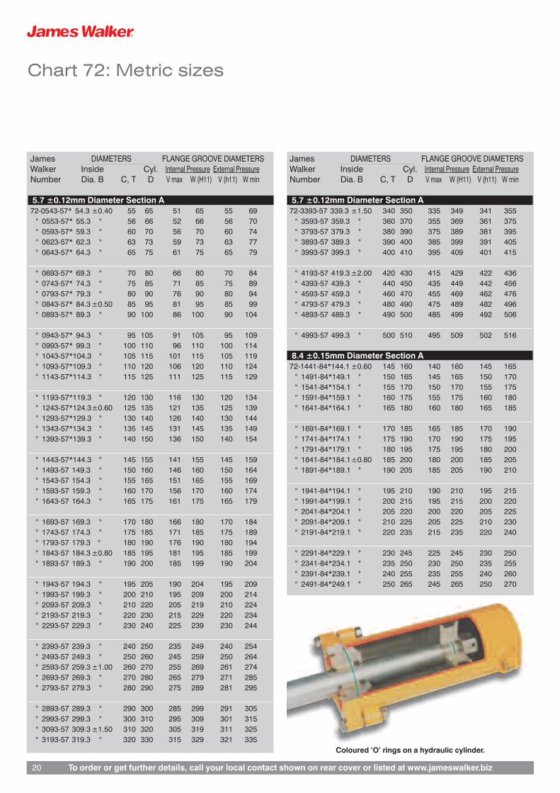
Coloured ‘O’ rings on a hydraulic cylinder.

Chart 17000: Inch sizes
James INCH SIZESWalker Dias. Tol. Dias.Number B,C,P,T on B D, Q
0.094 ±0.003"Diameter Section A
17017* 0.563 ±0.006 0.75017018* 0.594 " 0.78117019* 0.625 " 0.813
17020* 0.656 " 0.84417021* 0.688 " 0.87517022* 0.719 " 0.90617023* 0.750 " 0.93817024* 0.781 " 0.969
17025* 0.813 ±0.008 1.00017026* 0.875 " 1.06317027* 0.938 " 1.12517028* 1.000 " 1.188
0.125 ±0.004"Diameter Section A
17029* 1.000 ±0.008 1.25017030* 1.063 " 1.31317031* 1.125 " 1.37517032* 1.188 " 1.43817033* 1.250 " 1.500
17034* 1.313 " 1.56317035* 1.375 " 1.62517036* 1.438 " 1.68817037* 1.500 ±0.011 1.75017038* 1.563 " 1.813
17039* 1.625 " 1.875
James INCH SIZESWalker Dias. Tol. Dias.Number B,C,P,T on B D, Q
0.125 ±0.004"Diameter Section A
17040* 1.688 ±0.011 1.93817041* 1.750 " 2.00017042* 1.813 " 2.06317043* 1.875 " 2.12517044* 1.938 " 2.188
17045* 2.000 " 2.25017046* 2.125 " 2.37517047* 2.250 " 2.50017048* 2.375 " 2.62517049* 2.500 " 2.750
17050* 2.625 " 2.87517051* 2.750 " 3.00017052* 2.875 ±0.016 3.12517053* 3.000 " 3.250
James INCH SIZESWalker Dias. Tol. Dias.Number B,C,P,T on B D, Q
0.063 ±0.003"Diameter Section A
17001 0.125 ±0.004 0.25017002 0.156 " 0.28117003 0.188 ±0.005 0.31317004 0.219 " 0.34417005 0.250 " 0.375
17006 0.281 " 0.40617007 0.313 " 0.43817008 0.344 " 0.46917009 0.375 " 0.50017010 0.406 ±0.006 0.531
17011 0.438 " 0.56317012 0.469 " 0.59417013 0.500 " 0.625
0.094 ±0.003"Diameter Section A
17014* 0.469 ±0.006 0.65617015* 0.500 " 0.68817016* 0.531 " 0.719
To order your Chart 17000 ‘O’ ring orback-up ring, see page 5.
For housing details refer to pages 24-28.
We originally developed this inch range of‘O’ rings for the Royal Navy. However, itspopularity has led to its use in manyindustries. This is reflected in it beingstocked in our four most popular materials.
If the size you want is not listed, pleaserefer to the inch columns on Chart 50(pages 11-17).
Tolerances on Chart 17000 apply to ourstandard NBR medium nitrile materialPB80. See page 23 for tolerancesapplying to other materials.
* An asterisk symbol denotes that the ringis suitable for both dynamic and staticapplications. Other sizes are notrecommended for dynamic duties.
A
B
To order or get further details, call your local contact shown on rear cover or listed at www.jameswalker.biz 21

To order or get further details, call your local contact shown on rear cover or listed at www.jameswalker.biz22
Chart 17000: Inch sizes
James INCH SIZESWalker Dias. Tol. Dias.Number B,C,P,T on B D, Q
0.188 ±0.005"Diameter Section A
17054* 3.000 ±0.016 3.37517055* 3.125 " 3.50017056* 3.250 " 3.62517057* 3.375 " 3.75017058* 3.500 " 3.875
17059* 3.625 " 4.00017060* 3.750 " 4.12517061* 3.875 " 4.25017062* 4.000 " 4.37517063* 4.125 " 4.500
17064* 4.250 " 4.62517065* 4.375 " 4.75017066* 4.500 " 4.87517067* 4.625 " 5.00017068* 4.750 " 5.125
17069* 4.875 " 5.25017070* 5.000 " 5.37517071* 5.125 ±0.021 5.50017072* 5.250 " 5.62517073* 5.375 " 5.750
17074* 5.500 " 5.87517075* 5.625 " 6.00017076* 5.750 " 6.12517077* 5.875 " 6.25017078* 6.000 " 6.375
James INCH SIZESWalker Dias. Tol. Dias.Number B,C,P,T on B D, Q
0.250 ±0.006"Diameter Section A
17079* 6.000 ±0.021 6.50017080* 6.250 " 6.75017081* 6.500 " 7.00017082* 6.750 " 7.25017083* 7.000 " 7.500
17084* 7.250 ±0.030 7.75017085* 7.500 " 8.00017086* 7.750 " 8.25017087* 8.000 " 8.50017088 8.250 " 8.750
17089 8.500 " 9.00017090 8.750 " 9.25017091 9.000 " 9.50017092 9.250 " 9.75017093 9.500 " 10.000
17094 9.750 " 10.25017095 10.000 " 10.50017096 10.250 ±0.040 10.75017097 10.500 " 11.00017098 10.750 " 11.250
17099 11.000 " 11.50017100 11.250 11.75017101 11.500 " 12.00017102 11.750 " 12.25017103 12.000 " 12.500
James INCH SIZESWalker Dias. Tol. Dias.Number B,C,P,T on B D, Q
0.250 ±0.006"Diameter Section A
17104 12.500 ±0.040 13.00017105 13.000 " 13.50017106 13.500 " 14.00017107 14.000 " 14.50017108 14.500 " 15.000
17109 15.000 " 15.50017110 15.500 " 16.00017111 16.000 ±0.055 16.50017112 16.500 " 17.00017113 17.000 " 17.500
17114 17.500 " 18.00017115 18.000 " 18.50017116 18.500 " 19.00017117 19.000 " 19.50017118 19.500 " 20.000
17119 20.000 ±0.075 20.50017120 20.500 " 21.00017121 21.000 " 21.50017122 21.500 " 22.00017123 22.000 " 22.500
17124 22.500 " 23.00017125 23.000 " 23.50017126 23.500 " 24.00017127 24.000 " 24.500
To order or get further details, call your local contact shown on rear cover or listed at www.jameswalker.biz 23
Non-standard sizes
Methods of production
Using one of the following techniques, weare able to produce any size of ‘O’ ringyou require.
MouldedFor this, our main method of manufacture,we hold a growing inventory approaching10,000 moulding tools. We also have oneof the largest presses of its type in theworld for moulding endless rings up to 2.2metres diameter.
This press is used to produce high-integrity seals, including those for nuclearfuel transportation flasks. The nature ofsuch an application demands stringentquality procedures. James Walker designtechnologists worked closely with ourcustomer on this successful project.
Extruded and mould-joinedThis approach is particularly economicalwhen a high degree of precision isunnecessary: eg, for large diameter non-standard ‘O’ rings in static duties. The ringis made from a length of extruded cord byvulcanising the ends together in amoulding tool.
Rings must have a minimum sectiondiameter of 3mm and a minimum insidediameter of 200mm. Maximum insidediameter is unlimited.
NOTE: This method must not be confusedwith rings joined by contact adhesive.Generally, the use of such adhesivesresults in a less secure join withoperational temperature limitations belowthat of the cord material.
Moulded and mould-joinedThis method is used when the non-standard ‘O’ ring must have a diametersection to very close tolerances and amould-join is acceptable. It is oftenapplied to sizes above 2.2 metresdiameter, when two or more smaller ringsare manufactured, then cut and mould-joined.
Tolerances
Tables 5 and 6 below show the tolerances,on diameter section A and inside diameterB, that can be achieved using variousproduction methods.
A
B
Table 5: Tolerances on DiameterSection A
Diameter Moulded ExtrudedSection A including and
Up to and mould mouldAbove Including joined joined
- 2.7 ±0.08 –2.7 3 ±0.10 +0.38
–0.10
3 3.5 ±0.10 +0.40–0.10
3.5 4 ±0.10 +0.42–0.11
4 5 ±0.12 +0.46–0.12
5 6 ±0.13 +0.50–0.14
6 7 ±0.15 +0.54–0.16
7 8 ±0.18 +0.58–0.18
8 10 ±0.21 +0.66–0.21
10 12.7 ±0.25 +0.75–0.25
All dimensions in millimetres
Table 6: Tolerances on InsideDiameter B
Inside Low HighDiameter B Shrinkage Shrinkage
andUp to and mould
Above Including joined
- 2.6 ±0.10 ±0.132.6 4 ±0.10 ±0.15
4 10 ±0.13 ±0.1810 20 ±0.15 ±0.22
20 38 ±0.20 ±0.2838 70 ±0.28 ±0.40
70 127 ±0.40 ±0.60127 180 ±0.55 ±0.75
180 260 ±0.75 ±1.10260 400 ±1.00 ±1.60
400 500 ±1.40 ±1.90500 700 ±1.90 ±2.60
700 900 ±2.40 ±3.30900 1100 ±2.90 ±4.00
1100 1400 ±3.60 ±5.001400 1700 ±4.30 ±6.00
1700 - ±5.00 ±7.00
All dimensions in millimetres
For standard materialsl PB80 – Low shrinkage.l EP18/H/75, FR10/80, FR58/90,
SIL 80/2, Elast-O-Lion® 101, 180 and985 – High shrinkage.

To order or get further details, call your local contact shown on rear cover or listed at www.jameswalker.biz24
Design notes: General
How ‘O’ rings workRubber has a very high bulk modulus and istherefore virtually incompressible. Thismeans that an ‘O’ ring must be deformed onthe diameter section to give it an initialsealing force within a housing (see Figure 5).
72 and Chart 17000. The amount ofallowable deformation varies according tothe application, as follows:
l GGrroooovvee iinn ccyylliinnddeerr aapppplliiccaattiioonn::A maximum of 3 per cent squeeze isacceptable on an ‘O’ ring outsidediameter to fit a shaft diameter C that isnot covered by JW chart sizes. Seepage 28.
l GGrroooovvee iinn ppiissttoonn aapppplliiccaattiioonnss:: Amaximum of 4 per cent stretch isacceptable on an ‘O’ ring insidediameter to fit a cylinder diameter D thatis not covered by JW chart sizes. Seepage 28.
l FFllaannggee aanndd ttrriiaanngguullaarr ggrroooovveeaapppplliiccaattiioonnss::A maximum of 2 per cent stretch isacceptable on an ‘O’ ring inside diameterwhen the seal is used on an externalpressure flange, or housed in a triangulargroove. Likewise, a maximum of 1 percent squeeze is acceptable on an ‘O’ring outside diameter when the seal isused on an internal pressure flange.
Cylinder and piston housing tolerancesIt is important that tolerances on housingdiameters for cylinders and pistons meetthe requirements of the formulae given onpage 28 (ie, dimensions C and D asshown on Figures 9-12).
Surface finish of metal partsFor maximum seal life the surface finish ofmetal parts in contact with an ‘O’ ringshould not exceed:
l 0.8µm (32µin) CLA or Ra in the case ofstatic parts, or
l 0.4µm (16µin) for moving parts.
A finish finer than 0.15µm (6µin) should beavoided in dynamic applications as alubricating film may not be retained. Fordetails of these finishes, please refer toBS1134: Assessment of surface texture.
Diametral clearance GUnder no circumstances should themaximum total diametral clearance (Gmax) indicated on our housing tables(pages 26-27) be exceeded. This is toensure that, if complete shaft offsetoccurs, the maximum extrusion gap at anypoint of the ‘O’ ring does not exceed G.
Pressure restrictions‘O’ rings are generally suitable forpressures up to 100bar. Where higherpressures are involved, we recommendthe use of back-up rings, as described onpage 10.
For stuffing box applications werecommend piston-type grooves,although triangular grooves are generallyacceptable for pressures below 100bar(see Figures 7 and 8).
Pressure
Pressure
G2
G2
G2
G2
Pressure
Pressure
G2
G2
G2
G2
Pressure
Pressure
G2
G2
G2
G2
Pressure
Pressure
G2
G2
G2
G2
Figure 5
Figure 7
Figure 8
Figure 6
When system pressure is applied, the ‘O’ring deforms further (see Figure 6). Butbecause of the initial squeeze, the sealingforce always exceeds the force exerted onthe ‘O’ ring by the system pressure.
At higher pressures, back-up rings may berequired to prevent ‘O’ ring extrusion (seepage 10). Leakage problems often arisedue to lack of initial squeeze, or the ‘O’ring diameter section being too large forits housing.
Reciprocating applications‘O’ rings marked (*) on our charts arerecommended for both static andlight/medium reciprocating duties. Othersizes are not recommended for dynamicapplications.
Rotary applications‘O’ rings may be used for rotatingapplications where peripheral speeds arelow. For recommendations, please consultour Technical Services Team.
‘O’ ring tolerancesTolerances quoted on Charts 50, 72 and17000 apply to our standard NBR mediumnitrile material PB80. For tolerances applyingto other materials, see page 23.
Non-standard housing diametersIndividual ‘O’ rings can be stretched orsqueezed very slightly to fit housingdiameters that do not match thedimensions specified in Chart 50, Chart
For flange applications, ‘O’ rings willnormally be suitable for sealing pressuresabove 100bar where metal-to-metalcontact prevents extrusion.
Complex dynamic, high vacuum or hightemperature dutiesGroove dimensions quoted allow forexpansion, swell and retention ofinterference over the longest possible seallife.
However, these dimensions may not suitcomplex dynamic applications, staticduties with high vacuum, or hightemperature duties. If in doubt, pleaseconsult our Technical Services Team.

To order or get further details, call your local contact shown on rear cover or listed at www.jameswalker.biz 25
Design notes: General
Six useful hints
l Select the largest diameter section‘O’ ring to fit the nominal groove size.This will absorb adverse tolerancesin metal parts and aid durability,particularly in high temperatureapplications.
Explosive decompression (ED)environments are an exception – seepage 9. To minimise gas permeation,the smallest possible diametersection, that does not compromisemechanical sealing efficiency, shouldbe used. Please ask for separateliterature on our high performanceelastomers and ED resistantmaterials.
l Consider how the ‘O’ ring will passover other parts during assembly.Provide the lead-ins asrecommended on page 28 (Figures9 and 11), remove all burrs, and usethin fitting sleeves whereappropriate.
l Smear seals lightly with a suitablelubricant before assembly (see page8 for recommendations).
l On reciprocating applications alwayscheck whether a standard ‘O’ ring issuitable. Those that are suitable areindicated (*) on Chart 50, Chart 72and Chart 17000.
l With a cylinder or piston groove,where the ‘O’ ring inside diameter isless than three times the diametersection, a two part recess – withcomponent split at the ‘O’ ringhousing – may be required tofacilitate assembly. This is because itis impractical to stretch or squeezethe seal into position without causingdamage.
l Always store ‘O’ rings underconditions that meet therequirements of BS ISO 2230 Rubberproducts – guidelines for storage, orBS F68: Controlled storage ofrubbers for use in aerospaceapplications.

To order or get further details, call your local contact shown on rear cover or listed at www.jameswalker.biz26
Design notes: Housings
Table 7: Metric Groove Dimensions All dimensions in millimetres.Diameter Groove Width E Radial Diametrical Flange Groove Triangular Groove Groove Radii Dovetail GrooveSection Depth Clearance
A ‘O’ring only +1 back-up +2 back-up F G max Depth H K min L min Chamfer M R max R1 max R2 Depth X Width Y
1.0/1.02 1.5/1.6 # # 0.81/0.86 0.11 0.7/0.8 1.8 # # # 0.2 0.11/0.22 # #1.27 1.8/1.9 # # 1.06/1.11 0.11 0.9/1.0 2.1 # # # 0.3 0.11/0.22 # #
1.5/1.52 2.1/2.2 # # 1.26/1.32 0.12 1.1/1.2 2.4 3.0 2.08/2.20 0.8 0.3 0.12/0.24 # #1.6 2.3/2.5 3.7/3.9 5.0/5.2 1.18/1.25 0.12 1.2/1.3 2.4 4.0 2.20/2.32 0.8 0.2 0.20/0.40 1.37/1.43 1.34/1.40
1.78 2.3/2.5 3.8/3.9 5.3/5.4 1.52/1.57 0.13 1.3/1.5 2.4 4.8 2.41/2.54 0.8 0.8 0.13/0.25 1.50/1.56 1.50/1.56
2.0 2.6/2.7 4.1/4.2 5.6/5.7 1.72/1.79 0.12 1.6/1.7 2.8 4.0 2.71/2.83 1.0 0.4 0.12/0.24 1.65/1.72 1.70/1.772.4 3.2/3.4 4.6/4.8 6.0/6.2 1.97/2.09 0.14 1.7/1.8 3.7 5.0 3.30/3.42 1.3 0.5 0.20/0.40 1.96/2.04 2.05/2.132.5 3.2/3.3 4.7/4.8 6.2/6.3 2.17/2.25 0.13 2.0/2.1 3.4 5.0 3.46/3.59 1.3 0.5 0.13/0.26 2.05/2.13 2.15/2.23
2.62 3.5/3.7 5.0/5.1 6.5/6.6 2.31/2.39 0.13 2.1/2.3 3.6 6.4 3.68/3.81 1.0 0.8 0.13/0.25 2.16/2.24 2.26/2.343.0 4.0/4.2 5.4/5.6 6.8/7.0 2.50/2.65 0.15 2.2/2.3 4.5 6.0 4.20/4.32† 2.0 1.0 0.20/0.40 2.46/2.55† 2.58/2.67
3.5/3.53 4.7/4.9 6.2/6.4 7.7/7.9 3.10/3.18 0.15 2.8/3.0 4.8 7.9 4.95/5.08† 1.5 0.8 0.13/0.25 2.89/2.99† 3.03/3.134.0 5.1/5.3 6.6/6.8 8.1/8.3 3.52/3.62 0.15 3.2/3.4 5.5 8.0 5.75/5.90 2.0 0.8 0.15/0.30 3.32/3.42† 3.48/3.584.1 5.5/5.7 7.1/7.3 8.7/8.9 3.50/3.67 0.16 3.1/3.2 6.0 8.0 5.60/5.72† 2.5 1.0 0.20/0.40 3.39/3.50† 3.59/3.704.5 5.8/6.0 7.6/7.8 9.4/9.6 3.96/4.07 0.16 3.7/3.9 6.0 9.0 6.45/6.61 2.3 0.9 0.16/0.32 3.74/3.85† 3.92/4.035.0 6.4/6.6 8.2/8.4 10.0/10.2 4.42/4.54 0.16 4.1/4.3 6.7 10.0 7.18/7.34 2.5 1.0 0.16/0.32 4.23/4.35 4.37/4.49
5.33 7.0/7.2 8.8/9.0 10.6/10.8 4.67/4.78 0.18 4.3/4.5 7.1 11.1 7.49/7.62 2.3 0.8 0.13/0.25 4.54/4.67 4.64/4.775.7 7.5/7.7 9.3/9.5 11.1/11.3 4.95/5.18 0.18 4.4/4.5 8.1 10.0 7.80/7.92† 3.0 1.0 0.20/0.40 4.80/4.94 4.98/5.126.0 7.8/8.0 9.6/9.8 11.4/11.6 5.31/5.45 0.18 5.0/5.2 7.9 12.0 8.64/8.82 3.0 1.2 0.18/0.36 5.02/5.16 5.25/5.39
6.99/7.0 9.4/9.6 12.0/12.2 14.6/14.8 6.22/6.35 0.20 5.9/6.1 9.4 14.3 10.03/10.16 2.5 0.8 0.13/0.25 5.85/6.01 6.12/6.288.0 10.7/10.9 13.3/13.5 15.9/16.1 7.09/7.27 0.20 6.7/6.9 10.6 16.0 11.61/11.81 4.0 1.6 0.20/0.40 6.70/6.88 7.01/7.19
8.4 11.0/11.2 13.6/13.8 16.2/16.4 7.50/7.75 0.20 6.6/6.7 12.0 14.0 11.50/11.62† 4.0 1.0 0.20/0.40 7.02/7.21 7.34/7.539.0 12.3/12.5 15.6/15.8 18.9/19.1 7.97/8.17 0.21 7.5/7.7 12.1 18.0 13.08/13.29 4.5 1.8 0.21/0.42 7.54/7.74 7.89/8.09
9.5/9.53 13.1/13.3 16.4/16.6 19.7/19.9 8.43/8.64 0.22 8.0/8.2 12.7 19.0 13.83/14.05 4.8 1.9 0.22/0.44 7.97/8.18 8.34/8.5510.0 13.8/14.0 17.1/17.3 20.4/20.6 8.89/9.10 0.23 8.4/8.6 13.3 20.0 14.58/14.81 5.0 2.0 0.23/0.46 8.41/8.62 8.80/9.01
12.5/12.7 18.5/18.8 21.8/22.1 25.1/25.4 11.13/11.39 0.26 10.5/10.8 17.4 25.0 18.30/18.56 6.3 2.5 0.26/0.52 10.52/10.78 11.01/11.27
Table 8: Inch Groove Dimensions All dimensions in inches.Diameter Groove Width E Radial Diametrical Flange Groove Triangular Groove Groove Radii Dovetail GrooveSection Depth Clearance
A ‘O’ring only +1 back-up +2 back-up F G max Depth H K min L min Chamfer M R max R1 max R2 Depth X Width Y
0.040 .059/.063 # # .032/.034 .004 .028/.032 .068 # # # .008 .004/.008 # #0.050 .069/.073 # # .042/.044 .004 .037/.041 .078 # # # .010 .004/.008 # #0.060 .080/.085 # # .051/.053 .005 .045/.050 .091 .120 .082/.087 .030 .012 .005/.010 # #0.063 .084/.089 .142/.147 .200/.205 .053/.055 .005 .047/.052 .094 .125 .086/.091 .031 .013 .005/.010 .054/.056 .053/.0550.070 .089/.099 .147/.152 .205/.210 .060/.062 .005 .051/.061 .095 .188 .095/.100 .030 .030 .005/.010 .059/.062 .059/.062
0.094 .121/.126 .179/.184 .237/.242 .081/.084 .005 .075/.080 .129 .188 .129/.134 .047 .019 .005/.010 .077/.080 .080/.0830.103 .136/.146 .194/.199 .252/.257 .091/.094 .005 .081/.091 .140 .250 .145/.150 .040 .030 .005/.010 .085/.088 .089/.0920.125 .159/.164 .217/.222 .275/.280 .110/.114 .005 .102/.107 .168 .250 .183/.188 .063 .025 .005/.010 .103/.107† .107/.1110.139 .183/.193 .241/.247 .299/.305 .122/.125 .006 .110/.120 .190 .313 .195/.200† .060 .030 .005/.010 .115/.119† .120/.1240.188 .240/.246 .312/.318 .384/.390 .166/.171 .006 .155/.161 .248 .375 .269/.275 .094 .038 .006/.012 .156/.161† .163/.168
0.210 .276/.286 .348/.355 .420/.427 .184/.188 .007 .170/.180 .280 .438 .295/.300 .090 .030 .005/.010 .179/.184 .183/.1880.250 .328/335 .430/.437 .532/.539 .221/.227 .007 .207/.214 .333 .500 .360/.367 .125 .050 .007/.014 .208/.214 .218/.2240.275 .370/.380 .472/.480 .574/.582 .245/.250 .008 .231/.241 .370 .563 .395/.400 .100 .030 .005/.010 .230/.236 .241/.2470.375 .514/.523 .644/.653 .774/.783 .333/.341 .009 .314/.323 .501 .750 .545/.554 .188 .075 .009/.018 .315/.323 .329/.3370.500 .718/.728 .848/.858 .978/.988 .446/.456 .010 .421/.431 .674 1.000 .733/.743 .250 .100 .010/.020 .421/.431 .441/.451
Key: Chart 50 Chart 72 Chart 17000 BS 1806, BS 4518 and BS 5106 figures are given in red.
# Diameter Section A indicated is too small for this groove type† These dimensions can only be used with moulded ‘O’ rings.
Use Tables 10 and 11, page 27 for ‘O’ rings manufactured by other methods.

Design notes: Housings
For ‘O’ rings manufactured by extrusion
Table 9: BS 4500 ISO Limits and FitsExtract (See Figures 13 - 15, page 28)
Nom. Diameter Toleranceup to and
Above including H11 h11
- 3 +0/+0.060 –0/–0.0603 6 +0/+0.075 –0/–0.0756 10 +0/+0.090 –0/–0.090
10 18 +0/+0.110 –0/–0.11018 30 +0/+0.130 –0/–0.130
30 50 +0/+0.160 –0/–0.16050 80 +0/+0.190 –0/–0.19080 120 +0/+0.220 –0/–0.220
120 180 +0/+0.250 –0/–0.250180 250 +0/+0.290 –0/–0.290
Table 9 continued
Nom. Diameter Toleranceup to and
Above including H11 h11
250 315 +0/+0.320 –0/–0.320315 400 +0/+0.360 –0/–0.360400 500 +0/+0.400 –0/–0.400500 630 +0/+0.440 –0/–0.440630 800 +0/+0.500 –0/–0.500
800 1000 +0/+0.560 –0/–0.5601000 1250 +0/+0.660 –0/–0.6601250 1600 +0/+0.780 –0/–0.7801600 2000 +0/+0.920 –0/–0.9202000 2500 +0/+1.100 –0/–1.100
All dimensions in millimetres
Table 10: Table 11:Triangular DovetailGroove Sizes Groove Sizes
Diameter Triangular Diameter DovetailSection A Chamfer M Section A Depth X
Metric (mm) Metric (mm)
3.0 4.48/4.63 3.0 ¥3.5/3.53 5.10/5.25 3.5/3.53 ¥
4.1 6.00/6.16 4.0 3.48/3.585.7 8.18/8.36 4.1 3.59/3.708.4 12.18/12.38 4.5 3.88/3.99
Inch Inch
0.139 .201/.207 0.125 ¥0.139 ¥0.188 .159/.164
¥ ’O’ rings not suitable for dovetailgrooves.
General InformationHealth warning: If PTFE products are heated to elevated temperatures, fumes will be produced which may give unpleasant effects, if inhaled. Whilst some fumes are emitted below 300°C, the effect atthese temperatures is negligible. Care should be taken to avoid contaminating tobacco with PTFE particles or dispersion which may remain on hands or clothing. Material Safety Data Sheets (MSDS)are available on request.
Information in this publication and otherwise supplied to users is based on our general experience and is given in good faith, but because of factors which are outside our knowledge and control andaffect the use of products, no warranty is given or is to be implied with respect to such information. Specifications are subject to change without notice. Statements of operating limits quoted in thispublication are not an indication that these values can be applied simultaneously. Materials Safety Data Sheets (MSDS) are available on request.
To order or get further details, call your local contact shown on rear cover or listed at www.jameswalker.biz 27

Design notes: Housings
Housing arrangements
15 - 20°Shaftdiameter
C
E
F
Groovediameter
G totaldiametralclearance
Max. leadin dia.
Max. groove dia. = C min. + 2F max.Min. groove dia. = C max. + 2F min.
Min.groove dia. 2A max. - G-=
H
K
P h11
Directionof pressure
Min. leadin dia.
Max.groove dia.
Groovediameter
Max. groove dia. = D min. - 2F min.Min. groove dia. = D max. - 2F max.
15 - 20°
E
D
F
G totaldiametralclearance
cylinderdiameter
= + 2A max. + G
RadiusR2
RadiusR1 max.
0 - 5°
A
B
List of symbols
The following symbols are usedthroughout this guide:
A ‘O’ ring diameter section
B ‘O’ ring inside diameter
C Shaft diameter
D Cylinder diameter
E Groove width
F Groove radial depth
G Maximum diametral clearance
H Flange groove depth
h11 BS 4500 tolerance (shafts)
H11 BS 4500 tolerance (holes)
K Minimum flange groove width
L Minimum spigot length
M Triangular groove chamfer
P Flange groove inside diameter
Q Flange groove outside diameter
R Triangular groove radius
R1 Corner radius (maximum) atgroove base
R2 Corner radius at groove entrance
T Triangular groove inside diameter
V BS 4518 flange groove insidediameter
W BS 4518 flange groove outsidediameter
X Dovetail groove depth
Y Dovetail groove width
Figure 9: Groove in cylinder Figure 13: Groove in flange, externalpressure
H
K
Q H11
Directionof pressure
H
W
V
Maximumradius R
M
45∞
L
T
G totaldiametralclearance
20 - 25°
X
Y
A + B
Maximumradius 2G
Radiusmin. Gmax. 2G
Figure 14: Groove in flange, internalpressure
Figure 15: Groove in flange, Chart 72
Figure 16: Triangular groove
Figure 18: Groove radii and taper for figures9 - 15
Figure 17: Dovetail groove
Figure 10: Plug groove, terminology asfigures 9 and 18
Figure 11: Groove in piston
Figure 12: Plug groove, terminologyas figures 11 and 18
To order or get further details, call your local contact shown on rear cover or listed at www.jameswalker.biz28

‘O’ ring cords & kits
‘O’ ring kits
These three boxedkits representexcellent value formoney in terms ofquantity, quality andconvenience.
Each kit has beencarefully assembledfor maintenanceengineers andequipmentrefurbishers whoneed a good selection of ringsconstantly available to suit manyindustrial applications.
The boxes are designed to withstandindustrial maintenance activities, andhave partitions to hold all itemsseparately and securely. From the kitlayouts, users can readily see whenthey are running low on a particularsize of ring or cord.
‘O’ ring sealing kit – metric sizes(JW order code ZL000186)Box containing nitrile (NBR) elastomerrings of 70 IRHD:� 404 ‘O’ rings in total.� In 30 sizes ranging from 3mm ID x
2mm section up to 45mm ID x 4mmsection.
NOTE: Hardeness values quoted arenominal.
‘O’ ring sealing kit – inch sizes(JW order code ZL000097)Box containing nitrile (NBR) elastomerrings of 70 IRHD:� 382 ‘O’ rings in total.� In 30 sizes ranging from ⁄÷• inch ID x
⁄÷¡§ inch section up to 1‹÷¢ inch ID x‹÷¡§ inch section.
Service kit – ‘O’ ring cord(JW order code ZL000275)Box containing tools and nitrile (NBR)elastomer ‘O’ ring cord of 70 IRHD:� 14 off 2m lengths: 1.78mm
diameter (0.070 inch), 2.0mm,2.4mm, 2.62mm (0.103 inch),3.0mm, 3.5mm (0.138 inch),4.0mm, 4.5mm, 5.0mm, 5.33mm(0.210 inch), 5.7mm, 6.0mm,6.99mm (0.275 inch), 8.0mm.
� Tape measure, retractable bladeknife, splicing aid and adhesive forforming rings.
� Full instructions.
‘O’ ring cord
We manufacture a large selection of‘O’ ring cord in metric and inch crosssections in the following elastomers:
FR10/80 Fluorocarbon (80 IRHD)PB70 Nitrile (70 IRHD)EP21/E/80 Ethylene-propylene (80 IRHD)GN/W/70 Neoprene (70 IRHD)
Standard cross sections:1.6mm ⁄÷¡§ inch1.78mm 0.070 inch2.0mm2.4mm ‹÷#™ inch2.62mm 0.103 inch3.0mm3.18mm ⁄÷• inch3.53mm 0.139 inch4.0mm fi÷#™ inch4.5mm4.76mm ‹÷¡§ inch5.0mm5.33mm 0.210 inch5.7mm6.0mm6.35mm ⁄÷¢ inch6.99mm 0.275 inch8.0mm fi÷¡§ inch8.73mm ⁄⁄÷#™ inch9.5mm ‹÷• inch10mm10.32mm ⁄‹÷#™ inch11.11mm ‡÷¡§ inch11.91mm ⁄fi÷#™ inch12.7mm ⁄÷™ inch
How supplied: by the metre to anylength.
Most of the above elastomers andcord sizes are available from stock oron short lead times. Other sizes andelastomers can be supplied onrequest. All these cords aremanufactured to BS 3734-1 andISO3302-1.
Special packaging and kits
Special packaging and baggingcan be provided for all of our ‘O’rings – from individually baggedrings to complete sealing kits
containing a variety of sizes andmaterials.
These can be custom-brandedand over printed with dedicatedpart numbers to simplifyordering, stocking and issuingroutines.
Your own company name andlogo can be printed on the bag orlabel to provide a custompackaged kit with your ownreferences to save additionalrepackaging if you are re-selling.
To order or get further details, call your local contact shown on rear cover or listed at www.jameswalker.biz 29

Ask for these free guides to James Walker’s products and services.
BP4179 906/10mML-011653
Compression packings Gaskets & jointings Hydraulic sealing products
Registered Office: Lion House, Oriental Road, Woking, Surrey GU22 8AP, UK. Reg. No. 2432592 England© James Walker 2006
CERTIFICATE No. FM 01269
BS EN ISO 9001:2000
James Walker & Co LtdCustomer Support Centre1 Millennium Gate, Westmere DriveCrewe, Cheshire CW1 6AY, UKTel: +44 (0)1270 536000Fax: +44 (0)1270 536100Email: [email protected]
James Walker Australia Pty LtdTel: +61 2 9644 9755Fax: +61 2 9645 2009Email: [email protected]
James Walker Benelux(Belgium)Tel: +32 3 820 7900Fax: +32 3 828 5484Email: [email protected](Netherlands)Tel: +31 (0)186 633111Fax: +31 (0)186 633110Email: [email protected]
James Walker ChinaTel: +86 215117 5802Fax: +86 215116 6899Eamil: [email protected]
James Walker Deutschland GmbHTel: +49 (0)40 386 0810Fax: +49 (0)40 389 3230Eamil: [email protected]
James Walker France SASTel: +33 (0)437 497480Fax: +33 (0)437 497483Email: [email protected]
James Walker Iberica SATel: +34 94 4470099Fax: +34 94 4471077Email: [email protected]
James Walker Ireland LtdTel: +353 (0)1 454 2500Fax: +353 (0)1 454 4561Email: [email protected]
James Walker Italiana srlTel: +39 02 257 8308Fax: +39 02 263 00487Email: [email protected]
James Walker Mfg Co (USA)Tel: +1 708 754 4020Fax: +1 708 754 4058Email: [email protected]
James Walker New Zealand LimitedTel: +64 (0)9 272 1599Fax: +64 (0)9 272 3061Email: [email protected]
James Walker Norge ASTel: +47 22 706800Fax: +47 22 706801Email: [email protected]
James Walker Singapore Pte LtdTel: +65 6777 9896Fax: +65 6777 6102Email: [email protected]
James Walker South Africa (PTY) LtdTel: +27 (0)31 205 6251/2/3Fax: +27 (0)31 205 6266Email: [email protected]
James Walker Group companies