º floors - northumbria universitynuweb.northumbria.ac.uk/bedemo/domestic_floors/media/extra... ·...
TRANSCRIPT

FLO
OR
Sº
SECTION 3

Contents
Floors
100
The chart below can be usedas both a contentslist and a trackingmechanism, as shown on page 18
Total Insulation Solutions
Whatever you need to insulate, KnaufAlcopor has the answer.We havesolutions for the thermal insulation, acoustic insulation and fireprotection for buildings, building services and industrial applications
As the UK’s largest manufacturer of insulation products, we can provideyou with the most appropriate glass mineral wool, rock mineral wool orextruded polystyrene product to meet your insulation requirements,backed up with the best all round service and support package.
Floatingchipboard deck
Page 109
Ground FloorsDesign ConsiderationsPage 102
FloorsProduct Selector Page 101
Insulationbelow slab
Page 105
Floatingscreed
Page 107
Upper FloorsDesign ConsiderationsPage 112
ThermalApplications
Suspendedtimber
Page 111
FireApplications
Floatingscreed
Page 113
Floatingchipboard deck
Page 114
Suspendedtimber
Page 115
Refurbishment ofseparating floor
Page 116

101
Product Selector
Floors
Tel 01744 693885 E-mail [email protected]
Floo
rsS
elec
tor
Product
Belowconcrete
slab
Underfloatingscreed
Under floatingchipboard
deck
Timbersuspended
floor
Upgrading oftimber
suspendedfloor
p 107 p 109
p 106 p 108 p 110
p 111
Ground floors-thermal
Polyfoam º Floorboard • • •
Crown º Floor Slab • • •
Crown º Wool •Upper floors-thermal
Polyfoam º Floorboard • •
Crown º Wool •Upper floors-fire
Rocksil Slab RS33 •p 116
p 115
p 105
p 113 p 114

Thermal Insulation
Ground Floors – Design
GeneralThe two most important factors toconsider when insulating a ground floorare:
• What thickness of insulation will berequired to meet the BuildingRegulations?
• Where is the insulation to bepositioned within the floor structure?
Other design considerations includepreventing condensation, minimising airleakage, thermal bridging and the compressionresistance of the insulation.
Building RegulationRequirementsThe table shows the U-value requirementsin the Building Regulations for groundfloors.
Calculation of U-valuesUnlike walls and roofs, the heat lossthrough a ground floor varies with its sizeand shape.The Building Regulationsrequire that when ground floor U-valuesare calculated, BS EN ISO 13370: 1998should be used.As well as the groundfloor’s perimeter to area ratio, the BritishStandard also takes into account theinsulating effect of the external walls andthe sub space below suspended groundfloors.
The measurement of the perimeter andarea should be to the finished insidesurfaces of the perimeter walls thatenclose the heated space. Projecting baysshould be included, but unheated spacessuch as porches or garages should beexcluded.
In the case of semi-detached, terraceddwellings and blocks of flats the floor
The graphs assume the ground has athermal conductivity of 1.5 W/mK.The U-values for Crown Wool assume it isplaced between 50mm timber floor joistsspaced at 600mm centres.To calculate U-values to your own specificrequirements, KnaufAlcopor recommendthe use of its Architectural CalculationSuite (ACS) version 5.
The following worked example illustrateshow to use the graphs.
102
0.1 0.2 0.3 0.4 0.5 0.6 0.7 0.8Ratio of perimeter (m) to area (m2)
0.35
0.30
0.20
0.10
U-v
alu
es
(W/m
2 K)
0.25
0.15
60mm80mm
100mm
150mm
200mm
0.35
0.30
0.20
0.10
U-v
alu
es
(W/m
2 K)
0.25
0.15
0.1 0.2 0.3 0.4 0.5 0.6 0.7 0.8Ratio of perimeter (m) to area (m2)
25mm 35mm50mm
75mm
100mm
Suspended timber ground floor U-values using Crown Wool
Building Regulation requirementsfor ground floors
U-value (W/m2K)
Dwellings Central heating with SEDBUK 0.25value from Table 2 (In Building Regulations)
Other heating systems (1) 0.22(Scotland only)
Buildings other than dwellings 0.25
Note (1) Other gas or oil central heating system, or an electric heating system or solid fuel central heating or undecided – this U-value is applicable only in Scotland.
U-values for solid ground floor using Polyfoam Floorboard
0.1 0.2 0.3 0.4 0.5 0.6 0.7 0.8Ratio of perimeter (m) to area (m2)
0.35
0.30
0.20
0.10
U-v
alu
es
(W/m
2 K)
0.25
0.15
25mm 35mm50mm
75mm
100mm
U-values for Beam and block ground floor with PolyfoamFloorboard insulation and chipboard finish
dimensions can either be taken as those ofthe individual dwellings themselves, or ofthe whole building.When consideringextensions to existing buildings the floordimensions may be taken as those of thecomplete building including the extension.
Determining the U-valueThe graphs below allow U-values to bedetermined for the range of KnaufAlcoporinsulation materials recommended forinsulating ground floors.
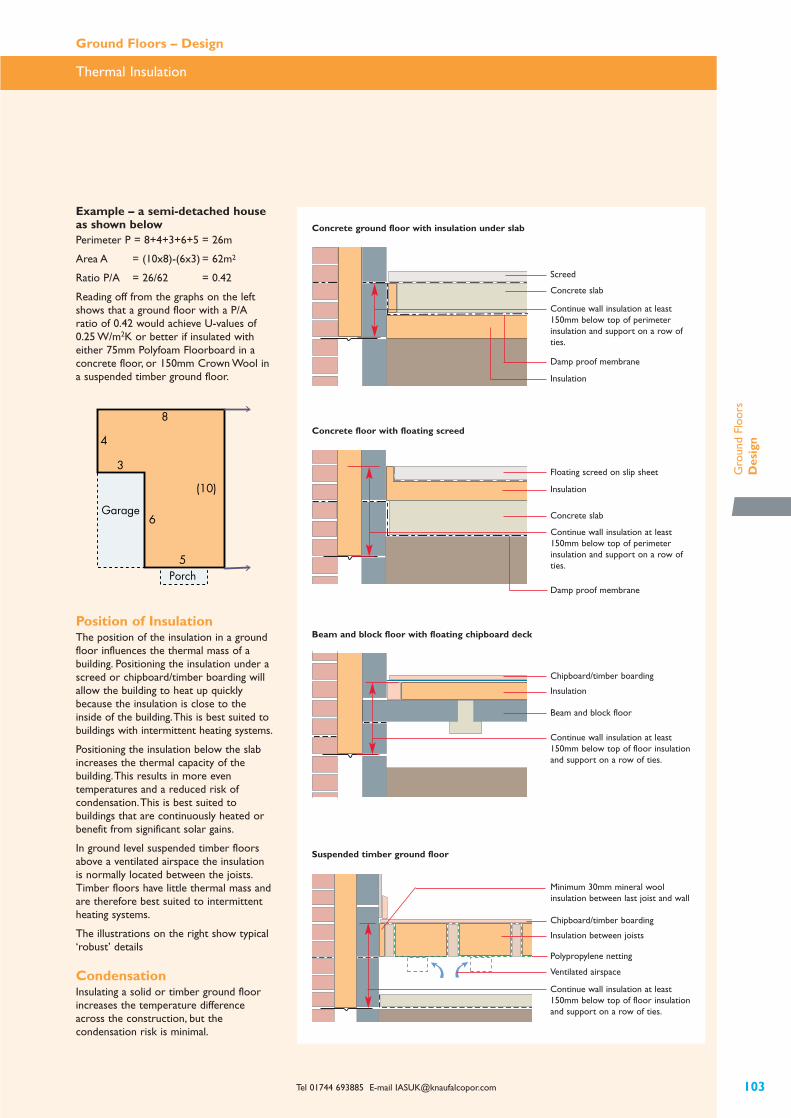
Example – a semi-detached houseas shown belowPerimeter P = 8+4+3+6+5 = 26m
Area A = (10x8)-(6x3) = 62m2
Ratio P/A = 26/62 = 0.42
Reading off from the graphs on the leftshows that a ground floor with a P/Aratio of 0.42 would achieve U-values of 0.25 W/m2K or better if insulated witheither 75mm Polyfoam Floorboard in aconcrete floor, or 150mm Crown Wool ina suspended timber ground floor.
Tel 01744 693885 E-mail [email protected] 103
Thermal Insulation
Ground Floors – Design
Gro
und
Floo
rsD
esig
n
3
4
8
(10)
5
6Garage
Porch
Position of InsulationThe position of the insulation in a groundfloor influences the thermal mass of abuilding. Positioning the insulation under ascreed or chipboard/timber boarding willallow the building to heat up quicklybecause the insulation is close to theinside of the building.This is best suited tobuildings with intermittent heating systems.
Positioning the insulation below the slabincreases the thermal capacity of thebuilding.This results in more eventemperatures and a reduced risk ofcondensation.This is best suited tobuildings that are continuously heated orbenefit from significant solar gains.
In ground level suspended timber floorsabove a ventilated airspace the insulationis normally located between the joists.Timber floors have little thermal mass andare therefore best suited to intermittentheating systems.
The illustrations on the right show typical‘robust’ details
CondensationInsulating a solid or timber ground floorincreases the temperature differenceacross the construction, but thecondensation risk is minimal.
Floating screed on slip sheet
Insulation
Concrete slab
Damp proof membrane
Chipboard/timber boarding
Insulation
Beam and block floor
Insulation between joists
Chipboard/timber boarding
Polypropylene netting
Continue wall insulation at least150mm below top of floor insulationand support on a row of ties.
Ventilated airspace
Concrete slab
Insulation
Damp proof membrane
Screed
Continue wall insulation at least150mm below top of perimeterinsulation and support on a row ofties.
Continue wall insulation at least150mm below top of perimeterinsulation and support on a row ofties.
Continue wall insulation at least150mm below top of floor insulationand support on a row of ties.
Concrete floor with floating screed
Beam and block floor with floating chipboard deck
Suspended timber ground floor
Concrete ground floor with insulation under slab
Minimum 30mm mineral woolinsulation between last joist and wall

Thermal Insulation
Ground Floors – Design
104
Dead loads applied by various building componentsElement Dead load (kN/m2)
Flooring grade chipboard 0.1 to 0.2
65mm concrete screed 1.50
75mm concrete screed 1.75
150mm concrete floor slab 3.50
Additional design load to BS 6399: Part 1: 1996 (dwellings) 1.50
Avoiding air leakage in suspendedtimber ground floors
Bead of sealant
Expanding foamtape compressedwhen skirtingfixed
The applied load has two components:
• the dead load, which is due to theweight of the materials laid on theinsulant, and
• the design load.
BS 6399: Part 1: 1996 suggests that indwellings, a design load of 1.5 kN/m2
should be allowed for in all cases.
The dead loads applied by various buildingcomponents are shown in the table.TheApplications section shows thecompression resistance of individualinsulants, where relevant.
British StandardsDesigners should consult BS 5669: Part 2:1989 and BS 7916:1998 when selectingchipboard or other floor decking boards.
Guidance on the design and installation ofconcrete bases and screeds to receive in-situ flooring is given in BS 8204: Part 1:1999.
Advice on resilient floor coverings,including recommendations for suitablebases is given in BS 8203:1996.
A vapour barrier is not normally requiredfor most ground floor constructions.However, a vapour barrier should beinstalled between the insulation and achipboard floor, especially if there is a riskof excessive moisture from the floor slabdrying out.
Thermal BridgingThermal bridges are a significant source ofheat loss.They may also cause localisedcondensation and mould growth,depending on the change in temperaturelevels at these locations.
Correct detailing at the junction of thefloor slab and external wall, as shown inthe drawings on the previous page, willreduce thermal bridging and thus the riskof condensation.
Timber joists, and timber battenssupporting floor panels have a greater heatloss than thermal insulation materials.The U-value tables in the Applications sectionallow for thermal bridging by timbermembers, where relevant.
Air LeakageWith suspended timber ground floors,care is needed to minimise air leakagefrom the ventilated sub floor void into theheated space.As well as gluing the jointsbetween the floor deck panels, the floorperimeter should be sealed by applyingexpanded foam tape under the skirtingand a continuous bead of sealant to theback of the skirting prior to fixing.
Compressive StrengthAll materials are compressed under load.Insulation materials used in floors shouldbe capable of accommodating the appliedloads with the minimum of compression.

KnaufAlcopor recommend Polyfoam Floorboard for the thermalinsulation of solid ground floors with insulation below the slab.Crown Floor Slab can also be used in this application where amineral wool product is preferred.
Tel 01744 693885 E-mail [email protected] 105
Insulation Below Slab – Polyfoamº Floorboard
Ground Floors – Applications
Gro
und
Floo
rsT
herm
al A
pplic
atio
ns
Polyfoam Floorboard is made from HCFC/CFC-free, 100% ozone friendly extrudedpolystyrene and formed into rigid boards.The boards are available in fourcompressive strengths:
• 220 kPa – domestic loading
• 350 and 500 kPa – high loads such asvehicle access, including fork lift trucks
• 700 kPa – high loads including rackingsystems.
Polyfoam Floorboard 500 is supplied withinterlocking rebated edges. PolyfoamFloorboard 220, 350 and 700 are suppliedwith square edges.
Typical ConstructionA solid concrete ground floor slab on adamp proof membrane on PolyfoamFloorboard insulation laid directly overblinded hardcore.A strip of insulation,minimum 25mm thick, should be placed
vertically at the slab perimeter tominimise thermal bridging.The concreteslab may be screeded or alternatively havea power float finish.
This construction is also suitablefor basements.
Typical SpecificationThe whole of the ground floor areabetween brick, block or concrete subwallsto be insulated with Polyfoam Floorboard220*/ 350*/ 500*/ 700*, (*delete asrequired), ….mm thick, and laid directlyover blinded hardcore.A strip ofperimeter insulation, minimum 25mmthick, to be placed vertically against thesubwalls tothe depth of the concrete slab.
The insulation to be overlaid with a dampproof membrane, which should lap theperimeter wall dpc. Concrete slab andfloor finish as specified by the designer.
Performance
Thermal performancePolyfoam Floorboard 220 and 700 have athermal conductivity of 0.028 W/mK.Polyfoam Floorboard 350 and 500 have athermal conductivity of 0.027 W/mK.
The table gives U-values for a range ofperimeter/area ratios. For an explanationof how to calculate ground floor U-values,see page 102.
Fire performanceThe boards will be contained within thefloor and therefore will not contribute tothe development stages of a fire orpresent a smoke or toxic hazard.
Moisture resistance The boards will not provide a watervapour controlling layer. However, theboards are resistant to water absorptionand can be laid in ground water or upagainst wet concrete without allowingmoisture to cross the finishedconstruction.
Compression resistanceThe boards are highly resistant tocompression and able to withstand long-term static loads.
BBA CertificationPolyfoam Floorboard 220, 350 and 500 arecertified by the BBA.
Installation The sand blinding should be level, withouthollows or undulations, to receive theinsulation boards. Polyfoam Floorboard islaid in a staggered pattern over the wholefloor area.The joints should be tightlybutted.The perimeter insulation boardsare cut to size and should be securely heldin place to prevent dislodgement byfollowing work.
The damp proof membrane is laid overthe insulation and laps with the wall dpc.When placing the concrete floor, spreaderboards should be used as necessary toprevent point loads puncturing the dpm.
Concrete ground slab
Concrete ground slab
25mm Polyfoam Floorboard cut andplaced vertically at perimeter
Damp proof membrane
Polyfoam Floorboard
Sand blinding on hardcore
U-values (W/m2K) of concrete ground floor slab insulated with Polyfoam Floorboard 220
U-values (W/m2K)
Product Thickness Ratio of perimeter (m) to area (m2)
(mm) 0.1 0.2 0.3 0.4 0.5 0.6 0.7
100 0.11 0.15 0.17 0.18 0.19 0.20 0.21
75 0.12 0.17 0.20 0.22 0.23 0.24 0.25
50 0.14 0.20 0.25 0.28 0.29 0.31 0.33
35 0.15 0.23 0.29 0.33 0.36 0.38 0.40
25 0.16 0.26 0.32 0.37 0.41 0.45 0.47
Note:The U-values have been calculated using BS EN ISO 13370: 1998 and assume a clay subsoil with athermal conductivity of 1.5 W/mK.
Polyfoam
Floorboard 220

Crown Floor Slab is a rigid, compressionresistant, glass mineral wool slab.
Typical ConstructionA solid concrete ground floor slab withCrown Floor Slab positioned on the dampproof membrane, laid over sand blindingon hardcore.A strip of insulation,minimum 25mm thick, should be placedvertically at the slab perimeter to minimisethermal bridging.The concrete slab may bescreeded or, alternatively have a powerfloat finish.
Building paper with lapped joints to be laidover the insulation. Concrete slab andfloor finish as specified by the designer.
Performance
Thermal performanceCrown Floor Slab has a thermalconductivity of 0.031 W/mK.
The table gives U-values for a range ofperimeter/area ratios. For an explanationof how to calculate ground floor U-values,see page 102.
Fire performanceCrown Floor Slab is classified as Class 1surface spread of flame to BS 476: Part 7:1997 and Class 'O' to the BuildingRegulations.
Compressive strengthThe graph shows the compressionresistance curve for Crown Floor Slabunder progressive loading.The applied loadhas two components: the dead load whichis due to materials laid on to the insulant,and the design load. BS 6399: Part 1: 1996suggests that in dwellings, a design load of1.5 kN/m2 should be allowed for in allcases.
Installation The sand blinding should be level, withouthollows or undulations, to receive thedamp proof membrane. Lap the dpm withthe wall dpc. Crown Floor Slab is laid in astaggered pattern over the whole floorarea.The joints should be tightly butted.The perimeter insulation slabs are cut tosize and should be securely held in placeto prevent dislodgement by followingwork.
The whole of the insulation should becovered by building paper to prevent theloss of fines from the concrete.
When placing the concrete floor, spreaderboards should be used as necessary toprevent point loads puncturing the buildingpaper.
Insulation Below Slab – Crownº Floor Slab
Ground Floors – Applications
KnaufAlcopor recommend Crown Floor Slab for the thermalinsulation of solid ground floors with insulation below the slabwhere a mineral wool product is preferred.
106
100
901 2 3 4 5 6
Applied load (kN/m2)
Per
centa
ge
of
ori
gin
al t
hic
knes
s
25mm Crown Floor Slab cut and placedvertically at perimeter
Building paper
Crown Floor Slab
Damp proof membrane
Sand blinding on hardcore
U-values (W/m2K) of concrete ground floor slab insulated with Crown Floor Slab
U-values (W/m2K)
Product Thickness Ratio of perimeter (m) to area (m2)
(mm) 0.1 0.2 0.3 0.4 0.5 0.6 0.7
Crown Floor Slab 50 0.14 0.21 0.26 0.29 0.32 0.33 0.35
40 0.15 0.23 0.28 0.32 0.35 0.38 0.39
25 0.17 0.26 0.33 0.39 0.43 0.47 0.49
Note:The U-values have been calculated using BS EN ISO 13370: 1998 and assume a clay subsoil with athermal conductivity of 1.5 W/mK.
Approximate thickness of Crown Floor Slab under load
The insulation slabs will be permanentlycompressed by a small percentage due tothe imposed load of the concrete floorand live loads – see chart below.
Typical SpecificationCrown Floor Slab .....mm thick to be closelybutted and placed on the dpm above theflat, level blinded hardcore surface.A stripof perimeter insulation, minimum 25mmthick, to be placed vertically against thesubwalls to the depth of the concrete slab.
Concrete ground slab

KnaufAlcopor recommend Polyfoam Floorboard 220 for thermalinsulation of concrete ground floors with a floating screed. CrownFloor Slab can also be used in this application where a mineralwool product is preferred.
Tel 01744 693885 E-mail [email protected] 107
Floating Screed – Polyfoamº Floorboard
Ground Floors – Applications
Gro
und
Floo
rsT
herm
al A
pplic
atio
ns
Polyfoam Floorboard is made from HCFC/CFC-free, 100% ozone friendly, extrudedpolystyrene and formed into rigid squareedged boards.The following twocompressive strengths are recommendedfor this application:
• 220 kPa – domestic loading
• 350 kPa – high loads such as vehicleaccess, including fork lift trucks.
Typical ConstructionA solid concrete floor slab or beam andblock floor overlaid with PolyfoamFloorboard that is covered by awaterproof membrane/separating layer onwhich is laid a minimum 65mm thickreinforced sand/cement screed.Aminimum 25mm thick vertical piece ofPolyfoam Floorboard, the full depth of thescreed, should be placed around theperimeter of each room to minimisethermal bridging.
Typical SpecificationPolyfoam Floorboard 220*/ 350*,(*deleteas required) .....mm thick, to be closelybutted and placed over the whole area ofthe concrete floor. Polyfoam Floorboard, atleast 25mm thick, to be cut and placed tofull depth of screed at the floor perimeter.
The insulation to be overlaid with 1200gauge polythene, taken up and over theperimeter insulation.A sand/cementscreed (65mm thick for dwellings, 75mmthick for other buildings), with wire meshto be laid on top. (NHBC recommend aD49 fabric mesh for use in floatingscreeds.) Floor finish as specified by thedesigner.
Performance
Thermal performancePolyfoam Floorboard 220 has a thermalconductivity of 0.028 W/mK. PolyfoamFloorboard 350 has a thermal conductivityof 0.027 W/mK.
The table gives U-values for a range ofperimeter/area ratios. For an explanationof how to calculate ground floor U-values,see page 102.
Fire performanceThe boards will be contained within thefloor and therefore will not contribute tothe development stages of a fire orpresent a smoke or toxic hazard.
Moisture resistance The boards will not provide a watervapour controlling layer. However, they areresistant to water absorption and can belaid up against wet concrete withoutaffecting thermal performance ordurability.
Compression resistanceThe boards are highly resistant tocompression and able to withstand long-term static loads.
BBA CertificationPolyfoam Floorboard 220, 350 and 500 arecertified by the BBA.
Installation The insulation should be laid over thewhole of the concrete floor.The surface ofthe floor should be smooth and flat towithin 5mm when measured with a 3mstraight edge. Irregularities greater thanthis must be levelled out.
The perimeter insulation boards are cut tosize and should be securely held in placeto prevent dislodgement by followingwork.
The vapour control layer is laid over theinsulation and turned up at the junctionwith the walls.The screed is laid, with thewire mesh placed at half the screed depth.It is important to compact the screed wellto produce a durable floor surface.
65mm floating screed with mesh reinforcement
25mm Polyfoam Floorboard cut and placedvertically at perimeter
Polythene separating layer/ vapour control layer
Polyfoam Floorboard
Concrete floor slab
Damp proof membrane
Sand blinding on hardcore
U-values (W/m2K) of concrete ground floor slab insulated with Polyfoam Floorboard 220
U-values (W/m2K)
Thickness Ratio of perimeter (m) to area (m2)
Product (mm) 0.1 0.2 0.3 0.4 0.5 0.6 0.7
100 0.11 0.15 0.17 0.18 0.19 0.20 0.21
75 0.12 0.17 0.20 0.22 0.23 0.24 0.25
50 0.14 0.20 0.25 0.28 0.29 0.31 0.33
35 0.15 0.23 0.29 0.33 0.36 0.38 0.40
25 0.16 0.26 0.32 0.37 0.41 0.45 0.47
Note:The U-values have been calculated using BS EN ISO 13370: 1998 and assume a clay subsoil with athermal conductivity of 1.5 W/mK.
Polyfoam
Floorboard 220
Concrete ground slab

Crown Floor Slab is a rigid, compressionresistant, glass mineral wool slab.
Typical ConstructionA solid concrete or beam and block floorwith reinforced concrete screed and floorcovering. Crown Floor Slab, overlaid bybuilding paper, placed below the screedand vertically around the perimeter.
The insulation slab may be permanentlycompressed by a small percentage due tothe imposed load of the covering.
D49 fabric mesh for use in floatingscreeds.) Floor finish as specified by thedesigner.
Performance
Thermal performanceCrown Floor Slab has a thermalconductivity of 0.031 W/mK.
The table gives U-values for a range ofperimeter/area ratios. How to calculateground floor U-values, is explained on page102.
Fire performance
Crown Floor Slab is classified as Class 1surface spread of flame to BS 476: Part 7:1997 and Class 'O' to the BuildingRegulations.
Compressive strengthThe graph shows the compressionresistance curve for Crown Floor Slab underprogressive loading. It relates the appliedload to the compression of the insulant.
Installation The insulation should be laid over thewhole of the concrete floor.The surface ofthe floor should be smooth and flat towithin 5mm when measured with a 3mstraight edge. Irregularities greater thanthis must be levelled out.
The perimeter insulation slabs are cut tosize and should be securely held in placeto prevent dislodgement by followingwork.
The vapour control layer is laid over theinsulation and turned up at the junctionwith the walls.The screed is laid, with thewire mesh placed at half the screed depth.It is important to compact the screed wellto produce a durable floor surface.
Floating Screed – Crownº Floor Slab
Ground Floors – Applications
KnaufAlcopor recommend Crown Floor Slab for thermalinsulation of concrete ground floors with a floating screed where amineral wool product is preferred.
108
Concrete ground slab
65mm floating screed with mesh reinforcement
25mm Crown Floor Slab cut and placed vertically atperimeter
1200 gauge polythene
Crown Floor Slab
Concrete floor slab
Damp proof membrane
Sand blinding on hardcore
U-values (W/m2K) of concrete ground floor slab insulated with Crown Floor Slab
U-values (W/m2K)
Product Thickness Ratio of perimeter (m) to area (m2)
(mm) 0.1 0.2 0.3 0.4 0.5 0.6 0.7
Crown Floor Slab 50 0.14 0.21 0.26 0.29 0.32 0.33 0.35
40 0.15 0.23 0.28 0.32 0.35 0.38 0.39
25 0.17 0.26 0.33 0.39 0.43 0.47 0.49
Note:The U-values have been calculated using BS EN ISO 13370: 1998 and assume a clay subsoil with athermal conductivity of 1.5 W/mK.
100
901 2 3 4 5 6
Applied load (kN/m2)
Per
centa
ge
of
ori
gin
al t
hic
knes
s
Approximate thickness of Crown Floor Slab under load
Typical SpecificationCrown Floor Slab ...... mm thick to beclosely butted and placed over the wholearea of the concrete floor. Crown FloorSlab, minimum 25mm thick, to be cut andplaced to full depth of screed at the floorperimeter.
The insulation to be overlaid with 1200gauge polythene, taken up and over theperimeter insulation.A sand/cementscreed (65mm thick for dwellings, 75mmthick for other buildings), with wire meshto be laid on top. (NHBC recommend a

KnaufAlcopor recommend Polyfoam Floorboard 220 for thermalinsulation of concrete ground floors with a floating chipboarddeck. Crown Floor Slab can also be used in this application wherea mineral wool product is preferred.
Tel 01744 693885 E-mail [email protected] 109
Floating Chipboard Deck – Polyfoamº Floorboard
Ground Floors – Applications
Gro
und
Floo
rsT
herm
al A
pplic
atio
ns
Polyfoam Floorboard 220 is made fromHCFC/CFC-free, 100% ozone friendly,extruded polystyrene and formed intorigid square edged boards. PolyfoamFloorboard 220 is recommended for useunder chipboard.
Typical ConstructionA solid concrete ground floor slab on awaterproof membrane or beam and blockfloor. Polyfoam Floorboard 220 is laiddirectly on the concrete floor and overlaidwith t&g flooring grade chipboard.
Where there is a risk of moisture fromdrying out of the floor slab, a vapourcontrol layer should be placed directlybelow the chipboard.
Where a beam and block floor has acamber or uneven upper surface a levellingscreed is recommended.
Typical SpecificationThe whole area of the concrete floor to belined with Polyfoam Floorboards 220,…..mm thick.All boards to be closebutted.
The insulation to be (overlaid with avapour control layer of 1000g polytheneand)* covered with 18mm t&g flooringgrade chipboard. (*delete as required)
Performance
Thermal performancePolyfoam Floorboard 220 has a thermalconductivity of 0.028 W/mK.
The table gives U-values for a range ofperimeter/area ratios. For an explanationof how to calculate ground floor U-values,see page 102.
Fire performanceThe boards will be contained within thefloor and therefore will not contribute tothe development stages of a fire orpresent a smoke or toxic hazard.
Moisture resistance The boards will not provide a watervapour controlling layer. However, they areresistant to water absorption and can belaid up against wet concrete withoutaffecting thermal performance ordurability.
Compression resistanceThe boards are highly resistant tocompression and able to withstand long-term static loads.
Installation The insulation should be laid over thewhole of the concrete floor.The surface ofthe floor should be smooth and flat towithin 5mm when measured with a 3mstraight edge. Irregularities greater thanthis must be levelled out.
The vapour control layer is laid over theinsulation and turned up at the junctionwith the walls.The chipboard is laid in astaggered pattern with all joints gluedusing a waterproof PVA adhesive. Leave anexpansion gap of at least 10mm or 2mmper metre run of floor at the roomperimeter.At doorways or access traps topipework runs the cut edges of chipboardshould be supported on preservativetreated battens.
Concrete ground slab
Chipboard floor deck
Polythene separating layer/vapour control layer
Polyfoam Floorboard 220
Concrete floor slab
Damp proof membrane
Sand blinding on hardcore
U-values (W/m2K) of concrete ground floor slab insulated with Polyfoam Floorboard 220
U-values (W/m2K)
Product Thickness Ratio of perimeter (m) to area (m2)
(mm) 0.1 0.2 0.3 0.4 0.5 0.6 0.7
100 0.12 0.15 0.17 0.19 0.20 0.20 0.21
75 0.13 0.18 0.21 0.23 0.24 0.25 0.26
50 0.15 0.22 0.26 0.29 0.31 0.33 0.34
35 0.16 0.24 0.30 0.34 0.37 0.40 0.42
25 0.18 0.27 0.34 0.39 0.43 0.47 0.49
Note:The U-values have been calculated using BS EN ISO 13370: 1998 and assume a clay subsoil with athermal conductivity of 1.5 W/mK.
Polyfoam
Floorboard 220

Crown Floor Slab is a rigid, compressionresistant, glass mineral wool slab.
Typical ConstructionA solid concrete ground floor slab on awaterproof membrane or beam and blockfloor. Crown Floor Slab is laid directly onthe concrete floor and overlaid with t&gflooring grade chipboard.
Timber battens are placed around theperimeter of the floor, and at doorthresholds, to support the edges of thechipboard.
A vapour control layer is requiredbetween the insulation and the chipboard.
Typical SpecificationThe whole area of the concrete floor tobe lined with Crown Floor Slab, thickness…..mm.All boards to be close butted.Vapour control layer with lapped joints,and t&g flooring grade chipboard asspecified by the designer, to be placed ontop of the insulation. Preservative treatedtimber battens to be placed around theperimeter of the floor, and at door
thresholds to support the edges of thechipboard. Similarly, permanently fittedheavy items should be supported withbattens attached to the subfloor, andrecessed into the insulation.
Performance
Thermal performanceCrown Floor Slab has a thermalconductivity of 0.031 W/mK.
The table gives U-values for a range ofperimeter/area ratios. For an explanationof how to calculate ground floor U-values,see page 102.
Fire performanceCrown Floor Slab is classified as Class 1surface spread of flame to BS 476: Part 7:1997 and Class 'O' to the BuildingRegulations.
Compressive strengthA graph showing the compressionresistance curve for Crown Floor Slabunder progressive loading is given on page106.
InstallationTimber battens are placed around theperimeter of the floor, and at doorthresholds to support the edges of thechipboard. Similarly, permanently fittedheavy items should be supported withbattens attached to the sub-floor, andrecessed into the insulation.The battensshould be screwed to the sub floor andthe chipboard should be screwed to thebattens. Partitions should be built directlyonto the sub-floor.
The insulation is laid over the whole ofthe concrete floor.The vapour controllayer is laid over the insulation and turnedup at the junction with the walls.
The chipboard is laid in a staggered patternwith all joints glued using a waterproof PVAadhesive. Leave an expansion gap at theroom perimeter of at least 10mm or 2mmper metre run of floor.
Floating Chipboard Deck – Crownº Floor Slab
Ground Floors – Applications
KnaufAlcopor recommend Crown Floor Slab for thermalinsulation of concrete ground floors with a floating chipboard deckwhere a mineral wool product is preferred.
110
Concrete ground slab
Chipboard floor deck
Polythene separating layer
Perimeter timber batten
Crown Floor Slab
Concrete floor slab
Damp proof membrane
Sand blinding on hardcore
U-values (W/m2K) of concrete ground floor slab insulated with Crown Floor Slab
U-values (W/m2K)
Product Thickness Ratio of perimeter (m) to area (m2)
(mm) 0.1 0.2 0.3 0.4 0.5 0.6 0.7
Crown Floor Slab 40 0.17 0.24 0.30 0.34 0.38 0.40 0.42
25 0.18 0.28 0.35 0.41 0.46 0.50 0.53
Note:The U-values have been calculated using BS EN ISO 13370: 1998 and assume a clay subsoil with athermal conductivity of 1.5 W/mK.

KnaufAlcopor recommend Crown Wool for the thermal insulation of suspended timber ground floors.
Tel 01744 693885 E-mail [email protected] 111
Suspended Timber – Crownº Wool
Ground Floors – Applications
Gro
und
Floo
rsT
herm
al A
pplic
atio
ns
Crown Wool is a flexible, unfaced, resilient,low density glass mineral wool quilt.
Typical ConstructionA suspended and ventilated timber groundfloor.The insulation is laid between thejoists and supported on polypropylenenetting.
The drape of the polypropylene nettingmust be sufficient to accommodate the fullthickness of the insulation, so that there isno gap between the insulation and theunderside of the floor deck.
It is recommended that floor joistsrunning parallel with masonry walls shouldbe spaced away from the wall to allow noless than 30mm insulation to be placednext to the wall.
To minimise air leakage at the floorperimeter, the skirting board should have aself-adhesive strip of expanding foamapplied to its lower edge and beads of
sealant applied to its back surface beforefixing.
Typical SpecificationPolypropylene netting to be draped overand between the joists and stapled to thesides of each joist. Crown Wool of .....mmthickness and of width to suit joistspacings, supported on the netting to fittightly under the floor. Crown Wool to beplaced to fully fill in the gap between thelast joist and the perimeter wall.T&gflooring grade chipboard nailed to thefloor joists, all as specified by the designer.
Performance
Thermal performanceCrown Wool has a thermal conductivity of0.040 W/mK.
The table gives U-values for a range ofperimeter/area ratios. For an explanationof how to calculate ground floor U-values,see page 102.
Fire performanceCrown Wool is classified as non-combustible to BS 476: Part 4: 1970(1984), Class 1 surface spread of flame toBS 476: Part 7: 1997 and Class 'O' to theBuilding Regulations.
InstallationThe depth of the insulation should bemarked on the side of the joists.Thepolypropylene netting should be stapledalong this line and pulled taught to theadjacent joist and stapled again.The nettingshould be pulled over the top of the joistand stapled to the depth of the floorinsulation.The process should be repeateduntil there is netting support to the wholefloor.
The Crown Wool is simply unrolled tocompletely fill the space between thejoists.There should be no air gap betweenthe insulation and the chipboard floor.Joists running parallel with masonry wallsshould be spaced away from the wall toallow no less than 30mm of insulation tobe placed next to the wall.
The chipboard deck should be laid in theusual way, using waterproof PVA glue atthe joints, and allowing a minimum 10mmgap at the room perimeter.
When fixing the skirting board, apply aself-adhesive foam strip to the undersideof the skirting and two beads of sealant tothe back surface.Apply pressure to ensurethe foam strip is compressed immediatelybefore fixing the skirting in place.
Suspended timber floor
Chipboard floor deck
25mm Crown Wool between last joist and wall
Polypropylene support netting draped over joists
Crown Wool
Ventilated subspace
Oversite concrete
U-values (W/m2K) of suspended timber ground floor insulated with Crown Wool
U-values (W/m2K)
Product Thickness Ratio of perimeter (m) to area (m2)
(mm) 0.1 0.2 0.3 0.4 0.5 0.6 0.7
Crown Wool 200 0.12 0.15 0.16 0.17 0.18 0.18 0.19
150 0.14 0.18 0.20 0.21 0.22 0.23 0.23
100 0.17 0.22 0.25 0.27 0.29 0.30 0.31
80 0.18 0.25 0.28 0.31 0.33 0.34 0.35
60 0.20 0.28 0.33 0.36 0.38 0.40 0.42
Notes:The U-values have been calculated using BS EN ISO 13370: 1998 and assume 48mm wide joists at
600mm centres.

Thermal Insulation
Upper Floors – Design
112
Upper FloorsIn the Building Regulations, upperfloors must be insulated when they areexposed to the outside air. Floorsbetween heated and unheated spaces,such as a bedroom floor over anintegral garage, should also beinsulated.
Concrete upper floorsInsulation can be positioned above orbelow the concrete slab.When abovethe slab, the insulation is usually locatedbelow a floating screed or timber floordeck. If only part of a concrete slab isinsulated, careful detailing may beneeded to avoid steps in the floor level.
Insulation located below the slab mustbe protected. Internally this can beplasterboard or other fire resistantboard. Externally a weather and impactresistant board should be used.
Suspended timber upper floorsIn timber joisted floors the insulation isusually located between the joists.
Heated floorsWhen the floor is to be heated by hotwater pipes or electrical cables thenthe position of the insulation will bedetermined by whether the floor slabor the screed is to be heated.
When the heating cables or elementsare installed in the concrete slab, theinsulation is positioned below the slab,with a protective covering ofplasterboard or other fire protectionboard.
If the screed only is to be heated thenthe insulation is laid between thestructural slab and the screed.Theinsulation should be overlaid withbuilding paper which acts as a slip sheetand prevents wet cement entering theinsulation layer.
Position for insulation for upper floors
Concrete upper floor - insulation above concrete slab
Concrete upper floor - insulation below concrete slab
Suspended timber upper floor - insulation between joists
Reinforced floating screed ortimber deck
Insulation
Concrete slab
Screed or timber deck
Concrete slab
Insulation
Protective covering to insulation
Seal below skirting
Timber deck
Insulation between joist and wall
Insulation
Fire resistant ceiling to unheatedspace, or weather protective board if exposed to outside air

KnaufAlcopor recommend Polyfoam Floorboard for the thermalinsulation of concrete upper floors with a floating screed.
Tel 01744 693885 E-mail [email protected] 113
Floating Screed – Polyfoamº Floorboard
Upper Floors – Applications
Upp
er F
loor
sT
herm
al A
pplic
atio
ns
Polyfoam Floorboard is made from HCFC/CFC-free, 100% ozone friendly, extrudedpolystyrene and formed into rigid squareedged boards.The following twocompressive strengths are recommendedfor this application:
• 220 kPa – domestic loading
• 350 kPa – non-domestic loading.
Typical ConstructionA concrete floor slab overlaid withPolyfoam Floorboard, covered by a vapourcontrol layer on which a minimum 65mmsand/cement screed is laid.
A 25mm thick vertical piece of PolyfoamFloorboard, the full depth of the screed,should be placed around the perimeter ofeach room to minimise thermal bridging.
Typical SpecificationPolyfoam Floorboard 220*/ 350*, (*deleteas required) .....mm thick, to be closely
butted and placed over the whole area ofthe concrete floor. Polyfoam Floorboard,minimum 25mm thick, to be cut andplaced to full depth of screed at the floorperimeter.
The insulation to be overlaid with avapour control layer, taken up and overthe perimeter insulation.A sand/cementscreed (65mm thick for dwellings, 75mmthick for other buildings),with wire meshto be laid on top. (NHBC recommend aD49 fabric mesh for use in floatingscreeds.) Floor finish as specified by thedesigner.
Performance
Thermal performancePolyfoam Floorboard 220 has a thermalconductivity of 0.028 W/mK. PolyfoamFloorboard 350 has a thermal conductivityof 0.027 W/mK.
The table gives U-values for the aboveconstruction.
Fire performanceThe boards will be contained within thefloor and therefore will not contribute tothe development stages of a fire orpresent a smoke or toxic hazard.
Compression resistanceThe boards are highly resistant tocompression and able to withstand long-term static loads.
BBA CertificationPolyfoam Floorboard 220 and 350 arecertified by the BBA.
Installation The insulation should be laid over thewhole of the concrete floor. PolyfoamFloorboards can be used on a beam andblock suspended concrete floor that is thesubject of the current AgrémentCertificate and installed in accordancewith, and within the limitations imposed bythe certificate.The surface of any floorshould be smooth and flat to within 5mmwhen measured with a 3m straight edge.Provided the surface is smooth and levelthe insulation may be laid directly onto theflooring system. Otherwise lay a thinlevelling screed (this may be the groutwith beam and block systems) prior tolaying the insulation. Irregularities greaterthan those detailed above must beremoved.
The perimeter insulation boards are cut tosize and placed against the wall perimeter.
The vapour control layer is laid over theinsulation and turned up at the junctionwith the walls.The screed is laid, with thewire mesh placed at half the screed depth.It is important to compact the screed wellto produce a durable floor surface.
Concrete upper floor
65mm floating screed with mesh reinforcement
Polyfoam Floorboard cut and placed vertically atperimeter of screed
Vapour control layer
Polyfoam Floorboard
Concrete floor slab
Typical U-values (W/m2K) of 150mm concrete upper floor insulated with Polyfoam Floorboard
Product Thickness (mm) U-Value (W/m2K)
Polyfoam Floorboard 220 100 0.25
75 0.32
50 0.45
Polyfoam Floorboard 350 100 0.24
75 0.31
50 0.44
Notes:The U-values have been calculated to BS EN ISO 6946:1997.

Floating Chipboard Deck – Polyfoamº Floorboard
Upper Floors – Applications
KnaufAlcopor recommend Polyfoam Floorboard for the thermalinsulation of concrete upper floors with a floating chipboard deck.
114
Polyfoam Floorboard is made from HCFC/CFC-free, 100% ozone friendly, extrudedpolystyrene and formed into rigid squareedged boards. Polyfoam Floorboard 220 isrecommended for use under chipboard.
Typical ConstructionA concrete floor slab overlaid withPolyfoam Floorboards and finished with18mm t&g flooring grade chipboard.Anintervening vapour control layer is notrequired unless the underside of the flooris exposed to the outside air.
Typical SpecificationPolyfoam Floorboard 220, ..... mm thick, tobe closely butted and placed over thewhole area of the concrete floor.
The insulation to be (overlaid with avapour control layer and)* covered with18mm t&g flooring grade chipboard.(*delete as required)
Performance
Thermal performancePolyfoam Floorboard 220 has a thermalconductivity of 0.028 W/mK.
The table gives U-values for the aboveconstruction.
Fire performanceThe boards will be contained within thefloor and therefore will not contribute tothe development stages of a fire orpresent a smoke or toxic hazard.
Compression resistanceThe boards are highly resistant tocompression and able to withstand long-term static loads.
Installation The insulation should be laid over thewhole of the concrete floor. PolyfoamFloorboards can be used on a beam andblock suspended concrete floor that is thesubject of the current AgrémentCertificate and installed in accordancewith, and within the limitations imposed bythe certificate.The surface of any floorshould be smooth and flat to within 5mmwhen measured with a 3m straight edge.Provided the surface is smooth and levelthe insulation may be laid directly onto theflooring system. Otherwise lay a thinlevelling screed (this may be the groutwith beam and block systems) prior tolaying the insulation. Irregularities greaterthan those detailed above must beremoved.
The vapour control layer is laid over theinsulation and turned up at the junctionwith the walls.The chipboard is laid in astaggered pattern with all joints gluedusing a waterproof PVA adhesive. Leave anexpansion gap of at least 10mm or 2mmper metre run of floor at the floorperimeter.At doorways or access traps topipework runs, the cut edges of chipboardshould be supported on preservative-treated battens.
Typical U-values (W/m2K) of 150mm concrete upper floor insulated with Polyfoam Floorboard 220
Product Thickness (mm) U-Value (W/m2K)
Polyfoam Floorboard 220 100 0.24
75 0.31
50 0.42
Notes:The U-values have been calculated to BS EN ISO 6946:1997.
Concrete upper floor
18mm flooring grade chipboard
Vapour control layer
Polyfoam Floorboard
Concrete floor slab

KnaufAlcopor recommend Crown Wool for the thermal insulationof suspended timber upper floors.
Tel 01744 693885 E-mail [email protected] 115
Suspended Timber Floor – Crownº Wool
Upper Floors – Applications
Upp
er F
loor
sT
herm
al A
pplic
atio
ns
Crown Wool is a flexible, unfaced, resilient,low density glass mineral wool quilt.
Typical ConstructionA timber joist floor finished with 22mmt&g flooring grade chipboard, the undersidefinished with 6mm external grade sheeting.Crown Wool laid between the joists tofully fill the void.
Typical SpecificationCrown Wool ..…mm thick, placedbetween joists and supported by 6mmexternal grade sheeting. Flooring gradechipboard, as specified by the designer, tobe fixed to the joists.
A strip of Crown Wool to be placed tofully fill in the gap between the last joistand the perimeter wall.
Performance
Thermal performanceCrown Wool has a thermal conductivity of 0.040 W/mK.
The table gives U-values for thisconstruction insulated with Crown Wool.It can be used to determine whichcombination will satisfy the BuildingRegulations U-value requirements forabove-ground floors.
Fire performanceCrown Wool is classified as non-combustible to BS 476: Part 4: 1970(1984), Class 1 surface spread of flame toBS 476: Part 7: 1997 and Class 'O' to theBuilding Regulations.
Timber suspended upper floor
Perimeter seal to skirting
22mm flooring grade chipboard
Minimum 30m Crown Wool betweenlast joist and wall
Crown Wool
Floor joists
External grade sheeting
Typical U-values (W/m2K) of timber joist upper floor insulated with Crown Wool
Product Thickness (mm) U-value (W/m2K)
Crown Wool 200 0.25
150 0.32
100 0.44
Notes:The U-values have been calculated to BS EN ISO 6946:1997 and assume joists are 48mm wide, spaced
at 600mm centres and are the same depth as the insulation.
InstallationThe Crown Wool is simply unrolled to fillthe space between the joists.Theinsulation should rest on the ceiling. Joistsrunning parallel with masonry walls shouldbe spaced away from the wall to allow noless than 30mm of insulation to be placednext to the wall.
The chipboard deck should be laid in theusual way, using waterproof PVA glue atthe joints, and allowing a minimum 10mmgap at the room perimeter.

Refurbishment of Separating Floors – Rocksil Slab RS33
Upper Floors – Applications
KnaufAlcopor recommend Rocksil Slab RS33 for upgrading the fireperformance of existing suspended timber floors to a one hourrating where the existing ceiling is being retained.
116
Rocksil Slab RS33 is a semi-rigid slab ofrock mineral wool with a density of 33kg/m3.
Typical ConstructionIn some situations there is a requirementfor a party floor to achieve a one hour firerating.The use of Rocksil Slab RS33 in asuspended timber floor achieves a onehour fire resistance, whilst allowing theexisting ceiling to be retained.
The construction shown will provide aone hour fire rating with 100mm RocksilSlab RS33 placed between 200mm deeptimber joists.
To achieve a one hour fire resistance, thefloor deck should be at least 18mm thickt&g chipboard or timber boarding, and anyceiling can be used.
Rocksil Slab RS33 can also be used in lieuof or as well as Crown Wool in theapplication shown on the previous page toachieve a one hour fire resistance.
Typical SpecificationLay 100mm Rocksil Slab RS33 on 25mmchicken wire mesh, stapled to sides ofjoists at least 40mm up from ceiling leveland at 600mm centres.The joists shouldbe at least 200 x 37mm and spaced at notmore than 600mm centres.The flooringboard to be at least 18mm thick.
Performance
Fire performanceRocksil Slab RS33 is classified as non-combustible to BS 476: Part 4: 1970(1984), Class 1 surface spread of flame toBS 476: Part 7: 1997 and Class ‘O’ to theBuilding Regulations.
InstallationThe chicken wire should be stapled to theside of the joist, near the bottom of thejoist.The netting is then unrolled acrossthe ceiling and stapled to the side of theadjacent joist.The process should berepeated until there is netting support tothe whole floor.
The Rocksil Slab is simply placed on thewire mesh to be in close contact with theceiling.The Rocksil Slab should fully fill thespace between the joists and all jointsshould be close butted.
The chipboard deck should be laid in theusual way, using waterproof PVA glue atthe joints, and allowing a minimum 10mmgap at the room perimeter.
One hour timber separating floor with floating platform
Existing wall
18mm chipboard
100mm Rocksil Slab RS33
Chicken wire stapled to joists
Existing ceiling