nxr thermal overload relay nxr thermal overload...
TRANSCRIPT
NXR 7-10A12
12
25
38
100
200
630
NXR thermal overload relay NXR thermal overload relay
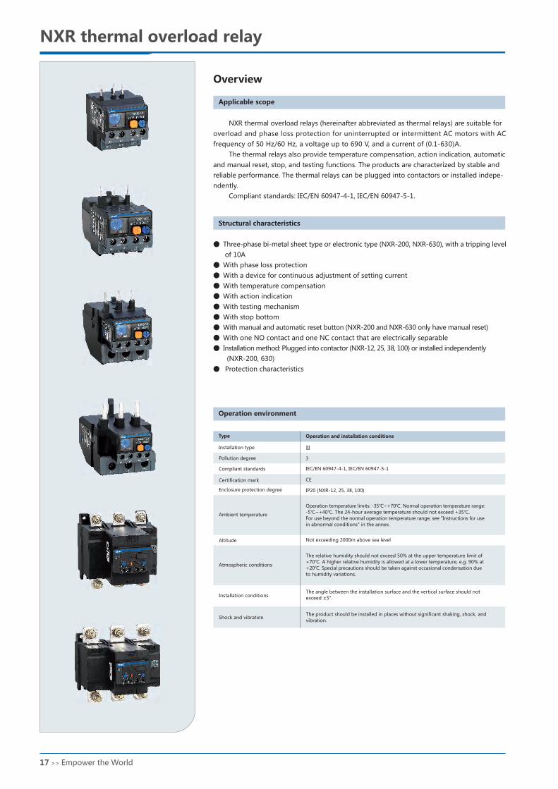
Overview
Applicable scope
NXR thermal overload relays (hereinafter abbreviated as thermal relays) are suitable for
overload and phase loss protection for uninterrupted or intermittent AC motors with AC
frequency of 50 Hz/60 Hz, a voltage up to 690 V, and a current of (0.1-630)A.
The thermal relays also provide temperature compensation, action indication, automatic
and manual reset, stop, and testing functions. The products are characterized by stable and
reliable performance. The thermal relays can be plugged into contactors or installed indepe-
ndently.
Compliant standards: IEC/EN 60947-4-1, IEC/EN 60947-5-1.
Structural characteristics
Operation environment
Type
Installation type
Pollution degree
Compliant standards
Certification mark
Enclosure protection degree
Ambient temperature
Altitude
Atmospheric conditions
Installation conditions
Shock and vibration
Operation and installation conditions
Operation temperature limits: -35℃~+70℃. Normal operation temperature range:
-5℃~+40℃. The 24-hour average temperature should not exceed +35℃.
For use beyond the normal operation temperature range, see "Instructions for use
in abnormal conditions" in the annex.
Not exceeding 2000m above sea level
The relative humidity should not exceed 50% at the upper temperature limit of
+70℃. A higher relative humidity is allowed at a lower temperature, e.g. 90% at
+20℃. Special precautions should be taken against occasional condensation due
to humidity variations.
The angle between the installation surface and the vertical surface should not
exceed ±5°.
The product should be installed in places without significant shaking, shock, and
vibration.
● Three-phase bi-metal sheet type or electronic type (NXR-200, NXR-630), with a tripping level
of 10A
● With phase loss protection
● With a device for continuous adjustment of setting current
● With temperature compensation
● With action indication
● With testing mechanism
● With stop bottom
● With manual and automatic reset button (NXR-200 and NXR-630 only have manual reset)
● With one NO contact and one NC contact that are electrically separable
● Installation method: Plugged into contactor (NXR-12, 25, 38, 100) or installed independently
(NXR-200, 630)
● Protection characteristics
Ⅲ
3
IEC/EN 60947-4-1, IEC/EN 60947-5-1
CE
IP20 (NXR-12, 25, 38, 100)
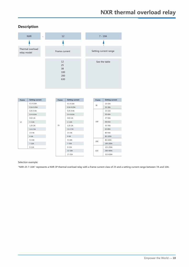
Description
Thermal overload
relay modelFrame current Setting current range
See the table
Selection example:
"NXR-25 7-10A" represents a NXR 3P thermal overload relay with a frame current class of 25 and a setting current range between 7A and 10A.
12
0.1-0.16A
0.16-0.25A
0.25-0.4A
0.4-0.63A
0.63-1A
1-1.6A
1.25-2A
1.6-2.5A
2.5-4A
4-6A
5.5-8A
7-10A
9-12A
Frame Setting current
0.1-0.16A
25
0.16-0.25A
0.25-0.4A
0.4-0.63A
0.63-1A
1-1.6A
1.25-2A
1.6-2.5A
2.5-4A
4-6A
5.5-8A
7-10A
9-13A
12-18A
17-25A
Frame Setting current
315-630A
3823-32A
30-38A
100
23-32A
30-40A
37-50A
48-65A
55-70A
63-80A
80-93A
80-100A
200
630
80-160A
100-200A
125-250A
200-400A
Frame Setting current
17 >> the World Empower Empower the World >> 18
NXR 7-10A12
12
25
38
100
200
630
NXR thermal overload relay NXR thermal overload relay
Overview
Applicable scope
NXR thermal overload relays (hereinafter abbreviated as thermal relays) are suitable for
overload and phase loss protection for uninterrupted or intermittent AC motors with AC
frequency of 50 Hz/60 Hz, a voltage up to 690 V, and a current of (0.1-630)A.
The thermal relays also provide temperature compensation, action indication, automatic
and manual reset, stop, and testing functions. The products are characterized by stable and
reliable performance. The thermal relays can be plugged into contactors or installed indepe-
ndently.
Compliant standards: IEC/EN 60947-4-1, IEC/EN 60947-5-1.
Structural characteristics
Operation environment
Type
Installation type
Pollution degree
Compliant standards
Certification mark
Enclosure protection degree
Ambient temperature
Altitude
Atmospheric conditions
Installation conditions
Shock and vibration
Operation and installation conditions
Operation temperature limits: -35℃~+70℃. Normal operation temperature range:
-5℃~+40℃. The 24-hour average temperature should not exceed +35℃.
For use beyond the normal operation temperature range, see "Instructions for use
in abnormal conditions" in the annex.
Not exceeding 2000m above sea level
The relative humidity should not exceed 50% at the upper temperature limit of
+70℃. A higher relative humidity is allowed at a lower temperature, e.g. 90% at
+20℃. Special precautions should be taken against occasional condensation due
to humidity variations.
The angle between the installation surface and the vertical surface should not
exceed ±5°.
The product should be installed in places without significant shaking, shock, and
vibration.
● Three-phase bi-metal sheet type or electronic type (NXR-200, NXR-630), with a tripping level
of 10A
● With phase loss protection
● With a device for continuous adjustment of setting current
● With temperature compensation
● With action indication
● With testing mechanism
● With stop bottom
● With manual and automatic reset button (NXR-200 and NXR-630 only have manual reset)
● With one NO contact and one NC contact that are electrically separable
● Installation method: Plugged into contactor (NXR-12, 25, 38, 100) or installed independently
(NXR-200, 630)
● Protection characteristics
Ⅲ
3
IEC/EN 60947-4-1, IEC/EN 60947-5-1
CE
IP20 (NXR-12, 25, 38, 100)
Description
Thermal overload
relay modelFrame current Setting current range
See the table
Selection example:
"NXR-25 7-10A" represents a NXR 3P thermal overload relay with a frame current class of 25 and a setting current range between 7A and 10A.
12
0.1-0.16A
0.16-0.25A
0.25-0.4A
0.4-0.63A
0.63-1A
1-1.6A
1.25-2A
1.6-2.5A
2.5-4A
4-6A
5.5-8A
7-10A
9-12A
Frame Setting current
0.1-0.16A
25
0.16-0.25A
0.25-0.4A
0.4-0.63A
0.63-1A
1-1.6A
1.25-2A
1.6-2.5A
2.5-4A
4-6A
5.5-8A
7-10A
9-13A
12-18A
17-25A
Frame Setting current
315-630A
3823-32A
30-38A
100
23-32A
30-40A
37-50A
48-65A
55-70A
63-80A
80-93A
80-100A
200
630
80-160A
100-200A
125-250A
200-400A
Frame Setting current
17 >> the World Empower Empower the World >> 18
23~32
30~40
37~50
48~65
55~70
63~80
80~93
80~100
63
80
23~32
30~38
63
100
100
100
125
125
160
160
80~160
125~200
315
315
125~250
200~400
315~630
800
800
800
gG
2
2
2
2
4
4
6
6
10
16
20
20
25
2
2
2
2
4
4
6
6
10
16
20
20
25
35
50
0.1~0.16
0.16~0.25
0.25~0.4
0.4~0.63
0.63~1
1~1.6
1.25~2
1.6~2.5
2.5~4
4~6
5.5~8
7~10
9~12
0.1~0.16
0.16~0.25
0.25~0.4
0.4~0.63
0.63~1
1~1.6
1.25~2
1.6~2.5
2.5~4
4~6
5.5~8
7~10
9~13
12~18
17~25
NXR-25
NXR-38
NXR-100
NXR-200
NXR-630
NXR-12NXC-06M, 09M, 12M
NXC-06, 09, 12, 16, 18, 22, 25, 32, 38
NXC-120, 160, 185, 225
NXC-225, 265, 330, 400, 500, 630
120
100
80
60
40
20
1086
4
2
1
40
20
10
86
4
2
1
min
s
0.8 11.2 1.5 2 3 4 5 6 7 8 9 10
NXR-25
25
690
NXR-100
100
690
NXR-200
200
690
NXR-630
630
690
NXR-12
12
690
NXR-38
38
690
Yes
Yes
Yes
Yes
Yes
Yes
Plugged
1NO+1NC
1.5
0.2
1~6
M4
0.8
1~2.5
M3.5
1.7
Yes
Yes
Yes
Yes
Yes
Yes
Plugged
1NO+1NC
1.5
0.2
4~35
M10
0.8
1~2.5
M3.5
10
Yes
Manual
Yes
Yes
Yes
Yes
Independent
1NO+1NC
1.5
0.2
25~95
M8
1.2
1~2.5
M3.5
10
Yes
Manual
Yes
Yes
Yes
Yes
Independent
1NO+1NC
1.5
0.2
50~2×185
M10
1.2
1~2.5
M3.5
20
Yes
Yes
Yes
Yes
Yes
Yes
Plugged
1NO+1NC
1.5
0.2
1~4
M3.5
0.8
1~2.5
M3.5
1.2
Yes
Yes
Yes
Yes
Yes
Yes
Plugged
1NO+1NC
1.5
0.2
4~10
M4
0.8
1~2.5
M3.5
1.7
6000 6000 6000 60006000 6000
- -IP20 IP20 IP20 IP20
NXC-25, 32, 38
NXC-40, 50, 65, 75, 85, 100
NXR thermal overload relay NXR thermal overload relay
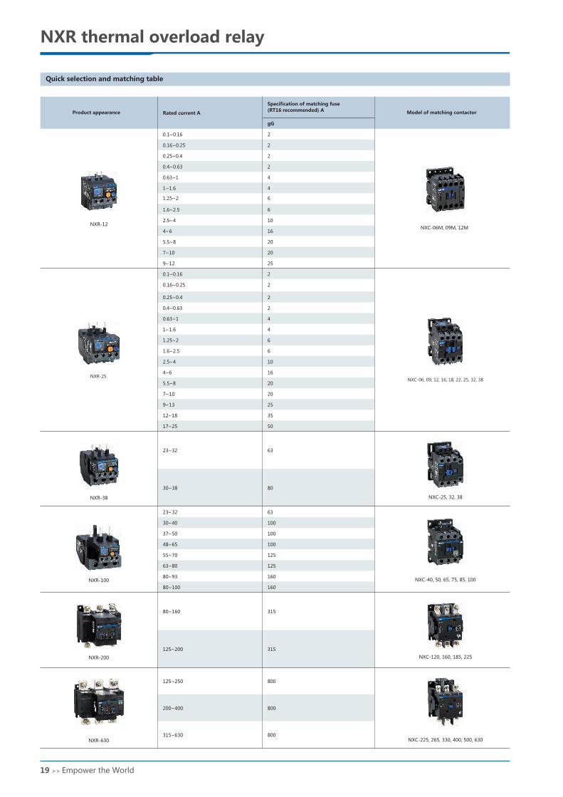
Quick selection and matching table
Product appearance Rated current A
Specification of matching fuse
(RT16 recommended) A Model of matching contactor
Parameters
Item
Current level
Rated insulation voltage V
Rated impulse withstand voltage V
Enclosure protection degree
Phase loss protection
Manual and automatic reset
Temperature compensation
Trip indication
Test button
Stop button
Integrated auxiliary contact
AC-15 rated current A380V/400V/415V
DC-13 220V rated current A
Conductor
cross
section 2mm
Main
circuit
Auxiliary
circuit
Single-core or stranded wire
Wiring screw
Tightening torque (N·m)
Single-core or stranded wire
Wiring screw
Tightening torque (N·m)
Protection characteristics
Item
Overload protection
Phase loss protection
No. Multiples of setting current
Any two phases The other phase
Action time
Without action in 2 hours
Act within 2 hours
Act within 2 minutes
Without action in 2 hours
Act within 2 hours
Test conditions
Start from cold state
Start from hot state (after No. 1)
Start after thermal equilibrium is reached under
setting current
Start from cold state
Start from cold state
Start from hot state (after No. 5)
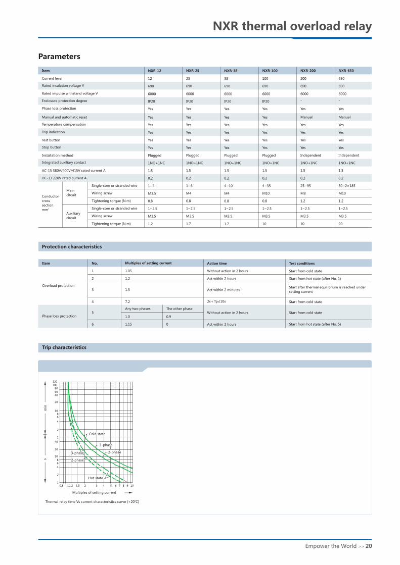
Trip characteristics
Multiples of setting current
Thermal relay time Vs current characteristics curve (+20℃)
Installation method
2s<Tp≤10s
0.9
0
1.05
1.2
1.5
7.2
1.0
1.15
1
2
3
4
5
6
Cold state
3-phase
2-phase3-phase
2-phase
Hot state
19 >> the World Empower Empower the World >> 20
23~32
30~40
37~50
48~65
55~70
63~80
80~93
80~100
63
80
23~32
30~38
63
100
100
100
125
125
160
160
80~160
125~200
315
315
125~250
200~400
315~630
800
800
800
gG
2
2
2
2
4
4
6
6
10
16
20
20
25
2
2
2
2
4
4
6
6
10
16
20
20
25
35
50
0.1~0.16
0.16~0.25
0.25~0.4
0.4~0.63
0.63~1
1~1.6
1.25~2
1.6~2.5
2.5~4
4~6
5.5~8
7~10
9~12
0.1~0.16
0.16~0.25
0.25~0.4
0.4~0.63
0.63~1
1~1.6
1.25~2
1.6~2.5
2.5~4
4~6
5.5~8
7~10
9~13
12~18
17~25
NXR-25
NXR-38
NXR-100
NXR-200
NXR-630
NXR-12NXC-06M, 09M, 12M
NXC-06, 09, 12, 16, 18, 22, 25, 32, 38
NXC-120, 160, 185, 225
NXC-225, 265, 330, 400, 500, 630
120
100
80
60
40
20
1086
4
2
1
40
20
10
86
4
2
1
min
s
0.8 11.2 1.5 2 3 4 5 6 7 8 9 10
NXR-25
25
690
NXR-100
100
690
NXR-200
200
690
NXR-630
630
690
NXR-12
12
690
NXR-38
38
690
Yes
Yes
Yes
Yes
Yes
Yes
Plugged
1NO+1NC
1.5
0.2
1~6
M4
0.8
1~2.5
M3.5
1.7
Yes
Yes
Yes
Yes
Yes
Yes
Plugged
1NO+1NC
1.5
0.2
4~35
M10
0.8
1~2.5
M3.5
10
Yes
Manual
Yes
Yes
Yes
Yes
Independent
1NO+1NC
1.5
0.2
25~95
M8
1.2
1~2.5
M3.5
10
Yes
Manual
Yes
Yes
Yes
Yes
Independent
1NO+1NC
1.5
0.2
50~2×185
M10
1.2
1~2.5
M3.5
20
Yes
Yes
Yes
Yes
Yes
Yes
Plugged
1NO+1NC
1.5
0.2
1~4
M3.5
0.8
1~2.5
M3.5
1.2
Yes
Yes
Yes
Yes
Yes
Yes
Plugged
1NO+1NC
1.5
0.2
4~10
M4
0.8
1~2.5
M3.5
1.7
6000 6000 6000 60006000 6000
- -IP20 IP20 IP20 IP20
NXC-25, 32, 38
NXC-40, 50, 65, 75, 85, 100
NXR thermal overload relay NXR thermal overload relay
Quick selection and matching table
Product appearance Rated current A
Specification of matching fuse
(RT16 recommended) A Model of matching contactor
Parameters
Item
Current level
Rated insulation voltage V
Rated impulse withstand voltage V
Enclosure protection degree
Phase loss protection
Manual and automatic reset
Temperature compensation
Trip indication
Test button
Stop button
Integrated auxiliary contact
AC-15 rated current A380V/400V/415V
DC-13 220V rated current A
Conductor
cross
section 2mm
Main
circuit
Auxiliary
circuit
Single-core or stranded wire
Wiring screw
Tightening torque (N·m)
Single-core or stranded wire
Wiring screw
Tightening torque (N·m)
Protection characteristics
Item
Overload protection
Phase loss protection
No. Multiples of setting current
Any two phases The other phase
Action time
Without action in 2 hours
Act within 2 hours
Act within 2 minutes
Without action in 2 hours
Act within 2 hours
Test conditions
Start from cold state
Start from hot state (after No. 1)
Start after thermal equilibrium is reached under
setting current
Start from cold state
Start from cold state
Start from hot state (after No. 5)
Trip characteristics
Multiples of setting current
Thermal relay time Vs current characteristics curve (+20℃)
Installation method
2s<Tp≤10s
0.9
0
1.05
1.2
1.5
7.2
1.0
1.15
1
2
3
4
5
6
Cold state
3-phase
2-phase3-phase
2-phase
Hot state
19 >> the World Empower Empower the World >> 20
NXR-25
NXR-38
NXR-25
STOP RESET
67m
ax
TEST
911 13
A
45max
2/T1
NCNO
T A
H
98 97 96 95
4/T2 6/T3
94max
82m
ax
94max
H
A T
NXR-38
STOP RESET
55max
2/T1
NCNO98 97 96 95
4/T2 6/T3
NXR-100
83m
ax
118max
NCNO
T A
H
98 97 96 95
72max
NXR-100
STOP RESET
2/T1 4/T2 6/T3
TEST
TEST
23
80
26
90
32
100
A
A
29
NXR-12
68max
T A
HTEST
911 12
A NXR-12
STOP RESET
10
45max
73m
ax
1/L11/L1 3/L2
98 97 96 95NCNO
2/T1 4/T2 6/T3
5/L3
NXR thermal overload relay NXR thermal overload relay
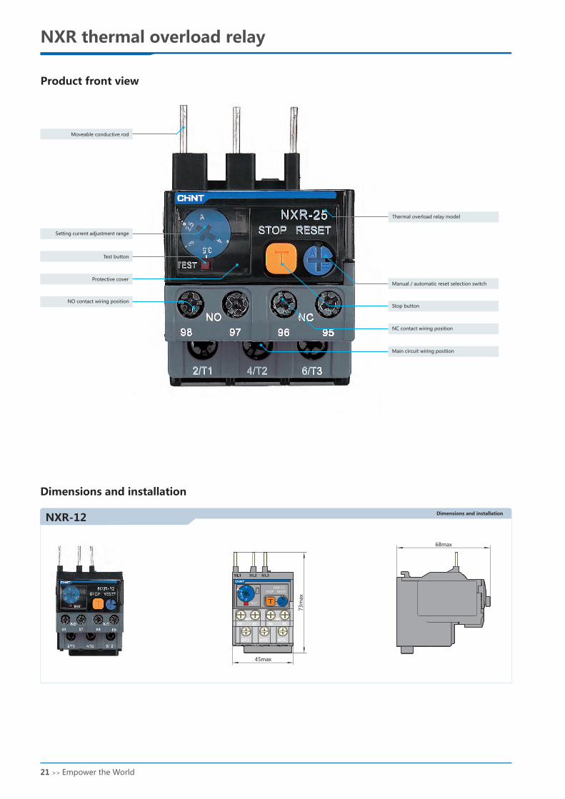
Product front view
Moveable conductive rod
Setting current adjustment range
Test button
Protective cover
NO contact wiring position
Thermal overload relay model
Manual / automatic reset selection switch
Stop button
NC contact wiring position
Main circuit wiring position
Dimensions and installation
Dimensions and installation Dimensions and installation
Dimensions and installation
Dimensions and installation
21 >> the World Empower Empower the World >> 22
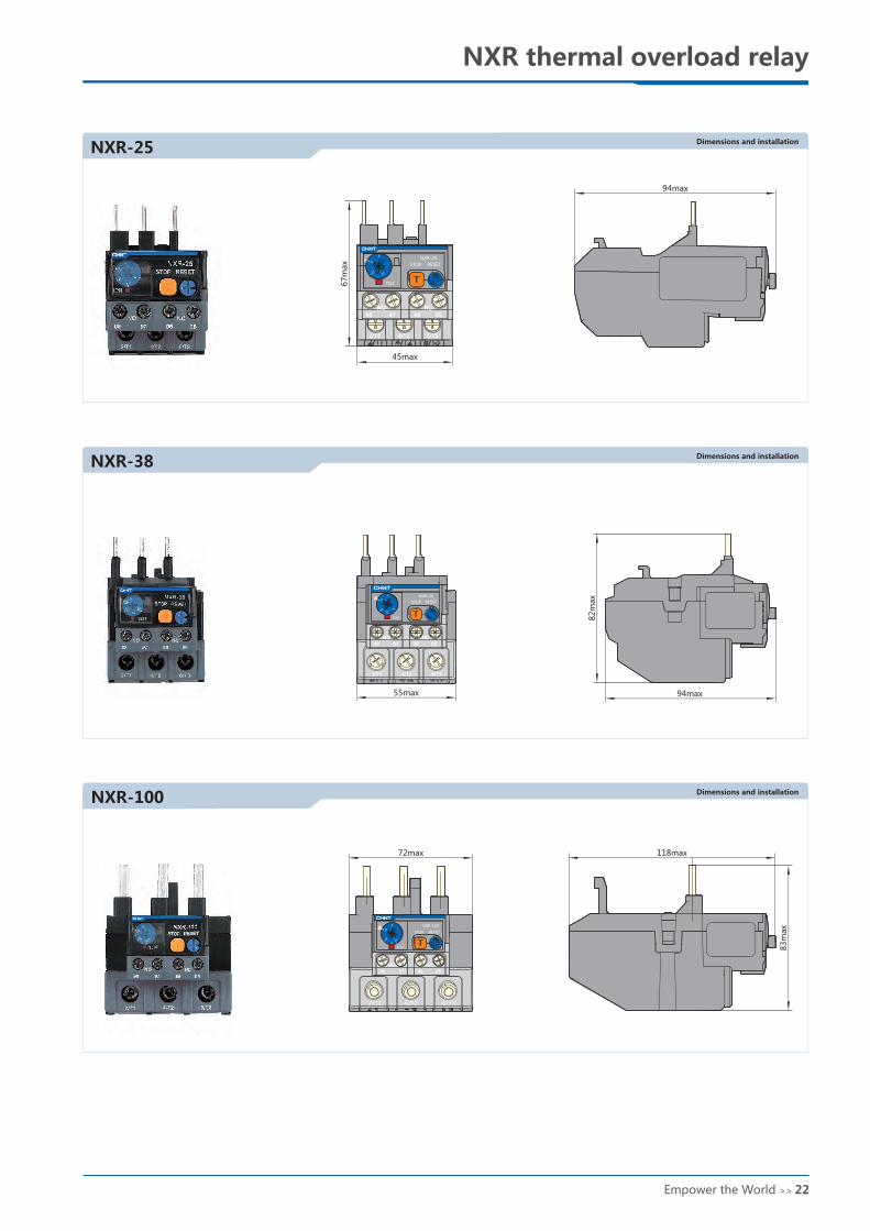
NXR-25
NXR-38
NXR-25
STOP RESET
67m
ax
TEST
911 13
A
45max
2/T1
NCNO
T A
H
98 97 96 95
4/T2 6/T3
94max
82m
ax
94max
H
A T
NXR-38
STOP RESET
55max
2/T1
NCNO98 97 96 95
4/T2 6/T3
NXR-100 83m
ax
118max
NCNO
T A
H
98 97 96 95
72max
NXR-100
STOP RESET
2/T1 4/T2 6/T3
TEST
TEST
23
80
26
90
32
100
A
A
29
NXR-12
68max
T A
H
TEST
911 12
A NXR-12
STOP RESET
10
45max
73m
ax
1/L11/L1 3/L2
98 97 96 95NCNO
2/T1 4/T2 6/T3
5/L3
NXR thermal overload relay NXR thermal overload relay
Product front view
Moveable conductive rod
Setting current adjustment range
Test button
Protective cover
NO contact wiring position
Thermal overload relay model
Manual / automatic reset selection switch
Stop button
NC contact wiring position
Main circuit wiring position
Dimensions and installation
Dimensions and installation Dimensions and installation
Dimensions and installation
Dimensions and installation
21 >> the World Empower Empower the World >> 22
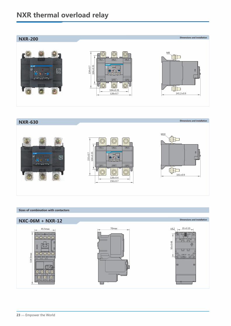
NXR-200
NXR-630
NXC-06M + NXR-12
M8
141.2±0.9
M10
161±0.9
NC NO989796951
04±
0.3
5
128±0.4
155±
0.7
156±0.7
1/L1
NXR
-630
3/L2
280 320
360
240
200 400Stop
Test
Reset
2/T1 4/T2 6/T3
5/L3
NC NO98979695
104±0.35
128±0.7104±
0.3
5
134±
0.7
1/L1
NXR-200
140 160
180
120
100 200Stop
Test
Reset
3/L2 5/L3
2/T1 4/T2 6/T3
70max 35±0.35
50±
0.4
8
43
PA
35X50 M4mm
1.38X1.97 inch
45.5max
114.5
max
1/L1 3/L2 5/L3
A
H
98 97 96 95
2/T1 4/T2 6/T32/T1 4/T2 6/T3
T
N0 NC
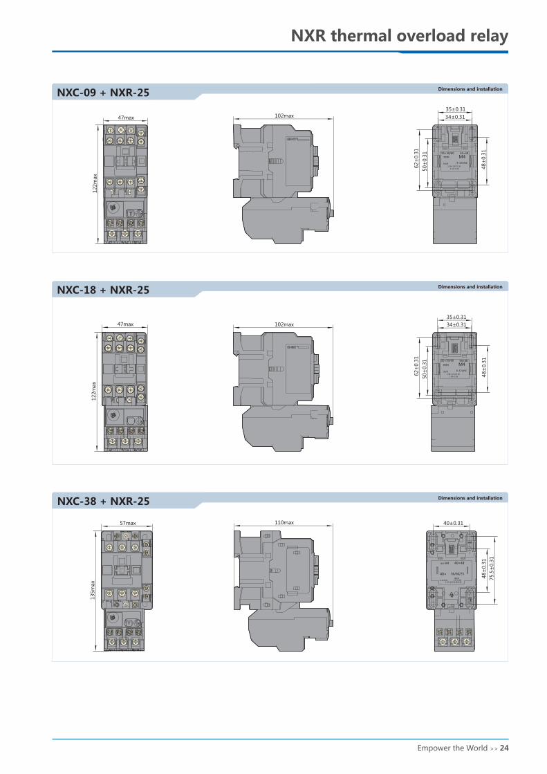
NXC-09 + NXR-25
NXC-18 + NXR-25
102max
R
H
A
122m
ax
47max
T
34±0.31
35±0.31
48±
0.3
1
50±
0.3
1
62±
0.3
1
35×50/60
mm M434×48
inch 8-32UNC
1.38×1.97/2.36
1.34×1.89
AT
122m
ax
47max
H
102max
R
34±0.31
48±
0.3
1
35±0.31
50±
0.3
1
62±
0.3
1
35×50/60
mm M434×48
inch 8-32UNC
1.38×1.97/2.36
1.34×1.89
NXC-38 + NXR-25
H
AT
57max
135m
ax
110max
INCH
40±0.31
75.5
±0.3
1
48±
0.3
1
40×48MM M4
40× 50/60/75
8-32UNC 1.57×1.891.57×1.97/2.36/2.95
NXR thermal overload relay NXR thermal overload relay
Sizes of combination with contactors
Dimensions and installation Dimensions and installation
Dimensions and installation
Dimensions and installation
Dimensions and installation
Dimensions and installation
4.2
23 >> the World Empower Empower the World >> 24
NXR-200
NXR-630
NXC-06M + NXR-12
M8
141.2±0.9
M10
161±0.9
NC NO989796951
04±
0.3
5
128±0.4
155±
0.7
156±0.7
1/L1
NXR
-630
3/L2
280 320
360
240
200 400Stop
Test
Reset
2/T1 4/T2 6/T3
5/L3
NC NO98979695
104±0.35
128±0.7
104±
0.3
5
134±
0.7
1/L1
NXR-200
140 160
180
120
100 200Stop
Test
Reset
3/L2 5/L3
2/T1 4/T2 6/T3
70max 35±0.35
50±
0.4
8
43
PA
35X50 M4mm
1.38X1.97 inch
45.5max
114.5
max
1/L1 3/L2 5/L3
A
H
98 97 96 95
2/T1 4/T2 6/T32/T1 4/T2 6/T3
T
N0 NC
NXC-09 + NXR-25
NXC-18 + NXR-25
102max
R
H
A
122m
ax
47max
T
34±0.31
35±0.31
48±
0.3
1
50±
0.3
1
62±
0.3
1
35×50/60
mm M434×48
inch 8-32UNC
1.38×1.97/2.36
1.34×1.89
AT
122m
ax
47max
H
102max
R
34±0.31
48±
0.3
1
35±0.31
50±
0.3
1
62±
0.3
1
35×50/60
mm M434×48
inch 8-32UNC
1.38×1.97/2.36
1.34×1.89
NXC-38 + NXR-25
H
AT
57max
135m
ax
110max
INCH
40±0.31
75.5
±0.3
1
48±
0.3
1
40×48MM M4
40× 50/60/75
8-32UNC 1.57×1.891.57×1.97/2.36/2.95
NXR thermal overload relay NXR thermal overload relay
Sizes of combination with contactors
Dimensions and installation Dimensions and installation
Dimensions and installation
Dimensions and installation
Dimensions and installation
Dimensions and installation
4.2
23 >> the World Empower Empower the World >> 24

+70℃
NXR-12, 25, 38, 100
NXC-38 + NXR-38
NXC-40 + NXR-100
NXC-75 + NXR-100
102max
147m
ax
57maxH
AT
75.5
±0.3
1
48±
0.3
1
40±0.31
INCH
40×48MM M4
40× 50/60/75
8-32UNC 1.57×1.891.57×1.97/2.36/2.95
124max
64±0.3
40±0.3
PA
43
79max
NXC-40
1/L1 3/L2 5/L3
2/T1 4/T2 6/T3
21NC
13NO
14NO
22NC
179m
ax
T A
H
R
131max
105±
0.5
7
40±0.28
T A
H
87max
187m
ax
1.05
1.4
0.9
1.2
9795
9896
1/L1 3/L2 5/L3
2/T1 4/T2 6/T3
9795
9896
1/L1 3/L2 5/L3
2/T1 4/T2 6/T3
105±
0.3
NXR-12~100 NXR-200~630
NXR thermal overload relay NXR thermal overload relay
Dimensions and installation
Dimensions and installation
Dimensions and installation
Wiring diagrams
Annex I: Instructions for use in abnormal conditions
●
●
●
IEC/EN 60947-4-1
impact on their performance.
At an operation temperature higher than +40℃, the tolerable temperature rise of products needs to be reduced. The rated operation current should
be adjusted to prevent product damage, shortened service life, lower reliability, or impact on action characteristics.At a temperature lower than -5℃,
impact of changes to the heat dissipation system on the action characteristics of the products should be considered.
The temperature compensation coefficients at an ambient temperature higher than +40℃ and lower than -5℃ are given below. The compensation
coefficients corresponding to -35℃ and +70℃ environments are given in the table below. No corrections are required for NXR-200 and NXR-630.
standard defines normal operation temperature range for products. Use of products in the normal range will not cause significant
Operation ambient temperature
Temperature compensation coefficients for NXR-12, 25, 38, 100Multiple of stable current
Multiple of trip current
Temperature compensation curve
-40 -30 -20 -10 0 10 20 30 40 50 60
0.9
1.0
1.1
1.2
1.3
1.4
1.5
70 80
0.8
Setting multiple of the overload current
Ambient temperature ℃
-35℃
25 >> the World Empower Empower the World >> 26
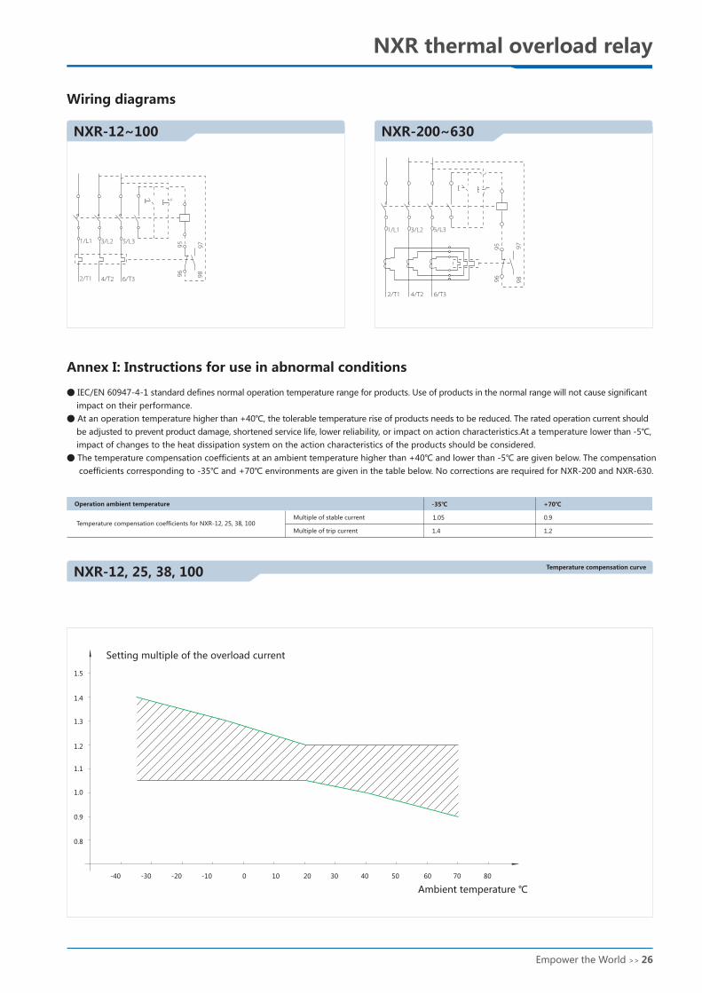
+70℃
NXR-12, 25, 38, 100
NXC-38 + NXR-38
NXC-40 + NXR-100
NXC-75 + NXR-100
102max
147m
ax
57max
H
AT
75.5
±0.3
1
48±
0.3
1
40±0.31
INCH
40×48MM M4
40× 50/60/75
8-32UNC 1.57×1.891.57×1.97/2.36/2.95
124max
64±0.3
40±0.3
PA
43
79max
NXC-40
1/L1 3/L2 5/L3
2/T1 4/T2 6/T3
21NC
13NO
14NO
22NC
179m
ax
T A
H
R
131max
105±
0.5
7
40±0.28
T A
H
87max
187m
ax
1.05
1.4
0.9
1.2
9795
9896
1/L1 3/L2 5/L3
2/T1 4/T2 6/T3
9795
9896
1/L1 3/L2 5/L3
2/T1 4/T2 6/T3
105±
0.3
NXR-12~100 NXR-200~630
NXR thermal overload relay NXR thermal overload relay
Dimensions and installation
Dimensions and installation
Dimensions and installation
Wiring diagrams
Annex I: Instructions for use in abnormal conditions
●
●
●
IEC/EN 60947-4-1
impact on their performance.
At an operation temperature higher than +40℃, the tolerable temperature rise of products needs to be reduced. The rated operation current should
be adjusted to prevent product damage, shortened service life, lower reliability, or impact on action characteristics.At a temperature lower than -5℃,
impact of changes to the heat dissipation system on the action characteristics of the products should be considered.
The temperature compensation coefficients at an ambient temperature higher than +40℃ and lower than -5℃ are given below. The compensation
coefficients corresponding to -35℃ and +70℃ environments are given in the table below. No corrections are required for NXR-200 and NXR-630.
standard defines normal operation temperature range for products. Use of products in the normal range will not cause significant
Operation ambient temperature
Temperature compensation coefficients for NXR-12, 25, 38, 100Multiple of stable current
Multiple of trip current
Temperature compensation curve
-40 -30 -20 -10 0 10 20 30 40 50 60
0.9
1.0
1.1
1.2
1.3
1.4
1.5
70 80
0.8
Setting multiple of the overload current
Ambient temperature ℃
-35℃
25 >> the World Empower Empower the World >> 26