nvm express™: unlock the potential - flash memory summit€¦ · ... pcie add-in-card, sff-8639,...
TRANSCRIPT
Audio-Visual Sponsor
NVM Express™: Unlock the Potential
Forum A-11
Audio-Visual Sponsor
The Maturity of NVM Express™
Tom Lenny
Principal Program Manager
Seagate Technology
NVMe Organization
NVM Express is a scalable host controller
interface designed for Enterprise and Client SSDs
that utilize PCI Express® (PCIe®)
NVM Express work group transitioned to an
incorporated industry standards organization in
March 2014
More than 50 member companies
Go to www.nvmexpress.org for information on
how to join
Flash Memory Summit 2014
Santa Clara, CA
3
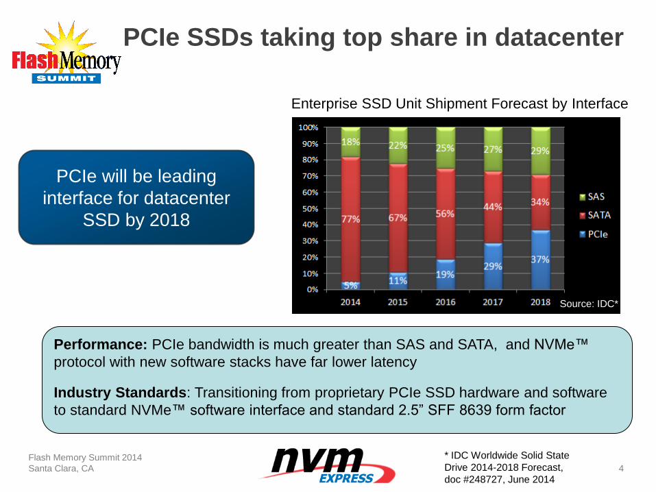
PCIe SSDs taking top share in datacenter
Flash Memory Summit 2014
Santa Clara, CA
4
PCIe will be leading
interface for datacenter
SSD by 2018
Performance: PCIe bandwidth is much greater than SAS and SATA, and NVMe™
protocol with new software stacks have far lower latency
Industry Standards: Transitioning from proprietary PCIe SSD hardware and software
to standard NVMe™ software interface and standard 2.5” SFF 8639 form factor
Enterprise SSD Unit Shipment Forecast by Interface
Source: IDC*
* IDC Worldwide Solid State
Drive 2014-2018 Forecast,
doc #248727, June 2014
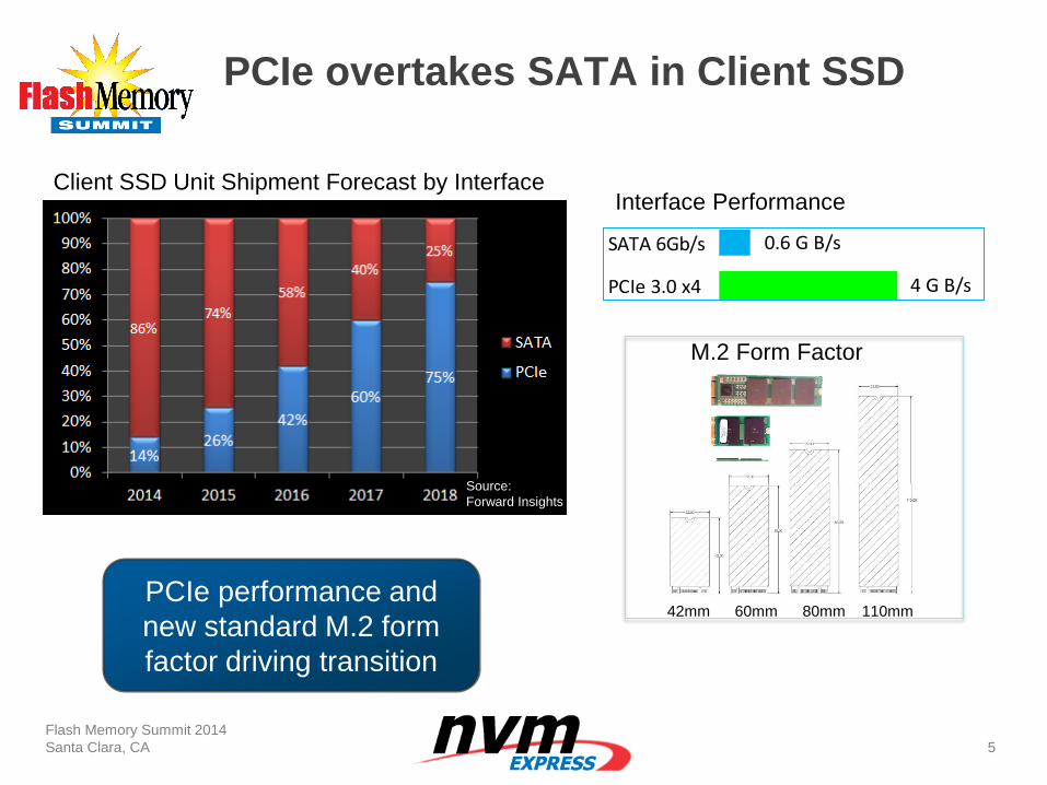
PCIe overtakes SATA in Client SSD
Flash Memory Summit 2014
Santa Clara, CA
5
42mm 60mm 80mm 110mm
M.2 Form Factor
SATA 6Gb/s
PCIe 3.0 x4
0.6 G B/s
4 G B/s
PCIe performance and
new standard M.2 form
factor driving transition
Client SSD Unit Shipment Forecast by Interface Interface Performance
Source:
Forward Insights
NVMe™ Interoperability
Flash Memory Summit 2014
Santa Clara, CA
6
• NVMe Organization along with UNH-IOL continue to
develop new compliance and interoperability tests to drive
for mature production devices with plug and play
experience
• 1st Plugfest, May 2013, had 11 participant companies
• 2nd Plugfest, February 2014, had 14 companies
• 3rd Plugfest scheduled for November 10-13, 2014 at UNH-IOL
• Register for plugfest:
www.iol.unh.edu/services/testing/NVMe/plugfest.php
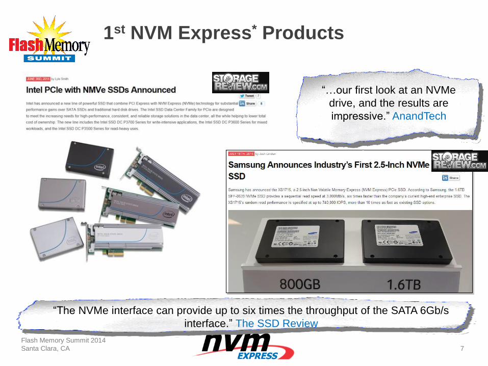
1st NVM Express* Products
Flash Memory Summit 2014
Santa Clara, CA
7
“…our first look at an NVMe
drive, and the results are
impressive.” AnandTech
“The NVMe interface can provide up to six times the throughput of the SATA 6Gb/s
interface.” The SSD Review
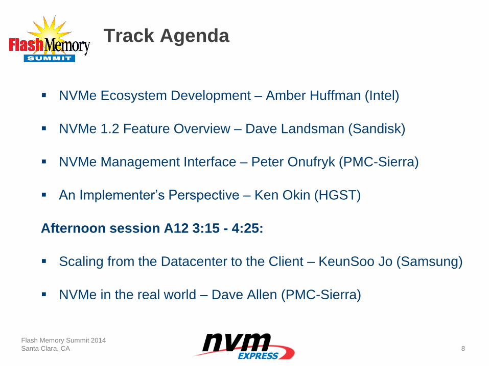
Track Agenda
NVMe Ecosystem Development – Amber Huffman (Intel)
NVMe 1.2 Feature Overview – Dave Landsman (Sandisk)
NVMe Management Interface – Peter Onufryk (PMC-Sierra)
An Implementer’s Perspective – Ken Okin (HGST)
Afternoon session A12 3:15 - 4:25:
Scaling from the Datacenter to the Client – KeunSoo Jo (Samsung)
NVMe in the real world – Dave Allen (PMC-Sierra)
Flash Memory Summit 2014
Santa Clara, CA
8
Audio-Visual Sponsor
NVM Express Ecosystem Development
Amber Huffman
Sr. Principal Engineer
Intel Corporation
Outline
Ecosystem Embrace of PCIe* Storage
NVM Express Overview
Features for Client and Datacenter
Native Driver Support for NVMe™
Form Factors and Connectors
Using Hot Plug with NVMe
Interoperability Program for NVMe
Flash Memory Summit 2014
Santa Clara, CA
10
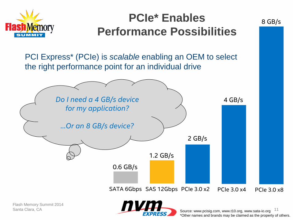
PCIe* Enables
Performance Possibilities
PCI Express* (PCIe) is scalable enabling an OEM to select
the right performance point for an individual drive
Flash Memory Summit 2014
Santa Clara, CA
11
PCIe 3.0 x4 PCIe 3.0 x8
4 GB/s
8 GB/s
PCIe 3.0 x2
2 GB/s
SAS 12Gbps
1.2 GB/s
SATA 6Gbps
0.6 GB/s
Do I need a 4 GB/s device for my application?
…Or an 8 GB/s device?
Source: www.pcisig.com, www.t10.org, www.sata-io.org
*Other names and brands may be claimed as the property of others.
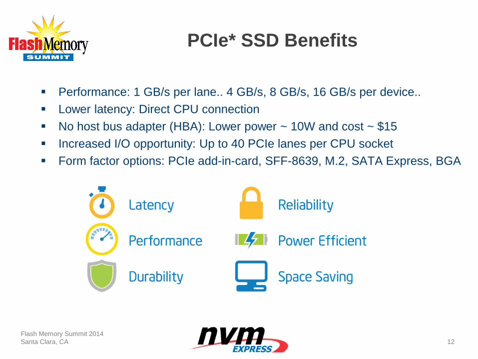
PCIe* SSD Benefits
Performance: 1 GB/s per lane.. 4 GB/s, 8 GB/s, 16 GB/s per device..
Lower latency: Direct CPU connection
No host bus adapter (HBA): Lower power ~ 10W and cost ~ $15
Increased I/O opportunity: Up to 40 PCIe lanes per CPU socket
Form factor options: PCIe add-in-card, SFF-8639, M.2, SATA Express, BGA
Flash Memory Summit 2014
Santa Clara, CA
12
NVM Express Overview
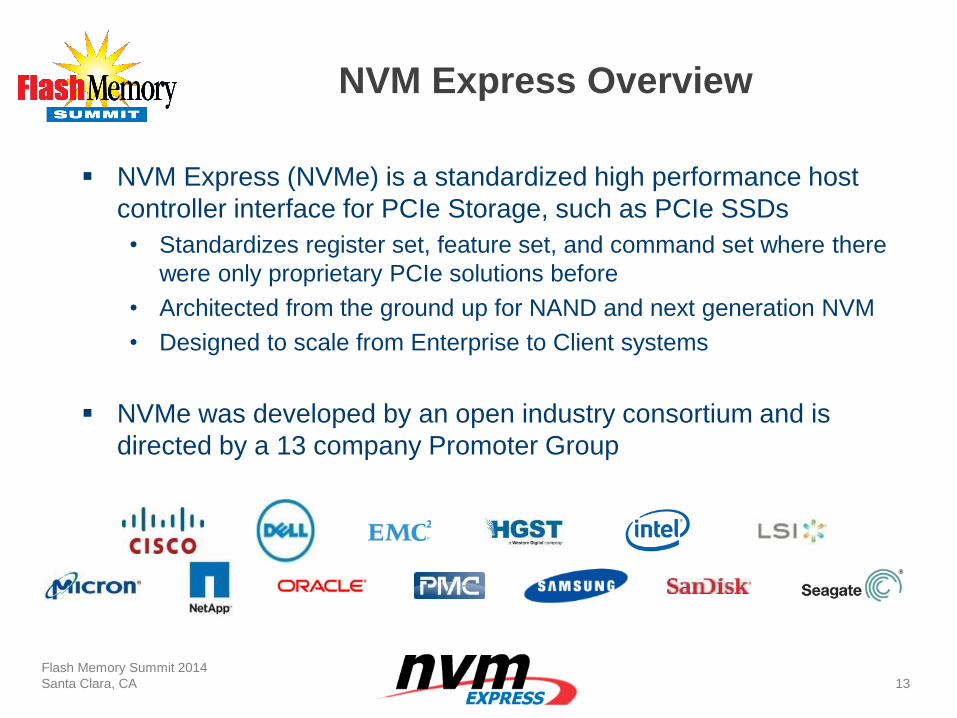
NVM Express (NVMe) is a standardized high performance host
controller interface for PCIe Storage, such as PCIe SSDs
• Standardizes register set, feature set, and command set where there
were only proprietary PCIe solutions before
• Architected from the ground up for NAND and next generation NVM
• Designed to scale from Enterprise to Client systems
NVMe was developed by an open industry consortium and is
directed by a 13 company Promoter Group
Flash Memory Summit 2014
Santa Clara, CA
13
Technical Basics of NVMe
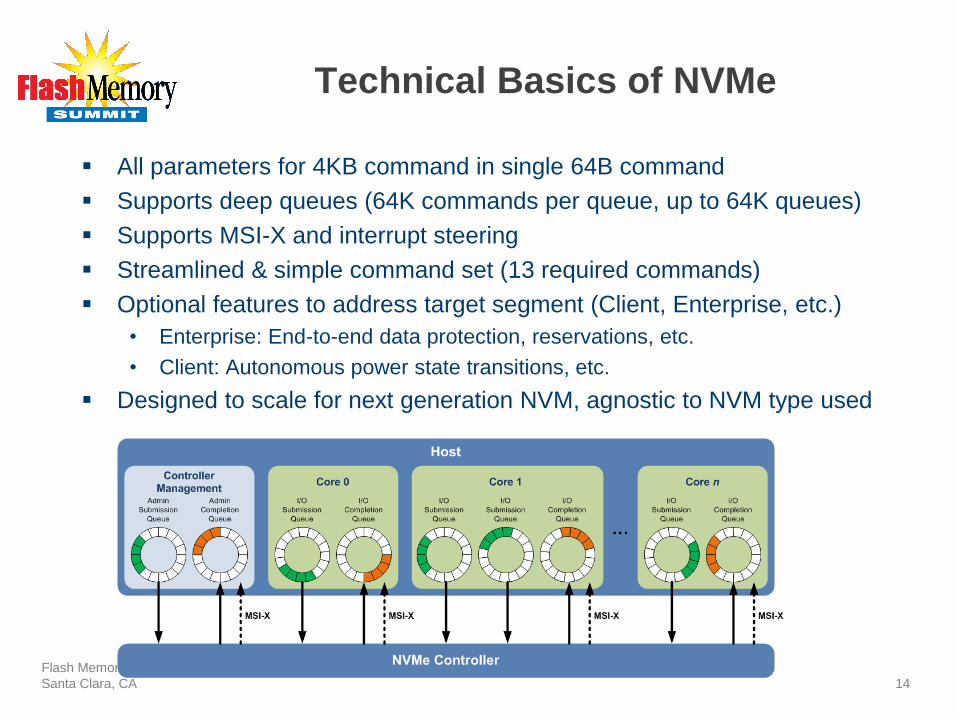
All parameters for 4KB command in single 64B command
Supports deep queues (64K commands per queue, up to 64K queues)
Supports MSI-X and interrupt steering
Streamlined & simple command set (13 required commands)
Optional features to address target segment (Client, Enterprise, etc.)
• Enterprise: End-to-end data protection, reservations, etc.
• Client: Autonomous power state transitions, etc.
Designed to scale for next generation NVM, agnostic to NVM type used
Flash Memory Summit 2014
Santa Clara, CA
14
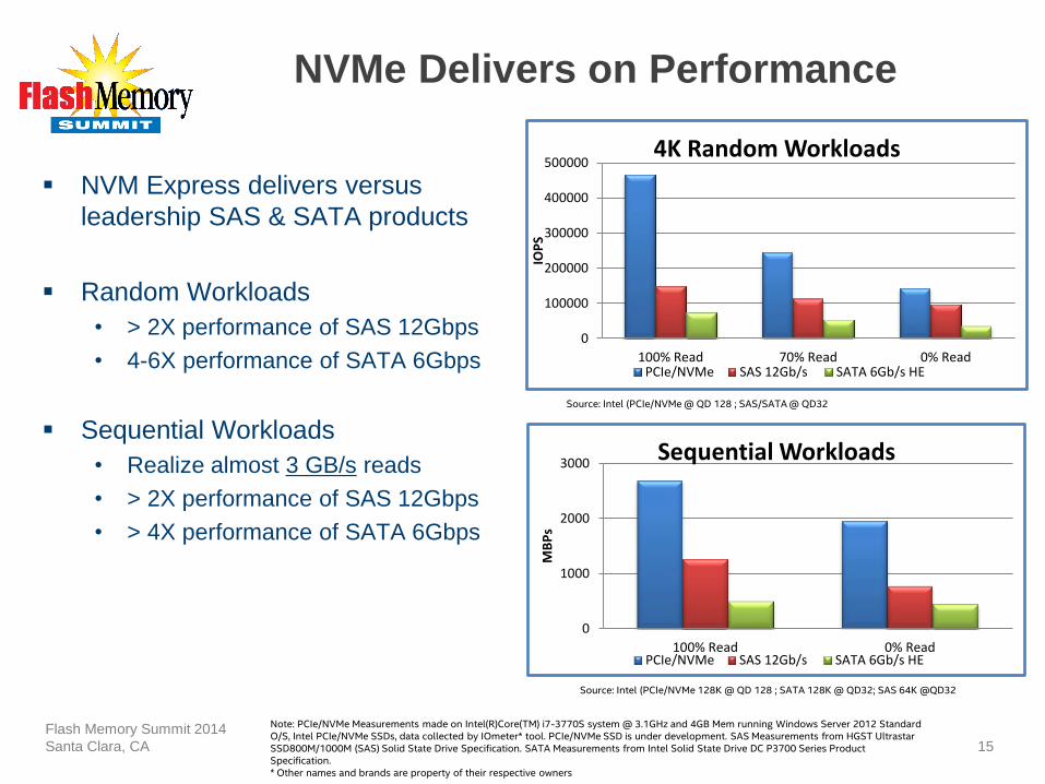
NVMe Delivers on Performance
NVM Express delivers versus
leadership SAS & SATA products
Random Workloads
• > 2X performance of SAS 12Gbps
• 4-6X performance of SATA 6Gbps
Sequential Workloads
• Realize almost 3 GB/s reads
• > 2X performance of SAS 12Gbps
• > 4X performance of SATA 6Gbps
Flash Memory Summit 2014
Santa Clara, CA
15
Source: Intel (PCIe/NVMe @ QD 128 ; SAS/SATA @ QD32
0
100000
200000
300000
400000
500000
100% Read 70% Read 0% Read
IOP
S
4K Random Workloads
PCIe/NVMe SAS 12Gb/s SATA 6Gb/s HE
Source: Intel (PCIe/NVMe 128K @ QD 128 ; SATA 128K @ QD32; SAS 64K @QD32
0
1000
2000
3000
100% Read 0% Read
MB
Ps
Sequential Workloads
PCIe/NVMe SAS 12Gb/s SATA 6Gb/s HE
Note: PCIe/NVMe Measurements made on Intel(R)Core(TM) i7-3770S system @ 3.1GHz and 4GB Mem running Windows Server 2012 Standard O/S, Intel PCIe/NVMe SSDs, data collected by IOmeter* tool. PCIe/NVMe SSD is under development. SAS Measurements from HGST Ultrastar SSD800M/1000M (SAS) Solid State Drive Specification. SATA Measurements from Intel Solid State Drive DC P3700 Series Product Specification. * Other names and brands are property of their respective owners
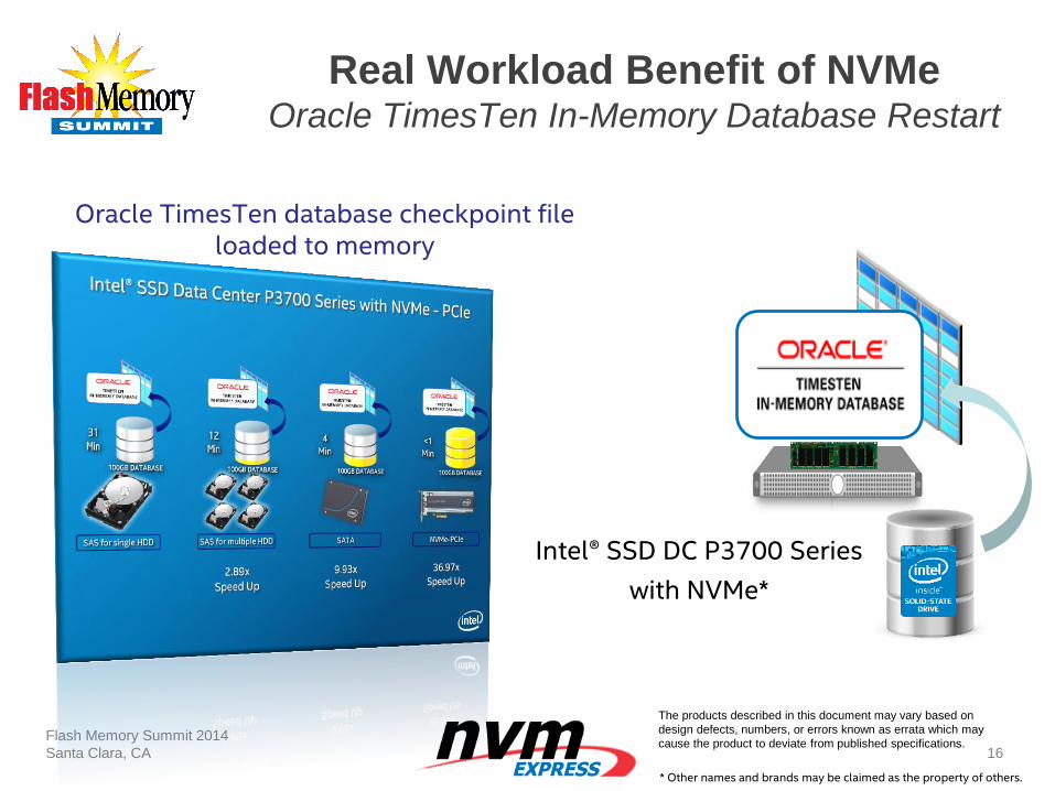
Real Workload Benefit of NVMe Oracle TimesTen In-Memory Database Restart
Flash Memory Summit 2014
Santa Clara, CA
16
Oracle TimesTen database checkpoint file loaded to memory
Intel® SSD DC P3700 Series
with NVMe*
The products described in this document may vary based on
design defects, numbers, or errors known as errata which may
cause the product to deviate from published specifications.
* Other names and brands may be claimed as the property of others.
NVMe Scales
from Client to Datacenter
NVMe allows devices to flexibly report capabilities
• Number of queues, number of power states, etc
NVMe features may be focused on Datacenter, on Client, or both
Flash Memory Summit 2014
Santa Clara, CA
18
How do you determine the NVMe features needed for your use case?
Different features, form factor, capacity, etc,
based on market segment targeted
Current Feature Guidance
Flash Memory Summit 2014
Santa Clara, CA
19
Feature Datacenter Guidance Client Guidance
Number of Queues 16 to 128 2 to 8
Number of Namespaces 1 to 16 (use case dependent) 1 to 4 (use case dependent)
Number of Power States 1 to 4 3 to 4
Arbitration Mechanism Weighted Round Robin with Urgent
Priority Class or Round Robin Round Robin
End-to-end Data Protection Yes No
Security Tunneling Yes Yes
Autonomous Power State
Transitions For small form factors Yes
Scatter/Gather List Yes for Storage Customers No
Reservations (and Dual Port) Yes for Storage Customers No
Revision 1.2 Feature Guidance
Flash Memory Summit 2014
Santa Clara, CA
20
Feature Datacenter Guidance Client Guidance
Namespace Management Yes (if multiple supported) Yes (if multiple supported)
Namespace Inventory Change
Notices Yes No
Temperature Threshold Yes Minimal support (e.g., 1 sensor)
Power State Enhancements
and Runtime D3 Entry/Exit No
Yes
Host Memory Buffer No Yes
Controller Memory Buffer Yes for Storage Customers No
Replay Protected Memory
Block No Yes for mobile oriented SKU
Command Effects Log for
NVMe Passthrough Support Yes Yes
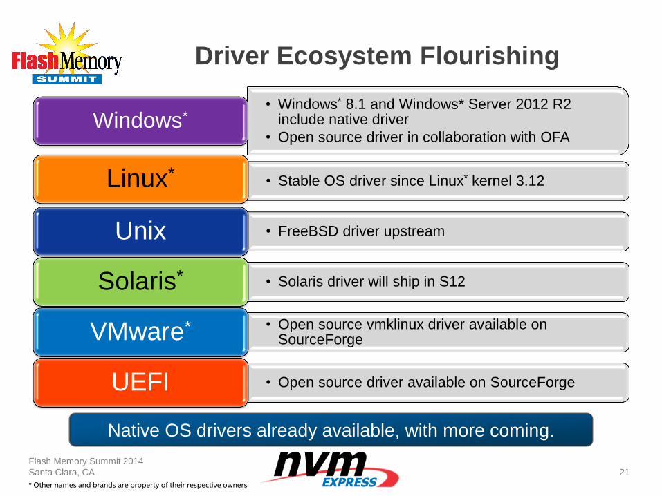
Driver Ecosystem Flourishing
Flash Memory Summit 2014
Santa Clara, CA
21
• Windows* 8.1 and Windows* Server 2012 R2 include native driver
• Open source driver in collaboration with OFA Windows*
• Stable OS driver since Linux* kernel 3.12 Linux*
• FreeBSD driver upstream Unix
• Solaris driver will ship in S12 Solaris*
• Open source vmklinux driver available on SourceForge VMware*
• Open source driver available on SourceForge UEFI
* Other names and brands are property of their respective owners
Native OS drivers already available, with more coming.
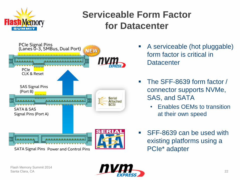
Serviceable Form Factor
for Datacenter
A serviceable (hot pluggable)
form factor is critical in
Datacenter
The SFF-8639 form factor /
connector supports NVMe,
SAS, and SATA
• Enables OEMs to transition
at their own speed
SFF-8639 can be used with
existing platforms using a
PCIe* adapter
Flash Memory Summit 2014
Santa Clara, CA
22
SATA Signal Pins Power and Control Pins
SATA & SAS Signal Pins (Port A)
SAS Signal Pins (Port B)
PCIe Signal Pins (Lanes 0-3, SMBus, Dual Port)
PCIe CLK & Reset
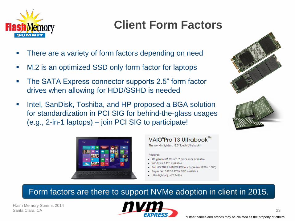
Client Form Factors
There are a variety of form factors depending on need
M.2 is an optimized SSD only form factor for laptops
The SATA Express connector supports 2.5” form factor
drives when allowing for HDD/SSHD is needed
Intel, SanDisk, Toshiba, and HP proposed a BGA solution
for standardization in PCI SIG for behind-the-glass usages
(e.g., 2-in-1 laptops) – join PCI SIG to participate!
Flash Memory Summit 2014
Santa Clara, CA
23
*
*Other names and brands may be claimed as the property of others.
Form factors are there to support NVMe adoption in client in 2015.
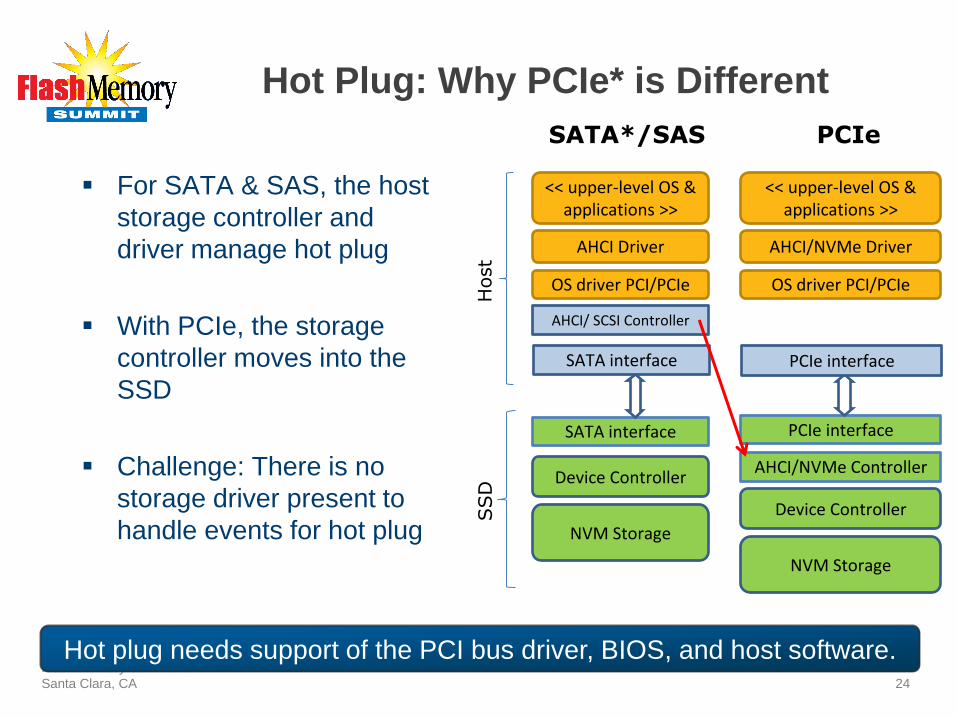
Hot Plug: Why PCIe* is Different
For SATA & SAS, the host
storage controller and
driver manage hot plug
With PCIe, the storage
controller moves into the
SSD
Challenge: There is no
storage driver present to
handle events for hot plug
Flash Memory Summit 2014
Santa Clara, CA
24
AHCI/ SCSI Controller
SATA interface
AHCI Driver
Device Controller
NVM Storage
OS driver PCI/PCIe
<< upper-level OS & applications >>
Host
SSD
SATA interface
AHCI/NVMe Controller
PCIe interface
AHCI/NVMe Driver
Device Controller
NVM Storage
OS driver PCI/PCIe
<< upper-level OS & applications >>
PCIe interface
SATA*/SAS PCIe
Hot plug needs support of the PCI bus driver, BIOS, and host software.
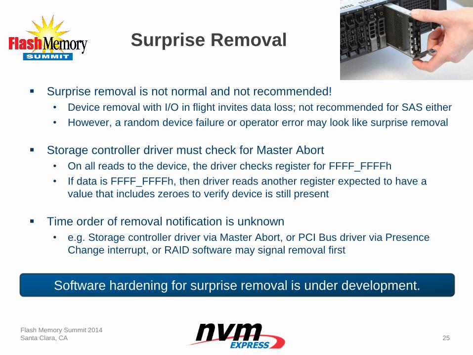
Surprise Removal
Surprise removal is not normal and not recommended!
• Device removal with I/O in flight invites data loss; not recommended for SAS either
• However, a random device failure or operator error may look like surprise removal
Storage controller driver must check for Master Abort
• On all reads to the device, the driver checks register for FFFF_FFFFh
• If data is FFFF_FFFFh, then driver reads another register expected to have a
value that includes zeroes to verify device is still present
Time order of removal notification is unknown
• e.g. Storage controller driver via Master Abort, or PCI Bus driver via Presence
Change interrupt, or RAID software may signal removal first
Flash Memory Summit 2014
Santa Clara, CA
25
Software hardening for surprise removal is under development.
Normal Hot Plug Use Cases
Hot Add & Remove are software managed events
• The operator takes explicit action, including software configuration
During boot, the system must prepare for hot plug:
• Configure PCI Express* Slot Capability registers
• Enable/register for hot plug events to higher level software (e.g., RAID)
• Pre-allocate slot resources (Bus IDs, interrupts, memory regions) using
ACPI*
No updates to host hardware (CPU/chipset) is needed
Flash Memory Summit 2014
Santa Clara, CA
26
Existing BIOS and Windows*/Linux* OS
are prepared to support PCIe hot plug today.
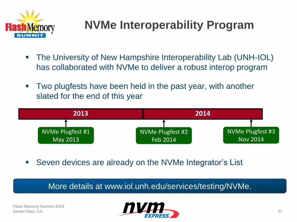
NVMe Interoperability Program
The University of New Hampshire Interoperability Lab (UNH-IOL)
has collaborated with NVMe to deliver a robust interop program
Two plugfests have been held in the past year, with another
slated for the end of this year
Seven devices are already on the NVMe Integrator’s List
Flash Memory Summit 2014
Santa Clara, CA
27
2013 2014
NVMe Plugfest #1 May 2013
NVMe Plugfest #2 Feb 2014
NVMe Plugfest #3 Nov 2014
More details at www.iol.unh.edu/services/testing/NVMe.
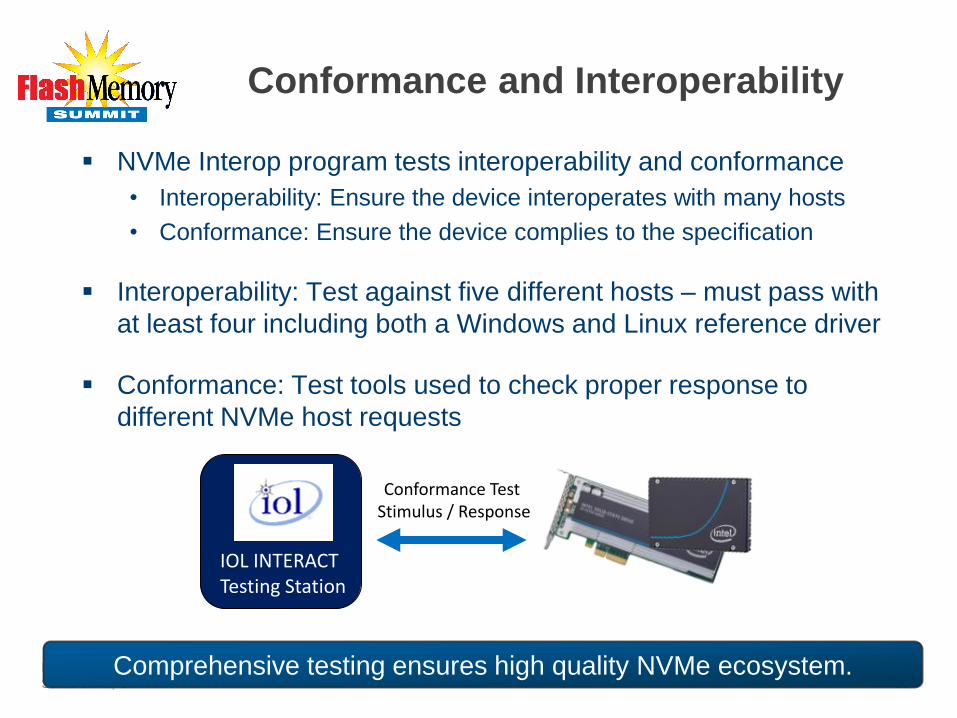
Conformance and Interoperability
NVMe Interop program tests interoperability and conformance
• Interoperability: Ensure the device interoperates with many hosts
• Conformance: Ensure the device complies to the specification
Interoperability: Test against five different hosts – must pass with
at least four including both a Windows and Linux reference driver
Conformance: Test tools used to check proper response to
different NVMe host requests
Flash Memory Summit 2014
Santa Clara, CA
28
IOL INTERACT Testing Station
Conformance Test Stimulus / Response
Comprehensive testing ensures high quality NVMe ecosystem.
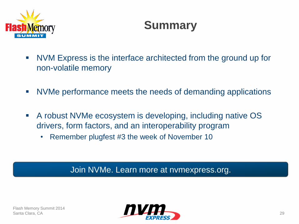
Summary
NVM Express is the interface architected from the ground up for
non-volatile memory
NVMe performance meets the needs of demanding applications
A robust NVMe ecosystem is developing, including native OS
drivers, form factors, and an interoperability program
• Remember plugfest #3 the week of November 10
Flash Memory Summit 2014
Santa Clara, CA
29
Join NVMe. Learn more at nvmexpress.org.
Audio-Visual Sponsor
What’s New in NVMe™ Rev 1.2?
Dave Landsman
Director, Standards and Industry Associations
SanDisk
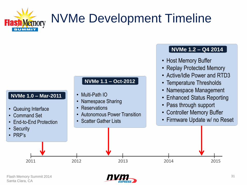
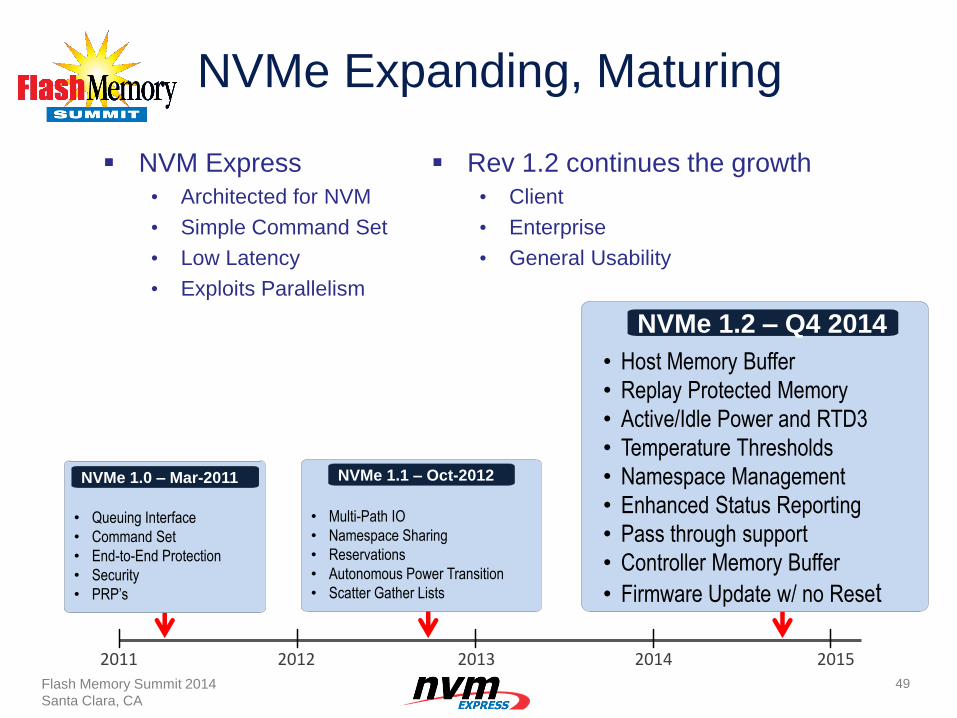
NVMe Development Timeline
31
2011 2012 2013 2014
• Host Memory Buffer
• Replay Protected Memory
• Active/Idle Power and RTD3
• Temperature Thresholds
• Namespace Management
• Enhanced Status Reporting
• Pass through support
• Controller Memory Buffer
• Firmware Update w/ no Reset
NVMe 1.2 – Q4 2014
• Multi-Path IO
• Namespace Sharing
• Reservations
• Autonomous Power Transition
• Scatter Gather Lists
NVMe 1.1 – Oct-2012
2015
• Queuing Interface
• Command Set
• End-to-End Protection
• Security
• PRP’s
NVMe 1.0 – Mar-2011
Flash Memory Summit 2014
Santa Clara, CA
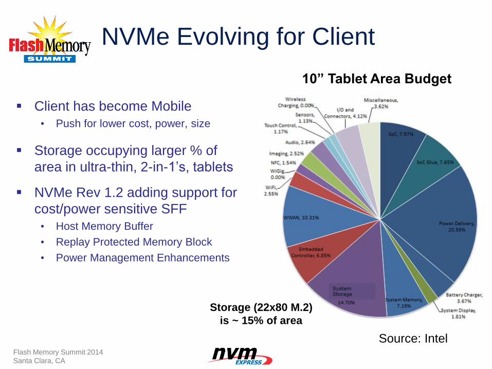
NVMe Evolving for Client
Client has become Mobile
• Push for lower cost, power, size
Storage occupying larger % of
area in ultra-thin, 2-in-1’s, tablets
NVMe Rev 1.2 adding support for
cost/power sensitive SFF
• Host Memory Buffer
• Replay Protected Memory Block
• Power Management Enhancements
Storage (22x80 M.2)
is ~ 15% of area
10” Tablet Area Budget
Source: Intel Flash Memory Summit 2014
Santa Clara, CA
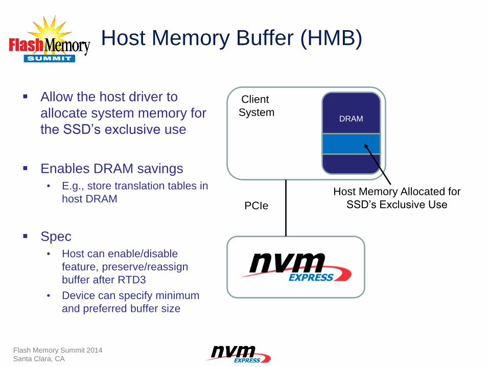
Host Memory Buffer (HMB)
Allow the host driver to
allocate system memory for
the SSD’s exclusive use
Enables DRAM savings
• E.g., store translation tables in
host DRAM
Spec
• Host can enable/disable
feature, preserve/reassign
buffer after RTD3
• Device can specify minimum
and preferred buffer size
DRAM
Client
System
Host Memory Allocated for
SSD’s Exclusive Use PCIe
Flash Memory Summit 2014
Santa Clara, CA
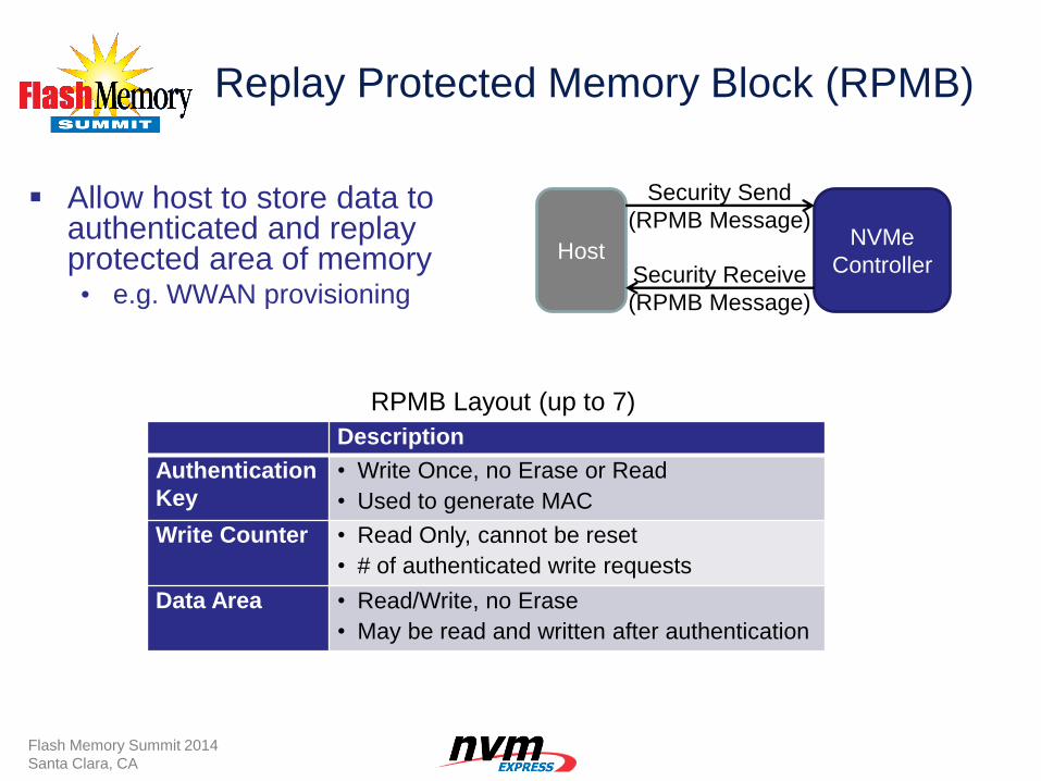
Replay Protected Memory Block (RPMB)
Allow host to store data to authenticated and replay protected area of memory • e.g. WWAN provisioning
Description
Authentication
Key
• Write Once, no Erase or Read
• Used to generate MAC
Write Counter • Read Only, cannot be reset
• # of authenticated write requests
Data Area • Read/Write, no Erase
• May be read and written after authentication
RPMB Layout (up to 7)
Response
(RPMB Message)
Host NVMe
Controller
Security Send
(RPMB Message)
Security Receive
(RPMB Message)
Flash Memory Summit 2014
Santa Clara, CA
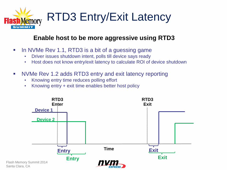
RTD3 Entry/Exit Latency
In NVMe Rev 1.1, RTD3 is a bit of a guessing game • Driver issues shutdown intent, polls till device says ready
• Host does not know entry/exit latency to calculate ROI of device shutdown
NVMe Rev 1.2 adds RTD3 entry and exit latency reporting • Knowing entry time reduces polling effort
• Knowing entry + exit time enables better host policy
Entry
Entry
Exit
Exit
Time
RTD3 Enter
RTD3 Exit
Device 1
Device 2
Enable host to be more aggressive using RTD3
Flash Memory Summit 2014
Santa Clara, CA
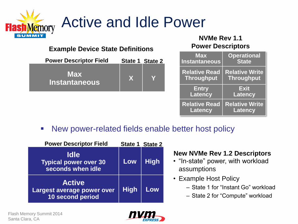
Active and Idle Power
New power-related fields enable better host policy
Max Instantaneous
X Y
• “In-state” power, with workload
assumptions
• Example Host Policy
– State 1 for “Instant Go” workload
– State 2 for “Compute” workload
NVMe Rev 1.1
Power Descriptors
New NVMe Rev 1.2 Descriptors
Example Device State Definitions
State 1 State 2 Power Descriptor Field
Flash Memory Summit 2014
Santa Clara, CA
Idle Typical power over 30
seconds when idle Low High
Active Largest average power over
10 second period High Low
Max Instantaneous
Operational State
Relative Read Throughput
Relative Write Throughput
Entry Latency
Exit Latency
Relative Read Latency
Relative Write Latency
State 1 State 2 Power Descriptor Field
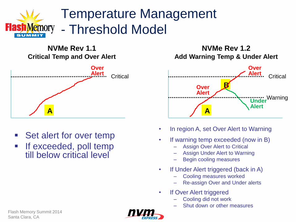
Temperature Management
- Threshold Model
Set alert for over temp
If exceeded, poll temp till below critical level
A
B
Critical
Warning
Over Alert
Under Alert
A
Critical
Over Alert
NVMe Rev 1.1 Critical Temp and Over Alert
NVMe Rev 1.2 Add Warning Temp & Under Alert
• In region A, set Over Alert to Warning
Over Alert
• If Under Alert triggered (back in A) – Cooling measures worked
– Re-assign Over and Under alerts
• If warning temp exceeded (now in B) – Assign Over Alert to Critical
– Assign Under Alert to Warning
– Begin cooling measures
• If Over Alert triggered – Cooling did not work
– Shut down or other measures Flash Memory Summit 2014
Santa Clara, CA
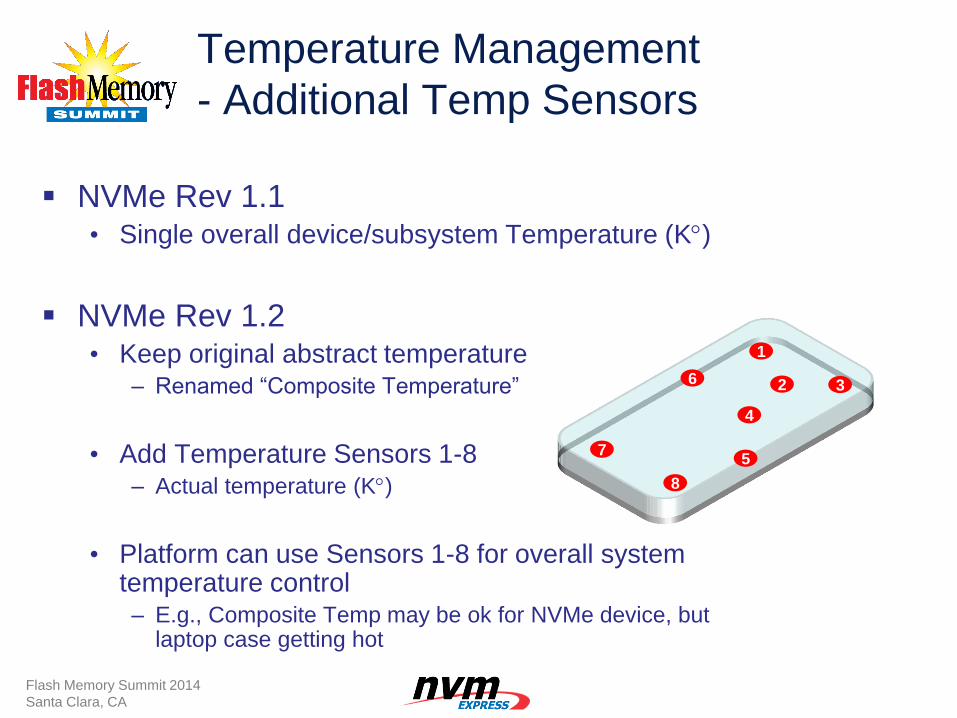
Temperature Management
- Additional Temp Sensors
NVMe Rev 1.1 • Single overall device/subsystem Temperature (K)
NVMe Rev 1.2 • Keep original abstract temperature
– Renamed “Composite Temperature”
• Add Temperature Sensors 1-8 – Actual temperature (K)
• Platform can use Sensors 1-8 for overall system temperature control – E.g., Composite Temp may be ok for NVMe device, but
laptop case getting hot
1
2
4
3
5
6
8
7
Flash Memory Summit 2014
Santa Clara, CA
Namespace Management
A namespace is a region of NVM, made visible to applications as
collection of logical blocks, which has defined Format, Features, PI, etc.
Each namespace is independent of other namespaces in the subsystem.
39
This example:
OS sees two drives
NS A = Disk 0
NS B = Disk 1
Logical partitions
on A and B
NVMe Controller
B
NVMe Subsystem
NSID 1 NSID 2
NS B NS A
NVM Pool
OEM’s and Customers wanted standard solution:
Configure any vendor’s drive with same tool
Flash Memory Summit 2014
Santa Clara, CA
• Today, creation/configuration of namespaces is vendor specific
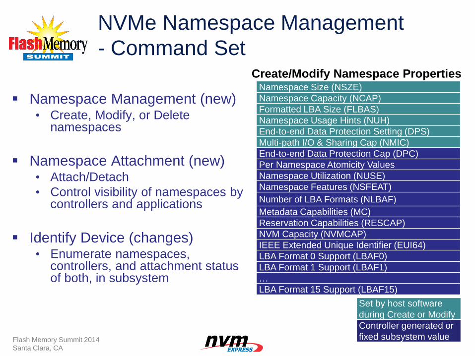
NVMe Namespace Management
- Command Set
Namespace Management (new) • Create, Modify, or Delete
namespaces
Namespace Attachment (new) • Attach/Detach
• Control visibility of namespaces by controllers and applications
Identify Device (changes) • Enumerate namespaces,
controllers, and attachment status of both, in subsystem
40
Namespace Size (NSZE)
Namespace Capacity (NCAP)
Formatted LBA Size (FLBAS)
Namespace Usage Hints (NUH)
End-to-end Data Protection Setting (DPS)
Multi-path I/O & Sharing Cap (NMIC)
End-to-end Data Protection Cap (DPC)
Per Namespace Atomicity Values
Namespace Utilization (NUSE)
Namespace Features (NSFEAT)
Number of LBA Formats (NLBAF)
Metadata Capabilities (MC)
Reservation Capabilities (RESCAP)
NVM Capacity (NVMCAP)
IEEE Extended Unique Identifier (EUI64)
LBA Format 0 Support (LBAF0)
LBA Format 1 Support (LBAF1)
…
LBA Format 15 Support (LBAF15)
Create/Modify Namespace Properties
Set by host software
during Create or Modify
Controller generated or
fixed subsystem value Flash Memory Summit 2014
Santa Clara, CA
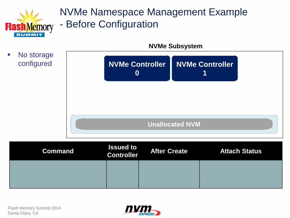
NVMe Namespace Management Example
- Before Configuration
No storage
configured
Command Issued to
Controller After Create Attach Status
NVMe Controller
0
B
NVMe Controller
1
Unallocated NVM
NVMe Subsystem
Flash Memory Summit 2014
Santa Clara, CA
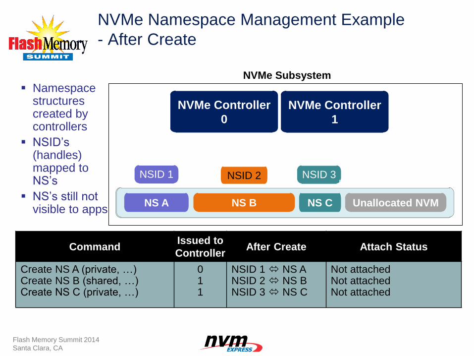
NVMe Namespace Management Example
- After Create
Command Issued to
Controller After Create Attach Status
Create NS A (private, …) Create NS B (shared, …) Create NS C (private, …)
0 1 1
NSID 1 NS A NSID 2 NS B NSID 3 NS C
Not attached Not attached Not attached
Namespace structures created by controllers
NSID’s (handles) mapped to NS’s
NS’s still not visible to apps
NVMe Controller
0
NSID 3 B
NSID 1 NSID 2
NVMe Controller
1
Unallocated NVM Unallocated NVM NS C NS B NS A
NVMe Subsystem
Flash Memory Summit 2014
Santa Clara, CA
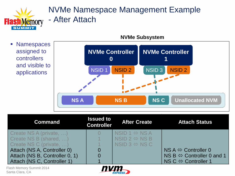
NVMe Namespace Management Example
- After Attach
Command Issued to
Controller After Create Attach Status
Create NS A (private, …) Create NS B (shared, …) Create NS C (private, …) Attach (NS A, Controller 0) Attach (NS B, Controller 0, 1) Attach (NS C, Controller 1)
0 1 1 0 0 1
NSID 1 NS A NSID 2 NS B NSID 3 NS C
NS A Controller 0 NS B Controller 0 and 1 NS C Controller 1
Namespaces
assigned to
controllers
and visible to
applications
NVMe Controller
0
NSID 3
B
NSID 1 NSID 2
NVMe Controller
1
Unallocated NVM Unallocated NVM NS C NS B NS A
NSID 2
NVMe Subsystem
Flash Memory Summit 2014
Santa Clara, CA
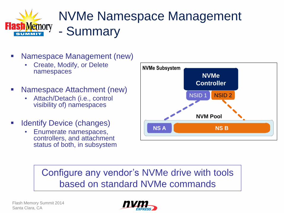
NVMe Namespace Management
- Summary
Namespace Management (new) • Create, Modify, or Delete
namespaces
Namespace Attachment (new) • Attach/Detach (i.e., control
visibility of) namespaces
Identify Device (changes) • Enumerate namespaces,
controllers, and attachment status of both, in subsystem
Flash Memory Summit 2014
Santa Clara, CA
NVMe
Controller
B
NVMe Subsystem
NSID 1 NSID 2
NS B NS A
NVM Pool
Configure any vendor’s NVMe drive with tools
based on standard NVMe commands
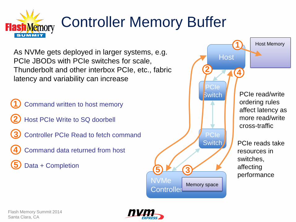
Controller Memory Buffer
Command written to host memory
Host PCIe Write to SQ doorbell
Controller PCIe Read to fetch command
Command data returned from host
Data + Completion
NVMe
Controller Memory space
Host
PCIe
Switch
PCIe
Switch
Host Memory
1
2
3
4
5
2
3
1
4
5
As NVMe gets deployed in larger systems, e.g.
PCIe JBODs with PCIe switches for scale,
Thunderbolt and other interbox PCIe, etc., fabric
latency and variability can increase
Flash Memory Summit 2014
Santa Clara, CA
PCIe reads take
resources in
switches,
affecting
performance
PCIe read/write
ordering rules
affect latency as
more read/write
cross-traffic
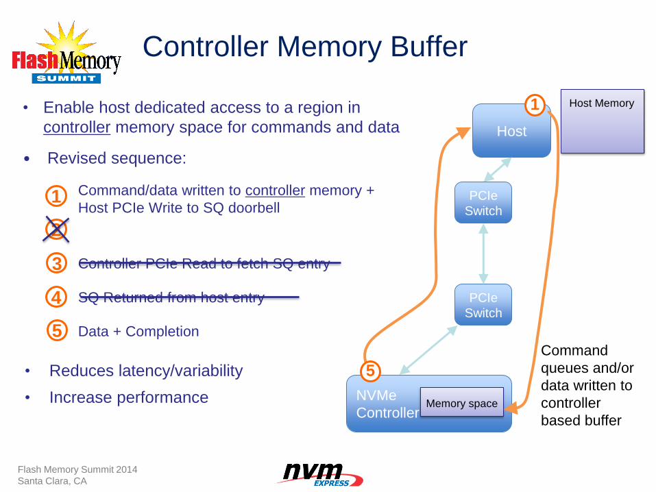
Controller Memory Buffer
• Reduces latency/variability
• Increase performance
NVMe
Controller Memory space
Host
PCIe
Switch
PCIe
Switch
1 Host Memory
5
• Enable host dedicated access to a region in
controller memory space for commands and data
• Revised sequence:
1
2
3
4
5
Command/data written to controller memory +
Host PCIe Write to SQ doorbell
Controller PCIe Read to fetch SQ entry
SQ Returned from host entry
Data + Completion
Flash Memory Summit 2014
Santa Clara, CA
Command
queues and/or
data written to
controller
based buffer
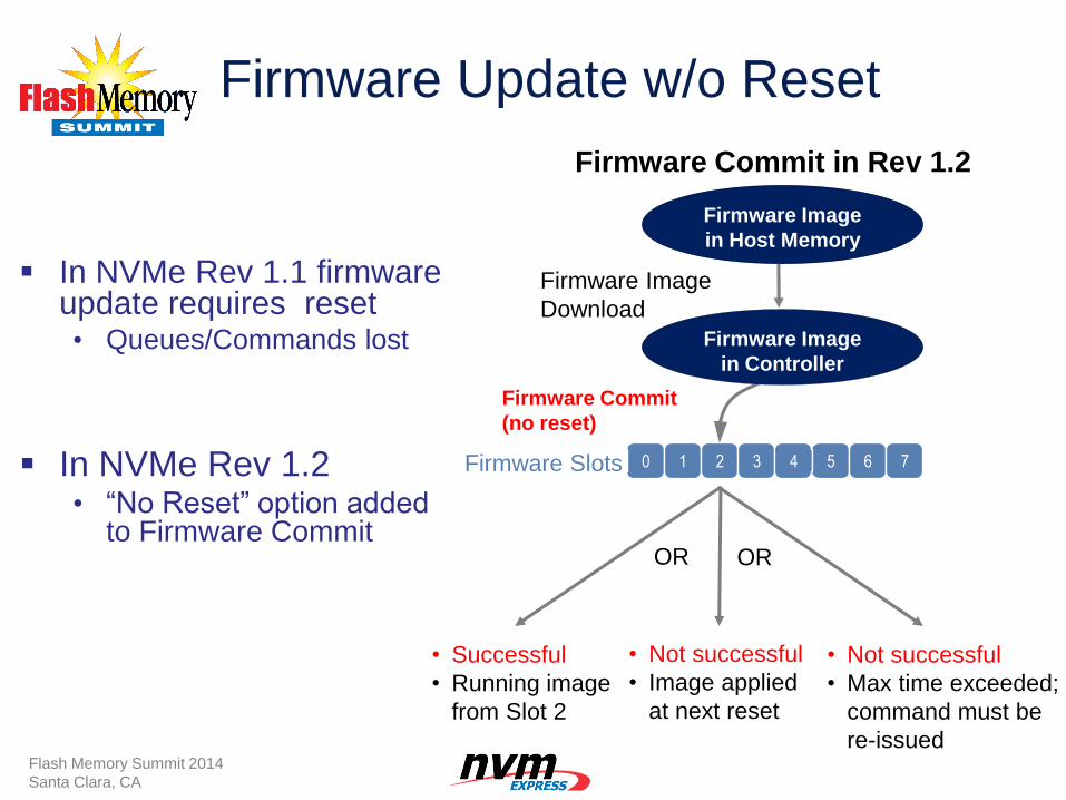
Firmware Update w/o Reset
In NVMe Rev 1.1 firmware update requires reset • Queues/Commands lost
0
Firmware Image
in Host Memory
1 2 3 4 5 6 7
Firmware Image
Download
Firmware Slots
Firmware Commit
(no reset)
• Successful
• Running image
from Slot 2
• Not successful
• Image applied
at next reset
• Not successful
• Max time exceeded;
command must be
re-issued
OR OR
Firmware Commit in Rev 1.2
Firmware Image
in Controller
Flash Memory Summit 2014
Santa Clara, CA
In NVMe Rev 1.2 • “No Reset” option added
to Firmware Commit
Other NVMe Rev 1.2 Features
Atomicity enhancements
Command Effects Log (pass-through)
Enhanced Status Reporting
NVMe Expanding, Maturing
49 Flash Memory Summit 2014
Santa Clara, CA
2011 2012 2013 2014
• Host Memory Buffer
• Replay Protected Memory
• Active/Idle Power and RTD3
• Temperature Thresholds
• Namespace Management
• Enhanced Status Reporting
• Pass through support
• Controller Memory Buffer
• Firmware Update w/ no Reset
NVMe 1.2 – Q4 2014
• Multi-Path IO
• Namespace Sharing
• Reservations
• Autonomous Power Transition
• Scatter Gather Lists
NVMe 1.1 – Oct-2012
2015
• Queuing Interface
• Command Set
• End-to-End Protection
• Security
• PRP’s
NVMe 1.0 – Mar-2011
NVM Express
• Architected for NVM
• Simple Command Set
• Low Latency
• Exploits Parallelism
Rev 1.2 continues the growth
• Client
• Enterprise
• General Usability
Thank You!
Audio-Visual Sponsor
NVM Express Management Interface
Peter Onufryk
Sr. Director Product Development
PMC Sierra
Austin Bolen
Storage Development Principal
Engineer
Dell
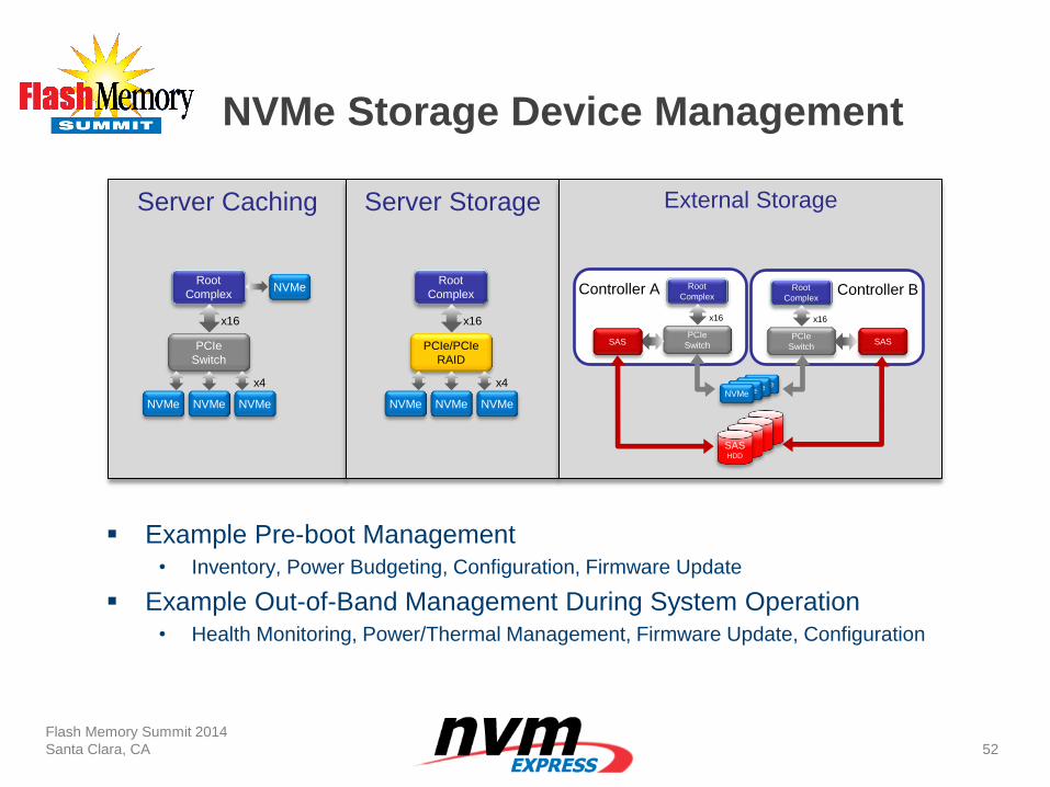
NVMe Storage Device Management
Flash Memory Summit 2014
Santa Clara, CA
52
Server Caching Server Storage External Storage
Root
Complex
PCIe/PCIe
RAID
NVMe NVMe NVMe
x16
x4
Root
Complex NVMe
PCIe
Switch
NVMe NVMe NVMe
x16
x4
Controller A Controller B Root
Complex
PCIe
Switch
x16
Root
Complex
PCIe
Switch
x16
SAS SAS
NVMe NVMe NVMe NVMe
SAS HDD
Example Pre-boot Management • Inventory, Power Budgeting, Configuration, Firmware Update
Example Out-of-Band Management During System Operation • Health Monitoring, Power/Thermal Management, Firmware Update, Configuration
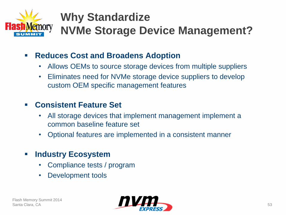
Why Standardize
NVMe Storage Device Management?
Reduces Cost and Broadens Adoption
• Allows OEMs to source storage devices from multiple suppliers
• Eliminates need for NVMe storage device suppliers to develop
custom OEM specific management features
Consistent Feature Set
• All storage devices that implement management implement a
common baseline feature set
• Optional features are implemented in a consistent manner
Industry Ecosystem
• Compliance tests / program
• Development tools
Flash Memory Summit 2014
Santa Clara, CA
53
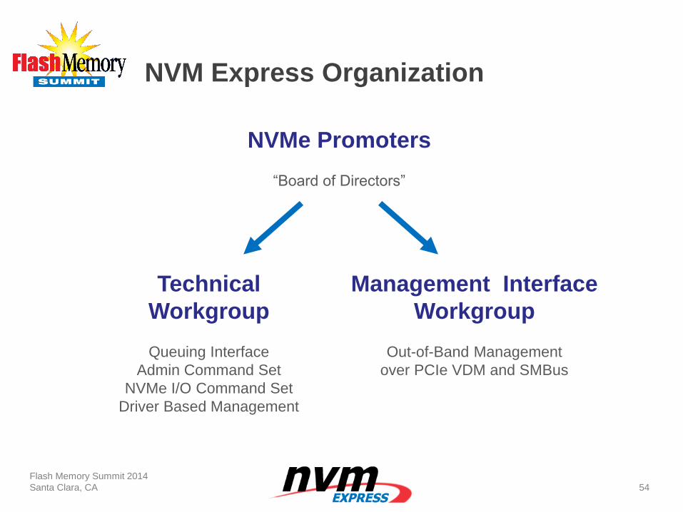
NVM Express Organization
Flash Memory Summit 2014
Santa Clara, CA
54
NVMe Promoters
“Board of Directors”
Technical
Workgroup
Queuing Interface
Admin Command Set
NVMe I/O Command Set
Driver Based Management
Management Interface
Workgroup
Out-of-Band Management
over PCIe VDM and SMBus
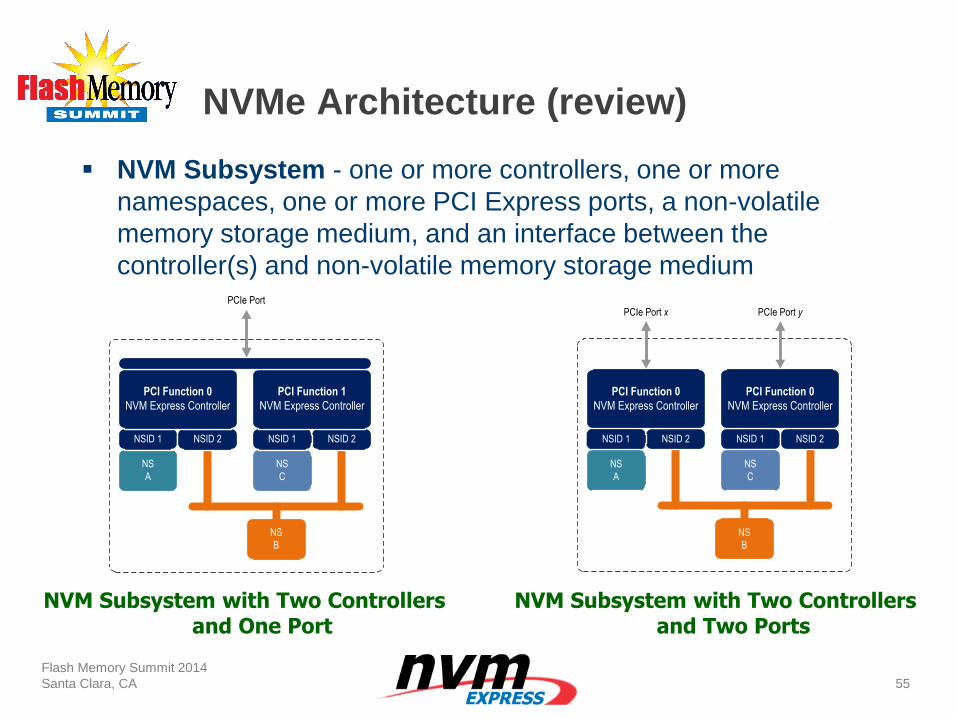
NVMe Architecture (review)
Flash Memory Summit 2014
Santa Clara, CA
55
NSID 1 NSID 2
PCI Function 0
NVM Express Controller
PCIe Port
NS
A
NS
B
NSID 1 NSID 2
PCI Function 1
NVM Express Controller
NS
C
NSID 1 NSID 2
PCI Function 0
NVM Express Controller
NS
A
NS
B
NSID 1 NSID 2
PCI Function 0
NVM Express Controller
NS
C
PCIe Port x PCIe Port y
NVM Subsystem - one or more controllers, one or more
namespaces, one or more PCI Express ports, a non-volatile
memory storage medium, and an interface between the
controller(s) and non-volatile memory storage medium
NVM Subsystem with Two Controllers and One Port
NVM Subsystem with Two Controllers and Two Ports
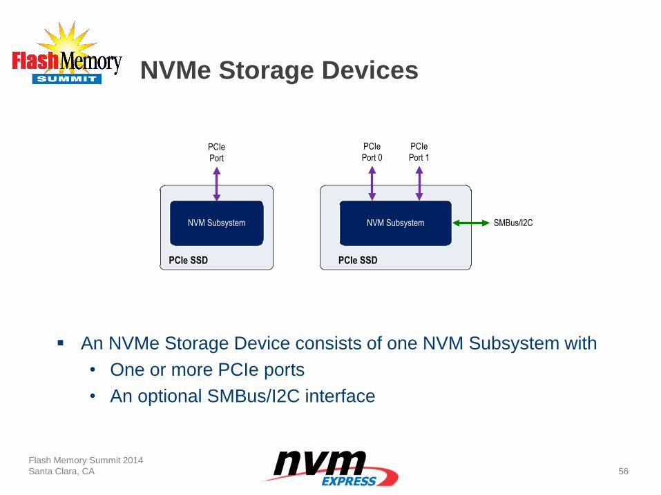
NVMe Storage Devices
Flash Memory Summit 2014
Santa Clara, CA
56
An NVMe Storage Device consists of one NVM Subsystem with
• One or more PCIe ports
• An optional SMBus/I2C interface
NVM Subsystem
PCIe SSD
NVM Subsystem
PCIe
Port 0
PCIe SSD
PCIe
Port 1PCIe
Port
SMBus/I2C
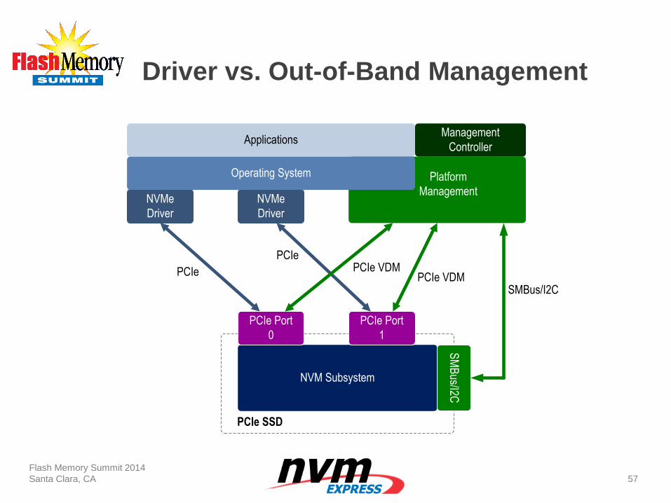
Driver vs. Out-of-Band Management
Flash Memory Summit 2014
Santa Clara, CA
57
NVM Subsystem
PCIe
PCIe SSD
PCIe Port
0
PCIe Port
1
SM
Bus/I2C
NVMe
Driver
NVMe
Driver
ApplicationsManagement
Controller
Operating System Platform
Management
PCIePCIe VDM
PCIe VDMSMBus/I2C
Management Interface Workgroup
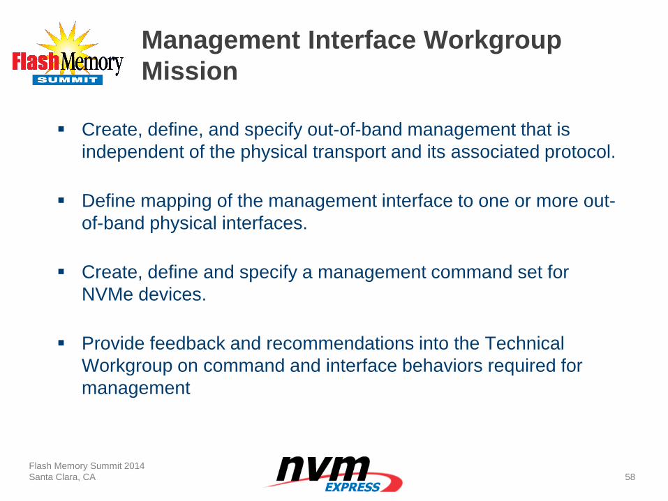
Mission
Create, define, and specify out-of-band management that is
independent of the physical transport and its associated protocol.
Define mapping of the management interface to one or more out-
of-band physical interfaces.
Create, define and specify a management command set for
NVMe devices.
Provide feedback and recommendations into the Technical
Workgroup on command and interface behaviors required for
management
Flash Memory Summit 2014
Santa Clara, CA
58
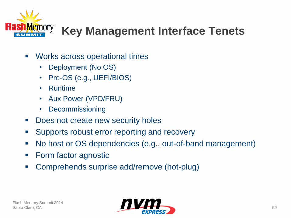
Key Management Interface Tenets
Works across operational times
• Deployment (No OS)
• Pre-OS (e.g., UEFI/BIOS)
• Runtime
• Aux Power (VPD/FRU)
• Decommissioning
Does not create new security holes
Supports robust error reporting and recovery
No host or OS dependencies (e.g., out-of-band management)
Form factor agnostic
Comprehends surprise add/remove (hot-plug)
Flash Memory Summit 2014
Santa Clara, CA
59
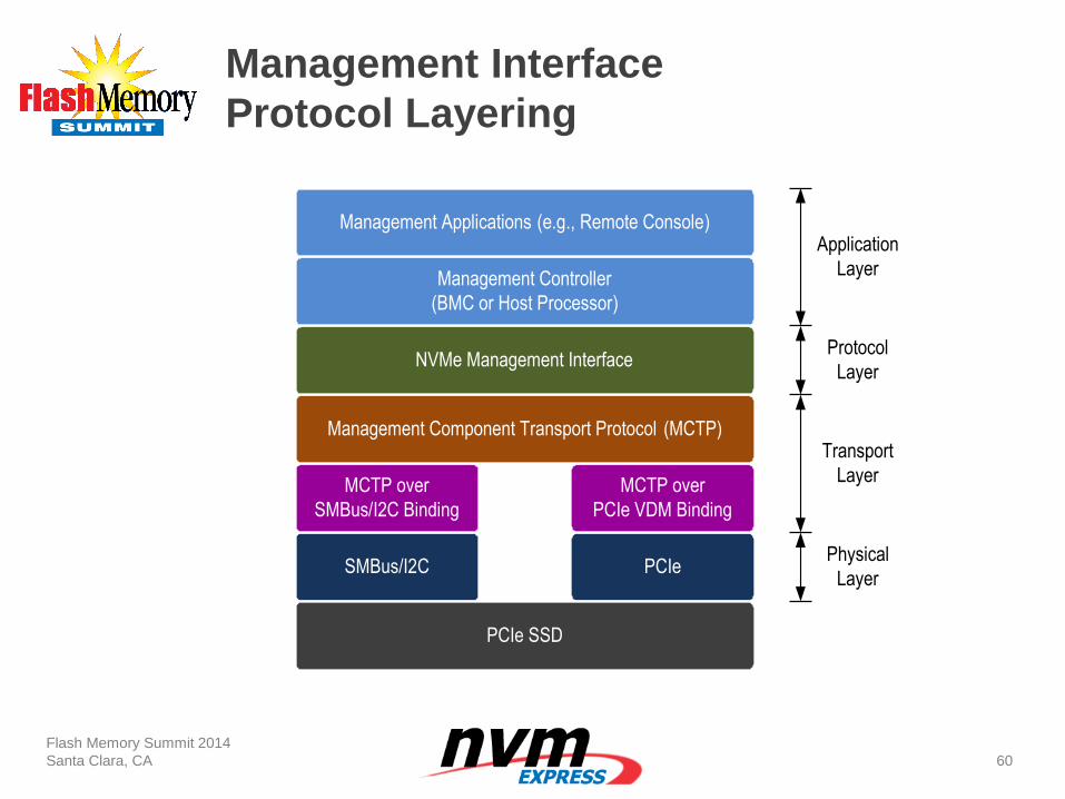
Management Interface
Protocol Layering
Flash Memory Summit 2014
Santa Clara, CA
60
Management
Applications (e.g.,
Remote Console)
SMBus/I2C PCIe
MCTP over
SMBus/I2C Binding
MCTP over
PCIe VDM Binding
Management Component Transport Protocol (MCTP)
NVMe Management Interface
Management Controller
(BMC or Host Processor)
Management Applications (e.g., Remote Console)
Physical
Layer
Transport
Layer
Protocol
Layer
Application
Layer
PCIe SSD
NVMe Management Interface
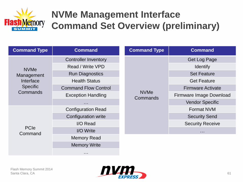
Command Set Overview (preliminary)
Flash Memory Summit 2014
Santa Clara, CA
61
Command Type Command
NVMe
Management
Interface
Specific
Commands
Controller Inventory
Read / Write VPD
Run Diagnostics
Health Status
Command Flow Control
Exception Handling
…
PCIe
Command
Configuration Read
Configuration write
I/O Read
I/O Write
Memory Read
Memory Write
…
Command Type Command
NVMe
Commands
Get Log Page
Identify
Set Feature
Get Feature
Firmware Activate
Firmware Image Download
Vendor Specific
Format NVM
Security Send
Security Receive
…
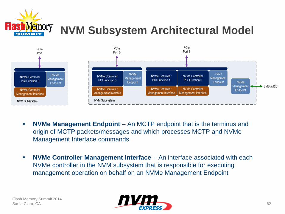
NVM Subsystem Architectural Model
Flash Memory Summit 2014
Santa Clara, CA
62
NVMe Management Endpoint – An MCTP endpoint that is the terminus and
origin of MCTP packets/messages and which processes MCTP and NVMe
Management Interface commands
NVMe Controller Management Interface – An interface associated with each
NVMe controller in the NVM subsystem that is responsible for executing
management operation on behalf on an NVMe Management Endpoint
NVMe Controller
PCI Function 0
NVMe
Management
Endpoint
NVM Subsystem
NVMe Controller
Management Interface
PCIe
Port
NVMe Controller
PCI Function 0
NVMe
Management
Endpoint
NVM Subsystem
NVMe Controller
Management Interface
PCIe
Port 0
NVMe Controller
PCI Function 0
NVMe
Management
Endpoint
NVMe Controller
Management Interface
PCIe
Port 1
NVMe
Management
EndpointSMBus/I2C
NVMe Controller
PCI Function 1
NVMe Controller
Management Interface
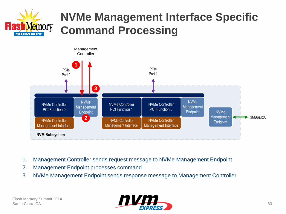
NVMe Management Interface Specific
Command Processing
Flash Memory Summit 2014
Santa Clara, CA
63
1. Management Controller sends request message to NVMe Management Endpoint
2. Management Endpoint processes command
3. NVMe Management Endpoint sends response message to Management Controller
NVMe Controller
PCI Function 0
NVMe
Management
Endpoint
NVM Subsystem
NVMe Controller
Management Interface
PCIe
Port 0
NVMe Controller
PCI Function 0
NVMe
Management
Endpoint
NVMe Controller
Management Interface
PCIe
Port 1
NVMe
Management
EndpointSMBus/I2C
NVMe Controller
PCI Function 1
NVMe Controller
Management Interface
1
Management
Controller
2
3
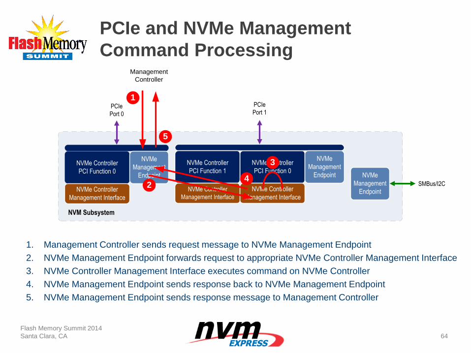
PCIe and NVMe Management
Command Processing
Flash Memory Summit 2014
Santa Clara, CA
64
1. Management Controller sends request message to NVMe Management Endpoint
2. NVMe Management Endpoint forwards request to appropriate NVMe Controller Management Interface
3. NVMe Controller Management Interface executes command on NVMe Controller
4. NVMe Management Endpoint sends response back to NVMe Management Endpoint
5. NVMe Management Endpoint sends response message to Management Controller
NVMe Controller
PCI Function 0
NVMe
Management
Endpoint
NVM Subsystem
NVMe Controller
Management Interface
PCIe
Port 0
NVMe Controller
PCI Function 0
NVMe
Management
Endpoint
NVMe Controller
Management Interface
PCIe
Port 1
NVMe
Management
EndpointSMBus/I2C
NVMe Controller
PCI Function 1
NVMe Controller
Management Interface
1
Management
Controller
2
3
4
5
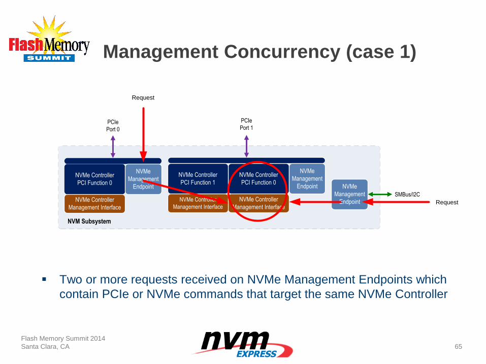
Management Concurrency (case 1)
Two or more requests received on NVMe Management Endpoints which
contain PCIe or NVMe commands that target the same NVMe Controller
Flash Memory Summit 2014
Santa Clara, CA
65
NVMe Controller
PCI Function 0
NVMe
Management
Endpoint
NVM Subsystem
NVMe Controller
Management Interface
PCIe
Port 0
NVMe Controller
PCI Function 0
NVMe
Management
Endpoint
NVMe Controller
Management Interface
PCIe
Port 1
NVMe
Management
EndpointSMBus/I2C
NVMe Controller
PCI Function 1
NVMe Controller
Management Interface
Request
Request
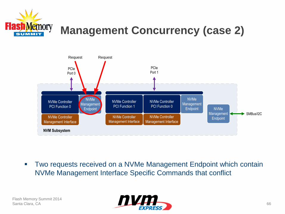
Management Concurrency (case 2)
Two requests received on a NVMe Management Endpoint which contain
NVMe Management Interface Specific Commands that conflict
Flash Memory Summit 2014
Santa Clara, CA
66
NVMe Controller
PCI Function 0
NVMe
Management
Endpoint
NVM Subsystem
NVMe Controller
Management Interface
PCIe
Port 0
NVMe Controller
PCI Function 0
NVMe
Management
Endpoint
NVMe Controller
Management Interface
PCIe
Port 1
NVMe
Management
EndpointSMBus/I2C
NVMe Controller
PCI Function 1
NVMe Controller
Management Interface
RequestRequest
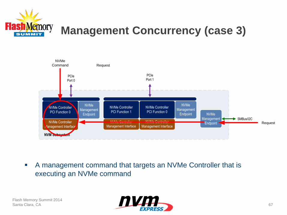
Management Concurrency (case 3)
A management command that targets an NVMe Controller that is
executing an NVMe command
Flash Memory Summit 2014
Santa Clara, CA
67
NVMe Controller
PCI Function 0
NVMe
Management
Endpoint
NVM Subsystem
NVMe Controller
Management Interface
PCIe
Port 0
NVMe Controller
PCI Function 0
NVMe
Management
Endpoint
NVMe Controller
Management Interface
PCIe
Port 1
NVMe
Management
EndpointSMBus/I2C
NVMe Controller
PCI Function 1
NVMe Controller
Management Interface
Request
NVMe
Command
Request
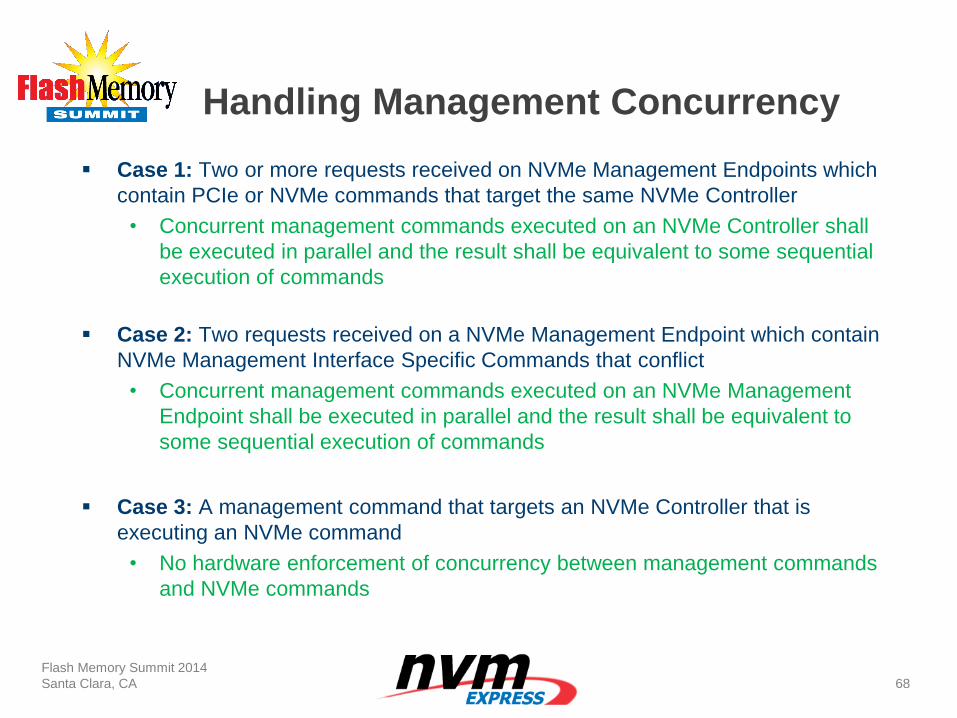
Handling Management Concurrency
Case 1: Two or more requests received on NVMe Management Endpoints which
contain PCIe or NVMe commands that target the same NVMe Controller
• Concurrent management commands executed on an NVMe Controller shall
be executed in parallel and the result shall be equivalent to some sequential
execution of commands
Case 2: Two requests received on a NVMe Management Endpoint which contain
NVMe Management Interface Specific Commands that conflict
• Concurrent management commands executed on an NVMe Management
Endpoint shall be executed in parallel and the result shall be equivalent to
some sequential execution of commands
Case 3: A management command that targets an NVMe Controller that is
executing an NVMe command
• No hardware enforcement of concurrency between management commands
and NVMe commands
Flash Memory Summit 2014
Santa Clara, CA
68
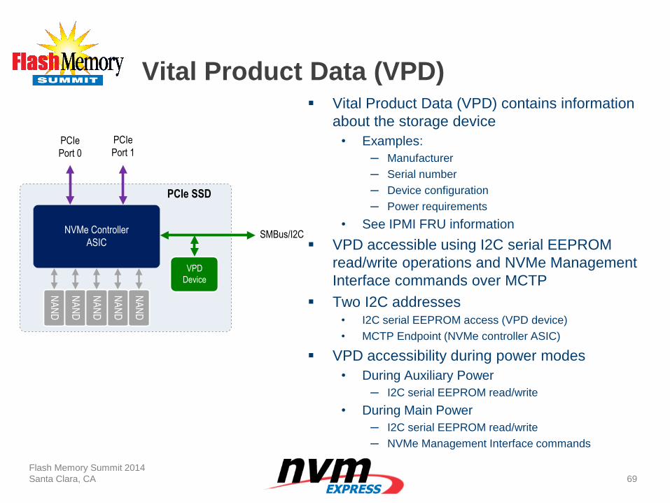
Vital Product Data (VPD)
Flash Memory Summit 2014
Santa Clara, CA
69
Vital Product Data (VPD) contains information
about the storage device
• Examples:
─ Manufacturer
─ Serial number
─ Device configuration
─ Power requirements
• See IPMI FRU information
VPD accessible using I2C serial EEPROM
read/write operations and NVMe Management
Interface commands over MCTP
Two I2C addresses • I2C serial EEPROM access (VPD device)
• MCTP Endpoint (NVMe controller ASIC)
VPD accessibility during power modes
• During Auxiliary Power
─ I2C serial EEPROM read/write
• During Main Power
─ I2C serial EEPROM read/write
─ NVMe Management Interface commands
NVMe Controller
ASIC
PCIe
Port 0
PCIe
Port 1
NA
ND
NA
ND
NA
ND
NA
ND
NA
ND
VPD
Device
SMBus/I2C
PCIe SSD
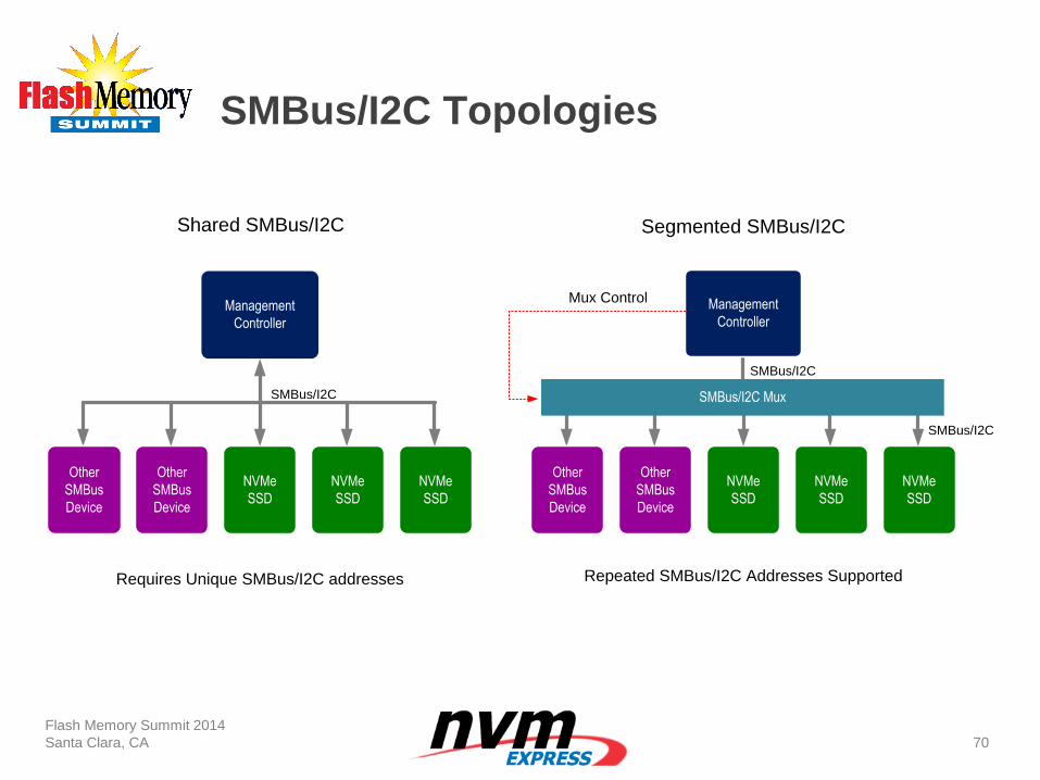
SMBus/I2C Topologies
Flash Memory Summit 2014
Santa Clara, CA
70
Management
Controller
NVMe
SSD
NVMe
SSD
NVMe
SSD
Other
SMBus
Device
Other
SMBus
Device
Management
Controller
NVMe
SSD
NVMe
SSD
NVMe
SSD
Other
SMBus
Device
Other
SMBus
Device
SMBus/I2C Mux
Mux Control
SMBus/I2C
SMBus/I2C
Shared SMBus/I2C Segmented SMBus/I2C
Requires Unique SMBus/I2C addresses Repeated SMBus/I2C Addresses Supported
SMBus/I2C
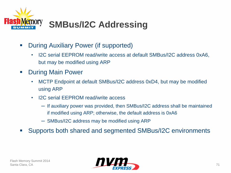
SMBus/I2C Addressing
During Auxiliary Power (if supported)
• I2C serial EEPROM read/write access at default SMBus/I2C address 0xA6,
but may be modified using ARP
During Main Power
• MCTP Endpoint at default SMBus/I2C address 0xD4, but may be modified
using ARP
• I2C serial EEPROM read/write access
─ If auxiliary power was provided, then SMBus/I2C address shall be maintained
if modified using ARP; otherwise, the default address is 0xA6
─ SMBus/I2C address may be modified using ARP
Supports both shared and segmented SMBus/I2C environments
Flash Memory Summit 2014
Santa Clara, CA
71
Summary
We are standardizing out-of-band management interface for NVMe
storage devices
• PCIe VDM and SMBus/I2C
The NVMe management interface is leveraging other management
specifications/standards
• Complementary and not a replacement
The specification is planned to be completed at the end of this year
Flash Memory Summit 2014
Santa Clara, CA
72
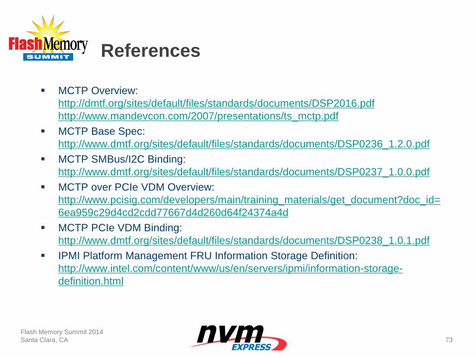
References
MCTP Overview:
http://dmtf.org/sites/default/files/standards/documents/DSP2016.pdf
http://www.mandevcon.com/2007/presentations/ts_mctp.pdf
MCTP Base Spec:
http://www.dmtf.org/sites/default/files/standards/documents/DSP0236_1.2.0.pdf
MCTP SMBus/I2C Binding:
http://www.dmtf.org/sites/default/files/standards/documents/DSP0237_1.0.0.pdf
MCTP over PCIe VDM Overview:
http://www.pcisig.com/developers/main/training_materials/get_document?doc_id=
6ea959c29d4cd2cdd77667d4d260d64f24374a4d
MCTP PCIe VDM Binding:
http://www.dmtf.org/sites/default/files/standards/documents/DSP0238_1.0.1.pdf
IPMI Platform Management FRU Information Storage Definition:
http://www.intel.com/content/www/us/en/servers/ipmi/information-storage-
definition.html
Flash Memory Summit 2014
Santa Clara, CA
73
Contents
Flash Memory Summit 2014
Santa Clara, CA
75
Where we are now
Latest Additions
Future Possibilities
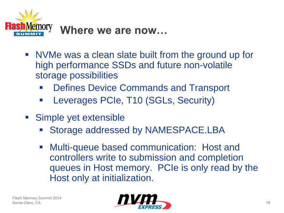
Where we are now…
Flash Memory Summit 2014
Santa Clara, CA
76
NVMe was a clean slate built from the ground up for high performance SSDs and future non-volatile storage possibilities
Defines Device Commands and Transport
Leverages PCIe, T10 (SGLs, Security)
Simple yet extensible
Storage addressed by NAMESPACE.LBA
Multi-queue based communication: Host and controllers write to submission and completion queues in Host memory. PCIe is only read by the Host only at initialization.
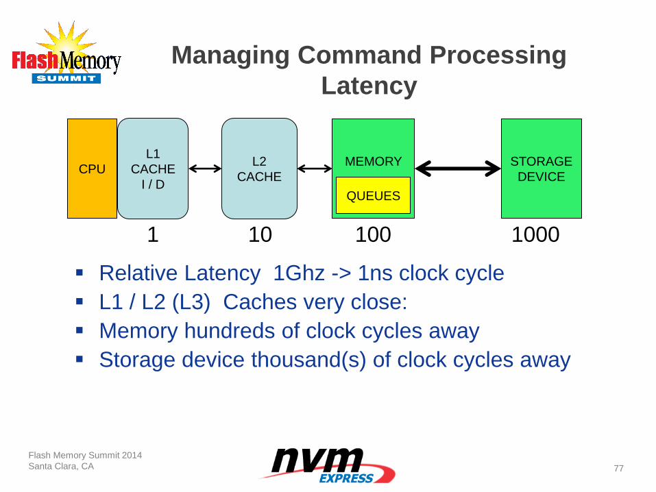
Flash Memory Summit 2014
Santa Clara, CA
77
CPU
L1
CACHE
I / D
Managing Command Processing
Latency
MEMORY
STORAGE
DEVICE
Relative Latency 1Ghz -> 1ns clock cycle
L1 / L2 (L3) Caches very close:
Memory hundreds of clock cycles away
Storage device thousand(s) of clock cycles away
1 10 100 1000
QUEUES
L2
CACHE
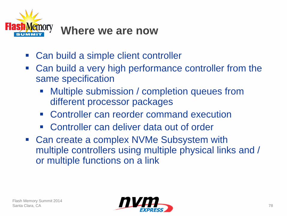
Where we are now
Flash Memory Summit 2014
Santa Clara, CA
78
Can build a simple client controller
Can build a very high performance controller from the same specification
Multiple submission / completion queues from different processor packages
Controller can reorder command execution
Controller can deliver data out of order
Can create a complex NVMe Subsystem with multiple controllers using multiple physical links and / or multiple functions on a link
VM
#4
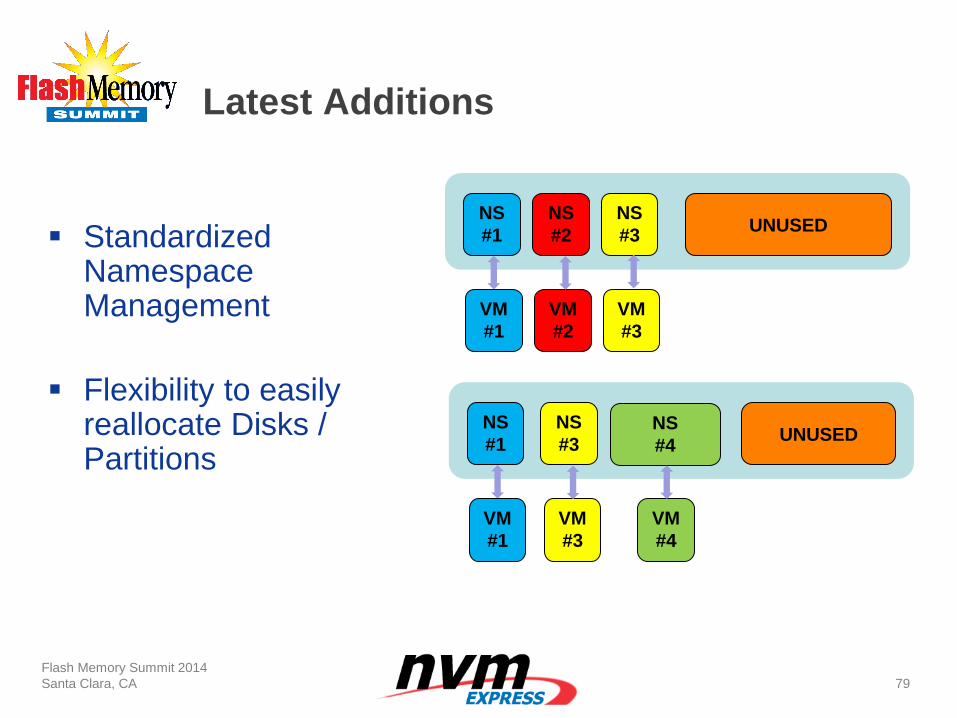
Latest Additions
Flash Memory Summit 2014
Santa Clara, CA
79
Standardized Namespace Management
Flexibility to easily reallocate Disks / Partitions
NS
#1
NS
#2
NS
#3 UNUSED
VM
#1
VM
#2
VM
#3
NS
#1 NS
#4
NS
#3 UNUSED
VM
#1
VM
#3
Latest Additions
Flash Memory Summit 2014
Santa Clara, CA
80
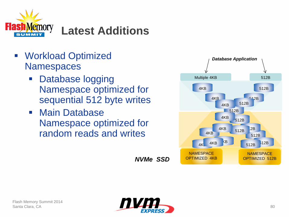
Workload Optimized Namespaces
Database logging Namespace optimized for sequential 512 byte writes
Main Database Namespace optimized for random reads and writes 512B
512B
512B
512B
512B
512B
512B
512B
512B
NAMESPACE
OPTIMIZED 4KB
NVMe SSD
Multiple 4KB 512B
Database Application
4KB 4KB
4KB
4KB
4KB
4KB
4KB 4KB
NAMESPACE
OPTIMIZED 512B
512B 4KB
Latest Additions
Flash Memory Summit 2014
Santa Clara, CA
81
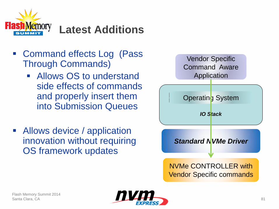
Command effects Log (Pass Through Commands)
Allows OS to understand side effects of commands and properly insert them into Submission Queues
Allows device / application innovation without requiring OS framework updates
Vendor Specific
Command Aware
Application
Operating System
IO Stack
Standard NVMe Driver
NVMe CONTROLLER with
Vendor Specific commands
Latest Additions
Flash Memory Summit 2014
Santa Clara, CA
82
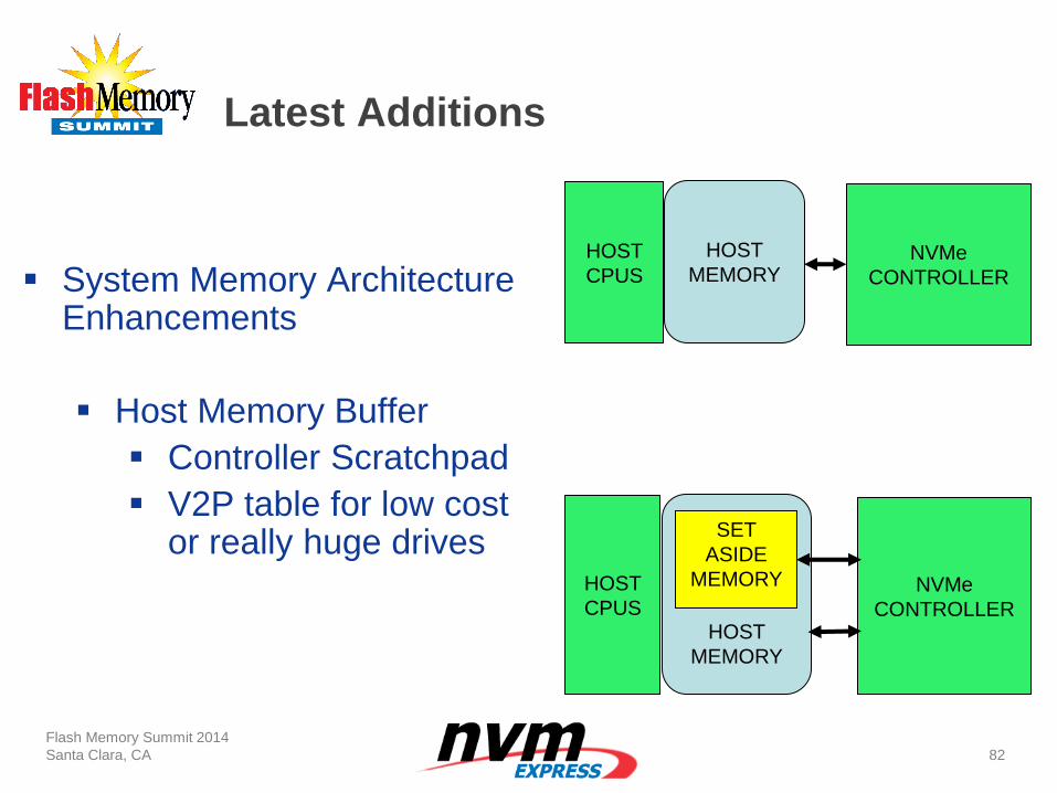
System Memory Architecture Enhancements
Host Memory Buffer
Controller Scratchpad
V2P table for low cost or really huge drives
HOST
CPUS
HOST
MEMORY
HOST
CPUS
HOST
MEMORY
NVMe
CONTROLLER
SET
ASIDE
MEMORY
NVMe
CONTROLLER
Latest Additions
Flash Memory Summit 2014
Santa Clara, CA
83
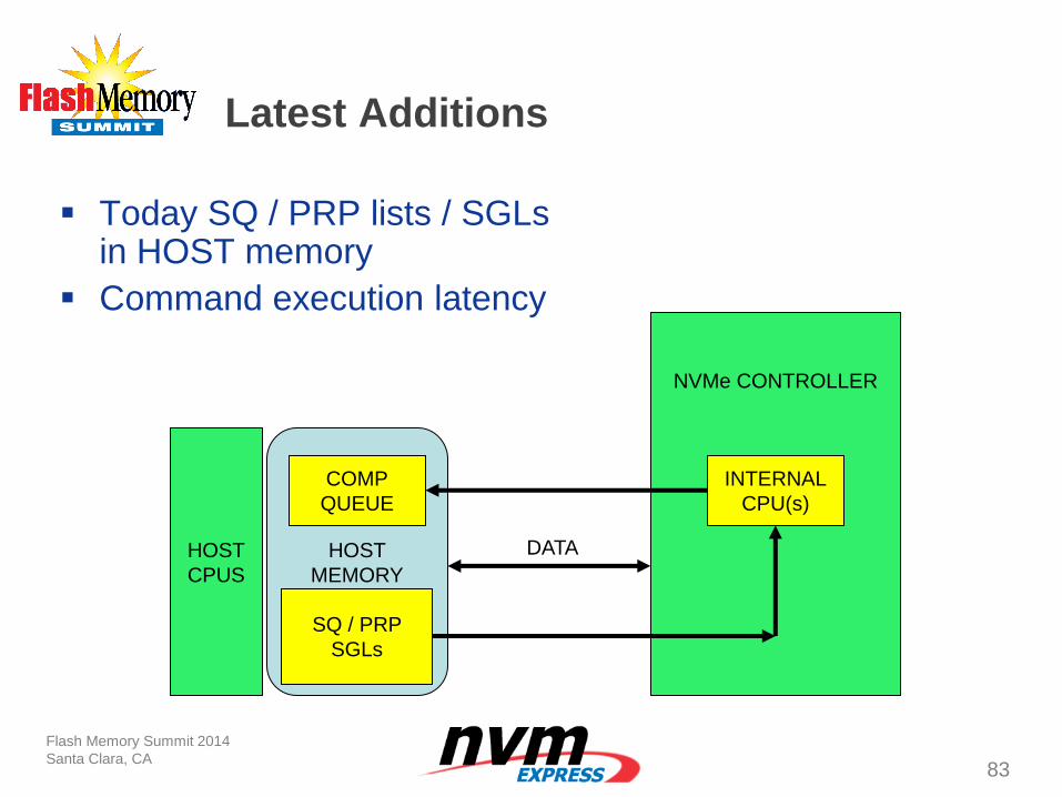
Today SQ / PRP lists / SGLs in HOST memory
Command execution latency
HOST
CPUS
HOST
MEMORY
NVMe CONTROLLER
COMP
QUEUE
SQ / PRP
SGLs
INTERNAL
CPU(s)
DATA
Latest Additions
Flash Memory Summit 2014
Santa Clara, CA
84
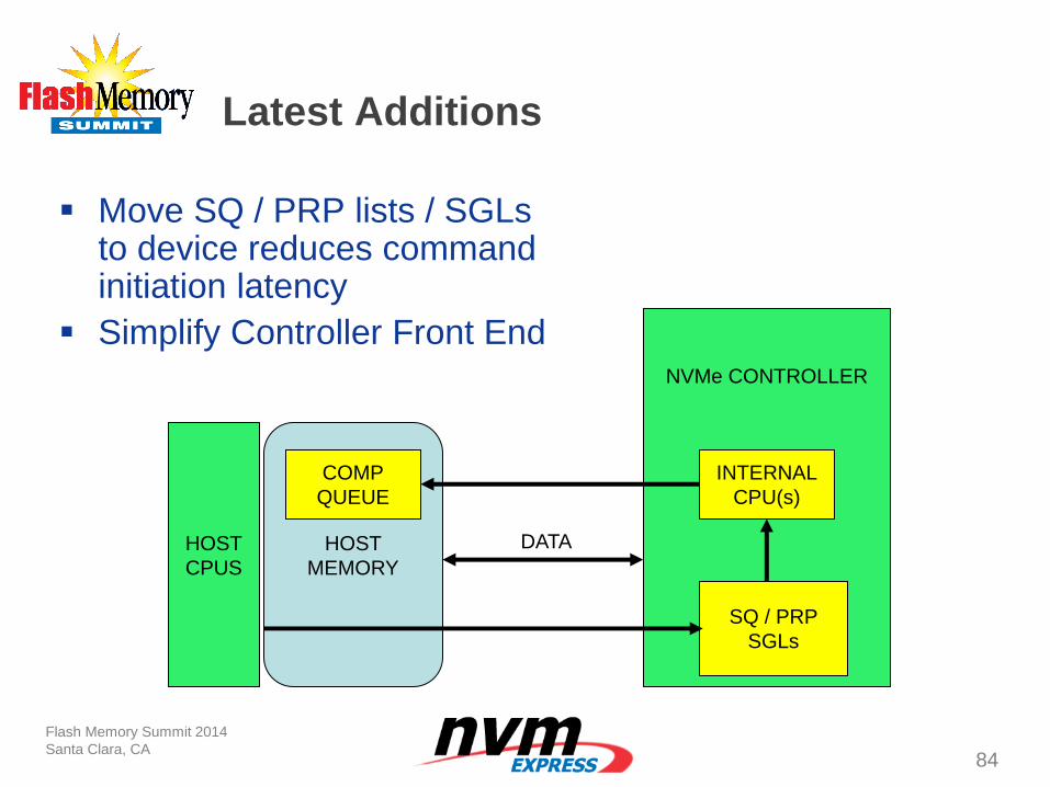
Move SQ / PRP lists / SGLs to device reduces command initiation latency
Simplify Controller Front End
HOST
CPUS
HOST
MEMORY
NVMe CONTROLLER
COMP
QUEUE
SQ / PRP
SGLs
INTERNAL
CPU(s)
DATA
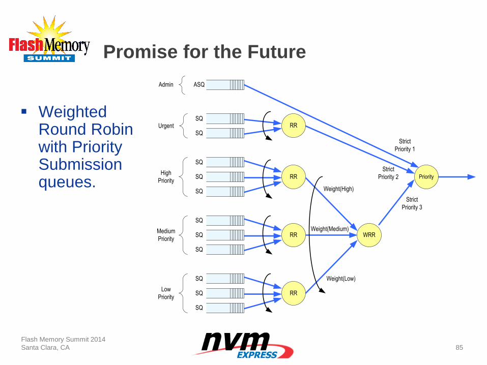
Promise for the Future
Flash Memory Summit 2014
Santa Clara, CA
85
Weighted
Round Robin with Priority Submission queues.
ASQ
SQ
SQ
SQ
RR
SQ
SQ
SQ
RR
SQ
SQ
SQ
RR
WRR
Priority
Weight(High)
Admin
High
Priority
Medium
Priority
Low
Priority
Weight(Medium)
Weight(Low)
Strict
Priority 2
SQ
SQ
RRUrgent
Strict
Priority 3
Strict
Priority 1
Promise for the Future
Flash Memory Summit 2014
Santa Clara, CA
86
I/O Command Prioritization
Today Applications cannot tell the driver the priority of a given command.
Once they can, The NVMe Weighted Round Robin with Priority arbitration can meter commands into the Controller and keep lower priority commands in the Host memory
OS Challenge: Deliver application I/O priority from the application through to the driver
Promise for the Future –
NVMe Specification evolution
Flash Memory Summit 2014
Santa Clara, CA
87
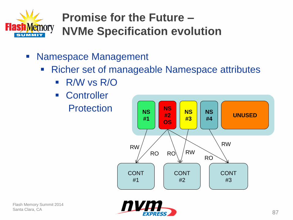
Namespace Management
Richer set of manageable Namespace attributes
R/W vs R/O
Controller
Protection
NS
#1
NS
#2
OS
NS
#3
NS
#4 UNUSED
CONT
#1
CONT
#2
CONT
#3
RW RO RO
RO
RW
RW
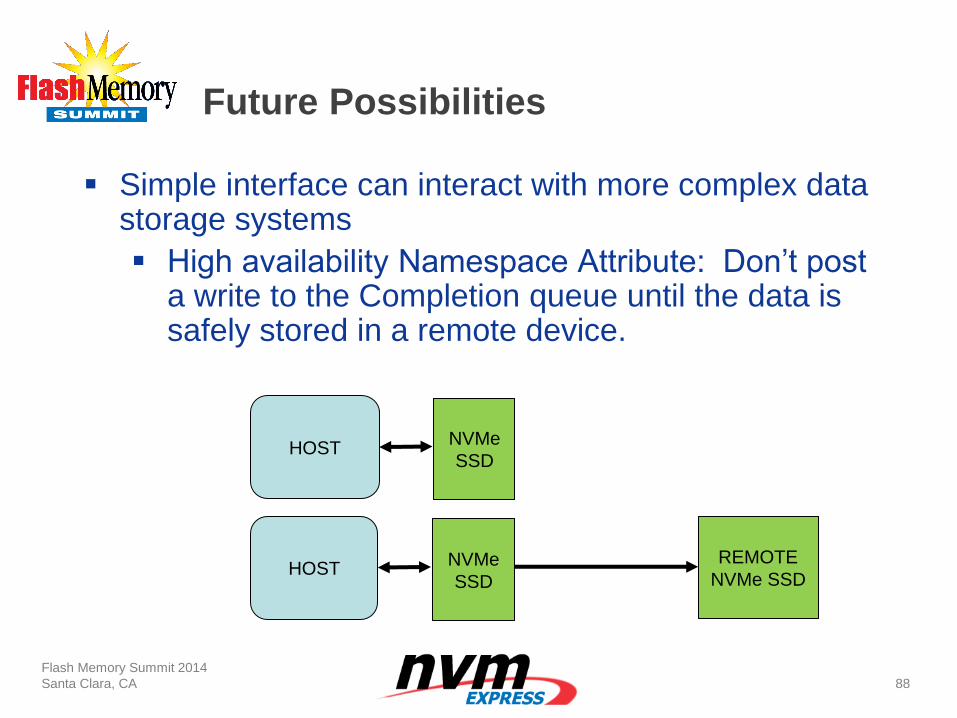
Future Possibilities
Flash Memory Summit 2014
Santa Clara, CA
88
Simple interface can interact with more complex data storage systems
High availability Namespace Attribute: Don’t post a write to the Completion queue until the data is safely stored in a remote device.
HOST
HOST NVMe
SSD
NVMe
SSD
REMOTE
NVMe SSD
Future Possibilities
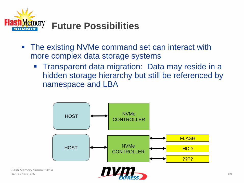
Flash Memory Summit 2014
Santa Clara, CA
89
The existing NVMe command set can interact with more complex data storage systems
Transparent data migration: Data may reside in a hidden storage hierarchy but still be referenced by namespace and LBA
HOST
HOST NVMe
CONTROLLER
NVMe
CONTROLLER
FLASH
HDD
????
Potential for the far future
Flash Memory Summit 2014
Santa Clara, CA
90
Namespaces as files:
• File system should resolve naming, protection, and gross device utilization, but not micro allocate storage within files.
• The controller is always shuffling data around, let it allocate the blocks and communicate about subsystem “fullness” back to the file system as needed.
Thanks
Flash Memory Summit 2014
Santa Clara, CA
91
Come see HGST’s NVMe
technology demo in the NVMe
Booth