numericalmodellingofimpactfractureof ...yadda.icm.edu.pl/yadda/element/bwmeta1.element... · the...
TRANSCRIPT

JOURNAL OF THEORETICAL
AND APPLIED MECHANICS
49, 3, pp. 599-619, Warsaw 2011
NUMERICAL MODELLING OF IMPACT FRACTURE OF
CORTICAL BONE TISSUE USING X-FEM
Adel A. Abdel-Wahab
Vadim V. Silberschmidt
Loughborough University, Wolfson School of Mechanical and Manufacturing Engineering,
Loughborough, Leicestershire, UK
e-mail: [email protected]; [email protected]
A cortical bone tissue is susceptible to fracture that can be caused byevents, such as traumatic falls, sports injuries and traffic accidents. Aproper treatment of bones and prevention of their fracture can be sup-ported by in-depth understanding of deformation and fracture behaviourof this tissue in such dynamic events. Parameters such as damage initia-tion under impact, damage progression and impact strength can help toachieve this goal. In this paper, Extended Finite-Element Method (X-FEM) implemented into the commercial finite-element software Abaqusis used to simulate the actual crack initiation and growth in a cantileverbeam of cortical bone exposed to quasi-static and impact loading usingthe Izod loading scheme. Izod tests were performed on notched bonespecimens of bovine femur to measure its impact strength and to valida-te simulations. The simulation results show a good agreement with theexperimental data.
Key words: cortical bone, impact, X-FEM, finite-element, fracture
1. Introduction
Bone is the principal structural component of a skeleton: it assists the load-bearing framework of a living body. Bone fractures have significant health,economic and social consequences. Both healthy and unhealthy bones are su-sceptible to fracture as a result of low- or high-energy trauma. High-energytraumas are usually linked to car or cycling accidents, while low-energy trau-mas often occur in contact sports. In both cases they are caused by dynamicloading. Factors such as mass, material properties and geometry of bone aswell as the magnitude and orientation of applied loads affect its response to
600 A.A. Abdel-Wahab, V.V. Silberschmidt
such loading. Bones are fractured when they are exposed to severe loads that,in their turn, generate stresses exceeding its ultimate strength. Thus, a frac-ture event occurs initially at the material level that eventually affects theload-carrying capacity of the whole bone at its structural level (Cullinane andEinhorn, 2002). It is worth mentioning here that bone is a viscoelastic mate-rial. Therefore, this type of mechanical behaviour has to be considered whendealing with dynamic events, such as impact.By developing adequate numerical models capable of predicting and de-
scribing bone deformation and fracture behaviour, a detailed study of reasonsfor, and ways to prevent bone fracture could be performed. To plan preven-tion therapies and treatment strategies, scientific knowledge of bone fracturemechanisms is also needed. From the experimental point of view, the impactresistance of the cortical bone tissue did not get enough attention in the lite-rature though it is essential for activities such as jumping and running as wellas protecting internal organs from impact as in the case of skull and ribs (Leeet al., 2011). Still, numerous previous studies have been devoted to analysisof quasi-static mechanical properties and resistance to fracture of the corticalbone tissue. For instance, Augat and Schorlemmer (2006) demonstrated therole of structural properties of cortical bone and its microstructure in its com-petence. Another study, by Bonney et al. (2011), was devoted to investigationof local variations in mechanical properties of cortical bone (porcine femur).Also, various experimental studies investigating the effect of structural pro-perties of cortical bone and its mechanical properties have been conducted(Zioupos, 1998; Zioupos et al., 1999; Wachter et al., 2002; Currey, 2004; Kulinet al., 2010). They dealt with acquisition of the respective data at differentlevels of the bone hierarchical structure – macroscopic and microscopic – usingdifferent methodological approaches. From the fracture mechanics perspective,a review of the structure and properties of bone focusing on mechanical anddeformation behaviour at different length scales was introduced by Launey etal. (2010). In another study, Nalla et al. (2005) analysed the nature of localcracking events that preceded catastrophic fracture of human cortical boneand their relation to the microstructure. Zioupos et al. (2008) studied a re-lation between the strain rate and the microcracking damage in the fractureprocess of human cortical bone in tensile failure. According to dynamic proper-ties of this tissue, only few studies paid attention to that issue. For instance,both dynamic and static material properties of human femur were investigatedusing, respectively, a split Hopkinson bar technique and tests with a universaltesting machine (Katsamanis and Raftopoulos 1990). The average dynamicYoung modulus of 19.9GPa was found to be 23% greater than that for staticloading – 16.2GPa. In terms of bone impact characteristics, only preliminary

Numerical modelling of impact fracture... 601
data are available (Panagiotopoulos et al., 2005), with a Charpy impact testused to measure the energy absorbed by strips cut from proximal femur. Ina related experimental work, employing an Izod impact tester, Kovan (2008)investigated the absorbed energy and the impact strength of a mandible atdifferent positions. In our previous work, the impact properties of a corticalbone tissue were investigated using Izod tests for different cortex position ofbovine femur (Abdel-Wahab et al., 2010). The obtained experimental resultsemphasised that bovine femur cortical bone had a nearly uniform fractureenergy character with regard to the cortex position. In addition, a 2D finite-element model to simulate the test and capture its behaviour up to fracturewas developed. In that model, the behaviour of three different constitutivematerial models – linear-elastic, elastic-plastic and viscoelastic – based on ourprevious experiments (Abdel-Wahab et al., 2011) were compared. It was foundthat the viscoelastic model showed a good agreement with the experimentaldata.
In other experiments, Lee et al. (2011) tested non-mineralized and mine-ralized materials, such as cortical bone utilizing a drop-weight test to investi-gate the impact strength along with the impact damage. In a similar study,longitudinal human cortical specimens were tested in a tensile impact testerat a strain rate of 133 s−1 (Saha and Hayes, 1976). A marked non-linearitywas observed in the stress-strain behaviour, including plastic deformation andstrain-hardening effects. The mean tensile impact strength and impact energywere 126.3 ± 33.1MPa and 18790 ± 7355 J/m2, respectively.
Often, in-vivo bone fracture is initiated and promoted by cracks; therefo-re, fracture mechanics is used as an important tool to assess its strength andfracture toughness and to improve the diagnoses and treatment of bone fractu-res (Wang and Puram, 2004). Up to now, Linear-Elastic Fracture Mechanics(LEFM) was mostly used to assess the toughness of cortical bone tissue; ityields a single-valued fracture parameter – the critical stress intensity factoror the critical strain energy release rate (Norman et al., 1995, 1996). Due tocomplex composition and microstructure of the cortical bone tissue, it has se-veral toughening mechanisms, such as diffuse microcracking, crack deflection,and fibre bridging (Zioupos, 1998; Vashishth et al., 2000; Yeni and Norman,2000; Nalla et al., 2004). The inadequacy of LEFM theory application to de-scribe cortical bone tissue fracture was raised due to observed resistance curve(R-curve) behaviour (Lucksanasombool et al., 2001; Ural and Vashishth, 2006).Therefore, cohesive zone models were used to analyse the initiation and pro-pagation of cortical bone cracks (Ural and Vashishth, 2006; Yang et al., 2006;Cox and Yang, 2007). In a recent study, Morais et al. (2010) demonstrated the
602 A.A. Abdel-Wahab, V.V. Silberschmidt
adequacy of a Double-Cantilever Beam (DCB) test for determining fracturetoughness under pure mode-I loading of cortical bone by implementing a newdata-reduction scheme based on specimen compliance.
Despite this body of research, experimental and numerical studies of thedynamic behaviour of a cortical bone tissue attracted less attention. Therefore,this study comprises two parts covering experimental and numerical aspectsof such analysis. Still, analysis of the actual crack initiation and growth washard to achieve using the mentioned approaches in simulations. With the newExtended Finite-Element Method (X-FEM), crack initiation and propagationcan be modelled more easily. Thus, the aim of this study is to develop andvalidate a numerical model for analysis of fracture behaviour of the corticalbone tissue under impact and quasi-static loading using X-FEM.
2. Materials and methods
2.1. Specimen preparation
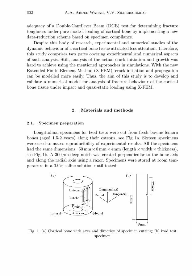
Longitudinal specimens for Izod tests were cut from fresh bovine femorabones (aged 1.5-2 years) along their osteons, see Fig. 1a. Sixteen specimenswere used to assess reproducibility of experimental results. All the specimenshad the same dimensions: 50mm×8mm×4mm (length×width× thickness),see Fig. 1b. A 300 µm-deep notch was created perpendicular to the bone axisand along the radial axis using a razor. Specimens were stored at room tem-perature in a 0.9% saline solution until tested.
Fig. 1. (a) Cortical bone with axes and direction of specimen cutting; (b) izod testspecimen

Numerical modelling of impact fracture... 603
2.2. Izod test
An amount of energy absorbed during a suddenly applied force can be qu-antified with impact tests of materials; the required data about deformationand failure of materials during high-strain-rate loading cannot be determi-ned using quasi-static fracture tests. Impact testing is usually performed withCharpy or Izod test machines. An Izod test system incorporates a swingingpendulum (hammer) that impacts a notched specimen fixed in a cantilever-beam position with the notch facing the hammer (Lee et al., 2011). In ourstudy, impact tests were carried out using a CEAST Resil Impactor. In thetests, the bottom half of the specimen was fixed firmly in the machine vice anda knife-edge wedge was used to define the notch position. The upper half of thespecimen was struck by a pendulum hammer with a controlled level of energy.The distance between the notch and the position of hammer strike was stan-dard – 22mm. In this study, a calibrated hammer with a mass of 0.6746 kgand 0.3268m long was used. The maximum nominal hammer energy of 2 Jcorresponds to the striking position of 150◦ resulting in an impact velocityof 3.46m/s. The level of initial energy can be varied by changing the initialangle of the hammer. The energy level used in this study was 0.5 J that corre-sponded to the initial angle of 58◦. A piezoelectric force transducer was fixedrigidly to the hammer to capture the impact-force signal. When the pendulumis released from the pre-defined angle, its impact with the specimen generatesa change in electrical resistance of the piezoelectric sensor that is captured bythe data acquisition system – DAS 8000 – connected to the impactor.
2.3. Numerical model
2.3.1. Extended finite element method
X-FEM is a numerical method that enables analysis of crack propagationwithout remeshing a cracked specimen in accordance to newly created crackfaces. It employs a local enrichment of the approximation areas. The methodcan be useful for evolving processes with non-smooth characteristics in smallparts of a computational domain, e.g. near discontinuity or singularity regions,as in the case of cracks for which the standard finite element method is not ac-curate. The X-FEM was first introduced by Belytschko and Black (1999). Theenrichment is realised based on the partition-of-unity concept developed byMelenk and Babuska (1996); it allows incorporation of local enrichment func-tions into a finite-element approximation domain. Spatial enrichment functionswith additional degrees of freedom ensure account for discontinuities. The ge-neral framework of this method is incorporated in the finite- element softwareAbaqus 6.10 (2010).

604 A.A. Abdel-Wahab, V.V. Silberschmidt
2.3.2. Geometry, mesh, and boundary conditions
In this study, three finite-element models (FEM) were developed: Model A,Model B, and Model C. Model A is a 2D X-FEM model used to simulate thefracture of cortical bone exposed to impact loading in the Izod test, see Fig. 2.Model B is a 3D formulation of Model A, whereas Model C is a 3D X-FEMmodel for quasi-static fracture analysis. The impact tests were simulated withthe finite-element software Abaqus 6.10/Implicit using Models A and B toverify the applicability of the X-FEM to analysis of the failure behaviour ofthe cortical bone tissue under impact-loading conditions. In addition, Model Cwas developed to elucidate fracture development in the cortical bone tissueunder different loading conditions. A full description of Model A can be foundin our previous work (Abdel-Wahab et al., 2010); however, in that work onlythe behaviour up to failure was studied. Figure 2 shows its geometry and meshformulation.
Fig. 2. (a) Real hammer; (b) Model A; (c) hammer-specimen interaction and mesharound the notch
In Model B, the real geometry and masses of the hammer and specimenwith a 300µm notch were used (see Fig. 3). In Abaqus 6.10, a kinematic co-upling constraint is used to transmit rotation to the structure while permittingradial motion. Hence, this feature was employed to constraint the hammer fromradial or translational movements except around one axis only; it is z-axis inour case. To get the exact movement of the hammer, as it happens in reality,

Numerical modelling of impact fracture... 605
all the nodes of the surface of the inner cylinder of the upper block of thehammer were kinematically coupled to a reference point at the middle of thatcylinder, then the reference point was restrained to translate along x, y, and zand to rotate around x or y axes. The reference point was only free to rotatearound the z-axis. Two sets were defined: the reference point (set1) and theinner surface (set2). The following equation was used to define the couplingbetween those sets
ur1 − ur2 = 0 (2.1)
where ur1 and ur2 are the rotational degrees of freedom for set1 and set2,respectively.
Fig. 3. (a) Setup of Izod test; (b) Model B; (c) hammer-specimen interaction;(d) Meshing of hammer and specimen (specimen is increased)
On the other hand, two surfaces were chosen to define a surface-to-surfacecontact between the specimen and the hammer. These surfaces are shown asS1 and S2 in Fig. 3d. The master surface was chosen to be S2 with S1 chosen tobe the slave one. The mesh of the master surface was adjusted to be finer thanthat of the slave surface. A finite sliding with frictionless tangential behaviourformulation was chosen between the two surfaces. To reduce the computationtime, the hammer was assembled very close to the specimen as the initialposition in simulations. An angular velocity of 5.33 rad/s – around the x-axis– corresponding to the initial angle of 58◦ (initial energy of 0.5 J) was applied

606 A.A. Abdel-Wahab, V.V. Silberschmidt
to the hammer. The support of the specimen was modelled as rigid; all degreesof freedom of the specimen bottom part were constrained (see Figs. 3b). Lineartetrahedron (C3D4) elements were used for both specimen and hammer; it iscurrently the only element type that can be used for 3D X-FEM analysis.A total number of 53113 elements and 10967 nodes for the bone specimenand 23695 elements and 6871 nodes for the hammer were used. The force dueto contact pressure between the piezoelectric force sensor and counterpart ofthe specimen was recorded in the history output of the finite-element softwareAbaqus/Implicit. Also, the status of the X-FEM that shows the crack path wasused as an output along with the distributions of stress and strain componentsand their principal values.
In order to compare the fracture behaviour of the cortical bone specimenunder quasi-static and impact loading, Model C was developed, Fig. 4. It con-sists of a cantilever-beam specimen of cortical bone with the same geometry,mesh and material properties as Model B. In Model C, the hammer was exclu-ded from the analysis and, instead, a displacement-controlled load of 2mm wasapplied at the same position of the hammer-specimen interaction, see Fig. 4b.
Fig. 4. (a) Meshed 3D quasi-static specimen; (b) applied displacement and boundaryconditions of 3D quasi-static model
2.3.3. Material properties
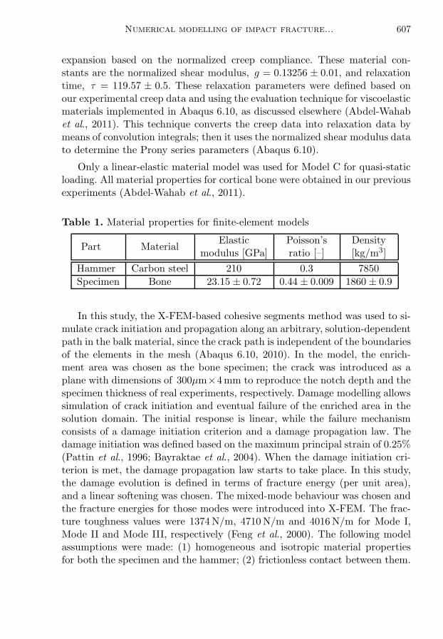
Elastic material properties for the hammer and cortical bone tissue usedin the numerical simulations are given in Table 1. The viscous behaviourof bones was introduced into models A and B in terms of the Prony series
Numerical modelling of impact fracture... 607
expansion based on the normalized creep compliance. These material con-stants are the normalized shear modulus, g = 0.13256 ± 0.01, and relaxationtime, τ = 119.57 ± 0.5. These relaxation parameters were defined based onour experimental creep data and using the evaluation technique for viscoelasticmaterials implemented in Abaqus 6.10, as discussed elsewhere (Abdel-Wahabet al., 2011). This technique converts the creep data into relaxation data bymeans of convolution integrals; then it uses the normalized shear modulus datato determine the Prony series parameters (Abaqus 6.10).
Only a linear-elastic material model was used for Model C for quasi-staticloading. All material properties for cortical bone were obtained in our previousexperiments (Abdel-Wahab et al., 2011).
Table 1. Material properties for finite-element models
Part MaterialElastic Poisson’s Density
modulus [GPa] ratio [–] [kg/m3]
Hammer Carbon steel 210 0.3 7850
Specimen Bone 23.15 ± 0.72 0.44 ± 0.009 1860 ± 0.9
In this study, the X-FEM-based cohesive segments method was used to si-mulate crack initiation and propagation along an arbitrary, solution-dependentpath in the balk material, since the crack path is independent of the boundariesof the elements in the mesh (Abaqus 6.10, 2010). In the model, the enrich-ment area was chosen as the bone specimen; the crack was introduced as aplane with dimensions of 300µm×4mm to reproduce the notch depth and thespecimen thickness of real experiments, respectively. Damage modelling allowssimulation of crack initiation and eventual failure of the enriched area in thesolution domain. The initial response is linear, while the failure mechanismconsists of a damage initiation criterion and a damage propagation law. Thedamage initiation was defined based on the maximum principal strain of 0.25%(Pattin et al., 1996; Bayraktae et al., 2004). When the damage initiation cri-terion is met, the damage propagation law starts to take place. In this study,the damage evolution is defined in terms of fracture energy (per unit area),and a linear softening was chosen. The mixed-mode behaviour was chosen andthe fracture energies for those modes were introduced into X-FEM. The frac-ture toughness values were 1374N/m, 4710N/m and 4016N/m for Mode I,Mode II and Mode III, respectively (Feng et al., 2000). The following modelassumptions were made: (1) homogeneous and isotropic material propertiesfor both the specimen and the hammer; (2) frictionless contact between them.
608 A.A. Abdel-Wahab, V.V. Silberschmidt
3. Results and discussion
The fracture behaviour of bone is closely coupled to its underlying hierarchicalstructure; therefore, the measured fracture parameters depend on the lengthscale at which they are measured. Moreover, in order to correctly assess thecracking and fracture behaviour of bone, the crack direction should be clini-cally relevant, i.e. cracks propagating in the transverse direction and involverealistic flaw sizes (Koester et al., 2008). Accordingly, in the experiment partof this study, two groups of specimens were tested: the first group consistsof specimens with 300 µm notch and second group consists of specimens with600µm notch. For all the specimens the notch was generated perpendicularto the osteons, see Fig. 1a. The chosen notch sizes were below 600 µm accor-ding to the physiological pertained flaw size reported by Koester et al. (2008).As our quasi-static tests on cortical bone demonstrated (Abdel-Wahab et al.,2011) and as well-known from the literature, the cortical bone properties va-ry from one cortex position to another due to variation in both compositionand microstructure. Thus, impact strength was measured for specimens cutfrom different cortex positions called anterior, posterior, medial and lateral,see Fig. 1a. Figure 5 shows a comparison for data obtained for these positionsfor 300µm- and 600 µm-notched specimens; the initial energy level used inthose tests was 0.5 J. The impact strength was measured as the absorbed im-pact energy divided by the un-notched cross sectional area of the specimen.The obtained results show that for the same applied energy level and cortexposition, the notch size has a negative effect on impact strength of the corticalbone tissue. In general – apart from the medial cortex position with nearlythe same average impact strength for both notch sizes – the specimens not-ched with 300µm required higher energy per unit area to fail compared tothose with 600 µm notch. Statistically, the average impact strength requiredto produce fracture appears to be higher at the lateral position, with diffe-rent magnitudes for different notch sizes. However, considering the spread ofthe mean impact energy for all cortex positions and notch depths, it is appa-rent that it is within the interval from 6 kJ/m2 to 12 kJ/m2. The statisticalanalysis for cortex positions revealed no significant difference of the mean im-pact strength for both notch depths for 300µm (p = 0.862) and for 600µm(p = 0.354). Also, checking the combined effect of both factors – cortex posi-tion and notch depth – on the mean impact strength no significant differencewas demonstrated (p = 0.642). Based on these results, bovine femur seemsto have a nearly uniform impact strength. The obtained values for the im-pact strength are in a good agreement with other studies in the literature;for instance, using four-point bending setup, bovine cortical bones were found

Numerical modelling of impact fracture... 609
to have an impact strength in the range of approximately 6-24 kJ/m2 (Reillyand Currey, 2000). In a separate study, the impact strength of bovine corticalbone was found to be 10 kJ/m2 in drop-weight-tower tests (Lee et al., 2010).The obtained impact strength results of our study agree well with those in theliterature, even based on different techniques.
Fig. 5. Impact strength of longitudinal cortical bone specimens for different cortexpositions and two different notch sizes
Below, results of simulations with Models A, B and C of the fracture beha-viour of cortical bone tissue under impact and quasi-static loading are presen-ted in comparison with experimental data. The contact-force profile obtainedin our Izod tests of cortical-bone specimens was used to validate the develo-ped finite-element models A and B. A comparison of the experimental resultswith simulation ones (Fig. 6) demonstrates that Model A reproduces transientfracture behaviour of the cortical bone tissue. However, Model B, though sho-wing a good agreement both with Model A and the experimental results untilits termination point, results in an unrealistic fracture scenario afterwards aswill be discussed below. Some deviations from the experimental results can belinked to different factors that are not incorporated into the current stage ofmodel development. Among them, there is a complex hierarchical structure,anisotropy, and heterogeneity of the cortical bone tissue contributing to itsfracture behaviour. Undoubtedly, as a consequence of composition and micro-structure, there are several experimentally observed toughening mechanismsin the fracture process of cortical bone tissue, such as diffuse microcracking,crack deflection and fibre bridging (Zioupos, 1998; Vashishth et al., 2000; Nallaet al., 2004) that can affect propagation of the crack.
It was also noticed that the cortical bone specimen failed in tests catastro-phically in a brittle manner as soon as the maximum force was reached; it is

610 A.A. Abdel-Wahab, V.V. Silberschmidt
Fig. 6. Comparison of evolution of contact force in impact loading (notchsize 300µm)
Fig. 7. Evolution of contact force and normalized crack length in Model A (notchsize 300µm)
presented by a nearly vertical line in Fig. 6 after the peak. In the simulationresults of Model A, see Fig. 7, specimen fracture is represented in terms of anormalized crack length (Lcr/(W −Lnotch)) against time. It was calculated asthe length of the crack (Lcr) divided by the un-notched width (W − Lnotch)measured on the specimen surface. At the beginning, the crack started to evo-lve slowly up to approximately 10% of this width at t = 0.2ms, then grewsteeply up to the contact force peak (331.3 N at t = 0.36ms) at which only30% of the specimen failed. However, even when the force started to decline;it was still high enough to propagate the crack. The crack growth accelera-

Numerical modelling of impact fracture... 611
ted after the maximum force position up to the specimen failure point, withthe crack spending only 0.28ms to reach the opposite side of the specimen.Obviously, at the moment of complete failure of the specimen, the contactforce vanished.For Model A, the STATUSXFEM output – available in Abaqus 6.10 –
shows the crack evolution during the course of analysis. This parameter variesover the range between 0 and 1; when it equals to 0 there is no damage andin the case of complete failure, it equals 1. Figure 8 shows the evolution ofthe crack originating from the notch and propagating across the width of thespecimen towards the opposite side.
Fig. 8. Crack evolution at different time increments (Model A)
It was noticed that the crack started to propagate immediately along aninclined plane, with the notch root indicating mixed-mode fracture behaviour(Mode I and Mode II). That was followed by a small horizontal crack path.These changes in the crack path direction correspond to kinks in the first partof the contact force-time curve up to the contact-force peak, see Fig. 7. Obvio-usly, from the point of view of the beam theory, the studied cantilever beam isexposed to two types of stresses: normal stress (bending) and transverse shearstress. In these models, the beam span-to-width ratio is 2.2; so the transverseshear stresses should be significant. It was found that the shear stress levelwas comparable to that of normal ones (Figs. 9 and 10). Also, a transversedistribution of shear stress is parabolic across the width of the cantilever anduniform from the position of specimen-hammer interaction up to the notchlocation, see Fig. 9. This stress state causes Mode II fracture. On the otherhand, normal stress S22 in the y-direction causes Mode I fracture behaviour.Therefore, immediately after the impact takes place and at the notch root,only Mode I fracture took place due to vanishing (or very small) shear stres-ses. At the neutral plane of the cantilever, where the shear stress has its peak

612 A.A. Abdel-Wahab, V.V. Silberschmidt
while the bending stress vanishes, Mode II dominates fracture. The oppositeside of the beam was under compression, with shear stress vanishing. Thus,between the notch side and/or the opposite side and the neutral plane, bothModes I and II took place. When the crack started to propagate, it causedstresses redistribution resulting in a complex crack path; this can be seen inFig. 11.
Fig. 9. Distribution of shear stress S12 in Model A (a), Model B (b) and Model C (c)
Fig. 10. Distribution of normal stress S22 in Model A (a), Model B (b) andModel C (c)
While both Models A and C showed one main crack that originated fromthe notch and propagated in the depth and width of the specimen towards theopposite face (Figs. 11a and 11c), Model B demonstrated a band of randomshort cracks around the notched area of the specimen with no major crackpercolating the specimen. In this model, due to the impact load suddenlyapplied to the specimen, elastic stress-waves were generated, propagating in

Numerical modelling of impact fracture... 613
different directions in the specimen activating all fracture modes and initiatingmultiple cracks. As elastic waves keep moving and reflecting in a complexway inside the specimen, a band of damaged zone was formed instead of asingle crack demonstrating limitations of the current 3D X-FEM routine ofAbaqus 6.10 with respect to dynamic cracking problems (Fig. 11b). On theother hand, in Model C, a single crack propagated from the root of the notch tothe opposite side of the specimen. That crack path was similar to that observedin the experiment, see Fig. 11d. Still, the effect of underlying heterogeneousmicrostructure, such as pores and weak interfaces – cement lines – between theosteons and interstitial matrix that can deflect the crack (Nalla et al., 2004),can be responsible for some deviations from the solution obtained with theused isotropic homogeneous formulation.
Fig. 11. Distributions of maximum principal strain in Model A (a), Model B (b) andModel C (c). (d) Final crack path in Izod-test specimen
The damage initiation and evolution behaviour for Models A and C areshown in Fig. 12. In this figure, the linear component of displacement in thex-direction at the contact position is obtained from Abaqus and used as anexternal parameter for the axis of abscissas. Apparently, damage started im-mediately as the beam was subjected to the load. In addition, at the samedeformation level, the crack length in Model C was larger than that in Mo-del A. It is worth recalling that a linear elastic material model was assignedto the quasi-static model (Model C), whereas a viscoelastic material modelwas used in the impact models (Models A and B). Hence, different behaviourcould be due to activated relaxation mechanisms that assisted to damp someof the applied energy of the hammer and resulted in differences between tworesults. However, at the beginning up to 0.15mm both cases are close; at thisstage both models still behave elastically. Apparently, the current 3D X-FEMroutine in Abaqus 6.10 causes some convergence problems even in quasi-static

614 A.A. Abdel-Wahab, V.V. Silberschmidt
formulations: simulations with Model C terminated before the crack reachedthe opposite side (at the normalized length of about 0.75 (Fig. 12). Model Adid not demonstrate such a problem. By investigating a through-thickness va-riation in the crack length for Model C, its front demonstrated a non-uniformcharacter (Fig. 13) changing with displacement. Due to the stress state vary-ing across the thickness, the crack propagates with a different rate at variouspositions along its front.
Fig. 12. Evolutions of crack length for Models A and C
Fig. 13. Crack length variation along its front in Model C

Numerical modelling of impact fracture... 615
A direct measurement of crack length as a function of time and/or defor-mation is not available in Abaqus 6.10; therefore various images at differenttime increments were taken and measured using Image Pro-Express softwa-re (Image-Pro Express 2005). The crack propagation rate for Model A wasobtained by differentiation of the curve-fit equation for the crack length. Figu-re 14 shows both parameters as a function of time. Since the crack length hasa quadratic curve-fit equation, the crack growth rate shows a linear increasewith time. At t = 0, the specimen was exposed to a sudden impact with thehammer with the initial velocity of 1.74m/s, causing an initial crack propa-gating rate of 2.054m/s. This rate has evolved during the fracture process ofthe specimen to reach 19.5m/s at the final percolation of the specimen.
Fig. 14. Evolution of crack length and crack propagation rate in Model A
4. Conclusions
Crack initiation and growth under quasi-static and impact loading of corticalbone tissue were studied using experimental and numerical simulations. Izodtests were performed to characterise its impact strength for different cortexpositions. Three different finite-element models – Models A, B, and C – wereimplemented into the commercial finite-element software Abaqus 6.10 usingits implicit solver. A series of simulations was performed to study the crack in-itiation and propagation under quasi-static and impact loading. The obtainednumerical results were quite close to the experimental ones, and the numeri-cal models have the capability to reproduce the failure of cortical bone tissueunder both impact and quasi-static loading. The finite-element results provi-

616 A.A. Abdel-Wahab, V.V. Silberschmidt
de more detailed information than the experimental tests and helped to gaina better understanding of the fracture behaviour of the cortical bone tissue.Numerical simulations showed that its fracture behaviour was reasonably wellpredicted using Model A in terms of the contact force profile and the crackpath, while Model B exhibited unrealistic fracture scenario: formation of adamage band with multiple cracks across the specimen width and thicknessaround the notch area. The stress state generated by the applied load triggeredModes I and II in the fracture process of the bone specimen in the Izod testsetup. In general, the results showed the suitability of the developed numericalapproach to study the fracture of cortical bone tissue under quasi-static andimpact loading.
References
1. Abaqus 6.10, 2010, Analysis user’s manual, Section 10.6.1
2. Abdel-Wahab A.A., Maligno A., Silberschmidt V.V., 2010, Dynamicproperties of cortical bone tissue: Izod tests and numerical study, Comput.Mater. Continua, 19, 3, 217-238
3. Abdel-Wahab A.A., Alam K., Silberschmidt V.V., 2011, Analysis of ani-sotropic viscoelastoplastic properties of cortical bone tissues, J. Mech. Behav.Biomed. Mater., DOI.org/10.1016/j.jmbbm.2010.10.001
4. Augat P., Schorlemmer S., 2006, The role of cortical bone and its micro-structure in bone strength, Age Ageing, 35-s2, ii27-ii31
5. Bayraktae H.H., Morgan E.F., Niebur G.L., Morris G.E., WongE.K., Keaveny T.M., 2004, Comparison of the the elastic and yield pro-perties of human femoral trabecular and cortical bone tissue, J. Biomech., 37,27-35
6. Belytschko T., Black T., 1999, Elastic crack growth in finite elements withminimal remeshing, Int. J. Numer. Meth. Eng., 45, 5, 601-620
7. Bonney H., Colston B.J., Goodman A.M., 2011, Regional variation in themechanical properties of cortical bone from the porcine femur, Med. Eng. andPhys., 33, 4, 513-520
8. Cox B.N., Yang Q., 2007, Cohesive zone models of localization and fracturein bone, Eng. Fract. Mech., 74, 1079-1092
9. Cullinane D.M., Einhorn T.A., 2002, Biomechanics of bone, [In:] Principlesof Bone Biology, Bilezikian J.P., Raisz L.G., Rodan A.R. (Edit.), San Diego,USA, Academic Press, 1

Numerical modelling of impact fracture... 617
10. Currey J.D., 2004, Tensile yield in compact bone is determined by strain,post yield behaviour by mineral content, J. Biomech., 37, 549-556
11. Feng Z., Rho J., Ziv I., 2000, Orientation and loading condition dependenceof fracture toughness in cortical bone, Mater. Sci. Eng. C, 11, 41-46
12. Katsamanis F., Raftopoulos D.D., 1990, Determination of mechanical pro-perties of human femoral cortical bone by the Hopkinson bar stress technique,J. Biomech., 23, 11, 1173-1184
13. Koester K.J., Ager III J.W., Ritchie R.O., 2008, The true toughness ofhuman cortical bone measured with realistically short cracks, Nat. Mater., 7,672-677
14. Kovan V., 2008, An assessment of impact strength of the mandible, J. Bio-mech., 41, 16, 3488-3491
15. Kulin R.M., Jiang F., Vecchio K.S., 2010, Effects of age and loading rateon equine cortical bone failure, J. Mech. Behav. Biomed. Mater., 4, 1, 57-75
16. Launey M.E., Buehler M.J., Ritchie R.O., 2010, On the mechanisticorigins of toughness in bone, Ann. Rev. Mater. Res., 40, 25-53
17. Lee S., Novitskaya E.E., Reynante B., Vasquez J., Urbaniak R., Ta-kahashi T., Woolley E., Tombolato L., Chen Po-Yu, McKittrick J.,2011, Impact testing of structural biological materials, Mater. Sci. Eng. C, 31,4, 730-739
18. Lucksanasombool P., Higgs W.A.J., Higgs R.J.E.D., Swain M.V.,2001, Fracture toughness of bovine bone: influence of orientation and stora-ge media, Biomater., 22, 3127-3132
19. Melenk J. M., Babuska I., 1996, The partition of unity finite element me-thod: basic theory and applications, Comput. Method Appl. Math., 39, 289-314
20. Morais J.J.L., de Moura M.F.S.F., Pereira F.A.M., Xavier J., Do-urado N., Dias M.I.R., Azevedo J.M.T., 2010, The double cantilever beamtest applied to mode I fracture characterization of cortical bone tissue, J. Mech.Behav. Biomed. Mater., 3, 6, 446-453
21. Nalla R.K., Kruzic J.J., Ritchie R.O., 2004, On the origin of the tough-ness of mineralized tissue: microcracking or crack bridging? Bone, 34, 790-798
22. Nalla R.K., Stolken J.S., Kinney J.H., Ritchie R.O., 2005, Fracturein human cortical bone: local fracture criteria and toughening mechanisms, J.Biomech., 38, 1517-1525
23. Norman T.L., Nivargikar S.V., Burr D.B., 1996, Resistance to crackgrowth in human cortical bone is greater in shear than in tension, J. Biomech.,29, 1023-1031
24. Norman T.L., Vashishth D., Burr D.B., 1995, Fracture toughness of hu-man bone under tension, J. Biomech., 28, 309-320

618 A.A. Abdel-Wahab, V.V. Silberschmidt
25. Panagiotopoulos E., Kostopoulos V., Tsantzalis S., Fortis A.P.,Doulalas A., 2005, Impact energy absorption by specimens from the upperend of the human femur, Injury, 36, 5, 613-617
26. Pattin C.A., Calet W.E., Carter D.R., 1996, Cyclic mechanical propertydegradation during fatigue loading of cortical bone, J. Biomech., 29, 69-79
27. Reilly G.C., Currey J.D., 2000, The effect of damage and microcrackingon the impact strength of bone, J. Biomech., 33, 337-343
28. Saha S., Hayes W.C., 1976, Tensile impact properties of human compactbone, J. Biomech., 9, 4, 243-244, IN5, 245-251
29. Ural A., Vashishth D., 2006, Cohesive finite element modelling of agerelatedtoughness loss in human cortical bone, J. Biomech., 39, 2974-2982
30. V. Image-Pro Express, V.m.c., 2005
31. Vashishth D., Tanner K.E., Bonfield W., 2000, Contribution, develop-ment and morphology of microcracking in cortical bone during crack propaga-tion, J. Biomech., 33, 1169-1174
32. Wachter N.J., Krischak G.D., Mentzel M., Sarkar M.R., EbingerT., Kinzl L., Claes L., Augat P., 2002, Correlation of bone mineral densitywith strength and microstructural parameters of cortical bone in vitro, Bone,3, 90-95
33. Wang X., Puram S., 2004, The toughness of cortical bone and its relationshipwith age, Ann. Biomed. Eng., 32, 123-135
34. Yang Q.D., Cox B.N., Nalla R.K., Ritchie R.O., 2006, Re-evaluatingthe toughness of human cortical bone, Bone, 38, 878-887
35. Yeni Y.N., Norman T.L., 2000, Calculation of porosity and osteonal cementline effects on the effective fracture toughness of cortical bone in longitudinalcrack growth, J. Biomed. Mater. Res. B Appl. Biomater., 51, 504-509
36. Zioupos P., 1998, Recent developments in the study of failure of solid bioma-terials and bone: fracture and prefracture toughness, Mater. Sci. Eng. C, 6,33-40
37. Zioupos P., Currey J.D., 1998, Changes in the stiffness, strength, and to-ughness of human cortical bone with age, Bone, 22, 57-66
38. Zioupos P., Currey J.D., Hamer A.J., 1999, The role of collagen in the dec-lining mechanical properties of aging human cortical bone, J. Biomed. Mater.Res., 45, 108-6
39. Zioupos P., Hansen U., Currey J.D., 2008, Microcracking damage and thefracture process in relation to strain rate in human cortical bone tensile failure,J. Biomech., 41, 14, 2932-2939

Numerical modelling of impact fracture... 619
Modelowanie numeryczne złamania uderzeniem istoty korowej kości za
pomocą rozszerzonej metody elementów skończonych
Streszczenie
Istota korowa kości jest tkanką podatną na złamanie wywołane m.in. takimi zda-rzeniami jak upadki, kontuzje sportowe czy wypadki samochodowe. Odpowiednieleczenie czy profilaktyka stanu kości powinny być wsparte głębokim zrozumieniemzjawisk deformacji i pękania tej tkanki zachodzących podczas takich dynamicznychobciążeń. Znajomość parametrów opisujących inicjację uszkodzenia pod wpływemobciążenia uderzeniowego, progresja tego uszkodzenia i wreszcie odporność na zła-manie może być pomocna w tej praktyce. W prezentowanej pracy przedyskutowanoimplementację rozszerzonej metody elementów skończonych (X-FEM) do standardo-wego i komercyjnego pakietu ABAQUS w celu symulacji faktycznych zjawisk towa-rzyszących inicjacji i propagacji pęknięcia belki wykonanej z materiału oddającegowłaściwości istoty korowej poddanej działaniu quasi-statycznych i uderzeniowych ob-ciążeń, wspartej próbami udarnościowymi Izoda. Testy Izoda zostały przeprowadzonena przygotowanych próbkach z bydlęcej kości udowej z naciętym karbem w celu ekspe-rymentalnej weryfikacji wytrzymałości na uderzenie. Rezultaty badań numerycznychwykazały dobrą zgodność z wynikami tych prób.
Manuscript received March 10, 2011; accepted for print April 29, 2011