nts01 basic design data -...
TRANSCRIPT
Nynas AB (publ) Postal address Office address Telephone Telefax Web Reg No SE-149 82 Nynäshamn Raffinaderivägen +46 8 520 650 00 +46 8 520 176 38 www.nynas.com 556029-2509 Sweden
Project Approval date Page
NYNAS TECHNICAL STANDARD 2010-03-20 1 (40) Document No Approved by Appendix
P99-POCE-00048 PEER 0 Description Subject Version
Basic Design Data NTS01 F NTS01 Basic Design Data Distribution
Dep/Name Resp. Consid. Appr. Nynäshamn: Engineering / Peter Eriksson Engineering / Ulf Davidsson Engineering / Rikard Thelander Reliability / Bengt Oldsberg Production / Cyril Thebault Gothenburg / Helen Ljungqvist
R
C C C C
A
Changes indicated by text in blue and/or by a blue vertical line in the right margin. Changes in Version F: Page 10 3.1 General Requirements
Page 15 5.1.6 PMI Page 18 5.7.1 Standard Page 19 5.8.1 Standard Page 20 5.9.1 Design Code Page 21 5.9.7 Mechanical Seals Page 24 5.15.4 Loop Accuracy
5.15.6 Transmitters 5.15.7 Control Valves
Page 29 6.4.5 Ladders Page 35 10.1.1 General Requirements Page 37 10.5 Base Line Footprint Page 38 11.3.1 Carbon Dioxide CO2 Page 39 13.2 NTS
Subject/Description Appendix Version Approved by Approval date Page
NTS01 0 F PEER 2010-03-20 2 (40) Basic Design Data
Content Section 1 - Meteorological Data Section 2 - Utilities
2.1 Fuel 2.2 Electric Power 2.3 Cooling Water 2.4 Steam 2.5 Water 2.6 Nitrogen 2.7 Air 2.8 Make up Hydrogen 2.9 Oxygen
Section 3 - Codes, Standards and Requirements 3.1 General Requirements Section 4 - Authority Codes, Standards and Requirements
4.1 General Codes and Specifications for all Types of Equipment 4.2 General Codes for Electrical (and Instrumentation) 4.3 General Codes for Instrumentation
4.4 General Codes for Pressurised Equipment Section 5 - Equipment Codes, Standards and Requirements
5.1 Design - General 5.2 Gaskets 5.3 Exchangers, Shell and Tube 5.4 Exchangers, Air Cooled 5.5 Exchangers, Plate 5.6 Fired Heaters 5.7 Pressure Vessels 5.8 Piping and Valves 5.9 Pumps, All Types 5.10 Pumps, Centrifugal 5.11 Pumps, Screw 5.12 Compressors, Reciprocating 5.13 Safety Relief Valves 5.14 Electrical 5.15 Instruments
Section 6 - Civil Works 6.1 Civil - General
6.2 Foundations 6.3 Structures and Supports 6.4 Platforms, Stairs, Ladders, Walk-ways and Handrails
6.5 Buildings 6.6 Refinery Sewer Systems
Section 7 - Protective Coating 7.1 Coating – General 7.2 Pre-treatment 7.3 Finishing 7.4 NCS, RAL Colours
Subject/Description Appendix Version Approved by Approval date Page
NTS01 0 F PEER 2010-03-20 3 (40) Basic Design Data
Section 8 - Fire Proofing 8.1 Fire Proofing – General 8.2 Structure 8.3 Equipment 8.4 Weather Protection Section 9 - Hydrogen Service Additional Requirements 9.1 Hydrogen Service – General 9.2 Equipment Design 9.3 Welding 9.4 Inspection 9.5 Hardness Test 9.6 Corrosion Test Section 10 - Miscellaneous Standards and Requirements
10.1 General Requirements 10.2 Noise Control 10.3 Erection Tolerances 10.4 Engineering Units 10.5 Base Line Footprint
Section 11 - Emission 11.1 Hydrocarbon 11.2 NOx for Fuels 11.3 Carbon Dioxide 11.4 Heat Recovery
Section 12 - Life Cycle Cost (LCC) Section 13 - Other Nynas Technical Standards
Note: Company = Nynas AB

Subject/Description Appendix Version Approved by Approval date Page
NTS01 0 F PEER 2010-03-20 4 (40) Basic Design Data
Section 1- Meteorological Data
1.1 Ambient Temp Max: +35°C, Min: -20°C
Design for Air Fins: +24°C Thermal design for Heaters: +15°C
1.2 Humidity At Max temp: 70% At Min temp: 90% Design: 90%
1.3 Rainfall Average Annual: 550mm Design 24h: 40mm Design 10min: 110l/s over an area of 10 000m2
1.4 Snow According to "Design Regulations" BKR section 3.5 (http://www.boverket.se goto English and Downloads) and “Snow and Wind action” (BFS1998:39).
1.5 Wind Prevailing Direction: April – August S to W 3m/s
Other Months SW to W 8m/s
1.6 Wind loads Acc. to "Design Regulations" BKR section 3.6 (http://www.boverket.se goto English and Downloads)
and “Snow and Wind action” (BFS1998:39).
1.7 Accidental loads Earthquake Force Design: None
1.8 Frost Line 1,5 m or 0,9 m if self-draining. Otherwise 0,4 m.
1.8.1 Soil type / depth(m) Gravel 3,0 Sand 2,1 Silt 1,8 Clay 1,1
1.9 Barometric Press 96 - 104 kPa (960 - 1040 mbar)
1.10 Pollution Surrounding Air: To be negotiated
Subject/Description Appendix Version Approved by Approval date Page
NTS01 0 F PEER 2010-03-20 5 (40) Basic Design Data
Section 2 - Utilities
2.1 Fuel
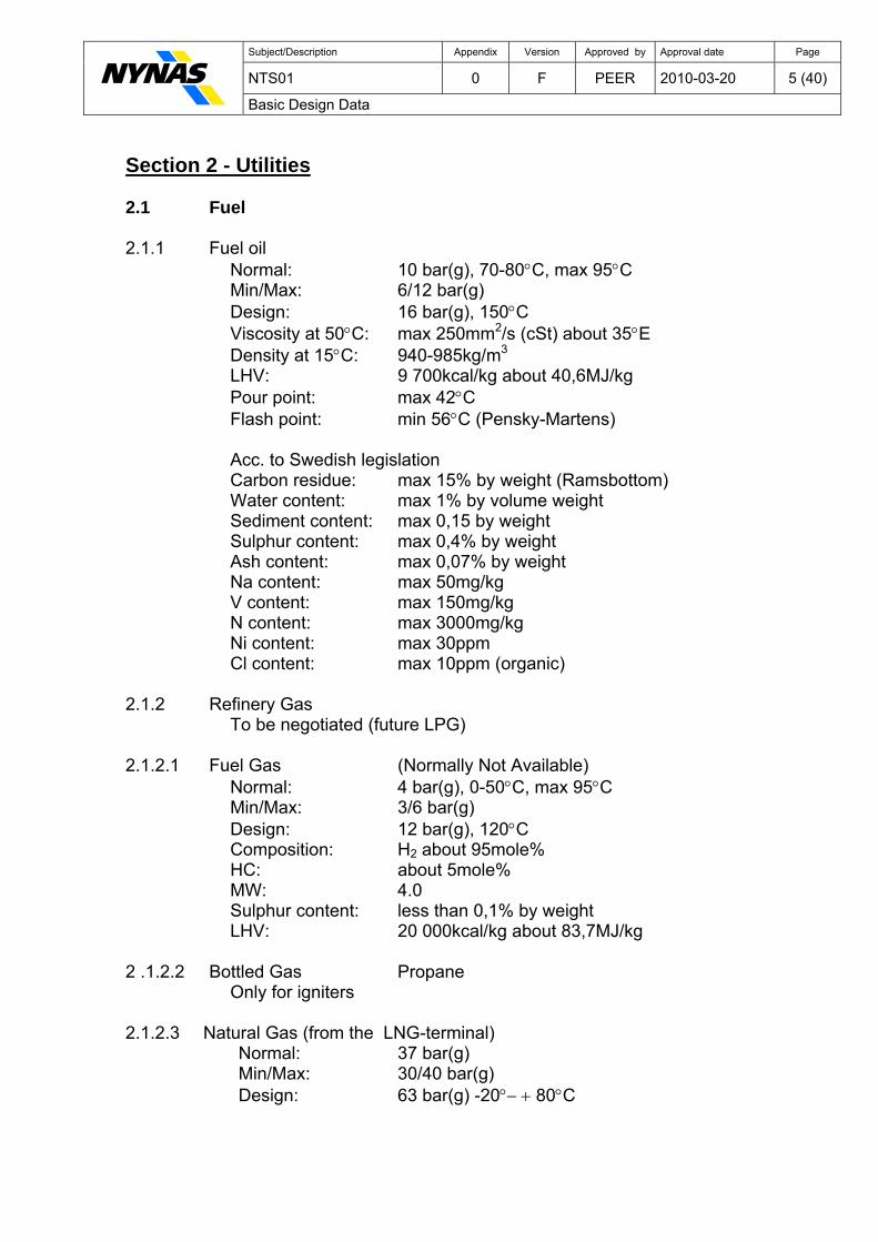
2.1.1 Fuel oil
Normal: 10 bar(g), 70-80°C, max 95°C Min/Max: 6/12 bar(g) Design: 16 bar(g), 150°C Viscosity at 50°C: max 250mm2/s (cSt) about 35°E Density at 15°C: 940-985kg/m3 LHV: 9 700kcal/kg about 40,6MJ/kg Pour point: max 42°C Flash point: min 56°C (Pensky-Martens) Acc. to Swedish legislation Carbon residue: max 15% by weight (Ramsbottom) Water content: max 1% by volume weight Sediment content: max 0,15 by weight Sulphur content: max 0,4% by weight Ash content: max 0,07% by weight Na content: max 50mg/kg V content: max 150mg/kg N content: max 3000mg/kg Ni content: max 30ppm Cl content: max 10ppm (organic)
2.1.2 Refinery Gas
To be negotiated (future LPG)
2.1.2.1 Fuel Gas (Normally Not Available) Normal: 4 bar(g), 0-50°C, max 95°C Min/Max: 3/6 bar(g) Design: 12 bar(g), 120°C Composition: H2 about 95mole% HC: about 5mole% MW: 4.0 Sulphur content: less than 0,1% by weight LHV: 20 000kcal/kg about 83,7MJ/kg
2 .1.2.2 Bottled Gas Propane
Only for igniters
2.1.2.3 Natural Gas (from the LNG-terminal) Normal: 37 bar(g) Min/Max: 30/40 bar(g)
Design: 63 bar(g) -20°− + 80°C
Subject/Description Appendix Version Approved by Approval date Page
NTS01 0 F PEER 2010-03-20 6 (40) Basic Design Data
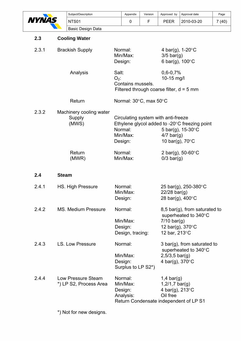
Composition: See analysis below LHV: 15,163 kWh/kg LNG Sm³: Means one (1) m³ at 1,013 bar(a) and +15°C 1 Sm³ vaporised LNG equals to 0,74 kg LNG
Component Unit Typical value Maximum value Minimum value N2 mol% 0,3115 2,0 CO2 mol% 0,0052 CH4 mol% 90,0707 C2H6 mol% 8,9773 C3H8 mol% 0,5813 iC4H10 mol% 0,0215 nC4H10 mol% 0,0268 iC5H12 mol% 0,0027 nC5H12 mol% 0,0027 S total ppmw 20 H2O vol% 0,00001 1,0 Pb ppbw 10,0 Hg microg/S
m³ 0,01
C3+ mol% 0,63 C5+ mol% 0,006 Unsaturated hydrocarbons mol% 0,00001 Cl/halogens ppmw 1,0 Gross Caloric value MJ/Sm³ 42,6 38,6 Higher Wobbe index MJ/Sm³ 53,4 51,0
2.2 Electric Power System Voltage 2.2.1 MV 21,5 kV +5%, 3 Phases, 50 Hz, IT * (constr.voltage 24kV) MV 10,5 kV +5%, 3 Phases, 50 Hz, IT * (constr.voltage 12kV)
2.2.2 LV 690 V +5%, 3 Phases, 50 Hz, TN** (TN-S) 525 V +5%, 3 Phases, 50 Hz, IT * (for old system) 230/400 V +5%, 3 Phases, 50 Hz, TN** (TN-S)
2.2.3 Emergency power 525 V + 0%, 3 Phases, 50 Hz, IT * (for old system)
Diesel Generator 230/400 V +5%, 3 Phases, 50 Hz, TN** (TN-S)
2.2.4 Uninterrupted Power Supply (UPS and DCP) MV + LV Sub-station: 110 VDC +20-10% + and - pole high impedance earthed 24 VDC +20%-10% + and - pole high impedance earthed
Instrumentation: 230 V +2%, 1 Phase 50 Hz + 1%, TN** (TN-S) 24 VDC +20-10% negative pole earthed TN**
* IT = High impedance earthed neutral ** TN = Power system solidly earthed TN-S = Separated PE and N
Subject/Description Appendix Version Approved by Approval date Page
NTS01 0 F PEER 2010-03-20 7 (40) Basic Design Data
2.3 Cooling Water
2.3.1 Brackish Supply Normal: 4 bar(g), 1-20°C Min/Max: 3/5 bar(g) Design: 6 bar(g), 100°C
Analysis Salt: 0,6-0,7%
O2: 10-15 mg/l Contains mussels.
Filtered through coarse filter, d = 5 mm
Return Normal: 30°C, max 50°C
2.3.2 Machinery cooling water Supply Circulating system with anti-freeze
(MWS) Ethylene glycol added to -20°C freezing point Normal: 5 bar(g), 15-30°C Min/Max: 4/7 bar(g) Design: 10 bar(g), 70°C
Return Normal: 2 bar(g), 50-60°C (MWR) Min/Max: 0/3 bar(g)
2.4 Steam
2.4.1 HS. High Pressure Normal: 25 bar(g), 250-380°C
Min/Max: 22/28 bar(g) Design: 28 bar(g), 400°C
2.4.2 MS. Medium Pressure Normal: 8,5 bar(g), from saturated to superheated to 340°C
Min/Max: 7/10 bar(g) Design: 12 bar(g), 370°C
Design, tracing: 12 bar, 213°C
2.4.3 LS. Low Pressure Normal: 3 bar(g), from saturated to superheated to 340°C
Min/Max: 2,5/3,5 bar(g) Design: 4 bar(g), 370°C Surplus to LP S2*)
2.4.4 Low Pressure Steam Normal: 1,4 bar(g)
*) LP S2, Process Area Min/Max: 1,2/1,7 bar(g) Design: 4 bar(g), 213°C Analysis: Oil free Return Condensate independent of LP S1
*) Not for new designs.
Subject/Description Appendix Version Approved by Approval date Page
NTS01 0 F PEER 2010-03-20 8 (40) Basic Design Data
2.4.5 Oil free condensate to be returned to Battery Limit. Condensate headers Design:
MS steam: 12 bar(g), 200°C LS steam: 4 bar(g), 200°C
2.5 Water
2.5.1 Raw Water Supply Source of Water: Älvikssjön (Lake)
Normal: 3 bar(g), 1-25°C Min/Max: 1/4 bar(g) Design: 6 bar(g), 50°C Analysis Average Min/Max Ph: 7,1 6,3 / 7,7
Conductivity, uS/cm: 265 197 / 418 SiO2, mg/l: 9,0 1,0 / 25,0 Oxygen consumed (KMnO4) mg/l: 29,3 21,0 / 43,0 Hardness, °dH: 5,0 2,5 / 8,0 Chloride, ppm: 20 -- / -- Iron, mg/l: 0,8 0,5 / 2,5
2.5.1.1 Demineralised Water (Softened Raw Water)
Normal: 6 bar(g), 20°C Min/Max: 5/8 bar(g) Design: 12 bar(g), 50°C Treatment: Sand filtering/Flocculation
Softening (Not tot. desalination)
Analysis Hardness, °dH: less than 0,012
2.5.1.2 Desalinated Water Normal: 6 bar(g), 20°C Min/Max: 5/8 bar(g) Design: 12 bar(g), 50°C Treatment: Sand filtering/Flocculation
Desalinated (Not tot. desalination)
Analysis Hardness, °dH: less than 0,010
2.5.2 BFW (Deaerated Demineralised Water) Normal: 40 bar(g), 105-118°C Min/Max: 35/45 bar(g) Design: 55 bar(g), 150°C Treatment: Deaeration
Subject/Description Appendix Version Approved by Approval date Page
NTS01 0 F PEER 2010-03-20 9 (40) Basic Design Data
Analysis Hardness, °dH: less than 0,012 pH: 9,2-9,6 Alkalinity NaOH mg/l: 12-25 Chloride mg/l: 15-20 Dissolved oxygen: less than 0,01
2.5.2.1 BFW (Deaereated Desalinated)
Normal: 40 bar(g), 105-118°C Min/Max: 35/45 bar(g) Design: 55 bar(g), 150°C Treatment: Deaeration
Analysis Hardness, °dH: less than 0,010
pH: 9,2-9,6 Alkalinity NaOH mg/l: < 0,05
Dissolved oxygen: less than 0,01
2.5.2.2 BFW For process area 1 only (Make Up Water Desalinated) Normal: 10 bar(g), 30-40°C Min/Max: 8/12 bar(g) Design: 15 bar(g), 70°C Treatment: Deaeration
Analysis Hardness, °dH: less than 0,010
pH: 9,2-9,6 Alkalinity NaOH mg/l: < 0,05
Dissolved oxygen: less than 0,01
2.5.3 Potable Normal: 4 bar(g), 4-20°C Design: 10 bar(g)
Potable Water is delivered from the Nynashamn Municipality.
2.6 Nitrogen Normal: 11 bar(g) ambient
Continuous duty max 120 Nm3/h Min/Max: 8/15 bar(g)
Design: 16 bar(g), 100°C Available, max: 1200 Nm3/h at 8 bar(g) 4800 Nm3/h / 24 h Tank net volume: 35 000 Nm3 as gas
Rupture disc to be provided upstream safety relief valves
2.7 Compressed Air Design: 12 bar(g) Analysis: Dry (-25°C at 6 bar(g)), oil free
Subject/Description Appendix Version Approved by Approval date Page
NTS01 0 F PEER 2010-03-20 10 (40) Basic Design Data
2.7.1 Instrument Air Normal: 5,5 bar(g), ambient
(Prioritised) Min/Max: 5/6 bar(g) Standby: Diesel-driven air compressors starting at 4,8 bar(g)
2.7.2 Plant Air Dry Normal: 6 bar(g), ambient
Min/Max: 5/7 bar(g)
2.8 Hydrogen Make up Normal: 19,5 bar(g) 20-40°C
Min/Max: 18/21 bar(g) 10-50°C Design: 24,5 bar(g) Available max: Supplied by Company
Analysis H2 min: 99,0 vol% CO+CO2 max: 10 vppm CH4 max: 1 vol%
2.9 Oxygen On request from Company. Section 3 - Codes, Standards And Requirements
3.1 General requirements
The latest editions of the codes and standards in this document, Sections 3 to12 will govern. Specific standards are shown under the equipment section. In case of conflict between Swedish Regulation and Nynas Technical Standards the more stringent shall govern. NTS01 has higher ranking than other Nynas Technical Standards. Deviations from given standards shall be listed for Company approval. Drawing F54400 ‘Raffinaderikarta’ (Refinery map) must only be upgraded by Company network AutoCAD software due to the Company specific coordinate system used.
Section 4 - Authority Codes, Standards And Requirements 4.1 General Codes and specifications for all types of equipment 4.1.1 European Directives: Atex 94/9/EC PED 97/23/EC Machinery 89/392/EEC EMC 89/336/EEC

Subject/Description Appendix Version Approved by Approval date Page
NTS01 0 F PEER 2010-03-20 11 (40) Basic Design Data
4.1.2 Swedish/European Directives: AFS 1993:10 Maskiner och vissa andra
tekniska anordningar (Swe). Directive 89/392/EEG (EGT No L 183,26.6.1989).
AFS 1995:5 Utrustningar i explosionsfarlig miljö. (Swe). Directive 94/9/EG (EGT No
L 100, 19.4.1994, page 1 Celex No 394L0009) and 83/189/EEG
(EGT No 26.4.1983, page 8 Celex No 383L0189). AFS 2005:16 Buller (Noise).(Swe). Directive 2003/10/EG (EUT No L42,15.2.2003, Celex No 32003
L0010). SS 031711 Warning signals with sound and light. AFS 2000:42 Lighting. Arbetsplatsens utformning, belysning (Swe).
Directive 89/654/EEG 30 Now. 1989 (EGT No L393,30.12.1989, Celex 389L0654).
4.2 General Codes for Electrical (and Instrumentation) 4.2.1 Installation and Maint. ELSÄK-FS 1999:5 Swedish Electrical Regulation with (Starkströmsföreskr. updates ELSÄK-FS 2006:3 “Blå boken”) Design and Erections ELSÄK-FS 2004:1 Swedish Electrical Regulation with of El. Installations updates ELSÄK-FS 2006:2 (Starkströmsföreskr.) SS 436 40 00 “Elinstallationsreglerna” (HD384-seroes) Electrical Installations 4.2.2 Safe Work: ELSÄK-FS 2006:1 Swedish Electrical Regulations EN 50110-1 Operation of Electrical Inst. 4.2.3 EMC ELSÄK-FS 2003:1 Electro Magnetic Compatibility 4.2.4 Authorization: ELSÄK-FS 2007:2 Swedish Electrical Regulations
4.2.5 Hazardous areas: ELSÄK-FS 1995:6 Swedish Electrical Regulations with Electr. Equipm. in updates ELSÄK-FS 2006:4 Hazardous Area EN 60079-10 Classification SEK Handbook 426 Swedish Guidance Notes
Subject/Description Appendix Version Approved by Approval date Page
NTS01 0 F PEER 2010-03-20 12 (40) Basic Design Data
(For details, ANSI/API RP505 Recommended practice for if needed) classification HC areas Normally Zone IIA T3
Hydrogen areas Normally Zone IIC T3 4.2.6 Symbols EL EN 1346 Codes and classes (marking) IEC 60617 Graphical symbols EN 61082 General drawing rules SEK Handbook 493 Swedish Guidance Notes 4.2.7 Buildings: SS-421 01 01 Power installations exceeding
(HD63751) 1 kV AC (Swe) SEK Handbook 438
436 21 01 Electrical operating area for low-voltage switchgear and control
gear (Swe)
4.2.8 Switchgear EN 60298 A.C. metal-enclosed switch- and control gear for rated voltages
above 1 kV to 52 kV. EN 60947-1 Low-voltage switchgear and control
gear (1 kV and lower). 4.2.8.1 Earthing: SS 436 21 10 Installations for grounding switchgear
above 1 kV. 4.2.8.2 Apparatus: EN 61346 Classification and codes 4.2.9 Transformers: EN 60076 Power transformers. 4.2.9.1 Distribution: SS 427 02 01 Three-phase oil-immersed
transformers 50 Hz, from 50 to 2 500 kVA
4.2.10 Motors, EN 60034 Rotating electrical machines Diesel Generators: (part 22 generators) 4.2.11 Power Cables: SS 424 14 16 7/12 kV to 21/36 kV SS 424 14 18 0,6/1 kV SS 424 02 19 House wiring 300/500 V 4.2.12 Control Cables: SS 424 03 21 300 / 500 V SS 424 03 23 150/250 V 4.2.13 Telecom. Cables: SS 4241222 Above ground SS 4241642 Indoors SS 4241651 Indoors and outdoors 4.2.14 Earthing Cables: SS 4240231 Above and below grade. SEN 240103 Below grade
Subject/Description Appendix Version Approved by Approval date Page
NTS01 0 F PEER 2010-03-20 13 (40) Basic Design Data
4.2.15 Enclosure: EN 60529 Degrees of protection provided by enclosures (IP Code)(Swe) 4.2.15.1 Cable Entry: EN 50262 Cable glands for electrical (A1 and A2) installations. 4.2.16 UPS: EN 62040 Uninterruptible power systems 4.2.17 Lighting: EN 12464-1 Indoors only EN 50171 Emergency escape lighting EN 1838 Emergency lighting 4.3 General Codes for Instrumentation The same codes as for electrical and pressurised equipment are also applicable
for instrumentation with exceptions below. 4.3.1 Symbols: ANSI/ISA-S5.1 Instrumentation symbols and Identification. 4.3.2 Thermocouples: EN 60584 References and tolerances. 4.3.3 RTD: EN 60751 Platinum 3-wire system. 4.3.4 Orifices: ISO 5167 Preferred square edge concentric
plates. 4.3.5 Control Valves: ISA S75.01 Sizing. 4.4 General Codes for Pressurised Equipment
4.4.1 Swedish codes: AFS 1999:4 Tryckbärande anordningar
(PED 97/23/EC)
AFS 2005:2 Tillverkning av vissa behållare, rörledningar och anläggningar.
(Dir 98/34) AFS 2005:3 Besiktning av trycksatta anordningar AFS 2002:01 Användning av trycksatta anordningar
Swedish/European Codes: SÄIFS 2000:2 Hantering av brandfarliga vätskor Directive 98/34EG June 22 1998; 98/48/EG July 20 1998; 1999/45/EG May 31 1999; (EGT No L2000,
30.7.1999; Celex 399L0200).
Subject/Description Appendix Version Approved by Approval date Page
NTS01 0 F PEER 2010-03-20 14 (40) Basic Design Data
SÄIFS 2000:4 Rörledningar för brandfarliga gaser. Directive EGT L204,21.7.1998 Page 37, Celex 398L0034; EGT 217,
5.8. 1998 Page 18, Celex 398L0048. Material Accredited Inspection acceptance Company in Sweden Other Codes: ANSI Pipe and equipment nozzle sizes
ASME Sec. VIII Div. 1. Pressure vessels ASTM A-450 Electric Resistance Welded
carbon and stainless steel tubes. EN 287 Welding Qualification EN ISO 15607-14 Qualification of Welding Procedures EN 13445 Unfired Pressure Vessels EN 13480 Metallic industrial piping
4.4.2 Basis for operation/maintenance and Risk analyses, PED 97/23 EC:
A risk analyses shall be performed by the Manufacturer and/or by Company.
Design Pressure Min/Max: As specified 1) Operation Pressure: As specified 1) Design Temperature: Min. when pressurised 1) Design Temperature: Max. as specified 1) Operation Temperature: As specified 1) Number of full pressure cycles: Estimated by Company 2) - temperature and of service cycles: Estimated by Company 2) Ambient condition: NTS01 Intervals between inspection: 48 Months Expected life time: 25 Years Remaining lifetime will be reconsidered after every inspection. Company responsibility. Base Material: As specified 1) Corrosion allowance: As specified 1)
1) As specified on Dwg or Data Sheet 2) Fatigue calculations has to be performed acc. to EN 13445 when the number of cycles is over 500.
The risk analyzes shall contain as a minimum the following items: • Description of Pressure Vessel function in the Process. • Description of safety system for pressure and temperature. • Description of the record of pressure and temperature cycles. • Description of inspection methods during operation and shut down • External forces from wind, temperature shall be defined • Allowable loads on nozzles shall be defined.
Subject/Description Appendix Version Approved by Approval date Page
NTS01 0 F PEER 2010-03-20 15 (40) Basic Design Data
Section 5 - Equipment Codes, Standards And Requirements
5.1 Design – general 5.1.1 Material (SS): Naphthenic acid corrosion protection from 200 0C
and upwards will be subjected to Company approval. 5.1.2 Stud bolts and nuts: Process equipment and piping shall have
UNC threads up to and including 1” and for all others UN threads. Material shall be suitable for use at the
temperature in question but at least ASTM A193 B7/A 194 2H and marked with material grade and acc. to
ASME B16.4 and B18.2. Bolts and nuts for steel structures shall be metric and hot galvanised and shall comply with EN 1990-1999.
DIN acc to NTS38, Appendix 4. 5.1.3 Design pressure: For equipment maximum operating plus 10% but
never less than 2 bar above maximum operating pressure. In any case a minimum design pressure of 2,8 bar(g) is required.
5.1.4 Design temperature: For equipment maximum operating plus 30°C.
Exception: Parts exposed to direct flame, hot flue gases or direct electrical heating, see API Recommended Practice 530.
5.1.5 Welding: All root beads in butt welds shall be TIG welded regardless of material quality.
5.1.6 PMI See the Document Positive Material Identification (PMI)
Path to NMS: NyPort/Tools & Services/Handbooks/ NMS Nynas Management System/Handbooks and Doc ID 002019. 5.2 Gaskets 5.2.1 Standards: NTS16
ASME/ANSI B16.20 spiral wound and ring joints
5.2.2 Expanded graphite: >98% pure, <50 ppm Cl, <300 ppm F, <1000 ppm S
5.2.3 Asbestos: Not allowed
5.3 Exchangers, Shell and Tube 5.3.1 Design Code: TEMA Class R with Shell G, H, J, K and E.
Subject/Description Appendix Version Approved by Approval date Page
NTS01 0 F PEER 2010-03-20 16 (40) Basic Design Data
5.3.2 Design conditions: The same pressure on both sides. - temperature: Internal parts, for the greatest temperature. - LMTD Greater than 0,8.
- velocity: Transitional flow not acceptable. - vibration: Flow induced, to be avoided. 5.3.3 Type: Floating Head, removable channel cover.
- HP and Hydrogen: U-tube type, bonnet (integral cover). - fixed tube sheet: Only by Company approval. - two shell pass: Not allowed. - Joint construction: Unconfined plain face not allowed
5.3.4 Other type: Kettle - weir: Welded tightly directly after the bundle with 2 “ of process fluid above top of tubes. - riding rails Fully welded to shell to support the bundle.
- BFW inlet nozzle: Located to avoid ‘by-passing’ to blow down valve.
5.3.5 Tube bundles: When removable, sliding strips or bars required.
- baffles: Segmental or double segmental, vertical cuts and V-notch for draining. Kettle type, full diameter tube support. - weight: Preferred max 8 tonnes.
5.3.6 Tube sheet: Tube holes for S.S, special close fit (TEMA alt.).
- tube projection 3 mm ±1,5 mm beyond tube sheet surface.
5.3.7 Tubes: Non-ferrous and low alloy seamless
- preferred size: Length (16 feet) 4877 mm, O.D. 3/4" 19,05 mm. Carbon, Low alloy, BWG 14. Non ferrous, high alloy, BWG 16. - preferred pitch: 1", Rotated Square (45�). - finned: Not allowed. - U-bends: Oriented vertically, min. radius 1,5 times O.D.
5.3.8 Channel partition: Orientation protection against the tube sheet. ‘Half-moons’, 18 x 4 mm.
5.3.9 Water cooled: To be agreed with Company - Tube bundle: SS depending on service (254SMO) - Channels: Carbon steel depending on service - Cover: SS depending on service (SAF2205)
- Water velocity: 1 to 2,5 m/sec (for Al-brass)
Subject/Description Appendix Version Approved by Approval date Page
NTS01 0 F PEER 2010-03-20 17 (40) Basic Design Data
5.3.10 Stacked exchangers: Two counter-saddles on lower exchanger. The Shell nozzles as close to the Channel nozzles as possible. The saddle nearest the Shell/Channel connections tightly bolted while the other of sliding type. Saddles to be fully welded to the shell for removable bundles. Shop pre-assembled after tests.
- saddles: Bolts and shim plates to be included.
5.4 Exchangers, Air Cooled
5.4.1 Design code: API 661/ ISO 13706 5.4.2 Width: max 3100 mm 5.4.3 Slip on flanges: Not allowed.
5.4.4 Preferred tube size: Carbon, low alloy steel, O.D. 25 mm (BWG 12). High-alloy, duplex steel, O.D. 25 mm (BWG 14).
Length 4877, max 9144 mm. Width max 3100 mm. 5.4.5 Finned tubes: Embedded or Integral. 5.4.6 Tube sheet joints: Un-finned length 50 mm from tube sheet surface 5.4.7 Cover plates: Flanged construction with confined gaskets. 5.4.8 Auto variable fan: Loss of control, maximum cooling 5.4.9 Balanced fan: Static and dynamic
5.4.10 Tube bundles: Combined in one bay for different services shall be provided with louvers for each service.
Cooling capacity adjustable independently for each bundle.
5.5 Exchangers, Plate 5.5.1 Design code: API 662 / ISO 15547
Design to be agreed with Company. 5.6 Fired Heaters 5.6.1 Design code: Tube thickness: API 530 / ISO 13704 - General: Manufacturer standard to be approved by Company. - Safety system: NFPA 86 and Swedish Hotoil code.
Subject/Description Appendix Version Approved by Approval date Page
NTS01 0 F PEER 2010-03-20 18 (40) Basic Design Data
5.6.2 Design conditions: Low NOx burners required - operation: heat absorption, 125% of normal design - vol. heat release: Oil firing: 565 MJ/m3. Gas firing: 670 MJ/m3. - pressure drop: For process side based on fouled tubes. - turn down: At least 4 to 1. 5.6.3 Burners: Low NOx in corporation with Company - emission: Target for gas firing: ≤20mg/MJ. Target for fuel oil firing :(2.1.1): ≤80mg/MJ. - igniters: High Energy Ignition Lance (no pilots) - guns: Removable while heater is in operation 5.6.4 Platforms: For any equipment requiring service, inspection or
operator attention. - stairs Minimum at burner level and inspection levels. 5.6.5 Insulation: Preferred lining ceramic fibre. - shell temperature: Maximum 70 0C based on 30 0C still air. 5.6.6 Clearance: At hearth firing minimum 2100mm, without 1500 mm. -with header boxes: Tubes to be min 150 mm into the box. 5.6.7 Snuffing steam: Rate at 10 bar(g), half the design volumetric air rate. - header boxes: When plug type, 2 “ connections required. 5.6.8 Ductwork: When common flue gas system, isolation means to be
provided 5.6.9 Fans: Non-sparking type. Rated air flow 125% at design load.
Static head 145%. Without surge in load range. - rotating element: Statically and dynamically balanced. - couplings: Metal type. Non-sparking guard. 5.7 Pressure Vessels 5.7.1 Standard: See NTS 25.
5.7.2 Design code: See general codes.
5.7.3 Manholes: Outside diameter min. 508mm (20") and min. 450mm I.D. (Note 1)
For work in flammable and inert atmosphere min. ID 600mm. Covers equipped with hangers or davits.
Note 1: For Steam-boilers min 300*400mm, as per Swedish Boiler Code. 5.7.4 Shell and Heads: Corrosion allowance minimum 1 mm. Thickness minimum 3 mm for stainless steel and 4 mm for all other materials or 2,5 mm plus calculated.
Subject/Description Appendix Version Approved by Approval date Page
NTS01 0 F PEER 2010-03-20 19 (40) Basic Design Data
5.7.5 Flanged heads: To be supplied with lifting lugs and break flanges outside head flange radius for easy removal.
5.7.6 Internal cladding: Thickness min 3 mm. Strip lining or intermittent bonding
only after Company approval. Cracks greater than 1,5 mm removed and repaired.
5.7.7 Nozzles: Designed for a load of 200 kg at flange connection.
5.7.8 Flanges: Slip-on flanges not allowed. Permit the use of standard gasket sizes
5.7.9 Supports: Saddles to be provided with intermediate plates welded to the shell. Concrete saddles to be provided with corrosion plates between the saddle and the vessel. Skirts designed to withstand the vessel design temperature Skirts to have minimum 500 mm ID, ventilated and ring enforced.
5.7.10 Internals: Trays: Equalised load of 1000N/m2 or weight of water 50 mm above highest weir setting. Downcomers: 3000 N/m2 or head of water one- half of the downcomer.
Pans: 7000 N/m2 or weight of water at maximum height of the pan.
Trays and support members: Live load of 150 kg At any point of installed assembly. Tray sections shall pass through the manholes.
5.8 Piping and Valves 5.8.1 Standard: See NTS38. 5.8.2 Design code: API 600 Bolted Bonnet Steel Gate Valves API 602 Compact Steel Gate Valves ISO 5208 Pressure testing of valves NTS38 Piping General with appendices 1 to 5. 5.8.3 Piping: Revamp tie-ins and Offsite may be DIN. 5.8.3.1 Certificate: All pipes, flanges, fittings and valves must be supplied
with mill certificate acc. to EN 10204-3.1 (or equivalent). Heat number shown on the certificate shall be marked
on each piece by mill.
5.8.3.2 Components: Shall be in acc. with the ANSI/ASME standards. Stub in connections in accordance with ANSI.
Subject/Description Appendix Version Approved by Approval date Page
NTS01 0 F PEER 2010-03-20 20 (40) Basic Design Data
5.8.3.3 Material: Normally in accordance with ASTM designation but with the requirements for the specified material in the PMA. (Particular Material Appraisal).
5.8.3.4 Thickness: In acc. with EN 13480.
5.8.3.5 Fittings: For use of fittings refer to the standards selection chart
NTS38, Appendix 2. 5.8.3.6 Compression fittings: Not allowed for piping carrying process fluids other
than for instrument lines.
5.8.3.7 Nipples: Between the line equipment and the first isolating valve should be from schedule 160 pipe minimum
5.8.3.8 Schedules: For major projects pipe schedules are accepted to be
calculated, line by line. The schedules given in NTS38, Appendix 2 is still valid for pipes 2” and smaller.
5.8.3.9 Magnetic particle: A supplementary magnetic test as per ASTM A234-S4,
ASTM A182-S4, ASTM A403-S7, liquid penetrant test is requested for stainless steel. Shall be carried out on all fittings. Acceptance level shall be per ASME VIII Div. 1 App. 6.
5.8.4 Valves all types, All instruments and sample points mounted on lines/ 1500 lbs or higher: vessels to be provided with double block valves. Drains and vents provided with one valve and a blind flange. 5.8.5 Valves hot oil: Primary seals of metal bellows required 5.8.6 All valves: Shall be numbered acc. to NTS14. 5.9 Pumps, all types 5.9.1 Design code: Relevant API / ISO. To be agreed with Company. - Tracing: NTS36 When heat conservation is needed for pump installation the use of tracing or jacketing shall be considered and agreed with Company. 5.9.2 Design conditions: Minimize the types thus limiting the number of spares
- Overcapacity: Centrifugal, 20 % Reciprocating and others 10%
- warm-up lines: a. when pump temperature is above 235 0C
Subject/Description Appendix Version Approved by Approval date Page
NTS01 0 F PEER 2010-03-20 21 (40) Basic Design Data
b. when ambient temperature is at or below process flow pour point.
c. when b at intermittent flow 5.9.3 Pump types: Single, multistage, horizontal, and vertical.
In-line to be approved by company - axially split: Not allowed at liquid density below 700 kg/m3
5.9.4 Drivers: Electric motors - rated over 500 kW: To be agreed with Company. 5.9.5 Material: Cast or Ductile Iron and Bronze not allowed. 5.9.6 Couplings: Non-sparking, spacer type and cover 5.9.7 Mechanical Seals: API 682. Cartridge Seal Double mechanical seals shall be used for fluids pumped at temperatures exceeding the flashpoint
5.9.8 HC-Emission See Section 11.
5.9.9 Horizontal clearance: Normally 3 m. No pumps for combustibles to be located under main pipe racks.
5.10 Pumps, Centrifugal 5.10.1 Design code: API 610 / ISO 13709 Heavy duty pumps
API 682 / ISO 21049 Sealing system API 685 / Seal less centrifugal pumps ISO 5199, ISO 2858 Medium duty pumps
5.10.2 Suction specific speed: Maximum 210 in SI units (API 610-Apendix A:2)
5.10.3 Shut off head: 110 to 120 % of head at design flow
5.10.4 NPSH: Greater than 0,3 m of available – required
5.10.5 Mechanical Seals: API 682 Cartridge Seal
5.10.6 Heavy duty: Rated discharge pressure greater than 20 bar(g)
Operating temperature less than -20°C Operating temperature greater than 150°C Operating speed greater than 3000 rpm Capacity > 100 m3/h
5.10.7 Medium duty: All others (except heavy duty) but maximum two-stage allowed
Subject/Description Appendix Version Approved by Approval date Page
NTS01 0 F PEER 2010-03-20 22 (40) Basic Design Data
5.11 Pumps, Screw 5.11.1 Screw pumps: Internal pressure relief valve required External pressure control also required
5.12 Compressors, Reciprocating 5.12.1 Design code: API 618, API611, API671, API613 5.12.2 Overcapacity: 10% 5.12.3 Piston speed: Average 3 m/sec non-lubricated Average 5,5 m/sec lubricated 5.12.4 Material: Cast iron not permitted for pressure containing cylinder
parts 11-13 chrome-hardened steel for piston rods 5.12.5 Crosshead: Connection to piston rod, hydraulic tightening nuts 5.12.6 Cylinders: Horizontal and fitted with liners 5.12.7 Distance pieces: Minimizing process gas leakage 5.12.8 Piston rod packing: To be approved by Company 5.12.9 Capacity control: Remote operated 5.12.10 Control systems: Minimum suction valve un-loaders for start-up 5.12.11 Instrument panel: For each compression unit 5.12.12 Valve temperatures: To be supplied 5.12.13 Detectors: Vibration, one-event- revolution, rod-drop 5.12.14 Other instrumentation: Minimum required acc. to API618 appendix G 5.12.15 Type of Drivers: Spares may be turbine driven.
5.12.16 Gear service factor: Minimum 2.75
5.12.17 Supply to include: Torsional analyses, Selection and sizes of transmission components Analog or digital study, Unit layout 5.12.18 Horizontal clearance: Normally 3 m. No compressors for combustibles to be
located under main pipe racks.
Subject/Description Appendix Version Approved by Approval date Page
NTS01 0 F PEER 2010-03-20 23 (40) Basic Design Data
5.12.19 Frame lubrication: Twin oil filters/coolers to be provided when the compressor is not spared.
5.13 Safety Relief Valves 5.13.1 Design codes: Relief Valve Code: API 520 & 521
5.13.2 Discharge: Relief Valves for steam, air, nitrogen and water may discharge to atmosphere. 5.13.3 Installation: Dual Interlocked safety relief valves if not otherwise stated.
5.13.4 Testing: Will be done during operation. Pressure connection required.
5.13.5 Bypass valves: In general provide double block valves with 3/4" bleed, to allow manual depressurising of equipment to
flare. Size of valves should be either 2" or inlet size of relief valve, whichever is smaller.
5.13.6 Approval: Shall be obtained for all safety relief installations from a Swedish Accredited Inspection Company.
5.14 Electrical 5.14.1 Standard: NTS 18 5.14.2 Installation: Cable racks shall not be installed above or below
equipment where leakage may occur and a fire may cause damage to the cables.
5.14.3 Safety switches Only for equipment in Non Hazardous Area only. 5.14.4 Distribution System: All equipment belonging to the same unit
irrespective of location, shall be fed from the same switchgear. To be agreed with Company.
5.14.4.1 Medium Voltage
22kV Internal distribution system with/and transformers to lower voltage. 10kV High voltage motors (motors >630kW). 5.14.4.2 Low Voltage 690V Motors, UPS systems, Capacitor Banks 525V (exist. system) Motors, UPS systems, Capacitor Banks
Emergency power (DG) Selected motors, tracing and lighting, UPS 230/400V Electric tracing, lighting, outlets, heaters 110V DC Substation protection relays and switchgear control 24V DC Solenoids, instrumentation and other users.
Subject/Description Appendix Version Approved by Approval date Page
NTS01 0 F PEER 2010-03-20 24 (40) Basic Design Data
5.14.5 Motors above 300 kW: To be considered individually by connection to 10kV or 690V(525V) system after Company approval.
5.14.6 Transformers: Oil immersed 5.14.6.1 Ratings: 21,5 / 0,690 kV 500,1000,1500, 2000, 3150 kVA 21,5 / 0,400 kV 500, 1000 kVA 525 / 400 V 125, 300 kVA 5.14.7 LV connection Bus bar Over 300 kVA Cable 300 kVA and below 5.14.8 Diesel generator: Overcapacity: 10% 5.15 Instruments 5.15.1 Standard: NTS39 5.15.2 All circuits: Shall be of intrinsically safe type. 5.15.3 Installation: All field instruments to be connected to Company Distributed Control System.
Cable racks shall not be installed above or below equipment where leakage may occur and a fire may
cause damage to the cables.
5.15.4 Loop accuracy: Depends on application. In general best available technology shall be used for equipment affecting
process yield, mass balance and equipment used for accounting purposes. 5.15.5 Tank radar accuracy: Better than ±1mm, for the range 0-40m.
5.15.6 Transmitters: All transmitters shall have HART or FF communication and be connected to AMS.
Suitable device description, compatible with Nynas existing AMS revision, shall be provided for
transmitters.
5.15.7 Control Valves: Smart positioners with advanced diagnostics, using HART or FF communication and connected to AMS, shall be used. For valves affecting capacity or valves that may be difficult to bypass process diagnostics shall be used.
Size: Flanged 1” and above.
Block and by-pass valves for all control valves that can not be taken out of service without stopping the unit.
Subject/Description Appendix Version Approved by Approval date Page
NTS01 0 F PEER 2010-03-20 25 (40) Basic Design Data
5.15.8 Distribution System: All equipment belonging to the same unit number, irrespective of location, shall be fed from the
same Interface room. To be agreed with Company.
5.15.9 Heater interlocks: In principal according to requirements set forth in NFPA 86. 5.15.10 Process Safety and For all interlocks that shut down the entire unit or lead Heater interlocks: to loss of production 2 out of 3 voting in order to avoid trips in case of single instrument failure.
5.15.11 Instrument earth: Connected to electrical earth at one point only. 5.15.12 MOS Maintenance override switch shall be considered for trip signals and for equipment with short MTBF. 5.15.13 Switches and relays: Shall generally be of 24VDC “Fail safe” type with gold-plated contacts. Section 6 – Civil Works
6.1 Civil - general 6.1.1 Design Code: Building Regulations BBR, construction Design Regulations BKR, loading, piling Design Regulations BSK, welding steel structure Swedish Concrete Code BBK (Swe) Swedish Regulations for Steel Structures, BSK
Precast piles EN 12794:2005 Statliga Cementbestämmelser B1-1982, see BKR 6:611 Basic inspection
(http://www.boverket.se goto English, Downloads) (Euronorm).
6.1.2 Refinery Clearances: Clear headroom at grade not less than 2150 mm for equipment groups or over elevated platforms. See also section platforms.
6.1.2.1 Main roads: Min Widths, 6 m
Min Clearance 5 m but 7 m when handling heavy equipment. 6.1.2.2 Other roads and Min Widths, 4 m but 6 m when handling
pumps access ways: tube bundles and other heavy equipment. Min Clearance 4,5 m
Subject/Description Appendix Version Approved by Approval date Page
NTS01 0 F PEER 2010-03-20 26 (40) Basic Design Data
6.1.2.3 Fired Heaters and Min Clearance 15 m to pumps and vessels Stacks:
6.1.3 Type of Surface: Operation Areas Concrete in possible oil spillage areas and gravel elsewhere
Roads Asphalt paving Access ways Gravel
6.1.3.1 Surface falls: See also refinery sewer systems, run off coeff. All falls, max 150 mm and min 1:100, shall be arrowed on drawings. Drains to catch basins set 25 mm below paving.
6.1.4 Bunds around units: Shall be able to hold total amount of oil in the unit, but shall not be higher than pump plinths (300 mm).
6.1.4.1 Concrete curbs: 75 x 75 mm where necessary around specific equipment and equipment drain points. 6.1.5 Davits and trolley Typically, where mobile equipment is not planned, beams: and parts weighing over 45 kg and are subjected to
cleaning and repairs:
- Channels, covers and tube bundles of elevated tubular equipment
- Hydraulically operated slide valves - Motor operated valves - Tower relief valves - Compressor parts - Cooling tower screens.
6.1.6 Hoists: Recommended by Contractor or Company. 6.2 Foundations 6.2.1 Design Code: See previous Section 6.1.1.
6.3 Structures and supports
6.3.1 Design Code: See previous Section 6.1.1.
Protective coating see the section in this standard. Fire proofing see the section in this standard.
Subject/Description Appendix Version Approved by Approval date Page
NTS01 0 F PEER 2010-03-20 27 (40) Basic Design Data
6.4 Platforms, Stairs, ladders, walk-ways and handrails 6.4.1 Design Code: See previous Section 6.1.1.
6.4.2 Equipment standard: All stair treads, platform and walkway flooring shall be open type grating: - 25mm deep minimum - hole opening maximum 30 x 42mm with toothed
surface to prevent skidding - galvanised, with galvanised fasteners.
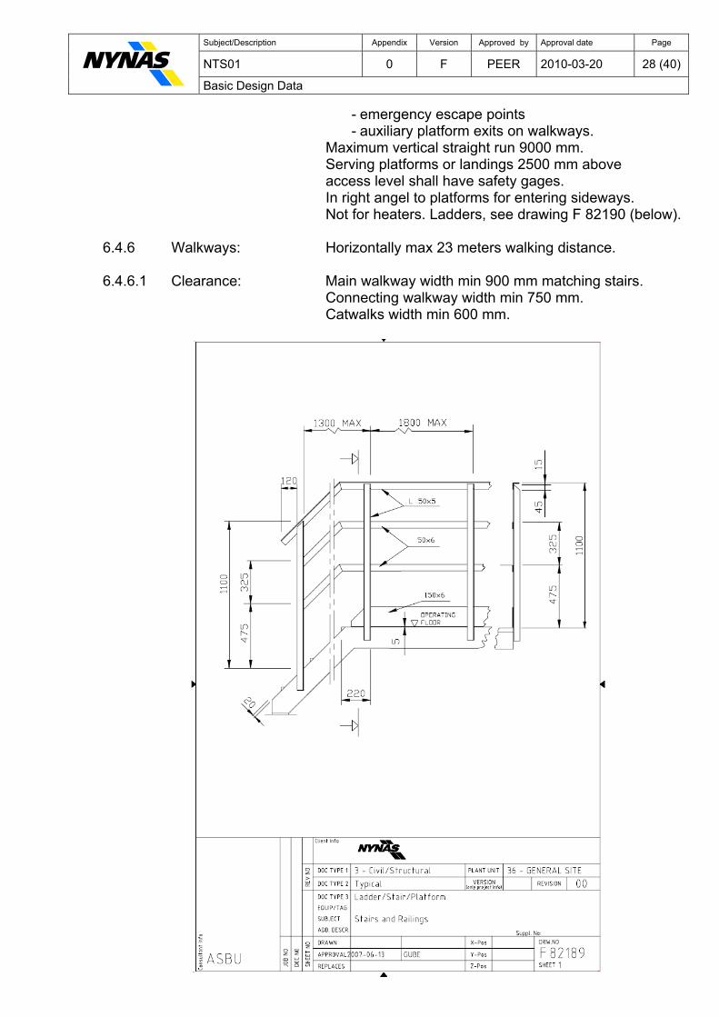
6.4.3 Platforms: Shall be provided at valves, manholes, safety valves and other equipment above ground requiring
regular operational attention, maintenance or inspection and at Heat Exchangers 2700 mm above grade for servicing of channel and shell cover ends. Self-closing gates for all exits to vertical ladders. Railings, see drawing F 82189 (below).
6.4.3.1 Clearance: Servicing manholes on vertical vessels. Min 300 mm below lower edge of manhole flange. Min 900 mm in front of the manhole flange. Min 300 mm on all sides from the edge of the flange. Servicing elevated channels and shells cover ends of
horizontal heat exchangers. Min 1200 mm in front of the cover ends. Min 300 mm on all sides from the edge of the flange. Servicing vertical tubular units. Min 900 mm from edge of the flange Min 1200 mm above platforms on channel and shell
cover flanges. Max 1800 mm.
6.4.4 Stairways: For heaters and equipment requiring regular operational attention. Vertical rise max. 5500 mm except for spiral Stairways. Minimum three risers, between 350 mm and 530 mm only one intermediate tread. Slope with 230 mm tread, 190 mm to 200 mm. Stairs, see drawing F 82189 (below). 6.4.4.1 Width: Min 900 mm back-to-back of stringers 6.4.5 Ladders: For - equipment and inspection openings - valves, instruments and platforms NOT requiring frequent attention
Subject/Description Appendix Version Approved by Approval date Page
NTS01 0 F PEER 2010-03-20 28 (40) Basic Design Data
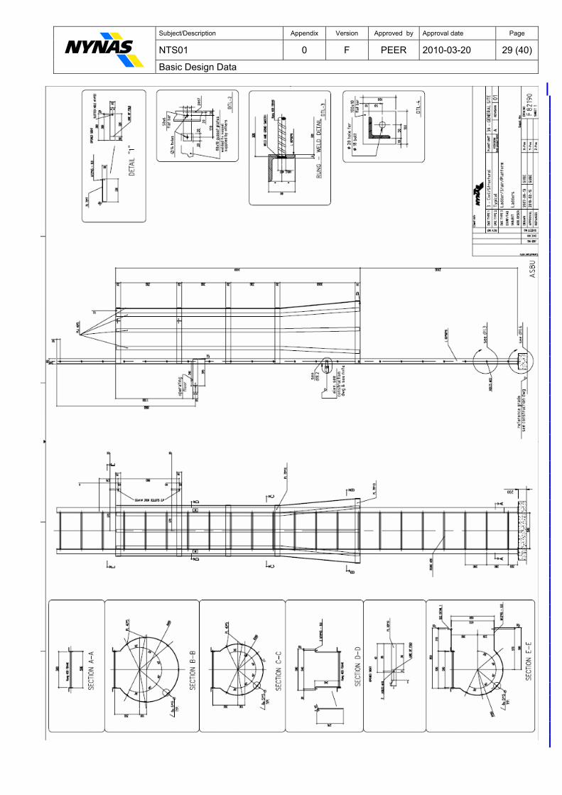
- emergency escape points - auxiliary platform exits on walkways.
Maximum vertical straight run 9000 mm. Serving platforms or landings 2500 mm above access level shall have safety gages. In right angel to platforms for entering sideways. Not for heaters. Ladders, see drawing F 82190 (below). 6.4.6 Walkways: Horizontally max 23 meters walking distance. 6.4.6.1 Clearance: Main walkway width min 900 mm matching stairs. Connecting walkway width min 750 mm. Catwalks width min 600 mm.
Subject/Description Appendix Version Approved by Approval date Page
NTS01 0 F PEER 2010-03-20 29 (40) Basic Design Data
Subject/Description Appendix Version Approved by Approval date Page
NTS01 0 F PEER 2010-03-20 30 (40) Basic Design Data
6.5 Buildings 6.5.1 Design Code: See previous Section 6.1.1.
6.5.2 El-Substation and Details see NTS18 Switchgear rooms. interface room: The whole building shall be of concrete. Internal partition reinforced concrete. Interface rooms to be reinforced and insulated. 6.5.2.1 Cable room floor: Steel structure with removable plates with antistatic top material. Height 0,8 m and 0,6 m below the ground level. 6.5.2.2 Main doors: Two, suitable to allow main switchboards to come in and out, and provided with anti panic handles. To be approved by Company. 6.5.3 Transformer room: Paving reinforced concrete with embedded service rails and oil catch pit filled with gravel. 6.6 Refinery Sewer Systems 6.6.1 Sewers, Drains: CWR Cooling Water Return, oil-free (Oily CWR not allowed)
PD Process water and surface drain (including storm water, draining of firewater) PDS Process Drainage System (oily) Collection in U/G pit with overflow and high alarms and pumped to battery limit.
CD Chemical Sewer (if required) Pressurised system A/G up to battery limit.
6.6.2 Materials: CWR, PD and PDS
ductile iron , stainless steel, reinforced con- crete or PVC acc. to actual circumstances.
CD epoxi coated concrete pipe, GRP pipes according to actual chemicals.
6.6.3 Design flow: PD Highest sum of process water, storm water
or process water, fire protection water. CWR, PDS and CD To be calculated acc. to process design.
- gravity sewers: ALL 2,0 m/s at max. design flow with wet section 70% of pipe ID.
0,7 m/s at min design flow with wet section 30% of pipe ID. 6.6.3.1 Storm water (cumulatively): Flow, section 1.3 rainfall - surface run off coefficient Roof, asphalt, concrete, hard soil 1,0 Ballasted, excluding tank basins 0,8 Sandy soil 0,2
Subject/Description Appendix Version Approved by Approval date Page
NTS01 0 F PEER 2010-03-20 31 (40) Basic Design Data
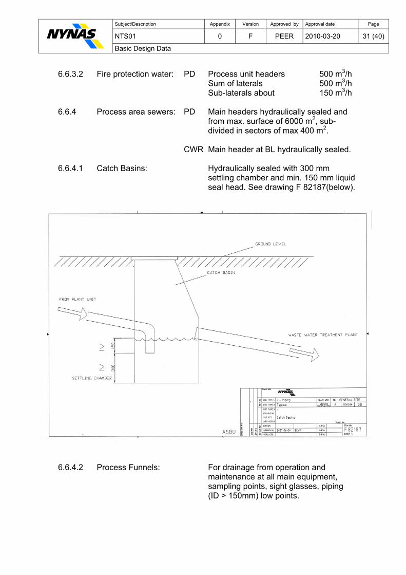
6.6.3.2 Fire protection water: PD Process unit headers 500 m3/h Sum of laterals 500 m3/h Sub-laterals about 150 m3/h 6.6.4 Process area sewers: PD Main headers hydraulically sealed and from max. surface of 6000 m2, sub- divided in sectors of max 400 m2. CWR Main header at BL hydraulically sealed. 6.6.4.1 Catch Basins: Hydraulically sealed with 300 mm settling chamber and min. 150 mm liquid seal head. See drawing F 82187(below).
6.6.4.2 Process Funnels: For drainage from operation and maintenance at all main equipment, sampling points, sight glasses, piping (ID > 150mm) low points.

Subject/Description Appendix Version Approved by Approval date Page
NTS01 0 F PEER 2010-03-20 32 (40) Basic Design Data
Section 7 – Protective Coatings See NTS11 for more details 7.1 Coating - General 7.1.1 Standards: BSK07 (Swe), (EN ISO 12944:1998 and 2007 parts 1-8) Swedish Regulations for Steel Structure
- Part 1:2 General requirements - Part 8:7 Corrosion protection - pre-treatment: ISO 8501:1, part 1 and part 3, ISO 8503:2:1988 - hot dip galvanised: EN ISO 1461:1999 - colour codes: NCS, Natural Colour System (Swe) / RAL
7.1.2 Corrosivity Category: C4 Nynäshamn, C5 Gothenburg in accordance with ISO 12944-2 7.1.3 Insulated equipment: No finishing required except when specified. 7.1.4 Temperatures: Highest of equipment Operating range or 950C. 7.2 Pre-treatment See NTS11 7.3 Finishing See NTS11
7.4 NCS, RAL Colours See NTS11
Section 8 – Fire Proofing See also NTS11, Section 15, No. 6, for more details 8.1 General - Fire Proofing 8.1.1 Standards: API publication 2218 Swedish, to be agreed with Company 8.1.2 Fire protection: For Steel Supporting structure 90 minutes according to API 2218. 8.1.3 Fire hazard: Equipment with flammable liquid hold-up greater than 1,0 ton or a throughput greater than 5 tonnes per hour. Equipment with non-flammable liquid which may damage
other equipment. On paving level or other surface with considerable liquid
present. 8.1.4 Material: Epoxy intumescent pfp 90 minutes. Or to be agreed with Company. 8.1.5 Drawing markings: FP – structure members completely fireproofed (FP) – exposed top end.
Subject/Description Appendix Version Approved by Approval date Page
NTS01 0 F PEER 2010-03-20 33 (40) Basic Design Data
8.2 Structure 8.2.1 Members: All contributing to support hazardous equipment under
static load up 9 m from fire hazard level. Not members absorbing wind or surge forces. 8.2.2 Pipe racks: Full vertical length within 9 m of fire hazard. 8.3 Equipment 8.3.1 Vessel skirts: Always outside. Inside if vessel ID is greater than 1 m or a single opening
greater than 600 mm. 8.3.2 Drums, exchangers: Saddles or legs greater than 300 mm in height. 8.4 Weather protection 8.4.1 Fire proofing materials: Against weather. Against fire hose steam at 8,5 bar(g). Terminations to form a weather-tight flashing. 8.4.2 Support structures: Against corrosion. Section 9 - Hydrogen Service Additional Requirements 9.1 Hydrogen service - general 9.1.1 Design API 941 ("Nelson Curves")
C - 1/2 Mo steel not allowed, use 1 Cr - 1/2 Mo. 9.1.2 Definition Where Hydrogen partial pressure is equal to or greater than 5,3 bar(a) irrespective of temperature for unfired pressure vessels and heat exchangers. 9.1.3 Carbon steel: Only silicon killed grades shall be used. 9.2 Equipment design 9.2.1 Slip-on flanges: Not allowed. All flanges will be weld-neck type.
9.2.2 All nozzle, branches: "Set-in" type with full penetration welds. "Set-on" types are not permitted. 9.2.3 Couplings, sockets: Shall not be used threaded 9.2.4 Compensation plates: Shall not be used. If required use self-reinforced
nozzles, or sized forged body nozzle fittings, buttwelded into shell or heads. Typical examples in ASME Section VIII Div. 1, Figs. UW-16.1, c; d; e; f1; f2; f3; f4 and g.
Subject/Description Appendix Version Approved by Approval date Page
NTS01 0 F PEER 2010-03-20 34 (40) Basic Design Data
9.2.5 Vertical vessels: All skirts shall include a 450mm minimum wide course of material to the same specification as the shell and head plates attached to the bottom head. 9.2.6 Horizontal vessels: The saddle wrapper plates shall be of the same material specification (or equivalent) as the shell plates. This also applies to all external pads and backing plates. The enclosed areas or pockets shall be vented to atmosphere. 9.2.7 Platform and ladder May also be required in steel of the same (or clips: equivalent) composition as the shell. 9.2.8 All internal parts: The design of all internal parts shall be such as to obviate all sealed-in pockets or voids. 9.2.9 All tubes: In tube bundles shall be seamless; electric resistance welds tubes are not permitted. 9.3 Welding 9.3.1 Post weld heat All low-alloy steel vessels including the channels treatment: and shells of heat exchangers where practical. 9.3.2 Process: Low-hydrogen electrodes or an inherently low-
hydrogen welding process only shall be used.
9.3.3 Tube ends: For tubular heat exchangers shall be welded to the tube sheets, expanded joints are not permitted. 9.3.4 Vessels: No welding allowed after post weld heat treatment. 9.4 Inspection: Full (100%) radiographic examination shall be carried out on all main seams and on all circumferential flanges to nozzle-neck welds and all body nozzle fitting butt-welds. 9.4.1 "Set-in" type nozzles: The "process" side of shell to neck welds which
cannot be checked by radiography shall be subjected to "WET" Magnetic Particle testing (MCD) in carbon and low alloy steels, and by dye penetrant techniques
(DP) of vessels fabricated from Austenitic steels or carbon (Loy alloy) steel/SS clad materials. Due care
must be exercised to avoid arcing to touch-down marks when MCD testing. The "external" side of welds shall be DP tested. The methods and standards of MCD and DP
shall be as given in ASME Boiler and Pressure Vessel Code Section V.
Subject/Description Appendix Version Approved by Approval date Page
NTS01 0 F PEER 2010-03-20 35 (40) Basic Design Data
9.4.2 Chemical Analyses: Shall be made of welds for detect chromium-
molybdenum steels to ensure that the chemical composition is at least equal to or better than the
base material. 9.5 Hardness Tests Shall NOT, for 1 1/4 Cr - 1/2 Mo steel welds and heat affected zones, exceed 215 BHN.
Shall NOT, for all other ferritic steels, Cr and Cr-Mo steel welds, exceed 240 BHN.
All welds shall be tested when preheated. (Alloy steel welds shall be in accordance with ANSI B31.3 table 330.1.1, Requirements for Preheat and 331.1.1, Requirements for Heat treatment).
9.6 Corrosion Test Samples for unlined vessels with a hydrogen
partial pressure above 8 bar(a) and operating temperature above 230°C. Two samples of
identified shell plates (each an approximate cube with side equal to the wall thicknesses of the vessel) shall
be provided for future corrosion monitoring. One sample shall be installed in vessel at a location and by a method approved by company and other sample given to company.
Section 10 - Miscellaneous Standards And Requirements 10.1 General Requirements 10.1.1 Utility Stations: Required for Steam, Air and Water and shall be
provided at grade, on main structures and in buildings so that working areas can be reached with a 15m length
of hose. Service hose connections shall be 1", (RSK 4550869 or equivalent).
- nitrogen Min one N2 outlet per process unit shall be installed at
grade level, connection 3/4" type KAMLOK, acc. to std. MIL-C-27487.
10.1.2 Steaming out: Mechanical design conditions for steaming out are: 150°C, 0,5 bar(g) and 60°C, Full Vacuum. (3 bar(g) steam).
10.1.3 Flare safety system: Max backpressure: 0,8bat(g) at battery limit.
10.1.4 Water coolers: Not allowed for liquid hydrocarbons where process pressure is higher than cooling water operating pressure.
10.1.5 Installations: If not specified on the datasheet, outdoors without shelter or other protection
Subject/Description Appendix Version Approved by Approval date Page
NTS01 0 F PEER 2010-03-20 36 (40) Basic Design Data
10.1.6 Waste heat recovery: Shall always be considered for air preheating, steam production and Company Heat Recovery System. Company to approve. 10.2 Noise Control
10.2.1 Design Code: AFS 2005:16 Buller (Swe)
Table 2-5 to be followed
10.2.2 Operating permit: Outside refinery at domestic housing - working days (07-18) 55 dB(A) maximum - nights (22-07) 45 dB(A) maximum - other times 50 dB(A) maximum
10.2.3 Pure tons, impulse Above limits to be lowered by 5 dB noise:
10.2.4 Instantaneous noise: Must not exceed 55 dB(A) during nights 10.3 Erection Tolerances: Where not otherwise is specified. 10.3.1 Vessels, Drums Tolerance on verticality ±1/1000 x height and Exchangers: Tolerance on horizontality ±1,5mm taken in correspondence with the shells. 10.3.2 Centrifugal Pumps Parallel offset misalignment less than ±0,1 mm. and Compressors: Angular misalignment should be less than 1/2° 10.4 Engineering Units 10.4.1 Units of Measurement: SI (preferred pressure: bar(g) for overpressure bar(a) for below atmospheric pressure) 10.4.2 For cost estimates: SEK 10.4.3 Language: Swedish or English is to be used for drawings and
specifications. 10.4.3.1 Electrical labels: Swedish only. 10.4.4 Engineering Drawings: Sizes according to EN-ISO 5457 Scales according to EN-ISO 5455 Process Flow Diagram (PFD) and Piping & Instrument Diagram (PID) will be in English language. 10.4.5 Piping, field marking: Swedish standard SS 741.
Subject/Description Appendix Version Approved by Approval date Page
NTS01 0 F PEER 2010-03-20 37 (40) Basic Design Data
10.5 Base Line Footprint
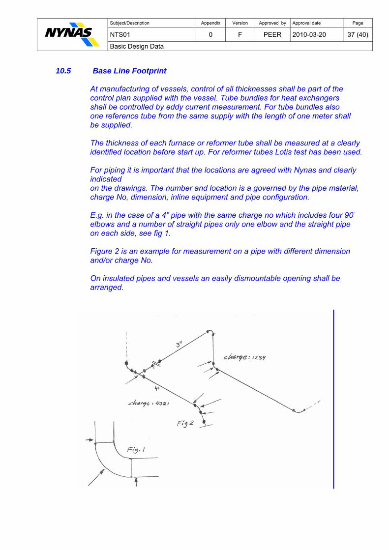
At manufacturing of vessels, control of all thicknesses shall be part of the control plan supplied with the vessel. Tube bundles for heat exchangers shall be controlled by eddy current measurement. For tube bundles also one reference tube from the same supply with the length of one meter shall be supplied. The thickness of each furnace or reformer tube shall be measured at a clearly identified location before start up. For reformer tubes Lotis test has been used. For piping it is important that the locations are agreed with Nynas and clearly indicated on the drawings. The number and location is a governed by the pipe material, charge No, dimension, inline equipment and pipe configuration. E.g. in the case of a 4” pipe with the same charge no which includes four 90◦
elbows and a number of straight pipes only one elbow and the straight pipe on each side, see fig 1. Figure 2 is an example for measurement on a pipe with different dimension and/or charge No. On insulated pipes and vessels an easily dismountable opening shall be arranged.
Subject/Description Appendix Version Approved by Approval date Page
NTS01 0 F PEER 2010-03-20 38 (40) Basic Design Data
Section 11 - Emission
11.1 Hydrocarbons-HC According to Local environmental regulation
emission from valve, flanges and itemised equipment, tankage sewers etc. shall be measured and recorded. To minimise emission at least the general recommendation set forth in NTS16 must be applied.
11.1.1 All valves: Shall be numbered acc. to NTS14.
11.1.2 Mechanical seals: Designed for ”<100 ppm” with guarantee ”<500 ppm”.
11.1.3 Plunger type pumps: Membrane, alternatively drained/vented to flare distance
piece.
11.1.4 Reciprocating compr: Distance piece vented to flare with leak rate measuring device.
11.1.5 Valves: As per NTS16.
11.1.6 Control valves: ”<500 ppm certificate”, ”<100 ppm” when available.
11.1.7 Live load: Stuffing box for axial stem Double O-ring for rotating stem.
11.1.8 All emission levels: According to EPA method 21.
11.2 NOx for Fuels 11.2.1 Fuel oil: Low - NOx burners shall be installed with best available technology and in corporation with Company. 11.2.2 Emission targets: Gas firing should be ≤ 20mg/MJ. Fuel oil firing (2.1.1) should be ≤ 80mg/MJ. 11.3 Carbon Dioxide – CO2 11.3.1 All CO2 emitting processes shall be monitored, usually by measuring the mass flow of fuel, and be according to NFS 2007:5, or later version, from the Naturvårdsverket. For all changes to existing fuel flow measurements or new CO2 emitting installations an uncertainty calculation for the measurement system, within a 95% confidence level shall be performed.
Subject/Description Appendix Version Approved by Approval date Page
NTS01 0 F PEER 2010-03-20 39 (40) Basic Design Data
Environmental responsible at HSE department and Instrument engineer at Reliability department has to be informed early in the Project.
Signals used for the measurement system shall be in DCS and easy to verify within Nynas.
11.4 Heat Recovery
11.4.1 Waste heat recovery: Shall be considered for - air preheating - steam production - town heating system.
Section 12 – Life Cycle Costs (LCC)
12.1 Definition: All costs associated with the acquisition and
ownership of a system over its full life.
12.2 Deviations: From Nynas Technical Standards (NTS) or the Manufacturer List shall always be accompanied by a
LCC-analysis. 12.3 Calculation: Shall include at least the following steps: design,
installation, operation, maintenance and disposal of the product. These steps may be further subdivided until the cost of each element can be defined.
Acceptance by Company required.
12.4 Req’d in all quotations: Equipment expected total life (years) based on values given in the datasheets. Pre-commissioning spares.
Maintenance recommendations for - routine maintenance activities - 4-year maintenance periods Spare parts recommendation for - routine activities - 4 year maintenance periods - life time spare parts (to be bought later) according to expected total life Utility Consumption Disposal of the Product
Subject/Description Appendix Version Approved by Approval date Page
NTS01 0 F PEER 2010-03-20 40 (40) Basic Design Data
Section 13 - Technical Standards
13.1 Register: NTS00 Nynas Technical Standard Including where to find the standards 13.2 NTS: NTS01 Basic Design Data NTS02 Drawing References NTS10 Nynas 8-Step Model for Project Risk Management NTS11 Protective Coatings NTS14 Code and Numbering NTS16 Gaskets NTS18 Electrical General Specification NTS25 Vessels and Reactors NTS36 Winterizing, Heating and Insulation NTS38 Piping General NTS38 Piping, Appendix 1, PMA NTS38 Piping, Appendix 2, Material Selection NTS38 Piping, Appendix 3, Standard Assembly Drawings NTS38 Piping, Appendix 4, DIN Old Spec. NTS38 Piping, Appendix 5, Fibreglass Epoxy Pipe Specification NTS38 Piping, Appendix 6, Hot Tap Guideline NTS38 Piping, Appendix 7, Guidelines for Bracing of Pipe Branches NTS39 Instrumentation NTS45 Operator Interface Configuration NTS46 Cad Manual NTS47 Manufacturer List 13.3 References: CAD Drawings, Templates
Masterinfo/Standards - Guidelines/N02 – Templates/N02 - Drawing Templates
Particular Material Appraisals Masterinfo/Standards - Guidelines/N01 – Standards/N01 - PMA