ntc thermistor assemblies - vishay · pdf filentc thermistor assemblies ntc thermistor...
TRANSCRIPT
Document Number: 33012 For technical questions, contact: [email protected] www.vishay.comRevision: 23-Oct-01 17
NTC Thermistor AssembliesVishay Dale
NTC Thermistor Assemblies
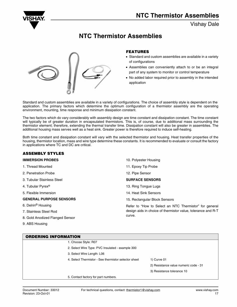
FEATURES• Standard and custom assemblies are available in a variety
of configurations
• Assemblies can conveniently attach to or be an integralpart of any system to monitor or control temperature
• No added labor required prior to assembly in the intendedapplication
Standard and custom assemblies are available in a variety of configurations. The choice of assembly style is dependent on theapplication. The primary factors which determine the optimum configuration of a thermistor assembly are the operatingenvironment, mounting, time response and minimum dissipation constant.
The two factors which do vary considerably with assembly design are time constant and dissipation constant. The time constantwill typically be of greater duration in encapsulated thermistors. This is, of course, due to additional mass surrounding thethermistor element; therefore, extending the thermal transfer time. Dissipation constant will also be greater in assemblies. Theadditional housing mass serves well as a heat sink. Greater power is therefore required to induce self-heating.
Both time constant and dissipation constant will vary with the selected thermistor and housing. Heat transfer properties of thehousing, thermistor location, mass and wire type determine these constants. It is recommended to evaluate or consult the factoryin applications where TC and DC are critical.
ASSEMBLY STYLES
IMMERSION PROBES
1. Thread Mounted
2. Penetration Probe
3. Tubular Stainless Steel
4. Tubular Pyrex®
5. Flexible Immersion
GENERAL PURPOSE SENSORS
6. Delrin® Housing
7. Stainless Steel Rod
8. Gold Anodized Flanged Sensor
9. ABS Housing
10. Polyester Housing
11. Epoxy Tip Probe
12. Pipe Sensor
SURFACE SENSORS
13. Ring Tongue Lugs
14. Heat Sink Sensors
15. Rectangular Block Sensors
Refer to “How to Select an NTC Thermistor” for generaldesign aids in choice of thermistor value, tolerance and R-Tcurve.
ORDERING INFORMATION1. Choose Style: R07
2. Select Wire Type: PVC Insulated - example 300
3. Select Wire Length: L06
4. Select Thermistor - See thermistor selector sheet 1) Curve 01
2) Resistance value numeric code - 31
3) Resistance tolerance 10
5. Contact factory for part numbers.
www.vishay.com For technical questions, contact: [email protected] Document Number: 3301218 Revision: 23-Oct-01
NTC Thermistor AssembliesVishay Dale NTC Thermistor Assemblies
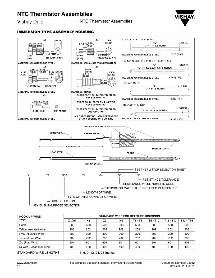
IMMERSION TYPE ASSEMBLY HOUSING
STANDARD WIRE LENGTHS: 3, 6, 9, 12, 24, 36 Inches
HOOK-UP WIRETYPE
STANDARD WIRE FOR HEX/TUBE HOUSINGS
X1/X5 X2 X3 X4 T1 - T4 T5 - T10 T11 - T12 T13 - T14
Cable 508 503 503 503 508 503 503 508
Teflon Insulated Wire 208 202 202 202 208 202 202 208
PVC Insulated Wire 300 300 300 300 300 300 300 300
Twisted Pair Wire 702 702 702 702 702 702 702 702
Zip (Flat) Wire 601 601 601 601 601 601 601 601
Ni Wire, Teflon Insulated 400 400 400 400 400 400 400 400
LEAD TYPE SHRINK WRAP
PROBE + HEX HOUSING
LEAD LENGTH
LEAD TYPE
SHRINK WRAP
PROBE
THERMISTOR
“L”“L” = 1.15, 3.6 INCHES
1/8 [3.18]
01.05 [2.67]MATERIAL #304 STAINLESS STEEL
“L”“L” = 1, 1.5, 2.5, 3, 4, 6, 8 INCHES
0.168 [4.27]MATERIAL #304 STAINLESS STEEL
“L”“L” = 2.5, 6 INCHES
1/4 [6.35]
0.230 [5.84]MATERIAL #304 STAINLESS STEEL
“L”“L” = 1.25, 6.25 INCHES
MATERIAL #304 STAINLESS STEEL
1/8 [3.18]
0.105 [2.67]
1/8” PROBE
25 20 0.38[6.35] [5.08] [9.65]
0.438[11.12]
0.160[4.06] THREAD 1/8 NPT
1/8” PROBE
MATERIAL: #303 STAINLESS STEEL
0.25 0.20 0.38[9.65]
0.160[4.06] THREAD 1/8-27-NPT
3/16” PROBE
0.438[11.12]
MATERIAL: #303 & #304 STAINLESS STEEL
0.475[12.06]0.188
[4.78]0.438
[11.12]0.156[3.96]
1/8-27-NPT1/4-20-NC TAP
0.563[14.3]
MATERIAL: #304 STAINLESS STEEL
0.295[7.49]
0.938[23.82]
MATERIAL: BRASS
MATERIAL: #303 STAINLESS STEEL
0.650[16.51]
0.30[7.62]
0.160 [4.06]
3/16 [4.78]
0.960[24.38]
0.312[7.92]
X1 X2
X3 X4
X5
T1 = 1” T2 = 1.5” T3 = 3” T4 = 6”
T5 = 1.5” T6 = 2.5” T7 = 3” T8 = 4” T9 = 6” T10 = 8”
T11 = 2.5” T12 = 6”
T13 = 1.25” T14 = 6.25”
TUBES T1, T2, T3, T4, T13, T14 FIT TOHEX BUSHING “X1”
TUBES T5, T6, T7, T8, T9, T10 FIT TOHEX BUSHING “X2”
TUBES T1, T2, T3, T4, T13, T14 FIT TOCOUPLING “X5”
ALL TUBES MAY BE USED INDEPENDENTOF ANY BUSHING OR COUPLING
X1 T1 300 L24 04 33 C3
RESISTANCE TOLERANCE
RESISTANCE VALUE NUMERIC CODE
THERMISTOR MATERIAL CURVE USED IN ASSEMBLY
LENGTH OF WIRE
TYPE OF INTERCONNECTION WIRE
TUBE SELECTION
HEX BUSHING/PROBE SELECTION
SEE THERMISTOR SELECTION SHEET
NTC Thermistor AssembliesNTC Thermistor Assemblies Vishay Dale
Document Number: 33012 For technical questions, contact: [email protected] www.vishay.comRevision: 23-Oct-01 19
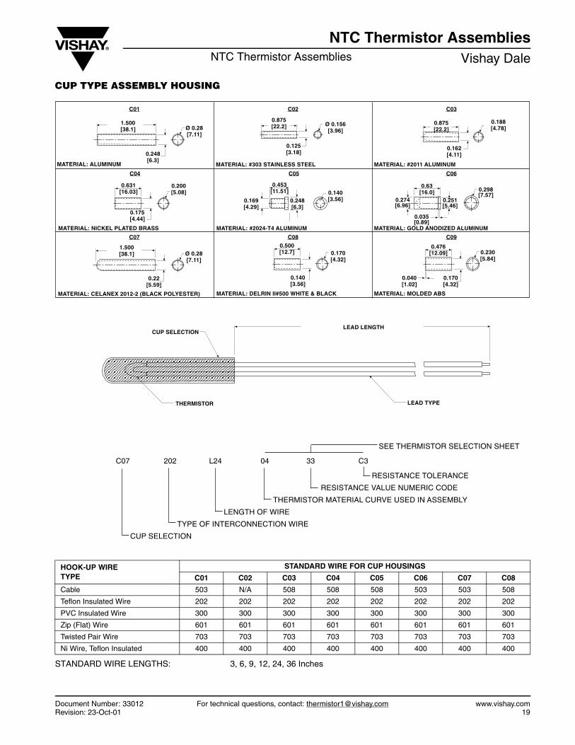
CUP TYPE ASSEMBLY HOUSING
STANDARD WIRE LENGTHS: 3, 6, 9, 12, 24, 36 Inches
HOOK-UP WIRETYPE
STANDARD WIRE FOR CUP HOUSINGS
C01 C02 C03 C04 C05 C06 C07 C08
Cable 503 N/A 508 508 508 503 503 508
Teflon Insulated Wire 202 202 202 202 202 202 202 202
PVC Insulated Wire 300 300 300 300 300 300 300 300
Zip (Flat) Wire 601 601 601 601 601 601 601 601
Twisted Pair Wire 703 703 703 703 703 703 703 703
Ni Wire, Teflon Insulated 400 400 400 400 400 400 400 400
LEAD LENGTHCUP SELECTION
THERMISTOR LEAD TYPE
1.500[38.1] Ø 0.28
[7.11]
0.248[6.3]
C01
MATERIAL: ALUMINUM
C02
0.875[22.2] Ø 0.156
[3.96]
0.125[3.18]
MATERIAL: #303 STAINLESS STEEL
C03
0.875[22.2]
0.188[4.78]
0.162[4.11]
MATERIAL: #2011 ALUMINUM
C04
0.631[16.03]
0.200[5.08]
0.175[4.44]
MATERIAL: NICKEL PLATED BRASS
C05
0.453[11.51]
0.248[6.3]
0.169[4.29]
0.140[3.56]
0.63[16.0]
C06
0.251[5.46]
0.274[6.96]
0.035[0.89]
0.298[7.57]
MUNIMULA DEZIDONA DLOG :LAIRETAMMUNIMULA 4T-4202# :LAIRETAM
Ø 0.28[7.11]
1.500[38.1]
0.22[5.59]
MATERIAL: CELANEX 2012-2 (BLACK POLYESTER)
C07
0.500[12.7]
C08
0.170[4.32]
0.140[3.56]
MATERIAL: DELRIN II#500 WHITE & BLACK
C09
0.476[12.09] 0.230
[5.84]
MATERIAL: MOLDED ABS
0.170[4.32]
0.040[1.02]
C07 202 L24 04 33 C3
RESISTANCE TOLERANCE
RESISTANCE VALUE NUMERIC CODE
THERMISTOR MATERIAL CURVE USED IN ASSEMBLY
LENGTH OF WIRE
TYPE OF INTERCONNECTION WIRE
CUP SELECTION
SEE THERMISTOR SELECTION SHEET
www.vishay.com For technical questions, contact: [email protected] Document Number: 3301220 Revision: 23-Oct-01
NTC Thermistor AssembliesVishay Dale NTC Thermistor Assemblies
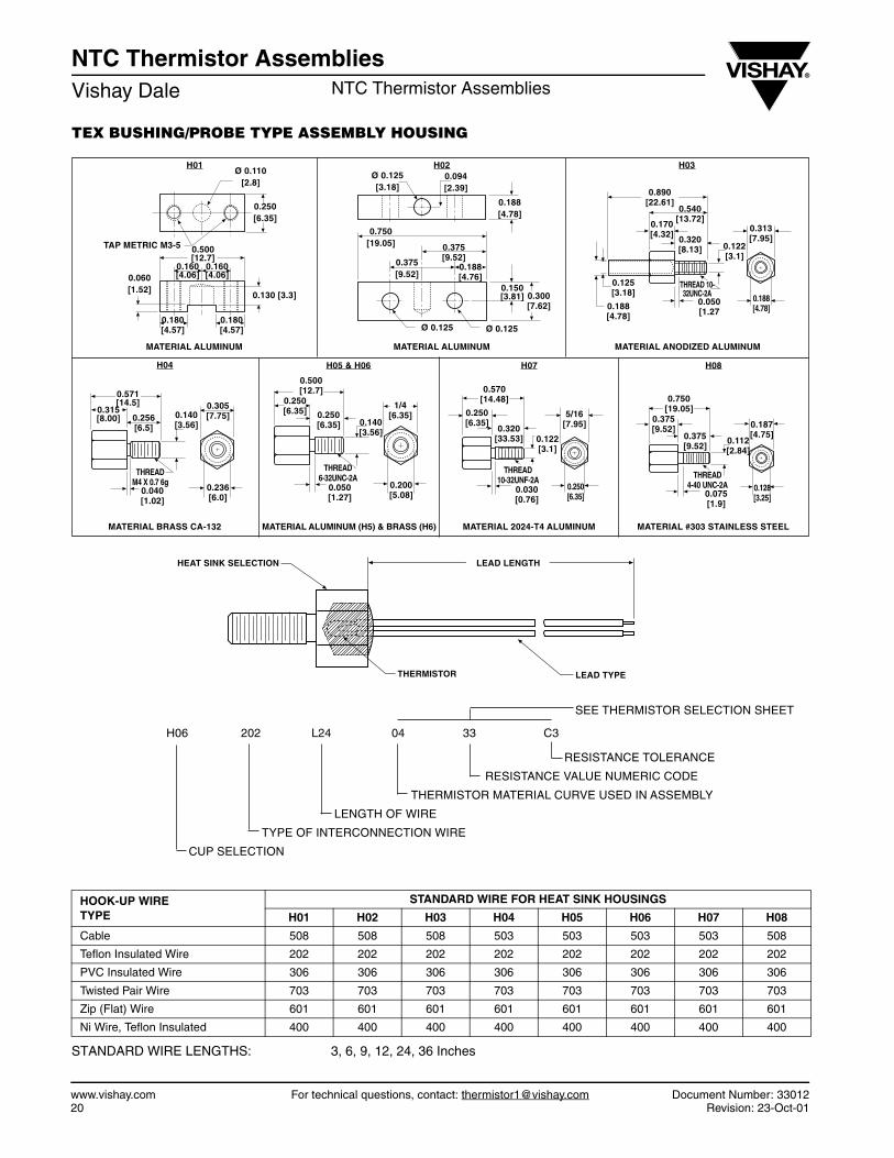
TEX BUSHING/PROBE TYPE ASSEMBLY HOUSING
STANDARD WIRE LENGTHS: 3, 6, 9, 12, 24, 36 Inches
HOOK-UP WIRETYPE
STANDARD WIRE FOR HEAT SINK HOUSINGS
H01 H02 H03 H04 H05 H06 H07 H08
Cable 508 508 508 503 503 503 503 508
Teflon Insulated Wire 202 202 202 202 202 202 202 202
PVC Insulated Wire 306 306 306 306 306 306 306 306
Twisted Pair Wire 703 703 703 703 703 703 703 703
Zip (Flat) Wire 601 601 601 601 601 601 601 601
Ni Wire, Teflon Insulated 400 400 400 400 400 400 400 400
H06 202 L24 04 33 C3
RESISTANCE TOLERANCE
RESISTANCE VALUE NUMERIC CODE
THERMISTOR MATERIAL CURVE USED IN ASSEMBLY
LENGTH OF WIRE
TYPE OF INTERCONNECTION WIRE
CUP SELECTION
LEAD LENGTH
LEAD TYPETHERMISTOR
HEAT SINK SELECTION
H01Ø 0.110
[2.8]
0.250[6.35]
TAP METRIC M3-5 0.500[12.7]
0.160[4.06]0.060
[1.52]0.130 [3.3]
0.160[4.06]
MATERIAL ALUMINUM
H02
MATERIAL ALUMINUM
Ø 0.125[3.18]
0.094[2.39]
0.188[4.78]
0.750[19.05] 0.375
[9.52]0.375[9.52]
0.150[3.81] 0.300
[7.62]
Ø 0.125 Ø 0.125
H03
MATERIAL ANODIZED ALUMINUM
0.540[13.72]
0.180[4.57]
0.180[4.57]
0.188[4.76]
0.890[22.61]
0.170[4.32]
0.320[8.13] 0.122
[3.1]
0.125[3.18]
0.188[4.78]
0.050[1.27
THREAD 10-32UNC-2A
0.313[7.95]
0.188[4.78]
H04 H05 & H06 H07 H08
MATERIAL BRASS CA-132 MATERIAL ALUMINUM (H5) & BRASS (H6) MATERIAL 2024-T4 ALUMINUM MATERIAL #303 STAINLESS STEEL
0.571[14.5]
0.315[8.00] 0.256
[6.5]0.140[3.56]
0.305[7.75]
0.236[6.0]
0.040[1.02]
THREADM4 X 0.7 6g
0.500[12.7]
0.250[6.35] 0.250
[6.35] 0.140[3.56]
0.050[1.27]
0.200[5.08]
1/4[6.35]
0.570[14.48]
0.250[6.35]
0.320[33.53] 0.122
[3.1]
5/16[7.95]
0.250[6.35]
0.030[0.76]
THREAD6-32UNC-2A
THREAD10-32UNF-2A
0.750[19.05]
0.375[9.52]
0.375[9.52]
0.187[4.75]
0.112[2.84]
0.075[1.9]
THREAD4-40 UNC-2A 0.128
[3.25]
SEE THERMISTOR SELECTION SHEET
NTC Thermistor AssembliesNTC Thermistor Assemblies Vishay Dale
Document Number: 33012 For technical questions, contact: [email protected] www.vishay.comRevision: 23-Oct-01 21
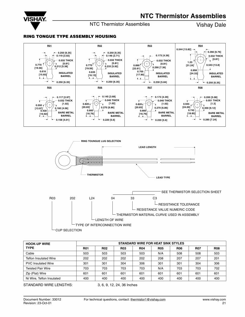
RING TONGUE TYPE ASSEMBLY HOUSING
STANDARD WIRE LENGTHS: 3, 6, 9, 12, 24, 36 Inches
HOOK-UP WIRETYPE
STANDARD WIRE FOR HEAT SINK STYLES
R01 R02 R03 R04 R05 R06 R07 R08
Cable 503 503 503 503 N/A 508 508 503
Teflon Insulated Wire 202 202 202 202 208 207 207 201
PVC Insulated Wire 301 301 304 306 301 301 304 306
Twisted Pair Wire 703 703 703 703 N/A 703 703 702
Zip (Flat) Wire 601 601 601 601 601 601 601 601
Ni Wire, Teflon Insulated 400 400 400 400 400 400 400 400
RING TOUNGUE LUG SELECTION
LEAD LENGTH
LEAD TYPETHERMISTOR
R01
0.250 [6.35]0.119 [3.02]
0.032 THICK[0.81]
0.212 [5.38]
0.250 [6.35]
0.770[19.56]
0.616[15.65]
R02
0.250 [6.35]0.146 [3.71]
0.032 THICK[0.81]
0.233 [5.92]
INSULATEDBARREL
INSULATEDBARREL
0.250 [6.35]
0.770[19.56]
0.635[16.13]
R03
0.173 [4.39]
0.032 THICK[0.81]
0.290 [7.36]
0.230 [5.84]
INSULATEDBARREL
0.890[22.61]
0.705[17.90]
R04
0.266 [6.76]0.544 [13.82]
0.032 THICK[0.81]
0.543 [13.8]
0.250 [6.35]
INSULATEDBARREL
1.23[31.24]
0.958[24.33]
R05 R06 R07 R08
BARE METALBARREL
BARE METALBARREL
BARE METALBARREL
BARE METALBARREL
0.117 [2.97]0.032 THICK
[1.02]
0.160 [4.06]
0.158 [4.01]
0.550[13.97]
0.430[10.92]
0.145 [3.68]
0.040 THICK[1.02]
0.270 [6.86]
0.220 [5.6]
0.820[20.83]
0.660[16.76]
0.173 [4.39]0.040 THICK
[1.02]
0.270 [6.86]
0.220 [5.6]
0.820[20.83]
0.660[16.76]
0.200 [5.08]0.051 THICK
[1.3]
0.359 [9.12]
0.285 [7.24]
0.945[24.00]
0.742[18.85]
R03 202 L24 04 33 C3
RESISTANCE TOLERANCE
RESISTANCE VALUE NUMERIC CODE
THERMISTOR MATERIAL CURVE USED IN ASSEMBLY
LENGTH OF WIRE
TYPE OF INTERCONNECTION WIRE
CUP SELECTION
SEE THERMISTOR SELECTION SHEET
www.vishay.com For technical questions, contact: [email protected] Document Number: 3301222 Revision: 23-Oct-01
NTC Thermistor AssembliesVishay Dale NTC Thermistor Assemblies
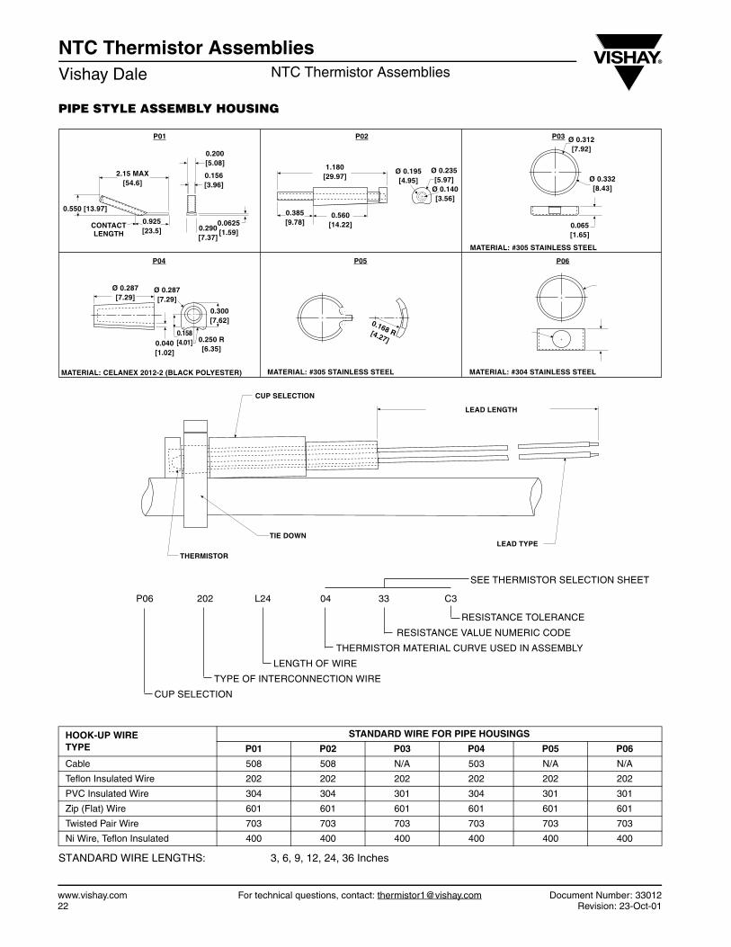
PIPE STYLE ASSEMBLY HOUSING
STANDARD WIRE LENGTHS: 3, 6, 9, 12, 24, 36 Inches
HOOK-UP WIRETYPE
STANDARD WIRE FOR PIPE HOUSINGS
P01 P02 P03 P04 P05 P06
Cable 508 508 N/A 503 N/A N/A
Teflon Insulated Wire 202 202 202 202 202 202
PVC Insulated Wire 304 304 301 304 301 301
Zip (Flat) Wire 601 601 601 601 601 601
Twisted Pair Wire 703 703 703 703 703 703
Ni Wire, Teflon Insulated 400 400 400 400 400 400
THERMISTOR
CUP SELECTION
TIE DOWNLEAD TYPE
LEAD LENGTH
2.15 MAX[54.6]
0.200[5.08]
0.156[3.96]
0.550 [13.97]
0.0625[1.59]
0.925[23.5]
CONTACTLENGTH
0.290[7.37]
1.180[29.97]
0.560[14.22]
0.385[9.78]
Ø 0.195[4.95]
Ø 0.235[5.97]
Ø 0.140[3.56]
Ø 0.312[7.92]
Ø 0.332[8.43]
0.065[1.65]
MATERIAL: #305 STAINLESS STEEL
Ø 0.287[7.29]
Ø 0.287[7.29]
0.300[7.62]
0.250 R[6.35]
0.158[4.01]0.040
[1.02]
MATERIAL: CELANEX 2012-2 (BLACK POLYESTER)
0.168 R[4.27]
MATERIAL: #305 STAINLESS STEEL
P01 P02 P03
P04 P05
P06 202 L24 04 33 C3
RESISTANCE TOLERANCE
RESISTANCE VALUE NUMERIC CODE
THERMISTOR MATERIAL CURVE USED IN ASSEMBLY
LENGTH OF WIRE
TYPE OF INTERCONNECTION WIRE
CUP SELECTION
SEE THERMISTOR SELECTION SHEET
MATERIAL: #304 STAINLESS STEEL
P06
NTC Thermistor AssembliesNTC Thermistor Assemblies Vishay Dale
Document Number: 33012 For technical questions, contact: [email protected] www.vishay.comRevision: 23-Oct-01 23
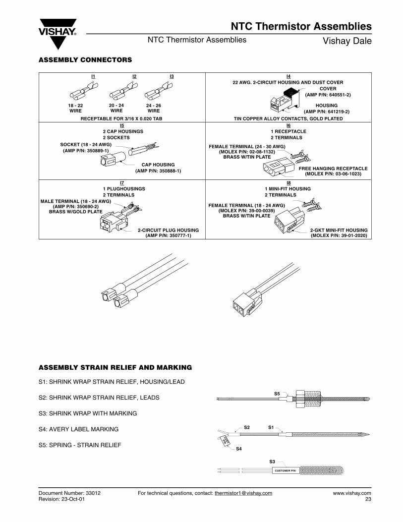
ASSEMBLY CONNECTORS
ASSEMBLY STRAIN RELIEF AND MARKING
S1: SHRINK WRAP STRAIN RELIEF, HOUSING/LEAD
S2: SHRINK WRAP STRAIN RELIEF, LEADS
S3: SHRINK WRAP WITH MARKING
S4: AVERY LABEL MARKING
S5: SPRING - STRAIN RELIEF
I4
I6
I8I7
I5
I1 I2 I3
1 PLUGHOUSINGS2 TERMINALS
2 CAP HOUSINGS2 SOCKETS
18 - 22 WIRE
20 - 24 WIRE
24 - 26 WIRE
RECEPTABLE FOR 3/16 X 0.020 TAB
SOCKET (18 - 24 AWG)(AMP P/N: 350889-1)
CAP HOUSING(AMP P/N: 350888-1)
MALE TERMINAL (18 - 24 AWG)(AMP P/N: 350690-2)
BRASS W/GOLD PLATEFEMALE TERMINAL (18 - 24 AWG)
(MOLEX P/N: 39-00-0039)BRASS W/TIN PLATE
1 MINI-FIT HOUSING2 TERMINALS
2-CIRCUIT PLUG HOUSING(AMP P/N: 350777-1)
2-GKT MINI-FIT HOUSING(MOLEX P/N: 39-01-2020)
FEMALE TERMINAL (24 - 30 AWG)(MOLEX P/N: 02-08-1132)
BRASS W/TIN PLATE
FREE HANGING RECEPTACLE(MOLEX P/N: 03-06-1023)
1 RECEPTACLE2 TERMINALS
TIN COPPER ALLOY CONTACTS, GOLD PLATED
HOUSING(AMP P/N: 641219-2)
COVER(AMP P/N: 640551-2)
22 AWG. 2-CIRCUIT HOUSING AND DUST COVER
CU
ST.
P/N
CUSTOMER P/N
S5
S1S2
S3
S4
www.vishay.com For technical questions, contact: [email protected] Document Number: 3301224 Revision: 23-Oct-01
NTC Thermistor AssembliesVishay Dale NTC Thermistor Assemblies
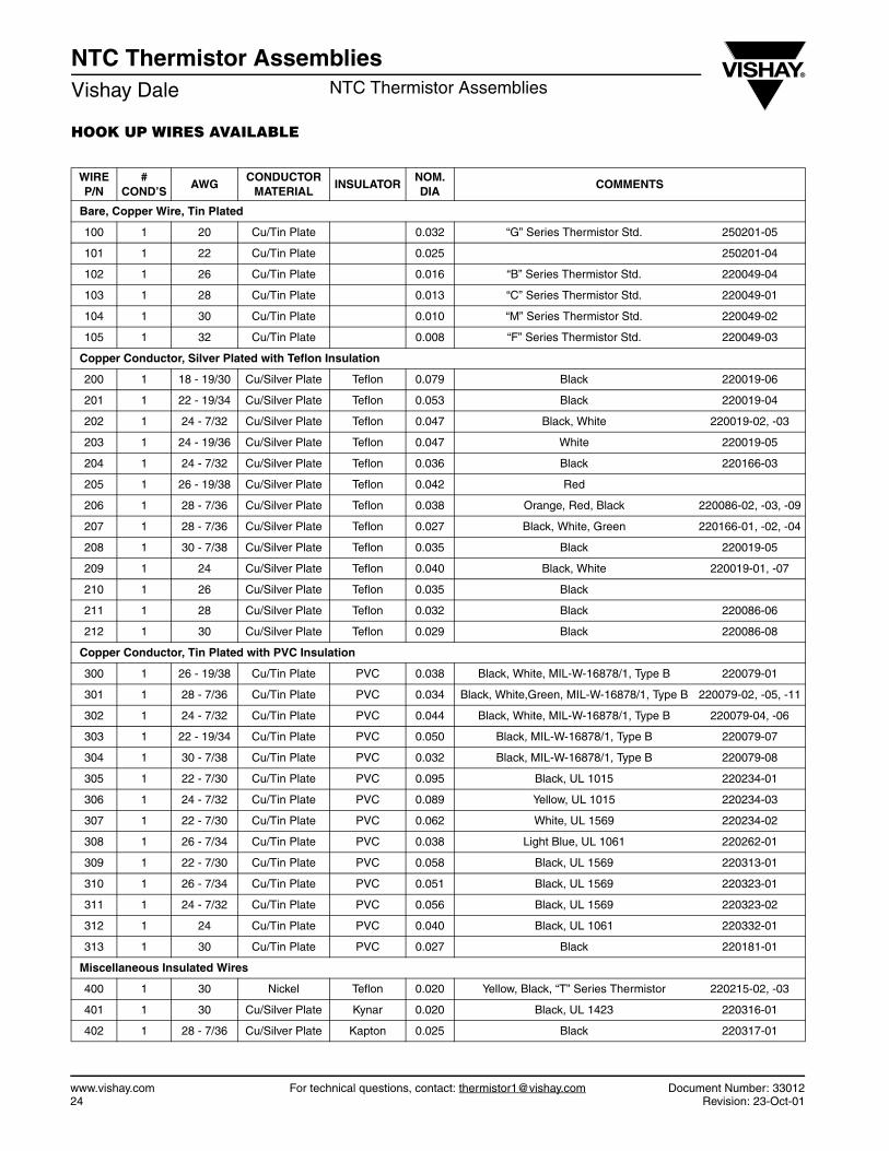
HOOK UP WIRES AVAILABLE
WIREP/N
#COND’S
AWGCONDUCTOR
MATERIALINSULATOR
NOM.DIA
COMMENTS
Bare, Copper Wire, Tin Plated
100 1 20 Cu/Tin Plate 0.032 “G” Series Thermistor Std. 250201-05
101 1 22 Cu/Tin Plate 0.025 250201-04
102 1 26 Cu/Tin Plate 0.016 “B” Series Thermistor Std. 220049-04
103 1 28 Cu/Tin Plate 0.013 “C” Series Thermistor Std. 220049-01
104 1 30 Cu/Tin Plate 0.010 “M” Series Thermistor Std. 220049-02
105 1 32 Cu/Tin Plate 0.008 “F” Series Thermistor Std. 220049-03
Copper Conductor, Silver Plated with Teflon Insulation
200 1 18 - 19/30 Cu/Silver Plate Teflon 0.079 Black 220019-06
201 1 22 - 19/34 Cu/Silver Plate Teflon 0.053 Black 220019-04
202 1 24 - 7/32 Cu/Silver Plate Teflon 0.047 Black, White 220019-02, -03
203 1 24 - 19/36 Cu/Silver Plate Teflon 0.047 White 220019-05
204 1 24 - 7/32 Cu/Silver Plate Teflon 0.036 Black 220166-03
205 1 26 - 19/38 Cu/Silver Plate Teflon 0.042 Red
206 1 28 - 7/36 Cu/Silver Plate Teflon 0.038 Orange, Red, Black 220086-02, -03, -09
207 1 28 - 7/36 Cu/Silver Plate Teflon 0.027 Black, White, Green 220166-01, -02, -04
208 1 30 - 7/38 Cu/Silver Plate Teflon 0.035 Black 220019-05
209 1 24 Cu/Silver Plate Teflon 0.040 Black, White 220019-01, -07
210 1 26 Cu/Silver Plate Teflon 0.035 Black
211 1 28 Cu/Silver Plate Teflon 0.032 Black 220086-06
212 1 30 Cu/Silver Plate Teflon 0.029 Black 220086-08
Copper Conductor, Tin Plated with PVC Insulation
300 1 26 - 19/38 Cu/Tin Plate PVC 0.038 Black, White, MIL-W-16878/1, Type B 220079-01
301 1 28 - 7/36 Cu/Tin Plate PVC 0.034 Black, White,Green, MIL-W-16878/1, Type B 220079-02, -05, -11
302 1 24 - 7/32 Cu/Tin Plate PVC 0.044 Black, White, MIL-W-16878/1, Type B 220079-04, -06
303 1 22 - 19/34 Cu/Tin Plate PVC 0.050 Black, MIL-W-16878/1, Type B 220079-07
304 1 30 - 7/38 Cu/Tin Plate PVC 0.032 Black, MIL-W-16878/1, Type B 220079-08
305 1 22 - 7/30 Cu/Tin Plate PVC 0.095 Black, UL 1015 220234-01
306 1 24 - 7/32 Cu/Tin Plate PVC 0.089 Yellow, UL 1015 220234-03
307 1 22 - 7/30 Cu/Tin Plate PVC 0.062 White, UL 1569 220234-02
308 1 26 - 7/34 Cu/Tin Plate PVC 0.038 Light Blue, UL 1061 220262-01
309 1 22 - 7/30 Cu/Tin Plate PVC 0.058 Black, UL 1569 220313-01
310 1 26 - 7/34 Cu/Tin Plate PVC 0.051 Black, UL 1569 220323-01
311 1 24 - 7/32 Cu/Tin Plate PVC 0.056 Black, UL 1569 220323-02
312 1 24 Cu/Tin Plate PVC 0.040 Black, UL 1061 220332-01
313 1 30 Cu/Tin Plate PVC 0.027 Black 220181-01
Miscellaneous Insulated Wires
400 1 30 Nickel Teflon 0.020 Yellow, Black, “T” Series Thermistor 220215-02, -03
401 1 30 Cu/Silver Plate Kynar 0.020 Black, UL 1423 220316-01
402 1 28 - 7/36 Cu/Silver Plate Kapton 0.025 Black 220317-01
NTC Thermistor AssembliesNTC Thermistor Assemblies Vishay Dale
Document Number: 33012 For technical questions, contact: [email protected] www.vishay.comRevision: 23-Oct-01 25
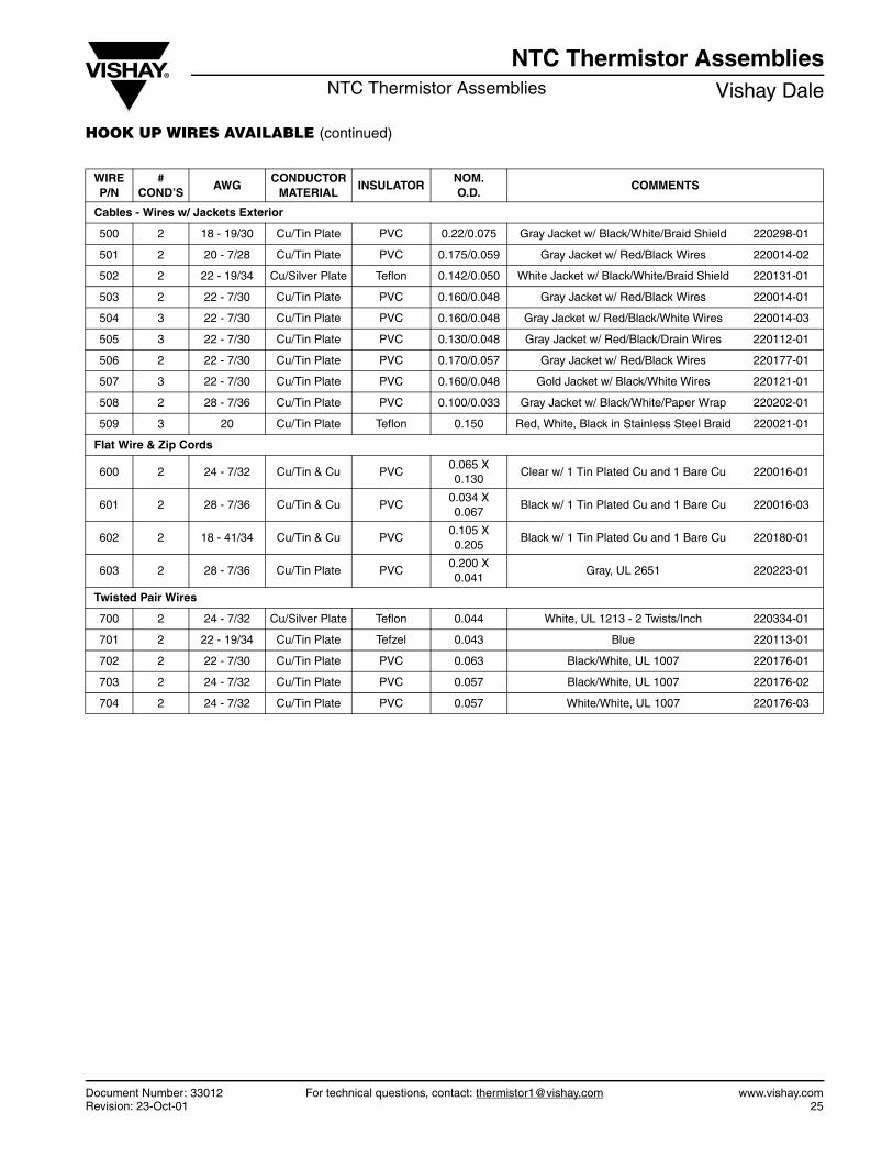
HOOK UP WIRES AVAILABLE (continued)
WIREP/N
#COND’S
AWGCONDUCTOR
MATERIALINSULATOR
NOM.O.D.
COMMENTS
Cables - Wires w/ Jackets Exterior
500 2 18 - 19/30 Cu/Tin Plate PVC 0.22/0.075 Gray Jacket w/ Black/White/Braid Shield 220298-01
501 2 20 - 7/28 Cu/Tin Plate PVC 0.175/0.059 Gray Jacket w/ Red/Black Wires 220014-02
502 2 22 - 19/34 Cu/Silver Plate Teflon 0.142/0.050 White Jacket w/ Black/White/Braid Shield 220131-01
503 2 22 - 7/30 Cu/Tin Plate PVC 0.160/0.048 Gray Jacket w/ Red/Black Wires 220014-01
504 3 22 - 7/30 Cu/Tin Plate PVC 0.160/0.048 Gray Jacket w/ Red/Black/White Wires 220014-03
505 3 22 - 7/30 Cu/Tin Plate PVC 0.130/0.048 Gray Jacket w/ Red/Black/Drain Wires 220112-01
506 2 22 - 7/30 Cu/Tin Plate PVC 0.170/0.057 Gray Jacket w/ Red/Black Wires 220177-01
507 3 22 - 7/30 Cu/Tin Plate PVC 0.160/0.048 Gold Jacket w/ Black/White Wires 220121-01
508 2 28 - 7/36 Cu/Tin Plate PVC 0.100/0.033 Gray Jacket w/ Black/White/Paper Wrap 220202-01
509 3 20 Cu/Tin Plate Teflon 0.150 Red, White, Black in Stainless Steel Braid 220021-01
Flat Wire & Zip Cords
600 2 24 - 7/32 Cu/Tin & Cu PVC0.065 X 0.130
Clear w/ 1 Tin Plated Cu and 1 Bare Cu 220016-01
601 2 28 - 7/36 Cu/Tin & Cu PVC0.034 X 0.067
Black w/ 1 Tin Plated Cu and 1 Bare Cu 220016-03
602 2 18 - 41/34 Cu/Tin & Cu PVC0.105 X 0.205
Black w/ 1 Tin Plated Cu and 1 Bare Cu 220180-01
603 2 28 - 7/36 Cu/Tin Plate PVC0.200 X 0.041
Gray, UL 2651 220223-01
Twisted Pair Wires
700 2 24 - 7/32 Cu/Silver Plate Teflon 0.044 White, UL 1213 - 2 Twists/Inch 220334-01
701 2 22 - 19/34 Cu/Tin Plate Tefzel 0.043 Blue 220113-01
702 2 22 - 7/30 Cu/Tin Plate PVC 0.063 Black/White, UL 1007 220176-01
703 2 24 - 7/32 Cu/Tin Plate PVC 0.057 Black/White, UL 1007 220176-02
704 2 24 - 7/32 Cu/Tin Plate PVC 0.057 White/White, UL 1007 220176-03
www.vishay.com For technical questions, contact: [email protected] Document Number: 3301226 Revision: 23-Oct-01
NTC Thermistor AssembliesVishay Dale NTC Thermistor Assemblies
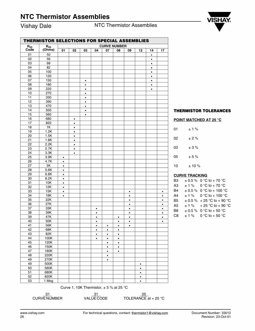
Curve 1, 10K Thermistor, ± 5 % at 25 °C
01 31 05CURVE NUMBER VALUE CODE TOLERANCE at + 25 °C
THERMISTOR SELECTIONS FOR SPECIAL ASSEMBLIESR25
CodeR25
(Ohms)CURVE NUMBER
01 02 03 04 07 08 09 12 14 1701 50 •02 56 •03 68 •04 82 •05 100 •06 120 •07 150 • •08 180 • •09 220 • •10 270 •11 330 •12 390 •13 470 •14 500 •15 560 •16 680 •17 820 •18 1K •19 1.2K •20 1.5K •21 1.8K •22 2.2K •23 2.7K •24 3.3K •25 3.9K •26 4.7K •27 5K •28 5.6K •29 6.8K •30 8.2K •31 10K •32 12K •33 15K • • •34 18K • • •35 22K • •36 27K • •37 33K • • •38 39K • • •39 47K • • • •40 50K • • • •41 56K • • • •42 68K • • •43 82K • • •44 100K • • •45 120K • •46 150K • •47 180K • •48 220K •49 270K •49 500K •50 560K •51 680K •52 820K •53 1 Meg •
THERMISTOR TOLERANCES
POINT MATCHED AT 25 °C
01 ± 1 %
02 ± 2 %
03 ± 3 %
05 ± 5 %
10 ± 10 %
CURVE TRACKINGB3 ± 0.5 % 0 °C to + 70 °CA3 ± 1 % 0 °C to + 70 °CB4 ± 0.5 % 0 °C to + 100 °CA4 ± 1 % 0 °C to + 100 °CB5 ± 0.5 % + 25 °C to + 90 °CA5 ± 1 % + 25 °C to + 90 °CB8 ± 0.5 % 0 °C to + 50 °CC8 ± 1 % 0 °C to + 50 °C