nsn alarm rectification doc
DESCRIPTION
NSN BTS alarm rectification documentTRANSCRIPT
Troubleshooting with the help of alarm tables
Purpose
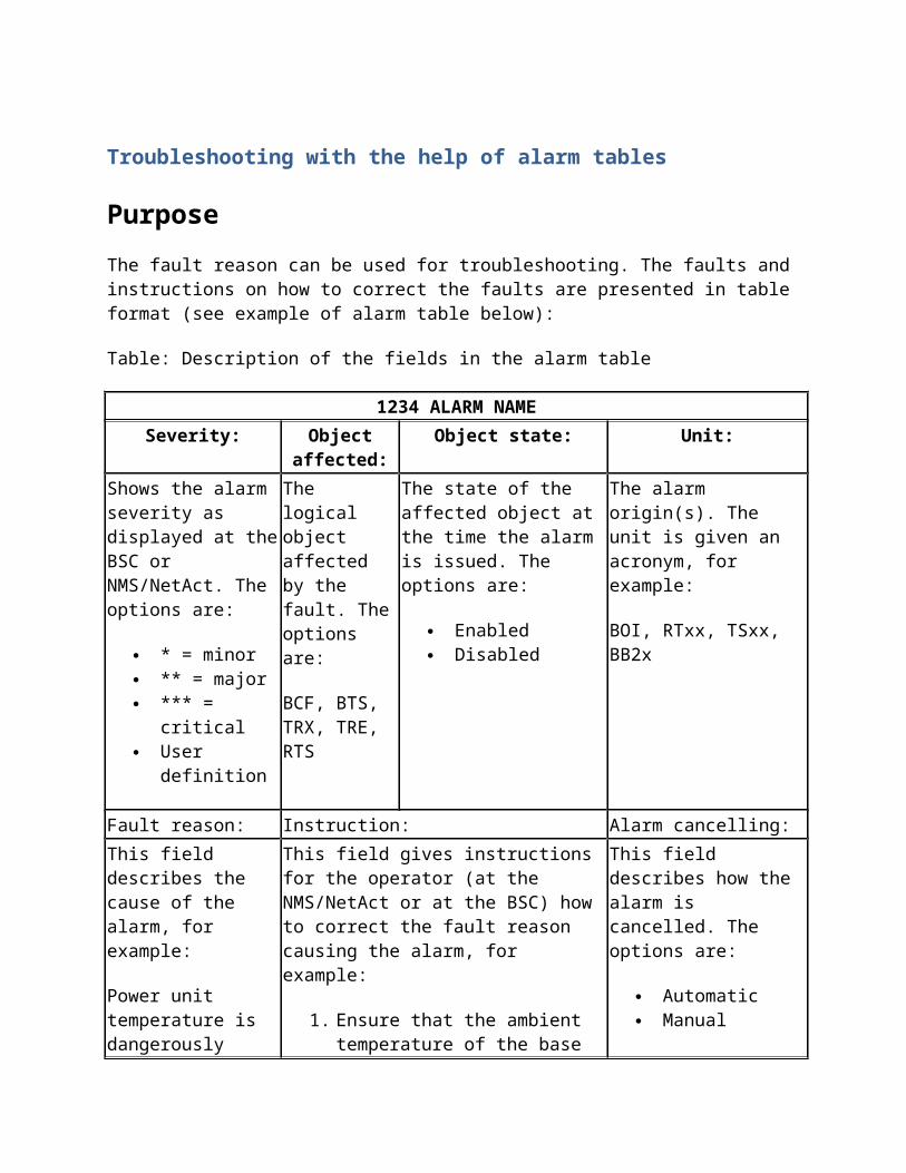
The fault reason can be used for troubleshooting. The faults and instructions on how to correct the faults are presented in table format (see example of alarm table below):
Table: Description of the fields in the alarm table
1234 ALARM NAME
Severity: Object affected:
Object state: Unit:
Shows the alarm severity as displayed at the BSC or NMS/NetAct. The options are:
* = minor ** = major *** = critical User definition
The logical object affected by the fault. The options are:
BCF, BTS, TRX, TRE, RTS
The state of the affected object at the time the alarm is issued. The options are:
Enabled Disabled
The alarm origin(s). The unit is given an acronym, for example:
BOI, RTxx, TSxx, BB2x
Fault reason: Instruction: Alarm cancelling:
This field describes the cause of the alarm, for example:
Power unit temperature is dangerously high.
This field gives instructions for the operator (at the NMS/NetAct or at the BSC) how to correct the fault reason causing the alarm, for example:
1. Ensure that the ambient temperature of the base station is within specified limits.
2. Check the cabinet fans.3. Replace the faulty power unit(s).
This field describes how the alarm is cancelled. The options are:
Automatic Manual
Note
When baseband hopping is used, alarms do not cancel automatically when a fault is corrected. Sector reset from Nokia BTS Manager or BTS lock/unlock from the BSC is required to clear the active alarms.
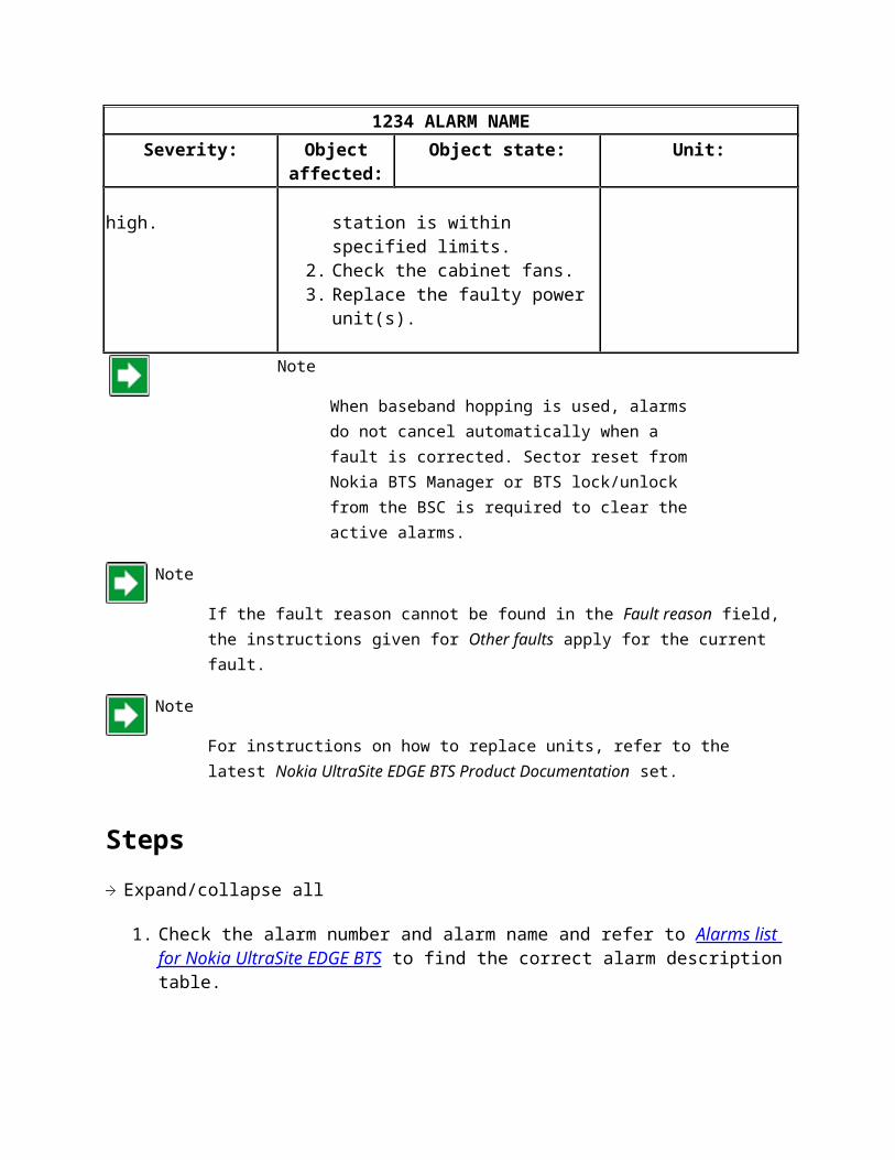
Note
If the fault reason cannot be found in the Fault reason field, the instructions given for Other faults apply for the current fault.
Note
For instructions on how to replace units, refer to the latest Nokia UltraSite EDGE BTS Product Documentation set.
Steps
Expand/collapse all
1. Check the alarm number and alarm name and refer to Alarms list for Nokia UltraSite EDGE BTS to find the correct alarm description table.
2. Find the fault reason in the Fault reason field in the alarm description table.3. Follow the instructions in the proposed order given in the Instruction field.
4. If the fault reason cannot be found in the Fault reason field, follow the instructions given for Other faults.
5. If there is no fault reason text with the alarm (see 1. in Figure 'Examples of active alarms as seen at the BSC'), refer to the correct alarm description table and follow the possible instructions given in the Instruction field.
7745 CHANNEL FAILURE RATE ABOVE DEFINED THRESHOLD
Meaning
The rate of calls terminating in failure on a channel is above thethreshold value set by the operator. The alarm is used to supervisethe functioning of traffic and signaling channels, and to detectthe possible faulty channels.
Supplementary information fields
1 indicates if the alarm is on the TCH or on the SDCCH channel 01: TCH 02: SDCCH
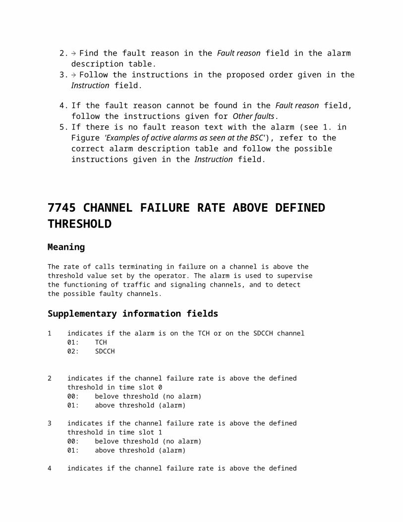
2 indicates if the channel failure rate is above the defined threshold in time slot 0 00: belove threshold (no alarm) 01: above threshold (alarm)
3 indicates if the channel failure rate is above the defined threshold in time slot 1 00: belove threshold (no alarm) 01: above threshold (alarm)
4 indicates if the channel failure rate is above the defined threshold in time slot 2 00: belove threshold (no alarm) 01: above threshold (alarm)
5 indicates if the channel failure rate is above the defined threshold in time slot 3 00: belove threshold (no alarm) 01: above threshold (alarm)
6 indicates if the channel failure rate is above the defined threshold in time slot 4 00: belove threshold (no alarm) 01: above threshold (alarm)
7 indicates if the channel failure rate is above the defined threshold in time slot 5 00: belove threshold (no alarm) 01: above threshold (alarm)
8 indicates if the channel failure rate is above the defined threshold in time slot 6 00: belove threshold (no alarm) 01: above threshold (alarm)
9 indicates if the channel failure rate is above the defined threshold in time slot 7 00: belove threshold (no alarm) 01: above threshold (alarm)
10 time slot with the highest failure rate
11 subchannel identification TCH: 00: TCH/H -subchannel 0 01: TCH/H -subchannel 1 02: TCH/F -subchannel
subchannel identification SDCCH: 00 - 07: SDCCH -subchannel 0 - 7
12 proportion of TCH or SDCCH subchannel releases due to failure in all channel releases on a given channel during the measurement period
Instructions
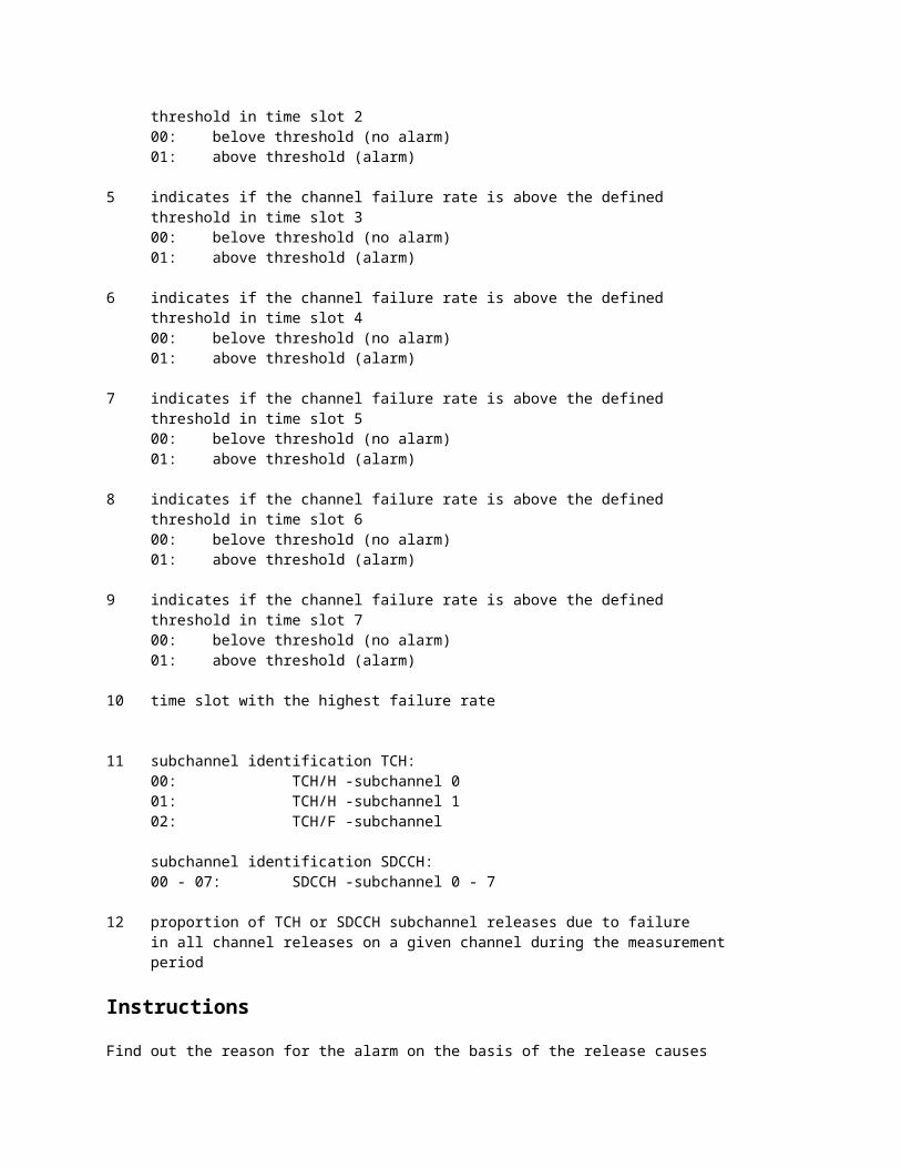
Find out the reason for the alarm on the basis of the release causesin channel release messages. Restore the channel by first locking itout of use and then unlocking it with the MML command ERS.
ZERS:<BTS>,<TRX>,<CH>:L; lock ZERS:<BTS>,<TRX>,<CH>:U; unlock
Check that the parameters affecting the alarm are reasonable.MML command EEO outputs the radio network supervision parameter values,EEN command modifies the parameter values.
Parameters, with their default values, affecting the alarm: ZEEN:TCHFR = TCH failure rate (20 %) SCHFR = SDCCH failure rate (80 %) PRDCFR = length of supervision period (60 min) CS = channel seizure threshold value (10)
SMBNT = supervision start time (08-00) EMBNT = supervision end time (18-00)
Cancelling
If the alarm requires no user actions, you can cancel it with theMML command EOR.
The system cancels the alarm automatically in connection with theuser's locking and unlocking commands, or, if the situation is solvedwithout user actions, after the current measurement period.
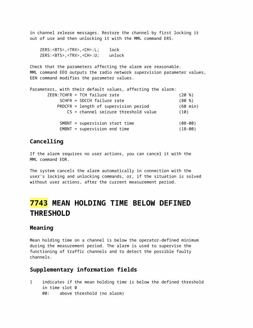
7743 MEAN HOLDING TIME BELOW DEFINED THRESHOLD
Meaning
Mean holding time on a channel is below the operator-defined minimumduring the measurement period. The alarm is used to supervise thefunctioning of traffic channels and to detect the possible faultychannels.
Supplementary information fields
1 indicates if the mean holding time is below the defined threshold in time slot 0 00: above threshold (no alarm) 01: below threshold (alarm)
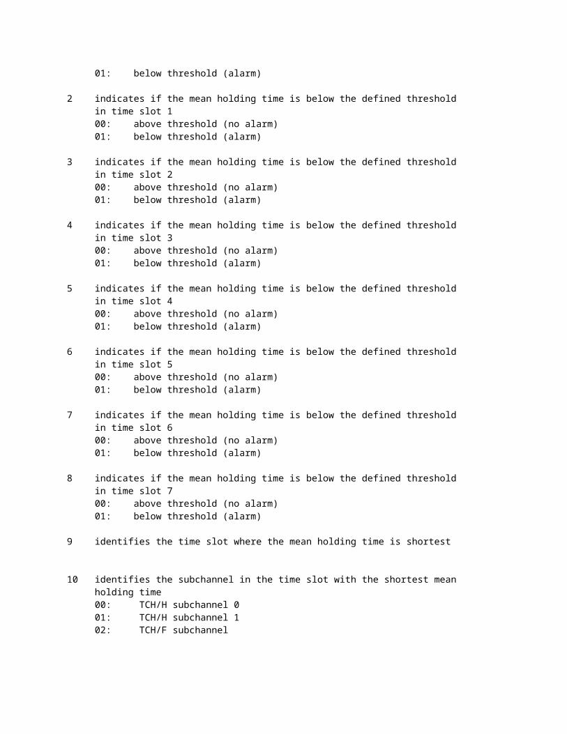
2 indicates if the mean holding time is below the defined threshold in time slot 1 00: above threshold (no alarm) 01: below threshold (alarm)
3 indicates if the mean holding time is below the defined threshold in time slot 2 00: above threshold (no alarm) 01: below threshold (alarm)
4 indicates if the mean holding time is below the defined threshold in time slot 3 00: above threshold (no alarm) 01: below threshold (alarm)
5 indicates if the mean holding time is below the defined threshold in time slot 4 00: above threshold (no alarm) 01: below threshold (alarm)
6 indicates if the mean holding time is below the defined threshold in time slot 5 00: above threshold (no alarm) 01: below threshold (alarm)
7 indicates if the mean holding time is below the defined threshold in time slot 6 00: above threshold (no alarm) 01: below threshold (alarm)
8 indicates if the mean holding time is below the defined threshold in time slot 7 00: above threshold (no alarm) 01: below threshold (alarm)
9 identifies the time slot where the mean holding time is shortest
10 identifies the subchannel in the time slot with the shortest mean holding time 00: TCH/H subchannel 0 01: TCH/H subchannel 1 02: TCH/F subchannel
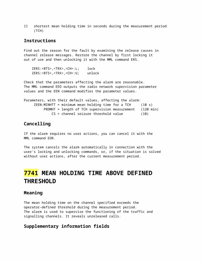
11 shortest mean holding time in seconds during the measurement period (TCH)
Instructions
Find out the reason for the fault by examining the release causes inchannel release messages. Restore the channel by first locking itout of use and then unlocking it with the MML command ERS.
ZERS:<BTS>,<TRX>,<CH>:L; lock ZERS:<BTS>,<TRX>,<CH>:U; unlock
Check that the parameters affecting the alarm are reasonable.The MML command EEO outputs the radio network supervision parametervalues and the EEN command modifies the parameter values.
Parameters, with their default values, affecting the alarm: ZEEN:MINHTT = minimum mean holding time for a TCH (10 s) PRDMHT = length of TCH supervision measurement (120 min) CS = channel seizure threshold value (10)
Cancelling
If the alarm requires no user actions, you can cancel it with theMML command EOR.
The system cancels the alarm automatically in connection with theuser's locking and unlocking commands, or, if the situation is solvedwithout user actions, after the current measurement period.
7741 MEAN HOLDING TIME ABOVE DEFINED THRESHOLD
Meaning
The mean holding time on the channel specified exceeds theoperator-defined threshold during the measurement period.The alarm is used to supervise the functioning of the traffic andsignalling channels. It reveals unreleased calls.
Supplementary information fields
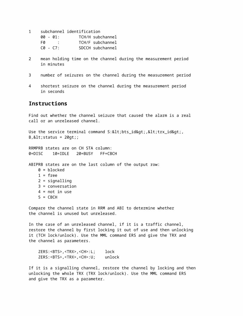
1 subchannel identification 00 - 01: TCH/H subchannel F0 : TCH/F subchannel C0 - C7: SDCCH subchannel
2 mean holding time on the channel during the measurement period in minutes
3 number of seizures on the channel during the measurement period
4 shortest seizure on the channel during the measurement period in seconds
Instructions
Find out whether the channel seizure that caused the alarm is a realcall or an unreleased channel.
Use the service terminal command S:<bts_id>,<trx_id>,B,<status = 20gt;;
RRMPRB states are on CH STA column:0=DISC 10=IDLE 20=BUSY FF=CBCH
ABIPRB states are on the last column of the output row: 0 = blocked 1 = free 2 = signalling 3 = conversation 4 = not in use 5 = CBCH
Compare the channel state in RRM and ABI to determine whetherthe channel is unused but unreleased.
In the case of an unreleased channel, if it is a traffic channel,restore the channel by first locking it out of use and then unlockingit (TCH lock/unlock). Use the MML command ERS and give the TRX andthe channel as parameters.
ZERS:<BTS>,<TRX>,<CH>:L; lock ZERS:<BTS>,<TRX>,<CH>:U; unlock
If it is a signalling channel, restore the channel by locking and thenunlocking the whole TRX (TRX lock/unlock). Use the MML command ERSand give the TRX as a parameter.
Check that the parameters affecting the alarm are reasonable.MML command EEO outputs the radio network supervision parameter values,EEN command modifies the parameter values.
Parameters, with their default values, affecting the alarm: ZEEN:MAXHTT= maximum mean holding time for TCH (120 min) MAXHTS= maximum mean holding time for SDCCH (30 min) PRDMHT= length of TCH supervision measurement (240 min) PRDMHS= length of SDCCH supervision measurement (60 min)
Cancelling
If the alarm does not require user actions, you can cancel it withthe MML command EOR.
The system cancels the alarm when you lock and unlock the object inquestion, or, if the alarm requires no user actions, after thecurrent measurement period.
7738 BTS WITH NO TRANSACTIONS
Meaning
The BTS has had no successfully terminated calls, SDCCH transactions orGPRS TBF releases during the supervision period.The alarm is used for supervising the BTS traffic capacity and toindicate a sudden loss of service on BTS level.
Supplementary information fields
1 reason for the alarm (hex) 1 = no successful SDCCH seizures 2 = no successful TCH seizures 3 = no successful SDCCH nor TCH seizures 10 = no successful GPRS transactions 11 = no successful SDCCH seizures and no succesful GPRS transactions 12 = no successful TCH seizures and no succesful GPRS transactions 13 = no successful SDCCH nor TCH seizures nor GPRS transactions
Instructions
Find out the reason for the loss of BTS traffic capacity and bringthe BTS back to use. This may reqire for example locking, resetting andunlocking the BTS or BCF object. Note that these actions cause both CSand PS traffic to drop within the entity that has been reset. Torestore the GPRS service in a BTS, disabling and enabling GPRS (GENA=N,GENA=Y) in the alarmed BTS may be sufficient.
Check that the parameters in connection with the alarm are reasonable.Too short a supervision period may cause false alarms.The MML command EEO outputs the radio network supervision parametervalues, and the EEN command modifies the parameter values.
Parameters, with their default values, affecting the alarm: ZEEN: SMBNT= supervision start time (08-00) EMBNT= supervision end time (18-00) PRDBNT= length of supervision period (120 min)
Cancelling
The system cancels the alarm once it detects the BTS traffic capacityhas been restored, that is, when a normal channel release of thetype that was faulty occurs or, in case of a GPRS related cause, whena successful TBF release occurs in the BTS. Note that if the alarm wasoriginally raised with both CS and PS reasons (16..19), and theservice occures either to PS or to CS domain, the alarm may remain forthe other domain.
The user can also cancel the alarm with the EOR command aftercorrecting the fault as presented in the INSTRUCTIONS.
All supplementary alarm fields are set to zero irrespective of wheterthe alarm is cancelled manually or by the system.
7622 CABINET OPEN
Meaning
The cabinet door is open or the cabinet cover has been removed.
Supplementary information fields
1-6 XX XX XX XX XX XX 1 2 3 4 5 6
1) rack (cabinet) number 4) type of unit 2) shelf number 5) unit number 3) slot 6) subunit number
See instructions on Alarm Structure
Instructions
If the cover is attached, ensure it is secured properly. If there isno cover, attach it during normal service operations.
Cancelling
This is a start/cancel type alarm. The alarm is cancelled automatically.
7616 OSCILLATOR ADJUSTING TEMPORARILY INTERRUPTED
Meaning
The Abis frequency is too high or too low, or it fluctuates so muchthat the master clock tune is unreliable and tends to oscillate toomuch. Another reason for this alarm can be that the oven adjustmentscenario has tuned the oven too near the edge. When the tune isstopped, the master clock can go by itself out of specification andtherefore calls may drop after several hours or days.
This is a non-fatal alarm but it indicates decreased traffic capacityin the base station.
Supplementary information fields
1-6 XX XX XX XX XX XX 1 2 3 4 5 6
1) rack (cabinet) number 4) type of unit 2) shelf number 5) unit number 3) slot 6) subunit number
For more information, see Alarm Structure
Instructions
METROSITE and CONNECTSITE 10:Fault reason : Oven oscillator adjustment function interrupted.Instructions: 1. Check the Abis connection. 2. If the Abis connection is OK, replace the faulty VIFA unit.
ULTRASITE and CONNECTSITE 100:Fault reason : Oven oscillator adjustment function interrupted.Instructions: 1. Check the Abis connection. 2. If the Abis connection is OK, replace the BOI.
Cancelling
Do not cancel the alarm. The system cancels the alarm automaticallywhen the fault has been corrected.
607 TRX OPERATION DEGRADED
Meaning
Critical fault has occurred in a TRX.
The fault reason can be read from the supplementary text fieldof the alarm.
Supplementary information fields
1-6 XX XX XX XX XX XX 1 2 3 4 5 6
1) rack (cabinet) number 4) type of unit 2) shelf number 5) unit number 3) slot 6) subunit number
For more information, see Alarm Structure
Instructions
METROSITE and CONNECTSITE 10:All fault reasonsInstructions: See the Alarm Descriptions document included in the BTS SW release binder of the alarming base station type.
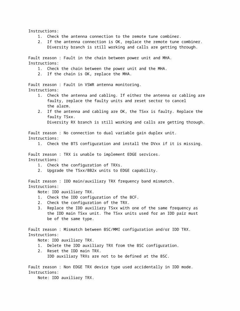
ULTRASITE and CONNECTSITE 100:Fault reason : The reflected power of remote tune combiner is too high.Instructions: 1. Check the antenna connection to the remote tune combiner. 2. If the antenna connection is OK, replace the remote tune combiner. Diversity branch is still working and calls are getting through.
Fault reason : Fault in the chain between power unit and MHA.Instructions: 1. Check the chain between the power unit and the MHA. 2. If the chain is OK, replace the MHA.
Fault reason : Fault in VSWR antenna monitoring.Instructions: 1. Check the antenna and cabling. If either the antenna or cabling are faulty, replace the faulty units and reset sector to cancel the alarm. 2. If the antenna and cabling are OK, the TSxx is faulty. Replace the faulty TSxx. Diversity RX branch is still working and calls are getting through.
Fault reason : No connection to dual variable gain duplex unit.Instructions: 1. Check the BTS configuration and install the DVxx if it is missing.
Fault reason : TRX is unable to implement EDGE services.Instructions: 1. Check the configuration of TRXs. 2. Upgrade the TSxx/BB2x units to EDGE capability.
Fault reason : IDD main/auxiliary TRX frequency band mismatch.Instructions: Note: IDD auxiliary TRX. 1. Check the IDD configuration of the BCF. 2. Check the configuration of the TRX. 3. Replace the IDD auxiliary TSxx with one of the same frequency as the IDD main TSxx unit. The TSxx units used for an IDD pair must be of the same type.
Fault reason : Mismatch between BSC/MMI configuration and/or IDD TRX.Instructions: Note: IDD auxiliary TRX. 1. Delete the IDD auxiliary TRX from the BSC configuration. 2. Reset the IDD main TRX. IDD auxiliary TRXs are not to be defined at the BSC.
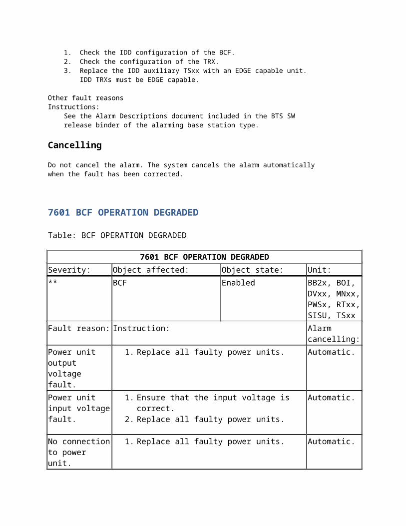
Fault reason : Non EDGE TRX device type used accidentally in IDD mode.Instructions: Note: IDD auxiliary TRX. 1. Check the IDD configuration of the BCF. 2. Check the configuration of the TRX. 3. Replace the IDD auxiliary TSxx with an EDGE capable unit. IDD TRXs must be EDGE capable.
Other fault reasonsInstructions: See the Alarm Descriptions document included in the BTS SW release binder of the alarming base station type.
Cancelling
Do not cancel the alarm. The system cancels the alarm automaticallywhen the fault has been corrected.
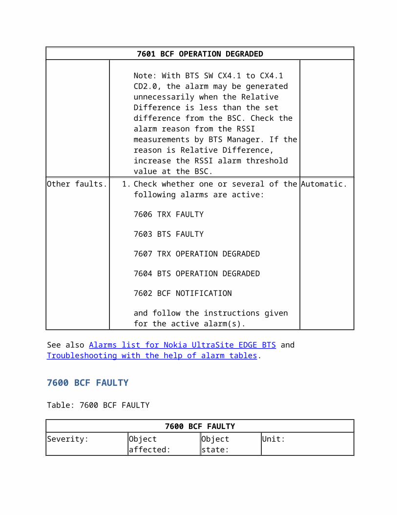
7601 BCF OPERATION DEGRADED
Table: BCF OPERATION DEGRADED
7601 BCF OPERATION DEGRADED
Severity: Object affected: Object state: Unit:
** BCF Enabled BB2x, BOI, DVxx, MNxx, PWSx, RTxx, SISU, TSxx
Fault reason: Instruction: Alarm cancelling:
Power unit output voltage fault.
1. Replace all faulty power units. Automatic.
Power unit input voltage fault.
1. Ensure that the input voltage is correct.2. Replace all faulty power units.
Automatic.
No connection to power unit.
1. Replace all faulty power units. Automatic.
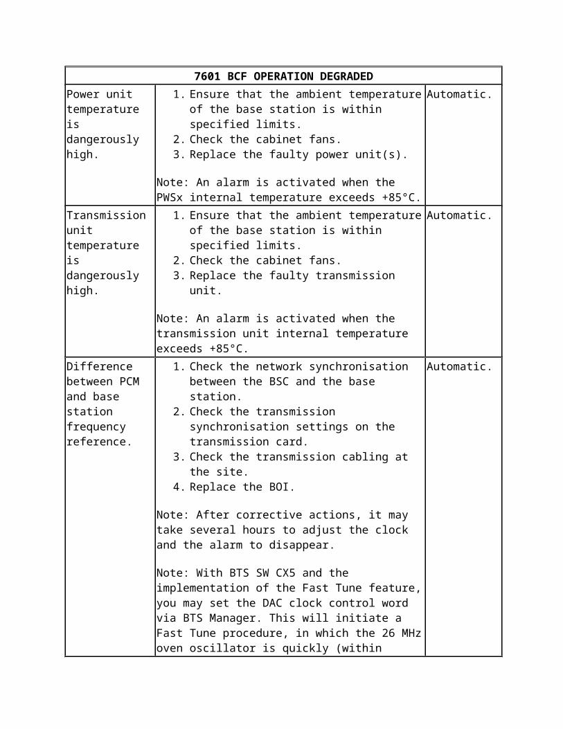
Power unit temperature is dangerously high.
1. Ensure that the ambient temperature of the base station is within specified limits.
2. Check the cabinet fans.3. Replace the faulty power unit(s).
Note: An alarm is activated when the PWSx internal temperature exceeds +85°C.
Automatic.
Transmission unit temperature is dangerously high.
1. Ensure that the ambient temperature of the base station is within specified limits.
2. Check the cabinet fans.3. Replace the faulty transmission unit.
Note: An alarm is activated when the transmission unit internal temperature exceeds +85°C.
Automatic.
Difference between PCM and base station frequency reference.
1. Check the network synchronisation between the BSC and the base station.
2. Check the transmission synchronisation settings on the transmission card.
3. Check the transmission cabling at the site.4. Replace the BOI.
Note: After corrective actions, it may take several hours to adjust the clock and the alarm to disappear.
Note: With BTS SW CX5 and the implementation of the
Automatic.
7601 BCF OPERATION DEGRADED
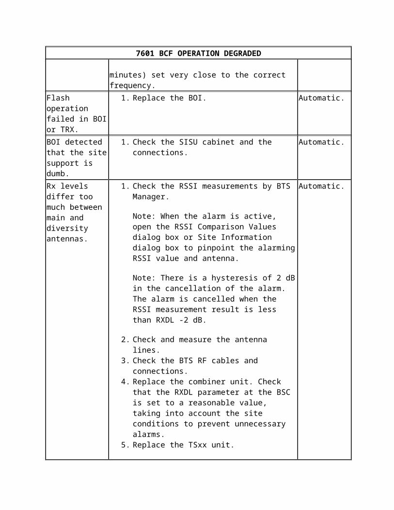
Fast Tune feature, you may set the DAC clock control word via BTS Manager. This will initiate a Fast Tune procedure, in which the 26 MHz oven oscillator is quickly (within minutes) set very close to the correct frequency.
Flash operation failed in BOI or TRX.
1. Replace the BOI. Automatic.
BOI detected that the site support is dumb.
1. Check the SISU cabinet and the connections. Automatic.
Rx levels differ too much between main and diversity antennas.
1. Check the RSSI measurements by BTS Manager.
Note: When the alarm is active, open the RSSI Comparison Values dialog box or Site Information dialog box to pinpoint the alarming RSSI value and antenna.
Note: There is a hysteresis of 2 dB in the cancellation of the alarm. The alarm is cancelled when the RSSI measurement result is less than RXDL -2 dB.
2. Check and measure the antenna lines. 3. Check the BTS RF cables and connections. 4. Replace the combiner unit. Check that the RXDL
parameter at the BSC is set to a reasonable value, taking into account the site conditions to prevent unnecessary alarms.
5. Replace the TSxx unit.
Note: With BTS SW CX4.1 to CX4.1 CD2.0, the alarm may be generated unnecessarily when the Relative Difference is less than the set difference from the BSC. Check the alarm reason from the RSSI measurements by BTS Manager. If the reason is Relative Difference, increase the RSSI alarm threshold value at the BSC.
Automatic.
Other faults. 1. Check whether one or several of the following alarms are active:
7606 TRX FAULTY
Automatic.
7601 BCF OPERATION DEGRADED
7603 BTS FAULTY
7607 TRX OPERATION DEGRADED
7604 BTS OPERATION DEGRADED
7602 BCF NOTIFICATION
and follow the instructions given for the active alarm(s).
See also Alarms list for Nokia UltraSite EDGE BTS and Troubleshooting with the help of alarm tables.
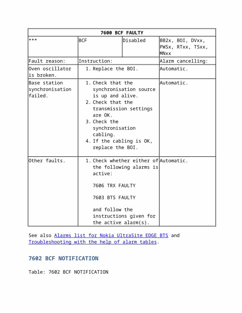
7600 BCF FAULTY
Table: 7600 BCF FAULTY
7600 BCF FAULTY
Severity: Object affected: Object state: Unit:
*** BCF Disabled BB2x, BOI, DVxx, PWSx, RTxx, TSxx, MNxx
Fault reason: Instruction: Alarm cancelling:
Oven oscillator is broken. 1. Replace the BOI. Automatic.
Base station synchronisation failed.
1. Check that the synchronisation source is up and alive.
2. Check that the transmission settings are OK.
3. Check the synchronisation cabling.
4. If the cabling is OK, replace the BOI.
Automatic.
Other faults. 1. Check whether either of the following alarms is active:
7606 TRX FAULTY
7603 BTS FAULTY
Automatic.
7600 BCF FAULTY
and follow the instructions given for the active alarm(s).
See also Alarms list for Nokia UltraSite EDGE BTS and Troubleshooting with the help of alarm tables.
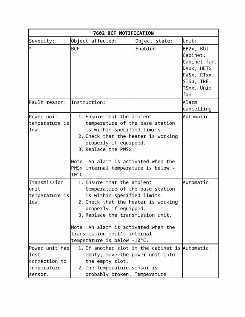
7602 BCF NOTIFICATION
Table: 7602 BCF NOTIFICATION
7602 BCF NOTIFICATION
Severity: Object affected: Object state: Unit:
* BCF Enabled BB2x, BOI, Cabinet, Cabinet fan, DVxx, HETx, PWSx, RTxx, SISU, TRE, TSxx, Unit fan
Fault reason: Instruction: Alarm cancelling:
Power unit temperature is low.
1. Ensure that the ambient temperature of the base station is within specified limits.
2. Check that the heater is working properly if equipped.
3. Replace the PWSx.
Note: An alarm is activated when the PWSx internal temperature is below -10°C.
Automatic.
Transmission unit temperature is low.
1. Ensure that the ambient temperature of the base station is within specified limits.
2. Check that the heater is working properly if equipped.
3. Replace the transmission unit.
Note: An alarm is activated when the transmission unit's internal temperature is below -10°C.
Automatic.
Power unit has lost connection to temperature sensor.
1. If another slot in the cabinet is empty, move the power unit into the empty slot.
2. The temperature sensor is probably broken. Temperature changes cannot be measured.
Automatic.
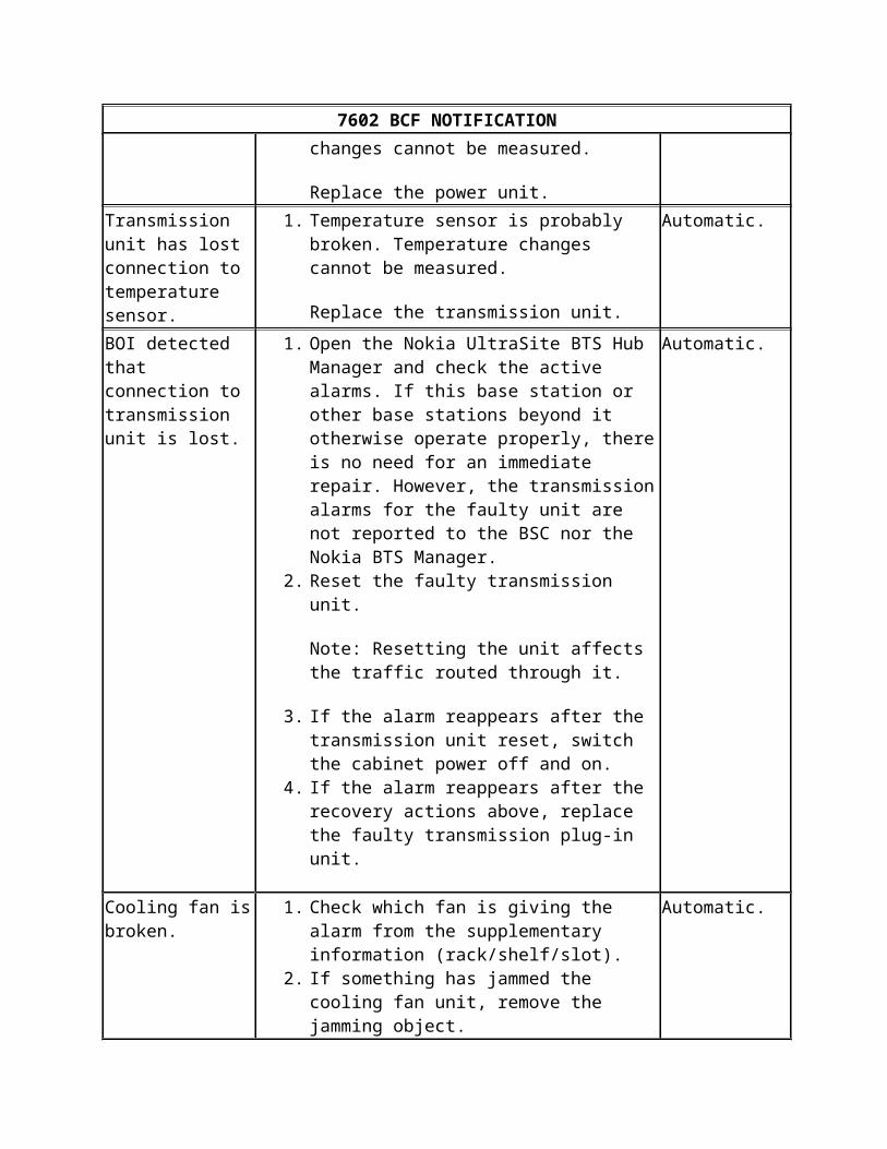
7602 BCF NOTIFICATION
Replace the power unit.
Transmission unit has lost connection to temperature sensor.
1. Temperature sensor is probably broken. Temperature changes cannot be measured.
Replace the transmission unit.
Automatic.
BOI detected that connection to transmission unit is lost.
1. Open the Nokia UltraSite BTS Hub Manager and check the active alarms. If this base station or other base stations beyond it otherwise operate properly, there is no need for an immediate repair. However, the transmission alarms for the faulty unit are not reported to the BSC nor the Nokia BTS Manager.
2. Reset the faulty transmission unit.
Note: Resetting the unit affects the traffic routed through it.
3. If the alarm reappears after the transmission unit reset, switch the cabinet power off and on.
4. If the alarm reappears after the recovery actions above, replace the faulty transmission plug-in unit.
Automatic.
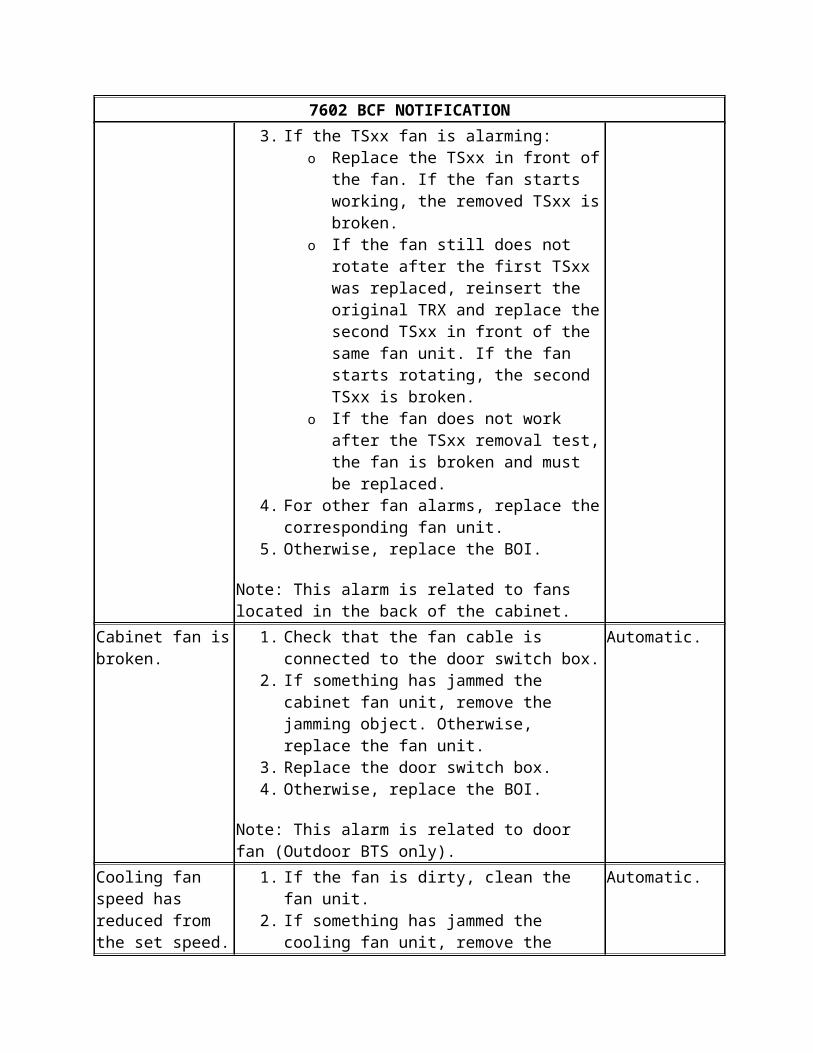
Cooling fan is broken.
1. Check which fan is giving the alarm from the supplementary information (rack/shelf/slot).
2. If something has jammed the cooling fan unit, remove the jamming object.
3. If the TSxx fan is alarming: o Replace the TSxx in front of the fan. If
the fan starts working, the removed TSxx is broken.
o If the fan still does not rotate after the first TSxx was replaced, reinsert the original TRX and replace the second TSxx in front of the same fan unit. If the fan starts rotating, the second TSxx is broken.
o If the fan does not work after the TSxx removal test, the fan is broken and must be replaced.
4. For other fan alarms, replace the corresponding fan unit.
5. Otherwise, replace the BOI.
Automatic.
7602 BCF NOTIFICATION
Note: This alarm is related to fans located in the back of the cabinet.
Cabinet fan is broken.
1. Check that the fan cable is connected to the door switch box.
2. If something has jammed the cabinet fan unit, remove the jamming object. Otherwise, replace the fan unit.
3. Replace the door switch box.4. Otherwise, replace the BOI.
Note: This alarm is related to door fan (Outdoor BTS only).
Automatic.
Cooling fan speed has reduced from the set speed.
1. If the fan is dirty, clean the fan unit.2. If something has jammed the cooling fan unit,
remove the jamming object. Otherwise, replace the fan unit.
Note: This alarm is related to fans located in the back of the cabinet.
Automatic.
Cabinet fan speed has reduced from the set speed.
1. If the fan is dirty, clean the fan unit.2. If something has jammed the cabinet fan unit,
remove the jamming object. Otherwise, replace the fan unit.
Note: This alarm is related to door fan.
Automatic.
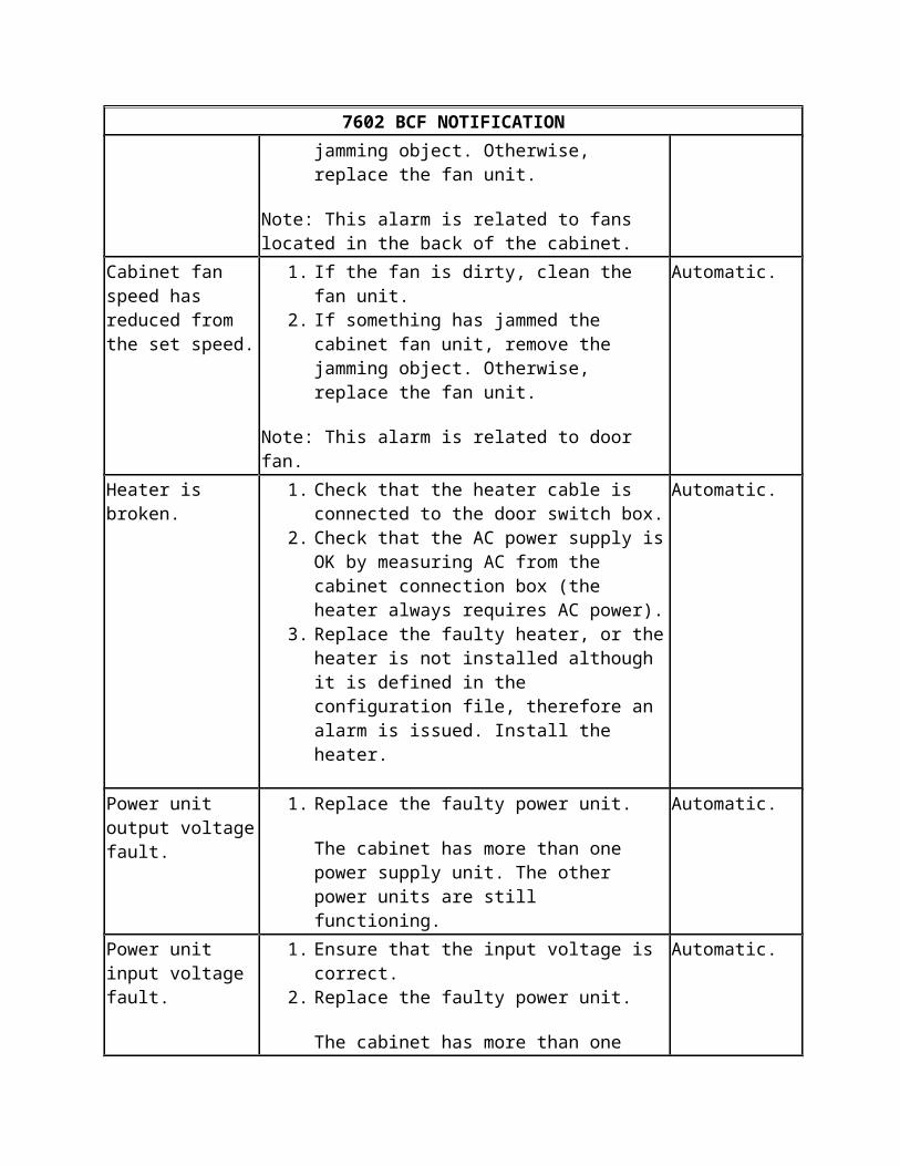
Heater is broken. 1. Check that the heater cable is connected to the door switch box.
2. Check that the AC power supply is OK by measuring AC from the cabinet connection box (the heater always requires AC power).
3. Replace the faulty heater, or the heater is not installed although it is defined in the configuration file, therefore an alarm is issued. Install the heater.
Automatic.
Power unit output voltage fault.
1. Replace the faulty power unit.
The cabinet has more than one power supply unit. The other power units are still functioning.
Automatic.
Power unit input voltage fault.
1. Ensure that the input voltage is correct.2. Replace the faulty power unit.
Automatic.
7602 BCF NOTIFICATION
The cabinet has more than one power supply unit. The other power units are still functioning.
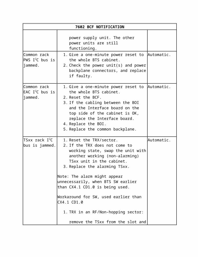
Common rack PWS I2C bus is jammed.
1. Give a one-minute power reset to the whole BTS cabinet.
2. Check the power unit(s) and power backplane connectors, and replace if faulty.
Automatic.
Common rack EAC I2C bus is jammed.
1. Give a one-minute power reset to the whole BTS cabinet.
2. Reset the BCF.3. If the cabling between the BOI and the Interface
board on the top side of the cabinet is OK, replace the Interface board.
4. Replace the BOI.5. Replace the common backplane.
Automatic.
TSxx rack I2C bus is jammed.
1. Reset the TRX/sector.2. If the TRX does not come to working state, swap
the unit with another working (non-alarming) TSxx unit in the cabinet.
3. Replace the alarming TSxx.
Note: The alarm might appear unnecessarily, when BTS SW earlier than CX4.1 CD1.0 is being used.
Workaround for SW, used earlier than CX4.1 CD1.0
1. TRX in an RF/Non-hopping sector:
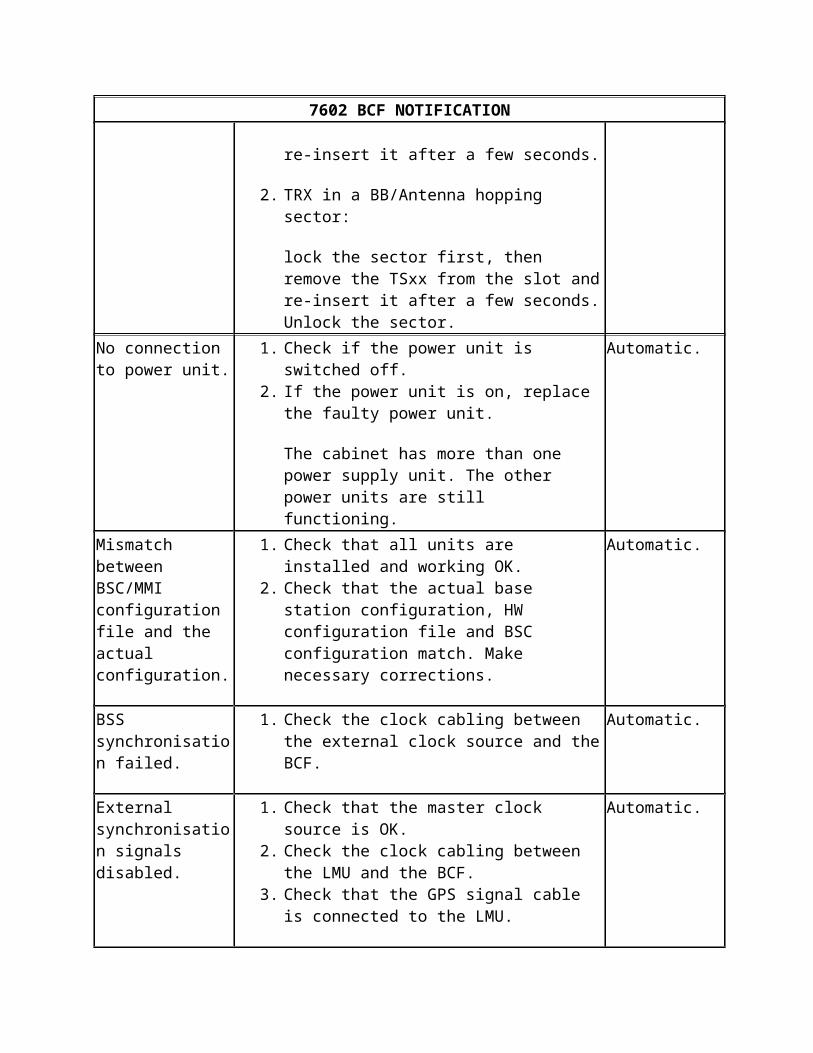
remove the TSxx from the slot and re-insert it after a few seconds.
2. TRX in a BB/Antenna hopping sector:
lock the sector first, then remove the TSxx from the slot and re-insert it after a few seconds. Unlock the sector.
Automatic.
No connection to power unit.
1. Check if the power unit is switched off.2. If the power unit is on, replace the faulty power
unit.
The cabinet has more than one power supply unit. The other power units are still functioning.
Automatic.
7602 BCF NOTIFICATION
Mismatch between BSC/MMI configuration file and the actual configuration.
1. Check that all units are installed and working OK.
2. Check that the actual base station configuration, HW configuration file and BSC configuration match. Make necessary corrections.
Automatic.
BSS synchronisation failed.
1. Check the clock cabling between the external clock source and the BCF.
Automatic.
External synchronisation signals disabled.
1. Check that the master clock source is OK.2. Check the clock cabling between the LMU and
the BCF.3. Check that the GPS signal cable is connected to
the LMU.
Automatic.
See also Alarms list for Nokia UltraSite EDGE BTS and Troubleshooting with the help of alarm tables.
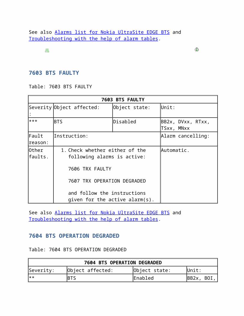
7603 BTS FAULTY
Table: 7603 BTS FAULTY
7603 BTS FAULTY
Severity: Object affected: Object state: Unit:
*** BTS Disabled BB2x, DVxx, RTxx, TSxx, MNxx
Fault reason:
Instruction: Alarm cancelling:
Other faults. 1. Check whether either of the following alarms is active:
7606 TRX FAULTY
7607 TRX OPERATION DEGRADED
and follow the instructions given for the active alarm(s).
Automatic.
See also Alarms list for Nokia UltraSite EDGE BTS and Troubleshooting with the help of alarm tables.
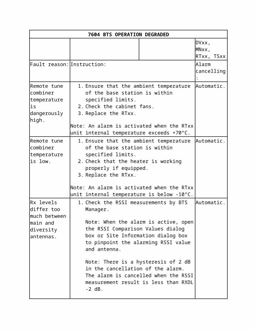
7604 BTS OPERATION DEGRADED
Table: 7604 BTS OPERATION DEGRADED
7604 BTS OPERATION DEGRADED
Severity: Object affected: Object state: Unit:
** BTS Enabled BB2x, BOI, DVxx, MNxx, RTxx, TSxx
Fault reason: Instruction: Alarm cancelling:
Remote tune combiner temperature is dangerously high.
1. Ensure that the ambient temperature of the base station is within specified limits.
2. Check the cabinet fans.3. Replace the RTxx.
Note: An alarm is activated when the RTxx unit internal temperature exceeds +70°C.
Automatic.
Remote tune combiner temperature is low.
1. Ensure that the ambient temperature of the base station is within specified limits.
2. Check that the heater is working properly if equipped.3. Replace the RTxx.
Note: An alarm is activated when the RTxx unit internal temperature is below -10°C.
Automatic.
Rx levels differ too much between main and diversity antennas.
1. Check the RSSI measurements by BTS Manager.
Note: When the alarm is active, open the RSSI Comparison Values dialog box or Site Information dialog box to pinpoint the alarming RSSI value and antenna.
Note: There is a hysteresis of 2 dB in the cancellation of the alarm. The alarm is cancelled when the RSSI measurement result is less than RXDL -2 dB.
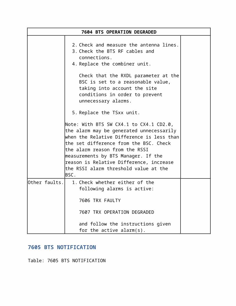
2. Check and measure the antenna lines.3. Check the BTS RF cables and connections.4. Replace the combiner unit.
Check that the RXDL parameter at the BSC is set to a
Automatic.
7604 BTS OPERATION DEGRADED
reasonable value, taking into account the site conditions in order to prevent unnecessary alarms.
5. Replace the TSxx unit.
Note: With BTS SW CX4.1 to CX4.1 CD2.0, the alarm may be generated unnecessarily when the Relative Difference is less than the set difference from the BSC. Check the alarm reason from the RSSI measurements by BTS Manager. If the reason is Relative Difference, increase the RSSI alarm threshold value at the BSC.
Other faults. 1. Check whether either of the following alarms is active:
7606 TRX FAULTY
7607 TRX OPERATION DEGRADED
and follow the instructions given for the active alarm(s).
7605 BTS NOTIFICATION
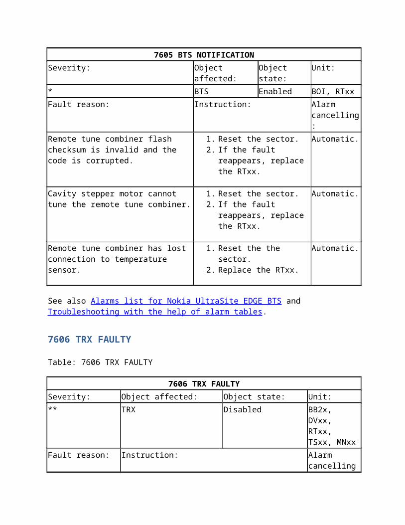
Table: 7605 BTS NOTIFICATION
7605 BTS NOTIFICATION
Severity: Object affected: Object state: Unit:
* BTS Enabled BOI, RTxx
Fault reason: Instruction: Alarm cancelling:
Remote tune combiner flash checksum is invalid and the code is corrupted.
1. Reset the sector.2. If the fault reappears,
replace the RTxx.
Automatic.
Cavity stepper motor cannot tune the remote tune combiner.
1. Reset the sector.2. If the fault reappears,
replace the RTxx.
Automatic.
Remote tune combiner has lost connection to temperature sensor.
1. Reset the the sector.2. Replace the RTxx.
Automatic.
See also Alarms list for Nokia UltraSite EDGE BTS and Troubleshooting with the help of alarm tables.
7606 TRX FAULTY
Table: 7606 TRX FAULTY
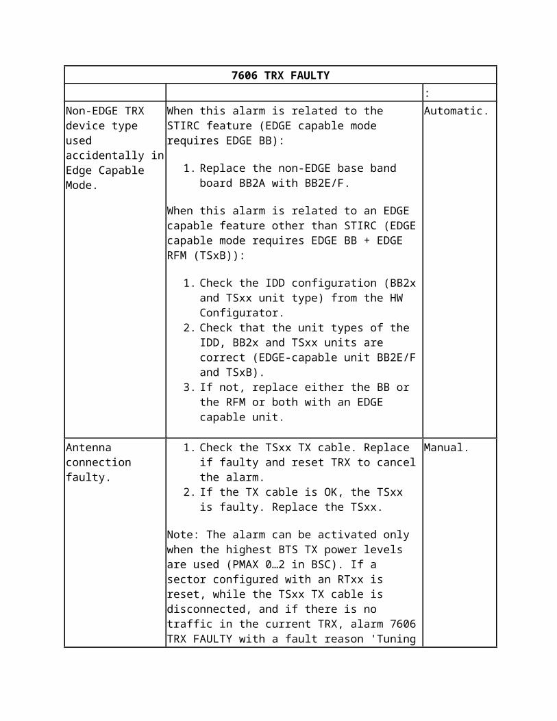
7606 TRX FAULTY
Severity: Object affected: Object state: Unit:
** TRX Disabled BB2x, DVxx, RTxx, TSxx, MNxx
Fault reason: Instruction: Alarm cancelling:
Non-EDGE TRX device type used accidentally in Edge Capable Mode.
When this alarm is related to the STIRC feature (EDGE capable mode requires EDGE BB):
1. Replace the non-EDGE base band board BB2A with BB2E/F.
When this alarm is related to an EDGE capable feature other than STIRC (EDGE capable mode requires EDGE BB + EDGE RFM (TSxB)):
1. Check the IDD configuration (BB2x and TSxx unit type) from the HW Configurator.
2. Check that the unit types of the IDD, BB2x and TSxx units are correct (EDGE-capable unit BB2E/F and TSxB).
3. If not, replace either the BB or the RFM or both with an EDGE capable unit.
Automatic.
Antenna connection faulty.
1. Check the TSxx TX cable. Replace if faulty and reset TRX to cancel the alarm.
2. If the TX cable is OK, the TSxx is faulty. Replace the TSxx.
Note: The alarm can be activated only when the highest BTS TX power levels are used (PMAX 0…2 in BSC). If a sector configured with an RTxx is reset, while the TSxx TX cable is disconnected, and if there is no traffic in the current TRX, alarm 7606 TRX FAULTY with a fault reason 'Tuning carrier is not detected in remote tune combiner' is issued.
Manual.
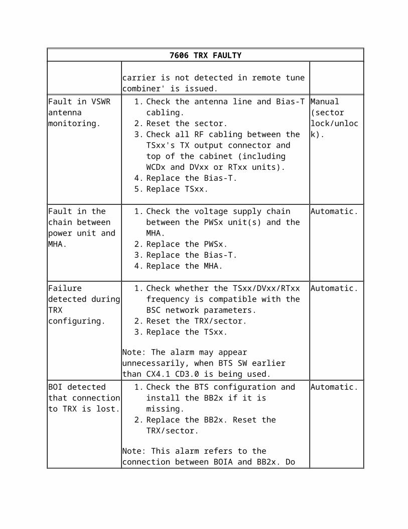
7606 TRX FAULTY
Fault in VSWR antenna monitoring.
1. Check the antenna line and Bias-T cabling.2. Reset the sector.3. Check all RF cabling between the TSxx's TX
output connector and top of the cabinet (including WCDx and DVxx or RTxx units).
4. Replace the Bias-T.5. Replace TSxx.
Manual (sector lock/unlock).
Fault in the chain between power unit and MHA.
1. Check the voltage supply chain between the PWSx unit(s) and the MHA.
2. Replace the PWSx.3. Replace the Bias-T.4. Replace the MHA.
Automatic.
Failure detected during TRX configuring.
1. Check whether the TSxx/DVxx/RTxx frequency is compatible with the BSC network parameters.
2. Reset the TRX/sector.3. Replace the TSxx.
Note: The alarm may appear unnecessarily, when BTS SW earlier than CX4.1 CD3.0 is being used.
Automatic.
BOI detected that connection to TRX is lost.
1. Check the BTS configuration and install the BB2x if it is missing.
2. Replace the BB2x. Reset the TRX/sector.
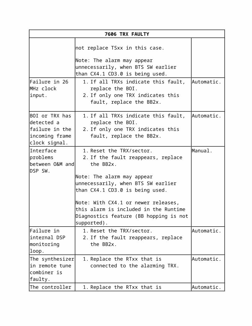
Note: This alarm refers to the connection between BOIA and BB2x. Do not replace TSxx in this case.
Note: The alarm may appear unnecessarily, when BTS SW earlier than CX4.1 CD3.0 is being used.
Automatic.
Failure in 26 MHz clock input.
1. If all TRXs indicate this fault, replace the BOI.2. If only one TRX indicates this fault, replace the
BB2x.
Automatic.
BOI or TRX has detected a failure in the incoming frame clock signal.
1. If all TRXs indicate this fault, replace the BOI.2. If only one TRX indicates this fault, replace the
BB2x.
Automatic.
Interface problems between O&M and DSP SW.
1. Reset the TRX/sector.2. If the fault reappears, replace the BB2x.
Note: The alarm may appear unnecessarily, when BTS
Manual.
7606 TRX FAULTY
SW earlier than CX4.1 CD3.0 is being used.
Note: With CX4.1 or newer releases, this alarm is included in the Runtime Diagnostics feature (BB hopping is not supported).
Failure in internal DSP monitoring loop.
1. Reset the TRX/sector.2. If the fault reappears, replace the BB2x.
Automatic.
The synthesizer in remote tune combiner is faulty.
1. Replace the RTxx that is connected to the alarming TRX.
Automatic.
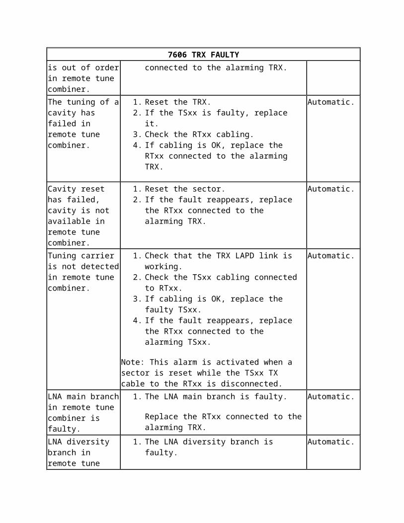
The controller is out of order in remote tune combiner.
1. Replace the RTxx that is connected to the alarming TRX.
Automatic.
The tuning of a cavity has failed in remote tune combiner.
1. Reset the TRX.2. If the TSxx is faulty, replace it.3. Check the RTxx cabling.4. If cabling is OK, replace the RTxx connected to
the alarming TRX.
Automatic.
Cavity reset has failed, cavity is not available in remote tune combiner.
1. Reset the sector.2. If the fault reappears, replace the RTxx connected
to the alarming TRX.
Automatic.
Tuning carrier is not detected in remote tune combiner.
1. Check that the TRX LAPD link is working.2. Check the TSxx cabling connected to RTxx.3. If cabling is OK, replace the faulty TSxx.4. If the fault reappears, replace the RTxx connected
to the alarming TSxx.
Note: This alarm is activated when a sector is reset while the TSxx TX cable to the RTxx is disconnected.
Automatic.
LNA main branch in remote tune combiner is faulty.
1. The LNA main branch is faulty.
Replace the RTxx connected to the alarming TRX.
Automatic.
LNA diversity branch in remote tune combiner is faulty.
1. The LNA diversity branch is faulty.
Replace the RTxx connected to the alarming TRX.
Automatic.
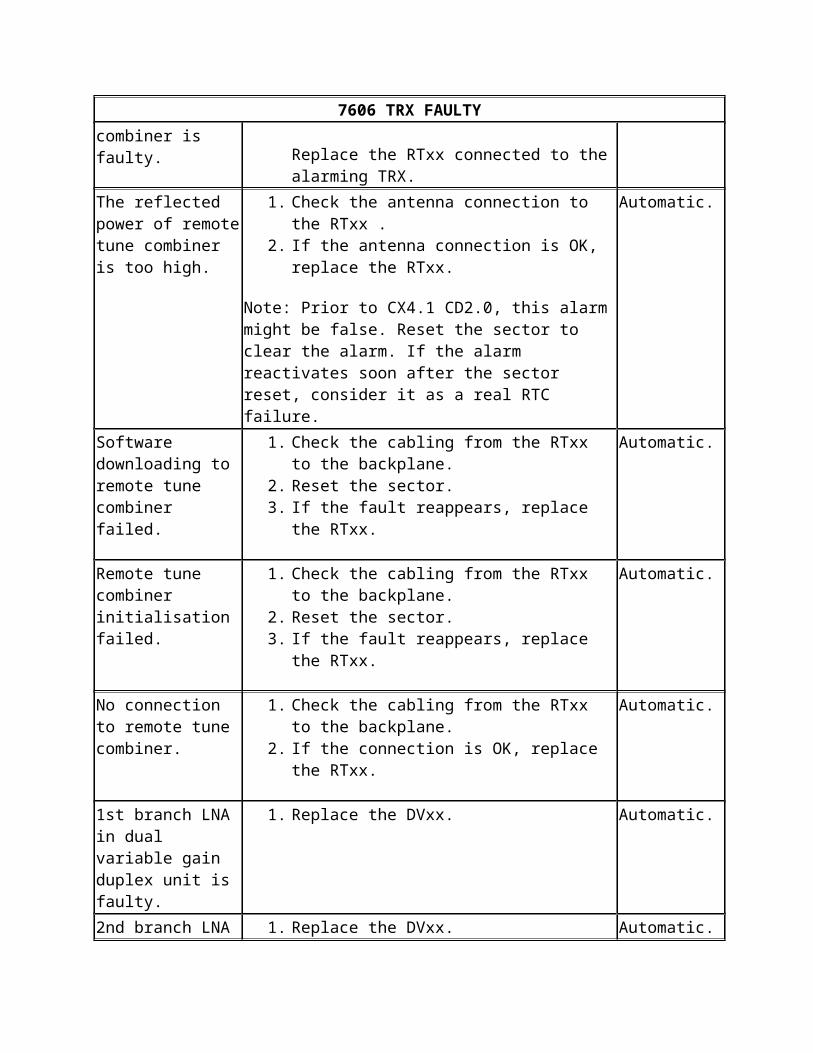
The reflected power of remote tune combiner is too high.
1. Check the antenna connection to the RTxx .2. If the antenna connection is OK, replace the
RTxx.
Automatic.
7606 TRX FAULTY
Note: Prior to CX4.1 CD2.0, this alarm might be false. Reset the sector to clear the alarm. If the alarm reactivates soon after the sector reset, consider it as a real RTC failure.
Software downloading to remote tune combiner failed.
1. Check the cabling from the RTxx to the backplane.
2. Reset the sector.3. If the fault reappears, replace the RTxx.
Automatic.
Remote tune combiner initialisation failed.
1. Check the cabling from the RTxx to the backplane.
2. Reset the sector.3. If the fault reappears, replace the RTxx.
Automatic.
No connection to remote tune combiner.
1. Check the cabling from the RTxx to the backplane.
2. If the connection is OK, replace the RTxx.
Automatic.
1st branch LNA in dual variable gain duplex unit is faulty.
1. Replace the DVxx. Automatic.
2nd branch LNA in dual variable gain duplex unit is faulty.
1. Replace the DVxx. Automatic.
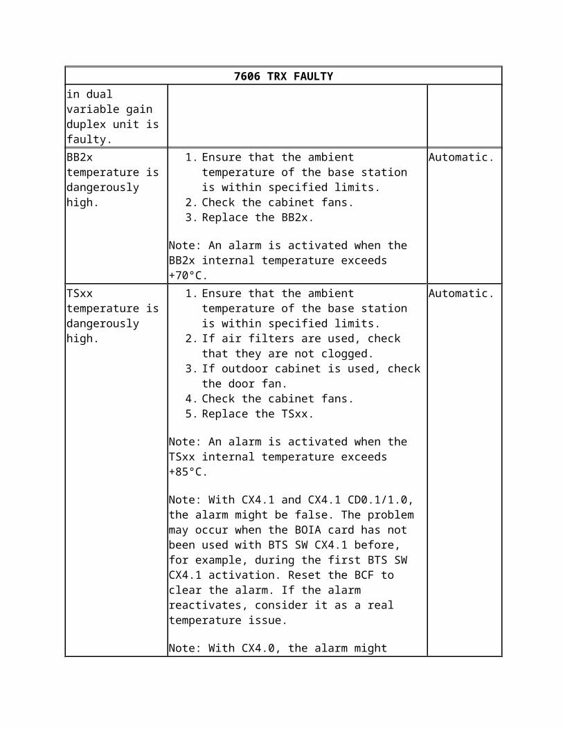
BB2x temperature is dangerously high.
1. Ensure that the ambient temperature of the base station is within specified limits.
2. Check the cabinet fans.3. Replace the BB2x.
Note: An alarm is activated when the BB2x internal temperature exceeds +70°C.
Automatic.
TSxx temperature is dangerously high.
1. Ensure that the ambient temperature of the base station is within specified limits.
2. If air filters are used, check that they are not clogged.
3. If outdoor cabinet is used, check the door fan.4. Check the cabinet fans.5. Replace the TSxx.
Note: An alarm is activated when the TSxx internal temperature exceeds +85°C.
Automatic.
7606 TRX FAULTY
Note: With CX4.1 and CX4.1 CD0.1/1.0, the alarm might be false. The problem may occur when the BOIA card has not been used with BTS SW CX4.1 before, for example, during the first BTS SW CX4.1 activation. Reset the BCF to clear the alarm. If the alarm reactivates, consider it as a real temperature issue.
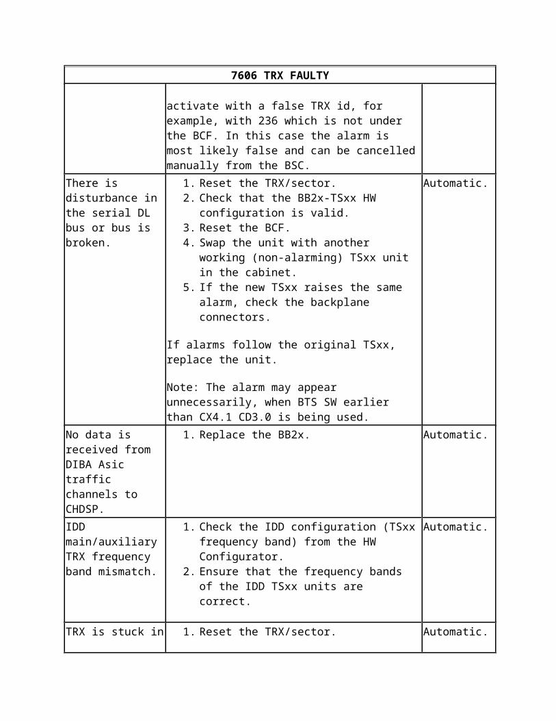
Note: With CX4.0, the alarm might activate with a false TRX id, for example, with 236 which is not under the BCF. In this case the alarm is most likely false and can be cancelled manually from the BSC.
There is disturbance in the serial DL bus or bus is broken.
1. Reset the TRX/sector.2. Check that the BB2x-TSxx HW configuration is
valid.3. Reset the BCF.4. Swap the unit with another working (non-
alarming) TSxx unit in the cabinet.5. If the new TSxx raises the same alarm, check the
backplane connectors.
If alarms follow the original TSxx, replace the unit.
Note: The alarm may appear unnecessarily, when BTS SW earlier than CX4.1 CD3.0 is being used.
Automatic.
No data is received from DIBA Asic traffic channels to CHDSP.
1. Replace the BB2x. Automatic.
IDD main/auxiliary TRX frequency band mismatch.
1. Check the IDD configuration (TSxx frequency band) from the HW Configurator.
2. Ensure that the frequency bands of the IDD TSxx units are correct.
Automatic.
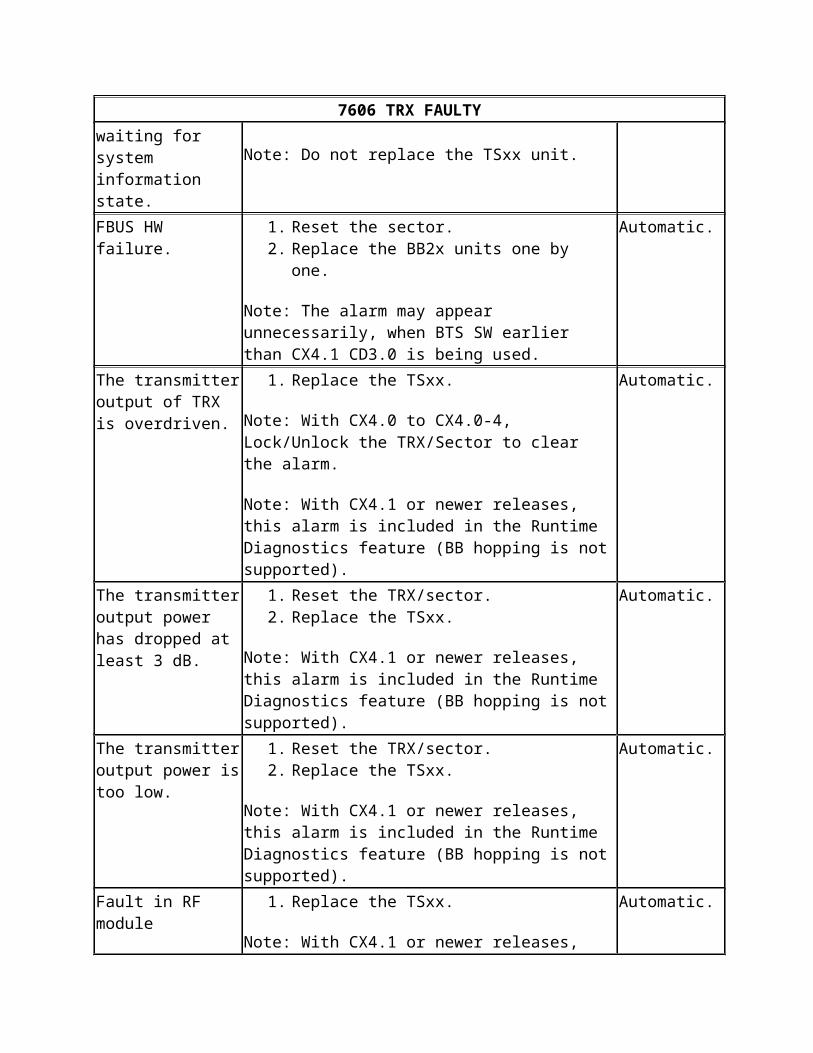
TRX is stuck in waiting for system information state.
1. Reset the TRX/sector.
Note: Do not replace the TSxx unit.
Automatic.
FBUS HW failure. 1. Reset the sector.2. Replace the BB2x units one by one.
Note: The alarm may appear unnecessarily, when BTS SW earlier than CX4.1 CD3.0 is being used.
Automatic.
The transmitter output 1. Replace the TSxx. Automatic.
7606 TRX FAULTY
of TRX is overdriven.
Note: With CX4.0 to CX4.0-4, Lock/Unlock the TRX/Sector to clear the alarm.
Note: With CX4.1 or newer releases, this alarm is included in the Runtime Diagnostics feature (BB hopping is not supported).
The transmitter output power has dropped at least 3 dB.
1. Reset the TRX/sector.2. Replace the TSxx.
Note: With CX4.1 or newer releases, this alarm is included in the Runtime Diagnostics feature (BB hopping is not supported).
Automatic.
The transmitter output power is too low.
1. Reset the TRX/sector.2. Replace the TSxx.
Note: With CX4.1 or newer releases, this alarm is included in the Runtime Diagnostics feature (BB hopping is not supported).
Automatic.
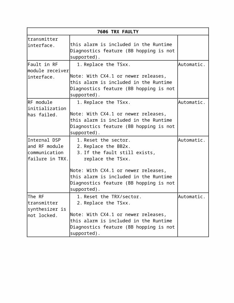
Fault in RF module transmitter interface.
1. Replace the TSxx.
Note: With CX4.1 or newer releases, this alarm is included in the Runtime Diagnostics feature (BB hopping is not supported).
Automatic.
Fault in RF module receiver interface.
1. Replace the TSxx.
Note: With CX4.1 or newer releases, this alarm is included in the Runtime Diagnostics feature (BB hopping is not supported).
Automatic.
RF module initialization has failed.
1. Replace the TSxx.
Note: With CX4.1 or newer releases, this alarm is included in the Runtime Diagnostics feature (BB hopping is not supported).
Automatic.
Internal DSP and RF module communication failure in TRX.
1. Reset the sector.2. Replace the BB2x.3. If the fault still exists, replace the TSxx.
Note: With CX4.1 or newer releases, this alarm is included in the Runtime Diagnostics feature (BB hopping is not supported).
Automatic.
The RF transmitter 1. Reset the TRX/sector. Automatic.
7606 TRX FAULTY
synthesizer is not locked.
2. Replace the TSxx.
Note: With CX4.1 or newer releases, this alarm is included in the Runtime Diagnostics feature (BB hopping is not supported).
The RF transmitter frequency hopping synthesizer 1 is not locked.
1. Reset the TRX/sector.2. Replace the TSxx.
Note: The alarm may appear unnecessarily, when BTS SW earlier than CX4.1 CD3.0 is being used.
Automatic.
The RF transmitter frequency hopping synthesizer 2 is not locked.
1. Reset the TRX/sector.2. Replace the TSxx.
Note: With CX4.1 or newer releases, this alarm is included in the Runtime Diagnostics feature (BB hopping is not supported).
Automatic.
The RF receiver synthesizer is not locked.
1. Reset the TRX/sector.2. Replace the TSxx.
Note: With CX4.1 or newer releases, this alarm is included in the Runtime Diagnostics feature (BB hopping is not supported).
Automatic.
The RF receiver frequency hopping synthesizer 1 is not locked.
1. Reset the TRX/sector.2. Replace the TSxx.
Note: With CX4.1 or newer releases, this alarm is included in the Runtime Diagnostics feature (BB hopping is not supported).
Automatic.
The RF receiver frequency hopping synthesizer 2 is not locked.
1. Reset the TRX/sector.2. Replace the TSxx.
Note: With CX4.1 or newer releases, this alarm is included in the Runtime Diagnostics feature (BB hopping is not supported).
Automatic.
Invalid BB hopping set-up.
1. Not a supported BB configuration. Check the Technical Note No. 34 for supported BB hopping configurations.
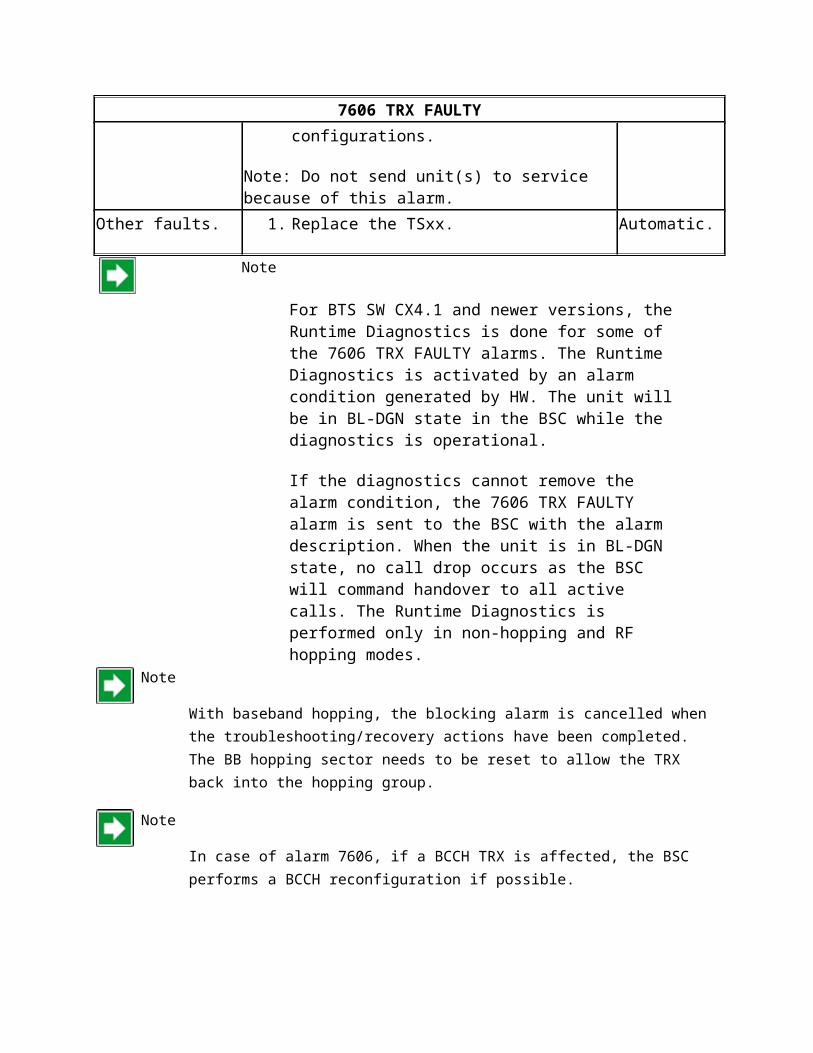
Note: Do not send unit(s) to service because of this alarm.
Manual.
Other faults. 1. Replace the TSxx. Automatic.
7606 TRX FAULTYNote
For BTS SW CX4.1 and newer versions, the Runtime Diagnostics is done for some of the 7606 TRX FAULTY alarms. The Runtime Diagnostics is activated by an alarm condition generated by HW. The unit will be in BL-DGN state in the BSC while the diagnostics is operational.
If the diagnostics cannot remove the alarm condition, the 7606 TRX FAULTY alarm is sent to the BSC with the alarm description. When the unit is in BL-DGN state, no call drop occurs as the BSC will command handover to all active calls. The Runtime Diagnostics is performed only in non-hopping and RF hopping modes.
Note
With baseband hopping, the blocking alarm is cancelled when the troubleshooting/recovery actions have been completed. The BB hopping sector needs to be reset to allow the TRX back into the hopping group.
Note
In case of alarm 7606, if a BCCH TRX is affected, the BSC performs a BCCH reconfiguration if possible.
See also Alarms list for Nokia UltraSite EDGE BTS and Troubleshooting with the help of alarm tables.
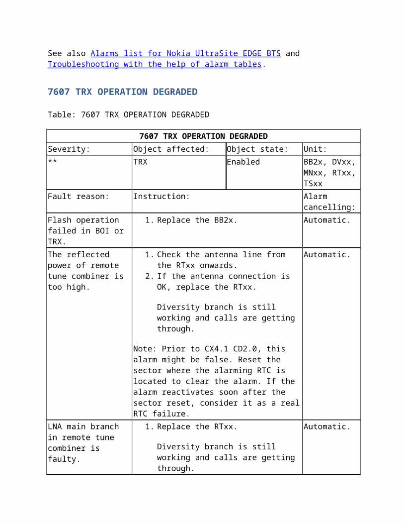
7607 TRX OPERATION DEGRADED
Table: 7607 TRX OPERATION DEGRADED
7607 TRX OPERATION DEGRADED
Severity: Object affected: Object state: Unit:
** TRX Enabled BB2x, DVxx, MNxx, RTxx, TSxx
Fault reason: Instruction: Alarm cancelling:
Flash operation failed in BOI or TRX.
1. Replace the BB2x. Automatic.
7607 TRX OPERATION DEGRADED
The reflected power of remote tune combiner is too high.
1. Check the antenna line from the RTxx onwards.
2. If the antenna connection is OK, replace the RTxx.
Diversity branch is still working and calls are getting through.
Note: Prior to CX4.1 CD2.0, this alarm might be false. Reset the sector where the alarming RTC is located to clear the alarm. If the alarm reactivates soon after the sector reset, consider it as a real RTC failure.
Automatic.
LNA main branch in remote tune combiner is faulty.
1. Replace the RTxx.
Diversity branch is still working and calls are getting through.
Automatic.
LNA diversity branch in remote tune combiner is faulty.
1. Replace the RTxx.
Main branch is still working and calls are getting through.
Automatic.
The synthesizer in remote tune combiner is faulty.
1. Replace the RTxx.
Diversity branch is still working and calls are getting through.
Automatic.
The controller is out of order in remote tune combiner.
1. Replace the RTxx.
Diversity branch is still working and calls are getting through.
Automatic.
Performance of the main branch LNA in remote tune combiner is degraded.
1. Replace the RTxx.
Diversity branch is still working and calls are getting through.
Automatic.
Performance of the diversity branch LNA in remote tune combiner is degraded.
1. Replace the RTxx.
Main branch is still working and calls are getting through.
Automatic.
1st branch LNA in dual variable gain duplex unit is faulty.
1. Replace the DVxx.
2nd branch is still working and calls are getting through.
Automatic.
2nd branch LNA in dual variable gain duplex unit
1. Replace the DVxx. Automatic.
7607 TRX OPERATION DEGRADED
is faulty.1st branch is still working and calls are getting through.
Performance is degraded in the 1st branch dual variable gain unit.
1. Replace the DVxx.
2nd branch is still working and calls are getting through.
Automatic.
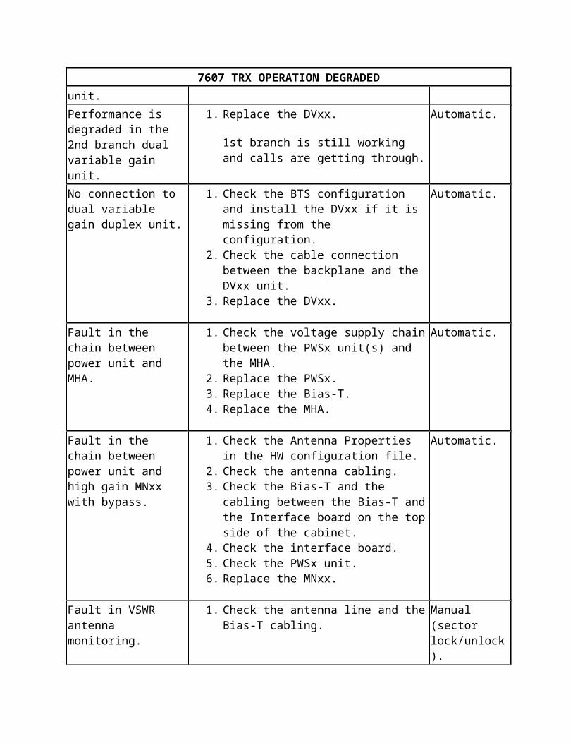
Performance is degraded in the 2nd branch dual variable gain unit.
1. Replace the DVxx.
1st branch is still working and calls are getting through.
Automatic.
No connection to dual variable gain duplex unit.
1. Check the BTS configuration and install the DVxx if it is missing from the configuration.
2. Check the cable connection between the backplane and the DVxx unit.
3. Replace the DVxx.
Automatic.
Fault in the chain between power unit and MHA.
1. Check the voltage supply chain between the PWSx unit(s) and the MHA.
2. Replace the PWSx.3. Replace the Bias-T.4. Replace the MHA.
Automatic.
Fault in the chain between power unit and high gain MNxx with bypass.
1. Check the Antenna Properties in the HW configuration file.
2. Check the antenna cabling.3. Check the Bias-T and the cabling between
the Bias-T and the Interface board on the top side of the cabinet.
4. Check the interface board.5. Check the PWSx unit.6. Replace the MNxx.
Automatic.
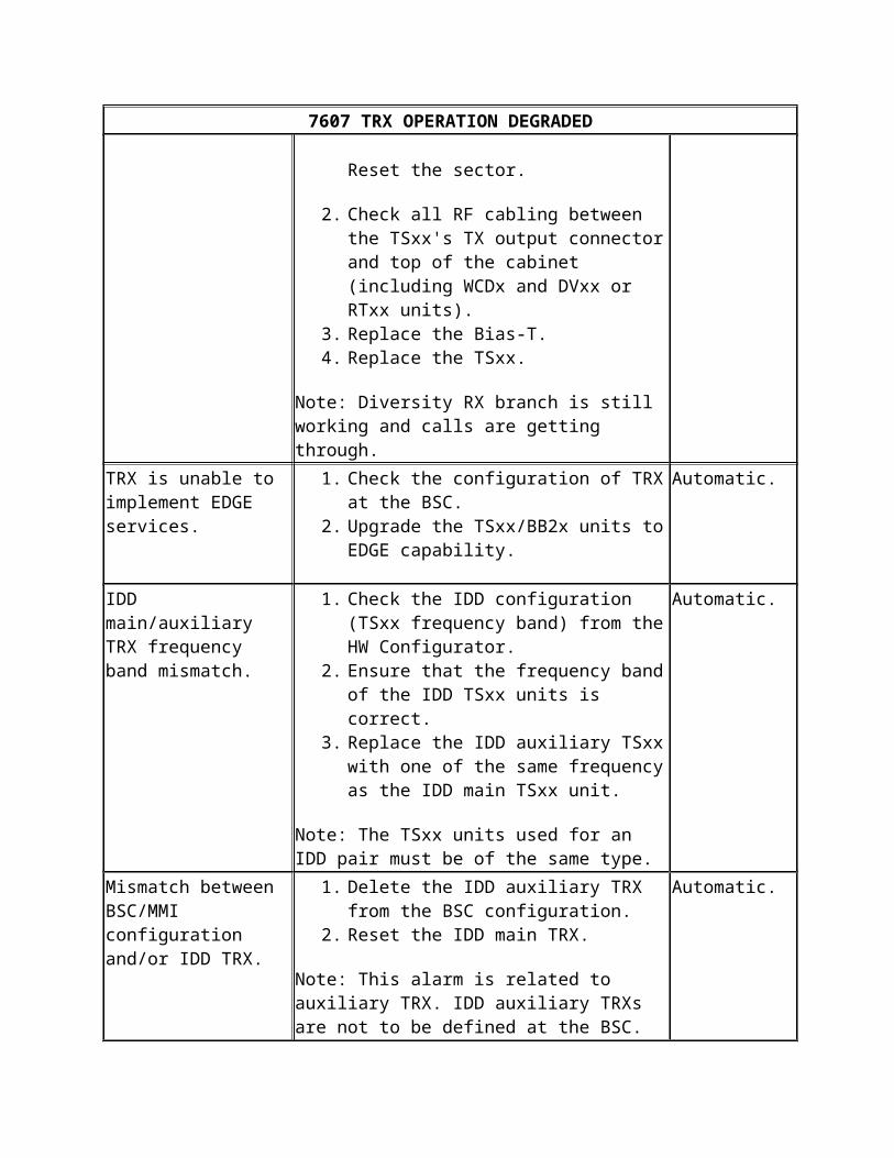
Fault in VSWR antenna monitoring.
1. Check the antenna line and the Bias-T cabling.
Reset the sector.
2. Check all RF cabling between the TSxx's TX output connector and top of the cabinet (including WCDx and DVxx or RTxx units).
3. Replace the Bias-T.
Manual (sector lock/unlock).
7607 TRX OPERATION DEGRADED
4. Replace the TSxx.
Note: Diversity RX branch is still working and calls are getting through.
TRX is unable to implement EDGE services.
1. Check the configuration of TRX at the BSC.2. Upgrade the TSxx/BB2x units to EDGE
capability.
Automatic.
IDD main/auxiliary TRX frequency band mismatch.
1. Check the IDD configuration (TSxx frequency band) from the HW Configurator.
2. Ensure that the frequency band of the IDD TSxx units is correct.
3. Replace the IDD auxiliary TSxx with one of the same frequency as the IDD main TSxx unit.
Note: The TSxx units used for an IDD pair must be of the same type.
Automatic.
Mismatch between BSC/MMI configuration and/or IDD TRX.
1. Delete the IDD auxiliary TRX from the BSC configuration.
2. Reset the IDD main TRX.
Note: This alarm is related to auxiliary TRX. IDD auxiliary TRXs are not to be defined at the BSC.
Automatic.
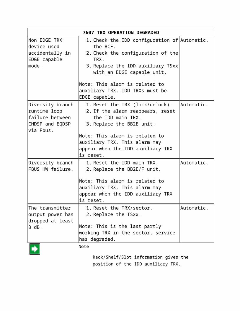
Non EDGE TRX device used accidentally in EDGE capable mode.
1. Check the IDD configuration of the BCF.2. Check the configuration of the TRX.3. Replace the IDD auxiliary TSxx with an
EDGE capable unit.
Note: This alarm is related to auxiliary TRX. IDD TRXs must be EDGE capable.
Automatic.
Diversity branch runtime loop failure between CHDSP and EQDSP via Fbus.
1. Reset the TRX (lock/unlock).2. If the alarm reappears, reset the IDD main
TRX.3. Replace the BB2E unit.
Note: This alarm is related to auxiliary TRX. This alarm may appear when the IDD auxiliary TRX is reset.
Automatic.
Diversity branch FBUS HW failure.
1. Reset the IDD main TRX.2. Replace the BB2E/F unit.
Note: This alarm is related to auxiliary TRX. This
Automatic.
7607 TRX OPERATION DEGRADED
alarm may appear when the IDD auxiliary TRX is reset.
The transmitter output power has dropped at least 3 dB.
1. Reset the TRX/sector.2. Replace the TSxx.
Note: This is the last partly working TRX in the sector, service has degraded.
Automatic.
Note
Rack/Shelf/Slot information gives the position of the IDD auxiliary TRX.
See also Alarms list for Nokia UltraSite EDGE BTS and Troubleshooting with the help of alarm tables.
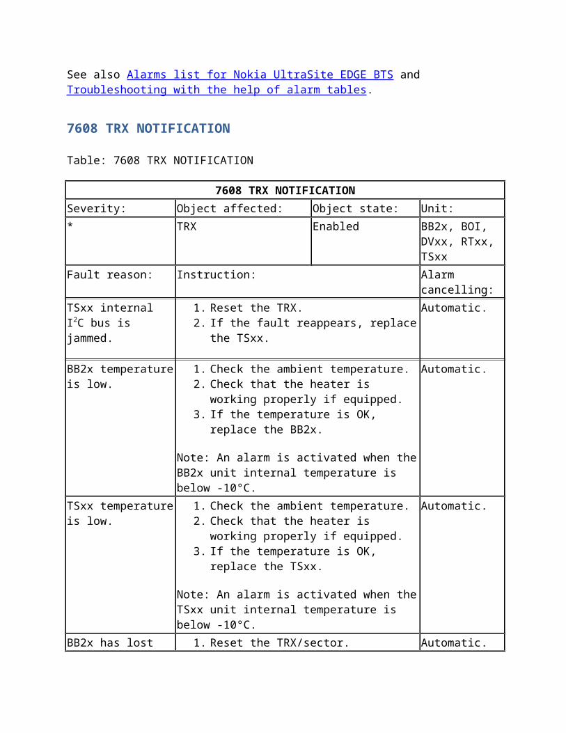
7608 TRX NOTIFICATION
Table: 7608 TRX NOTIFICATION
7608 TRX NOTIFICATION
Severity: Object affected: Object state: Unit:
* TRX Enabled BB2x, BOI, DVxx, RTxx, TSxx
Fault reason: Instruction: Alarm cancelling:
TSxx internal I2C bus is jammed.
1. Reset the TRX.2. If the fault reappears, replace the TSxx.
Automatic.
BB2x temperature is low.
1. Check the ambient temperature.2. Check that the heater is working properly if
equipped.3. If the temperature is OK, replace the BB2x.
Note: An alarm is activated when the BB2x unit internal temperature is below -10°C.
Automatic.
TSxx temperature is low.
1. Check the ambient temperature.2. Check that the heater is working properly if
equipped.3. If the temperature is OK, replace the TSxx.
Automatic.
7608 TRX NOTIFICATION
Note: An alarm is activated when the TSxx unit internal temperature is below -10°C.
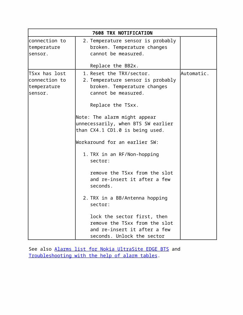
BB2x has lost connection to temperature sensor.
1. Reset the TRX/sector.2. Temperature sensor is probably broken.
Temperature changes cannot be measured.
Replace the BB2x.
Automatic.
TSxx has lost connection to temperature sensor.
1. Reset the TRX/sector.2. Temperature sensor is probably broken.
Temperature changes cannot be measured.
Replace the TSxx.
Note: The alarm might appear unnecessarily, when BTS SW earlier than CX4.1 CD1.0 is being used.
Workaround for an earlier SW:
1. TRX in an RF/Non-hopping sector:
remove the TSxx from the slot and re-insert it after a few seconds.
2. TRX in a BB/Antenna hopping sector:
lock the sector first, then remove the TSxx from the slot and re-insert it after a few seconds. Unlock the sector
Automatic.
See also Alarms list for Nokia UltraSite EDGE BTS and Troubleshooting with the help of alarm tables.
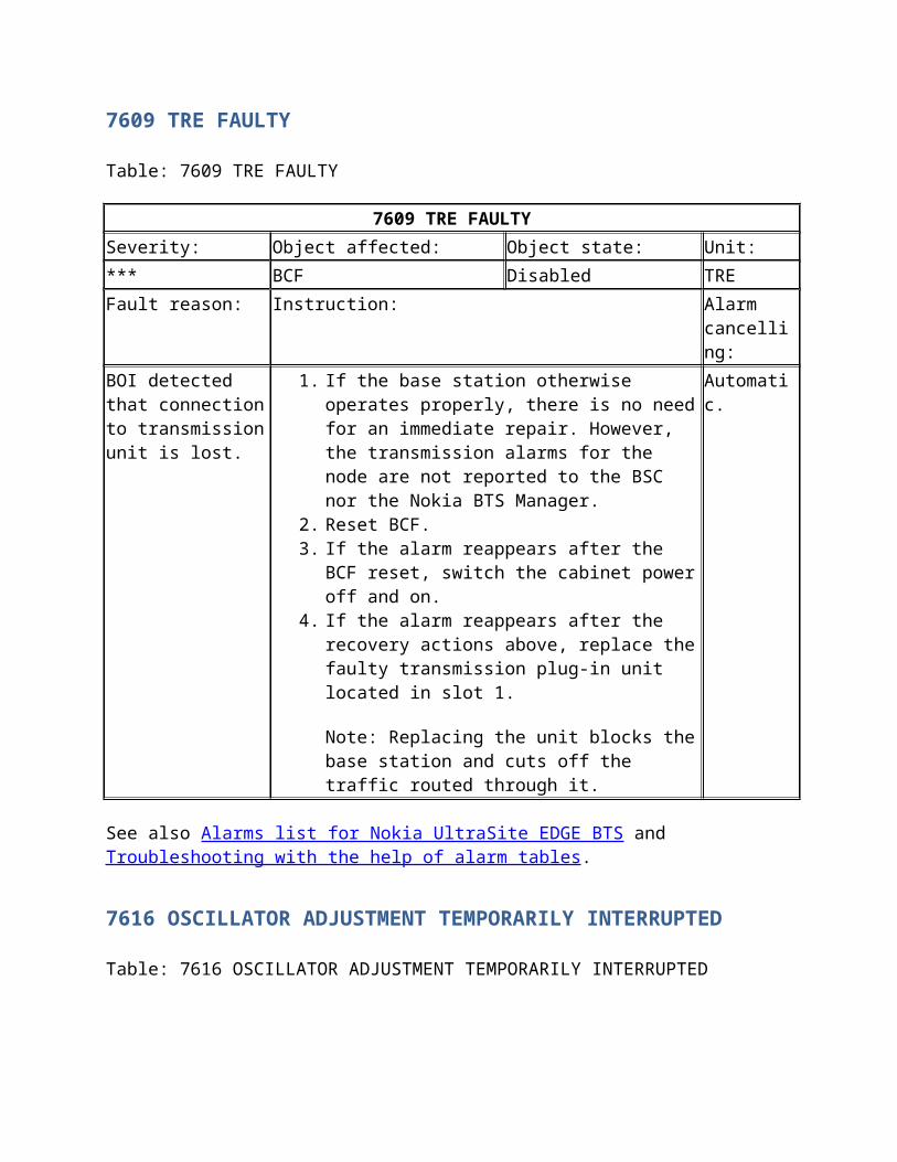
7609 TRE FAULTY
Table: 7609 TRE FAULTY
7609 TRE FAULTY
Severity: Object affected: Object state: Unit:
*** BCF Disabled TRE
Fault reason: Instruction: Alarm cancelling:
7609 TRE FAULTY
BOI detected that connection to transmission unit is lost.
1. If the base station otherwise operates properly, there is no need for an immediate repair. However, the transmission alarms for the node are not reported to the BSC nor the Nokia BTS Manager.
2. Reset BCF.3. If the alarm reappears after the BCF reset, switch the
cabinet power off and on.4. If the alarm reappears after the recovery actions
above, replace the faulty transmission plug-in unit located in slot 1.
Note: Replacing the unit blocks the base station and cuts off the traffic routed through it.
Automatic.
See also Alarms list for Nokia UltraSite EDGE BTS and Troubleshooting with the help of alarm tables.
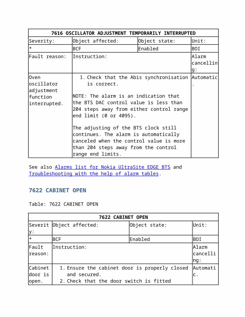
7616 OSCILLATOR ADJUSTMENT TEMPORARILY INTERRUPTED
Table: 7616 OSCILLATOR ADJUSTMENT TEMPORARILY INTERRUPTED
7616 OSCILLATOR ADJUSTMENT TEMPORARILY INTERRUPTED
Severity: Object affected: Object state: Unit:
* BCF Enabled BOI
Fault reason: Instruction: Alarm cancelling:
Oven oscillator adjustment function interrupted.
1. Check that the Abis synchronisation is correct.
NOTE: The alarm is an indication that the BTS DAC control value is less than 204 steps away from either control range end limit (0 or 4095).
The adjusting of the BTS clock still continues. The alarm is automatically canceled when the control value is more than 204 steps away from the control range end limits.
Automatic.
See also Alarms list for Nokia UltraSite EDGE BTS and Troubleshooting with the help of alarm tables.
7622 CABINET OPEN
Table: 7622 CABINET OPEN
7622 CABINET OPEN
Severity: Object affected: Object state: Unit:
* BCF Enabled BOI
Fault reason:
Instruction: Alarm cancelling:
Cabinet door is open.
1. Ensure the cabinet door is properly closed and secured.2. Check that the door switch is fitted properly in the cabinet and
that all related cabling is OK.
Note: In earlier releases than CX4.1 CD2.0 with the UltraSite outdoor cabinet, the alarm may remain active although the door is closed. This can happen if the cabinet door is opened and closed immediately within a few seconds. The alarm is cancelled correctly when you wait at least for 10-20 seconds before closing the door.
Automatic.
Note
Alarm 7622 applies to outdoor cabinets only. Indoor cabinets do not issue alarm 7622.
FLEXI EDGE BTS
Overview of testing
Purpose
The purpose of the tests presented in this document are to verify that the hardware or BTS System is functioning properly and that the test reports can be generated in addition to identifying any maintenance needs.
In general, these tests are performed during normal operation (to verify that the system is functioning properly), troubleshooting situations and when new HW has been installed.
During commissioning the tests are performed automatically. However, if Abis is not available during commissioning the tests can be run manually.
Note the following on the availability of the tests:
BCCH Transmission test can only be run in Local Mode TRX Continuous Transmission test does not work in Local Mode since it requires the
target TRX to be in Supervisory operational state EAC input and output tests are not available until the BTS is commissioned All other tests are available when the BTS is uncommissioned, or when the BTS is
commissioned and connected to the BSC, or when the BTS is in Local Mode (Commissioned but not connected to the BSC).
Before you start
For information on connecting to the BTS with PC and BTS Manager as well as the commissioning procedure see the Nokia Flexi EDGE BTS Commissioning document.
For more information on radio network testing see the Radio Network Testing document in BSC3119 Nokia BSC/TCSM, Rel. S12, Product Documentation.
Check the alarms and correct the faults before starting the tests. For more information on the alarms see the Trouble Management of Nokia Flexi EDGE BTS document.
The terms 'Local mode' and 'Configuring state' appear in the text. Their definitions are:
Local mode: In local mode the BTS does not have an Abis connection to BSC. After a start-up the BTS first reaches 'Waiting for LAPD Establishment' operational state when the user can by using the command "Use Current SW" cause the BTS to use its active SW and therefore BCF to go into the Supervisory and TRX(s) into the Configuring states. The BTS will remain in the resulting Local Mode until the BTS is reset or power cycled.
In Configuring state the BTS_CONF_DATA reception step is skipped and the BTS issues default configuration to TRX objects. After power or BCF reset (from local BTS Manager), BTS tries to again connect to BSC.
Summary
You can execute tests or run diagnostic tools on the BTS by choosing appropriate command in Tests menu. Choosing any command from the Tests menu or clicking the Tests button in the View Bar opens the Tests view. The TRX Test tab sheet is shown as default. See the figure below for the location of the Tests menu and the Tests button in the View Bar.
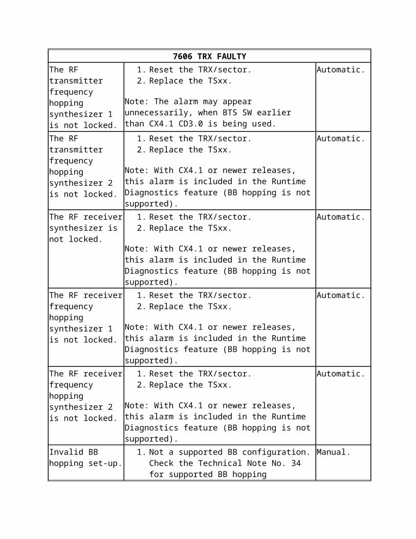
Figure: Tests menu and View Bar locations
The Test View screen consists two parts; The tabbed pane on the left and the Report Area on the right.
Tabbed Pane:
The tabbed pane displays the following tab sheets:
TRX Test (shown as default) Loop Test BCCH (Broadcast Control Channel) Transmission EAC (External Alarm Control) Input EAC Output TRX Continuous Transmission with BCCH Power level Cross Connection Validity Check
The test specific functions and information are displayed below the tabs.
Report Area:
This area is common for all the individual test tab sheets displaying two areas; Test Results and Test Details.
Test Results:
Test Type column specifies the Test or Diagnostic Tool executed Time column specifies the date and time stamp of the Tests executed Status column specifies the status of the Test or Diagnostic Tool executed
Values for tests:
Start Requested - implies the start request for Test has been sent to BTS. Ongoing - implies the requested Test has been started at BTS and BTS Manager has
received its acknowledgement. Stop Request - implies the stop request for Test has been sent to BTS. Passed / Partially Passed / Failed - are the status of the executed Test. Completed- the requested Test has been stopped at BTS and BTS Manager has received
its acknowledgement.
Values for diagnostic tool
Start Requested - implies the start request for Diagnostic Tool has been sent to BTS. Ongoing - implies the requested Diagnostic Tool has been started at BTS and BTS
Manager has received its acknowledgement. Stop Request - implies the stop request for Diagnostic Tool has been sent to BTS. Completed - implies the stop request has been acknowledged by BTS.
If you want to save or print the test reports use the buttons on the upper right hand corners of the Test Details and Test Results areas. The rightmost button on the Test Result area clears the test results.
Test Details:
This area displays the report of the test selected in the Test Results table. The test details can either be saved in xml format or printed.
Steps
1. Launch the BTS Manager.2. Click the Tests button on the View bar.3. Choose the test you wish to run.
Running a TRX test
Summary
The purpose of the TRX Test is to verify the TRX object's functionality. During TRX test session the BTS will execute various loops to gather the required measurement results. The test is carrier based, which can be run from TRX to TRX. The TRX test can be run only in one sector at a given time, that is the TRX test for both the sectors, in a same TRX module, cannot be run in parallel.
Choosing the Test | TRX Test command or clicking the Tests button in the View Bar opens the Tests view displaying the TRX Test tab sheet as default.
TRX Test tab enables the user to define the TRX Test configuration. Following selections are available:
TRX Number: Enables the user to select the TRX on which to execute the TRX test from a list that also shows the state icon of the TRX. Values are TRX 1 - TRX 24 and the default is the first available TRX.
The Configuring state has specific icon, the Supervisory state has no icon and rest of the states have error icon.
Time Slot: Enables the user to select the Time Slot on which execute the TRX test. Values: TS 0 - TS 7, default TS 0.
Modulation: Enables the user to select the modulation scheme. Values: GMSK / 8PSK, default GMSK.
Start: Enables the user to start the TRX test. The Start button will be disabled while execution of the TRX test, until the report arrives or negative acknowledgement (NACK) is received.
Note that
If the selected TRX is not in configuring/supervisory state, the TRX Test cannot be performed and the Start button will also be disabled.
If the selected TRX is in Locked Administrative state by the BSC the TRX Test cannot be performed and the Start button will also be disabled.
If the selected TRX is in the Shutdown state the TRX Test cannot be performed and the Start button will also be disabled.
Also note that the TRX test can not be run during BB hopping.
Steps
Expand/collapse all
1. Choose the TRX Test command on the Tests menu or choose the TRX Test tab sheet in the Tests view.
See the TRX test figure below.
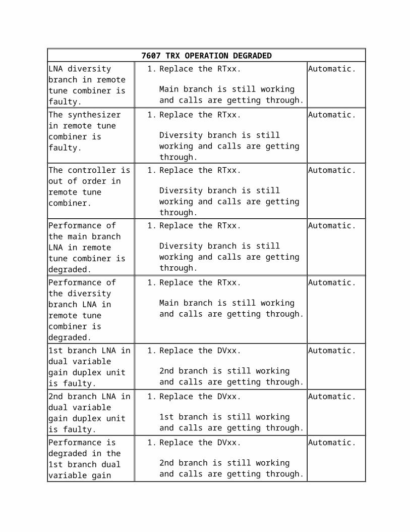
Figure: TRX test
2. Select the TRX Number on which test to be performed.3. Select Time Slot of the selected TRX.4. Select Modulation of the TRX.
5. Select the ARFN.
Note that the ARFN (Absolute Radio Frequency Number) value selection is only available in local mode. In network mode it is given by the BSC.
6. Click Start to execute test with selected parameters.
The Test report parameters are displayed on the Test Details pane:
Table: Test report parameters
Property Explanation
Test Result Indicates if the test has passed or failed
Failure Reason If a test has failed the reason for failure is shown here
Property Explanation
Timeslot Timeslot on which the TRX or Loop test is started
Tx Power1) Measured TX power level (dBm)
Main Rx BER 2) Measured Bit Error Ratio for Main receive branch (%)
Main Rx Result 3) Rx Result TRX Test for Main receive branch (dBm)
Diversity Rx BER 2) Measured diversity Bit Error Ratio for Diversity receive branch (%)
Diversity Rx Result 3) Rx Result TRX Test for Diversity receive branch (dBm)
1) Reported TX power is based on the measured RX level value, TRX loop module conversion loss and Power Level values stored in DTRX’s internal memory. Test fails if reported TX power level is outside +/- 4 dB of the nominal power value.
2) BER (Bit Error Ratio) shows % of the errors seen in the received data. Test fails if:
o BER > 2% in the RF part , oro BER > 0% in BB part
3) The Rx Result in TRX Test estimates the Rx Level needed by a single receiver for good quality decode of Full Rate speech. The Rx Result in TRX Test is calculated from Measurement of Noise & Interference Rx Level on an Idle radio channel Plus detection margins. The Rx Level reported includes masthead Amplifier (MHA) gain and cable loss allowances, depending on MHA type and configuration. Typical values are -85 dBm to -118 dBm in a normal operating environment.
The Rx Result in TRX Test is calculated from measurement of Noise & Interference Rx Level on an idle radio channel plus detection margin.
Note that the Diversity Rx BER and Diversity Rx Result are only shown if the BTS HW configuration supports RX diversity and the diversity is enabled on BSC (RDIV parameter set to Y)
The Test Results are displayed on the Test Results pane.
If the test fails look for troubleshooting instructions in the Troubleshooting TRX test and TRX loop test failures with BTS Manager section in the Trouble Management of Nokia Flexi EDGE BTS document.
Troubleshooting TRX test and TRX loop test failures with BTS Manager
Summary
Fault - TRX test or TRX loop test fails when test is executed locally or remotely with Nokia Flexi EDGE BTS Manager.
Steps
1. Determine the cause in TRX test/TRX loop test result column and corrective action.
Table: Troubleshooting TRX test/TRX loop test failures
TRX test/TRX loop test result
Reason for failure result Corrective action
"High power in Abis1-Air3 loop"
DTRX detects high power when receiving loop signal back from DDU/RTC. Either loopback switch in DDU/RTC or DTRX is causing the failure.
o Replace the Dual TRX module (EXxA).
o Replace the DDU module (ERxA) / RTC module (ECxA).
"Failure due to Forced Reset"
Either the DTRX or the RTC module was reset during the test.
o Wait until the module recovers from the reset.
o Run the TRX (loop) test again.
"Low BCCH Power levels"
The DTRX module received too low power looped back from DDU or RTC.
o Check all RF cabling between the DTRX module (EXxA) and DDU module (ERxA) / RTC module (ECxA).
o Replace the Dual TRX module (EXxA).
o Replace the DDU module (ERxA) / RTC module (ECxA).
"RF cables missing" The DTRX did not receive any loop signal back from DDU or RTC.
o Check all RF cabling between the DTRX module (EXxA) and DDU module (ERxA) / RTC module (ECxA).
o Replace the Dual TRX module (EXxA).
o Replace the DDU module (ERxA) / RTC module (ECxA).
TRX test/TRX loop test result
Reason for failure result Corrective action
"Failure due to TRX reconfiguration"
Test failed as TRX was reconfiguring. Wait until reconfiguration is finished.
o Run the TRX (loop) test again.
"Timeslot is busy" Test failed as the timeslot (and/or its pair timeslot) was busy.
o Wait until the timeslot is free or run the test again on a different timeslot.
o Note: Timeslot and its offset timeslot (-3) must both be free before the test can be run.
"Bad channel configuration"
TRX Test was attempted on BCCH or SDCCH timeslot.
o Find free non-BCCH / non-SDCCH timeslot and run the test again.
"Invalid AGC" Internal SW error occurred during the test.
o Reset BCF.
Note that this does not indicate a HW error - do NOT replace HW module(s).
"Channel mode is neither PS nor CS"
Internal SW error occurred during the test.
o Reset BCF.
Note that this does not indicate a HW error - do NOT replace HW module(s).
"Failed to set/clear air loop point as invalid path information"
Internal SW error occurred during the test.
o Reset BCF.
Note that this does not indicate a HW error - do NOT replace HW module(s).
"Failed to clear air loop point as TS already free"
Internal SW error occurred during the test.
o Reset BCF.
Note that this does not indicate a HW error - do NOT replace HW module(s).
"No response for block request for a timeslot"
Internal SW error occurred during the test.
o Reset BCF.
Note that this does not indicate a HW error - do NOT replace HW module(s).
"Phase loop lock (PLL) has alarm on
TRX loop synthesizer failure detected in DDU/RTC module.
o Replace the DDU module (ERxA) / RTC module
it"(ECxA).
"Not able to set the loop point on connected DDU/RTC or on ABIS within the predefined time"
Internal SW error occurred during the test.
o Reset BCF.
Note that this does not indicate a HW error - do NOT replace HW module(s).
"Failure in setting air loop point as DDU synthesizer not able to achieve Lock state"
TRX loop synthesizer failure detected in DDU/RTC module.
o Replace the DDU module (ERxA) / RTC module (ECxA).
"Failure due to high bit error ratio"
DTRX detected high BER during the TRX test.
o Check all RF cabling between the DTRX module (EXxA) and DDU module (ERxA) / RTC module (ECxA).
o Replace the Dual TRX module (EXxA).
o Replace the DDU module (ERxA) / RTC module (ECxA).
"Failure due to invalid loop gain"
DTRX received too high power looped back from DDU or RTC.
o Replace the Dual TRX module (EXxA).
o Replace the DDU module (ERxA) / RTC module (ECxA).
"Unable to measure power level"
DTRX received too low power looped back from DDU or RTC.
o Replace the DDU module (ERxA) / RTC module (ECxA).
o Replace the Dual TRX module (EXxA).
"Failure due to balance failure in Rx branches"
DTRX detected that Diversity and Main RX levels differed too much during the TRX test.
o Check all RX cabling between the DTRX module (EXxA) and DDU module (ERxA) / RTC module (ECxA).
o Replace the Dual TRX module (EXxA).
o Replace the DDU module (ERxA) / RTC module
(ECxA).
"Unable to measure Rx sensitivity"
Background noise could not be measured due to too high interference. Problem is probably caused by external interference (e.g. same frequency used nearby on another BTS).
o Run the TRX test again.o If the test fails persistently ,
the test should be run on a different frequency.
Note that sensitivity (RX result) is not based on BER. It is estimated from the background noise and interference level detected by DTRX at tested RX frequency.
"Failure in BB module"
HW failure was detected in DTRX.
o Replace the Dual TRX module (EXxA).
"No ARFN passed in loop command in configuring state"
Internal SW error occurred during the TRX test.
o Reset BCF.
Note that this does not indicate a HW error - do NOT replace HW module(s).
"Loop test error more than specified limit"
DTRX detected BER > 2 % during the TRX test.
o Check all RF cabling between the DTRX module (EXxA) and DDU module (ERxA) / RTC module (ECxA), replace faulty cables.
o Replace the Dual TRX module (EXxA).
o Replace the DDU module (ERxA) / RTC module (ECxA).
o If the test fails persistently , the test should be run on a different frequency.
“TRX is in shutdown state”
Test failed as TRX was in shutdown state.
o Wait until TRX is back in supervisory state.
o Run the TRX test again.
"RTC not in Supervisory State"
Test failed as RTC was not in supervisory state during the TRX test.
o Wait until the RTC reached Supervisory state.
o Run the TRX test again.
Further information
Note that after each troubleshooting step, run the TRX (loop) test again and if the problem still exists, go to the next troubleshooting step.
If WBC (EWxA) module is used, then the related RF cables and the WBC module should be checked as well in all cases where the instruction says: “Check and correct all the RF cabling between the DTRX module (EXxA) and DDU module (ERxA) / RTC module (ECxA), replace faulty cables”.
Troubleshooting Dual TRX Module (EXxA) operation
Summary
Fault – Dual TRX Module is not operating correctly
Steps
1. Determine the cause and corrective action.
Table: Troubleshooting Dual TRX Module operation
Potential cause Corrective action
Objects are locked from the BSC, NMS/2000 or NetAct.
o Request the state from the BSC or NetAct.o Request an unlock from the BSC or NetAct.
Objects are blocked from Nokia Flexi EDGE BTS Manager.
Unblock the object using Nokia Flexi EDGE BTS Manager.
Dual TRX Module is not properly connected, no electric power, or the LED is broken (the front LED does not light up).
o Check the power cable connections between the System Module (ESMA) or the System Extension Module (ESMA) and the Dual TRX Module.
o Check all RF cable connections between the Dual TRX Module and the Dual Duplexer Module (ERxA), Wideband Combiner Sub-module (EWxA) or Remote Tune Combiner Module (ECxA).
o Check the instructions in Troubleshooting electrical power.
o Replace the Dual TRX Module.
Potential cause Corrective action
After recovery from Intelligent Shutdown, the administrative state of TRX object(s) remain BL-RSL on BSC.
First, check if 7601 - 'Module power cable connections are incorrectly configured' alarm is active and follow the related troubleshooting instructions, if needed.
Note: During Intelligent shutdown, the BTS SW cuts off the power supply (from ESMA System Module's 'PWR' port) and LapD links for the affected TRX's and during recovery, turns them back on. Now, if the DTRX power cabling from the ESMA is incorrect (DTRX's power cable is not connected to the right 'PWR' port on ESMA), some TRX objects are left to blocked state as the recovery actions are routed to wrong DTRX. In this case, give TRX reset for the affected TRX objects.
After TRX/BTS/BCF reset, it takes one hour to activate Alarm 7606 TRX FAULTY "EXxx TRX module Tx power is less than minimum at DPC" for TCH TRX.
Flexi EDGE BTS has an antenna boosting feature when only TCH TRXs are connected to an antenna. The feature transmits shortly adequate TX power from one TCH TRX to its antenna port once in an hour when the transmission is observed as inadequate for this time period. One hour timer is fixed and is not configurable. Note that the antenna boosting does not interrupt possibly ongoing traffic. If observed antenna related problem during antenna boosting, the alarm can only be generated for Dual Duplexer Module (ERxA) and only when BB nor antenna hopping is not configured.
o Follow the troubleshooting instructions for the alarm.
2. Report damage, failure, or fault.
Replacing module fans for EXxA and ECxA
Purpose
If a module fan fails or becomes degraded, replace it with a new one.
In stack, wall, pole and Flexi Cabinet for Indoor (FCIA) installation, fans can be replaced from the back of the module if there is enough space behind the BTS. For information on the required clearances for maintenance, see Requirements for Installation and Operation.
When removing fans from the back of FCIA, you need to remove the back panel. For instructions, see Maintaining Flexi Cabinet for Indoor.
If there is not enough space for replacing the fans from the back, you can also replace the fans from the front. In this case you need to disable power to the module and pull it out from the casing or cabinet. For instructions on how to remove the module, see Replacing modules.
In Flexi Cabinet for Outdoor (FCOA), fans are replaced from the front.
Note that when replacing fans, an alarm indicating a broken fan may be seen. After you have replaced the fan, the alarm is cancelled.
The product code of the fan plate assembly is 0831808.
Before you start
Shut down the module before replacing fans. See instructions in Replacing modules.
Warning
Risk of personal injury. Do not touch the rotating fans.
Caution
The modules may be damaged if operated for a long time in the upper ambient temperature range. Replace a faulty unit as soon as possible.
Summary
Figure: Replacing module fans (EXxA is shown)
Steps
Expand/collapse all
1. Block the TRXs associated with the module with the faulty fan assembly with Nokia Flexi EDGE BTS Manager or, if Baseband or Antenna Hopping is used, block the whole sector.
2. Connect the ESD wrist strap.3. Wait for stable yellow LED to be displayed.
4. Disable power to the module with the Flexi EDGE BTS Manager.
5. If this is a pole, wall, stack, or FCIA installation with back maintenance access, remove the back cover or wall.
6. If back maintenance access is not available, remove the module.
7. Pull the fan connector out of the module.8. Detach the three screws on the fan assembly.9. Slide the fan assembly out.10. Slide the new fan assembly in.11. Tighten the screws.
12. Connect the fan connector.
13. If the module was removed, reinstall the module and its cables.
14. Enable power to the module with the Flexi EDGE BTS Manager.
15. Check that the new fans start to rotate.16. Check that the fan alarm (which was activated when the faulty fan module was removed)
is cancelled from Nokia Flexi EDGE BTS Manager. 17. Unblock the TRXs or sector with Nokia Flexi EDGE BTS Manager.18. Re-install any removed cable entries, covers, or back wa
7601 BCF OPERATION DEGRADED
Table: BCF OPERATION DEGRADED
7601 BCF OPERATION DEGRADED
Severity: Object affected: Object state: Module/Unit:
Major BCF Enabled ESMA
Fault reason: Instruction: Alarm cancelling:
Difference between PCM and BTS frequency reference.
There is over 5 Hz difference to the 2MHz reference clock due to Abis link instability.
Automatic.
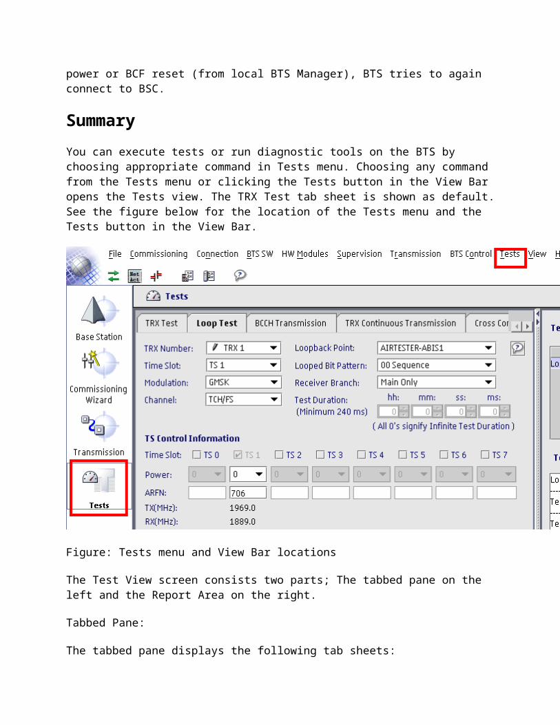
7601 BCF OPERATION DEGRADED
1. Check that Synchronisation priority list has correct Rx clock sources.
2. Check the Abis link quality (G.826 performance statistics via BTS Manager/NetAct). Check the alarm history for 8xxx alarms reported and resolve any link problems occurred.
3. Check the network synchonisation between the BSC and the base station.
4. If alarm is active at multiple sites, check the quality of synchronisation for the whole BSS.
ESMA System module has lost connection to FSEx External Alarm (EAC) module.
FSEx External Alarm (EAC) module does not respond to poll message of the ESMA System module.
1. Check that FSEx is set to Active Mode by connecting pins 3-4 of X1103 jumper.
2. Check that the cabling is correctly mated between ESMA and FSEx.
3. Replace FSEx.4. Replace ESMA.
Automatic.
ESMA System module cooling fan(s) report no rotation.
One or more fans of the ESMA System module are not rotating. There is a danger of overheating.
1. Check that the fan unit cable is correctly mated to ESMA.
2. Check that there are no obstacles preventing the fan(s) from rotating.
3. Clean the fan unit of dust and/or dirt.4. Replace the fan unit.5. Replace ESMA.
Automatic.
Commissioning failed due to BCF ID mismatch between commissioning file and BSC
Incorrect BCF ID between the BSC and the Commissioning File (SCF).
1. Check the transmission path of the traffic allocated to the site against the network plan.
2. Using the (remote) BTS Manager, recommission the BTS with correct BCF ID.
Automatic.
ESMA System module Memory write failure occurred at SW download and Manual.
7601 BCF OPERATION DEGRADED
FLASH memory writing error.
is not valid, previously active SW is taken into use.
1. Issue a HW reset to ESMA from (remote) BTS Manager.
2. Attempt the SW download again.3. If this alarm persists, replace ESMA.
All external Q1 devices fail to respond.
None of the configured Q1 devices in the Q1 bus are responding to a polling command.
1. Check that Q1 addresses and baud rate match between the Q1 devices and BSC.
2. If FIFA is used and BTS is polling Q1 equipment, check that Q1 switch towards the Q1 bus is closed with FlexiHub Manager.
3. Check that the Q1 cables are correctly mated between the ESMA and Q1 devices.
4. Replace ESMA.
Automatic.
Commissioning file climate control profile mismatch, no fans detected.
Climate control profile indicates an installed fan unit but it is missing from the actual configuration. There is a danger of overheating.
1. If none of the modules at the site require fan units, change the fan profile to "No Fans" in the SCF and re-commission the site.
2. Check that the fan unit cable is correctly mated to ESMA.
3. Replace the fan unit.4. Replace the ESMA.
Automatic.
Module power cable connections are incorrectly configured.
One or more of the internal power cable connections does not match power cabling rules. Intelligent shutdown feature may not operate correctly.
1. Check the internal power and bus cabling against the product documentation set.
2. Issue a BCF reset.
7602 BCF NOTIFICATION
Table: 7602 BCF NOTIFICATION
7602 BCF NOTIFICATION
Severity: Object affected: Object state: Module/Unit:
Minor BCF Enabled ECxA, ESEA, ESMA, EXxA
Fault reason: Instruction: Alarm cancelling:
External synchronisation signals disabled.
LMU has operated without GPS signal over specified time and is turning its FCLK output off.
1. Check the GPS antenna fix status is OK with LMUManager. Adjust the GPS antenna so that satellites become visible.
2. Check that the GPS cable is correctly mated to LMU.
3. Check that the latest LMU SW is being used. Download newer SW if necessary.
4. Replace LMU.
Automatic.
BSS synchronisation failed. ESMA System module has lost synchronisation signal at synchronisation input (SIN) port.
1. If LMU provides the synchronisation, check if alarm 8202 is active and resolve it.
2. If another BTS is the synchronisation master, check if that it is up and alive.
3. Check that the synchronisation cabling is correctly mated between the units. If LMU is used, check also Q1 cabling and power supply to the LMU unit.
4. Replace ESMA.
Automatic.
ESMA System module cooling fan speed has deviated from the set speed.
There is more than 20% deviation in fan speed between commanded and actual value.
1. Check that nothing obstructs the fan(s) from rotating.
2. Clean the fan unit of dust and/or dirt.
Automatic.
7602 BCF NOTIFICATION
3. Replace the fan unit. Note: If "Temperature high/dangerously high" and/or 7621 alarm(s) are also active, perform these actions as soon as possible.
ESMA System module temperature high.
ESMA System module has detected that its internal temperature has exceeded +90C/+194F.
1. Ensure that the ambient temperature of the base station is below +50C/+122F.
2. Check if any fan alarms are also active. If active, refer to fan alarm instructions to resolve.
3. Replace the ESMA.
Automatic.
ECxx RTC module connected to wrong port.
ECxx RTC module is not connected to port 1/2/3 of ESMA System module.
1. Connect ECxx to ESMA port 1,2 or 3 and issue a BCF reset.
Automatic.
EXxx TRX module connected to wrong port.
EXxx TRX Module is not connected to ESEA System Extension module.
1. Connect EXxx module to ESEA.
Automatic.
ESEA System Extension module connected to wrong port.
ESEA System Extension module is not connected to port 6 of ESMA System Module.
1. Connect ESEA to port 6 of ESMA, and issue a BCF reset.
Automatic.
Unknown module connected to ESxx System (Extension) module.
ESMA System module does not recognise the module connected to this port. SW release incompatibility with the connected HW.
1. Check the HW \ SW compatibility from the SW release binder.
a. If the module is compatible with the current SW running in the BTS, replace the module.
b. If the module is not compatible with the current SW running in the BTS,
Automatic.
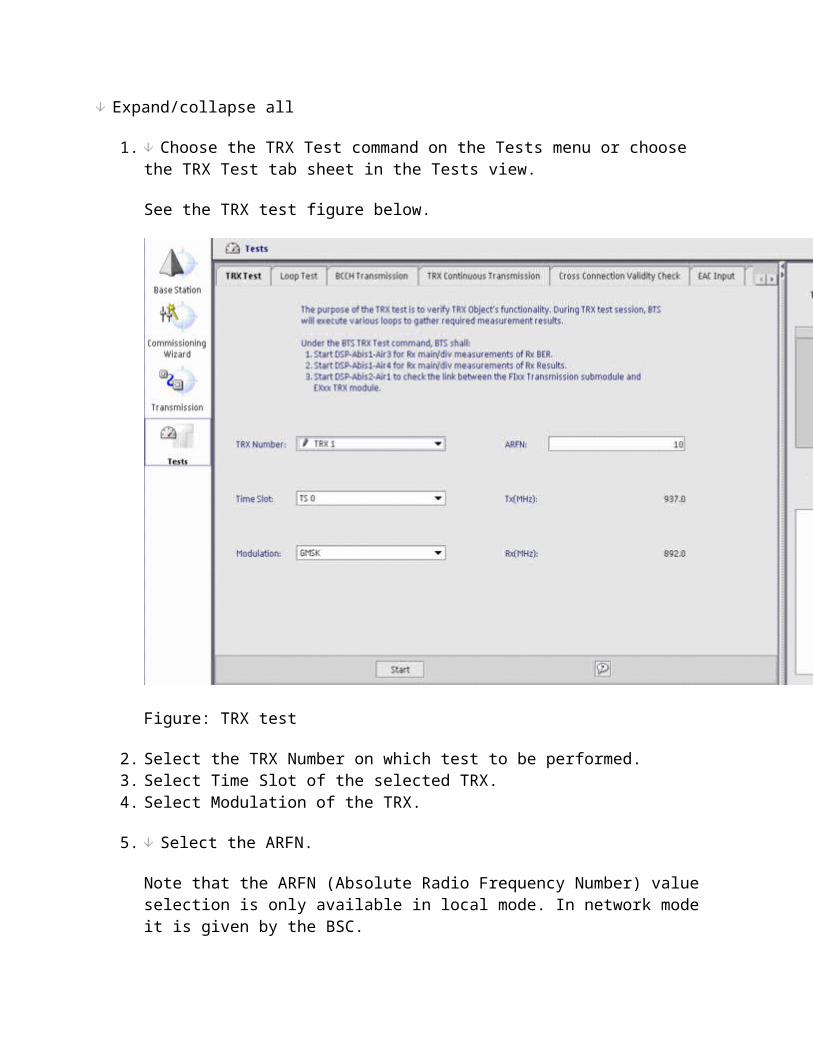
7602 BCF NOTIFICATION
check which SW version supports the module. Upgrade the BTS SW to the version that supports the module.
2. Remove the unknown module
ESEA System Extension module temperature high.
Internal temperature of ESEA System Extension module has exceeded +90C/+194F.
1. Ensure that the ambient temperature of the base station is below +50C/+122F.
2. If the fault persists, replace ESEA.
Automatic.
ESMA System module unable to read internal temperature sensors.
There is no temperature measurement in the ESMA System module. All temperature sensors inside the module are broken. Fans are rotating at maximum speed.
1. Replace the ESMA. Note: If fan alarm(s) are active at ESMA, perform this action as soon as possible.
Automatic.
7603 BTS FAULTY
Table: 7603 BTS FAULTY
7603 BTS FAULTY
Severity: Object affected: Object state: Module/Unit:
Critical BTS Disabled ECxx, ERxx
Fault reason:
Instruction: Alarm cancelling:
Other faults.
1. Check whether either of the following alarms is active:
7606 TRX FAULTY
7607 TRX OPERATION DEGRADED
and follow the instructions given for the active alarm(s).
Automatic.
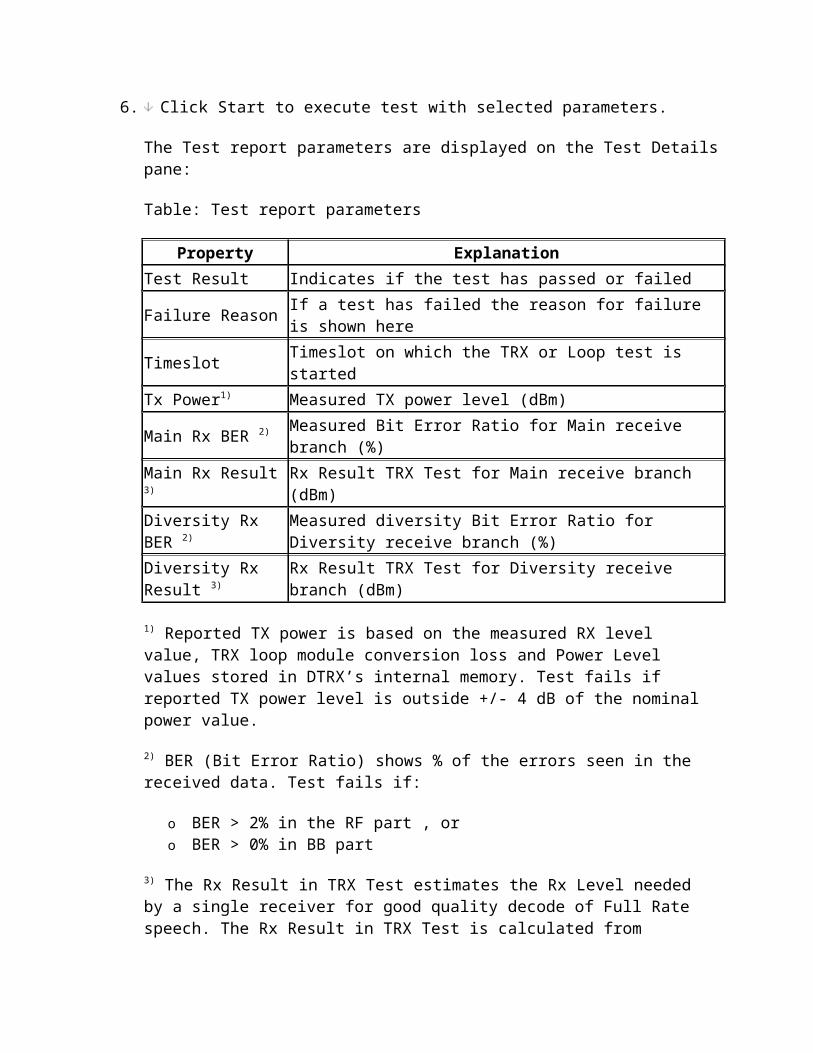
7604 BTS OPERATION DEGRADED
Table: 7604 BTS OPERATION DEGRADED
7604 BTS OPERATION DEGRADED
Severity: Object affected: Object state: Module/Unit:
Critical BTS Enabled ECxx, ERxx
Fault reason: Instruction: Alarm cancelling:
Other faults. 1. Check whether either of the following alarms is active:
7606 TRX FAULTY
7607 TRX OPERATION DEGRADED
and follow the instructions given for the active alarm(s).
Automatic.
7605 BTS NOTIFICATION
Table: 7605 BTS NOTIFICATION
7605 BTS NOTIFICATION
Severity: Object affected: Object state: Module/Unit:
Minor BTS Enabled ECxA
Fault reason: Instruction: Alarm cancelling:
ECxx RTC module temperature dangerously high.
ECxx RTC module has detected that its internal temperature has exceeded +65C/+149F.
1. Ensure that the ambient temperature of the base station is below +50C/+122F.
2. Check if any fan alarms are also active. If active, refer to fan alarm instructions to resolve.
3. Replace the ECxx.
Automatic.
ECxx RTC module cooling fan(s) report no rotation.
One or more fans of the ECxx RTC module are not rotating. There is a danger of overheating.
1. Check that the fan unit cable is correctly mated to ECxx.
2. Check that there are no obstacles preventing the fan(s) from rotating.
Automatic.
7605 BTS NOTIFICATION
3. Clean the fan unit of dust and/or dirt.4. Replace the fan unit.5. Replace ECxx.
ECxx RTC module cooling fan speed has deviated from the set speed.
There is more than 20% deviation in fan speed between commanded and actual value.
1. Check that nothing obstructs the fan(s) from rotating.
2. Clean the fan unit of dust and/or dirt.3. Replace the fan unit. Note: If "Temperature
high/dangerously high" and/or 7621 alarm(s) are also active, perform these actions as soon as possible.
7606 TRX FAULTY
Table: 7606 TRX FAULTY
7606 TRX FAULTY
Severity: Object affected: Object state: Module/Unit:
Major TRX Disabled ECxA, ERxA, ESMA, EXxA
Fault reason: Instruction: Alarm cancelling:
Hardware incompatibility detected during EXxx TRX module configuring.
Frequency band/channel or BTS configuration mismatch between the BTS units and BSC configuration.
1. Check that the EXxx, ECxx/ERxx module is of correct frequency (sub-)band as configured in the BSC.
2. Check that RF hopping is not used when ECxx is installed.
3. Modify BSC parameters against the actual configuration at the site.
4. Replace EXxx or ERxx/ECxx.
Automatic
EXxx TRX module has no There is no ERxx DDU module or ECxx RTC Manual.
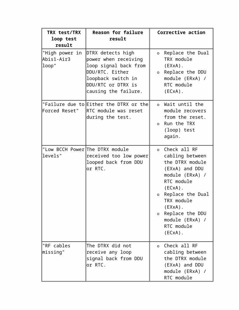
7606 TRX FAULTY
combiner ERxx DDU or ECxx RTC module present.
module detected for the sector at start up.
1. Depending on the desired configuration:
a. Connect/check ER_A cable between ERxx and EXxx for the associated sector and issue a sector reset. OR
b. Connect/check bus cable between ECxx and ESMA and issue a sector reset.
2. Replace ERxx/ECxx.3. Replace EXxx.
EXxx TRX module incoming frame clock FCLK missing.
EXxx TRX module has detected that the Frame Clock coming from the ESMA System module is missing. FCLK is generated by ESMA System module which is distributed to EXxx TRX modules either directly or via ESEA.
1. Check the bus cable chain from ESMA to EXxx.
Caution
If bus cables are looped back to the same module, ongoing calls may be dropped or a module may freeze until the loop is removed. Do not loop bus cables back to the same module.
2. Replace EXxx.3. Replace ESEA if alarming TRX is connected
to it.4. Replace ESMA.
Automatic
EXxx TRX module failed to synchronize to incoming frame clock FCLK.
EXxx TRX module has detected that it cannot synchronise to the Frame Clock. FCLK is generated by ESMA System module which is distributed to EXxx TRX modules either directly or via ESEA.
1. Check the bus cable chain from ESMA to EXxx. Issue a HW Reset to EXxx.
Manual.
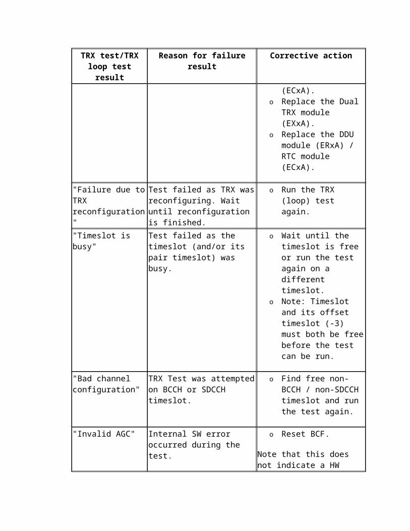
7606 TRX FAULTY
Caution
If bus cables are looped back to the same module, ongoing calls may be dropped or a module may freeze until the loop is removed. Do not loop bus cables back to the same module.
2. Replace EXxx.3. Replace ESMA.4. Replace ESEA.
EXxx TRX module incoming 6.5 MHz reference clock missing.
EXxx TRX module has detected that the 6.5 MHz reference clock coming from the ESMA System module is missing. The 6.5 MHz reference is generated by ESMA System module which is distributed to EXxx TRX modules either directly or via ESEA.
1. Check the bus cable chain from ESMA to EXxx.
Caution
If bus cables are looped back to the same module, ongoing calls may be dropped or a module may freeze until the loop is removed. Do not loop bus cables back to the same module.
2. Replace EXxx.3. Replace ESEA if alarming TRX is connected
to it.4. Replace ESMA.
Automatic.
EXxx TRX module temperature dangerously high.
EXxx TRX module has detected that its internal temperature has exceeded +95C/+203F.
1. Ensure that the ambient temperature of the base station is below +50C/+122F
2. Check if any fan alarms are also active. If active, refer to fan alarm instructions to
Automatic.
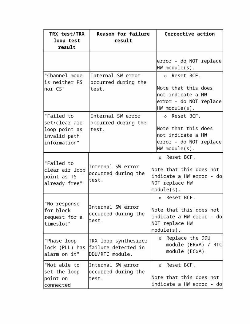
7606 TRX FAULTY
resolve.3. Replace the EXxx.
Internal failure occurred during EXxx TRX module configuring.
There was no internal response or timeout occurred during EXxx TRX module configuration.
1. Reset the EXxx to allow unit reconfiguration.2. If alarm persists, replace EXxx.
Manual TRX lock/unlock.
ERxx DDU module SW activation fails.
ERxx DDU module did not activate inactive SW and therefore it is running with current active package.
1. Issue a HW reset to EXxx.2. If alarm reappears after ERxx SW download,
replace ERxx.
Manual.
ERxx DDU module not supported.
Connected module is either of wrong network type or device type.
1. Check that the connected ERxx is of correct frequency band in respect to the used EXxx.
2. Check that ERxx is connected to EXxx.3. Replace ERxx.
Manual.
ERxx DDU module reported HW failure.
At startup ERxx DDU module reported internal HW failure.
1. Replace ERxx.
Manual.
ESMA System module has lost connection to EXxx TRX module.
EXxx TRX or ECxx RTC module does not respond to polling command from ESMA System module. EXxx TRX module can be connected to ESMA either directly or via ESEA System Extension module.
DTRX Case:
1. Check the bus cable chain from ESMA to EXxx.
Caution
If bus cables are looped back to the same module, ongoing calls
Automatic.
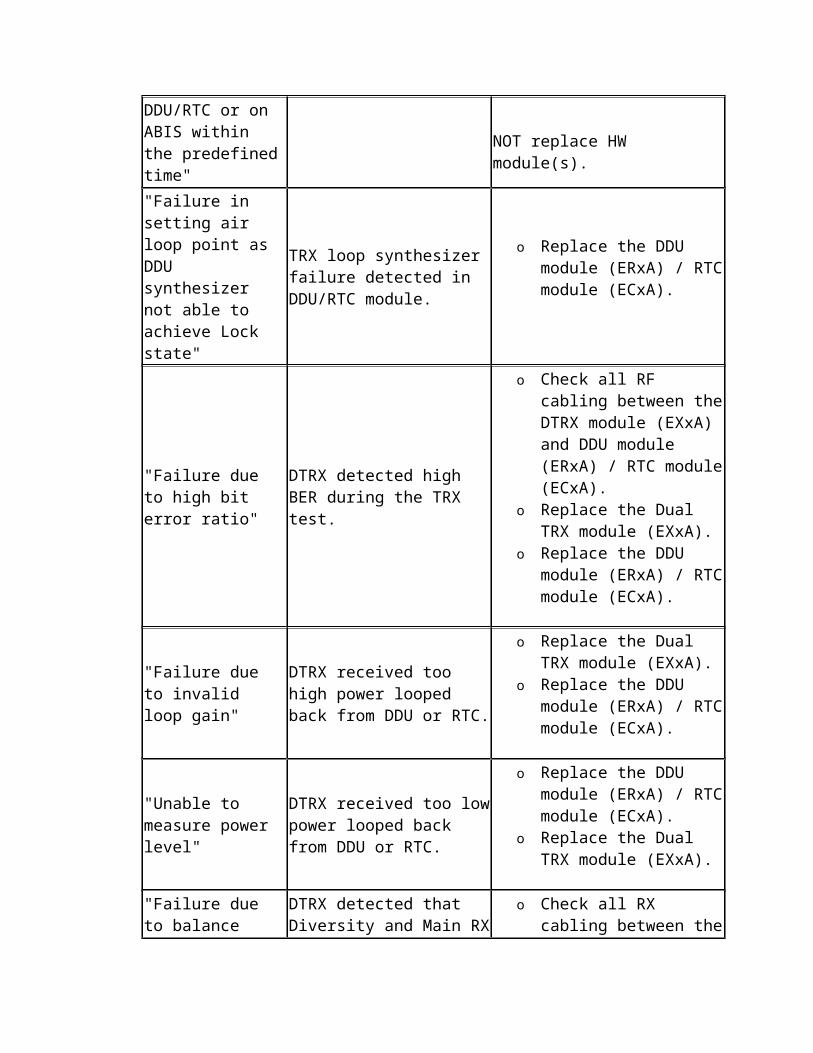
7606 TRX FAULTY
may be dropped or a module may freeze until the loop is removed. Do not loop bus cables back to the same module.
2. If the EXxx LED is off, replace the power cable.
3. Replace EXxx.4. Replace ESEA if alarming TRX is connected
to it.5. Replace ESMA.
RTC Case:
1. Check the bus cable chain from ESMA to ECxx.
Caution
If bus cables are looped back to the same module, ongoing calls may be dropped or a module may freeze until the loop is removed. Do not loop bus cables back to the same module.
2. If the ECxx LED is off, replace the power cable.
3. Replace ECxx.4. Replace ESMA.
EXxx TRX module has lost connection to ERxx DDU module
ERxx DDU module is not responding to poll command from EXxx TRX module.
1. Check that the ER_A cable is correctly mated between EXxx and ERxx.
2. Replace ERxx.3. Replace EXxx.
Automatic.
Internal failure occurred during ERxx DDU module configuring.
ERxx DDU module configuration (Gain or Bias-T) failed.
1. Reset the EXxx to allow ERxx unit reconfiguration.
Manual.
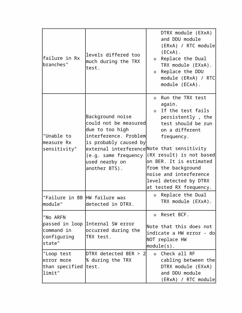
7606 TRX FAULTY
2. If the alarm reappears, replace ERxx.
EXxx TRX module has missing transmission time slot allocation.
TRXsig and/or TCH allocation for EXxx TRX module is missing from the Abis allocation.
1. Check that BTS configuration and Abis time slot allocation matches between the SCF, installed units and the BSC.
2. Add missing time slot allocation to the SCF/BTS by appending the commissioning file.
Automatic.
EXxx TRX module SW download from ESMA System module failed.
ESMA System Module detected that SW download to EXxx TRX module has failed repeatedly at TRX startup. EXxx TRX module can be connected to ESMA either directly or via ESEA System Extension module.
1. Check the bus cable chain from ESMA to EXxx.
Caution
If bus cables are looped back to the same module, ongoing calls may be dropped or a module may freeze until the loop is removed. Do not loop bus cables back to the same module.
2. Replace EXxx.
Automatic.
ECxx RTC module internal HW failure.
At startup ECxx RTC module reported internal HW failure.
1. Replace ECxx.
Automatic.
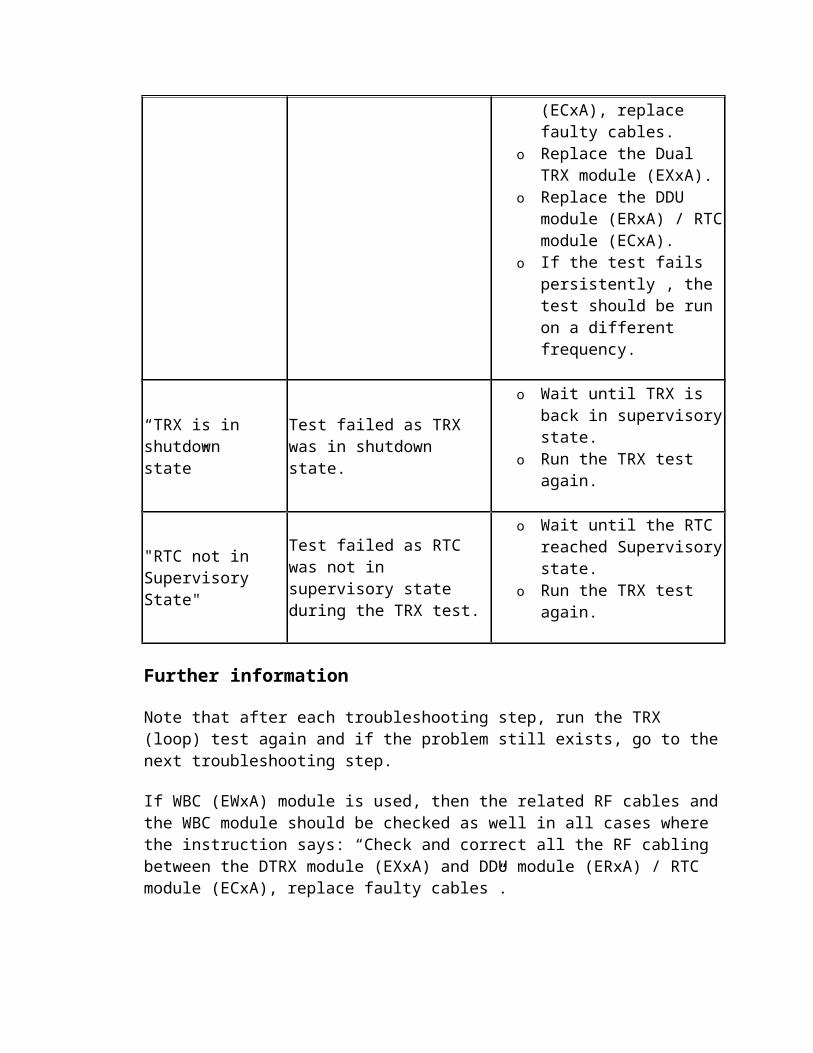
7606 TRX FAULTY
ECxx RTC module SW download from ESMA System module failed.
ESMA System Module detected that SW download to ECxx RTC module has failed at startup.
1. Issue a HW reset to ESMA.2. If alarm persists, replace ECxx.3. Replace ESMA.
Automatic.
EXxx TRX module failed to synchronize to incoming frame clock FCLK.
ECxx RTC module has detected that the Frame Clock coming from the ESMA System module is missing.
1. Issue a HW reset to ESMA.2. Check that the bus cable is correctly mated
between the ECxx and ESMA.
Caution
If bus cables are looped back to the same module, ongoing calls may be dropped or a module may freeze until the loop is removed. Do not loop bus cables back to the same module.
3. Check whether other ECxx modules have the same alarm, replace ESMA.
4. Replace ECxx.
Automatic.
ECxx RTC module received insufficient Tx power.
ECxx RTC module detected insufficient power during cavity tuning. RTC is unable to perform cavity tuning.
1. Issue a sector lock/unlock to allow ECxx RTC module reconfiguration.
2. Check that the Tx cabling between EXxx and ECxx is correctly mated. Check also the condition of cables.
3. If all the EXxx connected to the ECxx have raised this alarm, replace ECxx.
4. Replace EXxx.5. Replace ECxx.
Automatic.
EXxx TRX module Tx hopping synthesizer 1 fails
Tx hopping synthesizer 1 in EXxx TRX module was Manual.
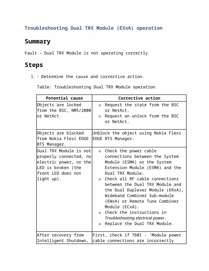
7606 TRX FAULTY
to lock. unable to (maintain) lock to the given channel.
1. Reset TRX/Sector.2. Replace EXxx.
EXxx TRX module Tx hopping synthesizer 2 fails to lock.
Tx hopping synthesizer 2 in EXxx TRX module was unable to (maintain) lock to the given channel.
1. Reset TRX/Sector.2. Replace EXxx.
Manual.
EXxx TRX module Rx hopping synthesizer 1 fails to lock.
Rx hopping synthesizer 1 in EXxx TRX module was unable to (maintain) lock to the given channel.
1. Reset TRX/Sector.2. Replace EXxx.
Manual.
EXxx TRX module Rx hopping synthesizer 2 fails to lock.
Rx hopping synthesizer 2 in EXxx TRX module was unable to (maintain) lock to the given channel.
1. Reset TRX/Sector.2. Replace EXxx.
Automatic.
EXxx TRX module Rx fixed frequency synthesizer fails to lock.
Rx fixed frequency synthesizer in EXxx TRX module was unable to (maintain) lock to the given channel.
1. Reset TRX/Sector.2. Replace EXxx.
Manual.
EXxx TRX module Tx power is less than minimum at DPC.
Tx output power is less than +14.5dBm at Digital Power Control circuit block in EXxx TRX module.
1. Replace EXxx.
Manual.
EXxx TRX module Tx power overdriven at DPC.
Tx output power is over 2 dB higher than expected at Digital Power Control circuit block in EXxx TRX module.
1. Replace EXxx.
Manual.
EXxx TRX module detected no connection to
RF cable autodetection failed due to no Tx or Rx connectivity from EXxx TRX module to ERxx DDU
Manual.
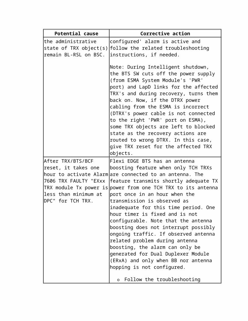
7606 TRX FAULTY
ERxx DDU via RF cable autodetection.
module. All Rx measurement report values for a TRX object were below connectivity threshold.
1. Check that the Tx and Rx cables between EXxx, EWxx and ERxx or ECxx are correctly mated and the connectors and cables are not damaged. Issue a sector reset to restart RF cable autodetection.
2. Replace EXxx.
EXxx TRX module detected no Rx signal during RF cable autodetection.
RF cable autodetection failed due to no Rx connectivity from EXxx TRX module to ECxx RTC module. All Rx measurement report values for a TRX object were below connectivity threshold.
When this alarm is active, BTS Manager does not display any RF cabling.
1. Check that the Rx cables between EXxx and ECxx are correctly mated with defined torque and the connectors are not damaged. Issue a sector reset to restart RF cable autodetection.
2. Check that ECxx and EXxx are of same frequency band.
3. If all the EXxx connected to the ECxx have raised this alarm, replace ECxx.
4. Replace EXxx.
Manual.
Two or more ERxx DDU modules detected in 2- or 4-way combined sector.
RF cable autodetection detected that current combining method does not allow more than one ERxx DDU module in a sector.
1. Check that the Tx cabling from EXxx and EWxx modules in one sector are connected to the same ERxx module.
2. Remove extra ERxx from the sector.
Manual.
ERxx DDU module has detected no Tx power at TxA input.
There is no Tx power detected at TxA input of ERxx DDU module.
1. Check the whole Tx cabling chain between EXxx, EWxx (upon usage) and ERxx that they are correctly mated between the units.
2. Check that the cables are not damaged or bent
Manual Sector lock/unlock.
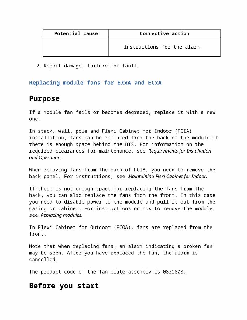
7606 TRX FAULTY
too sharply. 3. Replace EXxx. 4. Replace ECxx. 5. Replace EWxx.
ERxx DDU module has detected no Tx power at TxB input.
There is no Tx power detected at TxB input of ERxx DDU module.
1. Check the whole Tx cabling chain between EXxx, EWxx (upon usage) and ERxx that they are correctly mated between the units.
2. Check that the cables are not damaged or bent too sharply.
3. Replace EXxx. 4. Replace ECxx.5. Replace EWxx.
Manual Sector lock/unlock.
ERxx DDU module has detected VSWR above major limit at antenna A.
User definable major alarm threshold for VSWR measurement has been exceeded. The default value is 3.1.
1. Check the condition of the feeder and jumper cable, their connectors, sockets and connector seals starting from BTS end and proceed towards the antenna end. Replace damaged feeder cable.
2. If MHA is used, check that it is of correct (sub)band.
3. With external test equipment, measure the Return loss/VSWR of the antenna line. Perform step 1 again, if the measurement result is higher than expected.
4. Revise the VSWR alarm threshold by appending the commissioning.
5. Replace ERxx.
Manual.
ERxx DDU module has detected VSWR above major limit at antenna B.
User definable major alarm threshold for VSWR measurement has been exceeded. The default value is 3.1.
1. Check the condition of the feeder and jumper cable, their connectors, sockets and connector seals starting from BTS end and proceed towards the antenna end. Replace damaged
Manual.
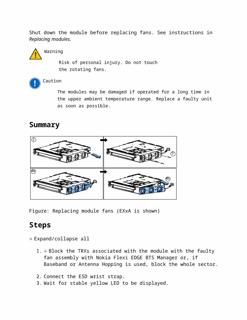
7606 TRX FAULTY
feeder cable.2. If MHA is used, check that it is of correct
(sub)band.3. With external test equipment, measure the
Return loss/VSWR of the antenna line. Perform step 1 again, if the measurement result is higher than expected.
4. Revise the VSWR alarm threshold by appending the commissioning.
5. Replace ERxx.
ECxx RTC module has lost Tx power from all inputs.
No Tx power detected from any of the TRXs connected to ECxx RTC module. Note: This alarm might take upto one hour to appear after RTC module is reset.
1. Issue a sector reset and run a TRX test for each TRX.
2. Check the Tx cabling from all the TRXs and issue a sector reset. Run a TRX test for each TRX.
3. If the alarm persists, replace ECxx.
Manual.
ECxx RTC module has detected VSWR above major limit at antenna.
User definable major alarm threshold for VSWR measurement has been exceeded. The default value is 3.1.
1. Check the condition of the feeder and jumper cable, their connectors, sockets and connector seals starting from BTS end and proceed towards the antenna end. Replace damaged feeder cable.
2. If MHA is used, check that is of correct (sub)band.
3. With external test equipment, measure the Return loss/VSWR of the antenna line. Perform step 1 again, if the measurement result is higher than expected.
4. Revise the VSWR alarm threshold by appending the commissioning.
5. Replace ECxx.
Manual Sector lock/unlock.
Main Rx LNA amplifier Both low noise amplifiers in a balanced stage have Manual.
7606 TRX FAULTY
chain is broken in ECxx RTC module.
failed for the main branch of the ECxx RTC module. The diversity branch is either not configured or it is broken.
1. Replace ECxx.
ECxx RTC module has detected that MHA on ANT A is broken.
Measured current consumption of Mast Head Amplifier has either exceeded the upper limit or dropped below the lower limit. MHA bypass is not configured/equipped.
The upper and lower limits are user definable during commissioning.
1. Check that the current min/max limits and MHA settings correspond to the actual configuration.
2. Check the antenna line for any damage affecting the current supply to the MHA.
3. Replace MHA.4. Replace ECxx.
Manual.
ECxx RTC module has detected that MHA on ANT B is broken
Measured current consumption of Mast Head Amplifier has either exceeded the upper limit or dropped below the lower limit. MHA bypass is not configured/equipped.
The upper and lower limits are user definable during commissioning.
1. Check that the current min/max limits and MHA settings correspond to the actual configuration.
2. Check the antenna line for any damage affecting the current supply to the MHA.
3. Replace MHA.4. Replace ECxx.
Manual.
ECxx RTC module has detected no Tx power during RF cable autodetection.
RF cable autodetection failed due to no Tx connectivity from EXxx TRX module to ECxx RTC module.
1. Check that the Tx and Rx cables between EXxx and ECxx are correctly mated and the
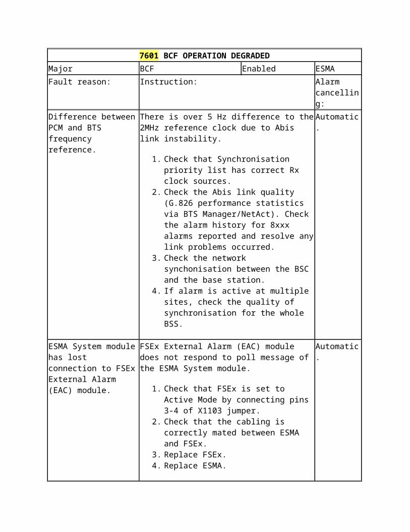
7606 TRX FAULTY
connectors and cables are not damaged. Issue a sector reset from EM to restart RF cable autodetection.
2. Check that ECxx and EXxx are of same frequency band.
3. Check that bus cable and internal power cable is correctly mated between ECxx and ESMA.
4. If all the EXxx connected to the ECxx have raised this alarm, replace ECxx.
5. Replace EXxx.6. Replace ECxx.
7607 TRX OPERATION DEGRADED
Table: 7607 TRX OPERATION DEGRADED
7607 TRX OPERATION DEGRADED
Severity: Object affected: Object state: Module/Unit:
Major TRX Enabled ECxA, ERxA, EXxA
Fault reason: Instruction: Alarm cancelling:
Path A of Rx LNA amplifier chain is broken in ERxx DDU module.
Both low noise amplifiers in a balanced stage have failed for Path A of ERxx DDU module. If diversity is used, Path B is still working.
1. Replace ERxx.
Automatic.
Path B of Rx LNA amplifier chain is broken in ERxx DDU module.
Both low noise amplifiers in a balanced stage have failed for Path B of ERxx DDU module. If diversity is used, Path A is still working.
1. Replace ERxx.
Automatic.
Path A of Rx LNA amplifier chain is broken in ECxx RTC module.
Both low noise amplifiers in a balanced stage have failed for main branch of ECxx RTC module. If diversity is used, the diversity
Automatic.
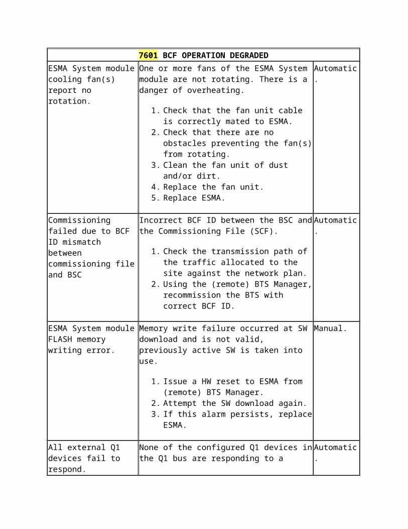
7607 TRX OPERATION DEGRADED
branch is still working.
1. Replace ECxx.
Path B of Rx LNA amplifier chain is broken in ECxx RTC module.
Both low noise amplifiers in a balanced stage have failed for diversity branch of ECxx RTC module. The main branch is still working.
1. Replace ECxx.
Automatic.
ERxx DDU module has detected that MHA on its antenna A is broken.
Measured current consumption of Mast Head Amplifier has either exceeded the upper limit or dropped below the lower limit. MHA bypass is not configured/equipped. The upper and lower limits are user definable during commissioning.
1. Check that the current min/max limits and MHA settings correspond to the actual configuration.
2. Check the antenna line for any damage affecting the current supply to the MHA.
3. Replace MHA.4. Replace ERxx.
Conditional Automatic, if the current consumption returns back within defined limits and has not exceeded 1A at any point. Manual, if current consumption exceeded 1A, because Bias-T supply is switched off to prevent damage. Cancellation via Sector lock/unlock.
ERxx DDU module has detected that MHA on its antenna B is broken.
Measured current consumption of Mast Head Amplifier has either exceeded the upper limit or dropped below the lower limit. MHA bypass is not configured/equipped. The upper and lower limits are user definable during commissioning.
1. Check that the current min/max limits and MHA settings correspond to the actual configuration.
2. Check the antenna line for any damage affecting the current supply to the MHA.
3. Replace MHA.4. Replace ERxx.
Conditional Automatic, if the current consumption returns back within defined limits and has not exceeded 1A at any point. Manual, if current consumption exceeded 1A, because Bias-T supply is switched off to prevent damage. Cancellation via Sector lock/unlock.
ECxx RTC module Measured current consumption of Mast Head Conditional Automatic, if the
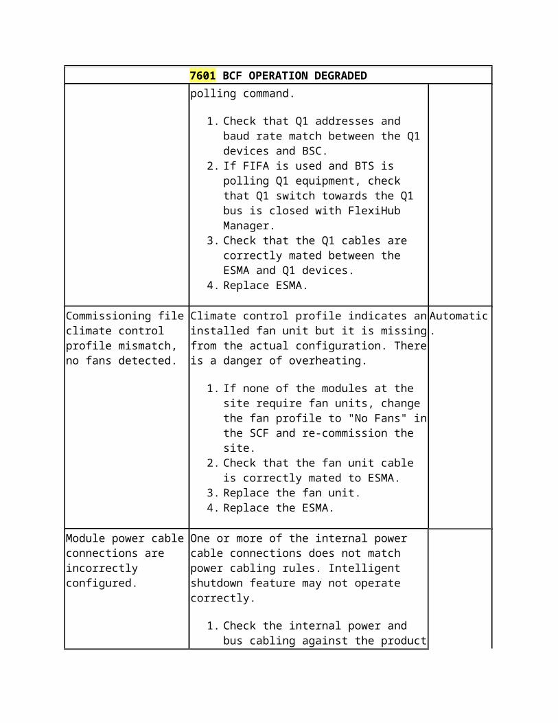
7607 TRX OPERATION DEGRADED
has detected that MHA on its antenna A is broken.
Amplifier has either exceeded the upper limit or dropped below the lower limit. MHA bypass is not configured/equipped. The upper and lower limits are user definable during commissioning. If diversity is used, diversity antenna is still working.
1. Check that the current min/max limits and MHA settings correspond to the actual configuration.
2. Check the antenna line for any damage affecting the current supply to the MHA.
3. Replace MHA. 4. Replace ECxx.
current consumption returns back within defined limits and has not exceeded 1A at any point. Manual, if current consumption exceeded 1A, because Bias-T supply is switched off to prevent damage. Cancellation via Sector lock/unlock.
ECxx RTC module has detected that MHA on its antenna B is broken.
Measured current consumption of Mast Head Amplifier has either exceeded the upper limit or dropped below the lower limit. MHA bypass is not configured/equipped. The upper and lower limits are user definable during commissioning. Main antenna is still working.
1. Check that the current min/max limits and MHA settings correspond to the actual configuration.
2. Check the antenna line for any damage affecting the current supply to the MHA.
3. Replace MHA. 4. Replace ECxx.
Conditional Automatic, if the current consumption returns back within defined limits and has not exceeded 1A at any point. Manual, if current consumption exceeded 1A, because Bias-T supply is switched off to prevent damage. Cancellation via Sector lock/unlock.
Frequency band mismatch between commissioning file and detected hardware.
Mismatch between User specified Receiver Band in MHA information and actual network type of ECxx RTC module / ERxx DDU module.
1. Modify MHA information of antenna settings in the Site Commissioning file according to the actual HW configuration.
2. Replace the ECxx/ERxx module to correspond to the MHA information
Automatic.
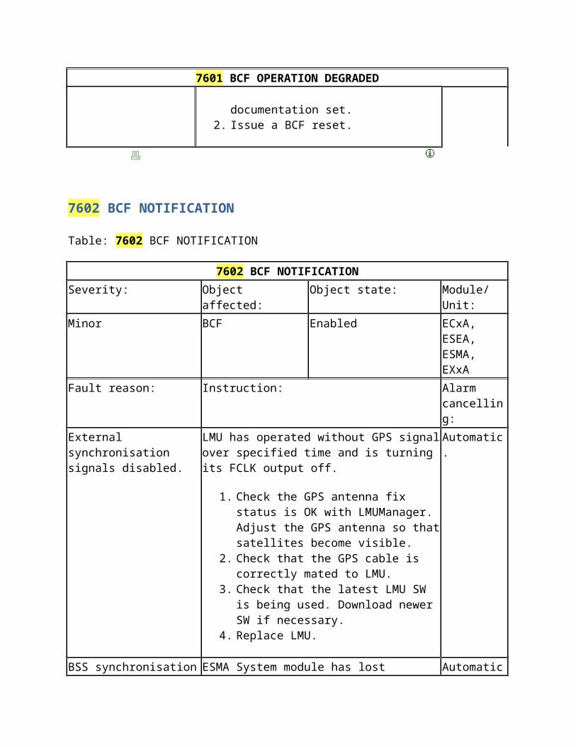
7607 TRX OPERATION DEGRADED
of antenna settings in the Site Commissioning file.
EXxx TRX module cooling fan(s) report no rotation.
One or more fans of the EXxx TRX module are not rotating. There is a danger of overheating.
1. Check that the fan unit cable is correctly mated to EXxx.
2. Check that there are no obstacles preventing the fan(s) from rotating.
3. Clean the fan unit of dust and/or dirt.4. Replace the fan unit.5. Replace EXxx.
Automatic.
One amplifier stage of Rx LNA Path A is broken in ERxx DDU module.
One of the two low noise amplifiers in balanced stage failed in Path A of ERxx DDU module.
1. Replace ERxx.
Automatic.
One amplifier stage of Rx LNA Path B is broken in ERxx DDU module.
One of the two low noise amplifiers in balanced stage failed in Path B of ERxx DDU module.
1. Replace ERxx.
Automatic.
Current used by MHA is out of range for ERxx DDU module (antenna A bypassed).
Measured current consumption of Mast Head Amplifier has exceeded min or max threshold indicating broken amplifier. MHA is using its bypass circuit and antenna feeder cable loss is not compensated.
1. Check that the current min/max limits and MHA settings correspond to the actual configuration.
2. Check the antenna line for any damage affecting the current supply to the MHA.
3. Replace MHA.4. Replace ERxx.
Manual.
Current used by MHA is out of
Measured current consumption of Mast Head Amplifier has exceeded min or max
Manual.
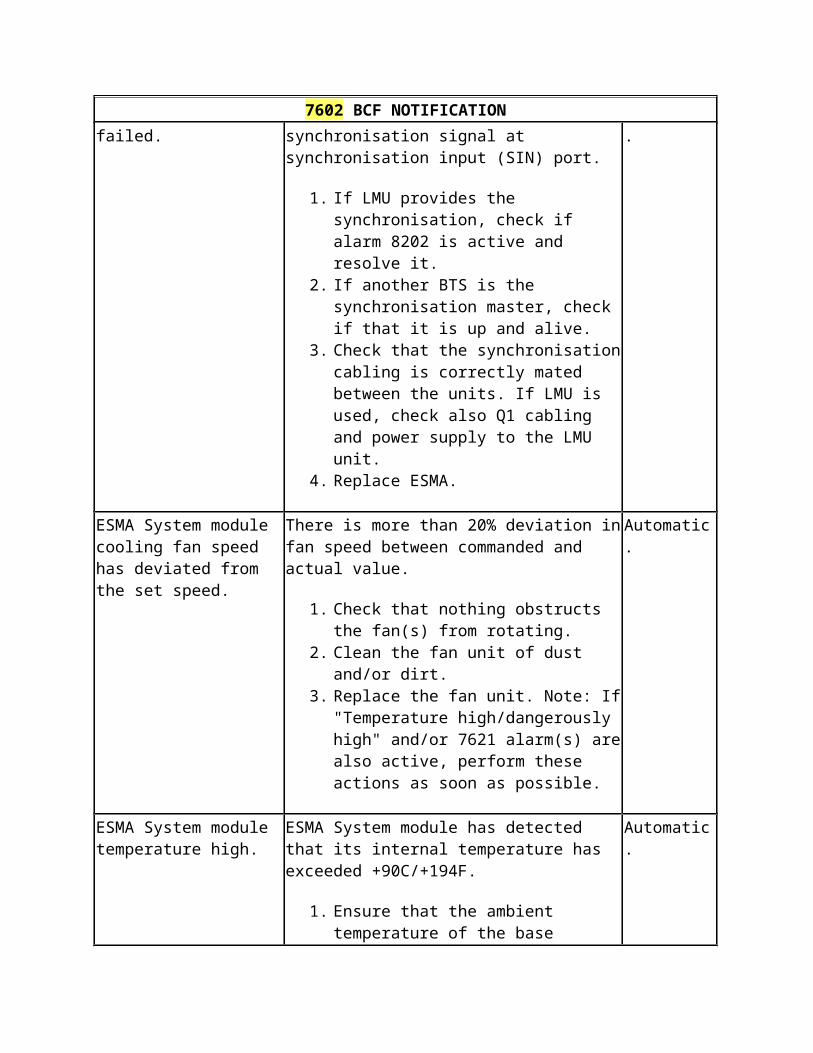
7607 TRX OPERATION DEGRADED
range for ERxx DDU module (antenna B bypassed).
threshold indicating broken amplifier. MHA is using its bypass circuit and antenna feeder cable loss is not compensated.
1. Check that the current min/max limits and MHA settings correspond to the actual configuration.
2. Check the antenna line for any damage affecting the current supply to the MHA.
3. Replace MHA.4. Replace ERxx.
ERxx DDU module SW upgrade failed.
SW upgrade is aborted due to negative acknowledgement from ERxx DDU module during sw download.
1. Issue a HW reset to ESMA.2. If the alarm persists, replace ERxx.
Manual.
ECxx RTC module cavity tuning synthesizer faulty. Tuning is only predicted.
The cavities are not fine tuned. ECxx RTC module tries to fine tune the cavities periodically. After successful fine tuning the alarm is cancelled.
1. Issue a sector lock/unlock to allow ECxx reconfiguration.
2. Replace ECxx.
Automatic.
Current used by MHA is out of range for ECxx RTC module (antenna B bypassed).
Measured current consumption of Mast Head Amplifier has exceeded min or max threshold indicating broken amplifier. MHA is using its bypass circuit and antenna feeder cable loss is not compensated.
1. Check that the current min/max limits and MHA settings correspond to the actual configuration.
2. Check the antenna line for any damage affecting the current supply to the MHA.
3. Replace MHA.4. Replace ECxx.
Manual.
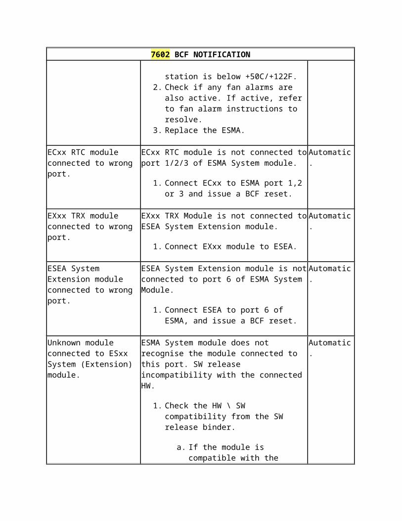
7607 TRX OPERATION DEGRADED
One amplifier stage of Rx LNA Path A is broken in ECxx RTC module.
One of the two low noise amplifiers in balanced stage failed in Path A of ECxx RTC module.
1. Replace ECxx.
Automatic.
One amplifier stage of Rx LNA Path B is broken in ECxx RTC module.
One of the two low noise amplifiers in balanced stage failed in Path B of ECxx RTC module.
1. Replace ECxx.
Automatic.
Commissioning file climate control profile mismatch, no fans detected.
Climate control profile indicates an installed fan unit but it is missing from the actual configuration. There is a danger of overheating.
1. If none of the modules at the site require fan units, change the fan profile to "No Fans" in the SCF and re-commission the site.
2. Check that the fan unit cable is correctly mated to EXxx.
3. Replace the fan unit.4. Replace the EXxx.
Conditional.
Can only be automatically cancelled when Site is commissioned with "no fans climate control profile".
Current used by MHA is out of range for ECxx RTC module (antenna A bypassed).
Measured current consumption of Mast Head Amplifier has exceeded min or max threshold indicating broken amplifier. MHA is using its bypass circuit and antenna feeder cable loss is not compensated.
1. Check that the current min/max limits and MHA settings correspond to the actual configuration.
2. Check the antenna line for any damage affecting the current supply to the MHA.
3. Replace MHA.4. Replace ECxx.
Manual.
EXxx TRX module Tx power is at least 3dB less than
Tx output power is over 3 dB lower than expected at Digital Power Control circuit
Manual.
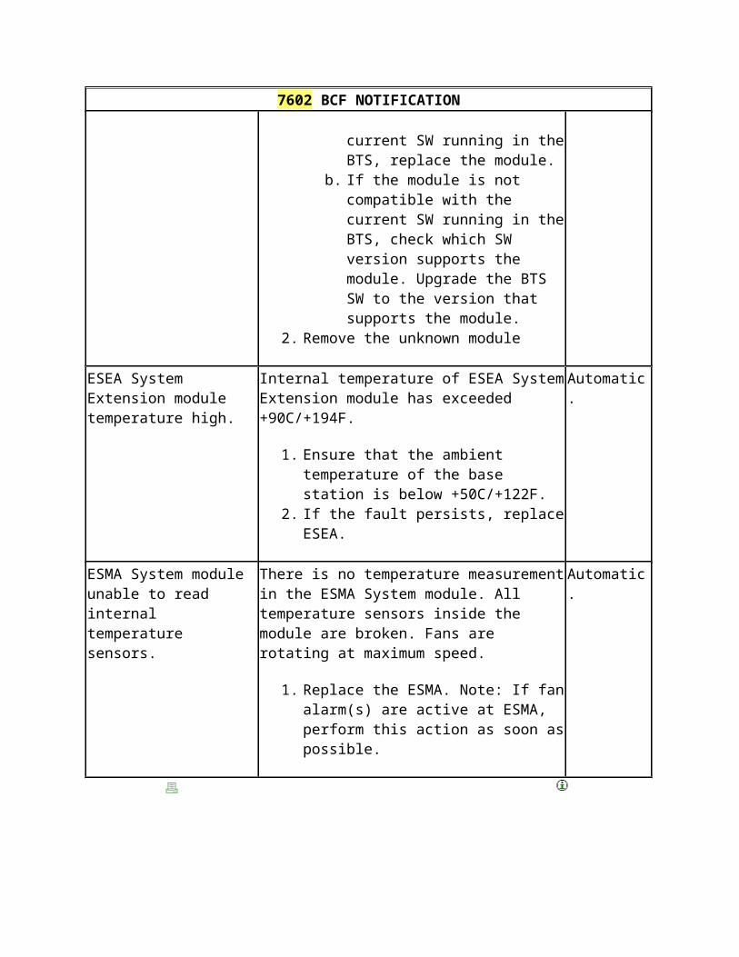
7607 TRX OPERATION DEGRADED
expected at DPC. block in EXxx TRX module.
1. Reset TRX/Sector.2. Replace EXxx.
EXxx TRX module detected only one Rx signal during RF cable autodetection.
RF cable autodetection found Rx signal missing from the sector where Rx diversity is being used.
1. Check that the Rx cabling between EXxx and ERxx are correctly mated. Check the condition of cables and connectors. Issue a sector reset.
2. Recommission the site with manual cabling, if Rx diversity is not to be used.
3. Replace ERxx.4. Replace EXxx.
Manual.
RF cable autodetection found mixed (bypass/2-/4-way) Tx combining in a sector.
During RF cable autodetection, Tx combining is found to be imbalanced. The Rx measurement value differences between any of the two carriers in the sector is more than 2.5 dB.
1. Check that the ERxx has equal number of EWxx modules in both Tx paths in 2-/4-way combined configuration. Issue a sector reset.
2. Check that the Tx cabling is correctly mated between units. Check the condition of cables and connectors. Issue a sector reset.
3. Replace EWxx.4. Replace EXxx.5. Replace ERxx.
Manual.
RSSI detected Rx signal difference exceeding threshold.
The difference limit of Received Signal Strength Indicator measurement has exceeded between the main and diversity antennas.
1. Check RSSI results with BTS Manager which antenna appears to
Automatic.
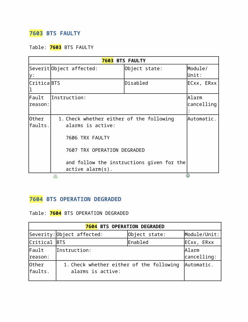
7607 TRX OPERATION DEGRADED
have abnormal values. If abnormal values are lower than values from other antennas, it indicates a disconnected or faulty cable in the loop or a faulty LNA. If abnormal values are higher than values from other antennas, it indicates interference coming outside of the BTS or a faulty cable/module.
2. Check the RF cables and connections.3. Check that the RXDL parameter at
the BSC is set to a reasonable value, taking into account the site condition in order to prevent unnecessary alarms.
4. Check and measure the antenna lines. 5. Check the antenna alignment.6. Replace ERxx. 7. Replace EXxx.
TRX objects of an EXxx TRX module are illegally split between 2 sectors.
TRX objects of one EXxx module are split into two different sectors when Rx diversity is in use.
1. Revise the RF cabling according to the actual configuration required (SCF/BSC). Issue a BCF reset to allow restart of RF cable autodetection.
2. If the target is to split TRX objects across sectors, perform recommissioning and manually specify the cabling including the split.
Automatic.
ERxx DDU module has detected VSWR above minor limit at antenna A.
User definable minor alarm treshold for VSWR measurement has been exceeded. The default value is 2.1.
1. Check the condition of the feeder and jumper cable, their connectors, sockets and connector seals starting from BTS end and proceed towards the antenna end. Replace damaged
Automatic.
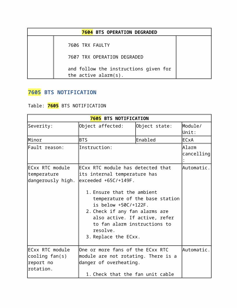
7607 TRX OPERATION DEGRADED
feeder cable. 2. If MHA is used, check that it is of
correct (sub)band. 3. With external test equipment,
measure the Return loss/VSWR of the antenna line. Perform step 1 again, if the measurement result is higher than expected.
4. Revise the VSWR alarm threshold by appending the commissioning.
5. Replace ERxx.
ERxx DDU module has detected VSWR above minor limit at antenna B.
User definable minor alarm threshold for VSWR measurement has been exceeded. The default value is 2.1.
1. Check the condition of the feeder and jumper cable, their connectors, sockets and connector seals starting from BTS end and proceed towards the antenna end. Replace damaged feeder cable.
2. If MHA is used, check that it is of correct (sub)band.
3. With external test equipment, measure the Return loss/VSWR of the antenna line. Perform step 1 again, if the measurement result is higher than expected.
4. Revise the VSWR alarm threshold by appending the commissioning.
5. Replace ERxx.
Automatic.
ECxx RTC module has detected VSWR above minor limit at antenna.
User definable minor alarm threshold for VSWR measurement has been exceeded. The default value is 2.1.
1. Check the condition of the feeder and jumper cable, their connectors, sockets and connector seals starting from BTS end and proceed towards the antenna end. Replace damaged feeder cable.
Automatic.
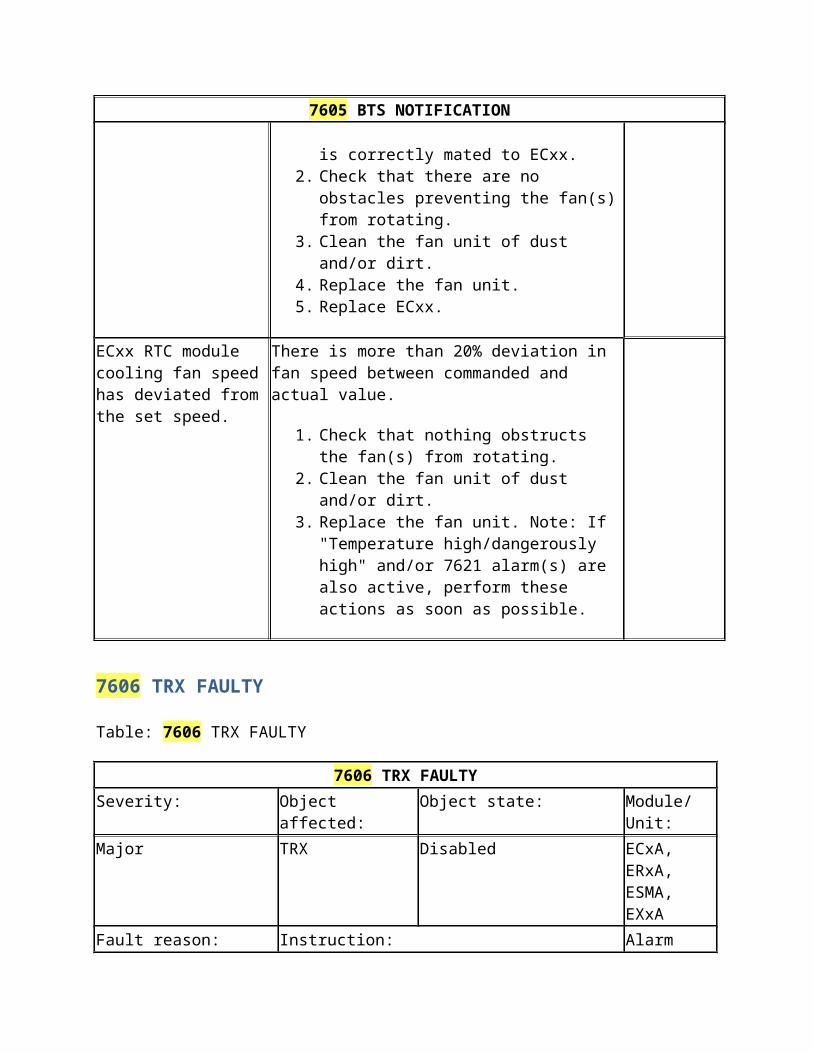
7607 TRX OPERATION DEGRADED
2. If MHA is used, check that it is of correct (sub)band.
3. With external test equipment, measure the Return loss/VSWR of the antenna line. Perform step 1 again, if the measurement result is higher than expected.
4. Revise the VSWR alarm threshold by appending the commissioning.
5. Replace ECxx.
7616 OSCILLATOR ADJUSTMENT TEMPORARILY INTERRUPTED
Table: 7616 OSCILLATOR ADJUSTMENT TEMPORARILY INTERRUPTED
7616 OSCILLATOR ADJUSTMENT TEMPORARILY INTERRUPTED
Severity: Object affected: Object state: Module/Unit:
Minor BCF Enabled ESMA
Fault reason: Instruction: Alarm cancelling:
Clock tuning DAC word reaching min/max limit.
Oven oscillator DAC word is within 5% of the min/max limit. Alarm is activated if the DAC word is between 0-204 or 3891-4095. This alarm can be activated due to incorrect synchronisation settings in transmission network.
1. Check the Abis synchronisation that there are valid Rx clock sources available.
a. If the reference clock is ok, tune the ESMA clock to the correct frequency.
b. If the reference clock is not ok, check the alarm history for 8xxx alarms for the possible reason for the incorrect reference clock. Follow the instructions on 8xxx alarms. After correcting the reference clock tune ESMA clock to the correct frequency.
Automatic.
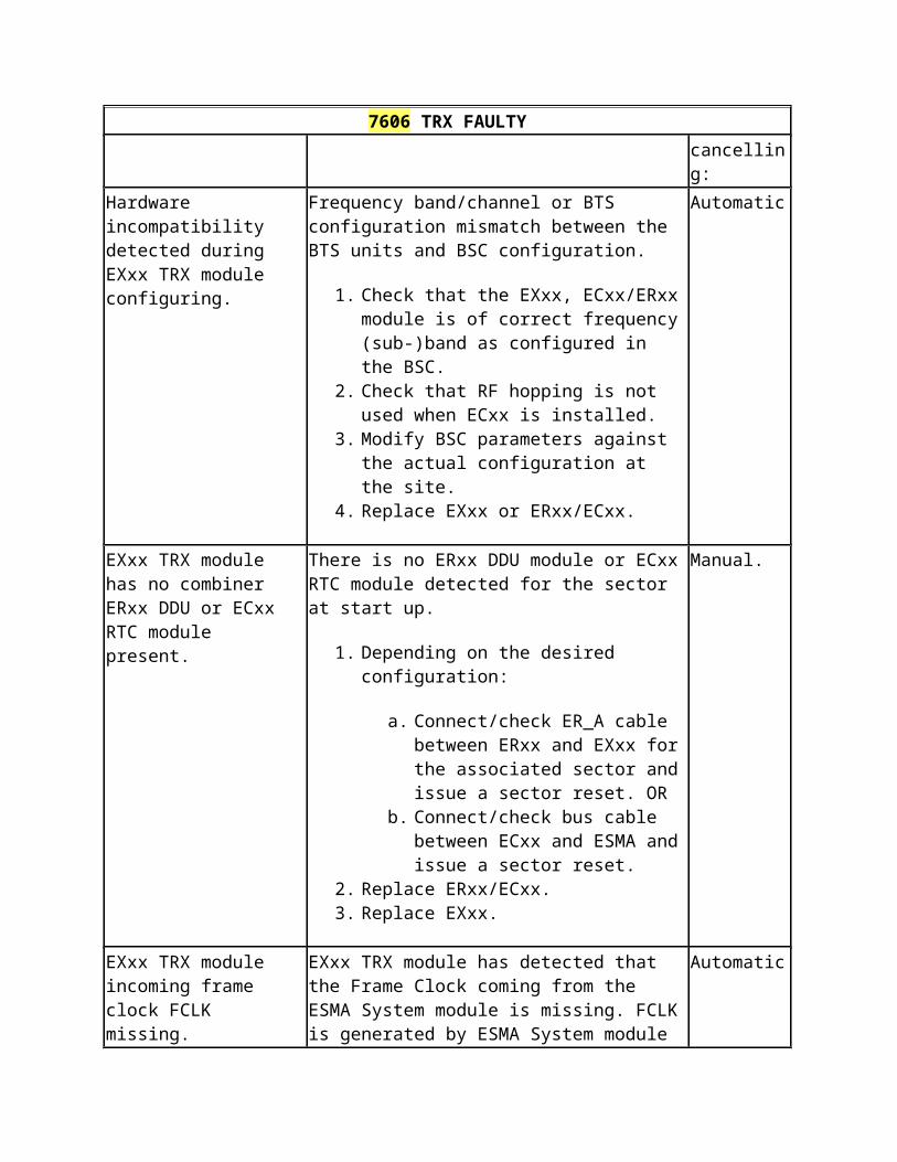
8099 Error rate > 1 E-3
Table: 8099 Error rate > 1 E-3
8099 Error rate > 1 E-3
Severity: Object affected: Object state: Module/Unit:
Critical TRE ESMA
Fault reason:
Instruction: Alarm cancelling:
Field not used.
Received signal has degraded on E1/T1 interface. Bit Error Ratio (BER) is over 1E-3.
1. If FIFA PIU is used, Refer to the FIFA product documentation for instructions.
2. Check that the interface settings are correct for the link.3. Check quality of the E1/T1 line by enabling a Loop to
Interface (line) at the far end equipment. If the alarm is cancelled during the loop test, check the far-end equipment.
4. Equip an external cable loop to the interface to check that the interface in FIxx is ok. If the alarm is still active during the loop test, go to step 6.
5. Check the condition of cables, connectors and correct polarities of the wire pairs.
6. Check that FIxx is fully inserted in to ESMA.7. Replace FIxx.8. Check the signal quality of the transmission path to the
alarming equipment.
Automatic.
8102 Error rate > 1 E-6
Table: 8102 Error rate > 1 E-6
8102 Error rate > 1 E-6
Severity: Object affected: Object state: Module/Unit:
Major TRE Enabled ESMA
Fault reason:
Instruction: Alarm cancelling:
Field not used.
Received signal has degraded on E1/T1 interface. Bit Error Ratio (BER) is over 1E-6.
1. If FIFA PIU is used, Refer to the FIFA product documentation
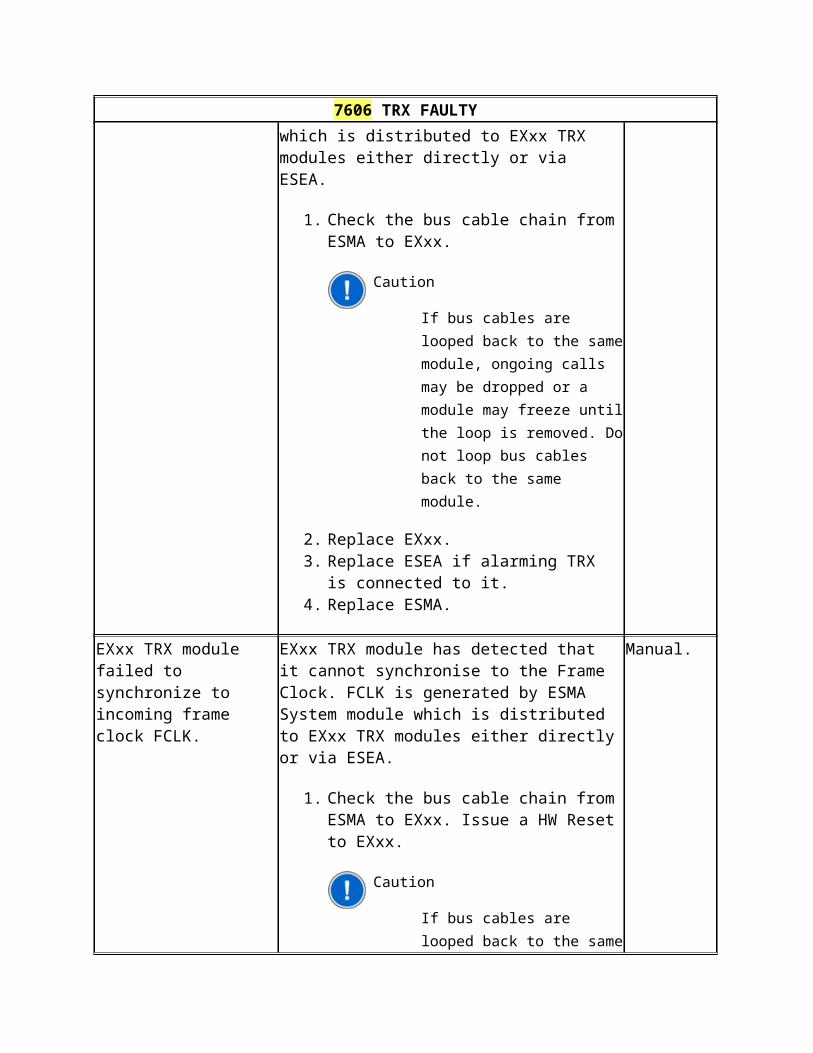
8102 Error rate > 1 E-6
for instructions.2. Check that the interface settings are correct for the link.3. Check quality of the E1/T1 line by enabling a Loop to
Interface (line) at the far end equipment. If the alarm is cancelled during the loop test, check the far-end equipment.
4. Equip an external cable loop to the interface to check that the interface in FIxx is ok. If the alarm is still active during the loop test, go to step 6.
5. Check the condition of cables, connectors and correct polarities of the wire pairs.
6. Check that FIxx is fully inserted in to ESMA.7. Replace FIxx.8. Check the signal quality of the transmission path to the
alarming equipment.
8112 Frequency error
Table: 8112 Frequency error
8112 Frequency error
Severity: Object affected: Object state: Module/Unit:
Minor TRE Enabled ESMA
Fault reason:
Instruction: Alarm cancelling:

8112 Frequency error
Field not used.
The node is running on the internal clock as configured in the timing priority list. This alarm can also be raised in case synchronisation protection is configured, when the Rx source signals from both directions have its MCBs in state '1' .
1. Check that synchronisation priority list has Rx clock entries for used interfaces.
2. In case FIFA PIU is used, check that the microwave link is commissioned and operational. Refer to FIFA product documentation for further instructions.
3. If any of the alarms 8050, 8066, 8081, 8099, 8056 or 8073 are active, follow the instructions on them.
4. Check that interface cables are correctly mated to FIxx. Check also condition of the connectors.
5. If BTS is part of Nokia PDH loop protection configuration, check MCB/LCB configuration and operational state of loop network.
Automatic.
8125 Loss of synchronization signal (s)
Table: 8125 Loss of synchronization signal (s)
8125 Loss of synchronization signal (s)
Severity: Object affected: Object state: Module/Unit:
Critical TRE Enabled ESMA
Fault reason:
Instruction: Alarm cancelling:
Field not used.
All defined synchronisation sources in the synchronisation priority list are invalid or the list is empty. Node is running on its internal clock.
1. Check that synchronisation priority list has Rx clock entries for used interfaces.
2. In case FIFA PIU is used, check that the microwave link is commissioned and operational. Refer to FIFA product documentation for further instructions.
3. If any of the alarms 8050, 8066, 8081, 8099, 8056 or 8073 are active, follow the instructions on them.
4. Check that interface cables are correctly mated to FIxx. Check also condition of the connectors.
5. Replace FIxx.
Automatic.
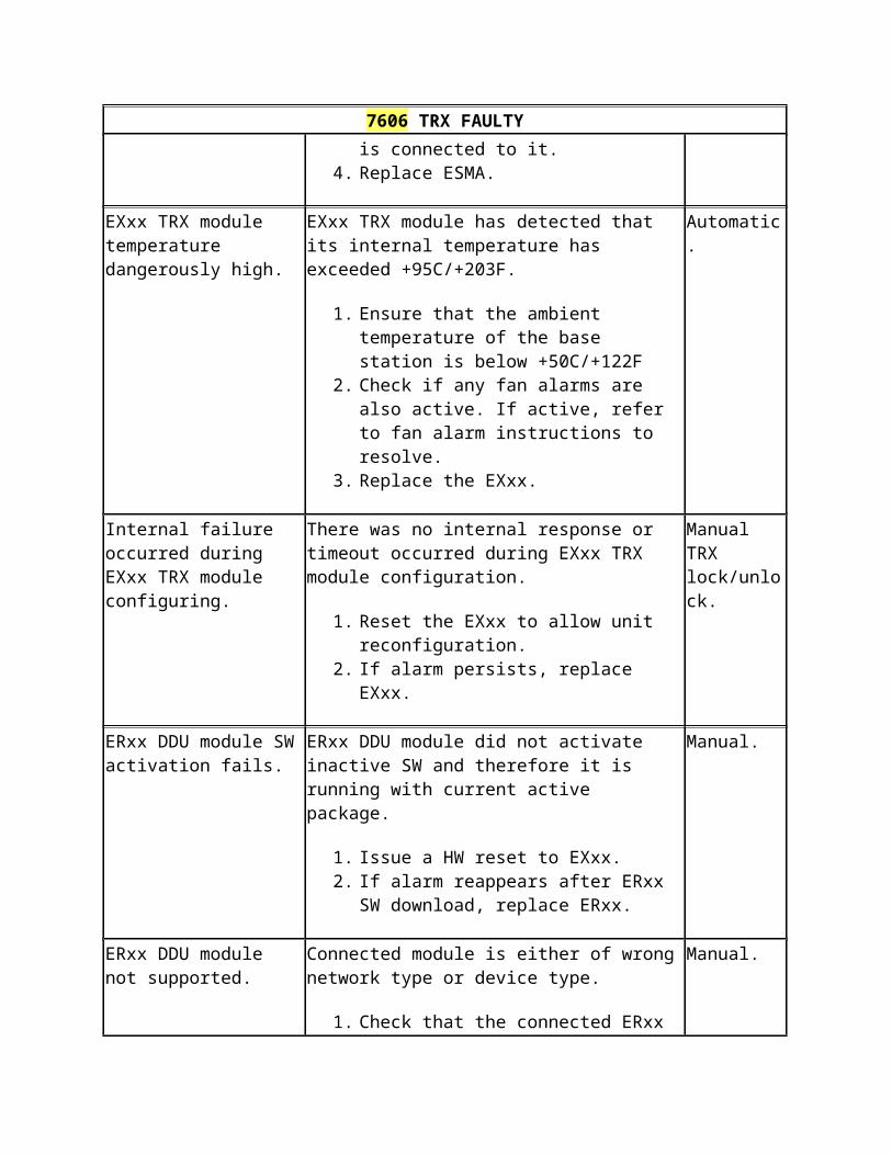
8125 Loss of synchronization signal (s)
8148 Equipment reset
Table: 8148 Equipment reset
8148 Equipment reset
Severity: Object affected: Object state: Module/Unit:
Warning TRE Enabled ESMA
Fault reason:
Instruction: Alarm cancelling:
Field not used.
This warning is issued by Q1 device when reset has occurred.
1. Find out the alarming Q1 device and refer to its product documentation for more details on this warning message.
This is a warning and no cancellation se
8165 Real time lost fault
Table: 8165 Real time lost fault
8165 Real time lost fault
Severity: Object affected: Object state: Module/Unit:
Major TRE Enabled ESMA
Fault reason:
Instruction: Alarm cancelling:
Field not used.
Q1 device has not received real time from the polling master (BTS/BSC). Time stamps are not displayed correctly.
1. Find out the alarming Q1 device and refer to its product documentation for more details on this alarm.
Automatic.
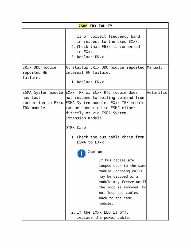
8020 Blocked from use
Table: 8020 Blocked from use
8020 Blocked from use
Severity: Object affected: Object state: Module/Unit:
Major TRE Enabled ESMA
Fault reason:
Instruction: Alarm cancelling:
Field not used.
A cross-connection is configured to an interface which is not in use.
1. Check that all interfaces where cross connection termination points have been set are in use. In cross connection window, blocked cross connections are highlighted in Italic font.
2. Remove any unnecessary cross connections that have termination point(s) to non-existing or unused interfaces.
Automatic.
8066 AIS 2 M
Table: 8066 AIS 2 M
8066 AIS 2 M
Severity: Object affected: Object state: Module/Unit:
Major TRE Enabled ESMA
Fault reason:
Instruction: Alarm cancelling:
Field not used.
The signal is cut, deteriorated or a equipment loop is set in the far-end equipment. Alarm Indication Signal (AIS) is indicated as "1111 1111" in all received time slots.
1. Check the transmission path to find where AIS insertion occurs.
2. Check the alarms at the far-end. Refer to the product documentation of the far-end equipment.
3. In case FIFA PIU is used, check that the microwave link is commissioned and operational. Check that 2M cross connections are configured at FIFA. Refer to the FIFA product documentation for further instructions.
Automatic.
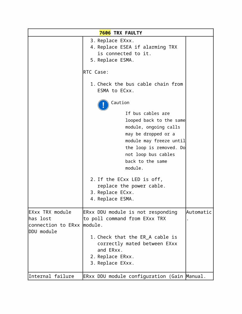
8066 AIS 2 M
4. Replace FIxx.
8081 Loss of frame alignment
Table: 8081 Loss of frame alignment
8081 Loss of frame alignment
Severity: Object affected: Object state: Module/Unit:
Critical TRE Enabled ESMA
Fault reason:
Instruction: Alarm cancelling:
Field not used.
Framing error has been detected in the received signal. This alarm can be caused by bad quality of the E1/T1 signal or the device at the far-end is not sending valid E1/T1 signal due to misconfiguration.
1. If FIFA PIU is used, Refer to the FIFA product documentation for instructions.
2. Check that the interface settings are correct for the link.3. Check quality of the E1/T1 line by enabling a Loop to
Interface (line) at the far end equipment. If the alarm is cancelled during the loop test, check the far-end equipment.
4. Equip an external cable loop to the interface to check that the interface in FIxx is ok. If the alarm is still active during the loop test, go to step 6.
5. Check the condition of cables, connectors and correct polarities of the wire pairs.
6. Check that FIxx is fully inserted in to ESMA.7. Replace FIxx.8. Check the signal quality of the transmission path to the
alarming equipment.
Automatic.
8179 Far-end alarm
Table: 8179 Far-end alarm
8179 Far-end alarm
Severity: Object affected: Object state: Module/Unit:
Major TRE Enabled ESMA
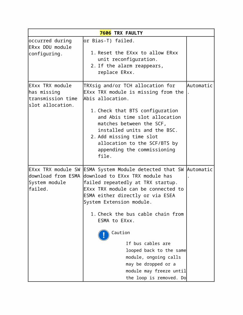
8179 Far-end alarm
Fault reason:
Instruction: Alarm cancelling:
Field not used.
Sent by the equipment in the far-end (TS0 Bit 3), which indicates that far-end equipment is unable to receive the signal.
1. Check the far end equipment for alarms 8050, 8066, 8081 and 8086. See the instructions on them.
2. Apply Loop to interface (line) at far end to check that link is ok. If 8050/8066/8081/8086 alarm is not active at near-end during the loop test the problem is at the far-end receiver. Note: 8179 Far-end alarm will be cancelled during this test.
3. Equip an external cable loop to the interface to check that the interface in FIxx is ok. If 8050/8066/8081/8086 alarm is active during the loop test, go to step 5. Note: 8179 Far-end alarm will be cancelled during this test.
4. Check the condition of cables, connectors and correct polarities of the wire pairs.
5. Check that FIxx is fully inserted in to ESMA.6. Replace FIxx.
Automatic.
8050 Loss of incoming 2 M signal
Table: 8050 Loss of incoming 2 M signal
8050 Loss of incoming 2 M signal
Severity: Object affected: Object state: Module/Unit:
Critical TRE Enabled ESMA
Fault reason:
Instruction: Alarm cancelling:
Field not used.
FIxx PIU has detected no incoming signal on E1 interface. Far End Alarm bit indication (TS0/b3) is sent in Tx direction.
1. Check that interface settings are the same at both ends of the link.
2. Check that the E1 cable is connected to right interface and cable is correctly mated to the PIU. Check the condition of cables, connectors and in case FIPA is used, check the correct polarities of the wire pairs.
3. Replace FIxx
Automatic.