nox emissions of diesel engines according to … · nox emissions of diesel engines according to...
TRANSCRIPT
;;zt;;o -vooy {~Jet{.)
NOx EMISSIONS OF DIESEL ENGINES
ACCORDING TO MARPOL 73/78, ANNEX VI
Standard for Certification No. 2.15
FEBRUARY 2001
DBT NORSKE \'ERITAS AS BD3LlOTEKET
DET NORSKE VERITAS

STANDARD FOR CERTIFICATION
No. 2.15
NOX EMISSIONS OF DIESEL ENGINES ACCORDING TO MARPOL 73/78, ANNEX VI
FEBRUARY 2001
DET N ORSKE VERITAS Veritasveien 1, N- 1322 Hl!lvik, Norway Tel.: +47 67 57 99 00 Fax: +47 67 57 99 11
FOREWORD
DET NORSKE VERITAS is an autonomous and independent Foundation with the objective of safeguarding life, property and the environment at sea and ashore.
DET NORSKE VERITAS AS is a fully owned .subsidiary Society of the Foundation. IL undertakes classification and certification of ships, mobile offshore units, fixed offshore structures, facilities and systems fo r shipping and other industries. The Society also carries out research and development associaced with these fu nctions.
DET NORSKE VERITAS operates a worldwide network of survey stations and is authorised by more than 120 national. administrations to carry out surveys and, in most cases, issue certificates on their behalf.
Standards for Certification
Standards for Certification (previously Certification Notes) are publications that contain principles, acceptance criteria and practical information related to the Society's consideration of objects, personnel, organisations, services and operations. Standards for Certification also apply as the basis for the issue of certificate.~ and/or declarations that may not necessarily be related to classification.
A list of Standards for Certification is found in the latest edition of the Introduction booklet:-; to the "Rules for Classification of Ships", the "Rules for Classification of Mobile Offshore Units" and the "Rules for Classification of High Speed, Lighl Craft and Naval Surface Craft". In "Rules for Cla'isitication of Fixed Offshore lnst.allations", only those Standards for Certification that are relevant for this type of structure, have been listed.
The list of Standards for Certification is also included in the current "Classification Services - Publications" issued by the Society, which is available on request. All publications may be ordered from the Society's Web site http://exchangc.dnv.com.
'1J Det Norske Vcritas Printed in Norway by CGS AS
If any person suffers loss or damage which is proved to have been caused by any negligent act or omission of Det Norske Veritas. t hen Det Norske Veritas shall pay compensation to such person for his proved direct loss or damage. However. tfic comp1msation shall not exceed an amount equal to tf!n times tho fee charged for the service in question, provided that the maximum compensation shllll never exceed USO 2 million.
In this provision " Det Norske Ver itas·· shall mean the Foundation Det Norske Voritas as well as all its ~ubsidiaries. directors. officers. f!mployees. agents and any other :icting on behalf of Oet Norska Veritas.
CONTENTS
1. Preamble ................................................................... 4 4.3 Measurement equipment ....... ..................................... 7 2. Gencra1 ...................................................................... 4 4.4 Test run ....................................................................... 7 2.1 DNV' s scope of work ................................................ 4 4.5 Component and engine setting verification ................ 8 2.2 Application ................................................................. 4 5. Reporting and issue of statemt!nt of' compliance .... 8 2.3 Plans and particulars .................................................. 5 5.1 Tc.-;t report .................................................................. 8 3. Engine families or engine groups ............................ 6 6. Appendix I · specification of exhaust gas analysers9 3.1 General ....................................................................... 6 6.1 General .... ........ ........................................................... 9 3.2 Basic division of engine families/groups ................... 6 6.2 Analysers .................................................................... 9 3.3 Selection of Parent Engine ......................................... 6 7. Appendix II· calibration of analytical instruments 4. Emission test ............................................................. 6 (engine parameters) ................................................ 10 4.1 General. .. ............ ........................................................ 6 7. 1 General ...... ....................... ........................................ 10 4.2 Test conditions ...................... ..................................... 6
D ET NORSKE VERITAS
4
1. Preamble Jn September 1997, Annex VI to MARPOL 73178 was adopted by TMO. The annex in question takes into consideraLion the emi.s.sion.s of harmful substances to air from ships.
Annex VI had not come into force at !he time of writing th.is Standard for Certification, and will not come into force until at least 15 states, representing at least 50 % of the world merchant tleel lOnnage have ratified it. Engine manufacturers, shipyards and s hip owners are already requesting NOx emission certification of diesel engines based on MARPOL, Annex VI, Reg. 13. The urgency, concerning emission certification of diesel e ngine emissions of NOx, is due to a retroactive clause in Regulation 13 of Annex VI. This clause states that, regardless of when Annex Vl comes in\.O force, the NOx emission certification requirement will apply for almost all diesel engines, installed in ships whose keel was laid on, or after 1st of January 2000.
The requirements for NOx emissions are detailed in the "Technical code on control of emission of nitrogen oxides from diesel engines" (hereinafter referred to as "th.~ Code") adopted by Res. 2 of the 1997 M ARPOL conference.
This Standard for Certification describes how DNV certifies diesel eng.ines in accordance with MARPOL, Annex VI, before this Annex comes into force.
2. General
2.1 DNV's scopt! of work If requested, DNV may issue a Statement of compliance (Interim Engine Air Pollution Prevention Certificate) for a diesel engine that is to be installed onboard a ship above 400 tons gross tonnage or on board a fixed or tJoating offshore platform or drilling tig.
Before issuing a Statement of compliance, DNV shall have collected documentation and verified Ule compliance with UlC Code. Unless an engine of the pa11icular model have been successful I y tested earlier, an engine eruission lest shall be arranged and witnessed by DNV.
The request to issue a Statement or compliance must come from engine manufacturer/designer, shipyar.d or owner.
If requested ON V may issue statements of compliance for engines regard less of class.
It is imperative Urnt DNV. bet'orc issue of any statement, have received confirmation from the responsible flag state thaL a Stateruenl of compliance issued by DNV wili be accepted when Annex V l comes into force, hcfore issue of any statement. II' it is not possible to obtain such confirmation, the shipyard/owner must be made aware that there is a risk that a DNY Statement of compliance may not be accepted by the Hag State.
Standard for Certification- No. 2.15
February 2001
A DNV St.atement of compliance shall certify that the engines comply with all requirements of the Code so that the Statement of compliance may be replaced by an Engine lnternalional Air Pollution Prevention Certificate, issued by the Hag state or by DNV on behalf of the flag state, when Annex VT comes into force.
2.2 Application The emission certification requirements, diesel engines, of Annex VI app ly to;
1) Each die.sci engine with a power output of more than 130 kW that is in~talled on a ship above 400 terns gross tonnage, a fixed or. floating offshore platform or drilling rig, keel laid on or after 1st of January 2000.
2) Each diesel engine with a power output of more than 130 kW, installed in a ship above 400 terns gross tolUlage, a fixed or 1loating offshore platform or drilling rig, which undergoes a major conversion* on or after I st of January 2000.
T he emission certification requirements, diesel engines, of Annex Vl do not apply to;
1) Emergency diesel engines and engines installed in lifeboats and any device or equipment intended to be used solely in case of emergency, e.g. diesel engine solely used for emergency fire-fighting pump drive.
* By major conven;ion means a modification of a diesel engine where;
- the engine is rep[a<.;ed by a new engine built on or after lst of January 2000, or
- any substantial modification, see 1.3.2 of the Cotle, ii. made to the engine, or
• the maximum continuous rating of the engine is increased by more than 10 %.
Note The NOx emission requirements of MAR POL, Annex VI concerns diesel engines only. I.e. NOx emissions frorn gas turbines, boilers etc. are not considered.
Note When DNV carries out work in accordance with MARPOL, Annex VI and the NOx Technical Code, it is on behalf of a nag state. I lenee DNV can neither allow exceptions from tl1c Code nor interpret the Code freely or apply the principle of equivalcncy. Auy deviation can only be ncceptccl by the !lag state and not by Lhe third party verifier, i.e. DNV.
Based upon the requirements of the Code with respect lo documentation and testing, it shall be shown lhat the emission of ni!J'ogcn oxides (calculated as the total weighted mean value) from the engine is below the following limits:
1) Engine speed, n, less than 130 r.p.m.: 17.0 g/kWh 2) Engine speed, n, between 130 r.p.m. - 2000 r.p.m.:
45 x n-0.z g/kWh
3) Engine speed, n, 2000 r.p.m. and above: 9.8 g/kWh
Depending on the application, the NOx emission level of the diesel engine shall be determined and a weight.e<l mean value of lhc emission level shall be calculated according to one or the following test cycles:
DETNOR.SKE VERlTAS
Standard for Certification· No. 2.15
.February 2001
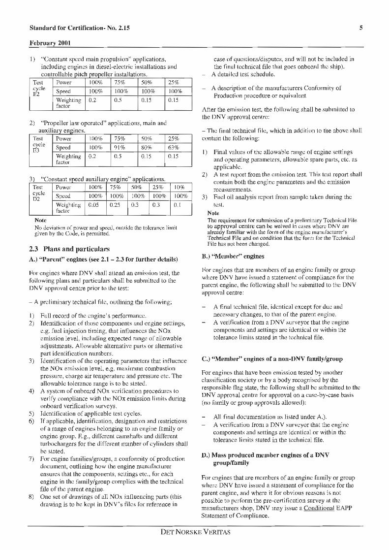
1) "Constant speed main propulsion" applications, including engines in diesel-electric insLallations and
llabl contro e pitch propeller installations. Test Power 100% 75% 50% 25% cycle Speed 100% 100% 100% 100% E2
Weighting faclor
0.2 0.5 0.15 0.15
2) "Propeller law operated" applications, main and T . aux1 rnry engines.
Te~l Power 100% 75% 50% 25% cycle Speed 100% 91% 80% 63% m
Weighting 0.2 0.5 0.15 0.15 factor
3) "C onstant soee d auxiliary engine" aDolications. Test Power 100% 75% 50% 25% 10% cycle Speed 100% 100% 100% 100% 100% D2
Weighting factor
0.05 0.25 0.3 0.3 0.l
Note No deviation of power and spccc.l, outside the tolerance limit given by the Co<li; is permitted.
2.3 Plans and particulars A.) "I1arcnt" engines (see 2.1 - 2.3 ror further details)
t-lor engines where DN V shall attend an emission test, the following plans and particulars shall be submitted lo the DNV approval centre prior to the Lest:
- A preliminary technical file, outlining the following;
I ) Full record of the engine's perlormance. 2) Identification of those components and engine settings,
e.g. fuel injection timing, that influences the NOx emission level, including expected range of allowable adjustments. Allowable alternative parts or alternative part identification numbers.
3) Identification of the operating parameters that influence the NOx emission level, e.g. maximum combustion pressure, charge air temperature and pressure etc. The aliowable tolerance range is to be stated.
4) A system of onboard NOx verification procedures lo verify compliance with the NOx emission limits during onboard verification surveys.
5) Identification of applicable test cycles. 6) Tf applicable, identification, designution and restrictions
of a range of engines belonging to an engine family or engine group. E.g., different camshafts and different turbochargers for the different number of cylinders shall be stated.
7) For engine famil ies/groups, a conformity of production document, outlining how the engine manufacturer ensures lhat the components, settings etc., for each engine in the family/group complies with the technical file of the parent engine.
8) One set of drawings of all NOx inl1uencing parts (lhis drawing is to be kept in DNV' s files for reforence in
case of questions/disputes, and will not be included in the final technical file that goes onboard the ship).
- A detailed Lest schedule.
- A description of the manufaclurers Conformity of Production procedure or equivalent
After the emission test, the following shall be .~ubmitted to the DNV approval centre:
s
-The final technical fi le, which in addition lo the above shall contain lhe following:
I) Final value~ of the allowable range of engine settings and operating parameters, allowable spare parts, clc. as applicable.
2) A test report from the emission test. This test report shall contain both the engine parameters and the emission measurements.
3) Fuel oil analysis report from samp le taken during the tcsl.
Note The requiremcnl for submission of' 11 preliminary Technical J-iile lo approval centre can be waived in cases where DNV are alread¥ fam~Jiar witll Lhe fo~·'!' of the engine manufacturer's Technical File and on cond111on that the form for rhe Tcchni<.:al File has not heen changed.
B.) "Member" engines
J-lor engines that are members of an engine family or group where DNV have issued a statement of compliance for the parenl engine, the rollowing shall he submitted to the DNV approval centre:
A final technical file, identical except for due and necessary changes, to that or the parent engine. A verification from a DNV surveyor that the engine components and settings arc identical or within the tolerance limiL~ stated in the technical file.
C.) ''Member" engines of a non-UNV family/group
For enginc.o.; lhat have been emission tested by another cla.~sificalion society or hy a body recognised by the responsible tlag state, the following shall he submitted to the DNV approval centre for approval on a case-by-case basis (no family or group approvals allowed):
All final documentation a.o.; lisLed under A.). A verification from a DNV surveyor that the engine compone nts and settings are identical or within the tolerance limits stated in the technical file.
D.) Mass produced member engines of a DNV group/family
For engines that are members of an engine family or gruup where DNV have issued a statement of compliance for the parent engine, and where it for obvious reasons is not possible to perform the pre-certification survey at the manufacturers shop, DNY may issue a Conditional EAPP Statement of Compliance.
DET NORSKE VERITAS
6
For these engines, the EAPP Statement of Compliance will be val id first after the engines have been subject to preccrtiftcatlon survey in connection wilh e.g. the sea ui al. Jn this occasions the fo llowing shall be submitted to the D NV approval centre:
A final technical file, identical ex.cepl for due and necessary changes, to that of the parent engine.
Note It is of ulmost importance that in theses cases, Lht: huycr is awrue thnt !he engine or engines have only a ConditionaJ EAPP Statement of Compliance, and d1at the engine buyer will have LO arrange for Lhe prc-cc1tification survey.
3. Engine families or engine groups
3.1 General
T o avoid emission testing of each engine for compliance with the NOx emission limit, the Code allows thal engines are divided into families or groups and that only a "parent" engine of ea<.:h family or group is tested.
T he engine famil y concept may be applied to engines that arc series produced and that, after installation onboard, require no modification or adjustment'> that may adversely affect the NOx emission level.
T he engine group concept may he applied Lo engines that are produced for similar applications hut typically require minor modifications or adjustments <luring installation or in service onboard. These engines are typica lly larger engines for p ropulsion installations.
3.2 Basic division of engine families/groups
T o belong to an engine family or group, Lhc engine shall have Lhe same basic type designation, i.e. the engine shall be of Lhe same basic design with the same design of the NOx intluencing compo nents .
T he allowable differences in an engine group or family are then differences in number of cylinders, differences in rating and speed (i.e. di.tfercnl operating parameters), differences in engine settings (such as fuel injection timing) and of course also difference in co mponent design on the condition that the different designs are tested or similarly proved not lo increase the NOx emissions.
3.3 Selection of Parent Engine
The basic requirement when an engine manufacturer sel.ects a parent engine is that the parent engine shall have the highest NOx emission level of the engines within the group.
The following guideline.<; a~ provided in the Code for selection of a parent engine.
higher fuel deli very rate (if available from manufacturer) higher mean eftectivc prcs~ure higher maximum cylinder pressure higher charge air temperature and pressure earlier fuel injection Liming.
Standard for Certification- No. 2.15
.February 2001
Hence, in order to achieve all the negative (NOx-wise) adjustments in one engine, the engine manufacturer may have to adversely adjust the selected parent engine in order to have a "worst case engine".
Alternatively, tl1e engine manufacturer can carry out a parameter sensitivity survey where the different engine parameters influence on Lhe engine ' s NOx emission leve l i:> determined. T he records from !hi:; test c an then be used for determining the boundary limits for the engine famil y/group with respect to operating parameters and/or engine seltings.
4. Emission test
4.1 General Before issuing any statement of eompl iance for an engine, the engine itselJ or an engine of similar design must have heen tested according to the procedures outlined in the Code. Any deviation from these procedures must be accepted by DNV and the F lag State, p1ior to the emission test.
4.2 Test conditions
4.2.1 Ambient condition factor, fn
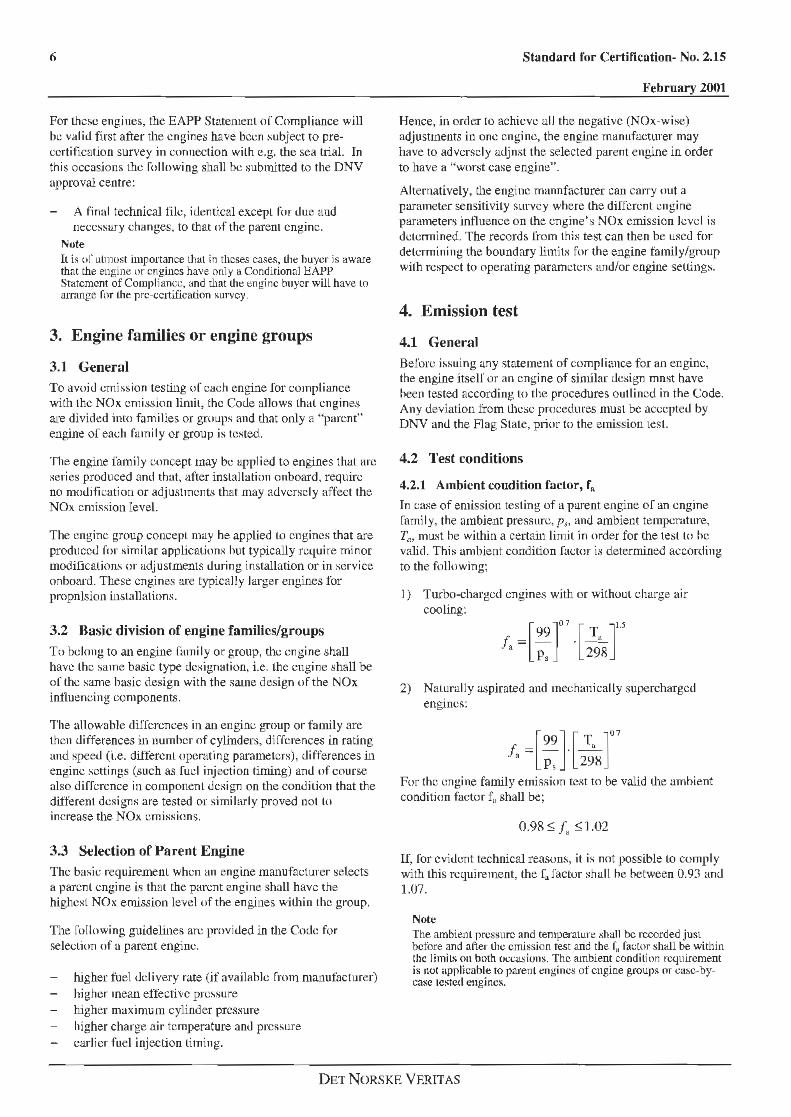
In case of emission testing of a parent engine of an engine family, the ambient pressure, p1 , and ambient temperature, Ta, must he within a certain limit in order for the test lo he valid. This ambient condition facto r is determined according to the followi ng;
I) T urbo-charged engines with or withouL c harge air cooling:
-[99)0
·
1
[ T11 ]i..s f,-- · --n Ps 298
2) Naturally aspirated and mechanically supercharged engines:
[99) [ T ]07
.f., == I\ . 2;8 For the engine family emission test to be valid Lhe ambient condi tion factor f11 shall be;
0.98 ~ !. ~ ·1 .02
If, for evident technical reasons, it is not possible Lo comply with this requirement, the 1~ factor shall he between 0. 93 and 1.07.
Note The ambienl pressure and temperature shall be recorded just before and after the emission test and the r. factor sh<ill be within the limits on both occasions. The ambient condition requirement i.s not applicable to parent engines of engine groups or casc-bycase tested engines.
DET NORSKE VF.RIT AS
Standard for Ce1·tification- No. 2.15
February 2001
4.2.2 Engines with charge air cooling
The temperature of the cooling medium and charge air shall be recorded. All engines must be capable of opemting below the NOx e mission limit when the ambient seawater temperature is 25°C. This capability must be shown by the engine manufacturer, preferably by running the test at maximum cooling medium temperature (alarm limit) and corresponding maximum charge air temperature. ft can also be shown hy running a parameter sensitivity test, i.e. by running a series of tests showing lhe NOx emission level's correlation to the charge ai r temperature.
4.2.3 Engine power
The basis for the emission measurement and calculation is uncorrected hrake power. Non-essential auxiliaries should not be mounted for the test, except as outlined in resolution 2, 5.2.3.2 and 5.2.3.3 of the NOx Technical Code.
4.2.4 Lubricating oil and cooling system
The engine fuel oil, lubricating oil and cooling water systems shall be operated within the "normal" operating values as specified by the engine manufacturer. The specification of the used lubricating oil shall be recorded.
4.2.S Test fuel
Unless otherwise agreed, a DM-grade marine fuel, !SO 82 17, 1996, with properties suitable for the engine type shall be used. The fuel temperature (viscosity), before the engine shall be according to U1e engine manufacturers recommendations and shall be recorded.
4.3 Measurement equipment
4.3.1 Exhaust gw; composition
The emission of gaseous components subject to testing shall be measured by analysers as specified in Appendix I of this Standard for Certification.
4.3.2 Engine parameters
An engine dynamomcter or alternator with adequate characteristics to perform testing after the specified test cycles shall he used.
The instrumentation shall have an accuracy at least as good as the values of maximum tolerances given in Appendix ll of this Standard for Certification.
If an alternator is used, the altcmator efficiency shall have hccn established.
The equipment for meaiwring the relevant engine parameters, e.g. temperature and pres.c;urc of exhaust gas, fuel oil, lubricating oil and cooling waler, shall fulfil the requirements with respect to accuracy and calibration as detailed in Appendix II of this Standard for Certification.
7
4.3.3 Exhaust gas flow
Since the NOx emission level is measured as parts per million (volume), ppmv, and the IMO limit is set as g/kWh, it is of utmost importance for the emission calculations that the exhaust gas flow is established accurately.
Three fundamentally different methods are allowed in the Code;
Direct measurement method. This method involves direct measurement of the exhaust gas flow by means of a venturi Oow nozzle or similar dev ice. The measurement shall be in accordance with a recognised international standard (none is explicitly mentioned in the Code).
Note Direct exhaust flow measurement is difficult and the risk to commit measurement error.; that will seriously impact the emission value calculations is large.
Air and fuel measurement tlow. This method comprises direct measurement of the air !lo w and measurement of the fuel consumption. The measurement~ shall be carried out in accordance with a recognised international standard.
Carbon-Balance rnetho<l. This method involves exhaust gas mass flow calculation based on measurements of fuel consumption and exhaust gas concentrations using the methods and formulas as specified in appendix vr of the Code (this method is the preferred method among all engine manufacturers that DNV have been in cont.act with at the ti me or writing).
4.4 Test run The measurement of exhaust gas emissions shall he based on the analysers specified in Appendix I of this Standard for Certification.
The sampling of the raw exhausl gas may be taken by one or two sampling probes with multiple intakes to ensure that u representative sample is collected, located in close proximity and internally split to the different analysers. Care must be taken that no non-intentional condensation (water or e.g. sulphuric acids) occurs at any place in the sampling line or in the exhaust gas analysers. I.e. the sampling line shall be insulated and heated to minimum - I 50°C to ensure that no condensation occurs.
The sampling p robe shall be fitted at least 0.5 m or 3 times the diameter of the exhaust pipe d iameter, whichever is greater, and preferably on a straight piece of the exhaust pipe. The sampling point shall be upstream of the exit of the exhaust gas system, and as far as praclicable, but suflicient close to the engine as Lo ensure an exhaust gas temperature of at least 70°C at the probe. For engines with two or mmc turbochargers with separate exhaust pipes, iL is permissible to acquire one sample from after each turbocharger individually and calculate an average emission value.
DETNORSKE VERITAS
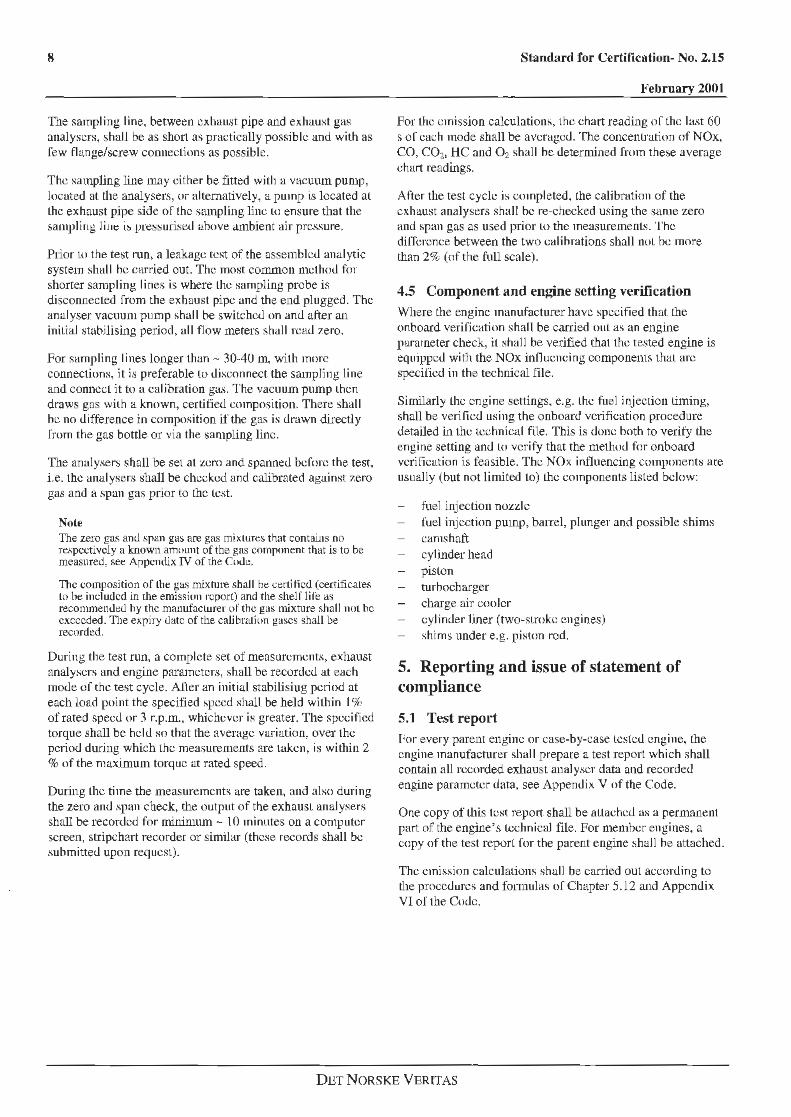
The sampling line, bet.ween exhaust pipe and exhaust gas analysers, shall be as sh011 as practically possible and with as l'ew fl ange/screw connections as possible .
The sampling line m.ay either be fitted with a vacuum pump, located at the analysers, or alternatively, a p ump is located al the exhaust pipe side of' the sampling line lo ensure that the .sampling li11t: i~ pressurisc::d above ambient air pressure.
Pdor Lo the test run, a leakage test of the assembled anal ytic system shall he carried out. T he most common method for shorter sampling lines is where Lhc sampling probe is disconnected from the exhaust pipe and the end plugged. The analyser vacuum pump shall be switched on and after an initial stabilising period, all flow meters shall read zero.
For sampling lines longer than - 30-40 m, with more connections, it is preferable to disconnect the sampling line and connccl it to a calibration gas. The vacuum pump then draws gas with a known, certified composition. There shall be no difference in composition if the gas is drawn directly f'rom the gas bottle or via the sampling line.
The analysers shall be set at zero and spanned before the test, i.e. the analysers 8hall be checked and calibrated against 7.ero gas and a span gas prior to the lest.
Nole The zero gas and span gas are gas mixtures that contains no rc::speeti vcly a known amount of the gas component that is to be measured, see Appendix IV of the Code.
The composition of lhe gas mixrure .shall he certified (certificates lo he included in the emission rcpQrt) and the shelf life a5 recommended hy the manufacturer of the gas mixture shall not be exceeded. The expiry date of the calibration ga~cs shall be recorded.
During the test run, a complete set of measurements, exhaust analysers and engine parameters, shall be recorded at each mode of the test cycle. After an initial stabilising period at each load point the specified speed shall be held within I% of rated speed or 3 r.p.m., whichever is greater. The specified torque shall be held so that the average variation, over the period dming which the measurements are taken, is within 2 % of the maximum torque at rated speed.
During Lhc time the measurements are taken, and also during the zero and s1nm check, the output of the exhaust analysers shall be recorded for minimum - 10 minutes on a computer screen, stripchart recorder or similar (these records shall be submitted upon request).
Standard for Certification- No. 2.15
.February 2001
For the emission calculations, the chart reading or the last 60 s or each inode shall be averaged. The concentration of NOx, CO, C02, HC and~ shall be determined from these average chart readings.
After the test cycli; is completed, the calibration of the exhaust analysers shall he re-checked using the same zero and span gas as used prior lO the measurements. The difference between the two calibrations shall not be more than 2% (of the full scale) .
4.5 Component and engine setting verification Where the engine manufacturer have specified that the onboard verification shall be carried out as an engine parameter check, it shall be verified that the tested engine is equipped wi th the NOx influencing componems thal arc specified in the technical file.
Similarly the engine settings, e.g. lhe fuel injection liming, shall be verified using the onboard verification procedure detailed in the technical file. This is done both to verify the engine setting and lo verify that the method for onboard verification i.s feasible. The NOx intluencing components ace usually (hut not limited to) Lhc components listed below:
fuel injection nozzle fuel injection pump, batrel, plunger and possible shims camshaft cylinder head piston turbocharger charge air cooler
cylinder liner (two-sLrokc engines) shims under e.g. piston rod.
5. Reporting and issue of statement of compliance
5.1 Test report f'<ir every parent engine or case-by-case tested engine, the engine manufacturer shall prepare a tes t report which shall contain all recorded exhaust analyser data and recorded engine parameter data, see Append ix V of the Code.
One copy of U1is test repo1t shall be auachcd as a permanent part of the engine's t.cchnical file. For member engines, a copy of the test report for the parent engine shal 1 be attached.
The emission calculations shall be carried out according to the procedures and formulas or Chapter 5.12 and Appendix VI oJ the Code.
DETNORSKE VERlTAS
Standard for Certification· No. 2.15 9
February 2001
6. Appendix I - specification of exhaust gas analysers
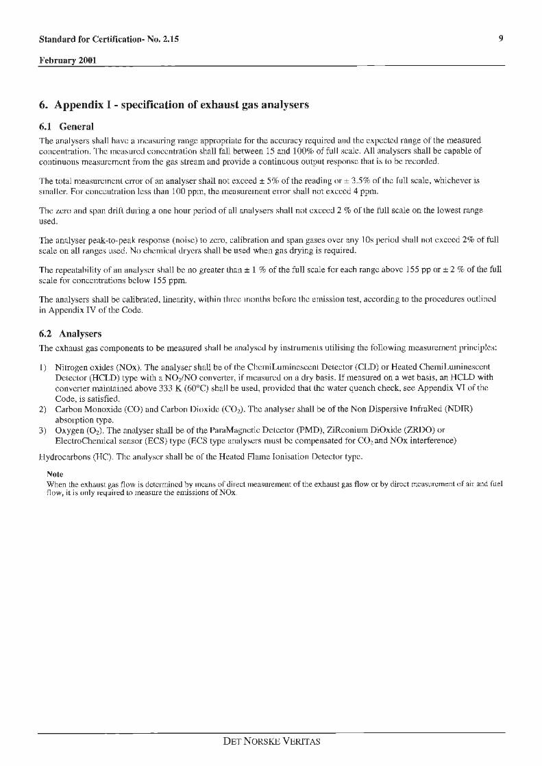
6.1 General The analysers shall have a measuring range appropriate for the accuracy required and the expected range of the measured concentration. The measured concentralion shall fall between 15 and 100% of full scale. All analysers shall be capable of continuous measurement from the gas stream and provide a continuous output response that is to be recorded.
The total memmrcmcnl error of an analyser shall not exceed ± 5% of the reading or± 3.5% of the full scale, whichever is smaller. For concentration less lhan 100 ppm, the measurement error shall not exceed 4 ppm.
The zero and span drifl duiing a one hour period of all analysers shall not exceed 2 % of the full scale on the lowest range used.
The analyser peak-to-peak response (noise) to zero, calibration and span gases over any I Os period shall not exceed 2% of full scale on all ranges used. No chemical dryers shall be used when gas drying is required.
The repeatability of an analyser shall be no greater than± 1 % of the full scale for each range above 155 pp or± 2 % of the full scale for concentrations below 155 ppm.
The analysers shall be calibrated, linearity, within three months before the emission test, according to the procedures outlined in Appendix IV of the Code.
6.2 Analysers The exhaust gas components to be measured shall he analysed hy instrumenls utilising the following measmement principle.-;:
I) Nitrogen oxides (NOx). The analyser shall be of the ChcmiLuminescenl Delector (CLD) or Heated Chemil ,uminescent Detector (HCLD) type with a N02/NO converter, if measured on a dry basis. If measured on a wet basis. an HCLD with converter mainlained above 333 K (60°C) shall be used, provided that lhe water quench check, see Appendix VT of the Code, is satisfied.
2) Carbon Monoxide (CO) and Carbon Dioxide (C02). The analyser shall be of the Non Dispersive lnfraHed (NDJR) absorption type.
3) Oxygen (02). The analyser shall be of the ParaMagnctic Detector (PMD), ZiRconium DiOxide (ZRDO) or ElectroChemical sensor (ECS) type (ECS type analysers must be compensated for C02 and NOx intelference)
Hydrocarbons (HC). The analyser shall be of the Heated Flame Ionisation Detector type.
Note When the exhaust gas flow is determined by mean:; of direct measuremelll of the exhaust gas flow or by direct measLtrcment of air and fuel flow, it is only required lo measure the emissions of NOx.
DET N ORS KE VERITAS
IO Standard for Certification- No. 2.15
l<'ebruary 2001
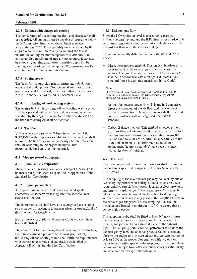
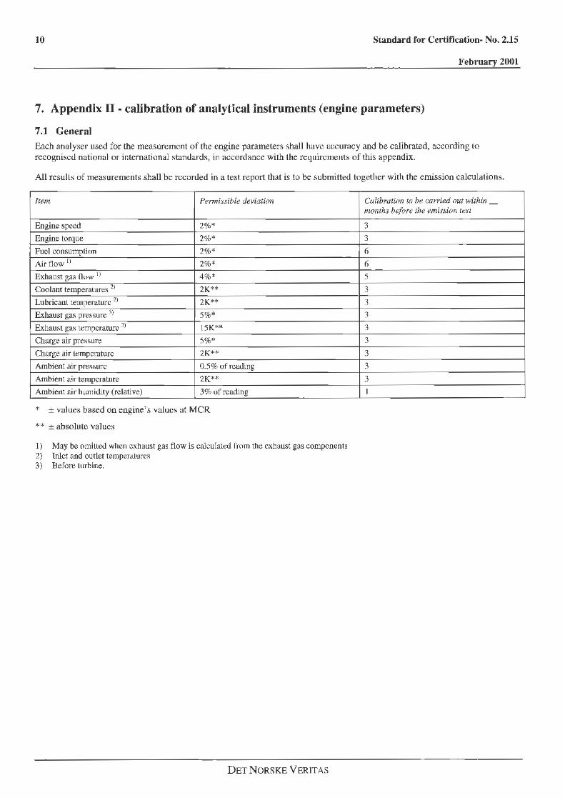
7. Appendix II - calibration of analytical instruments (engine parameters)
7.1 General Each analyser used for the measurement of the engine paramelers shall have accuracy and be calibrated, according lo recognised national or intemalfonal stamlards, in accordance with the requirnments of this appe.ndix.
AU results of measurements shall be recorded in a test report that is to be submitted together with the emission calculations.
Item Pe.nnissible deviation
Engine speed 2%*
Engine torque 2%*
Fuel consumption 2%*
Air flow ll 2%*
Exhaust ga.s now I} 4%*
Coolant temperatures 2J 2K**
Lubricant temper.uure 21 2K**
Exhaust gas pres.~ure 3l 5%~'
Exhaust gas temperature 3l 15K"*
Charge air pressure 5%*
Charge air temperature 2K*"
Ambient air pressure 0.5% of reading
Ambient t1ir temperature 2K**
Ambient air humidity (relative) 3% of reading
* ± values based on engine's values at MCR
** ±absolute values
I) May be omitted when exhaust gas flow is calculated Crom the exhaust gas components 2) lnlct and outlet tempernlure~ 3) Before turhine.
DET NORSKE VERITAS
Calibration to be carried out within _ months b~f'ore the emission test
3
3
6
6
5
3
3
3
3
3
3
3
3
I


II
I
I
I
'
' I
I
I
DET NORSKE VERITAS Det Notske Veritas is an
autonomous, independent Foundatiom with the objective of safeguarding life, property
and the envirenment. The DNV organisation comprises
300 offices in 100 countries, with a total of 4,400 employees.