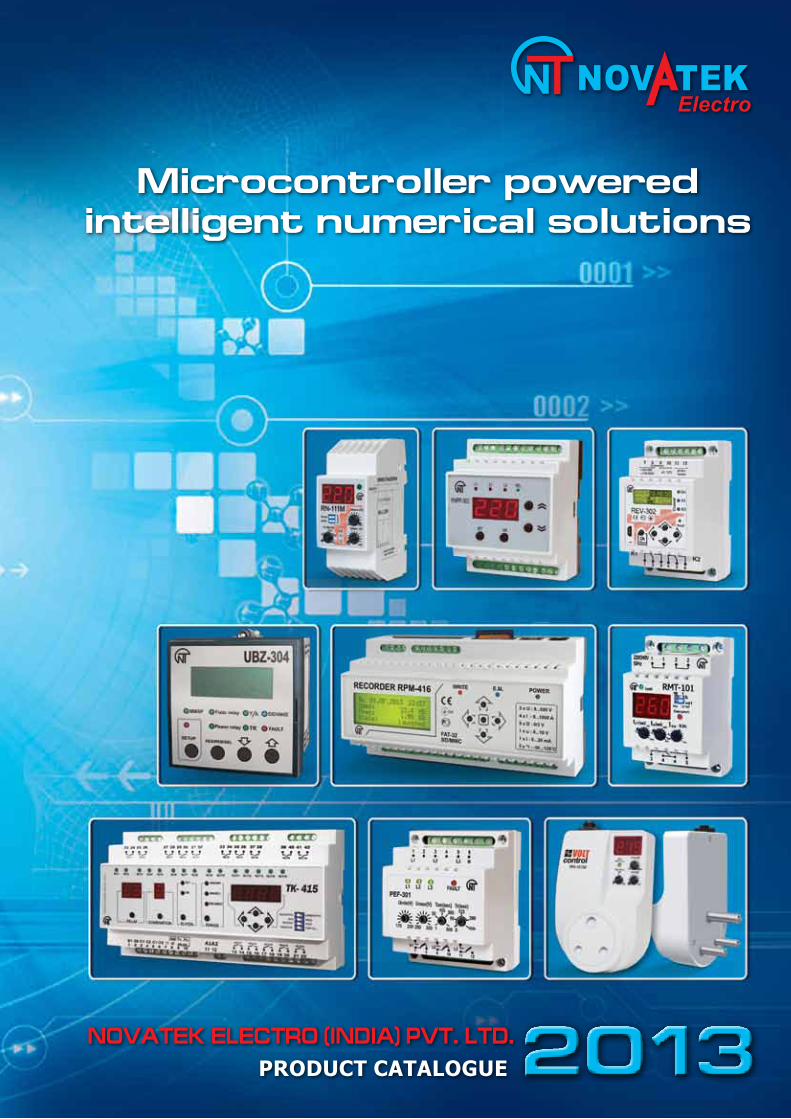
novatek electro (india) pvt. ltd., delhi, microcontroller based devices
TRANSCRIPT
Electro
PRODUCT CATALOGUE 2013NOVATEK ELECTRO (INDIA) PVT. LTD.
Microcontroller powered intelligent numerical solutions
Dear All, Wewouldliketothankyouforyourpatronageandinterestinoursphereofactivityandproducts.Thiscataloguecontainsinformationonnewdevelopmentsaswellasproductsthatyouarealreadyacquaintedwith. IthasbeenourconstantendeavortoemployhighestgradeprofessionalsinthefieldofResearch,DesignandManufactureofinnovativemicrocontrollerbasedprotection,automationandcontroldevices.Ourcustomersarepeoplewhoprefersafetyinelectricaloperation,highlyefficientandreliableprotectionandcontrolsfortheirmachineryandequipment. Novatek-ElectroLtd.wasestablishedinoneofthemajorUkrainianportcity-Odessain1991.Companyconsistsofhighlyexperiencedspecialistsinthefieldofembeddedtechnologyaswellasengineersofcontrolandsafeoperationofalltypesofelectriccircuitsandpowersystems. InadditionNovatek-ElectroLtd.hasnumberofresearchworkers,scientistswithPh.D.degree,researchengineersandspecialistsinpowerelectronics,lasertechnology,etc.Thisallowsus to designandmanufacture newgenerationproductswith outstanding reliability and functionality. Someof theproductsbyNovatek-ElectroLtd.havenoanaloguesandcouldbeconsideredatthelevelofscientificdiscoveries. ProductsandserviceswhichourCompanyprovidesthroughtheyearsgotverygoodrecognitionandarewidelyacknowledgedinUkraine,RussiaandotherCIScountries,EuropeanUnion.AtpresentactivesaleshasstartedinIndia,Pakistan,Kenya,Nigeria,Ghana,Vietnam,Argentina,Brazil,CostaRica,MiddleEast,etc. Our customers and clients represent wide range of industries with varied areas of applications for theinnovativesolutionsandproductsthatourcompanyprovides.Theseincludesteelandmetallurgicalindustries,miningcompanies,oilandgascompanies,powergenerationanddistributioncompanies,transportsystems,refrigerationandair-conditioningcompanies,telecommunicationandelectricpanelmanufacturersandpartiallyprivateandconsumersector.Inanut-shellwearehonoredtomentioncompanieslikeARCELLOR-MITTAL,ZAPOROZHSTAHL,SEVERSTAL(SteelPlants);MARIUPOLMETALLUGRICALPLANT;SEVGOKMINES;Majoroilcompanies likeLUKOIL,GAZPROM,FERGANAandASTUKREFINERYPLANTS;intelecommunicationssector–MTS,BEELINE,MEGAPHONE,TELEVISA,IPKOandothersasourvaluedcustomers. NovatekElectro(India)Pvt.Ltd.isalreadyregisteredwithmajorIndianPSUsandProjectConsultantsviz,NTPC,ONGC,UttarPradeshRajkiyaNirmanNigam,MotherDairy,NALCO,IFFCO,Potential-SemacConsultants(P)Ltd.,M.N.Dastur&Co.(P)Ltd.,DevelopmentConsultants(P)Ltd.,RSPDesignConsultants,etc. ProductsbyNovatek-ElectroLtd.areextremelyreliableandeffectivelyworkinalltypeofclimaticconditionsfromverylowtemperatureofdeepRussianNorthtohotandhumidclimateofIndiaandAfricancountries.
Principles which we dedicatedly follow are – reliability, multi-functionality, high quality and reasonable/affordableprice.Highreliabilityandqualityisattainedwiththeuseofmostmoderntechniquesandtechnologiesonthebaseofmicroprocessorsandmicrocontrollers.Theassemblyofproductsisbeingperformedonthenewestandmodernequipmentofknownandreputedbrands.Experiencedengineersandprogrammersareusingmostmodernsoftwaretoolsandprogramssetstocreateeasytoinstall,maintenancefreeSCADAcompatibledevices. Ourlongtermaimistorevolutionaliseautomationandcontrolindustrywithreadytouseaffordableequipments,whichcanbeusednotonlybytheGiantsofIndustrybutwouldalsofitthepocketsofSmall&Mediumscalesector.
YoursSincerely,Novatekmanagementteam
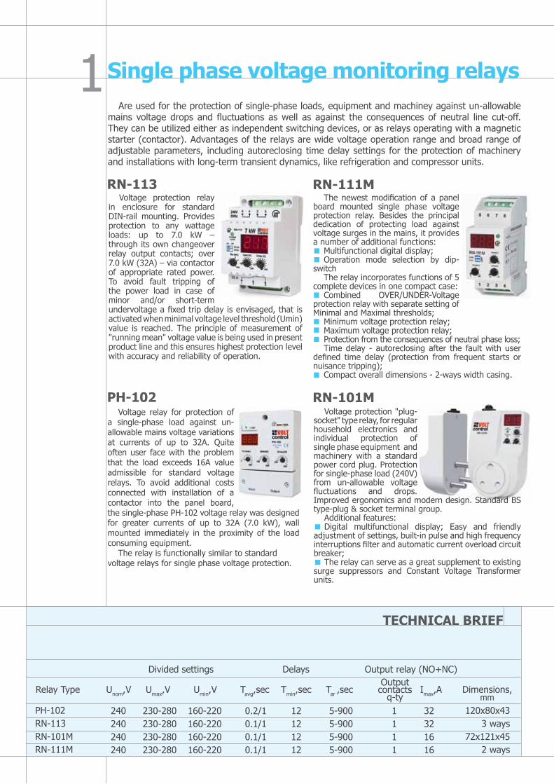
The newest modification of a panel board mounted single phase voltage protection relay. Besides the principal dedication of protecting load against voltage surges in the mains, it provides a number of additional functions:
Multifunctional digital display;Operation mode selection by dip-
switchThe relay incorporates functions of 5
complete devices in one compact case:Combined OVER/UNDER-Voltage
protection relay with separate setting of Minimal and Maximal thresholds;
Minimum voltage protection relay;Maximum voltage protection relay;Protection from the consequences of neutral phase loss;Time delay - autoreclosing after the fault with user
defined time delay (protection from frequent starts or nuisance tripping);
Compact overall dimensions - 2-ways width casing.
Voltage relay for protection of a single-phase load against un-allowable mains voltage variations at currents of up to 32A. Quite often user face with the problem that the load exceeds 16A value admissible for standard voltage relays. To avoid additional costs connected with installation of a contactor into the panel board, the single-phase PH-102 voltage relay was designed for greater currents of up to 32A (7.0 kW), wall mounted immediately in the proximity of the load consuming equipment.
The relay is functionally similar to standard voltage relays for single phase voltage protection.
Single phase voltage monitoring relaysAre used for the protection of single-phase loads, equipment and machiney against un-allowable
mains voltage drops and fluctuations as well as against the consequences of neutral line cut-off. They can be utilized either as independent switching devices, or as relays operating with a magnetic starter (contactor). Advantages of the relays are wide voltage operation range and broad range of adjustable parameters, including autoreclosing time delay settings for the protection of machinery and installations with long-term transient dynamics, like refrigeration and compressor units.
RN-113Voltage protection relay
in enclosure for standard DIN-rail mounting. Provides protection to any wattage loads: up to 7.0 kW – through its own changeover relay output contacts; over 7.0 kW (32A) – via contactor of appropriate rated power. To avoid fault tripping of the power load in case of minor and/or short-term undervoltage a fixed trip delay is envisaged, that is activated when minimal voltage level threshold (Umin) value is reached. The principle of measurement of "running mean" voltage value is being used in present product line and this ensures highest protection level with accuracy and reliability of operation.
RN-111M
Voltage protection "plug-socket" type relay, for regular household electronics and individual protection of single phase equipment and machinery with a standard power cord plug. Protection for single-phase load (240V) from un-allowable voltage fluctuations and drops. Improved ergonomics and modern design. Standard BS type-plug & socket terminal group.
Additional features:Digital multifunctional display; Easy and friendly
adjustment of settings, built-in pulse and high frequency interruptions filter and automatic current overload circuit breaker;
The relay can serve as a great supplement to existing surge suppressors and Constant Voltage Transformer units.
RN-101M
PH-102RN-113RN-101MRN-111M
240240240240
230-280230-280230-280230-280
160-220160-220160-220160-220
0.2/10.1/10.1/10.1/1
12121212
5-9005-9005-9005-900
1111
32321616
Relay Type Unom,V Umax,V Umin,V Tavg,sec Tmin,sec Tar ,sec Imax,A Dimensions,
Divided settings Delays Output relay (NO+NC)
TECHNICAL BRIEF
120x80x433 ways
72x121x452 ways
Output contacts
q-ty mm

The relay is a multifunctional programmable controller providing protection in AC 240/415 or 220/380 Volt,50Hz circuits. The relay repeats all RNPP-301 functions including the magnetic starter/contactor full phase terminals monitoring. In each operation mode the user selects the set of parameters to be monitored on the front panel. Besides, the relay is equipped with a digital input that locks the relay in case of a fault. An additional feature: Three-phase digital voltmeter that displays actual phase/line voltage RMS value.
Multifunctional Three phase voltage monitoring relays
Are used for protection of three phase loads against un-allowable mains voltage variations, phase loss, phase imbalance, phase coincidence and incorrect phase sequence. They are highly effective for the protection of any three phase electrical equipment and circuits, including equipment with long-term transient dynamics and electric motor load as well as installations where continuous monitoring of quality, availability and three phase lines presence of the mains voltage is required, for example in automatic load transfer panels (ATS-panels).
RNPP-301
RNPP-302
The relay is designed for protection of machinery and circuits which are most critical to all of the power supply parameters. It has 6 independent adjustable settings for the basic parameters. The benefit of RNPP-301 is a capability of operation within two types of circuits with isolated (3 wire) and solidly-earthed neutral (4 wire) electrical circuits. The relay provides accurate true RMS voltage monitoring and control over the full phase switching of a magnetic starter/contactor terminal contacts. Separate front panel LED indication pattern for each type of fault. Use of a complex information processing algorithm allows to make different decisions depending the type of a fault and either allow autoreclosing when the power parameters get back to normal or block further operation until the service engineer to come for the problem solution if the fault could not be solved by itself.
RNPP-311 is a simplifiedversion of RNPP-301 stated above and designed for majority of users. It has one combined setting knob for Maximal and Minimal voltage level thresholds and thepossibil-ity to set up different time ranges for autoreclosing. This protection relay provides tripping basing the RMS voltage value for the period and combined indication for all detected faults. RNPP-311 has 2basic modifications: frequency control and specialаlgorithm of output contacts operation. Highlyefficient for the protection of refrigeration, compressor, ventillation machinery. This RNPP-311 is a necessary component of different types of ATS switches and power supply control panel boards.
The relay is designed for protection of all the faults that may happen for the majority of customers. It is budgetary version of RNPP-301 and has one combined adjustment for voltage level thresholds, and possibility to modify the tripping time delay and autoreclosing time delay. Front panel DIP-switches allow to select the type of the monitored circuit (400 or 415V), and to arrange and combine different operation modes. Such simplification allowed to decrease the cost of the product significantly and keep all most frequently required protection modes. The product finds broad application in protection of refrigerating units & compressor, ventilation equipments, etc. The relay is necessary element of any automatic load transfer panels as well as power supply control panels. Optionally there is a possibility of 24V DC power supply for continuous monitoring in case of power loss (optional function for client's special order).
THE LEvEL OF PROTECTION AND NUMBER OF FUNCTIONS FOR RNPP-311M IS UNRIvALED!
RNPP-311M
RNPP-311
TECHNICAL BRIEF
Proportional Divided Delays
Settings Output relay (NO+NC)
Relay Type Unom,V Umax/Umin Umax,%UH Umin,%UH Imbalance Tavg,sec Tmin,sec Tar ,sec Imax,A Dimensions,
RNPP-301RNPP-302RNPP-311RNPP-311M
240-415
220-380/240-415
240-415
230-400/240-415
5-20%
5-35%
60 V
60 V
5-25%Unom
5-50%Unom
4 ways
4 ways
3 ways
2 ways
Output contacts
q-ty
5-25
0-30
5-25
0-60
0-10
0.1-30
1.5(0.1)
0-10
0-20
0.1-30
12
12
0-600
0.5-600
5(0-250)
0-600
2
2
2
2
5
8
3
5
mm
REV-201 timing relays are designed for providing precise and accurate timing in different automatic control and regulation panels and circuits; they can also serve as a key element in controlling complex technological schemes and processes. The relay is designed in different versions with adjustable power-on delays from 0 sec to 36000 sec (10 hours). IT is capable of switching AC circuits of ~240V/50Hz voltage, and DC circuits of 24-100V.
The relay can operate in four modes: Independent channel operation (two relay mode); Parallel channel operation (one relay with two independent delays mode); Serial (summing) channel operation;Switch-back “trigger” (crossed) channel energization schematic (cyclic relay mode). Relays versions are
available with a circuit control relay function that energize channels according to a preset program. The relays can also find application in star-delta electromotor start switching circuits, in cascade connections. One of the relay versions (REV-201-5) is used for pre-start alarm system implementation according to the regulations of the Federal Committee for Industrial and Mining Safety Supervision.
The REV-201M two-channel timing relay combines features of all currently produced REV-201 relays. It provides the following operation modes for each channel:
Time delay relay;Pulse relay;Periodic (cyclic) relay;Switching control relay (including prestart alarm systems).The relay can be powered either by 220-240V AC voltage, or by operational supply
of 24V DC. The package dimensions have been reduced to standard 2 ways width. The relay features high accuracy of the setting stability (error max 1%). Double color LED indicates the status of the output channels. Another feature is low power consumption under load, ≤ 1W. Using DIP-switches on the front panel allows to achieve minimum 4 operation algorithms and a wide range of time settings: from 0 to 36000 sec. Design of the relay allows smooth setting adjustment. At each channel’s output a group of switchover terminals (one NC, one NO) of 7A capacity is installed.
Multifunctional time delay relays
REv-201 Two channel time delay relay
REv-201M Multifunctional two channel time relay
TECHNICAL BRIEF
REV-201REV-201-1REV-201-2REV-201-3REV-201-5REV-201M
0-220 sec0-23 min
0-10 min; 0-10 sec2.5 min – 10hrs10-30-10 sec
Program
~220-240~220-240~220-240~220-240~220-240
~220-240/=24 AC/DC
222222
333337
3 ways3 ways3 ways3 ways3 ways2 ways
Delays Output Relay (NO+NC)
Relay Type Unom,V Tavg,sec Q-ty Imax,A Dimensions

Two channel multifunctional programmable astro timer with
photo sensor and voltage protection
Multifunctional timer REV-302 is a microprocessor based programmable device designed to energize/de-energize one or two independent loads with user preset time intervals and preprogrammed schedule of events. It may also take into account the level of illumination and voltage level in the power supply circuits to operate with any time, light or voltage dependent processes and equipment. REV-302 timer has universal input power supply of DС = 100-300V, AC ~ 90-420V and alternatively could be powered by reserve supply source of DС = 8-30V. You can program this device as a daily, weekly, monthly and yearly timer with possibility of a specific list of exceptional events for days off and holidays.
REv-302 multifunctional programmable yearly timer with external photo sensor, voltage protection & astro functions
REV-302 ~220-240 94-420 90-416 1-1200 2 16 3 ways
Relay Type Unom,V Umax,V Umin,V Tar ,sec Q-ty Imax,A Dimensions
Divided settings Delays Output relay (NO+NC)
TECHNICAL BRIEF
REV-302 has a possibility to create and save program of the events in the PC and then load them into the timer using a USB connection cable. Also through the PC connection you can input your exact geographical location – Latitude and Longitude and timer will automatically set the schedule of sunsets and sunrise at your exact installation point. There is a possibility of combination of different functions of timer, photo sensor and voltage monitoring relay to operate simultaneouly with your power load as per requirement. Itself is a complete solution for automatic street light switching.
8 independent control programs (up to 5000 events can be pre-programmed) and possibility of swift transfer between them. Automatic summer and winter time conversion. RTC with 10 year calendar and internal power supply (Li-Ion battery) to keep the program in case of power off or long disuse. Periodic timing relay function (periodic calendar independent contacts close/open) with auto reset delay.
L1
N~ 90-420V AC=100-300V DC
photo-sensor
7 8 9 10 11 12 power
1 2 3 4 5 6
Load No1 Load No2
On
K1
K2Cha
nnel
Reset
OkMenuUSB
REV-302
K1 K2
=8-30V DC
RN-16TM weekly timer with voltage protection function and case-integrated photo relay
Basic function and application of this product are as follows:
Energizing/de-energizing industrial and household single phase loads in
accordance with the user-required time schedule within a week time range;
De-energizing load in case of inadmissible voltage variations in the mains
with subsequent automatic re-energizing after the mains parameters recover
(integrated voltage sensitive relay);
Load de-energizing according to reaching certain illumination levels
(integrated photo relay).
Relay Type Unom,V Umax,V Umin,V Tavg,sec Tar ,sec Imax,A Dimensions
Divided settings Delays Output relay (NO+NC)
TECHNICAL BRIEF
RN-16TM ~220-240 230-320 150-210 0-9.9 0-9.9 1 16 3 ways
Programmable timer with photo relay and voltage protection
Maximum number of programmable
events in the timer mode – up to 420.
The timer may operate with power loads
up to 16 A directly through its output
relay contacts, and over 16A – via
magnetic contactor. The timer operates
with two independent programmable
command sets, within five operation
modes and four timing modes. It is
equipped with a non-volatile memory
which allows saving programmed
parameters in case of power loss.
Can be effectively used for heating
and water supply systems, climate
and lighting control, in agricultural
equipment as well as "smart home"
systems.
L
N
220V50Hz
1 1 2 2
3 4 4 5
ON F H U
POWER
16A
PROTECTEDPOWER LOAD
UP TO 16A
RN-16TM
Output contacts q-ty

Sequential and Combination timer for process control
TK-415 15 channel sequential cum combination timer
Specific features:
Microcontroller based Sequential cum Combination
timer (selectable operation mode);
Simple change over between sequential and
combination mode;
LED display for selection/ programming and LED
indication for channel in operation;
Cascade connection of several devices for extension
of total number of channels;
Memorization of device mode and program after switching off and program operation restart from breakage;
Inputs for timer start and pause control;
Fast resetting;
Copy of settings;
Program can be executed only one time and/or cyclic operation possible.
RS-232 communication for programming through computer via free software provided with device;
Three selectable time range (1min-99.59hrs, 1sec-99.59min, 100ms-999.9sec)
S. No Features TK-4151 Supply voltage 85 to 270 V AC/DC
2 Frequency range 47-63 Hz
3 Power consumption 8 W
4 Time setting range 100ms to 99hr59min
5 Commutation accuracy ±0.1% + 20ms
6 Number of channels 15
7 Number of combinations per channel (ON/OFF) 8
8 Insulation resistance >100МOhm @ 500V DC
9 Indication of load relay (potential free) Yes
10 Protection level ІР20
11 Climatic resistance version УХЛ4
12 Data memory, years, minimum 10
13 Operating temperature range -35 to +55 °С
14 Dimensions, mm 85.8 х 156.2 х 56.8
15 Mounting onto standard 35 mm DIN-rail
16 Mounting position - any
сos j Maximum current at U~250v Maximum capacity Maximum current at
Uconst=24v
1.0 10 A 2500 VA 10 A
0.4 4 A 1000 VA
Commutation resource of output contacts: - mechanical resource - electric resource 10A 250V AC, times, minimum - electric resource 10A 24V DC, times, minimum - electric resource 4A 250V AC (сos j = 0,4 ), times, minimum
107 100 00030 000100 000
Characteristics of output channels

KRM-136 Three phase 6 stage power factor correction relay
KRM-136, Three Phase 6 Stage Reactive Power Controller (“KRM”) is
used to measure the parameters of a three phase circuit and control the
reactive power compensation capacitor banks.
Technical capabilities of KRM-136:
parameters display: power factor, type of load (inductive/capacitive);
linear voltage, phase current, frequency; active, reactive and full power;
temperature;
precise power factor measuring algorithm, including cases of sinusoid
distortions (odd harmonics 1 to 19);
controlling the capacitor banks air temperature using temperature sensor, with option for forced cooling or
heating;
minimum rigid correlation between regulation stages;
counting the number of power on/off instances of each stage to determine the wear of the stage’s elements;
even distribution of commutations between stages of equal power;
quick capacitor switch-off;
RS-485 MODBUS interface for communication and SCADA integration.
Numeric power factor controller
S.No Features KRM-136
1 Linear voltage measuring range 90 – 450 V
2 Nominal current of 5A measuring input Range of measured line currents depends on the current transformer used 0.025 – 5 А
3 Power factor regulation 0.7 ind. – 0.7 cap.
4 Active voltage of switched circuits 220 V
5 Number of capacitor stages controlled 6
6 Data Communication interface RS-485
7 Communication protocol MODBUS
8
Inputs- analog input for current transformer with 5 A output;
- analog input for NTC temperature sensor;
- emergency switch-off input for external forced switch-off of stages
Yes
Yes
Yes
9
Outputs- 6 outputs for capacitor bank contactor controller relay, one shared output
- cooling/heating relay – one group of transfer contacts for controlling the
capacitor bank rack cooling/heating system
- emergency relay – one group of transfer contacts for emergency signaling
Yes
Yes
Yes
10 Operation temperature range -25 to +55 °С
11 Dimensions 96 x 96 x 89 mm
Motor winding insulation resistance level
test before start (if the insulation resistance
is at level of 0.5 М Ohm the start is disabled);
Ground/Earth fault protection during
operation then automatic restart is
prohibited;
Simple and accurate setting of motor
parameters like rated current parameters
before start considering long term overload.
Overload tripping with a dependent time
delay by solving motor thermal balance
differential equation (I2t).
Highly visible and logical LED front panel
indication. Possibility to incorporate motor
protection unit to SCADA systems with the –
Data exchange unit BO-01 according to RS-
485 MODBUS protocol (BO-01 is supplied
on request at additional cost).
Induction motor protection deviceLatest trend and new line of products in the field of accurate and precise protection of the
induction electric motors and pumpsComplete protection against all possible types of faults, including circuit faults and mechanical
motor defects detectionVector analysis of currents; Calculation of Motor's Thermal balance through heating balance
differential equation based on the analysis of currents consumed by AC motor Protection and control of electric motors and pumps from 2.5 kW to 315 kW rated power
UBZ-301 asynchronous induction motor protection device
Is designed for continuous monitoring of mains voltage parameters and
RMS phase/line currents of 3-Phase AC 415V/50Hz electrical equipment,
primarily of induction motors and pumps, including those functioning
within insulated neutral circuits. Produced in three separate modifications
of 5-50А, 10-100А, 63-630А.
The unit provides full and effective protection of electrical equipment
by isolating from the running system and/or disabling its start. This is
performed in the following cases:
When the mains voltage is of poor quality (un-allowable voltage surges,
phase loss and phase/line voltage imbalance, incorrect phase sequence
and short circuit condition);
Mechanical overloads (symmetrical phase/line current overload); phase/line current asymmetrical
overloads induced by faults inside the motor; phase current asymmetry without overload, that is induced by
the insulation fault inside the motor and/or the power cable (earth leakage);
Based on the minimum start and/or operating current parameter - when motor momentum is lost or lost
load condition ("dry run" in case of pumps);
L1L2L3N
voltage monitoring
~240VSTARTER
DIFFERENTIAL CURRENT
PROTECTION
CURRENT MONITORING
AC MOTOR
Computeror
DCS
RS-485
RS-232via COM-PORT
Windings Insulation Check
Exchangeunit
Cb
K

An extended set of integrated protections combining following functions: overload relay, phase monitor relay, over current relay (over current protection with independent and time-dependent delay), leakage current monitor, motor heat protection relay (thermal overload);
Monitoring all power parameters and volt-ampere reactive;Protection against long lasting start and rotor jamming;Possibility of manual control with use of the device front panel;Fault history log;Free software: Interface panel and SCADA (Novatek Device Manager wizard);
Induction motor protection device (numeric motor protection relay)Operation of UBZ-302 connected to PC or SCADA system allows to control and analyze number of additional parameters:
Data exchange and SCADA integration
UBZ-302 universal electric motor protection deviceDesigned for continuous monitoring of three phase electrical
equipment parameters (primarily 3-phase asynchronous induction electric motors): mains phase/line voltage, phase/line RMS currents, wattage, positive and negative sequence voltages and currents, insulation resistance to frame, differential ground leakage currents (zero sequence currents), temperature operation modes. The unit has been designed for wide range of applications in the buildings engineering systems (heating, ventilation, water supply, air-conditioning and lifts), Automatic Process Control Systems and Industrial Automation Systems, Control Accounting and Scheduling Systems. The unit allows to reduce the probability of 3-phase electrical equipment failure, reduce the operation cost, optimize the energy consumption and enhance the operational convenience. It is equipped with complete set of protections implemented in UBZ-301. It additionally provides protection against long lasting start and rotor jamming. Besides, the device monitors the motor winding overheating by means of external temperature sensors. Availability of the second output relay allows arranging the following additional operation modes:
Star-delta switching;«Delayed start» power-on (for example, cascade motor starting);Remote signaling system relay
The integrated modem allows for data exchange with relatively positive state systems via RS-232 or RS-485 MOSBUS RTU protocol (selectable).

L1L2L3N
RS-485 INTERFACE TEMPERATURE GND A RS-485 Sensor 1 b RS-485 t R1 100 STANDARD INPUTS Sensor 2 Voltage Current t R1 100
GN
DA
N_U
GN
DA
N_I
MMSP EXCHANGE RS-232 FAULTFunctional relau Power relay UBZ-302 SETUP RES|MEM|SEL TR
TxD_rs232RxD_rs232GND_rs232
27 28 29 30 31 32 33 34 35 39 40 44 45 48 49 50 51 52
R2 R1-1 R1-2
1 2 3 4 5 6 7 8 9 14 15 16 17 18 19 23 24 25 26
CIRCUITbREAKER
M3~
MOTOR ACT1
T2
T3
T4 CONTACTOR
S.No Features UBZ-302
1 Rated Voltage SupplyPhase voltage
400V – 450V180V – 240V
2 Frequency Operations 45-63Hz
3 Power Supply Self Powered
4
Required accessoriesPT CT < 63A > 63ACB CT (Earth Leakage)
Not Required (built in)Not required (built in)RequiredProvided
5Output Relay (Potential free) 2 (3 NO+NC)
1-Power Relay2-Functional Relay
6 Communication Port- RS-232 RS-485 Modbus RTU
YesYes
7 Operating Temperature -35 to +55°С
8 Measuring Value RMS
9
voltage Protection with Delay Timer1-Under voltage3-Over voltage4-Line Voltage Imbalance5-Wrong Phase Sequence6-Short Circuit7-Phase Loss/ Phase failure8-Single Phasing
YesYesYesYesYesYesYes
10
Current Protection with Delay Timer1-Maximal Current protection 2-Earth Leakage3-Reverse current sequence4-Inverse sequence current5-Minimal current protection6- Current Overload7-Excessive long start
YesYesYesYesYesYesYes
11 Thermal Overload Protection Yes
12Over Heating Protection (2 RTD sensor inputs for bearing cage, gearbox, etc.)
Yes
13 Analog transducer input (4 - 20mA) Yes
14 Analog transducer input (0 - 10V) Yes
15 Rotor Jamming/Locked Protection Yes
16 Loss of Load (Dry Run) Protection Yes
17 Motor Coil Insulation level Protection Yes
18 Auto Reclosing/ restarting motor with or without delay
Yes
19 Star Delta Motor Starter fuction Yes
20 Remote tripping of Motor (RS-485) Yes
21
Measurement/ MonitorReal Time Monitoring SoftwareThermal Overload graphMotor Current Phase & Residual CurrentPhase VoltageLine voltageNegative Sequence Voltage/CurrentZero Sequence Voltage/CurrentFrequencyPower (active, reactive, cos j)Insulation Resistance of MotorExternal Temperature Measurement
YesYesYesYesYesYesYesYesYesYesYesYes
22 Recording & Analysis of Parameters Yes
23 Trip Cicuit Supervision Yes
24 Fault History Log (Last 5 Faults) Yes
25 Cascade Motor Starting Yes
26 Weight 0.56Kg
27 Humidity < 95% non- condensing
28 Replacement Guarantee 3 Year
Numeric AC Motor Protection Device – UBZ-302
UBZ-304 Numerical motor protection relay with communication for SCADA integration
Induction motor protection device
UBZ-304 universal induction electric motor protection unit (“UBZ”) is used for
protection of asynchronous electric motors (2.5 to 315 kW) that use external
standard current transformers with output current 1 A or 5 A (selectable).
UBZ can work in circuits both with neutral or isolated neutral.
Configuration type – 96 x 96 Flush mounting with backlit LCD display and LED.
UBZ provides for constant control of the circuit voltage parameters, effective
values of phase/linear currents of 415V 50 Hz three-phrase electric equipment,
and checks the insulation resistance of electric motors.
UBZ provides for electric motor protection in case of:
Low quality circuit voltage & frequency [extreme voltage surges, phase failures (single phasing), incorrect
phase sequence and imbalance (asymmetry) of phase/line voltage, frequency outside of the given range];
Mechanical overload (symmetric overload of phase/line currents);
Exceeded threshold of negative sequence current (phase current asymmetry/imbalance);
Asymmetry of phase currents without overload, related to disrupted insulation inside the motor and/or the
lead cable (comparing the negative sequence current asymmetry coefficient to the negative sequence voltage
asymmetry coefficient);
Lost torque on the electric motor drive shaft (“dry run” for pumps) – minimum start and/or working current
protection;
Delayed motor start or rotor blocking;
Low insulation level between the motor stator and housing (checking is done before switching on);
Earth fault of the stator winding during operation – earth leakage current protection;
Thermal overload of the motor;
Winding overheating (measuring the temperature of windings using internal sensors/thermisters or the
housing temperature using external RTD type sensors).
For each type of protection, automatic re-closing can be allowed or forbidden.
The unit protects electric equipment by controlling the magnetic starter (contactor) coil.
The unit determines the presence of the motor currents when the load relay is switched off (switched off load
relay and functional relay in star-delta mode). In this case, the unit induces emergency on the external motor-
activating contactor/breaker until the unit is switched off.
The unit provides for:
Control and transfer of parameters via RS-485 interface by the MODBUS protocol;
Control and transfer of parameters via RS-232 interface.
Note – simultaneous use of the RS-485 and RS-232 interfaces is not possible.
Real time monitoring, logging and controlling of UBZ parameters is possible with the UBZ-304 Control Panel
software, available free of cost in the website of Novatek-Electro Ltd.
UBZ-304 Control Panel software is used to control the status and collect data from UBZ-304 units, using
RS-232 or RS-485 interfaces. The software allows
saving (programming) various UBZ settings,
collecting data and saving them for further
study/analysis. The saved data can be viewed in
graphical format for parameter comparison.
The GUI of the control panel allows observing
the current status of various UBZ parameters in
real time. The flexible settings allow customizing
the interface for the requirements of any user.
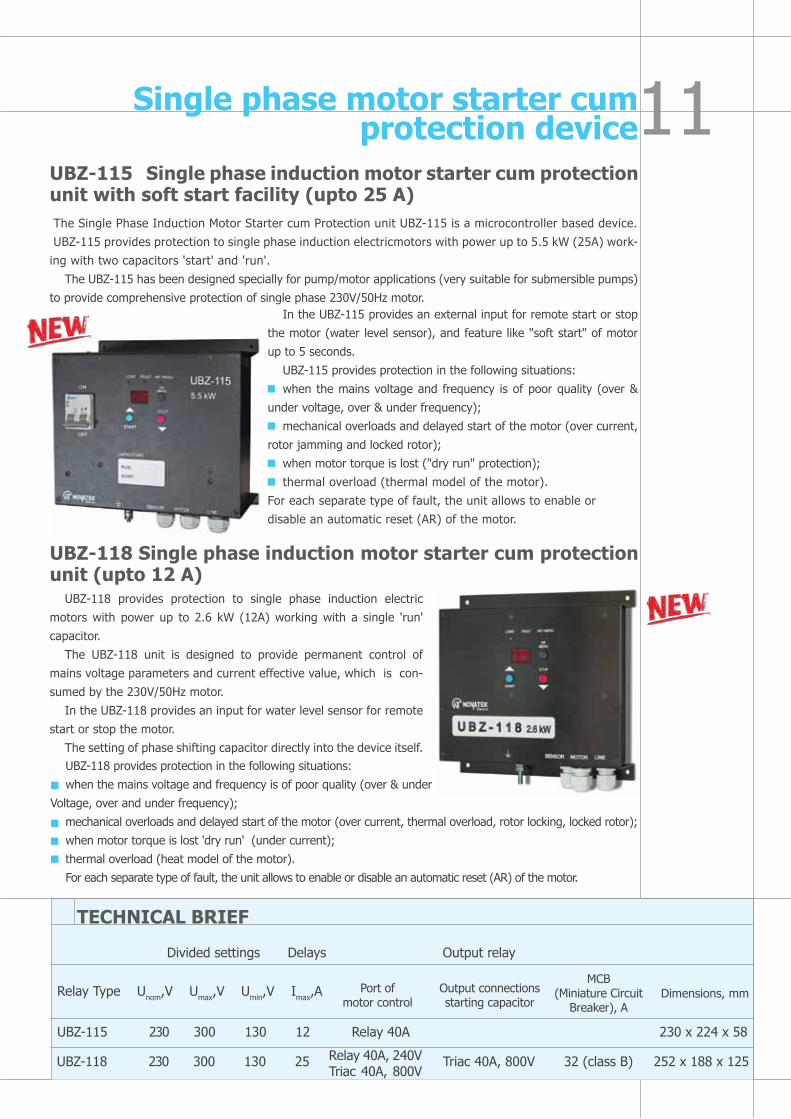
UBZ-115 Single phase induction motor starter cum protection unit with soft start facility (upto 25 A)
Single phase motor starter cum protection device
In the UBZ-115 provides an external input for remote start or stop
the motor (water level sensor), and feature like "soft start" of motor
up to 5 seconds.
UBZ-115 provides protection in the following situations:
when the mains voltage and frequency is of poor quality (over &
under voltage, over & under frequency);
mechanical overloads and delayed start of the motor (over current,
rotor jamming and locked rotor);
when motor torque is lost ("dry run" protection);
thermal overload (thermal model of the motor).
For each separate type of fault, the unit allows to enable or
disable an automatic reset (AR) of the motor.
UBZ-118 Single phase induction motor starter cum protection unit (upto 12 A)
UBZ-118 provides protection to single phase induction electric
motors with power up to 2.6 kW (12А) working with a single 'run'
capacitor.
The UBZ-118 unit is designed to provide permanent control of
mains voltage parameters and current effective value, which is con-
sumed by the 230V/50Hz motor.
In the UBZ-118 provides an input for water level sensor for remote
start or stop the motor.
The setting of phase shifting capacitor directly into the device itself.UBZ-118 provides protection in the following situations:
when the mains voltage and frequency is of poor quality (over & under
Voltage, over and under frequency);
mechanical overloads and delayed start of the motor (over current, thermal overload, rotor locking, locked rotor);
when motor torque is lost 'dry run' (under current);
thermal overload (heat model of the motor).
For each separate type of fault, the unit allows to enable or disable an automatic reset (AR) of the motor.
UBZ-115 230 300 130 12 Relay 40A 230 х 224 х 58
Relay Type Unom,V Umax,V Umin,V Imax,A
Divided settings Delays Output relay
TECHNICAL BRIEF
UBZ-118 230 300 130 25 Triac 40A, 800V 32 (class B) 252 х 188 х 125
Port of motor control
The Single Phase Induction Motor Starter cum Protection unit UBZ-115 is a microcontroller based device.
UBZ-115 provides protection to single phase induction electricmotors with power up to 5.5 kW (25A) work-
ing with two capacitors 'start' and 'run'.
The UBZ-115 has been designed specially for pump/motor applications (very suitable for submersible pumps)
to provide comprehensive protection of single phase 230V/50Hz motor.
Relay 40A, 240VTriac 40A, 800V
Output connections starting capacitor
MCB (Miniature Circuit
Breaker), ADimensions, mm
Numeric power management system
Main functions and basic applications of the Three Phase Power Manager OM-310 are as follows:
Total power load cut OFF (load shedding) in case of excessive power consumption detected within the user preset threshold and time range;
Partial power load cut OFF within the user preset time range in case the device detects over drawing by an additional power threshold setting;
Protection of the equipment and machinery from faults and consequences of low quality power supply in electrical circuits;
Measurement and indication of 3 phase power supply parameters: values of acting phase and line voltage; positive & negative sequence voltages; true RMS phase currents; consumed active, reactive and total power; cos j measurements; calculation of kVA/h, kW/h and kVAr/h;
Alarm signalization for the faults; Remote control of load – ON/OFF using RS-232/RS485 interface or alternatively by externally connected
remote/ emergency switch.OM-310 provides safe and reliable operation with the power loads from 2.5 kW to 30 kW using it’s
internal built-in current transformers. And in case of connection of standard commercially available current transformers, OM-310 may control and operate with the loads of up to 450 kW including the electrical circuits with isolated neutral.
OM-310 provides ultimate protection and control over following faults: Low quality of power supply voltage (unallowable voltage drops, fluctuations, phase loss, incorrect
phase sequence, phase coincidence (short circuits) and imbalance of phase/line voltages); Over-exceeding of user defined maximum current on any of the phases (max. current protection); Leakage currents or earth fault.Data transmission and operation with the power load, control over main parameters and data exchange
could be realized either through RS-485 MODBUS protocol or using RS-232 interface.
OM-310 Three phase power manager (demand controller) with communication for SCADA

S.No Features OM-310
1 Design Numeric (microcontroller based)
2 Rated load range 2.5 kW to 450 kW
3
Energy/ Power management1- Load protection in poor mains condition2- Complete load shedding /cut-off3- Partial load shedding / cut-off4- Measurement & Indication (true RMS)5- Fault warnings6- Remote Load control (on/ off)
Yes (Voltage, Current, Earth fault)
Yes (with preset time delay)Yes (additional threshold, delay)Yes (V, A, kVA, kW, kVAr, Cosφ)
YesYes (RS-232/RS-485, Ext. switch)
4
External power supply:Rated supply voltage:
Current Measurement:
Not required (self powered)Three phase 415V 50/60 Hz (no PT or VT required)2.5 to 30kW CT integrated in device30 to 450kW external CT (5A)required
5
Measured/ Indicated parameters:
1- Active, Reactive, Apparent/ Total Power and Cosφ (per phase & linear)2- Metering display (kW/h, kVA/h, kVAr/h)3- Phase/ Line Voltages. Negative, Positive & Zero sequence Voltages4- Three Phase Current. Maximum, Avg, Negative & Zero sequence Currents.5- Graphical display through software (Total Power, Active Power per phase – load distribution)6- Fault indications with value, time & frequency
> 35 parameters.
Yes
Yes
Yes
Yes
Yes
Yes
6
Programmable parameters:1- Power Control (Rated power, Main & Additional tripping thresholds, delays)2- Programmable Relay (Additional thres., Oper. & Activation modes, delays)3- Current Protection (Maximum & Earth fault)4- Voltage protection (Minimum, Maximum, Phase loss, Imbalance, sequence)5- Load engagement & Auto Reset control6- Miscellaneous Indication parameters & delays
> 50 parameters
Yes
Yes
Yes
Yes
Yes
Yes
7
Relay output Intelligent 2 relay (3 NO+NC contacts).1) Load relay (load tripping on all faults)2) Programmable Relay (partial load tripping, fault indications, etc.)
8Fault History saved in Device itself
Yes (last 5 faults stored in device)
9
Communication for SCADA:(Free monitoring and controlling Software provided)
RS 485 Modbus RTURS 232TCP/IP with converter
10 Data-Logging, Graphical analysis & Report
Yes (through SCADA software)
11 Operating frequency 48 - 62 Hz
12 Operating temp. deg C -35 to +55
13 Storage temp. deg C -45 to +70
14 Weight, Kg 0.5
15 Operating Humidity < 95% non condensing
16 Guarantee 3-year-Replacement

Power limiting relay OM-110 is designed for the continuous control over
active and total power capacity of single phase load. Power measurement
range is from 0 - 20 kW or 0 - 20 kVA. Main function of the OM-110 is cutting
off the power load or part of the excessive load basing the user defined
threshold value for maximal power capacity. As soon as the power capacity by
the power load will return to normal operational range after the detected fault
OM-110 will either turn ON the disconnected load with user preset autoreclosing
time or alternatively will block and prevent turning ON the power load back
in this circuit. Thresholds and settings for rated power, tripping time and
autoreclosing time delay are defined by the user by means of DIP switches
and potentiometer knobs on the front panel. Measurement is being performed
with no disconnection of power load my means of current transformer built in to the case of OM-110.
Main applications for the product are – digital wattmeter to measure active or total power, and power
limiting relay to cut off an excessive power load.
OM-110 Single phase power limiter
Current control and monitoring relayRMT-101 Overload relay – maximum current relay with built-in CT
The RMT-101 relay is designed to disconnect load with the user preset time delay when the measured current value exceeds some certain user defined threshold (independent time delay over current protection). Then with subsequent autoreclosing time delay it will turn ON the load and start monitoring the current again. It can also be used for measurement and control over the load current. Can be used as digital ammeter to monitor actual RMS current. The measurement process doesn’t interfere the operation of the monitored power load since it takes place with use of case-integrated current transformer. RMT-101 allows monitoring of the value of current and the load status by means of digital and LED indicator on the front panel. The RMT-101 relay has two DIP-switches to select the measurement range: 0-10А with accuracy tolerance of ± 0А; 0-100А with accuracy tolerance of ± 0.4А and the display mode – actual current/maximum current indication. The unit keeps the terminals status unchanged if after over current tripping the conductor current continues to exceed the rated current value. The automatic re-closing/restart relay can be turned off, when necessary,
by switching the tonpot. to ∞ position.
The device can be used as:
Maximum current relay;
Priority load selection relay;
Digital ammeter;
RMT-101 can be used for cutting of part of excessive currents of single phase load in the range from 0 to
24 kVA that is current value of 0 to 100A. This is very useful for various domestic & industrial applications,
especially for load limiting in case of the use of generator back-up or mains.
TECHNICAL BRIEF
Divided settings Delays Output relay (NO+NC)
Relay Type Unom,V Imax,A Pmax,kW Tar,sec Toff,sec Q-ty Imax,A Dimensions
RMT-101 ~220-240 0-100 0-24 0-900 0-300 1 16 3 ways
OM-110 ~220-240 0-100 0-24 0-900 0-300 1 16 3 ways
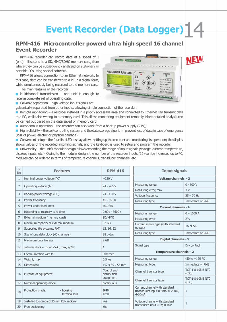
Event Recorder (Data Logger)RPM-416 Microcontroller powerd ultra high speed 16 channel Event Recorder
RPM-416 recorder can record data at a speed of 1 (one) millisecond to a SD/MMC/SDHC memory card, from where they can be subsequently analyzed on stationary or portable PCs using special software.
RPM-416 allows connection to an Ethernet network. In this case, data can be transferred to a PC in a digital form, while simultaneously being recorded to the memory card.
The main features of the recorder:Multichannel transmission – one unit is enough to
receive complete set of operating data;Galvanic separation – high voltage input signals are
galvanically separated from other inputs, allowing simple connection of the recorder;Remote monitoring – a recorder installed in a poorly accessible area and connected to Ethernet can transmit data
to a PC, while also writing to a memory card. This allows monitoring equipment remotely. More detailed analysis can be carried out based on the data saved on memory card;
Autonomous operation – the recorder can also work from a backup power supply (24V);High reliability – the self-controlling system and the data storage algorithm prevent loss of data in case of emergency
(loss of power, electric or physical damage);Convenient setup – the four-line LED display allows setting up the recorder and monitoring its operation; the display
shows values of the recorded incoming signals, and the keyboard is used to setup and program the recorder.Universality – the unit’s modular design allows expanding the range of input signals (voltage, current, temperature,
discreet inputs, etc.). Owing to the modular design, the number of the recorder inputs (16) can be increased up to 40. Modules can be ordered in terms of temperature channels, transducer channels, etc.
S.No Features RPM-416
1 Nominal power voltage (AC) ~220 V
2 Operating voltage (AC) 24 - 265 V
3 Backup power voltage (DC) 24 - 110 V
4 Power frequency 45 - 65 Hz
5 Power under load, max 10.0 VА
6 Recording to memory card time 0.001 - 3600 s
7 External medium (memory card) SD/MMC
8 Maximum capacity of external medium 32 GB
9 Supported file systems, FAT 12, 16, 32
10 Size of one data block (40 channels) 88 bytes
11 Maximum data file size 2 GB
12 Internal clock error at 25ºС, max, s/24h 1
13 Communication with PC Ethernet
14 Weight, max 0.5 kg
15 Dimensions 157 х 85 х 55 mm
16 Purpose of equipmentControl and distribution equipment
17 Nominal operating mode continuous
18 Protection grade: - housing - terminal bus
ІР40IP20
19 Installed to standard 35 mm DIN rack rail Yes
20 Free positioning Yes
Input signals
voltage channels - 3
Measuring range 0 - 500 V
Measuring error, max 3 V
Voltage frequency 25 – 70 Hz
Measuring type Immediate or RMS
Current channels - 4
Measuring range 0 – 1000 A
Measuring error 2%
Current sensor type (with standard output) 1A or 5A
Measuring type Immediate or RMS
Digital channels – 5
Signal type Dry contact
Temperature channels – 2
Measuring range -30 to +120 ºС
Measuring type Immediate or RMS
Channel 1 sensor type ТСТ-1-8-10k-B NTC (633)
Channel 2 sensor type ТСТ-1-8-10k-B NTC (633)
Current channel with standard trasnsducer input 0-5mA, 0-20mA, 4-20mA
1
Voltage channel with standard transducer input 0-5V, 0-10V 1

Automatic Healthy Phase Selector
PEF-301 Digital automatic phase selector (microcontroller based single phase automatic load transfer device)
The device serves to enhance the power supply reliability for
single phase consumers, and to protect them from inadmissible voltage
faults and fluctuations. It is designed to supply industrial/ household
single-phase 220-240V/50Hz load from three phase, four wire mains
3 x 230 + N in order to maintain uninterrupted power supply of essential
single phase loads and protect them against un-allowable voltage variations
in the mains. Depending on the voltage availability and quality in the main
phase (the priority is set to Line 1), the device selects the best healthy phase
and rapidly switches the single phase load to the phase selected. When the
initial phase voltage parameters are restored, PEF-301 may switch the load
back with the user defined time delay or remain operating on the line to
which it transferred the load. It protects any load up to 3.5 kW (16A) – directly by means of the relay output
terminals, over 3.5 kW – via magnetic contactors of appropriate rated power. PEF-301 is widely used with
uninterruptible power systems in applications such as communication and telecommunication, cable TV, access
control systems, countryside and suburban construction, alarm illumination and signalization schemes and a
great variety of other applications.
Scheme Awhen power load is less than 16A
Scheme Bwhen power load is more than 16A - additional contractors should be installed to commutate the corresponding power load
L1L2L3N
K3
L1L2L3N
K2
K1
1 2 3 4 5 6
1 2 3 4 5 6
L1 L2 L3 FAULT
L1 L2 L3 7 8 9 10 11 12
PEF-301Umin(V) Umax(V) Ton(sec) Tr(sec)
100 125 300 50 50 200
175 230 250 300 1 600 5
L1 L2 L3 FAULT
L1 L2 L3 7 8 9 10 11 12
PEF-301Umin(V) Umax(V) Ton(sec) Tr(sec)
100 125 300 50 50 200
175 230 250 300 1 600 5
LOAD AC ~240V
LOAD AC ~240V 16A
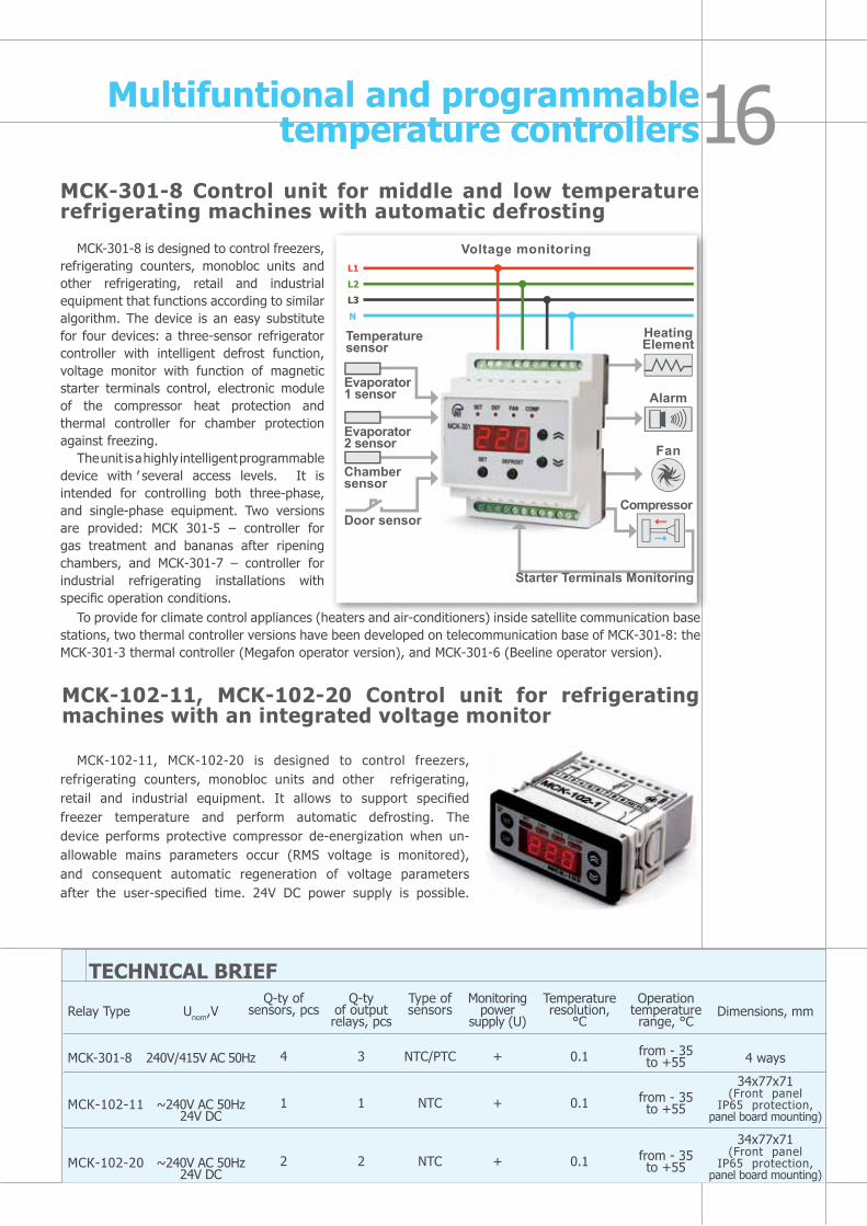
MCK-301-8 Control unit for middle and low temperature refrigerating machines with automatic defrosting
MCK-301-8 is designed to control freezers, refrigerating counters, monobloc units and other refrigerating, retail and industrial equipment that functions according to similar algorithm. The device is an easy substitute for four devices: a three-sensor refrigerator controller with intelligent defrost function, voltage monitor with function of magnetic starter terminals control, electronic module of the compressor heat protection and thermal controller for chamber protection against freezing.
The unit is a highly intelligent programmable device with several access levels. It is intended for controlling both three-phase, and single-phase equipment. Two versions are provided: МСК 301-5 – controller for gas treatment and bananas after ripening chambers, and МСК-301-7 – controller for industrial refrigerating installations with specific operation conditions.
MCK-102-11, MCK-102-20 Control unit for refrigerating machines with an integrated voltage monitor
МСК-102-11, МСК-102-20 is designed to control freezers, refrigerating counters, monobloc units and other refrigerating, retail and industrial equipment. It allows to support specified freezer temperature and perform automatic defrosting. The device performs protective compressor de-energization when un-allowable mains parameters occur (RMS voltage is monitored), and consequent automatic regeneration of voltage parameters after the user-specified time. 24V DC power supply is possible.
To provide for climate control appliances (heaters and air-conditioners) inside satellite communication base stations, two thermal controller versions have been developed on telecommunication base of МСК-301-8: the МСК-301-3 thermal controller (Megafon operator version), and МСК-301-6 (Beeline operator version).
Multifuntional and programmable temperature controllers
TECHNICAL BRIEF
Voltage monitoring
HeatingElement
Alarm
Fan
Compressor
Starter Terminals Monitoring
Door sensor
Chamber sensor
Evaporator 1 sensor
Evaporator 2 sensor
Temperature sensor
Relay Type
MCK-301-8
МСК-102-11
МСК-102-20
Unom,V
240V/415V AC 50Hz
~240V AC 50Hz24V DC
~240V AC 50Hz24V DC
Q-ty of sensors, pcs
4
1
2
Q-tyof output relays, pcs
3
1
2
Type ofsensors
NTC/PTC
NTC
NTC
Monitoring power
supply (U)
+
+
+
Temperature resolution,
°C
0.1
0.1
0.1
Operation temperature range, °С
from - 35to +55
from - 35to +55
from - 35to +55
Dimensions, mm
4 ways
34x77x71(Front panel
IP65 protection,panel board mounting)
34x77x71(Front panel
IP65 protection,panel board mounting)
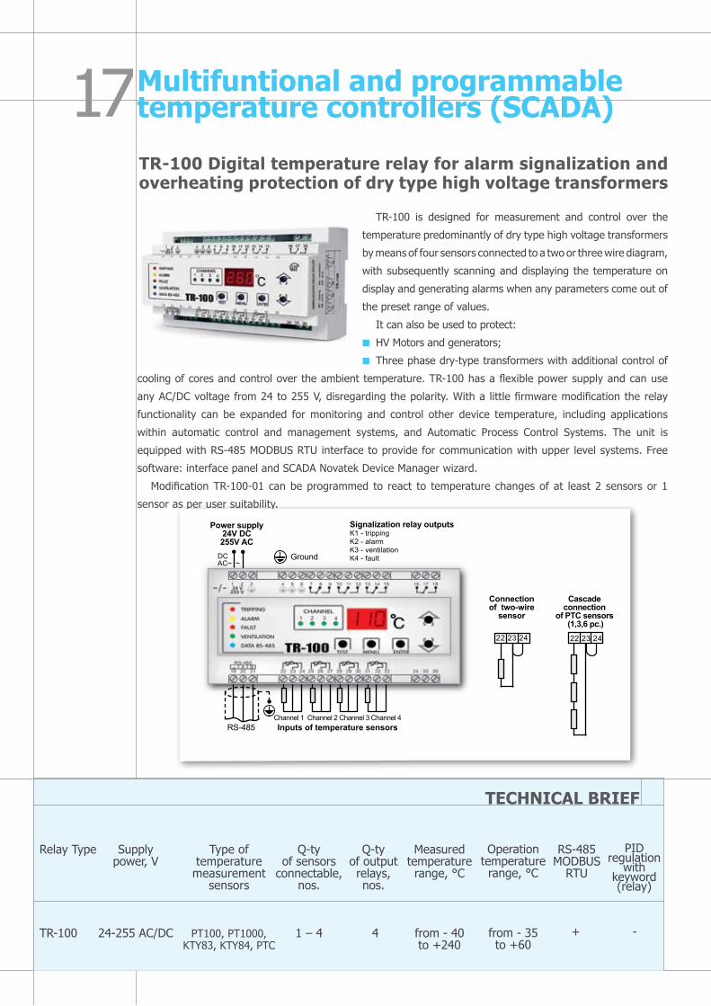
TR-100 is designed for measurement and control over the
temperature predominantly of dry type high voltage transformers
by means of four sensors connected to a two or three wire diagram,
with subsequently scanning and displaying the temperature on
display and generating alarms when any parameters come out of
the preset range of values.
It can also be used to protect:
HV Motors and generators;
Three phase dry-type transformers with additional control of
cooling of cores and control over the ambient temperature. TR-100 has a flexible power supply and can use
any АС/DС voltage from 24 to 255 V, disregarding the polarity. With a little firmware modification the relay
functionality can be expanded for monitoring and control other device temperature, including applications
within automatic control and management systems, and Automatic Process Control Systems. The unit is
equipped with RS-485 MODBUS RTU interface to provide for communication with upper level systems. Free
software: interface panel and SCADA Novatek Device Manager wizard.
Modification TR-100-01 can be programmed to react to temperature changes of at least 2 sensors or 1
sensor as per user suitability.
Multifuntional and programmable temperature controllers (SCADA)
TECHNICAL BRIEF
TR-100 Digital temperature relay for alarm signalization and overheating protection of dry type high voltage transformers
Q-tyof sensors
connectable,nos.
1 – 4
Relay Type
TR-100
Supplypower, V
24-255 AC/DC
Type of temperature measurement
sensors
РТ100, PT1000, KTY83, KTY84, PTC
Q-tyof output relays,nos.
4
Measured temperature range, °C
from - 40to +240
Operation temperature range, °С
from - 35to +60
RS-485 MODBUS
RTU
PID regulation
withkeyword(relay)
Signalization relay outputsK1 - trippingK2 - alarmK3 - ventilationK4 - faultDC
AC~ ~
Cascadeconnection
of PTC sensors (1,3,6 pc.)
22 23 24
Connectionof two-wire
sensor
Ground
Channel 1 Channel 2 Channel 3 Channel 4Inputs of temperature sensorsRS-485
Power supply24V DC255V AC
+ -
22 23 24
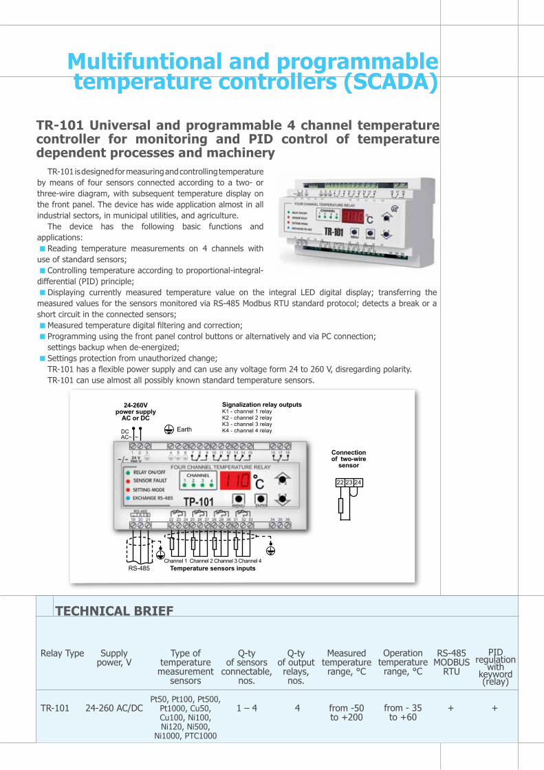
TR-101 is designed for measuring and controlling temperature by means of four sensors connected according to a two- or three-wire diagram, with subsequent temperature display on the front panel. The device has wide application almost in all industrial sectors, in municipal utilities, and agriculture.
The device has the following basic functions and applications:
Reading temperature measurements on 4 channels with use of standard sensors;
Controlling temperature according to proportional-integral-differential (PID) principle;
Displaying currently measured temperature value on the integral LED digital display; transferring the measured values for the sensors monitored via RS-485 Modbus RTU standard protocol; detects a break or a short circuit in the connected sensors;
Measured temperature digital filtering and correction;Programming using the front panel control buttons or alternatively and via PC connection; settings backup when de-energized;Settings protection from unauthorized change;TR-101 has a flexible power supply and can use any voltage form 24 to 260 V, disregarding polarity.TR-101 can use almost all possibly known standard temperature sensors.
TR-101 Universal and programmable 4 channel temperature controller for monitoring and PID control of temperature dependent processes and machinery
TECHNICAL BRIEF
Q-tyof sensors
connectable,nos.
1 – 4
Relay Type
TR-101
Supplypower, V
24-260 AC/DC
Type of temperature measurement
sensors
Pt50, Pt100, Pt500, Pt1000, Cu50, Cu100, Ni100, Ni120, Ni500,
Ni1000, PTC1000
Q-tyof output relays,nos.
4
Measured temperature range, °C
from -50to +200
Operation temperature range, °С
from - 35to +60
RS-485 MODBUS
RTU
PID regulation
withkeyword(relay)
+ +
Multifuntional and programmable temperature controllers (SCADA)
Signalization relay outputsK1 - channel 1 relayK2 - channel 2 relayK3 - channel 3 relayK4 - channel 4 relayDC
AC~ ~
22 23 24
Connectionof two-wire
sensor
Earth
Channel 1 Channel 2 Channel 3 Channel 4Temperature sensors inputsRS-485
24-260V power supply
AC or DC

Microcontroller and IGBT based transformer-less voltage stabilizers (patented new technology)
LEGAT-15 1.5 kVА
LEGAT-35 3.5 kVА
LEGAT-656.5 kVА
LEGAT-150 15 kVА
Advantages:
Unique transformerless scheme of voltage stabilization and unique unbeatable characteristics (patented)
Input voltage operation range 90-300 VOutput voltage smooth and stepless
regulationLow mass/dimensions parameters
Basic Technical Parameters:
Output voltage regulation accuracy not less than 1.5 %. Feature of output voltage regulation within range of 180-240 V (selectable), in 1 Volt increments. Start time regulation within range of 3-999 sec. Rate of response to abrupt variation of input voltage less than 0.05 sec. Availability of input and output filters that effectively level the circuit interference. Visual display of input/ output voltage as well as regulator load rate. Protection against current overload, short circuit, overheating, Circuit fault type indication. The regulator allows connecting any types of loads active and reactive.
LEGAT-5 0.5 kVА
Innovative, ultra fast voltage stabilization system
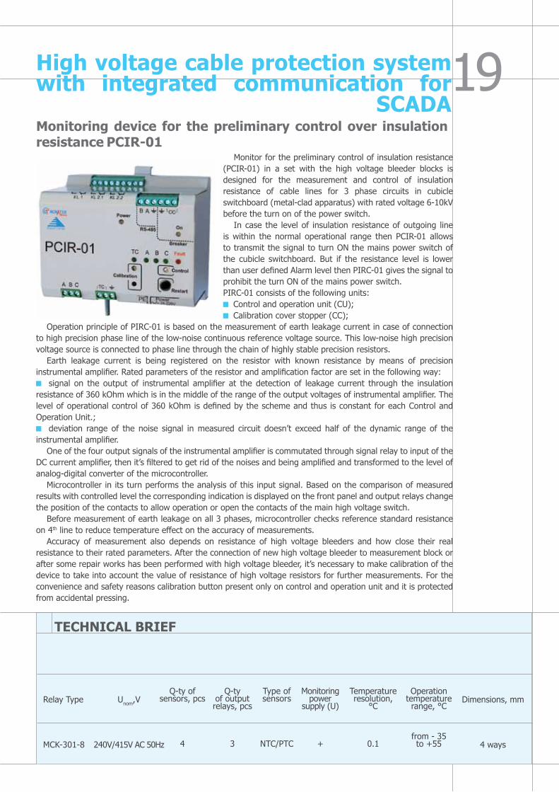
Monitoring device for the preliminary control over insulation resistance PCIR-01
Monitor for the preliminary control of insulation resistance (PCIR-01) in a set with the high voltage bleeder blocks is designed for the measurement and control of insulation resistance of cable lines for 3 phase circuits in cubicle switchboard (metal-clad apparatus) with rated voltage 6-10kV before the turn on of the power switch.
In case the level of insulation resistance of outgoing line is within the normal operational range then PCIR-01 allows to transmit the signal to turn ON the mains power switch of the cubicle switchboard. But if the resistance level is lower than user defined Alarm level then PIRC-01 gives the signal to prohibit the turn ON of the mains power switch.PIRC-01 consists of the following units: Control and operation unit (CU); Calibration cover stopper (CC);
Operation principle of PIRC-01 is based on the measurement of earth leakage current in case of connection to high precision phase line of the low-noise continuous reference voltage source. This low-noise high precision voltage source is connected to phase line through the chain of highly stable precision resistors.
Earth leakage current is being registered on the resistor with known resistance by means of precision instrumental amplifier. Rated parameters of the resistor and amplification factor are set in the following way: signal on the output of instrumental amplifier at the detection of leakage current through the insulation
resistance of 360 kOhm which is in the middle of the range of the output voltages of instrumental amplifier. The level of operational control of 360 kOhm is defined by the scheme and thus is constant for each Control and Operation Unit.; deviation range of the noise signal in measured circuit doesn’t exceed half of the dynamic range of the
instrumental amplifier.One of the four output signals of the instrumental amplifier is commutated through signal relay to input of the
DC current amplifier, then it’s filtered to get rid of the noises and being amplified and transformed to the level of analog-digital converter of the microcontroller.
Microcontroller in its turn performs the analysis of this input signal. Based on the comparison of measured results with controlled level the corresponding indication is displayed on the front panel and output relays change the position of the contacts to allow operation or open the contacts of the main high voltage switch.
Before measurement of earth leakage on all 3 phases, microcontroller checks reference standard resistance on 4th line to reduce temperature effect on the accuracy of measurements.
Accuracy of measurement also depends on resistance of high voltage bleeders and how close their real resistance to their rated parameters. After the connection of new high voltage bleeder to measurement block or after some repair works has been performed with high voltage bleeder, it’s necessary to make calibration of the device to take into account the value of resistance of high voltage resistors for further measurements. For the convenience and safety reasons calibration button present only on control and operation unit and it is protected from accidental pressing.
TECHNICAL BRIEF
Relay Type
MCK-301-8
Unom,V
240V/415V AC 50Hz
Q-ty of sensors, pcs
4
Q-tyof output relays, pcs
3
Type ofsensors
NTC/PTC
Monitoring power
supply (U)
+
Temperature resolution,
°C
0.1
Operation temperature range, °С
from - 35to +55
Dimensions, mm
4 ways
High voltage cable protection system with integrated communication for
SCADA
INDEXElectrical circuit fault protection multifunctional relays: 1. Single phase voltage monitoring relays (DIN mounting for industrial use)
RN-111M RN-113
Single phase voltage relays (plug-socket & board mounting for domestic use) RN-101M plug-socket type; RN-102
2. Three phase multifunctional voltage monitoring relays (3-ph 3 wire & 3-ph 4 wire) RNPP-301 RNPP-302 RNPP-311M RNPP-311
Multifunctional and programmable astro timers:3. Multifunctional time delay relays (2 Channel)
REv-201 (6 modifications) REv-201M (4 functions: time delay, pulse timer, cyclic timer, star-delta)
4. Programmable yearly timer with ASTRO functions with external Photo sensor and Voltage protection
REv-3025. Programmable weekly timer with in-built Photo sensor and Voltage protection
RN-16TM
Process control timer:6. Sequential cum Combination Timer
TK-415 (NEW)Numeric power factor controller:7. Three Phase 6 Stage Power Factor Correction Relay
KRM-136 (NEW)
Numeric motor protection relays:8. Asynchronous motor protection device having earth leakage and winding insulation level protection
UBZ-301 (5A – 50A) UBZ-301 (10A – 100A) UBZ-301 (63A – 630A)
9. Numeric motor protection device with RS232 & RS485 Modbus RTU communication for SCADA
UBZ-30210. Numeric motor protection relay (96 x 96 Flush mounting) with communication UBZ-304 (NEW)11. Single phase pump-motor starter cum protection unit
UBZ-115 (upto 25A) (NEW) UBZ-118 (upto 12A) (NEW)
Numeric power management system (demand controller) with integrated real time monitoring facility:12. Power management system with RS232 & RS485 Modbus RTU communication for SCADA
OM-310
Overload relays with auto reset timers and integrated digital display:13. Current overload relay and Power limiter with built-in CT and auto reset delay
RMT-101 OM-110
Event Recorder (data logger):14. Sixteen channels ultra high speed event recorder (Data Logger)
RPM-416 (NEW)
Automatic phase selector and auto transfer switch:15. Automatic phase selector cum auto transfer switch with delay timers
PEF-301
Digital temperature controllers and scanners: 16. Temperature controller for refrigerating equipments, heaters and air-conditioning systems
MCK-301-8 (refrigerators) MCK-301-6 (air-conditioning systems) MCK-102-11/ 20
17. Digital temperature controllers with RS485 Modbus RTU communication for SCADA
TR-100 (dry type transformer and HV motor applications) TR-101 (4 ch. PID controller)
Innovative, ultra fast voltage stabilization system:18. Microcontroller and IGBT based transformer-less voltage stabilizer with precise controllable output voltage
LEGAT series (0.5 kVA, 1.5 kVA, 3.5kVA, 6.5 kVA, 15 kVA)
High voltage cable protection system with integrated RS-485 Modbus communication for SCADA: 19. Monitoring device for the preliminary control over insulation resistance
PCIR-01
www.novatek-electro.com

Informationprovidedinthiscatalogueissubjecttochangeasperthefuturedevelopmentsmadebythecompanytoenhancethequalityanddurabilityoftheproducts.Novatek-ElectroLtd.retainsallrightsandcopyrightsofthedesignsandproductshighlightedherewith.
Global officesRESEARCH AND DEvELOPMENT CENTRE:
Novatek-Electro Ltd.59, Admirala Lazareva Street
Odessa - 65007, UkrainePhone: +38 048 738-00-28Mobile: +38 067 484-59-31
Fax: +38 048 234-36-73E-mail: [email protected]
NOvATEK ELECTRO (INDIA) PvT. LTD.C-30, Patparganj Industrial Area, 1st floor
Delhi – 110092, IndiaTel: +91 11 42143253Fax: +91 11 43010600
[email protected]@novatek-electro.com
http://www.novatek-electro.com/en