notes on segmented bowl constructionjlrodgers.com/pdf/segmented_bowl_const.pdf · notes on...
TRANSCRIPT

NOTES ON SEGMENTED BOWL CONSTRUCTION
PREPARING FOR SEGMENTED TUNING Major Equipment Here are the necessary and “nice to have” equipment requirements:
• Variable speed lathe, firmly mounted • Thickness sander for flattening glued up rings (nice to have) • 6 x 9 belt/disc sander • Drill press or other items to use as a glue press
Cutting sled In order to cut accurate segments you will require a fixture that accurately cuts the desired angle repeatedly, allows for accurate segment edge length measurement, and provides safety when cutting smaller pieces. For detailed information on building a cutting sled download complete instructions from either of the following sites:
Kevin Neely’s Turned Wood www.turnedwood.com Verified Software www.segmentedturning.com
Sanding board Construct this item from a piece of hardwood ¾ x 3 x 16 inches. Joint one face and edge flat and perpendicular, attached a strip of 80 grit sandpaper with contact cement. This will be used to square each ring to the lathe axis as the vessel is assembled.
Supplies Here is a list of items you will need before beginning:
• 60 – 80 Tooth finish cut blade for your table saw • Selection of hose clamps (6-8 various lengths) • Glue up board and paste wax • A minimum of two 3 inch face plates with hardwood glue blocks attached • Titebond II glue • Straight edge for checking rings • Disk/belt sander for correcting rings and flattening rings w/ 80grit belt • ¼ inch grid graph paper, ruler and compass
Tools In addition to your lathe you will require a minimum of turning tools – most of which you probably already have:
• Bowl gouge, ½ - ¾ inch for turning the exterior and interior of the vessel • Detail gouge for adding features to the foot • Large (3/8 inch thickness) bowl scraper for cleaning up inside • Calipers for determining wall thickness • Selection of cloth sanding strips (80, 120, 180, 220, 320 grits) • One Way Live Center System with an adaptor to match your lathe’s headstock
thread. (This allows for centering and supporting one of the faceplates used at the tailstock end of your lathe.)
• Jumbo Jaws for your chuck or another means of centering the rings being glued to the vessel

2
DESIGN You can’t do a segmented vessel without a drawing and a plan. You need the drawing in order to purchase the lumber require, cut segments to the proper size, and assemble a vessel with adequate wall thickness. Here is what is required:
• Make full size drawing on graph paper. Draw in all details. Make a detailed drawing of feature rings if one is used.
• Determine the wood species to be used, Decide the of number of segments in each ring.
• Make a cut list by determining the specifications of segments in each ring: height, width, and segment edge length. o Use convenient software for a faster and foolproof result. Software ranges from
shareware (provided in class) to approximately $100.00; a list of vendors is included in the appendix.
o Alternatively, make a full scale drawing, determine the necessary ring overlap for gluing) inside and outside dimensions of each ring), draw each ring full scale and measure the needed wood width and segment edge length. Record this information in a table.
• Calculate amount of wood needed for each ring. Don’t forget the saw kerf of 1/8 inch for each cut.
• If the pattern is complicated, consider making a prototype from less expensive wood first.
PREPPING WOOD • Joint one face and edge of wood to 90 degrees to each other, then make the face
and edge parallel • Cut to approximate length for each ring from your drawing (add 20% to allow safe
handling) Label each piece as you go. • Rip to the desired width for each ring starting with the widest width ring first. • Resaw to correct thickness if needed.
CUTTING SEGMENTS • Using the cutting sled on your table saw, cut segments to length • Cut an extra segment, or two, just in case there is an error in one piece. • Dry clamp using hose clamps. Hold ring up to light and check for snug fit.
o If light shows through on the outside edges of the ring, increase the angel of the cut.
o If light shows through on the inside edges of the ring, decrease the angel of the cut.
• If you don’t have a way of cutting the pieces accurately, you can cut them close to the dimension and sand every piece on a disc sander by making and using a accurate sanding jig.
• If the pieces don’t fit before gluing, they won’t fit after gluing. Spend the time to make them fit now, or the piece will never look good.
GLUING UP RINGS • Use a clean flat surface; melamine or Formica is good because glue doesn’t stick. If
you use wood, wax it thoroughly • Apply a thin coat of glue to each segment edge and clamp the ring loosly in your
hose clamp • Tap pieces down with a mallet to make sure they are flush. • Tighten the clamp snugly. • Wipe off any excess glue from the faces of the ring and set aside to dry. • When dry remove the clamps and true up one face of that ring, If you have a belt

3
sander that will work if you keep the ring moving and check with calipers for uniform thickness. Alternately, temporarily attach the ring on a flattened faceplate; true up the outer surface of ring and finish with the sanding board.
• When minor errors are seen in the dry fit you can still proceed it the following way: o Place a small piece of veneer between segments 6 and 7 and between segments
12 and 1. o Glue all other segments NOT THOSE WITH THE VENEERS. o Band clamp ad allow glue to dry as usual o Remove band clamp, the rings will be in two halves. o Sand each half on a belt sander until flat. o Glue the two halves together and put on the band clamp; they will mow be flush
ASSEMBLING THE BOWL
• Use a waste block on a faceplate for mounting the bowl. True up the waste block with the sanding board before attaching anything!
• Center the base of the bowl on the waste block and glue it in place. Use the tailstock to help with centering the base. Protect the ways of the lathe from wet glue, it will rust the lathe.
• When dry, true up the face of the base and round the outside. Do not reduce the size as the base needs to support the rest of the construction during turning.
• Center the first ring on the base and glue it in place. Hold it firmly in place otherwise the rings can slide or separate. Add appropriate clamps to assure a good, tight joint. When dry, turn the outside till round and true the face as done above.
• Continue with each ring until you have reached the top of your bowl or ½ the height of a hollow vessel. Make sure to stagger the joints.
• If you are building a hollow vessel, construct the other ½ of the vessel on the second faceplate starting with the top ring and working downward towards the center. If you are making a closed form, it is easier and quicker to turn the top and bottom separately. You can work on both ends at the same time and glue them in the middle. This makes for easier hollowing and sanding.
Centering Rings at glue up There are several methods to centering the additional rings being added to the vessel. The more “trial and error” the method the thicker the rings need to be made to allow for assembly errors. Here are some of the ways to align the next rings:
• Eyeball o Align the ring with a feeler gauge to measure around the edge for concentricity. A
pencil or ruler will do. When the ring is completely centered and rotated for the “bricking” or staggered alignment, the points of the added ring’s joints will all align with the center of the preceding segments. If they do not each align, then the ring is not centered.
o Plan for an addition to the planned wall thickness to allow for potential of alignment errors. A planned wall thickness of ½ - ¾ inch may be sufficient.
o Each ring must be turned round and flattened before the next ring is added to prevent error associated with compounding creep in assembly.
• Alignment cone o Construct a 20 – 30 degree cone that can be inserted into the tail stock Morris
taper. The surface should be very smooth and sealed o Attach the vessel’s faceplate to the lathe in the normal manner and cover the
ways to prevent rust from dripping glue. o Place the cone in the tail stock o Glue the next flattened ring and use the cone to center it against the vessel. o Tighten the tailstock to provide glue up pressure
• Chuck with “Jumbo Jaws” o Purchase from OneWay Manufacturing Company
4
OneWay Live Center system OneWay Live Center adapter for your hears stock’s thread
o Purchase from your chuck manufacturer or construct a set of large jaws suitable for supporting a bowl’s rim
o Grab the ring to be mounted in these jaws and assemble as in the methods above
o In larger rings it will be necessary at add clamps around the circumference to press the added ring to the former portion of the vessel as the aluminum “jumbo jaws” will deform to some degree not providing even pressure at the outside rim.
Turning the vessel
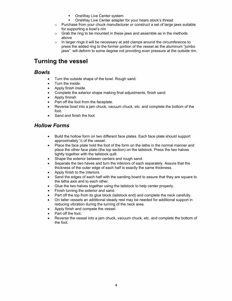
Bowls • Turn the outside shape of the bowl. Rough sand. • Turn the inside. • Apply finish inside. • Complete the exterior shape making final adjustments, finish sand • Apply fininsh • Part off the foot from the faceplate. • Reverse bowl into a jam chuck, vacuum chuck, etc. and complete the bottom of the
foot. • Sand and finish the foot
Hollow Forms
• Build the hollow form on two different face plates. Each face plate should support approximately ½ of the vessel.
• Place the face plate hold the foot of the form on the lathe in the normal manner and place the other face plate (the top section) on the tailstock. Press the two halves tightly together with the tailstock quill.
• Shape the exterior between centers and rough sand. • Separate the two haves and turn the interiors of each separately. Assure that the
thickness of the outer edge of each half is exactly the same thickness. • Apply finish to the interiors. • Sand the edges of each half with the sanding board to assure that they are square to
the lathe axis and to each other. • Glue the two halves together using the tailstock to help center properly. • Finish turning the exterior and sand. • Part off the top from its glue block (tailstock end) and complete the neck carefully. • On taller vessels an additional steady rest may be needed for additional support in
reducing vibration during the turning of the neck area. • Apply finish and compete the vessel. • Part off the foot. • Reverse the vessel into a jam chuck, vacuum chuck, etc. and complete the bottom of
the foot.

5
Appendix
Local wood sources Macbeath Hardwoods, Berkeley
General wood supplier of a large selection of domestic and exotic hardwoods – browse the warehouse
Woods Unlimited, San Leandro Large selection of Ebony and blackwood Sources for supplies and equipment
• Craft Supplies USA, 800-551-8876, www.woodturnerscatalog.com o Most complete suppliers to wood turners in the USA
• Direct Safety, 800-528-7405, www.directsafety.com o Safety supplies, dust masks, etc.
• Klingspor’s Woodworking Shop, 800-228-0000, www.woodworkingshop.com o Sanding and finishing product, importer of German sandpapers
• OneWay Manufacturing, 800-565-7288, www.oneway.ca o Manufacturers of lathes and lathe accessories
• Packard Woodworks, 800-683-8876, www.packardwoodworks.com o Woodturning supplies tools, equipment, supplies
• Rockler Woodworking, 925-521-1800, www.rockler.com o General woodturning supplies, lumber, tools, equipment
• The Cutting Edge, 800-790-7980,www.cuttingedgetools.com o Turning and Carving tools
• Tool Crib (Amazon), 200-635-5140, www.amazon.com o Tools, equipment mail order
• Treeline, 800-598-2743, www.treelineusa.com o Carving tools
• Woodcraft of Dublin, 925-875-9988, www.woodcraft.com o General woodturning supplies, lumber, tools, equipment
Books Segmented Turning, A Complete Guide, Ron Hampton, Guild of Master Craftsmen, 2003 Segmented Turning, A Good Start, Bill Kandler,Verified Software, 2004 Segmented Turning, William Smith, Schiffer Publishing Ltd., 2002 The Art of Segmented Wood Turning, Malcolm Tibbetts, Linden Publishing, to be released 2005 Woodturning with Ray Allen, Ray Allen & Dale Nish, Fox Chapel Publishing, 2004 Laminated Designs in Wood, Clarence Rannefeld, Lark Books, 1998 Southwest Pottery – Anasazi to Zuni, Allen Hayes & John Blom, Northland Publishing, 1996 Fine Woodworking on Faceplate Turning, Taunton Press, 1987

6
Articles The Lost Wood Process http://www.ovwg.org/New-OVWG-Site/Techniques/Lost%20Wood%20Turning%20Process.htm
Software suppliers Stave calculations http://stavecalc.logiztix.net/ Simple segment calculations and lots of help on the processes http://turnedwood.com/ Calculations for open segment work http://texasgadgets.com/ The most complete program & difficult to manipulate http://verifiedsoftware.com/goodturns/ This is the one I use http://woodturnerpro.com/ General woodworking software including layout http://www.woodbin.com/
Veneer Sources Wood cost comparisons http://www.verifiedsoftware.com/goodturns/woodcosts.htm Constantine’s http://www.constantines.com/ Certainly Wood www.certainlywood.com Hearn Hardwoods http://www.hearnehardwoods.com/ Woodworkers Resource http://www.woodworkerssource.net/index.html
Untested sites World panels www.worldpanel.com/WoodVeneers.htm Dodge Veneers http://www.doogeveneers.com/ Exotic Wood * http://www.exotic-wood-online.com/ Form Wood Industries http://www.formwood.com/index.htm West Penn Hardwoods http://www.westpennhardwoods.com/ Source for inlays http://www.inlays.com/ Saurers & Company http://www.sveneers.com/

7
Segment Edge Length Estimation Table
Number of segments 6 8 12 16 24
Ring Diameter Segment Edge Length
1 9/16 7/16 ¼ 3/16 1/8 1.5 7/8 5/8 3/8 5/16 3/16 2 1 1/8 13/16 5/16 3/8 ¼
2.5 1 7/16 1 1/16 11/16 ½ 5/16 3 1 ¾ 1 ¼ 13/16 5/8 3/8
3.5 2 1 7/16 15/16 11/16 7/16 4 2 5/16 1 11/16 1 1/16 13/16 ½
4.5 2 5/8 1 7/8 1 3/16 7/8 9/16 5 2 7/8 2 1/16 1 5/16 1 11/16
5.5 3 316 2 ¼ 1 ½ 1 1/8 ¾ 6 3 7/16 2 ½ 1 5/8 1 3/16 13/16
6.5 3 ¾ 2 11/16 1 ¾ 1 5/16 7/8 7 4 1/16 2 7/8 1 7/8 1 3/8 15/16
7.5 4 5/16 3 1/8 2 1 ½ 1 8 4 5/8 3 5/16 2 1/8 1 9/16 1 1/16
8.5 4 15/16 3 ½ 2 ¼ 1 11/16 1 1/8 9 5 3/16 3 ¾ 2 7/16 1 13/16 1 3/16
9.5 5 ½ 3 15/16 2 9/16 1 7/8 1 ¼ 10 5 ¾ 4 1/8 2 11/16 2 1 5/16
10.5 6 1/16 4 3/8 2 13/16 2 1/16 1 3/8 11 6 3/8 4 9/16 2 15/16 2 3/16 1 7/16
11.5 6 5/8 4 ¾ 3 1/16 2 5/16 1 ½ 12 6 15/16 5 3 3/16 2 3/8 1 9/16
12.5 7 3/16 5 3/16 3 3/8 2 ½ 1 5/8 13 7 ½ 5 3/8 3 ½ 2 9/16 1 11/16
13.5 7 13/16 5 9/16 3 5/8 2 11/16 1 ¾ 14 8 1/16 5 13/16 3 ¾ 2 13/16 1 13/16
14.5 8 3/8 6 3 7/8 2 7/8 1 15/16 15 8 11/16 6 3/16 4 3 2
15.5 8 15/16 8 7/16 4 1/8 3 1/16 2 1/16 16 9 ¼ 6 5/8 4 5/16 3 3/16 2 1/8
16.5 9 ½ 6 13/16 4 7/16 3 5/16 2 3/16 17 9 13/16 7 1/16 4 9/16 3 3/8 2 ¼
17.5 10 1/8 7 ¼ 4 11/16 3 ½ 2 5/16 18 10 3/8 7 7/16 4 13/16 3 9/16 2 3/8
18.5 10 11/16 7 11/16 4 15/16 3 11/16 2 7/16 19 11 7 7/8 5 1/16 3 ¾ 2 ½
19.5 11 ¼ 8 1/16 5 ¼ 3 7/8 2 9/16 20 11 9/16 8 5/16 5 3/8 4 2 5/8

8
Building A TS 15 Degree Segment Cutting Sled
• Stock required o 24 x 24 sheet of ½ inch quality plywood o Hardwood for miter guides o KD 2 x 4 x 48 inches for cross supports o ¾ x 3 x 24 inch hardwood for miter fence
• Prepare stock o Cut stock to size
1 each 18” x 24” ½” ply cut dead square 2 each ½ x ¾ x 24 inch strips for miter grove guides 1 each ¾ x 3 x 24 inch hardwood segment fence 1 each 2 x 4 x 24 inch rear cross support brace 1 each 2 x 2 x 24 inch front cross support fence
o Collect additional supplies 2 each 1 ½ bolts with head diameter less than ¾ with washers and nuts Wood screws 1 inch ¾ inch Forstner bit Glue Toggle clamp with ¾ inch mounting screws One each stick on measuring tape (RH) Fine ink pen Square Vernier calipers
• Assemble sled o Sand 18 x 24 base on both side o Place miter guides in TS miter slots on top of spacer (to raise them above TS
surface) o Bring TS fence to 12 inch setting, lock in place o Place glue on miter guides and set 18 x 24 on top aligned with fence o Add weight and allow glue to dry
• Add cross supports o Carefully align front and back cross support braces o Glue and clamp front and back cross support braces
• Add saw kerf o Clean up any glue and scrape slides until there is a smooth operation on the saw
table o Wax the back o Raise saw blade and cut a kerf through he rear cross support and 12 inches into
the sled • Mount hardwood segment fence
o Clamp Miter segment fence accurately in place using a protractor to set approximately 15 degree angle to saw kerf, clamp firmly
o Flip sled over side-to-side (read fence is still in the rear) and drill one hole in each miter guide through which to attach the hardwood segment fence
o RH hole is 4 inches from front edge of sled and LH hole is7.5 inches from front edge. Drill only through the hardwood miter guide
o Continue holes with smaller drill (diameter of the bolts) completely through clamped fence
• Complete segment fence assembly o Turn sled right side up remove the segment fence o Elongate one of the drilled holes to 1 inch long o Bolt segment fence in place readjusting accurately to 15 degrees o Add toggle clamp to the segment fence approximately 6 inches to the right of the
saw kerf o Cut a short strip of hardwood with the sled to use as a segment stop
• Calibrate sled o Set TS blade to an accurate 90 degrees vertical with a good straight edge

9
o Rip several strip of hardwood to 1 inch o Clamp stop in place with the toggle clamp o Carefully cut six segment using sled o Snugly assemble the six pieces against a straight edge and check; there should
be no gap If there is a gap on the outside of the semicircle of segments, the angle is
too oblique • Adjust the segment fence towards the rear of the sled (away
from the operator)to increase the angle If the gap on the inside of the semicircle, the angle is too acute
• Adjust the fence rearward (towards the operator) to decrease the angle
o Repeat by cutting another 6 segments and retesting o When the six segment test appears perfect, cut a set of 12 segments
Assemble a full ring by clamping the segments together with a hose clamp
Check for gaps Readjust fence as needed to decrease the gaps to zero
o When calibration is complete, screw segment fence firmly in place with several wood screws on both sides of the saw kerf
• Completing the project o Recut the stop with the newly calibrated sled o With vernier calipers, set the position of the stop at exactly 2 inches from the
right-most tooth of the saw blade, clamp firmly with the toggle clamp o At a convenient location on the stop, place a fine line with an ink pen and square o Align the stick-on measuring tape’s 2 inch mark with the line drawn on the stop o Stick the measuring tape in place
Rear of sled
Elongated hole with washer
Stop cut at 15 degrees

10
Causes of Error in Making Segmented Rings
• Table saw blade not set to a perfect vertical 90 degrees • TS blade not appropriate
o Dull o Not finish cut 60-80 tooth blade
• Miter guides running loosely in the miter slots causing shift in the sled • Stops slipping due to being clamped too loosely • Stop initial setting to segment edge length inaccurate • Saw dust accumulating on sled causes inaccurate cuts • Lumber inaccurately prepared before cutting
o Not flat o Edges not parallel and square to lumber faces o Lumber moved due to changing internal stresses
• Lumber not held tightly against fence and stop during cuts • Inaccurate drawing or cut list causing improper cuts
• Glue up not done on a flat surface • Band clamps not secured tightly • Ring not examined for cut errors prior to glue up • Errors not corrected at the half circle (flattened to 180 degrees) before
completing the 360 degree ring • Glue not allowed to dry before removing ring clamp • Ring not flattened to parallel faces • Vessel not checked for true as it is being assembled • New ring not clamped tightly to vessel as it is being assembled (especially
when veneers are added between rings)

11
TRIGONOMETRY FOR SEGMENTED TURNERS
Angle functions are useful in calculating the setup of sleds for specific angles. When accurately determined the calculations can set the segment fence precisely. The longer the measured line the more accurate the set up will be. To calculate the proper angle you need to use the appropriate trig function; here they are:
Sine = Opposite/ Hypotenuse Cosine = Adjacent/Hypotenuse Tangent = Opposite/ Adjacent
Angle Sine Cosine Tangent
30 degrees (6 sides) .5000 .8660 .5774
22.5 degrees (8 sides) .3827 .9239 .4142
18 degrees (10 sides) .3090 .9511 .3249
15 degrees (12 sides) .2588 .9659 .2679
11.25 degrees (16 sides) .1951 .9808 .1989
7.5 degrees (24 sides) .1305 .9914 .1317

12
Setting up a new segment fence
• Draw a horizontal line across the full 24 inch width of the sled. • Calculate the distance up the RH side of the sled by using the tangent of the desired
angle • Measure up the right hand side of the sled the exact number of inches from your
calculation and mark. • Draw a line from that mark to the beginning of the 24 inch horizontal line. • Align the segment fence to that line for the proper angle.
Tangent 15 degrees x 24 inches = RH length to calculate 0.2679 x 24 inches = 6.43 inches