notes mermaid marine - mermaid manufacturing guide using standard ... mermaid supplies pleasure boat...
TRANSCRIPT
NOTES
2651 Park Windsor Drive, Suite 203
Fort Myers, FL 33901
(239) 418-0535 (800) 330-3553
Fax: (239) 418-0538
E-mail: [email protected]
Website: http://www.mmair.com
INSTALLATION
&
OPERATIONS GUIDE
USING STANDARD THERMOSTATS
MERMAID MARINE
AIR CONDITIONING
TABLE OF CONTENTS
SECTION 1 (OVERVIEW)
A. Introduction to Mermaid
SECTION 2 (INSTALLATION and OPERATION)
A. Air Conditioner Installation
B. Operation
SECTION 3 (OPERATION and PROGRAMMING)
A. Digital, Programmable Thermostat (FX-1 Manual is separate)
SECTION 4 (PUMP RELAY BOX)
A. Introduction
B. Installation
SECTION 5 (MAINTENANCE and WINTERIZATION)
A. Maintenance
B. Winterization
SECTION 6 (THEORY of OPERATION and TROUBLE SHOOTING)
A. Theory of Operation
B. Trouble Shooting
FIGURES:
1. Typical Ducting and Venting Scheme
2. Operational Block Diagram
3. Typical Cooling Water Installation
4a. Wiring Diagram "Cool Only" Models
4b. Wiring Diagram "Electric Heat and Cool" Models
4c. Wiring Diagram "Reverse Cycle Heat and Cool" Models
5. Typical Bleed Off Valve Installation
NOTES
MERMAID MANUFACTURING OF SOUTHWEST FLORIDA, INC.
2651 PARK WINDSOR DRIVE, SUITE 203
FORT MYERS, FL 33901
(239) 418-0535 (800) 330-3553
FAX: (239) 418-0538
WWW.MMAIR.COM
SECTION 1
OVERVIEW
A. Introduction:
Congratulations!! You have just purchased one the most dependable
Marine Air Conditioners on the market today, a MERMAID.
Mermaid supplies pleasure boat owners, custom boat builders, yacht
brokers, boat dealers and marinas around the world with their marine
air conditioning needs.
Mermaid air conditioners are manufactured to the highest of quality
standards using only top of the line components and materials assem-
bled by long-term technicians. All of our air conditioners are modular-
ized, self contained, prewired, precharged and mounted on a solid foun-
dation of stainless steel. All of our air conditioning components, such
as the evaporator, compressor and condensing coil are manufactured in
the USA. All electrical parts are standard refrigeration components and
are available across the entire country, and around the world. Any four
wire 24Volt digital thermostat will operate any standard Mermaid air
conditioner.
Our standard electrical control box does not contain any printed circuit
boards or solder. All electrical connections are "snap on" color coded
wires, making part replacement simple and fast. The electrical box can
be unplugged for ease of assembly and service and the entire installa-
tion can be accomplished with standard shop tools. Our upgraded con-
troller uses state of the art electronics eliminating any contactor or relay
noises.
Don’t forget to see our NEW flush mount digital controller on our
website – www.mmair.com. Upgrades to this controller are availa-
ble at anytime.
Our warranty is also unsurpassed. For the first 5 years, the Mer-
maid factory warranty covers all issues with your air unit. After 5
years, any certified air conditioner technician, marine, household
or commercial, can service any Mermaid air conditioner model.
SECTION 2
INSTALLATION & OPERATION
A. AIR CONDITIONER INSTALLATION:
First, and of foremost importance, the air conditioner and electrical box must be in-
stalled in a non-explosive, dry environment. SEE THE FOLLOWING WARNING.
WARNING
IF THE AIR CONDITIONER OR ELECTRICAL BOX ARE PLACED IN AN
EXPLOSIVE ENVIRONMENT OR EXPOSED TO AN EXPLOSIVE ENVIRON-
MENT OR EXPLOSIVE MATERIALS, EXPLOSION COULD OCCUR RE-
SULTING IN SERIOUS INJURY OR DEATH AND/OR DESTRUCTION OF
THE BOAT. THIS COMPONENT DOES NOT MEET FEDERAL REQUIRE-
MENTS FOR IGNITION PROTECTION. DO NOT INSTALL IN SPACES CON-
TAINING GASOLINE ENGINES, TANKS, LPG/CPG CYLINDERS, REGULA-
TORS, VALVES OR FUEL LINE FITTINGS. FAILURE TO COMPLY MAY
RESULT IN INJURY OR DEATH.
Typical unit mounting spots are under the vee berth, under settee seats, in hanging lock-
ers, in cabinets or in outside dry lazzeretts and sail lockers. The selected spot must
accommodate the following eight requirements. Everything must fit in and/or be acces-
sible to the selected spot:
(a) The physical size of the unit and electrical box.
(b) Water in and out hoses.
(c) Electrical power cable for the unit and pump connections.
(d) Air ducting and air splitters.
(e) Mounting of the return air grill to insure the proper volume of return air.
(f) Access to the high pressure switch.
(g) Condensation removal.
(h) Thermostat installation and wiring.
IMPORTANT
READ THE ENTIRE INSTALLATION INSTRUCTIONS BEFORE YOU COM-
MIT TO CUTTING OR DRILLING ANY HOLES. REMEMBER " HOLES
ARE FOREVER". MEASURE, MEASURE, THEN MEASURE AGAIN BE-
FORE PICKING UP ANY TOOL WITH A SHARP EDGE.
IMPORTANT
LEAVE AMPLE EXCESS OF HOSE, WIRE AND DUCTING WHEN ROUTING
INTO THE AIR CONDITIONER MOUNTING COMPARTMENT TO ALLOW
FOR FINAL POSITIONING OF THE AIR CONDITIONER AFTER ALL IN-
STALLATION TASKS ARE COMPLETED.
LIMITED WARRANTY
APPLICABLE TO THE CONTINENTAL U.S. ONLY
If your air conditioner fails to function (due to a defect in material or workmanship)
within five years from the date of purchase, MERMAID MANUFACTURING OF
S.W. FL, INC. (hereafter “MERMAID”) will replace or repair (at MERMAID’S discre-
tion) any defective parts free of charge after written notice to MERMAID of your intent
to ship the air conditioner and after the air conditioner has been returned to MER-
MAID’S factory with transportation charges to the factory prepaid. MERMAID covers
shipping charges both ways for the first six months of the five year warranty. After that
six month period YOU are responsible for all shipping fees to get the unit TO the facto-
ry. Mermaid will cover the fee to ship it back to you. If your dehumidifier fails to func-
tion (due to defect in material or workmanship) within one year from the date of pur-
chase MERMAID will repair or replace at our discretion any defective parts free of
charge after the same intentions as listed above are followed. If any of the labeled
“Distributed Product” fails to function as expected, contact the Mermaid factory for
assistance in routing your call to the main manufacturer. Mermaid accepts no liability
for improperly handled or installed “Distributed Products.”
If your pump, thermostat, or FX-1 digital control fails to function within one year re-
spectively from the date of purchase, MERMAID will replace the pump, thermos-stat,
or FX-1 digital control free of charge after written notice to MERMAID of your intent
to ship the pump, thermostat, or FX-1 digital control and after the pump, thermostat, or
FX-1 digital control has been returned to MERMAID’S factory with the transportation
charges to the factory prepaid.
The five year and one year provision of this limited warranty shall be void if the air
conditioner, or dehumidifier has been damaged after sale, subjected to unreasonable or
abnormal use or operation, altered, repaired by anyone other than MERMAID without
the company’s consent, subjected to water flow (on the air conditioning unit) rates ex-
ceeding 500 G.P.H., wired with undersized wiring, or installed or used other than as
indicated in the installation and users’ guide. MERMAID is not responsible for the
installation or de-installation of units. MERMAID is NOT responsible for labor reim-
bursement .
MERMAID MAKES THIS LIMITED WARRANTY EXPRESSLY IN LIEU OF ALL
OTHER WARRANTIES, EXPRESSED OR IMPLIED, INCLUDING, BUT NOT
LIMITED TO, THE EXPRESSED WARRANTIES OF MERCHANTABILITY AND
BREACH OF ANY WARRANTY THE LIABILITY OF MERMAID SHALL BE
LIMITED TO REPAIRING OR REPLACING THE NONCONFORMING GOODS.
MERMAID SHALL NOT BE LIABLE FOR ANY OTHER DAMAGES, EITHER
DIRECT, INCIDENTAL OR CONSEQUENTIAL, REGARDLESS OF THEIR KIND
OR NATURE.
NON-TRANSFERABLE
We will now address each of the above eight requirements in detail:
1. Installing the Air Conditioner Unit:
AIR CONDITIONER DIMENSIONS
UNIT BTU WIDTH LENGTH HEIGHT
5,200 Cool Only 11.5 Inches 15 Inches 12.0 Inches
5,200 Reverse Cycle 12 Inches 18 Inches 12.0 Inches
6,500 11.5 Inches 16 Inches 12.0 Inches
9,000 11.5 Inches 16 Inches 12.0 Inches
12,000 13.0 Inches 19.75 Inches 14.25 Inches
16,500 13.5 Inches 19.75 Inches 14.25 Inches
24,000 17 Inches 23 Inches 16.75 Inches
The air conditioner needs to be mounted in an area where it will physically fit, as well
as accommodate a properly sized return air grill and any ducting or splitters (Wyes)
which would be attached to the air output collar. In addition, you need to insure there is
space for the water hoses to be connected.
The air conditioner must be securely mounted on a flat surface. If the sole of the boat
(cabin floor) cannot accommodate the size of the air conditioner base plate, a mounting
shelf or platform must be built. Typically the shelf will be made from 3/4 inch marine
grade plywood which can be either fiberglassed or mechanically attached to the boat’s
sole or superstructure. Never screw directly into the hull.
When attaching the unit to the sole of the boat, the superstructure or a fabricated mount-
ing shelf, always make absolutely positive that the length of the screws being used to
mount the unit will not engage the hull. If there is any question as to whether the hull
may be compromised, an alternative mounting method must be used or another mount-
ing spot must be located.
The electrical box, unlike the air conditioner, can be mounted in any attitude. It is at-
tached to the air conditioner by a detachable 40 inch electrical cable allowing it to be
mounted above the unit, on a side wall or bulkhead and, if needed, in a totally inverted
position.
IMPORTANT
IT IS NOT UNCOMMON IN AIR CONDITIONING SYSTEMS FOR CONDEN-
SATION LINES OR PANS TO BECOME BLOCKED OVER PROLONGED
USE. WHEN SELECTING THE ELECTRICAL BOX MOUNTING SPOT
MAKE SURE THAT IT IS NOT LOCATED WHERE CONDENSATION WA-
TER CAN COME IN CONTACT WITH IT SHOULD THE CONDENSATION
WATER OVER FLOW ITS PAN. NEVER PLACE THE ELECTRICAL BOX
BELOW THE AIR CONDITIONING UNIT.
WARNING
IF CONDENSATION WATER CONTACTS THE ELECTRICAL BOX ELEC-
TRICAL SHORTING COULD OCCUR CAUSING FIRE WHICH COULD RE-
SULT IN SERIOUS INJURY, DEATH AND/OR DESTRUCTION OF THE
BOAT.
We suggest that once you are satisfied that the unit and electrical box, along with all of
the other items required in the air conditioner compartment will fit, that you remove the
air conditioning unit and electrical box or cover them completely until all holes and
construction in the compartment are completed and the area cleanly vaccuumed.
2. Cooling water in and out:
All central marine air conditioning and heating units are water cooled. Cooling water is
provided to the air conditioner via a foot scoop, sea cock, water strainer and pump as-
sembly all of which are mounted below sea level. Typically the sea cock, water strain-
er and pump are installed remotely to the air conditioner (SEE FIGURE 3).
Water In:
Generally, in power boats, the sea cock will be installed in the engine compartment. In
sail boats, because of their more uniform draft characteristics, it is usually installed un-
der a settee seat or some other compartment more convenient to the air conditioner.
Water is then routed to the air conditioner from the pump via 5/8 inch marine water hose
(also known as ½” I.D. hose) where it is connected to the air conditioner condensing
coil's "water in" connection. Make sure that space is allowed around the unit to make
this connection. The water hose is easily kinked, restricting water flow. If needed, use
a hose barb 90 degree fitting to eliminate any kinking. (These can be found at any pvc
supply store).
An additional length of 5/8 inch marine hose (again, ½” I.D.) is connected to the con-
densing coil "water out" connection. Cooling water passes through the condensing coil
and routed through this hose to the "water out" thru-hull fitting which will be installed
above water level in the side of the boat’s hull (SEE FIGURE 3).
IMPORTANT
THE SEA COCK, WATER STRAINER AND WATER PUMP MUST BE IN-
STALLED BELOW SEA LEVEL. THE SEA WATER PUMP IS NOT SELF
PRIMING AND RELIES ON WATER SEEKING ITS OWN LEVEL ALONG
WITH THE HYDRAULIC PRESSURE OF THE BOAT TO ATTAIN PRIMING
OF THE PUMP.
WARNING
BEFORE DRILLING THE MOUNTING HOLE FOR THE SEA COCK THE
ENTIRE BOAT MUST BE OUT OF THE WATER. DRILLING THE SEA
COCK MOUNTING HOLE WITH THE BOAT IN THE WATER COULD
CAUSE EXTREME FLOODING AND SINK THE BOAT OR CAUSE SEVERE
WATER DAMAGE TO EQUIPMENT IN THE BOAT.
IMPORTANT
WHEN SELECTING THE SPOT FOR THE SEA COCK, BEFORE DRILLING
THE HOLE, MAKE SURE THAT THE PUMP AND WATER STRAINER CAN
BE INSTALLED IN THE SAME ADJACENT AREA AND REMAIN BELOW
SEA LEVEL. ALSO CHECK THE OPERATION OF THE BALL VALVE
SHUT OFF HANDLE ON THE SEA COCK FOR ANY POSSIBLE INTERFER-
ENCE ONCE INSTALLED.
When selecting your sea cock mounting spot, you should also try to select a spot where
the pump and water strainer are a maximum distance of 2 feet from the sea cock. We
realize that in some boats it is not possible to incorporate the two foot rule. However,
remember the closer you keep these three items together, the fewer pump priming prob-
lems will be experienced.
Once you are sure that all components will fit in the spot selected and remain below sea
level and the boat is totally out of the water, you are ready to cut the sea cock mounting
hole. (SEE WARNING ABOVE)
IMPORTANT
BEFORE CUTTING YOUR SEA COCK MOUNTING HOLE CHECK THE
OUTSIDE HULL IN THE AREA YOU WILL BE CUTTING TO MAKE SURE
THAT THERE ARE NO RIBS OR OTHER HULL VARIATIONS WHICH
WILL NOT ALLOW THE SEA COCK FOOT SCOOP TO MOUNT FLAT
AGAINST THE HULL. IF THERE IS ANY CONCERN, WHAT-SO-EVER,
DRILL A SMALL PILOT HOLE FIRST WHICH CAN BE EASILY SEALED IF
INTERFERENCE EXISTS.
If you are using a sea cock assembly furnished by Mermaid, we recommend that a 1-
1/16 inch hole saw be used to make this hole. If you are using a sea cock purchased
elsewhere, you must use the appropriate hole saw for that specific sea cock.
IMPORTANT
DRILL THE 1-1/16” SEA COCK MOUNTING HOLE AND PILOT HOLE AT
THE SAME ANGLE AS THE HULL. THIS WILL INSURE THAT THE FOOT
SCOOP LIES FLAT AGAINST THE HULL.
Once the sea cock hole is drilled, inspect the hole to determine if your boat has a
"corded" hull. That is, a hull not of solid fiberglass, but two layers of fiberglass separat-
ed by balsa or foam. When not properly sealed, “cording” acts like a wick, absorbing
sea water into the hull. If the hull is "corded," obtain a fiberglass sealing kit from your
local marine supplier to seal the cording before installing the sea cock, eliminating the
possibility of "water logging" your hull. This is also true of water out thru-hulls.
IMPORTANT
FAILURE TO SEAL A “CORDED” HULL MAY RESULT IN SERIOUS DAM-
AGE TO THE BOAT’S STRUCTURE.
Note: The threads on the foot scoop end about 3/8 of an inch from the actual foot
scoop. If after drilling the hole for the foot scoop you discover that your hull is thinner
than 3/8 inch, you will need to reinforce the hull with a 6” x 6” pad to “shim up” to
insure the nut tightens correctly. We usually use ¾ inch marine grade plywood to fash-
ion the pad. Apply fibreglass on both sides of the pad and affix to the inside of the hull.
After the fiberglass has cured, assuming that you had already drilled the hole for the foot
scoop through the hull, then drill through the pad from the outside of the hull to insure
proper alignment through the pad and hull. Do not attempt to drill through the pad from
the interior of the boat.
Before installing the sea cock, apply a bead of marine sealant around the foot scoop and
mounting post. We recommend "3 M" 5200 brand or a sealant brand of equivalent qual-
ity.
Insert the foot scoop up into the boat with the scoop intake facing toward the bow
(foreword) and secure it to the hull with (2) 1/4 inch flat head s/s screws. We recom-
mend that the screw holes be predrilled with the appropriate size drill bit to eliminate
cracking of the outer gelcoat of the hull. When drilling the holes, take care not to drill
through the hull. Use a hand held screwdriver to eliminate stripping the hole out. These
screws are intended only to keep the foot scoop from turning under the boat when the
inside fastening nut is tightened down.
Inside the boat, attach the bronze retaining nut to the sea cock threaded post. Using an
appropriate size tool or slip jaw pliers, tighten the nut to the hull snugly to insure that it
will seal against the hull. After tightening the nut completely, cover it with a thick coat
of marine sealant from the post out to about 1 inch from the nut onto the hull.
Now that the foot scoop is mounted, the ball valve (shut off valve) can be attached.
Generously coat the foot scoop post threads with marine sealant and screw the ball valve
onto the post. After the ball valve is fully tightened on the post, check the action of the
shut off arm to make sure it can be fully opened and closed without interference with the
boat structure, the water hoses when they are attached or any other obstruction. If inter-
ference is encountered, turn the ball valve on the post to a position that allows proper
operation. CLOSE THE VALVE, REPEAT, CLOSE THE VALVE!
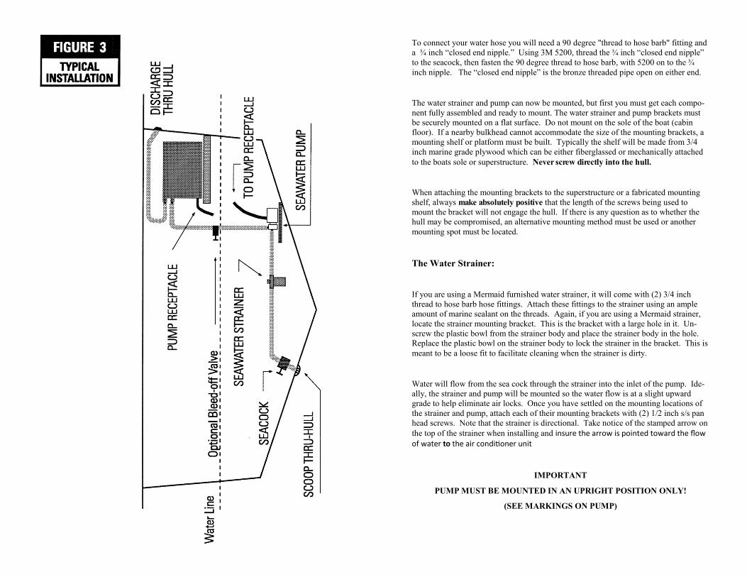
To connect your water hose you will need a 90 degree "thread to hose barb" fitting and
a ¾ inch “closed end nipple.” Using 3M 5200, thread the ¾ inch “closed end nipple”
to the seacock, then fasten the 90 degree thread to hose barb, with 5200 on to the ¾
inch nipple. The “closed end nipple” is the bronze threaded pipe open on either end.
The water strainer and pump can now be mounted, but first you must get each compo-
nent fully assembled and ready to mount. The water strainer and pump brackets must
be securely mounted on a flat surface. Do not mount on the sole of the boat (cabin
floor). If a nearby bulkhead cannot accommodate the size of the mounting brackets, a
mounting shelf or platform must be built. Typically the shelf will be made from 3/4
inch marine grade plywood which can be either fiberglassed or mechanically attached
to the boats sole or superstructure. Never screw directly into the hull.
When attaching the mounting brackets to the superstructure or a fabricated mounting
shelf, always make absolutely positive that the length of the screws being used to
mount the bracket will not engage the hull. If there is any question as to whether the
hull may be compromised, an alternative mounting method must be used or another
mounting spot must be located.
The Water Strainer:
If you are using a Mermaid furnished water strainer, it will come with (2) 3/4 inch
thread to hose barb hose fittings. Attach these fittings to the strainer using an ample
amount of marine sealant on the threads. Again, if you are using a Mermaid strainer,
locate the strainer mounting bracket. This is the bracket with a large hole in it. Un-
screw the plastic bowl from the strainer body and place the strainer body in the hole.
Replace the plastic bowl on the strainer body to lock the strainer in the bracket. This is
meant to be a loose fit to facilitate cleaning when the strainer is dirty.
Water will flow from the sea cock through the strainer into the inlet of the pump. Ide-
ally, the strainer and pump will be mounted so the water flow is at a slight upward
grade to help eliminate air locks. Once you have settled on the mounting locations of
the strainer and pump, attach each of their mounting brackets with (2) 1/2 inch s/s pan
head screws. Note that the strainer is directional. Take notice of the stamped arrow on
the top of the strainer when installing and insure the arrow is pointed toward the flow of water to the air conditioner unit
IMPORTANT
PUMP MUST BE MOUNTED IN AN UPRIGHT POSITION ONLY!
(SEE MARKINGS ON PUMP)
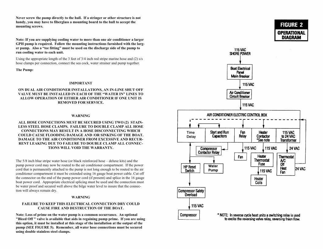
Never screw the pump directly to the hull. If a stringer or other structure is not
handy, you may have to fiberglass a mounting board to the hull to accept the
mounting screws.
Note: If you are supplying cooling water to more than one air conditioner a larger
GPH pump is required. Follow the mounting instructions furnished with the larg-
er pump. Also a “tee fitting” must be used on the discharge side of the pump to
run cooling water to each unit.
Using the appropriate length of the 3 feet of 3/4 inch red stripe marine hose and (2) s/s
hose clamps per connection, connect the sea cock, water strainer and pump together.
The Pump:
IMPORTANT
ON DUAL AIR CONDITIONER INSTALLATIONS, AN IN-LINE SHUT OFF
VALVE MUST BE INSTALLED IN EACH OF THE “WATER IN” LINES TO
ALLOW OPERATION OF EITHER AIR CONDITIONER IF ONE UNIT IS
REMOVED FOR SERVICE.
WARNING
ALL HOSE CONNECTIONS MUST BE SECURED USING TWO (2) STAIN-
LESS STEEL HOSE CLAMPS. FAILURE TO DOUBLE CLAMP ALL HOSE
CONNECTIONS MAY RESULT IN A HOSE DISCONNECTING WHICH
COULD CAUSE FLOODING DAMAGE AND /OR SINKING OF THE BOAT.
DAMAGE TO THE AIR CONDITIONER FROM EXCESSIVE AND RECUR-
RENT LEAKING DUE TO FAILURE TO DOUBLE CLAMP ALL CONNEC-
TIONS WILL VOID THE WARRANTY.
The 5/8 inch blue stripe water hose (or black reinforced hose – deluxe kits) and the
pump power cord may now be routed to the air conditioner compartment. If the power
cord that is permanently attached to the pump is not long enough to be routed to the air
conditioner compartment it must be extended using 16 gauge boat power cable. Cut off
the connector on the end of the pump power cord (if present) and splice in the 16 gauge
boat power cord. Appropriate electrical splicing must be used and the connection must
be water proof and secured well above the bilge water level to insure that the connec-
tion will always remain dry.
WARNING
FAILURE TO KEEP THIS ELECTRICAL CONNECTION DRY COULD
CAUSE FIRE AND DESTRUCTION OF THE BOAT.
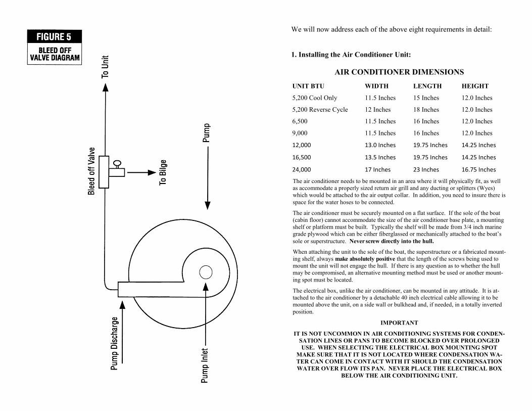
Note: Loss of prime on the water pump is a common occurrance. An optional
"Bleed Off " valve is available that aids in regaining pump prime. If you are using
this option, it must be installed at this stage of the installation at the output of the
pump (SEE FIGURE 5). Remember, all water hose connections must be secured
using double stainless steel clamps.
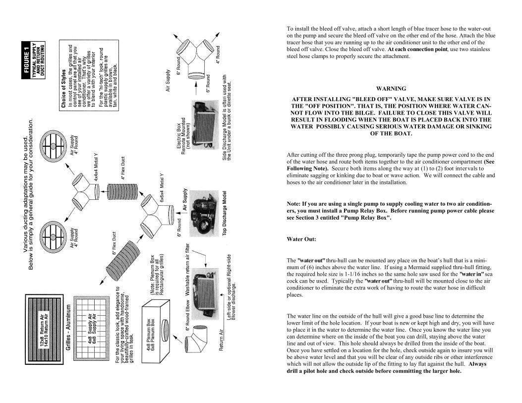
To install the bleed off valve, attach a short length of blue tracer hose to the water-out
on the pump and secure the bleed off valve on the other end of the hose. Attach the blue
tracer hose that you are running up to the air conditioner unit to the other end of the
bleed off valve. Close the bleed off valve. At each connection point, use two stainless
steel hose clamps to properly secure the attachment.
WARNING
AFTER INSTALLING "BLEED OFF" VALVE, MAKE SURE VALVE IS IN
THE "OFF POSITION". THAT IS, THE POSITION WHERE WATER CAN-
NOT FLOW INTO THE BILGE. FAILURE TO CLOSE THIS VALVE WILL
RESULT IN FLOODING WHEN THE BOAT IS PLACED BACK INTO THE
WATER POSSIBLY CAUSING SERIOUS WATER DAMAGE OR SINKING
OF THE BOAT.
After cutting off the three prong plug, temporarily tape the pump power cord to the end
of the water hose and route both items together to the air conditioner compartment (See
Following Note). Secure both items along the way at (1) to (2) foot intervals to
eliminate sagging or kinking due to boat or wave action. We will connect the cable and
hoses to the air conditioner later in the installation.
Note: If you are using a single pump to supply cooling water to two air condition-
ers, you must install a Pump Relay Box. Before running pump power cable please
see Section 3 entitled "Pump Relay Box".
Water Out:
The "water out" thru-hull can be mounted any place on the boat’s hull that is a mini-
mum of (6) inches above the water line. If using a Mermaid supplied thru-hull fitting,
the required hole size is 1-1/16 inches so the same hole saw used for the "water in" sea
cock can be used. Typically the "water out" thru-hull will be mounted close to the air
conditioner to eliminate the extra work of having to route the water hose in difficult
places.
The water line on the outside of the hull will give a good base line to determine the
lower limit of the hole location. If your boat is new or kept high and dry, you will have
to place it in the water to determine the water line. Once you know the water line you
can determine where on the inside of the boat you can drill, staying above the water
line and out of view. This hole should always be drilled from the inside of the boat.
Once you have settled on a location for the hole, check outside again to insure you will
be above water level and that you will be clear of any outside ribs or other interference
which will not allow the outside lip of the fitting to lay flat against the hull. Always
drill a pilot hole and check outside before committing the larger hole.

When installing the thru-hull fitting apply an ample amount of marine sealant to the
outside lip of the fitting and its mounting post. If possible, have someone hold the out-
side of the fitting to keep it from turning when you attach the retaining nut from the
inside. Be careful not to over tighten the nut. Use two (2) s/s hose clamps to attach the
hose to the thru-hull fitting. Route this hose into the air conditioner compartment where
it will eventually be connected to the condensing coil "water out" fitting.
3. Electrical Power:
Both the air conditioner and pump require 115 vac, 60 hertz power to operate. (220v
models are available) This power is obtained from the master 115 vac Circuit Breaker
Panel in the boat. Power is routed from this panel to the air conditioner. The air condi-
tioner will then supply power to the pump as required.
WARNING
BEFORE PROCEEDING FURTHER, CHECK TO INSURE THAT ALL 120
VAC POWER HAS BEEN DISCONNECTED FROM THE BOAT AND CIR-
CUIT BREAKER PANEL. FAILURE TO DO SO COULD CAUSE ELECTRI-
CAL SHOCK RESULTING IN SERIOUS INJURY OR DEATH
Using 12 gauge boat power cable, beginning on the inside of the Main Circuit Breaker
Panel, route the cable to the air conditioning compartment. Leave ample excess before
cutting to allow for positioning of the unit’s electric box at time of final hook up. Con-
nection of this cable to the air conditioner electrical box will be covered later.
At the circuit breaker panel locate a blank hole and install a 20 amp circuit breaker of
the same style as those breakers currently in the panel. Note that all of the breakers are
connected together on one side by either a buss bar or individual jumper wires. Con-
nect the new breaker in the same manner. Remove about 12 inches of the outer insula-
tion from the end of the boat cable to expose the inner wires. This cable contains (3)
inner insulated wires which are "BLACK", "WHITE" and "GREEN' in color. Using the
appropriate wire connectors, as those currently used in the panel, connect the wires as
follows: "BLACK" to the remaining terminal on the circuit breaker, "WHITE" to the
buss bar connecting all "WHITE" wires together and the "GREEN" to the buss bar con-
necting all "GREEN" wires together. The Main Circuit Breaker Panel can now be
closed up.
FOR 220V UNITS THAT HAVE A 4 WIRE SYSTEM WITH RED, BLACK,
WHITE, AND GREEN WIRES, THE FOLLOWING APPLIES:
BLACK GOES TO BLACK (HOT)
RED GOES TO WHITE (NEUTRAL)
GREEN GOES TO GROUND
WHITE GETS CUT OFF AND NOT USED
MERMAID PRESSURE SETTINGS
AND FREON QUANTITIES WATER TEMPERATURE
66
66
67
68
69
70
71
72
73
74
75
76
77
78
79
80
81
82
83
84
85
86
87
88
89
90
91
92
93
94
HIGH SIDE PRESSURES
183
186
189
192
195
198
201
204
207
210
213
216
219
222
225
228
231
235
239
242
245
249
253
256
261
266
268
270
273
277
FREON QUANTITIES
**UNITS MANUFAC-
TURED PRIOR TO THE
YEAR 2010 ARE
CHARGED WITH R-
22**
(R-22 FREON)
M5 - 5.5 OUNCES
M6 - 6.0 OUNCES
M9 - 6.5 OUNCES
M12 - 12.3 OUNCES
M16 - 13.5 OUNCES
M24 - 14.5 OUNCES
**UNITS MANUFAC-
TURED IN 2010 OR AF-
TER ARE CHARGED
WITH NU-22**
(NU-22 FREON)
M5 - 8OUNCES
M6 - 9 OUNCES
M9 - 10 OUNCES
M12 - 10 OUNCES
M16 - 11 OUNCES
M24 - 1 LB 1.5 OUNCES
YOU MAY SAVE A FEW DOLLARS, AND MORE IMPORTANTLY, TIME, BY
TAKING THE UNIT TO FEDEX OR A FEDEX SHIPPER YOURSELF. INSURE
THE UNIT!!! WE CANNOT BE RESPONSIBLE FOR DAMAGE IN SHIPPING.
WE ALWAYS, ALWAYS, ALWAYS SHIP OUR UNITS WITH FULL INSURANCE.
WE GENERALLY REPAIR 90% OF UNITS WITHIN 24 HOURS OF ARRIVAL AT
OUR FACTORY, AND ALL UNITS ARE REPAIRED WITHIN 48 HOURS OF AR-
RIVAL. FOR THE 5 YEAR WARRANTY PERIOD ALL REPAIR COSTS, RE-
PLACEMENT PARTS, LABOR, ETC. ARE AT OUR EXPENSE AS WE INSURE
THE UNIT IS REFURBISHED TO 100% OF ORIGINAL FACTORY SPECIFICA-
TIONS. WE WILL SHIP THE UNIT BACK TO YOU AT OUR COST VIA FEDEX
GROUND SERVICE, AS WE STATED IN OUR WARRANTY.
AIR FREIGHT OPTIONS ARE AVAILABLE, BUT THE DIFFERENCE BETWEEN
FEDEX GROUND AND THESE SERVICES ARE AT YOUR COST.
REPAIR ISSUES – UNITS BEYOND WARRANTY/OUT OF WARRANTY….SAME
PROCEDURE AS ABOVE TO GET THE UNIT TO US. REMEMBER, INSURE
THE UNIT. WE CANNOT BE RESPONSIBLE FOR DAMAGE TO A UNIT IN
TRANSIT. WE WILL EVALUATE THE UNIT AND PROVIDE A REPAIR ESTI-
MATE FOR YOU. UPON YOUR APPROVAL, WE WILL REFURBISH THE UNIT
TO AT LEAST, ORIGINAL FACTORY SPECIFICATIONS. FROM TIME TO
TIME, WE CHANGE VENDORS, PARTS, ETC. TO CONTINUOSLY IMPROVE
THE RELIABILITY OF OUR PRODUCT. WHEN YOUR UNIT IS RETURNED,
COSMETIC ASPECTS OF YOUR UNIT MAY BE DIFFERENT, BUT WE GUAR-
ANTEE THAT IT MEETS OR EXCEEDS ORIGINAL FACTORY SPECIFICA-
TIONS.
California Proposition 65 warning: California Proposition 65, The Safe Drinking
Water and Toxic Enforcement Act of 1996, requires that all products sold within the
state of California must provide a warning if the product contains any of the current list
of chemicals known to cause cancer, birth defects or other reproductive harm. Our units
use solder to braze piping connections within the unit, and our optional installation kits
include a bronze foot scoop and a bronze sea cock. Solder and bronze contain traces of
lead, a chemical on the list of toxic substances. It is believed that the amount of expo-
sure to lead is so minimal that it poses no significant risk. However in the spirit of the
disclosure act, be advised that there are trace quantities of lead used in the manufacture
of this product. The company has not undertaken the cost to demonstrate and prove that
an exposure can occur at a level to pose no significant risk.
4. Air Ducting and Splitting:
Regardless of the btu size of the air conditioner, at least one vent must be within 4 to 5
feet of the unit. Insure though, that the airflow is not directed back towards the return
air grill. In the case of the 16,500 btu unit, the largest grill is required to be the closest
grill. Improper ducting accounts for the majority of marine air conditioning problems.
Though there are exceptions to the rule, the following rule of thumb applies to the num-
ber and size of the supply air grills required for each btu size air conditioner:
5,200 btu unit: (2) four inch grills.
6,500 btu unit: (2) to (3) four inch grills.
9,000 btu unit: (3) to (4) four inch grills
12,500 btu unit: (Cool only) (3) or more four or six inch grills.
(With electric heat) Same as cool only.
(With reverse cycle heat) (1) six inch grill and (2) or more four inch grills.
16,500 btu unit: (1) six inch grill and (2) or more four inch grills
24,000 btu unit: Minimum of three 6 inch vents/grills
When it comes to ducting, a general rule is that more grills are always better. Any time
more than one supply air grill is used, an air splitter is required. Air splitters come in a
variety of sizes and styles. Splitters may be mounted directly on the unit output air
collar, or placed in line a short distance from the unit where space restrictions preclude
mounting the splitter on the unit. Additional air splitters may be used at various inter-
vals along the duct routing to distribute air to multiple cabins. Wye’s are always prefer-
able to Tee’s. We do not use Tee’s for air splitters. Refer to FIGURE 1 for a typical
ducting scheme.
When surveying the boat for your air conditioner mounting spot, you must also decide
what size supply air grills will be used and where they will be mounted. The size of the
grill will dictate the size of the ducting. It is also important that you decide upon using
insulated or non-insulated air duct before beginning. Generally the ducting will be 4
inch, 5 inch or 6 inch diameter non-insulated duct. If you decide on insulated duct, add
2 inches to the outside diameter of the non-insulted duct. Typically power boats will
use non-insulated duct and sail boats insulated. Except for passing through a hot engine
room, the only benefit in using insulated duct is preventing condensation forming on
the exterior of the duct (sweating) which could cause water staining on fabrics. Be-
cause sail boats generally sit lower in the water and have less glass than power boats,
they tend to produce more duct condensation than the power boat, however, space re-
straints may not allow the total use of insulated duct and you may need to use a combi-
nation of the two duct types. Some situations will require the use of non-insulated duct,
but will require insulating the duct after the installation with a insulation wrap. All duct
runs should be as short and straight as possible. Every 90 degree turn in a duct run
reduces performance by about 14%. Ducting should be tied to a per manent struc-
ture every foot or two to eliminate sagging. Using tie wraps, insure ducting is appropri-
ately fastened to each supply air grill.
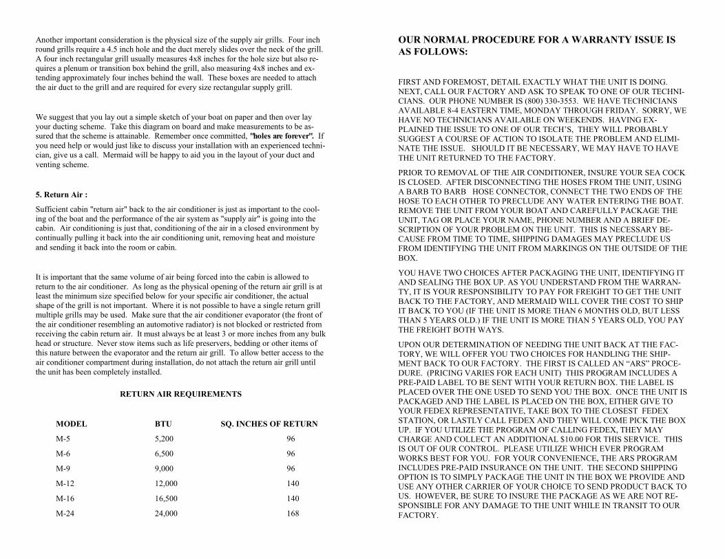
Another important consideration is the physical size of the supply air grills. Four inch
round grills require a 4.5 inch hole and the duct merely slides over the neck of the grill.
A four inch rectangular grill usually measures 4x8 inches for the hole size but also re-
quires a plenum or transition box behind the grill, also measuring 4x8 inches and ex-
tending approximately four inches behind the wall. These boxes are needed to attach
the air duct to the grill and are required for every size rectangular supply grill.
We suggest that you lay out a simple sketch of your boat on paper and then over lay
your ducting scheme. Take this diagram on board and make measurements to be as-
sured that the scheme is attainable. Remember once committed, "holes are forever". If
you need help or would just like to discuss your installation with an experienced techni-
cian, give us a call. Mermaid will be happy to aid you in the layout of your duct and
venting scheme.
5. Return Air :
Sufficient cabin "return air" back to the air conditioner is just as important to the cool-
ing of the boat and the performance of the air system as "supply air" is going into the
cabin. Air conditioning is just that, conditioning of the air in a closed environment by
continually pulling it back into the air conditioning unit, removing heat and moisture
and sending it back into the room or cabin.
It is important that the same volume of air being forced into the cabin is allowed to
return to the air conditioner. As long as the physical opening of the return air grill is at
least the minimum size specified below for your specific air conditioner, the actual
shape of the grill is not important. Where it is not possible to have a single return grill
multiple grills may be used. Make sure that the air conditioner evaporator (the front of
the air conditioner resembling an automotive radiator) is not blocked or restricted from
receiving the cabin return air. It must always be at least 3 or more inches from any bulk
head or structure. Never stow items such as life preservers, bedding or other items of
this nature between the evaporator and the return air grill. To allow better access to the
air conditioner compartment during installation, do not attach the return air grill until
the unit has been completely installed.
RETURN AIR REQUIREMENTS
MODEL BTU SQ. INCHES OF RETURN
M-5 5,200 96
M-6 6,500 96
M-9 9,000 96
M-12 12,000 140
M-16 16,500 140
M-24 24,000 168
OUR NORMAL PROCEDURE FOR A WARRANTY ISSUE IS
AS FOLLOWS:
FIRST AND FOREMOST, DETAIL EXACTLY WHAT THE UNIT IS DOING.
NEXT, CALL OUR FACTORY AND ASK TO SPEAK TO ONE OF OUR TECHNI-
CIANS. OUR PHONE NUMBER IS (800) 330-3553. WE HAVE TECHNICIANS
AVAILABLE 8-4 EASTERN TIME, MONDAY THROUGH FRIDAY. SORRY, WE
HAVE NO TECHNICIANS AVAILABLE ON WEEKENDS. HAVING EX-
PLAINED THE ISSUE TO ONE OF OUR TECH’S, THEY WILL PROBABLY
SUGGEST A COURSE OF ACTION TO ISOLATE THE PROBLEM AND ELIMI-
NATE THE ISSUE. SHOULD IT BE NECESSARY, WE MAY HAVE TO HAVE
THE UNIT RETURNED TO THE FACTORY.
PRIOR TO REMOVAL OF THE AIR CONDITIONER, INSURE YOUR SEA COCK
IS CLOSED. AFTER DISCONNECTING THE HOSES FROM THE UNIT, USING
A BARB TO BARB HOSE CONNECTOR, CONNECT THE TWO ENDS OF THE
HOSE TO EACH OTHER TO PRECLUDE ANY WATER ENTERING THE BOAT.
REMOVE THE UNIT FROM YOUR BOAT AND CAREFULLY PACKAGE THE
UNIT, TAG OR PLACE YOUR NAME, PHONE NUMBER AND A BRIEF DE-
SCRIPTION OF YOUR PROBLEM ON THE UNIT. THIS IS NECESSARY BE-
CAUSE FROM TIME TO TIME, SHIPPING DAMAGES MAY PRECLUDE US
FROM IDENTIFYING THE UNIT FROM MARKINGS ON THE OUTSIDE OF THE
BOX.
YOU HAVE TWO CHOICES AFTER PACKAGING THE UNIT, IDENTIFYING IT
AND SEALING THE BOX UP. AS YOU UNDERSTAND FROM THE WARRAN-
TY, IT IS YOUR RESPONSIBILITY TO PAY FOR FREIGHT TO GET THE UNIT
BACK TO THE FACTORY, AND MERMAID WILL COVER THE COST TO SHIP
IT BACK TO YOU (IF THE UNIT IS MORE THAN 6 MONTHS OLD, BUT LESS
THAN 5 YEARS OLD.) IF THE UNIT IS MORE THAN 5 YEARS OLD, YOU PAY
THE FREIGHT BOTH WAYS.
UPON OUR DETERMINATION OF NEEDING THE UNIT BACK AT THE FAC-
TORY, WE WILL OFFER YOU TWO CHOICES FOR HANDLING THE SHIP-
MENT BACK TO OUR FACTORY. THE FIRST IS CALLED AN “ARS” PROCE-
DURE. (PRICING VARIES FOR EACH UNIT) THIS PROGRAM INCLUDES A
PRE-PAID LABEL TO BE SENT WITH YOUR RETURN BOX. THE LABEL IS
PLACED OVER THE ONE USED TO SEND YOU THE BOX. ONCE THE UNIT IS
PACKAGED AND THE LABEL IS PLACED ON THE BOX, EITHER GIVE TO
YOUR FEDEX REPRESENTATIVE, TAKE BOX TO THE CLOSEST FEDEX
STATION, OR LASTLY CALL FEDEX AND THEY WILL COME PICK THE BOX
UP. IF YOU UTILIZE THE PROGRAM OF CALLING FEDEX, THEY MAY
CHARGE AND COLLECT AN ADDITIONAL $10.00 FOR THIS SERVICE. THIS
IS OUT OF OUR CONTROL. PLEASE UTILIZE WHICH EVER PROGRAM
WORKS BEST FOR YOU. FOR YOUR CONVENIENCE, THE ARS PROGRAM
INCLUDES PRE-PAID INSURANCE ON THE UNIT. THE SECOND SHIPPING
OPTION IS TO SIMPLY PACKAGE THE UNIT IN THE BOX WE PROVIDE AND
USE ANY OTHER CARRIER OF YOUR CHOICE TO SEND PRODUCT BACK TO
US. HOWEVER, BE SURE TO INSURE THE PACKAGE AS WE ARE NOT RE-
SPONSIBLE FOR ANY DAMAGE TO THE UNIT WHILE IN TRANSIT TO OUR
FACTORY.
8. High Pressure Switch Activates In Cooling Mode:
a) Only a lack of cooling water will activate the high pressure switch when the air con-
ditioner is operated in the COOL mode. See paragraph 4 (No Water Out) above.
9. High Pressure Switch Activates In Heating Mode:
a) When the high pressure switch activates in the HEAT mode, the evaporator is not
being properly relieved of heat. This is due to air flow restrictions. Remove the re-
striction.
Dirty air filter.
Blocked return air.
Return air grill smaller than specified physical size.
Closed or insufficient number of supply air grills.
Duct runs too long, too many turns or kinks creating a heat back up on the
evaporator.
10. No Heat - Electric Heat Unit - Fan Runs:
Note: Remember that on electric heat models the pump nor the compressor will
run. Only the fan and the heater coil are activated.
a) Check for loose or disconnected wires in the electrical box. Before opening electrical
box remove all 115 (220) vac power from boat. See above WARNINGS regarding 115
(220) vac power.
b) If wiring is deemed good, problem will either be a faulty thermal safety fuse or a
faulty heater coil. Usually the thermal fuse is the problem. To replace either item, re-
move the metal cover from around the evaporator by removing two screws on each side
and two bracket screws on the top of the evaporator. The evaporator cover will pull
straight up exposing the coil and fuse. Both items can be checked with a continuity
checker. Replace the faulty item and reposition the cover and replace the retaining
screws.
11. No Heat - Reverse Cycle Unit - Compressor And Fan Run:
a) Reversing valve sticking. Tap lightly with handle of screw driver.
b) Reversing valve solenoid loose or wire off. Tighten nut on solenoid and/or secure
wire.
c) Loose wire or faulty reversing valve relay in electrical box. Remove all power to
boat before opening electrical box. See 115 (220) vac WARNING under paragraph 1i)
above. Repair wire and/or r eplace reversing valve relay.
d) Faulty compressor. Replace compressor. Requires professional service.
6. High Pressure Switch Access:
All Mermaid marine air conditioners utilize a manual High Pressure safety switch. This
switch monitors the system’s high pressure any time the compressor is running. If a
condition occurs that causes the system high pressure to rise to a level that could dam-
age the compressor, the switch will activate and remove power from the compressor
and pump. Once activated, this switch must be manually reset. The switch is a green
cylindrical object with a red button . You must provide enough space to reach
your hand into the compartment or cut an access hole in the cabinet above or
alongside the switch to reset it after activation.
When the air conditioner is operating in the cooling mode only the lack of sufficient
cooling water can cause high pressure. In reverse cycle heat pump units operating in
the heating mode, high pressure can only be created by over heating of the evaporator
which is generally caused by insufficient return air or restricted supply air. The trouble
shooting guide covers these and other problems.
7. Condensation Removal:
Depending on the btu rating of your unit and the actual run time, the air conditioner will
remove from one to five gallons of water (condensation) from the air in a 24 hour peri-
od. This water collects in the condensation pan to be drained out. Most boat owners
will drain this water into the bilge for removal overboard by the existing bilge pumps.
When running your condensation hose remember that condensation flows only by grav-
ity and the hose must never rise up any where along the way or condensation will back-
up into the pan and overflow. This will not sink your boat, but it can get the surround-
ing area very wet. In many boats it is not possible to drain to the bilge, and the conden-
sation must be removed by other means, such as a “Mermaid Condensator Kit”. Please
contact your Mermaid dealer or the factory for other options to remove condensation.
8. Mounting The STANDARD Thermostat: (Programmable + Non-
Programmable)
NOTE: SEE SEPARATE FX-1 THERMOSTAT OWNERS AND OPERATIONS
MANUAL FOR INSTALLATION AND INSTRUCTIONS PERTAINING TO
THIS PRODUCT. THIS MANUAL WILL BE INCLUDED UPON THE PUR-
CHASE OF THIS PRODUCT
The 24v thermostats come with a 20 foot power cable. One end of the cable attaches to
the BLACK terminal board on the side of the air conditioner electrical box. The other
end is wired into the black teminal board inside the thermostat itself.
The thermostat may be mounted on any flat wall surface with space behind the wall to
run the thermostat power cable out of view and still reach the air conditioner electrical
box. Ideally, the thermostat will be about 2/3 up on an interior wall, out of direct sun
light and not directly in front of a "supply air" vent, nor next to a hatch. It is important
that the thermostat be located where it is sensing “true” cabin temperature rather than a
“dead” spot, or getting incorrect readings from sunlight or sampling air near a constant-
ly opening/closing hatch thereby reading “outside” air rather than inside air.
Once you have selected the spot, remove the face of the thermostat from the back panel
and install by following these instructions:
1. Depress the thumb tab on the bottom of the thermostat and carefully pull the two
pieces apart.
2. 2.Lift the thermostat up and off the subbase.
3. Drill a 1/4 inch hole in the wall and feed the cable through. With the cable behind
the wall, the thermostat back plate can be pressed flat to the wall. Now mark the
mounting hole spots on the wall. Only two 1/2 s/s screws are needed to secure the
thermostat. Predrill the holes before screwing to the wall. (Exact vertical mount-
ing is necessary only for appearance).
4. Route the thermostat power cable, out of view, back to the air conditioner com-
partment. Secure the cable at appropriate spots along the way to prevent sagging
or looping so it will not be inadvertently snagged by stowed equipment.
5. To connect your gray thermostat wire to the thermostat AND the black electrical
box, follow these procedures:
A. On both ends of the gray wire, cut away the gray insulation being careful
not to cut into the RED, GREEN, WHITE, AND BLACK wires.
B. Install the four fork terminals (provided) by stripping back ¼” of each of
the colored wires and crimping the terminals to the wires. Ensure with your
crimp that you have a solid grasp of the wire, not insulation.
C. The four fork terminal connection will be connected to the black terminal
block on the upper side of the black electrical box for the air conditioning
unit. Follow the R = RED, G = GREEN, W = WHITE, B = BLACK color
code for the connections at the electrical box.
D. For connections at the thermostat, install (if already not done so) the RED
“jumper” wire (provided) between the “RH” and “RC” terminals inside the
subbase of the thermostat.
E. Carefully insert the other end of the previously ¼” stripped gray wire into
the appropriate locations. Follow the chart below for guidance.
Red wire = “RH/RC” connection on thermostat – either “RH” or “RC” lead is
acceptable as the red jumper wire (provided) connects these terminals togeth-
er. This is the unit’s 24 volts from the transformer when heating or cooling is
called for.
Green wire = “G” connection on thermostat. This is the fan operation wire.
White wire = “W” connection on thermostat. This wire is for heat – if your
system is a heating/cooling unit.
Black wire = “Y” connection on thermostat. This wire is for the cooling
mode. Do not connect the black wire to “B” on the sub base.
5. Evaporator Freezing:
a) Supply air vents closed or insufficient number of vents. Open and/or add additional
vents.
b) Fan not running or intermittent. See paragraph 3 above.
c) Return air blocked. Clean air filter and/or remove any blockage.
d) Thermostat set too low and is not allowing unit to cycle and remove icing. Set ther-
mostat at a higher setting.
e.) Thermostat improperly located in a position not giving “true” cabin temperature.
Examples would be in a sunny spot near glass, or near the hatch. Relocate thermostat.
f) Low freon due to leak. Unit will require professional service.
6. Condensation Pan Overflows:
a) Drain pan nipple on pan clogged. Clean nipple.
b) Drain hose clogged, misaligned or kinked. Fix and/or clear hose.
c) Air conditioner not properly elevated to drain water to drain pan nipple. Check unit
mounting to insure water will flow to nipple.
7. Circuit Breaker Will Not Stay On:
a) Shorted wire. See the WARNING under paragraph 1i above r egarding electr ical
service in and outside of the electrical box and at the circuit breaker. Check for loose or
disconnected wires. Reconnect or replace as necessary.
b) Pump internally shorted. Remove pump power from electrical box and start the unit.
If circuit does not trip, replace pump.
c) Check circuit breaker for proper operation. If faulty, replace circuit breaker.
d) Compressor shorted internally. Compressor must be replaced professionally.
2. Standard 24v Thermostat In COOL Position - Fan Runs - Compressor Does
Not:
a) Place thermostat in the OFF position. Locate the HIGH PRESSURE switch mounted
on the top of the air conditioner unit. Check if the red button is active or extended. If
the pin is extended, push it in. This switch shuts power off to the compressor when
cooling water is insufficient to make the required heat exchange as described in Theory
Of Operation above. Check water pump for prime and motor operation, check raw
water strainer for clogging and hoses for kinks. Fix water problem and turn thermostat
back on.
b) If water pump is operational and HIGH PRESSURE switch has not activated, per-
form thermostat jumper test described in paragraph 1h) above. If unit operates, replace
thermostat batteries and/or thermostat.
3. Compressor Runs - Fan Does Not:
a) Place thermostat in the OFF position. Use a shorting wire as described in paragraph
1h above, except this time short the "RED" wire to the "GREEN" wire. If fan comes
on, thermostat is faulty.
b) If fan does not come on when jumper is applied, it is most likely a faulty fan relay
inside the electrical box or an external fan capacitor. Replace the fan relay or capacitor
with the recommended from the factory. Before opening the electrical box, all 115
(220) power must be removed from the boat. See the above Note and WARNING un-
der paragraph 1i) regarding opening the electrical box.
4. No Water Out:
a) Put thermostat in OFF position.
b) Check that sea cock is open. If closed, open and prime pump.
c) Check raw water strainer. If dirty, clean and prime pump.
d) Check that pump is running. If pump is faulty, replace and prime.
e) Check for any obstructions in the intake or strainer/water lines. Periodic growth of
barnacles or accumulated debris may block the water intakes.
f) If this is a new installation, check to make sure that pump, water strainer and sea cock
are all below sea level. Pump will not prime if any of these parts are above sea level.
Also ensure the caps have been removed from the water (condensing) coil.
9. Putting it all together:
At this point the unit can be placed back into its compartment, and all the power, water
hoses and ducting should be available and ready to connect:
IMPORTANT
DO NOT CUT ANY EXCESS WATER HOSE , WIRE OR DUCTING BEFORE
DETERMINING THAT ALL REQUIREMENTS CAN BE MET WHEN UNIT IS
SECURED.
Position the air conditioner unit so "water in" and "water out" hoses can be attached
without kinking. Now check the air splitter and ducting for fit. Make sure that all duct-
ing bends are as slight as possible to keep air restriction to a minimum. Once you are
satisfied with the compromises you have made between the water and the air connec-
tions, locate a place for the electric box. Remember this box may be mounted in any
attitude, but must never get wet. Now, before cutting any excess hose, etc., check
to see that all four air conditioner mounting screws can be installed without making
contact with the hull.
Note: Enclosed in the kit is a "S" shaped flat metal bracket with a hole drilled in
one end of the "S". This is the "hold down bracket" for the fourth mounting
screw. This bracket will slip over the side of the evaporator condensation pan and
the fourth mounting screw will be used to secure it. Because this bracket can be
placed anywhere on the pan, you have a good deal of latitude in tight situations for
installing the screw.
The air conditioner unit may now be secured. For vibration reduction, ensure the in-
cluded foam insulation mounting pad is under the air conditioning unit. Do not secure
the electric box at this time.
Next, cut the water hoses to fit and attach each hose with two s/s hose clamps. Make
sure that each hose is placed on the proper end of the condensing coil as marked ("water
-in/water-out"). BE SURE TO REMOVE THE PLASTIC CAPS ON THE WA-
TER-IN/WATER-OUT ENDS OF THE CONDENSING COIL. THESE WERE
INSTALLED FOR SHIPPING PURPOSES ONLY.
Connect the clear 3/8 inch hose to the nipple on the condensation pan. This hose gener-
ally fits snugly without a hose clamp.
Using the full length of the electric box cable or unplugging the cable, bring the box out
to where it is more convenient for you to work with in making all the required connec-
tions. (SEE WARNING BELOW)
WARNING
MAKE SURE THAT ALL AC POWER TO THE BOAT HAS BEEN DISCON-
NECTED. FAILURE TO REMOVE ALL BOAT AC POWER COULD RESULT
IN ELECTRICAL SHOCK CAUSING SERIOUS INJURY OR DEATH.
Determine which power cable is from the pump (16 gauge cable) and strip the outside
insulation back about six inches. Then strip each of the three individual wires back
about 1/4 inch. Facing the WHITE terminal block on the side of the electric box, locate
the connection labeled "PUMP". Using the appropriate size flat blade screw driver,
open the connections marked "WHITE" and "BLACK" and slide the "BLACK" and
"WHITE" wires into the open connector slots for each color. Make sure that no bare
wire is exposed outside the connector slot and tighten the screw. Pull each wire to in-
sure it is tightly connected. Using an appropriate size electrical ring connector, attach
the "GREEN" wire to the "GROUND" post located on the mounting bracket.
WARNING
HAVING ANY BARE WIRE EXPOSED OUTSIDE THE WHITE TERMINAL
BLOCK COULD CREATE ELECTRICAL SHOCK CAUSING SERIOUS INJU-
RY OR DEATH.
Next, locate the 115 (or 220) vac power cable from the Circuit Breaker Panel (12 gauge
cable) and connect this cable to the electric box WHITE terminal block by inserting the
wires into the connector slots marked "POWER". To do this, follow the same proce-
dure as with the pump connections. (SEE ABOVE WARNING ON EXPOSED BARE
WIRE CONNECTIONS)
Locate the BLACK terminal strip on the outside of the electrical box (just above the
power terminal block) and attach the thermostat power cable. This terminal strip is
color coded for easy determination of which wire is attached to which connection
("RED" to "R", "GREEN" to "G" etc.). Any excess cable may be neatly coiled next to
the box or cut off and shortened to fit. If excess is cut off, do not make connections
with bare wires, install new connectors on each wire.
IMPORTANT
MAKE SURE THAT YOU SECURE ALL LOOSE WIRING AND HOSES WITH
APPROPRIATE SIZE NYLON CLIPS OR CABLE TIES TO MAKE SURE
THAT BOAT OR WAVE ACTION WILL NOT CAUSE STRESS OR KINKING.
NOTE:
THE FX-1 THERMOSTAT CONTROL BOX IS PRE-WIRED FOR YOU. ON-
LY ELECTRICAL (110V / 220V) AND PUMP CONNECTIONS ARE REQUR-
IED ON THE CONTROL BOX INSTALLATION FOR THIS PRODUCT
WARNING
ALWAYS USE EXTREME CARE WHEN CHECKING 115 VAC POWER.
CONTACT WITH 115 VAC POWER CAN CAUSE SERIOUS INJURY OR
DEATH.
f) If no power is coming from control box and confirmed power coming into control
box, then you must open control box by removing the three cut screws on each side of
the box and pull the lid/cover off the box. Once opened you will see a 30 amp in line
blade fuse. An extra replacement fuse is taped to the inside cover which you can use to
replace the blown fuse. This is to protect boards or components from lightning or other
power surges. If you need any extra fuses, contact the factory or you may purchase at
any automobile supply place. Replace the cover and turn the power back on.
g) If power is not present, check 115 (220) power leads on unit electrical box WHITE
terminal block for polarity, tightness and for signs of discoloration. If power is still not
present, check the air conditioner circuit breaker in the Main Circuit Breaker Panel for
loose connections (SEE ABOVE WARNING).
h) If 115 (220) vac power was present at the WHITE terminal block, using your AC
voltmeter, check for 24 vac on the "RED" wire attached to the BLACK terminal board
located directly above the WHITE terminal block on the side of the electrical box. You
should get a reading by placing one voltmeter lead on the "RED" wire and the other
lead on any other remaining lead along the black terminal board – WHITE, BLACK,
OR GREEN.
i) If 24 vac is present and all of the above checks and procedures are positive, most
likely the thermostat is faulty or a wire has loosened inside the electrical box. To check
the thermostat, take a 5 or 6 inch piece of insulated wire, strip the insulation back about
1/8 inch on each end and use it to short the "RED" wire to the "BLACK" wire on the
BLACK terminal board. If the unit immediately comes on, the thermostat is faulty and
needs replacing. If the unit does not operate, the problem is in the electrical box.
j) If 24 vac was not present in step g) above, most likely the transformer inside the
electrical box is faulty or a wire has loosened inside the box.
Note: Once a problem has been isolated to the internal portion of the electrical
box, the box must now be opened. Before preceding further, you must disconnect
all 115 (220) vac electrical power to the boat. (SEE WARNING BELOW)
WARNING
IF ALL 115 VAC POWER IS NOT DISCONNECTED FROM THE BOAT YOU
MAY INCUR ELECTRICAL SHOCK WHICH CAN CAUSE SERIOUS INJU-
RY OR DEATH.
k) After you have removed all 115 (220) vac electrical power, the electrical box cover
may be removed by removing the three retaining screws on each side of the box. Once
the screws are removed the cover will slide off the box.
l) Closely check the box for loose or disconnected wires. If all wiring is tight and in
place, replace the transformer. A new transformer may be purchased from your nearest
Mermaid dealer, refrigeration supply store or direct from the Mermaid factory.
c) Electric Heat Units: When the HEAT-OFF-COOL switch is placed in the HEAT
position and the SET temperature is set above cabin ambient temperature, the thermo-
stat will activate the heat contactor relay and the fan relay. When the heat contactor
relay is activated, 115 vac will be applied to the heater coils through a heater thermal
fuse. The heater coils will begin to heat up. At this same instant, the fan relay is acti-
vated, applying 115 vac to the fan which will began to run. The main contactor relay is
not activated in the electric heat mode and the compressor and pump will not run.
Not available in 220v.
d) Heat Pump Units: When the HEAT-OFF-COOL switch is placed in the HEAT posi-
tion and the SET temperature is set above cabin ambient temperature, the thermostat
will activate the fan relay and the reversing valve relay. The reversing valve relay will
in turn apply 24 vac activation power to the main contactor relay and the reversing
valve solenoid. The fan relay and main contactor relay will activate as described in
paragraph b) above. When the reversing valve solenoid is activated, a metal bar inter-
nal to the reversing valve will be physically moved directing the system freon to flow
through a different port causing it, in effect, to flow in the opposite direction. This will
cause the evaporator to heat up as described in paragraph 2 above.
4. Cooling Water:
a) Cooling water enters the boat through the foot scoop under the boat, up into the boat
through the sea cock, into the raw water strainer through the strainer and into the "water
in" por t on the water pump. The water pump is controlled by the electr ical box
and will be turned on and off with the air conditioner compressor. When the pump is
operational, it forces the cooling water through the "double fluted" air conditioner con-
densing coil "inner chamber," cooling the system freon which is flowing through the
condensing coil "outer chamber". After passing through the condensing coil, the cool-
ing water, now warm from the heat exchange in the condensing coil, is passed over-
board through the "water out" thru-hull fitting (See FIGURE 3).
B. TROUBLE SHOOTING:
1. Standard 24v Thermostat In COOL Position - No Operation:
a) Make sure that Thermostat delay period has expired. Delay may be as long as 5
minutes.
b) Check SET temperature to make sure temperature is set below cabin temperature.
c) Once you are satisfied that the delay period has expired, check that both boat main
circuit breaker and air conditioner circuit breakers are in the ON position.
d) If both breakers are in the ON position, check to see if boat power source is present. If power source is present, turn on another boat 115 vac accessory to make sure main breaker is operational.
e) If main breaker is operational, using an AC voltmeter, check for 115 vac power at the unit electrical box.
RANGE OF VOLTAGE:
(MINIMUM - 95 ) (MAXIMUM - 125)
Now connect the air splitter and air ducting. You may use appropriate size cable ties or
a high grade ducting tape. If the air splitter is attached directly to the unit air collar, we
recommend that you secure it with one or two 1/2 inch s/s screws along with duct tape
or foil tape.
Now, attach the return air grill and your installation is completed.
B. SYSTEM OPERATION:
Note: If the boat has not been placed back in the water, do so now. The air condi-
tioner requires proper cooling water to operate.
1. Priming The Pump:
a) Because marine air conditioner pumps are not self priming, generally, the pump may
need priming each time the boat is removed from the water and then placed back into
the water. Priming may also be required when the water strainer is cleaned or when the
boat has returned to the dock after being used. Normally, once primed at the dock, the
pump will retain its prime until used or taken in and out of the water as mentioned
above.
b) To prime the pump, open the sea cock and view the water flow through the clear red
stripe hose. If the water flows into the input of the pump with no air bubbles in the
strainer or hose, the pump is primed. However, if air bubbles are present you must
loosen the hose clamps on the pump discharge hose (blue stripe or black reinforced)
and momentarily remove the hose. Water will immediately flow from the pump break-
ing the air lock. Quickly replace the hose and retighten the hose clamps. The pump is
now primed. If you have installed the optional "Bleed Off" valve, it is usually not nec-
essary to remove the discharge hose from the pump. Open the "Bleed Off" valve until
water flow is observed and then close the valve. (Ideally this water should be directed
to the bilge or a container that can be later discharged overboard).
WARNING
AS STATED EARLIER, FAILURE TO CLOSE THE "BLEED OFF" VALVE
WILL RESULT IN FLOODING AND POSSIBLE SINKING OF THE BOAT.
Note: If water does not flow from the pump when the discharge hose is removed or
from the "Bleed Off" valve when opened, the pump is not below the water line of
the boat and must be remounted.
2. Power:
a) With the air conditioner circuit breaker in the "OFF" position connect the dock power cord back to the boat.
b) Place the main circuit breaker and the air conditioner circuit breaker in their "ON" positions.
3. Water Out:
a) Once the air conditioner starts, immediately go out on deck and check that water is
coming out of the "water out" thru-hull. Once all of the latent air is forced from the
hoses a steady stream should be present with enough force that the water stream clears
the side of the boat hull.
b) If the water flow is not present or weak, the pump was not properly primed. Shut the
air conditioner off and prime the pump as described above. (You may also attempt to
prime via the bleed off valve ONLY while the air conditioner is running – allowing for
the pump to function). If the air conditioner is allowed to run without water for more
than a minute, the High Pressure switch will activate and disengage power from the
compressor. Once the water problem is corrected, you will need to reset the High Pres-
sure switch by pushing the extended RED button in with your finger. The High Pres-
sure switch is located on the top of the 6,500 BTU, 9,000 BTU, 12,000 BTU,
16,500BTU, or 24,000BTU air conditioner and is on the upper side of the 5,200 BTU
unit. It is green in color with a bright RED push tab.
4. Checking Out The System:
a) Air Flow: Once the air conditioner is running and water flow is present, check each
supply air vent to make sure it is open and cooling air is present. If air flow is not pre-
sent, check ducting for good air tight connections and that kinking or sagging of the
duct has not occurred.
b) Water Connections: Check each water connection beginning at the sea cock, then the
water strainer, pump, the air conditioner and the "water out" thru-hull. No water leaks
should be present. Also, at this time, it is always good to check the hose clamps for
tightness in case one may have been overlooked during installation.
c) Condensation: By now the unit should be producing condensation. Check to make
sure that condensation is flowing freely into the condensation hose. If the unit has not
produced sufficient condensation to check the flow, pour water into the condensation
pan to see that in fact it is flowing freely.
d) The Air Conditioner Unit: The unit should be free of vibration noises and the sides
of the evaporator should be sweating and cool all the way up. If vibration noise is pre-
sent, adjust the unit mounting screws. If this does not correct the noise, use a socket
wrench with an extender or a large phillips head screwdriver (or 5/16 nut runner if ap-
plicable) and tighten down the compressor mounting bolts until the vibration noise
stops. In some situations, although very rare, it may lessen the sound vibration to actu-
ally loosen the compressor bolts a very, very small amount. In some boats where a
mounting shelf was installed, sound will travel through the board to the side walls and a
"speaker effect" will take place. The included mounting pad should eliminate a gener-
ous portion of any known / heard vibration.
*As of 2015 there may be a 3 min. delay for M16 Tecumseh compressors to regulate*
2. Heating Options:
Mermaid offers two optional types of heating technologies for their units. One option
is "electric heat". This option employs electrical heating coils placed in the path of
cabin return air. Return air is heated as it passes over the electrical coils and is then
forced back into the cabin. The electric heat option is available only on the M-6, M-9
and M-12 Models. The second heat option is a "heat pump". In this option the system
freon is forced to flow through the unit evaporator in a reverse direction heating the
evaporator. Cabin return air is pulled through the evaporator, heating the air as it pass-
es through, and then forces it back into the cabin. This is the same principal used in
many home and pool heating devices and is also referred to as "reverse cycle" heat.
The heat pump option is available with all the Mermaid models.
3. Electrical:
a) All Mermaid air conditioner models are available in either 115 vac or 220 vac con-
figurations. Shore power is applied to the air conditioner from the boat’s main circuit
breaker through a dedicated air conditioner circuit breaker to the air conditioner elec-
trical box. This power is distributed to various components inside the electrical box
including a 115/220 vac to 24 vac reduction transformer. The thermostat utilizes the
24 volts to activate the appropriate relays inside the electrical box which, when ener-
gized, apply 115 or 220 vac power to the blower, compressor and water pump.
Through a time-delay device inside the electrical box, the power is provided to the
pump and blower immediately, followed by the power to the compressor approximate-
ly ½ to 1 second later. This device is advantageous for those “limited power supply”
situations by lowering the initial starting surge. The blower may be operated inde-
pendently of the compressor and water pump if only circulating air and not refrigerat-
ed air is desired. This is accomplished by simply placing the FAN switch in the FAN
ON position. (Mermaid’s FX-1 Controls utilize 110v or 220v operation and time de-
lays are automatic in the programming on the circuit board.)
b) When the HEAT-OFF-COOL switch is placed in the COOL position and the SET
temperature is set below cabin ambient temperature, the thermostat will activate both
the fan and main contactor relays in the electrical box. When the main contactor relay
is activated, 115 vac will be applied to the water pump and fan relay powering the
blower, followed by a ½ to 1 second delay providing power to the start and run capaci-
tors as well as the high pressure switch. If the high pressure switch is closed, power
will pass through the switch to the compressor safety switch to the "compressor" mo-
tor windings. 115 vac power is also applied to the compressor motor "run" and "start"
windings from the start and run capacitors. The compressor will now begin to run
along with the previously running fan and pump.
SECTION 6
THEORY OF OPERATION AND
TROUBLE SHOOTING
CLEAN AIR ACT AMENDMENTS OF 1990 [TITLE VI - SECTION 608(C-1)]
"Effective July 1, 1992, it shall be unlawful for any person, in the course of maintain-
ing, servicing, repairing, or disposing of an appliance or industrial process refrigeration,
to knowingly vent or otherwise knowingly release or dispose of any Class I* or Class
II** substance used as a refrigerant in such appliance (or industrial process refrigera-
tion) in a manner which permits such substance to enter the environment. De minimis
releases associated with good faith attempts to recapture and recycle or safely dispose
of any such substances shall not be subject to the prohibition set forth in the proceeding
sentence." *Class I substances include CFC-12
**Class II substances include HCFC-22
Mermaid air conditioners manufactured prior to the year 2010 is charged with R-22.
Mermaid air conditioners manufactured in 2010 or later are charged with NU-22. CFC-
12 (R12) has never been used in Mermaid air conditioners, it is unlawful for any techni-
cian who is not EPA certified as at least a Type1.
A. THEORY of OPERATION:
1. General:
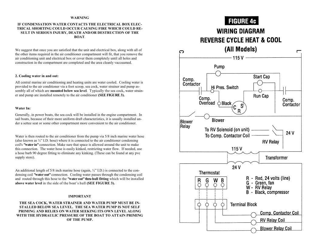
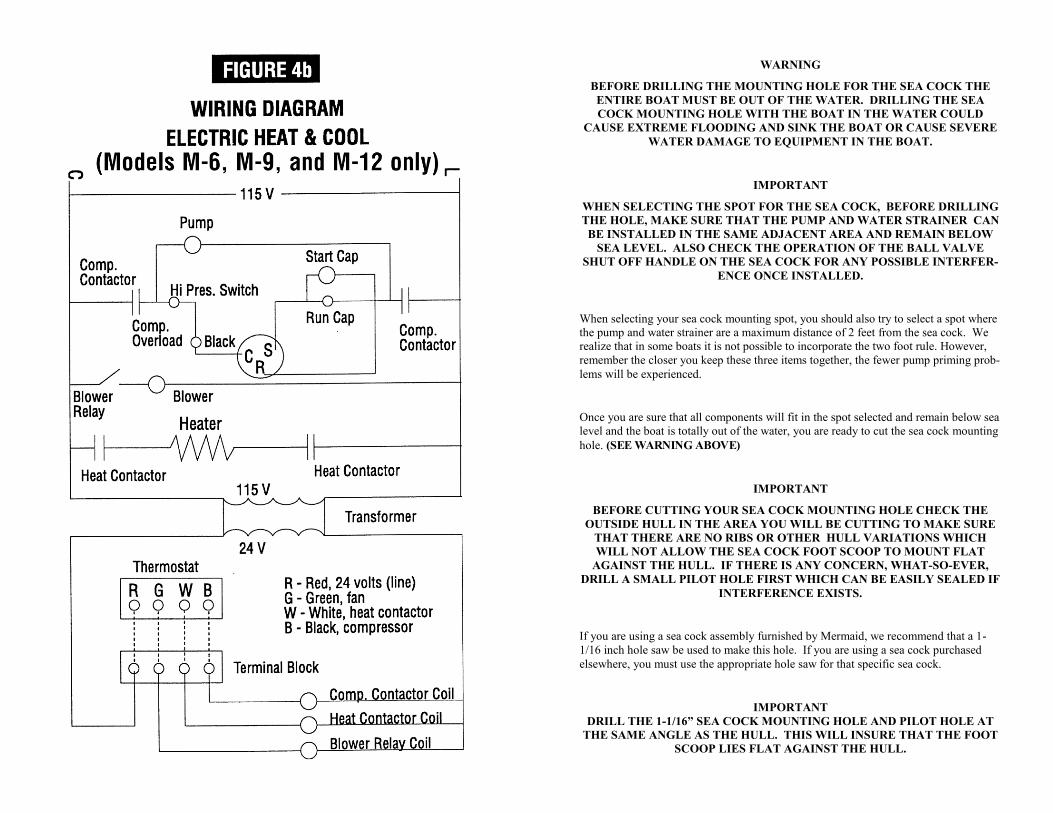
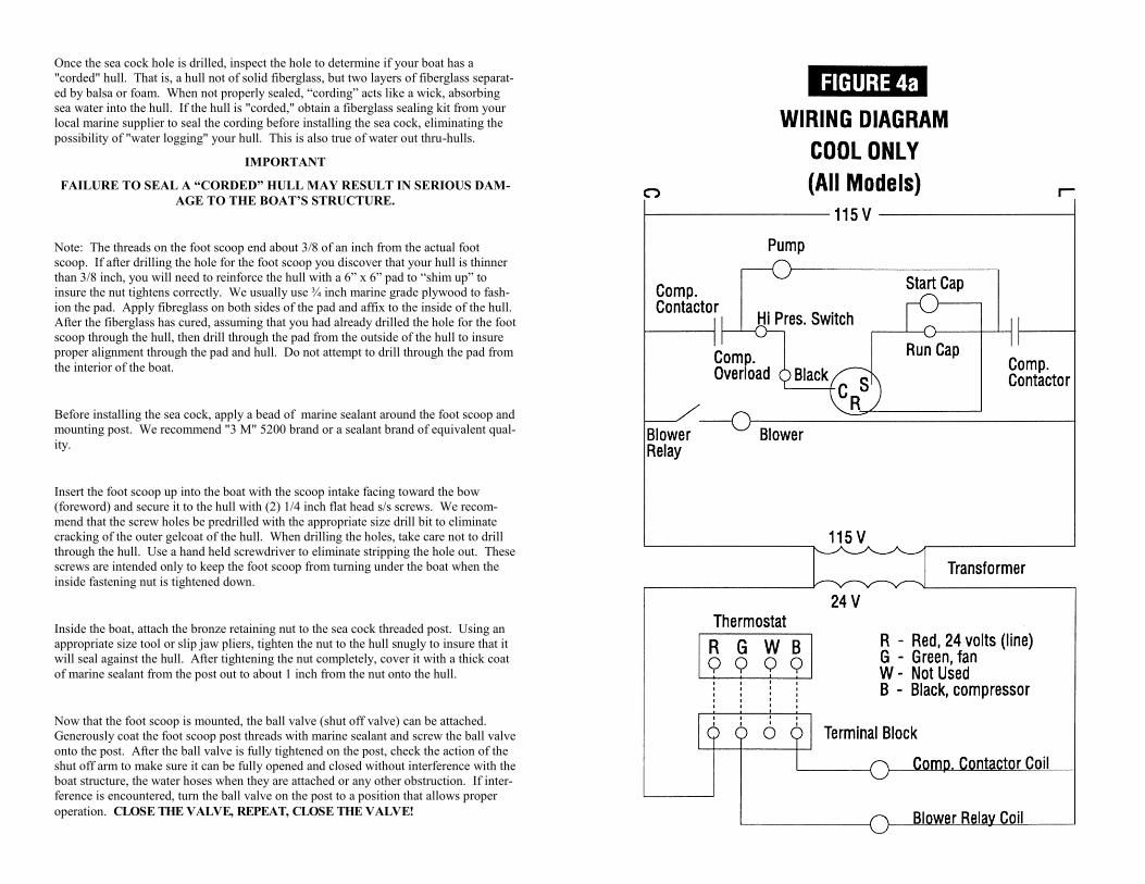
Note: It is helpful to refer to the Operational Block Diagram, FIGURE 2, and the
Model Wiring Diagrams, FIGURES 4a through 4c, as you read this Theory of
Operation.
All Mermaid "cool only" air conditioning units are controlled and function exactly the
same, regardless of the btu capacity of the unit. Units equipped with a "heat option" are
controlled in the same manner as "cool only" units, but may employ completely differ-
ent concepts for producing heat. The digital thermostat is the master control of the
system and dictates the operational mode of the air conditioning unit through an electri-
cal control box. Though the thermostat has many operational modes, such as operation-
al programming, time of day, etc., all you need to do to operate the basic functions of
cool and heat is to put the HEAT-OFF-COOL switch in the applicable position and
depress the UP or DOWN ARROW to set the desired temperature.
SECTION 3
A. INTRODUCTION
In August of the year 2004 we discovered an unacceptable amount of failures with the
previously provided thermostat. After careful testing, we have replaced that model with
the one now being described. We hope to hear of your success.
Standard Features Include:
Battery back-up with two AA batteries
100% solid state circuitry
Built-in short cycle protection during normal operation (up to 5 minutes)
Auto or manual fan operation
Constant hold feature allows continuous override
Temporary temperature override
Selectable Fahrenheit or Celsius temperature display (refer to included manual)
Large liquid crystal display (LCD) – easy to read
Available 12 or 24 hour clock (refer to included manual)
Here is another copy of the items listed on page 15 and 16 regarding mounting the
thermostat. Should you not need this section again, proceed to section B for SET-
TING THE CURRENT DAY AND TIME
The thermostat comes with a 20 foot power cable. One end of the cable attaches to the
BLACK terminal board on the side of the air conditioner electrical box. The other end
is wired into the black terminal board inside the thermostat itself. (Directions listed
below.)
The thermostat may be mounted on any flat wall surface with space behind the wall to run the power cable out of view and still reach the air conditioner electrical box. Ideal-ly, the thermostat will be about 2/3 up on an interior wall, out of direct sun light and not directly in front of a "supply air" vent, nor next to a hatch. It is important that the thermostat be located where it is sensing “true” cabin temperature rather than a “dead” spot, or getting incorrect readings from sunlight or sampling air near a con-stantly opening/closing hatch thereby reading “outside” air rather than inside air.
NOTE: THE MERMAID FLUSH MOUNT CONTROLLER (FX-1) AND NON-
PROGRAMMABLE 24V THERMOSTAT MANUALS ARE PROVIDED WITH
EACH UNIT
OPERATION & PROGRAMMING MANUAL FOR
MERMAIDS’ STANDARD DIGITAL
24V THEROMSTAT
Once you have selected the spot, remove the face of the thermostat from the back panel
and install by following these instructions:
1. Depress the thumb tab on the bottom of the thermostat and carefully pull the two
pieces apart.
2. 2.Lift the thermostat up and off the subbase.
3. Drill a 1/4 inch hole in the wall and feed the cable through. With the cable behind
the wall, the thermostat back plate can be pressed flat to the wall. Now mark the
mounting hole spots on the wall. Only two 1/2 s/s screws are needed to secure the
thermostat. Predrill the holes before screwing to the wall. (Exact vertical mount-
ing is necessary only for appearance).
4. Route the thermostat power cable, out of view, back to the air conditioner com-
partment. Secure the cable at appropriate spots along the way to prevent sagging
or looping so it will not be inadvertently snagged by stowed equipment.
5. To connect your gray thermostat wire to the thermostat AND the black electrical
box, follow these procedures:
A. On both ends of the gray wire, cut away the gray insulation being careful
not to cut into the RED, GREEN, WHITE, AND BLACK wires.
B. Install the four fork terminals (provided) by stripping back ¼” of each of
the colored wires and crimping the terminals to the wires. Ensure with your
crimp that you have a solid grasp of the wire, not insulation.
C. The four fork terminal connection will be connected to the black terminal
block on the upper side of the black electrical box for the air conditioning
unit. Follow the R = RED, G = GREEN, W = WHITE, B = BLACK color
code for the connections at the electrical box.
D. For connections at the thermostat, install (if already not done so) the RED
“jumper” wire (provided) between the “RH” and “RC” terminals inside the
subbase of the thermostat.
E. Carefully insert the other end of the previously ¼” stripped gray wire into
the appropriate locations. Follow the chart below for guidance.
Red wire = “RH/RC” connection on thermostat – either “RH” or “RC” lead is
acceptable as the red jumper wire (provided) connects these terminals togeth-
er. This is the unit’s 24 volts from the transformer when heating or cooling is
called for.
Green wire = “G” connection on thermostat. This is the fan operation wire.
White wire = “W” connection on thermostat. This wire is for heat – if your
system is a heating/cooling unit.
Black wire = “Y” connection on thermostat. This wire is for the cooling
mode. Do not connect the black wire to “B” on the sub base.
B. WINTERIZATION:
1. Air Conditioning Unit and Water Pump:
a) If your boat is in the water, you must first close the "water in" sea cock before pro-
ceeding with winterization.
WARNING
FAILURE TO CLOSE SEA COCK BEFORE REMOVING WATER HOSES
MAY RESULT IN FLOODING CAUSING SIGNIFICANT WATER DAMAGE
OR SINKING OF THE BOAT.
b) The condensing coil, the coil that connects to cooling "water in" and cooling "water
out", must be clear of any standing or trapped water . The best way to clear this
coil is to remove the "water in" hose from the coil and place a short piece of the same
diameter hose on the condensing coil. Blow through the short hose until no water
comes out of the "water out" thru-hull fitting on the outside of the boat. A compressed
air source would be ideal, should you have access to one.
c) Before replacing the condensing coil "water in" hose, go to where the pump is locat-
ed and remove the "water in" hose to the water pump. This is the hose between the
pump and the water strainer. Now return to the air unit and blow through the "water
in" hose forcing any tr apped water back and through the pump. Again, a com-
pressed air source would be ideal, should you have access to one. This will clear the
hose and the pump. Replace both hoses to their original connections.
d) If you have any doubt about not clearing the condensing coil, you can add a legally
acceptable standard antifreeze or alcohol to the coil. Certain locales prohibit the use of
automotive antifreeze. Should you be using alcohol, insure you do not allow alcohol to
be in the water strainer. Clear plastic water strainer cups will cloud with alcohol.
e) Winterization is now completed. If the boat is to remain in the water, do not reopen
the sea cock until you are r eady to again use the air conditioning unit when freez-
ing is no longer a threat.
WARNING
IF THE SEA COCK IS REOPENED WITH THE BOAT IN THE WATER AND
FREEZING OCCURS, WATER HOSES MAY RUPTURE AND FLOODING
MAY OCCUR CAUSING SIGNIFICANT DAMAGE OR SINKING OF THE
BOAT
SECTION 5
MAINTENANCE AND WINTERIZATION
A. MAINTENANCE:
1. Water System:
a) After the first 30 days of operation, check all water connections for leaks and all hose
clamps to insure that none have become loose. It is always a good policy to make peri-
odic checks of all water connections and to close the "water in" sea cock whenever you
leave the boat for extended periods of time.
b) Your water strainer will require cleaning on a regular basis. The time between clean-
ings will be dependent on the condition of the water your boat resides in, the amount of
time your air unit operates, and the physical size of the strainer you have installed. After
you have had your unit for a few months you will develop a feel for how often you
should clean the strainer basket.
2. Air System:
a) There is little maintenance required for the air system. The main item is the air filter
located on the front of the air unit evaporator. This filter will require cleaning on a regu-
lar basis. As with the water strainer, the time between cleanings will be dependent on
operating time and environment. For instances, if you have a pet, the time between
cleanings will be shorter due to the pet hair that will be pulled onto the filter. The filter
is easily cleaned by washing it in plain tap water. Never operate the air unit for extend-
ed periods of time without the air filter in place. The debris that would normally be
collected by the filter will become lodged in the evaporator coil cooling fins and will
gradually reduce the efficiency and performance of your air conditioner to a point that it
will require professional acid bath cleaning.
b) When cleaning the filter, also wipe the unit off with a dry cloth to eliminate dust build
up. Check that the air ducting has not sagged or loosened around the air collar or air
vents.
3. Electrical System:
a) Unless you have some reason to suspect an electrical problem, there is no mainte-
nance required for the electrical system; However, as always, it is prudent to do cursory
checks on all equipment on your boat as you perform your general maintenance on vari-
ous equipment and systems throughout the year.
A. SETTING THE CURRENT DAY AND TIME
Open the drop down door on the front of the thermostat. Rotate the dial to the SET
DAY/TIME position. You should see the display read 12:00 with a flag pointing to a
day of the week flashing. When you are finished setting the day and time, rotate the
dial to RUN to return to normal operation or to another position to continue program-
ming.
B. NORMAL OPERATION
For immediate comfort, when the system switch is moved to the COOL or HEAT posi-
tion, simply press the TEMP Down or Up key until your air conditioner turns on to the
desired set temperature. It is advisable depress the HOLD button as this point. This
will maintain the previously set temperature within one degree until another
change is made to the TEMP setting. The ther mostat will alternate diplays be-
tween the current set time and the room temperature. It also displays the day of the
week and the currently active control program that is controlling the termperature:
MORN, DAY, EVE, or NIGHT.
Setting the FAN switch to AUTO automatically runs the system’s fan during heating
and cooling modes. Setting the FAN switch to ON runs your system’s fan continuously
even without heating or cooling.
C. PROGRAMMING THE THERMOSTAT
You can change any of the preset times and/or temperatures to suit your schedules for
the weekday and weekend programs. Each day is divided into four periods: Morning,
Day, Evening, and Night. Each period is programmed for HEAT and for COOL.
1. Select HEAT to program the thermostat for controlling the HEAT cycle.
2. Select COOL to program the thermostat for controlling the COOL cycle.
3. Rotate the dial to SET WEEKDAY PROGRAM. To program the WEEKEND,
rotate the dial to SET WEEKEND PROGRAM.
D. TEMPERATURE OVERRIDE AND TEMPERATURE HOLD
These features let you change the current Set Temperature without changing the pro-
grams stored in your thermostat’s memory.
TEMPORARY TEMPERATURE OVERRIDE:
Press UP/DOWN to change the current temperature setting. The OVERRIDE indicator
appears on the display. The OVERRIDE feature will be automatically canceled at the
start of the next program period. To cancel OVERRIDE prior to next program period
press UP/DOWN until original set temperature appears. OVERRIDE indicator will
disappear from display.
VACATION TEMPERATURE HOLD:
Press HOLD. Adjust temperature as desired with UP/DOWN. Temperature setting
will not change even after next program period begins. To clear, press HOLD again.
SECTION 4
PUMP RELAY BOX
FOR USE WITH MERMAID STANDARD 24V CONTROLS
The Mermaid Flush Mount Controller (FX-1) Thermostat requires a different
pump relay box. Mermaid’s Flush Mount Controller (FX-1) utilizes a 110V or
220V circuit. Contact the Mermaid factory for details. The instructions for the FX-
1 Thermostat Relay Box will be included upon the purchase of this product.
A. INTRODUCTION:
1. When two (or more) air conditioners are to be cooled using a single water pump a
relay switching box must be used to interface the air conditioners to the pump. Only
one air conditioner can be allowed to apply power to the pump at any give time to pre-
clude a doubling of power on the pump. The relay switching box will recognize the
first air unit providing power to the pump. Whenever the pump is running both units
will receive water even if the second (or more) unit is not in operation. When the addi-
tional air unit(s) becomes operational the relay switching box will isolate this unit from
the pump so double power is not applied; However, if the first air unit reaches tempera-
ture and shuts down, the relay switching box will automatically turn control of the
pump operation over to the additional unit(s) allowing normal operation to continue.
The additional air unit(s) will maintain control of the pump until it reaches temperature
and cycles off even if the first unit cycles back on while the additional unit is operating.
2. A separate 5 amp circuit breaker will be required to be installed in the Main Circuit
Breaker Panel to provide power to the Pump Relay Box.
3. On the outside of the Pump Relay Box are two (or more) terminal blocks. One is
marked PUMP and POWER. This is where the incoming voltage from the breaker panel
and the outgoing power to the pump will be connected. The other terminal block(s) are
marked B W B W. This is where the control voltage coming in from each air condition-
er will be connected.
B. INSTALLATION:
1. Before proceeding further put the air conditioner(s) circuit breakers in their "OFF"
positions and disconnect all AC power from the boat.
WARNING
FAILURE TO DISABLE ALL AC POWER TO THE BOAT COULD RESULT
IN ELECTRICAL SHOCK CAUSING SERIOUS INJURY OR DEATH.
WARNING
THE PUMP RELAY BOX MUST BE IN A DRY NON-EXPLOSIVE ENVIRON-
MENT. EXPOSURE TO EXPLOSIVE MATERIALS OR VAPORS MAY
CAUSE EXPLOSION RESULTING IN SERIOUS INJURY, DEATH, OR DE-
STRUCTION OF THE BOAT. EXPOSURE TO WATER COULD CAUSE
ELECTRICAL SHORTING RESULTING IN FIRE AND DESTRUCTION OF
THE BOAT.
2. Install a 5 amp circuit breaker in the Main Circuit Breaker Panel using 16 gauge boat
power cable. Route this cable to the Pump Relay Box which must be mounted in a dry
non-explosive environment adjacent to the pump. Before cutting the cable leave a suf-
ficient amount to properly locate the box when installation is completed. Follow the
same installation procedure for this circuit breaker as with the 20 amp air conditioning
unit circuit breaker described in the Owner’s and Operations Guide. At the pump relay
box, connect this cable to the terminal block marked POWER, white wire to the termi-
nal marked WHITE and the black wire to the terminal marked BLACK. Using a ring
terminal, attach the green wire to the post marked GROUND located on the side of the
relay box.
3. Connect the pump to the terminal block marked PUMP, white wire to the terminal
marked WHITE and the black wire to the terminal marked BLACK. Using a ring termi-
nal, attach the green wire to the post marked GROUND located on the side of the relay
box.
4. On the first air conditioner, locate the terminal block marked PUMP. Run a 16 gauge
boat cable from here to the terminal block marked B W on the pump relay box. Strip all
wires back ¼” .Using ring terminals, connect the green on both ends to GROUND. On
the air conditioner end, connect the white to the PUMP terminal marked WHITE and
the black wire to the PUMP terminal marked BLACK.
5. Repeat this same operation for any additional air conditioning units that are to use
this same water pump.
6. All wiring is completed. Secure the Pump Relay Box bracket to a convenient string-
er or bulkhead and installation is complete.