notes lecture7 gsm
DESCRIPTION
a brief explanation about GSMTRANSCRIPT
TI - 1011 1
Cellular Mobile Communication Systems
Lecture 7
Engr. Shahryar SaleemAssistant Professor
Department of Telecom EngineeringUniversity of Engineering and Technology
TaxilaTI - 1011
TI - 1011 2
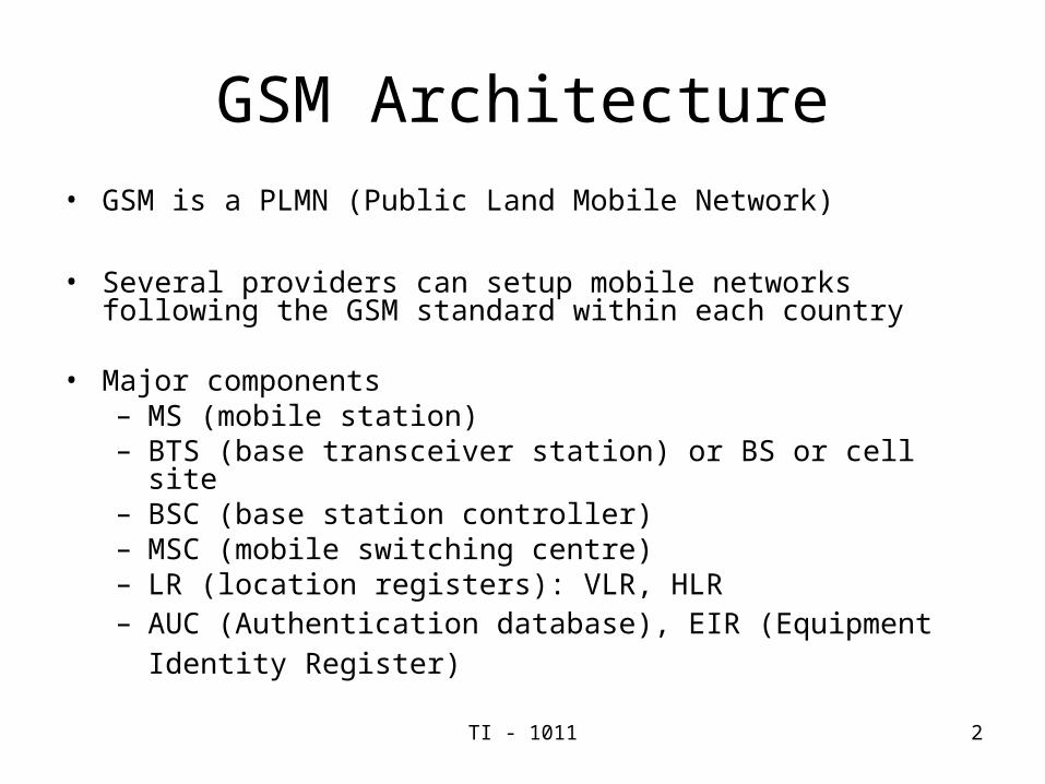
GSM Architecture• GSM is a PLMN (Public Land Mobile Network)
• Several providers can setup mobile networks following the GSM standard within each country
• Major components
– MS (mobile station)– BTS (base transceiver station) or BS or cell site– BSC (base station controller)– MSC (mobile switching centre)– LR (location registers): VLR, HLR– AUC (Authentication database), EIR (Equipment Identity
Register)
TI - 1011 3
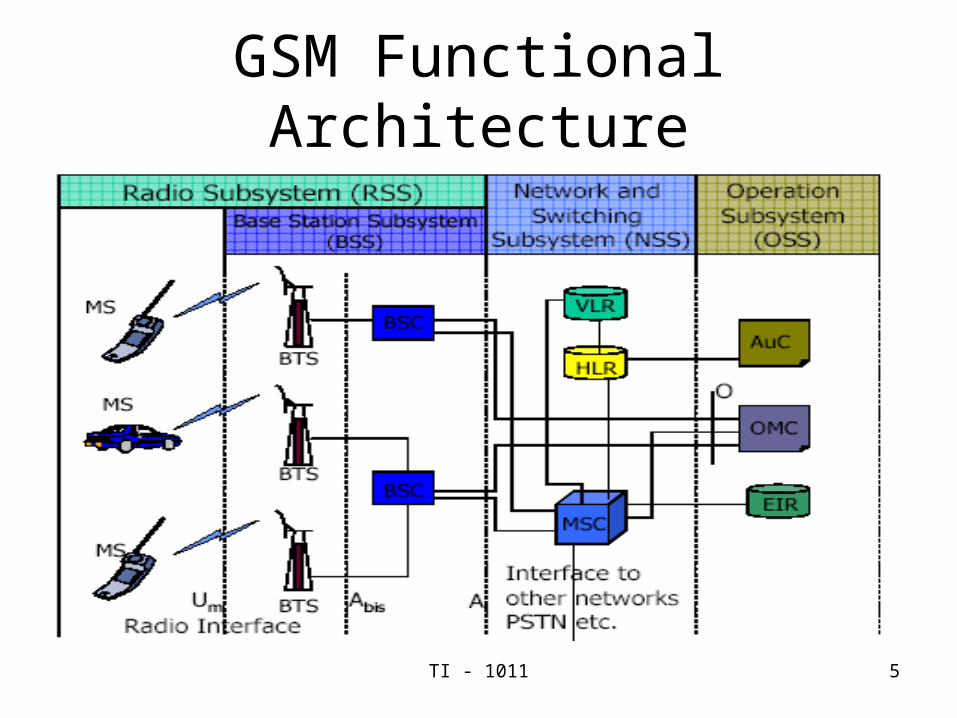
GSM Architecture• Subsystems
– RSS (radio subsystem): covers all radio aspects
– NSS (network and switching subsystem): call forwarding, handoff, switching, location tracking, etc.
– OSS (operation support subsystem): management of the network
• Standardized interfacesAllows provider to mix and match vendor equipment
TI - 1011 4
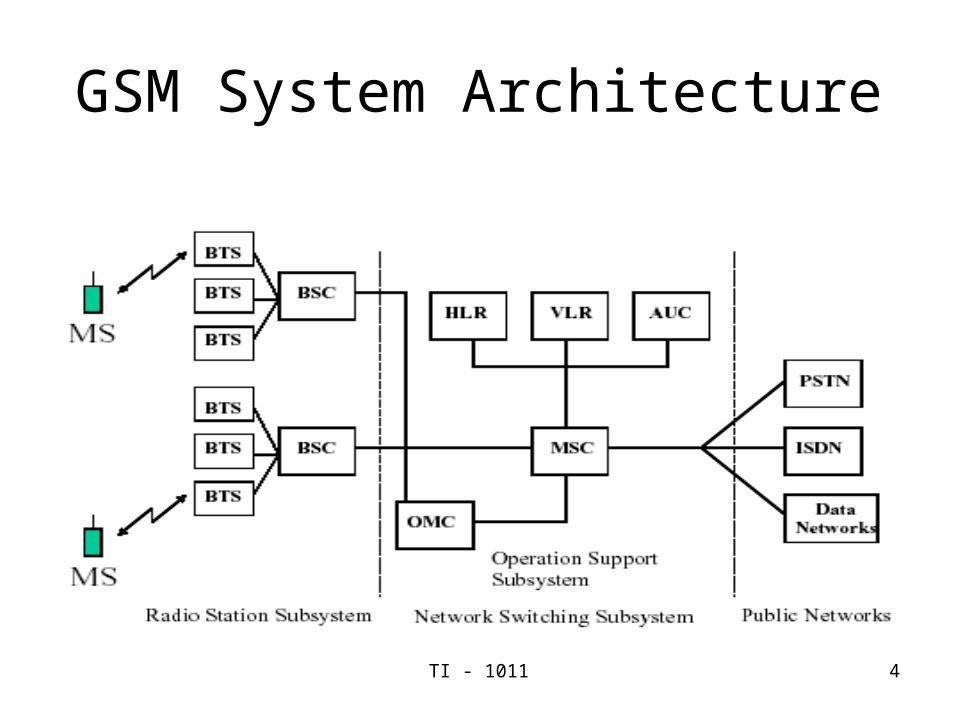
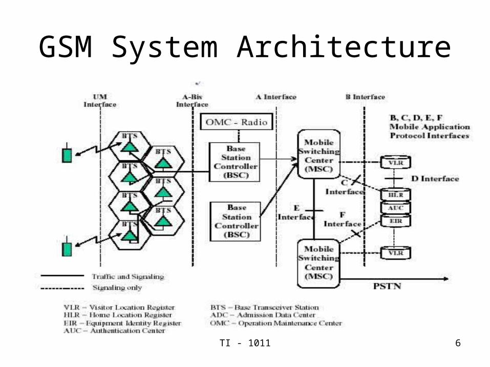
GSM System Architecture
TI - 1011 5
GSM Functional Architecture
TI - 1011 6
GSM System Architecture
TI - 1011 7
Mobile Station
• An MS consists of the physical equipment used by a user to access a PLMN
• A mobile station (MS) comprises several functional groups MT (Mobile Terminal)
End-point of the radio interface (Um) TA (Terminal Adaptor)
Terminal adaptation, hides radio specific characteristics TE (Terminal Equipment)
Peripheral device of the MS, offers services to a user SIM (Subscriber Identity Module)
Stores user parameters such as subscriber number, authentication Key, PIN etc
• An Ms has a number of identities– IMEI, IMSI, TMSI etc
TI - 1011 8
Radio Station Subsystem• Components• MS (Mobile Station)
• BSS (Base Station Subsystem)– Physical equipment to provide radio coverage to cells– BSS consists of two functional units BTS and BSC
• BTS (Base Transceiver Station): Antenna + digital radio equipment
• BSC (Base Station Controller): Controlling several transceivers, map radio channels (Um) onto terrestrial channels A
TI - 1011 9
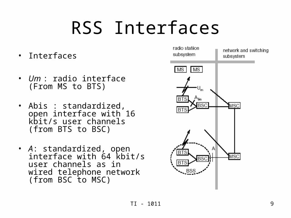
RSS Interfaces• Interfaces
• Um : radio interface (From MS to BTS)
• Abis : standardized, open interface with 16 kbit/s user channels (from BTS to BSC)
• A: standardized, open interface with 64 kbit/s user channels as in wired telephone network (from BSC to MSC)
TI - 1011 10
System Architecture Network and Switching Subsystems
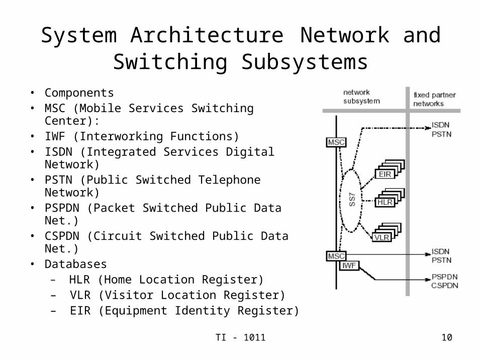
• Components• MSC (Mobile Services Switching Center):• IWF (Interworking Functions)• ISDN (Integrated Services Digital Network)• PSTN (Public Switched Telephone
Network)• PSPDN (Packet Switched Public Data
Net.)• CSPDN (Circuit Switched Public Data Net.)• Databases
– HLR (Home Location Register)– VLR (Visitor Location Register)– EIR (Equipment Identity Register)
TI - 1011 11
NSS
• NSS includes the main switching function of GSM• Databases for users• Mobility management• Most important role is to manage the communication
between GSM and other network users Components• Mobile Switching Center (MSC)
– Performs the necessary switching functions – Monitors the mobility of its users– Manages Handoff functions– Involved in inter-working functions to communicate with
other networks such as PSTN and ISDN etc.– The inter-working functions depends on the types of
networks and the types of services to be performed
TI - 1011 12
NSS Components
• Home Locator Register (HLR)– Functional unit for management of mobile subscriber– HLR stores two types of information: Subscriber information and
part of mobile information (to allow incoming calls to be routed to the MSC for a particular MS)
• HLR contains– Subscriber ID (IMSI and MSISDN)– Current Subscriber VLR (Current Location)– Supplementary Services – Authentication KEY and AUC functionality– MSRN
TI - 1011 13
NSS Components
• Visitor Locator Register (VLR)– The VLR is linked to one or more MSCs– Functional unit which dynamically stores subscriber information
when the subscriber is located in the area covered by the VLR
TI - 1011 14
VLR
• When a roaming MS enters an MSC area, the MSC infoems the associated VLR about the MS
• The MS goes through a registration process which includes– The VLR recognizes that the MS is from another PLMN
– If roaming is allowed, the VLR finds the MS’s HLR in home PLMN
– VLR constructs a Global Title (GT) from the IMSI to allow signalling form the VLR to the MS’s HLR via PSTN/ISDN networks
– VLR generates a Mobile Subscriber Roaming Number (MSRN) that is used to route incoming calls to the MS
– The MSRN is sent to the MS’s HLR
The information in the VLR includes MSRN, IMSI, TMSI, HLR address or GT, the location area where the MS has registered, local MS identity
TI - 1011 15
Subscriber Identities
• IMSI:– This number identifies the MS subscriber. It is only transmitted
over the air during initialization.
• TMSI:– VLR controls the allocation of Temporary Mobile Subscriber
Identity
– TMSI is updated frequently
– Makes it very difficult for the call to be traced and therefore provides a high degree of security for the subscriber.
• TMSI may be updated in any of the following situations– Call Setup
– On entry to a new LAI
– On entry to a new VLR
TI - 1011 16
Operation Subsystem
• OSS (Operation Subsystem) enables centralized operation, management, and maintenance
Components
• Authentication Center (AUC)– Generates user specific authentication parameters on the
request of VLR– Normally co-located with the HLR as it is required to
continuously access and update subscriber records – Authentication parameters used for
• Mobile authentication• User data encryption
TI - 1011 17
Operation Subsystem
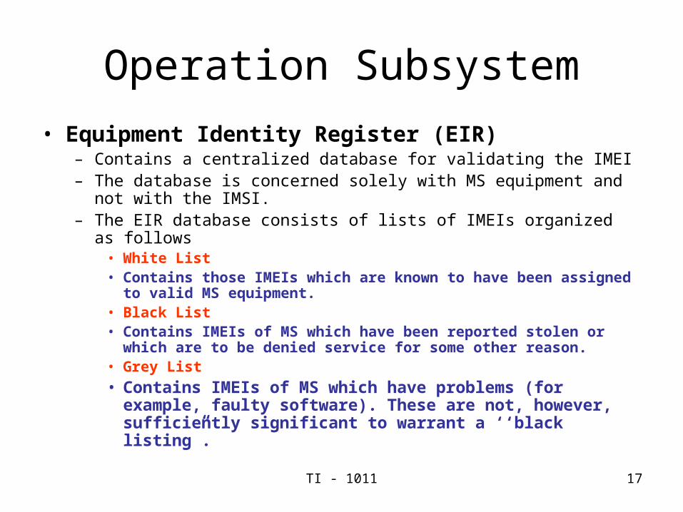
• Equipment Identity Register (EIR)– Contains a centralized database for validating the IMEI– The database is concerned solely with MS equipment and not with the
IMSI.– The EIR database consists of lists of IMEIs organized as follows
• White List• Contains those IMEIs which are known to have been assigned to valid
MS equipment.• Black List• Contains IMEIs of MS which have been reported stolen or which are to
be denied service for some other reason.• Grey List
• Contains IMEIs of MS which have problems (for example, faulty software). These are not, however, sufficiently significant to warrant a ‘‘black listing”.
TI - 1011 18
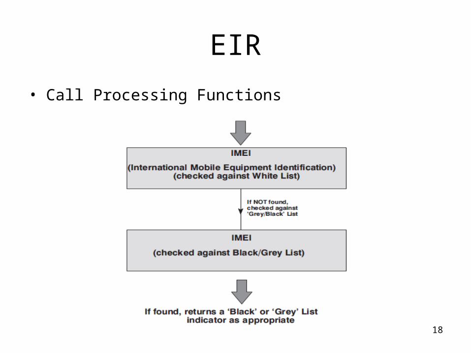
EIR
• Call Processing Functions
TI - 1011 19
Operation Subsystem
• Operation and Maintenance Center (OMC)
– The Operations and Maintenance Centre (OMC) is a centralized facility that supports the day to day management of a cellular network as well as providing a database for long term network engineering and planning tools. An OMC manages a certain area of the PLMN thus giving regionalized network management.
TI - 1011 20
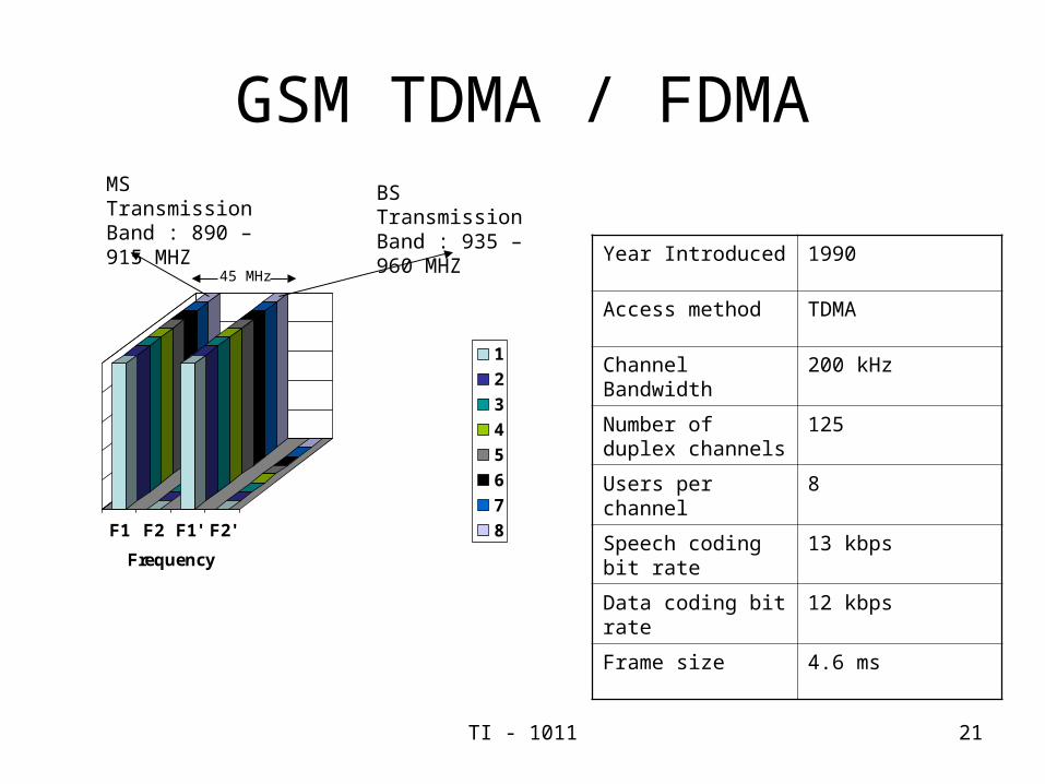
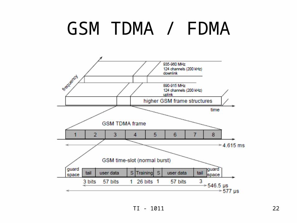
GSM Interfaces• The Um Radio Interface (MS to BTS)• Uses Physical FDMA/TDMA/FDD physical• In 900 MHz band: 890-915 MHz Uplink band, 935-960 MHz Downlink• Radio carrier is a 200kHz channel => 125 pairs of radio channels• Called Absolute Radio Frequency Channel Number (ARFCN)• ARFCN numbers given by f(n) = 890 +.2n MHz for Uplink band n = 0,…124• Corresponding downlink is f(n) + 45 MHz• Channels and ARFCN slightly different in other frequency bands• A TDMA frame is defined on the radio carrier (8 users per carrier)• Channel rate is 270.833 kbps• Two types of logical channels map onto physical channels• Control Channels (call setup, power adjustment, etc..)• Traffic Channels (voice or data) = 22.8kbps = 1 slot in a TDMA frame
TI - 1011 21
GSM TDMA / FDMA
F1 F2 F1' F2'
Frequency
1
2
3
4
5
6
7
8
45 MHz
BS Transmission Band : 935 – 960 MHZ
MS Transmission Band : 890 – 915 MHZ
Year Introduced 1990
Access method TDMA
Channel Bandwidth 200 kHz
Number of duplex channels
125
Users per channel 8
Speech coding bit rate
13 kbps
Data coding bit rate 12 kbps
Frame size 4.6 ms
TI - 1011 22
GSM TDMA / FDMA
TI - 1011 23
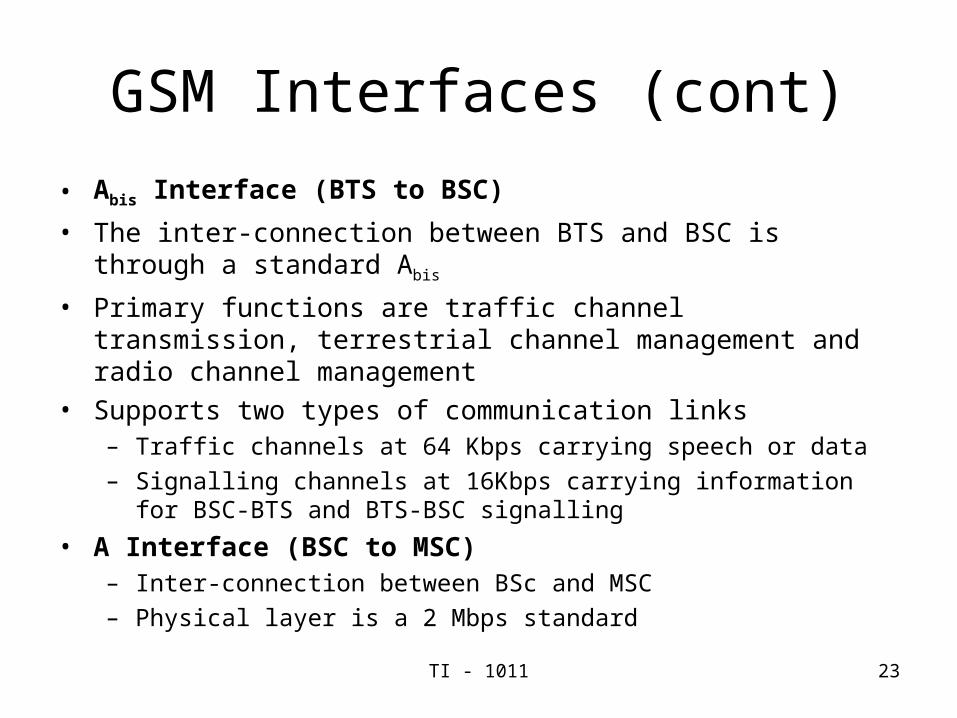
GSM Interfaces (cont)
• Abis Interface (BTS to BSC)
• The inter-connection between BTS and BSC is through a standard Abis
• Primary functions are traffic channel transmission, terrestrial channel management and radio channel management
• Supports two types of communication links– Traffic channels at 64 Kbps carrying speech or data
– Signalling channels at 16Kbps carrying information for BSC-BTS and BTS-BSC signalling
• A Interface (BSC to MSC)– Inter-connection between BSc and MSC
– Physical layer is a 2 Mbps standard
TI - 1011 24
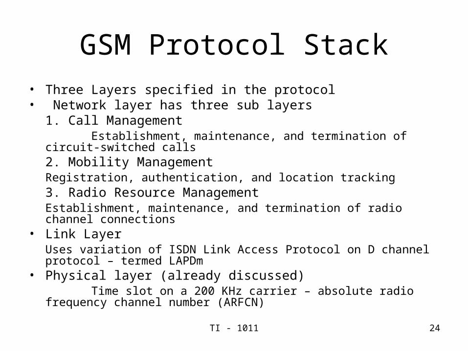
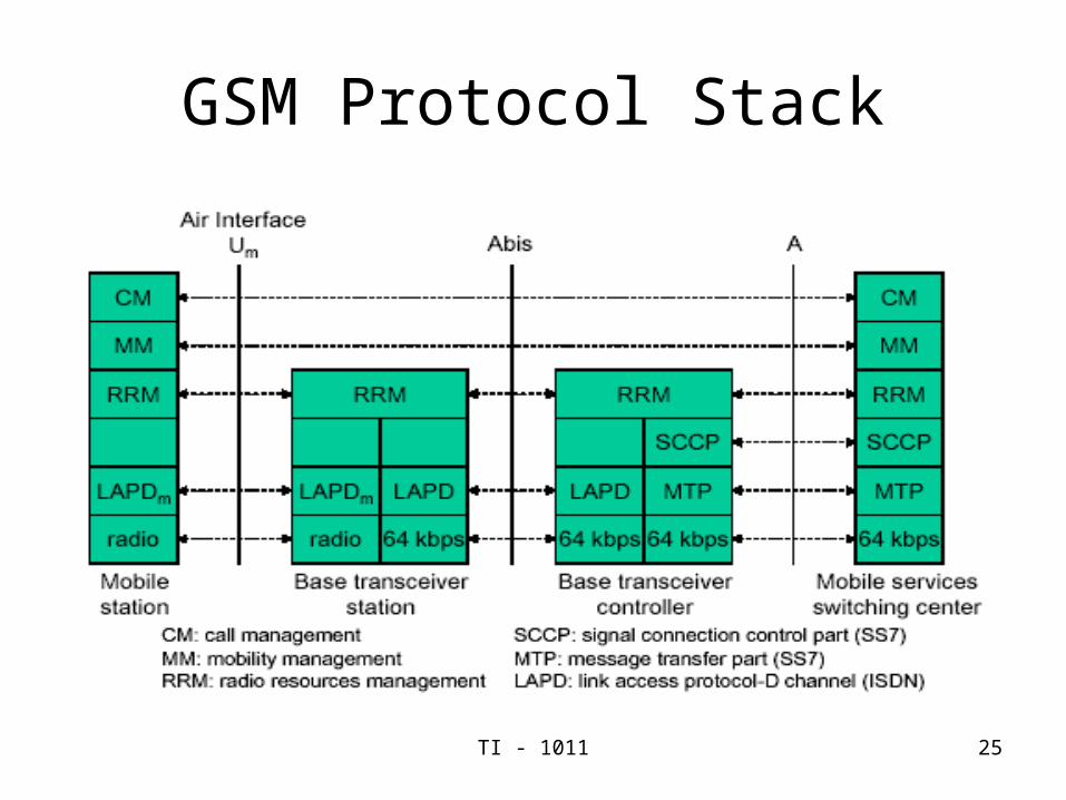
GSM Protocol Stack• Three Layers specified in the protocol• Network layer has three sub layers
1. Call Management Establishment, maintenance, and termination of circuit-switched calls2. Mobility Management
Registration, authentication, and location tracking3. Radio Resource Management
Establishment, maintenance, and termination of radio channel connections
• Link LayerUses variation of ISDN Link Access Protocol on D channel protocol
– termed LAPDm• Physical layer (already discussed)
Time slot on a 200 KHz carrier – absolute radio frequency channel number (ARFCN)
TI - 1011 25
GSM Protocol Stack
TI - 1011 26
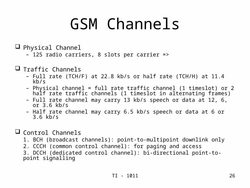
GSM Channels Physical Channel
– 125 radio carriers, 8 slots per carrier =>
Traffic Channels – Full rate (TCH/F) at 22.8 kb/s or half rate (TCH/H) at 11.4 kb/s– Physical channel = full rate traffic channel (1 timeslot) or 2 half rate
traffic channels (1 timeslot in alternating frames)– Full rate channel may carry 13 kb/s speech or data at 12, 6, or 3.6 kb/s– Half rate channel may carry 6.5 kb/s speech or data at 6 or 3.6 kb/s
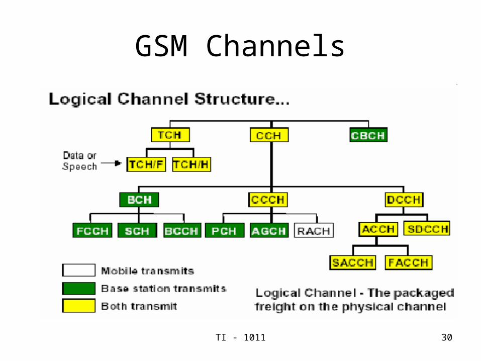
Control Channels1. BCH (broadcast channels): point-to-multipoint downlink only2. CCCH (common control channel): for paging and access3. DCCH (dedicated control channel): bi-directional point-to-point signalling
TI - 1011 27
Control Channels
• Broadcast Channels (BCH): Point-to-multipoint unidirectional channels– Frequency Correction Channel (FCCH): correcting mobile
frequency in downlink.• This channel is required for the correct operation of the radio sub-
system and allow an MS accurately turn to a BS
– Synchronization Channel (SCH): Frame synchronization• The SCH has a 64-bit binary sequence known to the MS
• MS achieves the exact timing synchronization with respect to the GSM frame by correlating the bits with the internally stored 64-bits.
– Broadcast Control Channel (BCCH): control channel structure
TI - 1011 28
Control Channels (cont.)
• Common Control Channel (CCCH): Point-to-multipoint bidirectional channels– Paging Control Channel (PCH): Downlink
• Used to page MS
– Random Access Channel (RACH): Uplink• Used to request assignment of DCCH
– Access Grant Channel (AGCH): Downlink• Used to assign an MS to a specific DCCH
• Dedicated Control Channel (DCCH): Used for signalling and control after call establishment– Stand Alone dedicated control channel (SDCCH):
• Used for authentication of MS, location updates, assignments to TCH

TI - 1011 29
Control Channels (cont.)
• Slow Associated Control Channel (SACCH):– Used to carry general control information
• Fast Associated Control Channel (FACCH):– Used to transmit handoff orders.
TI - 1011 30
GSM Channels
TI - 1011 31
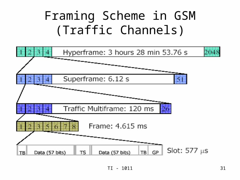
Framing Scheme in GSM (Traffic Channels)

TI - 1011 32
END