north total station nxr series - north surveying nxr total station operation manual en.pdf · north...
TRANSCRIPT
North Total Station NXR Series
1
No
rt
h G
ro
up
LT
D.
Content
Index.................................................................................................................................................... 1
General handing Precautions ............................................................................................................. 4
Safety Cautions ................................................................................................................................... 6
1. Nomenclature and functions.................................................................................................... 10
1.1 Nomenclature ................................................................................................................... 10
1.2 Functions of keys .............................................................................................................. 12
1.3 Display ............................................................................................................................... 13
1.4 Functional Keys ................................................................................................................. 13
1.5 Star Key Mode (★) ........................................................................................................... 15
2. INITIAL SETTINGS ...................................................................................................................... 20
2.1 Power ON/OFF .................................................................................................................. 20
2.2 About Battery ................................................................................................................... 20
2.2.2 Replace the Battery .................................................................................................. 22
2.2.3 Recharge the battery ................................................................................................ 22
2.3 How to input Number and Alphabet ............................................................................... 23
3. PREPARATION FOR MEASUREMENT ........................................................................................ 24
3.1 Unpacking and store of instrument ................................................................................. 24
3.2 Setting up the instrument ................................................................................................ 24
3.3 Centering position and leveling up .................................................................................. 24
3.4 Setting of tilt correction on vertical angle ....................................................................... 25
3.5 Reflecting prism ................................................................................................................ 26
4. ANGLE MEASUREMENT MODE................................................................................................. 27
4.1 Measuring horizontal angle between two points ........................................................... 27
4.2 Set the Horizontal Angle to a Required Value ................................................................. 28
4.2.1 Setting by Inputting through the Keyboard ............................................................. 28
4.2.2 Setting by [Hold] ....................................................................................................... 29
4.3 Shift the horizontal angle (Right/Left) ............................................................................. 30
5. DISTANCE MEASUREMENT ....................................................................................................... 31
5.1 Distance Measurement .................................................................................................... 32
5.2 Setting Measurement Mode ............................................................................................ 33
North Total Station NXR Series
2
No
rt
h G
ro
up
LT
D.
5.3 Select Distance unit by soft keys (m/ft/ft-in) .................................................................. 33
5.4 SetOut ............................................................................................................................... 34
5.5 Offset Measurement ........................................................................................................ 35
5.5.1 Distance Offset Measurement Mode ...................................................................... 36
5.5.2 Angle Offset Measurement Mode ........................................................................... 38
5.5.3 Plane Offset Measurement Mode............................................................................ 40
5.5.4 Column Offset Measurement Mode ........................................................................ 42
6. COORDINATES MEASUREMENT ............................................................................................... 45
6.1 Setting coordinates of the Occupied Point ...................................................................... 48
6.2 Setting Instrument Height and Target Height ................................................................. 50
7. DATA COLLECTION .................................................................................................................... 51
7.1 Selecting a file for data collection .................................................................................... 51
7.2 Setup Station .................................................................................................................... 52
7.2.1 Setting the occupied point from data stored in the internal memory ................... 53
7.2.2 Setting the occupied point by direct key input ....................................................... 55
7.3 Setting the Azimuth (Backsight Point) ............................................................................. 56
7.3.1 Setting the Backsight point from data stored in the internal memory ................. 57
7.3.2 Setting the Backsight point by direct key input....................................................... 59
7.4 Sequence of Collection ..................................................................................................... 60
7.5 Measuring and saving the data ........................................................................................ 61
8. Setout measurement ................................................................................................................ 63
8.1 Preparation ....................................................................................................................... 63
8.2 Coordinates Setout Measurement ................................................................................... 65
8.2.1 Direct input of coordinate values ............................................................................ 66
8.2.2 Obtaining point from internal memory ................................................................... 67
8.3 Intersection ....................................................................................................................... 69
8.3.1 Coordinate Intersection............................................................................................ 70
8.3.2 Precautions when performing intersection ............................................................. 73
9. FILE MANAGER (Fileman) ......................................................................................................... 75
9.1 File manager ..................................................................................................................... 75
9.1.1 Create a new file ....................................................................................................... 75
North Total Station NXR Series
3
No
rt
h G
ro
up
LT
D.
9.1.2 Delete file .................................................................................................................. 77
9.2 Data Import ....................................................................................................................... 78
9.3 Export Data ....................................................................................................................... 80
9.4 Disk format ....................................................................................................................... 82
9.5 Checking available memory ............................................................................................. 83
10. MEASUREMENT PROGRAM MODE ...................................................................................... 84
10.1 Remote Height Measurement (REM) ............................................................................... 84
10.1.1 Ground to target ....................................................................................................... 84
10.1.2 Point to point ............................................................................................................ 86
10.2 Missing line measurement (MLM) ................................................................................... 87
10.3 Setting Z coordinate of occupied point ............................................................................ 89
10.4 Area ................................................................................................................................... 91
10.4.1 Area calculation from measured data ..................................................................... 91
10.4.2 Area calculation from Coordinate data file ............................................................. 93
10.5 Roadway ........................................................................................................................... 94
11. PARAMETER ........................................................................................................................ 100
11. SPECIFICATION .......................................................................................................................... 101
12. PROMPT, WARNING AND ERROR MESSAGES ......................................................................... 104
North Total Station NXR Series
4
No
rt
h G
ro
up
LT
D.
Thank you for purchasing NORTH NXR Series Total Station. For the best performance of the
instruments, please carefully read these instructions and keep them in a convenient location for
future reference.
General handing Precautions
Before starting work or operation, be sure to check that the instrument is working correctly with
normal performance.
Do not immerse the instrument into the water
The instrument must not be submerged underwater.
The instrument is designed based on the International Standard IP54; therefore it is protected
from the normal rainfall.
Setting the instrument on a tripod
When mounting the instrument on a tripod, use a wooden tripod when possible. The vibrations
that may occur when using a metallic tripod can affect the measuring precision.
Installing the tribrach
If the tribrach is installed incorrectly, the measuring precision could be affected.
Occasionally check the adjusting screws on the tribrach. Make sure the base fixing lever is locked
and the base fixing screws are tightened.
Guarding the instrument against shocks
When transporting the instrument, provide some protection to minimize risk of shocks.
Heavy shocks may cause the measurement to be faulty.
Carrying the instrument
Always carry the instrument by its handgrip.
Do not expose the instrument to extreme heat
Do not leave the instrument in extreme heat for longer than necessary. It could adversely affect its
performance.
Sudden changes of temperature
North Total Station NXR Series
5
No
rt
h G
ro
up
LT
D.
Any sudden change of temperature to the instrument or prism may result in a reduction of
measuring distance range, i.e. when taking the instrument out from a heated vehicle. Let
instrument acclimate itself to ambient temperature.
Battery level check
Confirm battery level remaining before operating.
Taking the battery out
It is recommended not to take the battery or external battery out while the power is on. All the
data stored is possible gone at that time. So please do your assembling or taking the battery out
after the power is off.
Do not hold the lower part of display unit
When you take out the instrument from a carrying case, or keep into the case, please hold the
hand grip and base of the instrument. Please do not hold the lower part of the display unit.
External power source
Use only recommended batteries or external power source. Use of batteries or an external power
source not recommended by us may result in equipment failure.
(For further information see the chapter '2.2 About the Battery.').
Display for Safe Use
In order to encourage the safe use of products and prevent any danger to the operator and others
or damage to properties, important warnings are put on the products and inserted in the
instruction manuals. These are indicated by an exclamation point within a triangle used with
WARNING and CAUTION statements in this manual.
We suggest that everyone understand the meaning of the following displays and icons before
reading the “Safety Cautions” and manual’s main text.
WARNING: Ignoring or disregard of this display may lead to the danger or death or serious
injury.
North Total Station NXR Series
6
No
rt
h G
ro
up
LT
D.
CAUTION: Ignoring or disregard of this display may lead to personal injury or physical
damage.
Injury refers to hurt, burn, electric shock, etc.
Physical damage refers to extensive damage to buildings or equipment and furniture.
Safety Cautions
WARNING
There is a risk of fire, electric shock or physical harm if you attempt to disassemble or repair the
instrument yourself
This is only to be carried out by North Group Support or an authorized dealer.
Cause eye injury or blindness
Do not use the equipment to collimate the sun directly. The eye injury or blind could result.
Continuously looking straight at the laser beam is harmful.
High temperature may cause fire
Do not cover the charger while it is charging.
Do not close the instrument to burning gas or liquid, and do not use the instrument in coal mine.
Blast could be result.
Risk of fire or electric shock
Do not use damaged power cable, plug and socket.
Do not use a wet battery or charger.
Do not use any power voltage except the one given on manufacturer’s instructions.
Do not use an AC cable incompatible with the power supply voltage in use.
North Total Station NXR Series
7
No
rt
h G
ro
up
LT
D.
May ignite explosively
Never use an instrument near flammable gas, liquid matter, and do not use in a coal mine.
Battery can cause explosion or injury
Do not dispose in fire or heat.
Do not use any other type of charger other than the one specified.
The short circuit of a battery can cause a fire
Do not short circuit battery when storing it.
CAUTION
Do not stare at the object which reflects the laser beam. When the laser is switched on (under
EDM mode), do not look at it on the optical path or near the prism. It is only allowed to observe
the prism with the telescope of total station.
Do not connect or disconnect equipment with wet hands, you will be at risk of electric shocks if
you do.
Do not stand or sit on the carrying cases, and do not turn over the carrying case arbitrarily, the
instrument could be damaged.
Please note that the tips of tripod can be hazardous, be aware of this when setting up or carrying
the tripod.
There is risk of injury by falling down the instrument or case.
Do not use a carrying case with damaged belts, grips or latches, instrument damage could result.
Do not allow skin or clothing to come into contact with acid from the batteries, if this does occur,
then wash off with copious amounts of water and seek medical advice.
A plumb bob can cause an injury to a person if used incorrectly.
It could be dangerous if the instrument falls over, please ensure you attach a handle to the
instrument securely.
North Total Station NXR Series
8
No
rt
h G
ro
up
LT
D.
Ensure that you mount the Tribrach correctly; failing to do so may result in injury if the tribrach
were to fall over.
It could be dangerous if the instrument falls over, please check that you fix the instrument to the
tripod correctly.
There are risks of injury by falling down a tripod and an instrument.
Always check that the screws of tripod are tightened.
The battery should be disposed of safely.
The appliance is not intended for use by young children or infirm persons without supervision.
Young children should be supervised to ensure that they do not play with the appliance.
Safety Standards for Laser
This series adopt the class of Laser Product according to IEC Standard Publication 60825-1 Amd.
2:2001. According this standard, EDM device is classified as Class 3R Laser Product when
reflectorless measurement is selected, when the prism and reflective sheet is selected as target,
the output is equivalent to the safer class 1. Follow the safety instructions on the labels to ensure
safe use.
CAUTION: CLASS 3R LASER RADIATION WHEN OPEN
AVOID DIRECT EYE EXPOSURE.
CAUTION: CLASS 2 LASER RADIATION WHEN OPEN
DO NOT STARE INTO THE BEAM
WARNING
Never point the laser beam at other’s eyes, it could cause serious injury.
North Total Station NXR Series
9
No
rt
h G
ro
up
LT
D.
Never look directly into the laser beam source; it could cause permanent eye damage.
Never stare at the laser beam; it could cause permanent eye damage.
Never look at the laser beam through a telescope or other optical devices; it could cause
permanent eye damage.
When the laser beam emits on prism, mirror, metal surface, window, etc., it is dangerous to look
straight at the reflex.
User
This product is for professional use only!
The user is required to be a qualified surveyor or have a good knowledge of surveying, in order to
understand the user and safety instructions, before operating, inspecting or adjusting.
Wear the required protectors (safety shoes, helmet, etc.) when operating.
Exceptions from Responsibility
The user of this product is expected to follow all operating instructions and make periodic checks
of the product’s performance.
The manufacturer, or its representatives, assumes no responsibility for results of a faulty or
intentional usage or misuse including any direct, indirect, consequential damage, and loss of
profits.
1) The manufacturer, or its representatives, assumes no responsibility for consequential
damage, and loss of profits by any disaster, (an earthquake, storms, floods etc.). Fire,
accident or an act of a third party and/or a usage any other usual conditions.
2) The manufacturer, or its representatives, assumes no responsibility for any damage, and
loss of profits due to a change of data, loss of data, an interruption of business, etc.,
caused by using the product or an unusable product.
3) The manufacturer, or its representatives, assumes no responsibility for any damage, and
loss of profits caused by usage except for explained in the user manual.
4) The manufacturer, or its representatives, assumes no responsibility for damage caused by
wrong movement, or action due to connecting with other products.
North Total Station NXR Series
10
No
rt
h G
ro
up
LT
D.
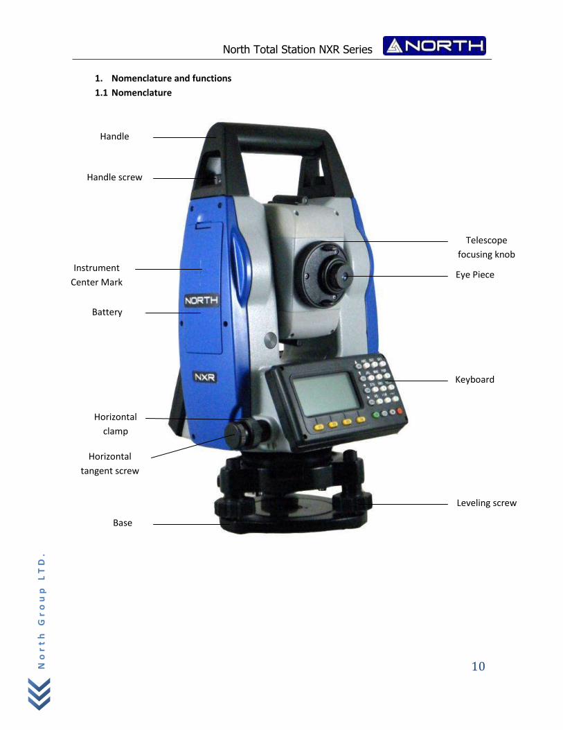
1. Nomenclature and functions
1.1 Nomenclature
Instrument
Center Mark
Telescope
focusing knob
Eye Piece
Base
Leveling screw
Horizontal
tangent screw
Keyboard
Horizontal
clamp
Battery
Handle
Handle screw
North Total Station NXR Series
11
No
rt
h G
ro
up
LT
D.
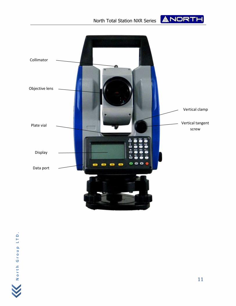
Collimator
Vertical tangent
screw
Display
Plate vial
Objective lens
Vertical clamp
Data port
North Total Station NXR Series
12
No
rt
h G
ro
up
LT
D.
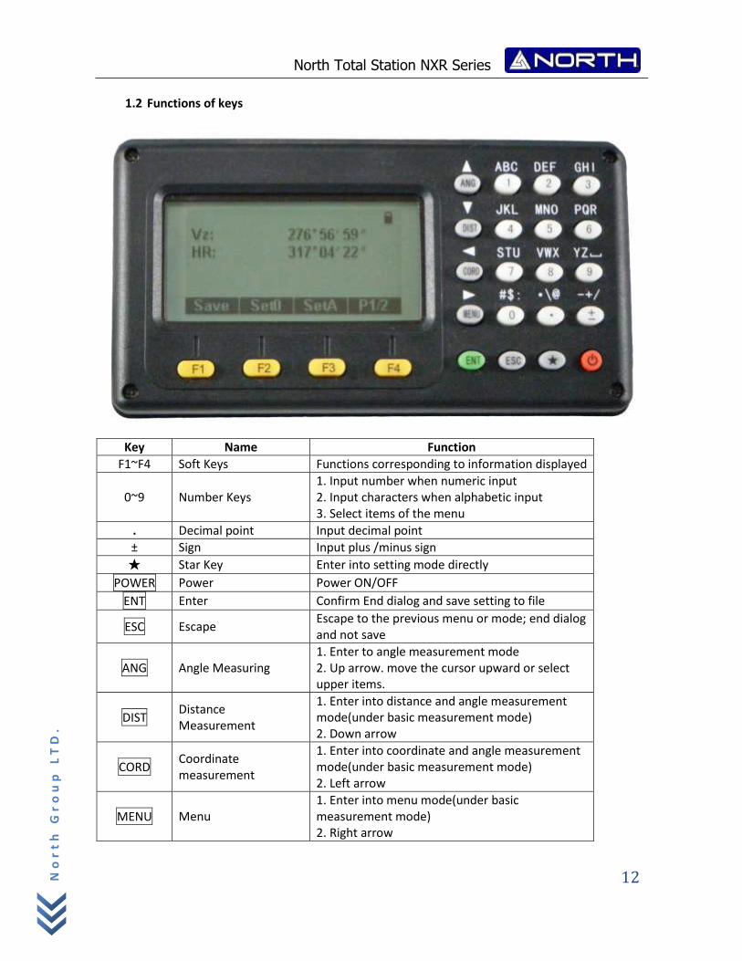
1.2 Functions of keys
Key Name Function
F1~F4 Soft Keys Functions corresponding to information displayed
0~9 Number Keys 1. Input number when numeric input 2. Input characters when alphabetic input 3. Select items of the menu
. Decimal point Input decimal point
± Sign Input plus /minus sign
★ Star Key Enter into setting mode directly
POWER Power Power ON/OFF
ENT Enter Confirm End dialog and save setting to file
ESC Escape Escape to the previous menu or mode; end dialog and not save
ANG Angle Measuring 1. Enter to angle measurement mode 2. Up arrow. move the cursor upward or select upper items.
DIST Distance Measurement
1. Enter into distance and angle measurement mode(under basic measurement mode) 2. Down arrow
CORD Coordinate measurement
1. Enter into coordinate and angle measurement mode(under basic measurement mode) 2. Left arrow
MENU Menu 1. Enter into menu mode(under basic measurement mode) 2. Right arrow
North Total Station NXR Series
13
No
rt
h G
ro
up
LT
D.
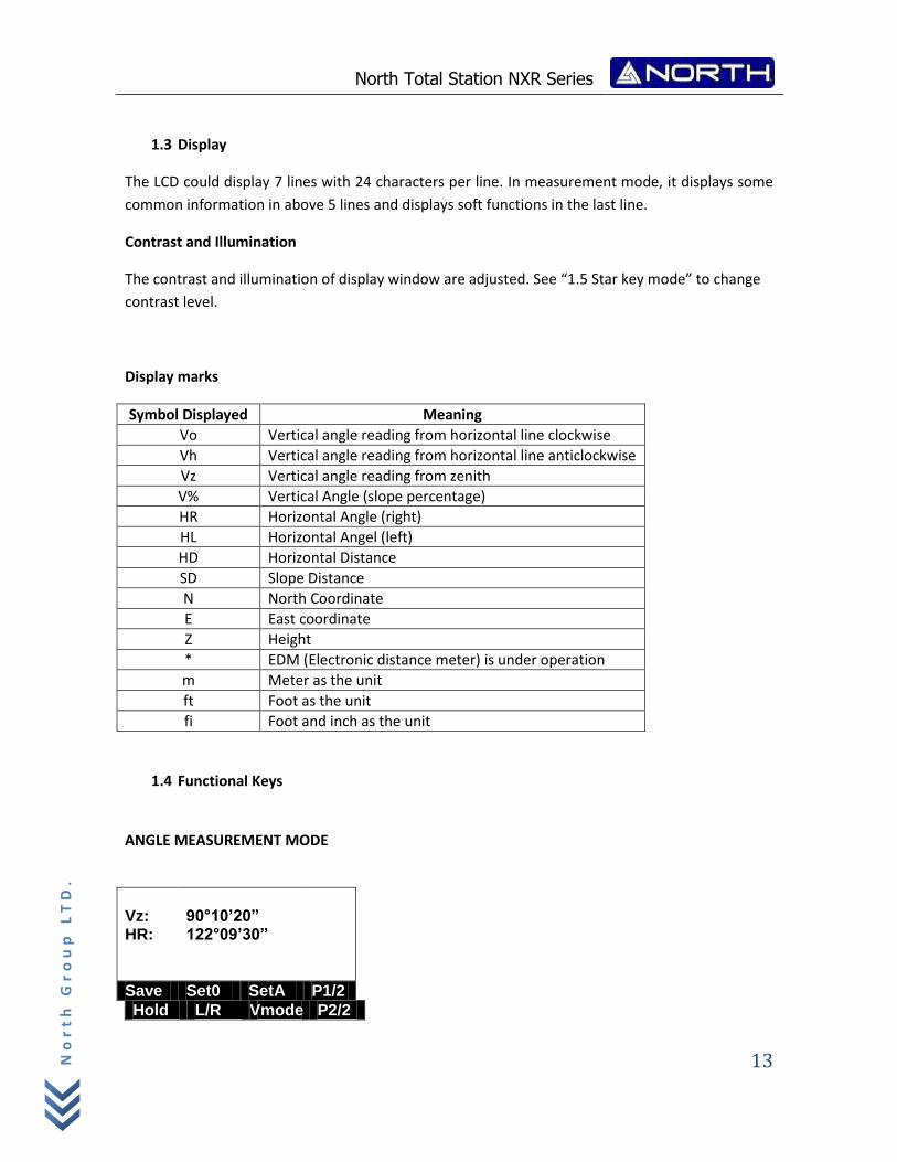
1.3 Display
The LCD could display 7 lines with 24 characters per line. In measurement mode, it displays some
common information in above 5 lines and displays soft functions in the last line.
Contrast and Illumination
The contrast and illumination of display window are adjusted. See “1.5 Star key mode” to change
contrast level.
Display marks
Symbol Displayed Meaning
Vo Vertical angle reading from horizontal line clockwise
Vh Vertical angle reading from horizontal line anticlockwise
Vz Vertical angle reading from zenith
V% Vertical Angle (slope percentage)
HR Horizontal Angle (right)
HL Horizontal Angel (left)
HD Horizontal Distance
SD Slope Distance
N North Coordinate
E East coordinate
Z Height
* EDM (Electronic distance meter) is under operation
m Meter as the unit
ft Foot as the unit
fi Foot and inch as the unit
1.4 Functional Keys ANGLE MEASUREMENT MODE
Vz: 90°10’20” HR: 122°09’30”
Save Set0 SetA P1/2
Hold L/R Vmode P2/2
North Total Station NXR Series
14
No
rt
h G
ro
up
LT
D.
Page Soft key Display Function
Page 1
F1 Save
Start angle measurement, and save the results in respective job. (Measurement files and coordinates files are selected in DATA COLLECT menu.)
F2 Set0 Set horizontal angle to 0 degree.
F3 SetA Input horizontal angle by keyboard
F4 P1/2 Display the soft key functions in Page 2.
Page 2
F1 Hold Lock the reading of horizontal angle
F2 L/R Shift between right/left angle of horizontal angle.
F3 Vmode Shift between vertical angle measurement mode
F4 P2/2 Display the soft key functions on Page 3.
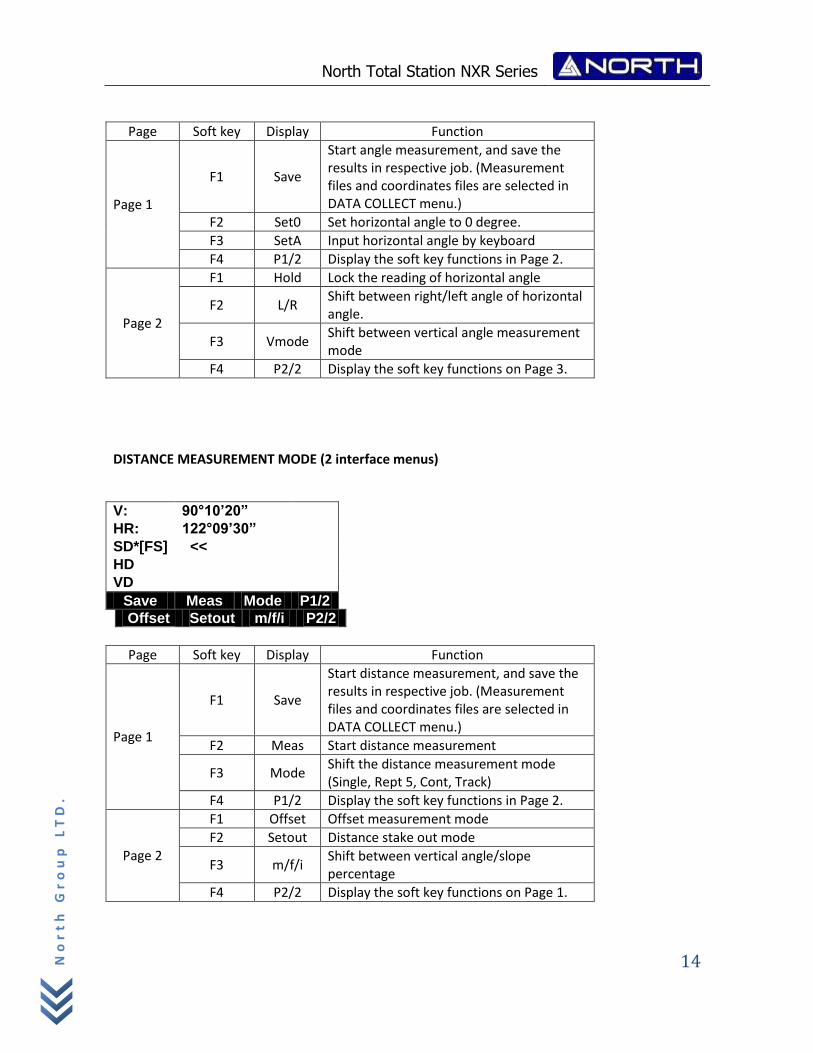
DISTANCE MEASUREMENT MODE (2 interface menus)
V: 90°10’20” HR: 122°09’30” SD*[FS] << HD VD
Save Meas Mode P1/2
Offset Setout m/f/i P2/2
Page Soft key Display Function
Page 1
F1 Save
Start distance measurement, and save the results in respective job. (Measurement files and coordinates files are selected in DATA COLLECT menu.)
F2 Meas Start distance measurement
F3 Mode Shift the distance measurement mode (Single, Rept 5, Cont, Track)
F4 P1/2 Display the soft key functions in Page 2.
Page 2
F1 Offset Offset measurement mode
F2 Setout Distance stake out mode
F3 m/f/i Shift between vertical angle/slope percentage
F4 P2/2 Display the soft key functions on Page 1.
North Total Station NXR Series
15
No
rt
h G
ro
up
LT
D.
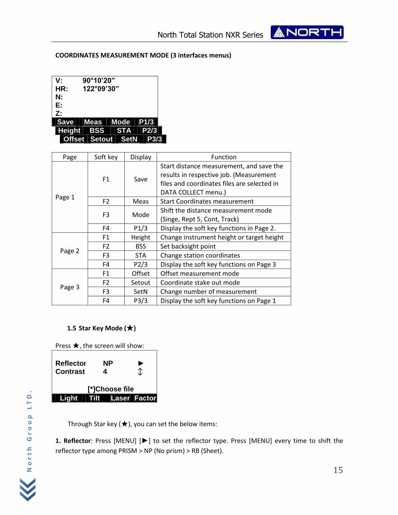
COORDINATES MEASUREMENT MODE (3 interfaces menus)
V: 90°10’20” HR: 122°09’30” N: E: Z:
Save Meas Mode P1/3
Height BSS STA P2/3
Offset Setout SetN P3/3
Page Soft key Display Function
Page 1
F1 Save
Start distance measurement, and save the results in respective job. (Measurement files and coordinates files are selected in DATA COLLECT menu.)
F2 Meas Start Coordinates measurement
F3 Mode Shift the distance measurement mode (Singe, Rept 5, Cont, Track)
F4 P1/3 Display the soft key functions in Page 2.
Page 2
F1 Height Change instrument height or target height
F2 BSS Set backsight point
F3 STA Change station coordinates
F4 P2/3 Display the soft key functions on Page 3
Page 3
F1 Offset Offset measurement mode
F2 Setout Coordinate stake out mode
F3 SetN Change number of measurement
F4 P3/3 Display the soft key functions on Page 1
1.5 Star Key Mode (★)
Press ★, the screen will show:
Reflector NP ► Contrast 4 ↕ [*]Choose file
Light Tilt Laser Factor
Through Star key (★), you can set the below items:
1. Reflector: Press [MENU] [►] to set the reflector type. Press [MENU] every time to shift the
reflector type among PRISM > NP (No prism) > RB (Sheet).
North Total Station NXR Series
16
No
rt
h G
ro
up
LT
D.
2. Contrast: Press [▲], or [▼] you can adjust the contrast of the LCD.
3. Backlight:
Press [F1]: Turn on the background light.
Press [F1] again: Turn off the background light.
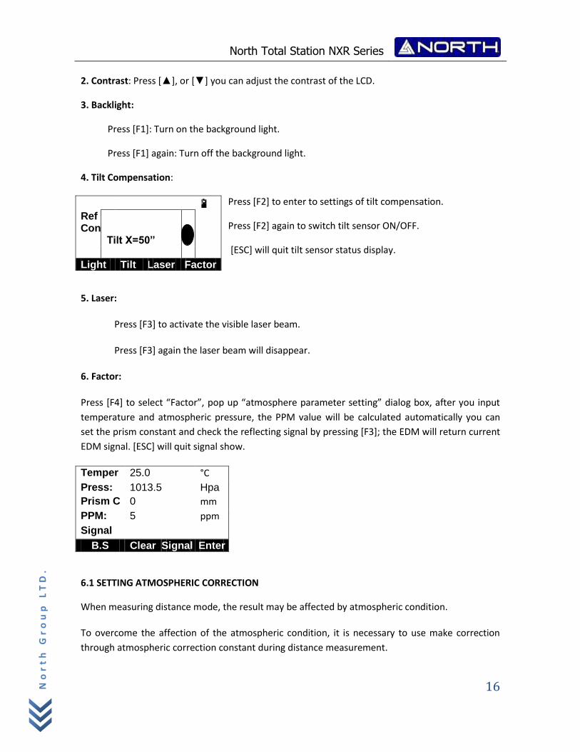
4. Tilt Compensation:
Press [F2] to enter to settings of tilt compensation.
Press [F2] again to switch tilt sensor ON/OFF.
[ESC] will quit tilt sensor status display.
5. Laser:
Press [F3] to activate the visible laser beam.
Press [F3] again the laser beam will disappear.
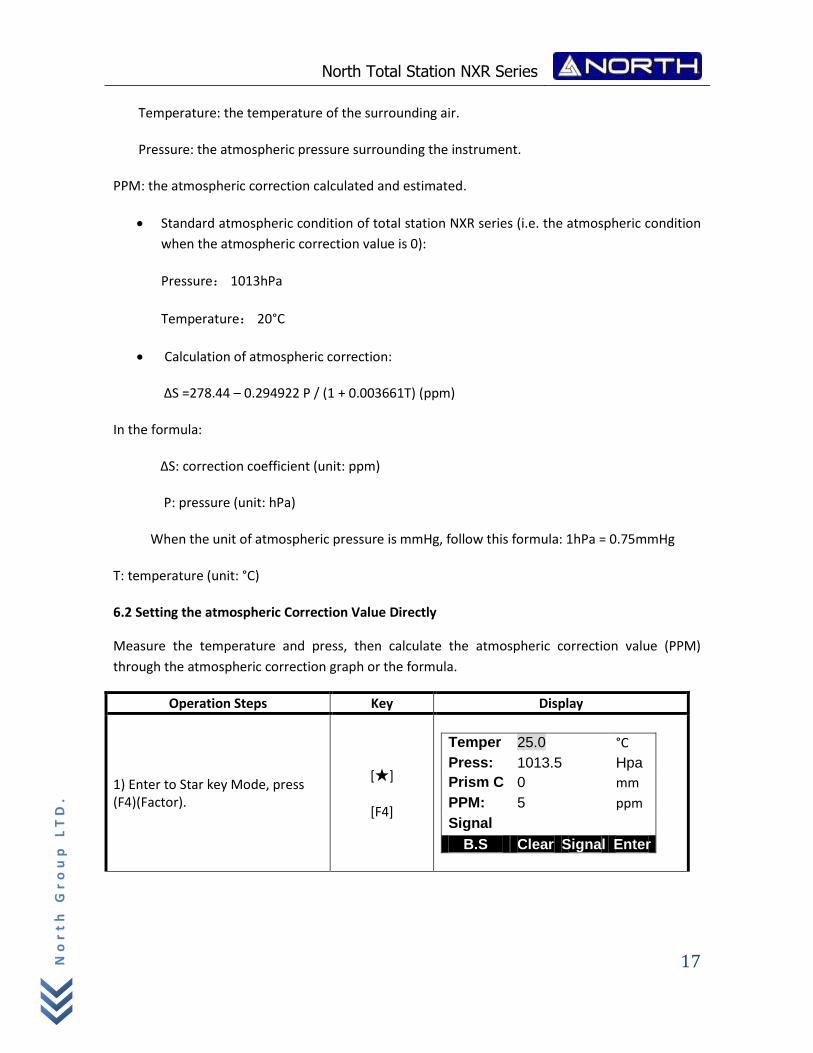
6. Factor:
Press [F4] to select “Factor”, pop up “atmosphere parameter setting” dialog box, after you input
temperature and atmospheric pressure, the PPM value will be calculated automatically you can
set the prism constant and check the reflecting signal by pressing [F3]; the EDM will return current
EDM signal. [ESC] will quit signal show.
Temper 25.0 °C
Press: 1013.5 Hpa
Prism C 0 mm
PPM: 5 ppm
Signal
B.S Clear Signal Enter
6.1 SETTING ATMOSPHERIC CORRECTION
When measuring distance mode, the result may be affected by atmospheric condition.
To overcome the affection of the atmospheric condition, it is necessary to use make correction
through atmospheric correction constant during distance measurement.
Ref Con Tilt X=50”
Light Tilt Laser Factor
North Total Station NXR Series
17
No
rt
h G
ro
up
LT
D.
Temperature: the temperature of the surrounding air.
Pressure: the atmospheric pressure surrounding the instrument.
PPM: the atmospheric correction calculated and estimated.
Standard atmospheric condition of total station NXR series (i.e. the atmospheric condition
when the atmospheric correction value is 0):
Pressure: 1013hPa
Temperature: 20°C
Calculation of atmospheric correction:
ΔS =278.44 – 0.294922 P / (1 + 0.003661T) (ppm)
In the formula:
ΔS: correction coefficient (unit: ppm)
P: pressure (unit: hPa)
When the unit of atmospheric pressure is mmHg, follow this formula: 1hPa = 0.75mmHg
T: temperature (unit: °C)
6.2 Setting the atmospheric Correction Value Directly
Measure the temperature and press, then calculate the atmospheric correction value (PPM)
through the atmospheric correction graph or the formula.
Operation Steps Key Display
1) Enter to Star key Mode, press (F4)(Factor).
[★]
[F4]
Temper 25.0 °C
Press: 1013.5 Hpa
Prism C 0 mm
PPM: 5 ppm
Signal
B.S Clear Signal Enter
North Total Station NXR Series
18
No
rt
h G
ro
up
LT
D.
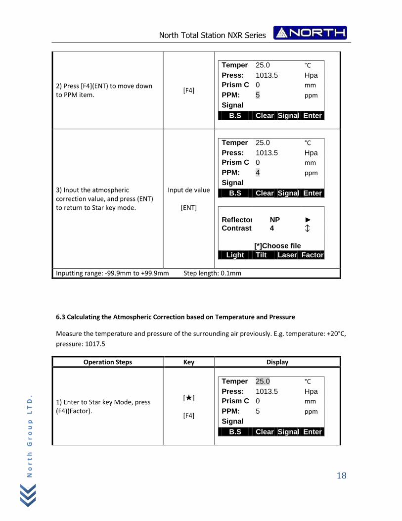
2) Press [F4](ENT) to move down to PPM item.
[F4]
Temper 25.0 °C
Press: 1013.5 Hpa
Prism C 0 mm
PPM: 5 ppm
Signal
B.S Clear Signal Enter
3) Input the atmospheric correction value, and press (ENT) to return to Star key mode.
Input de value
[ENT]
Temper 25.0 °C
Press: 1013.5 Hpa
Prism C 0 mm
PPM: 4 ppm
Signal
B.S Clear Signal Enter
Reflector NP ► Contrast 4 ↕ [*]Choose file
Light Tilt Laser Factor
Inputting range: ‐99.9mm to +99.9mm Step length: 0.1mm
6.3 Calculating the Atmospheric Correction based on Temperature and Pressure
Measure the temperature and pressure of the surrounding air previously. E.g. temperature: +20°C,
pressure: 1017.5
Operation Steps Key Display
1) Enter to Star key Mode, press (F4)(Factor).
[★]
[F4]
Temper 25.0 °C
Press: 1013.5 Hpa
Prism C 0 mm
PPM: 5 ppm
Signal
B.S Clear Signal Enter
North Total Station NXR Series
19
No
rt
h G
ro
up
LT
D.
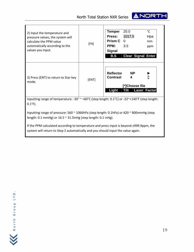
2) Input the temperature and pressure values, the system will calculate the PPM value automatically according to the values you input.
[F4]
Temper 20.0 °C
Press: 1017.5 Hpa
Prism C 0 mm
PPM: 3.5 ppm
Signal
B.S Clear Signal Enter
3) Press (ENT) to return to Star key mode.
[ENT]
Reflector NP ► Contrast 4 ↕ [*]Choose file
Light Tilt Laser Factor
Inputting range of temperature: ‐30° ~ +60°C (step length: 0.1°C) or ‐22~+140°F (step length:
0.1°F).
Inputting range of pressure: 560 ~ 1066hPa (step length: 0.1hPa) or 420 ~ 800mmHg (step
length: 0.1 mmHg) or 16.5 ~ 31.5inHg (step length: 0.1 inHg).
If the PPM calculated according to temperature and press input is beyond ±999.9ppm, the
system will return to Step 2 automatically and you should input the value again.
North Total Station NXR Series
20
No
rt
h G
ro
up
LT
D.
2. INITIAL SETTINGS
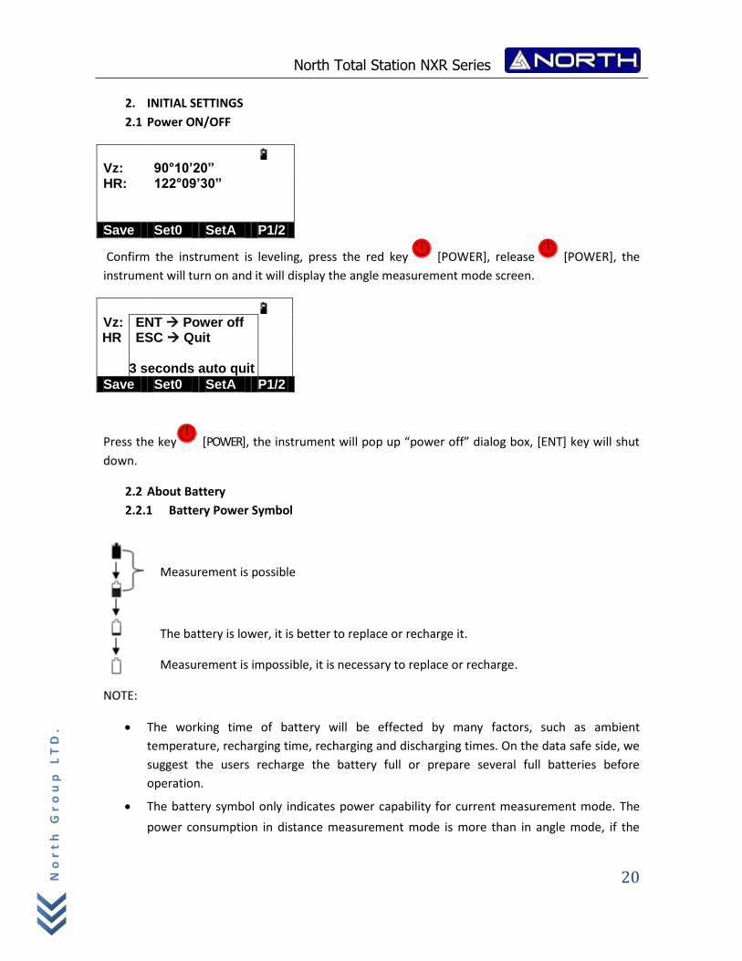
2.1 Power ON/OFF
Vz: 90°10’20” HR: 122°09’30”
Save Set0 SetA P1/2
Confirm the instrument is leveling, press the red key [POWER], release [POWER], the
instrument will turn on and it will display the angle measurement mode screen.
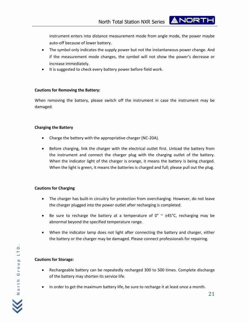
Vz: ENT Power off HR ESC Quit 3 seconds auto quit
Save Set0 SetA P1/2
Press the key [POWER], the instrument will pop up “power off” dialog box, [ENT] key will shut
down.
2.2 About Battery
2.2.1 Battery Power Symbol
Measurement is possible
The battery is lower, it is better to replace or recharge it.
Measurement is impossible, it is necessary to replace or recharge.
NOTE:
The working time of battery will be effected by many factors, such as ambient
temperature, recharging time, recharging and discharging times. On the data safe side, we
suggest the users recharge the battery full or prepare several full batteries before
operation.
The battery symbol only indicates power capability for current measurement mode. The
power consumption in distance measurement mode is more than in angle mode, if the
North Total Station NXR Series
21
No
rt
h G
ro
up
LT
D.
instrument enters into distance measurement mode from angle mode, the power maybe
auto-off because of lower battery.
The symbol only indicates the supply power but not the instantaneous power change. And
if the measurement mode changes, the symbol will not show the power’s decrease or
increase immediately.
It is suggested to check every battery power before field work.
Cautions for Removing the Battery:
When removing the battery, please switch off the instrument in case the instrument may be
damaged.
Charging the Battery
Charge the battery with the appropriative charger (NC‐20A).
Before charging, link the charger with the electrical outlet first. Unload the battery from
the instrument and connect the charger plug with the charging outlet of the battery.
When the indicator light of the charger is orange, it means the battery is being charged.
When the light is green, it means the batteries is charged and full; please pull out the plug.
Cautions for Charging
The charger has built‐in circuitry for protection from overcharging. However, do not leave
the charger plugged into the power outlet after recharging is completed.
Be sure to recharge the battery at a temperature of 0° ~ ±45°C, recharging may be
abnormal beyond the specified temperature range.
When the indicator lamp does not light after connecting the battery and charger, either
the battery or the charger may be damaged. Please connect professionals for repairing.
Cautions for Storage:
Rechargeable battery can be repeatedly recharged 300 to 500 times. Complete discharge
of the battery may shorten its service life.
In order to get the maximum battery life, be sure to recharge it at least once a month.
North Total Station NXR Series
22
No
rt
h G
ro
up
LT
D.
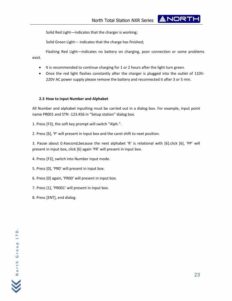
2.2.2 Replace the Battery
1. Remove the battery.
2. Press the button downward as shown left.
3. Remove the battery by pulling it toward you.
2.2.3 Recharge the battery
Mount the battery
Insert the battery to the instrument
Press the top of the battery until you hear a click.
As above figures show, connect the charger and the battery, then plug the charger into the outlet
of 110V-220V AC power supply, recharging will begin.
NOTE:
The indicator light on the charger will illuminate three separate colors for varies mode
conditions:
North Total Station NXR Series
23
No
rt
h G
ro
up
LT
D.
Solid Red Light—indicates that the charger is working;
Solid Green Light— indicates that the charge has finished;
Flashing Red Light—indicates no battery on charging, poor connection or some problems
exist.
It is recommended to continue charging for 1 or 2 hours after the light turn green.
Once the red light flashes constantly after the charger is plugged into the outlet of 110V-
220V AC power supply please remove the battery and reconnected it after 3 or 5 min.
2.3 How to input Number and Alphabet
All Number and alphabet inputting must be carried out in a dialog box. For example, input point
name PR001 and STN -123.456 in “Setup station” dialog box.
1. Press [F3], the soft key prompt will switch “Alph.”.
2. Press [6], ’P’ will present in input box and the caret shift to next position.
3. Pause about 0.4second,because the next alphabet ‘R’ is relational with [6].click [6], ’PP’ will
present in input box, click [6] again ‘PR’ will present in input box.
4. Press [F3], switch into Number input mode.
5. Press [0], ’PR0’ will present in input box.
6. Press [0] again, ’PR00’ will present in input box.
7. Press [1], ’PR001’ will present in input box.
8. Press [ENT], end dialog.
North Total Station NXR Series
24
No
rt
h G
ro
up
LT
D.
3. PREPARATION FOR MEASUREMENT
3.1 Unpacking and store of instrument
Unpacking of the instrument
Place the case lightly with the cover upward, and unlock the case, take out the instrument.
Storage of instrument
Cover the telescope cap, place the instrument into the case with the vertical clamp screw and
circular vial upwards (Objective lens towards tribrach), and slightly tighten the vertical clamp
screw and lock the case.
3.2 Setting up the instrument
Mount the battery in the instrument before performing this operation because the instrument will
tilt slightly if the battery is mounted after leveling.
I. Set up the tripod first: extend the extension legs to suitable lengths and tighten the screws on
the midsections. Make sure the legs are spaced at equal intervals and the head is approximately
level. Set the tripod so that the head is positioned over the surveying point. Make sure the tripod
shoes are firmly fixed in the ground.
II. Step on the tripod to make sure if it is well stationed on the ground.
II. Mount the instrument on the tripod head. Supporting it with one hand, tighten the centering
screw on the bottom of the unit to make sure it is secured to the tripod.
3.3 Centering position and leveling up
1. Position tripod legs so that the plummet is aimed to the ground mark point. Turn on the laser
plummet.
2. Turn three foot screws of the tribrach till the center of reticule exactly coincides with the
surveying point at any position.
3. Move the tripod legs to centre the circular level. The instrument is now roughly leveled-up.
4. Center the bubble in the circular level.
North Total Station NXR Series
25
No
rt
h G
ro
up
LT
D.
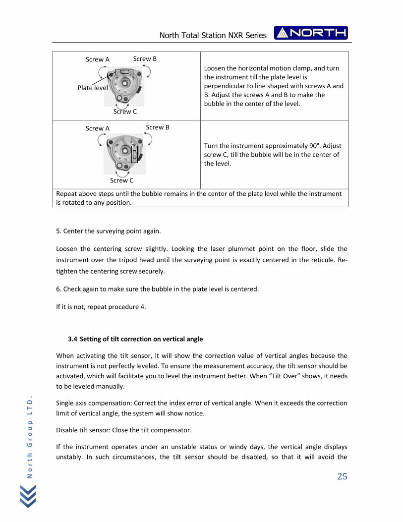
Loosen the horizontal motion clamp, and turn the instrument till the plate level is perpendicular to line shaped with screws A and B. Adjust the screws A and B to make the bubble in the center of the level.
Turn the instrument approximately 90°. Adjust
screw C, till the bubble will be in the center of the level.
Repeat above steps until the bubble remains in the center of the plate level while the instrument is rotated to any position.
5. Center the surveying point again.
Loosen the centering screw slightly. Looking the laser plummet point on the floor, slide the
instrument over the tripod head until the surveying point is exactly centered in the reticule. Re-
tighten the centering screw securely.
6. Check again to make sure the bubble in the plate level is centered.
If it is not, repeat procedure 4.
3.4 Setting of tilt correction on vertical angle
When activating the tilt sensor, it will show the correction value of vertical angles because the
instrument is not perfectly leveled. To ensure the measurement accuracy, the tilt sensor should be
activated, which will facilitate you to level the instrument better. When “Tilt Over” shows, it needs
to be leveled manually.
Single axis compensation: Correct the index error of vertical angle. When it exceeds the correction
limit of vertical angle, the system will show notice.
Disable tilt sensor: Close the tilt compensator.
If the instrument operates under an unstable status or windy days, the vertical angle displays
unstably. In such circumstances, the tilt sensor should be disabled, so that it will avoid the
Screw B Screw A
Plate level
Screw C
Screw A Screw B
Screw C
North Total Station NXR Series
26
No
rt
h G
ro
up
LT
D.
instrument from displaying error messages as well as abortion of measurement caused by the tilt
sensor exceeding the correction limit.
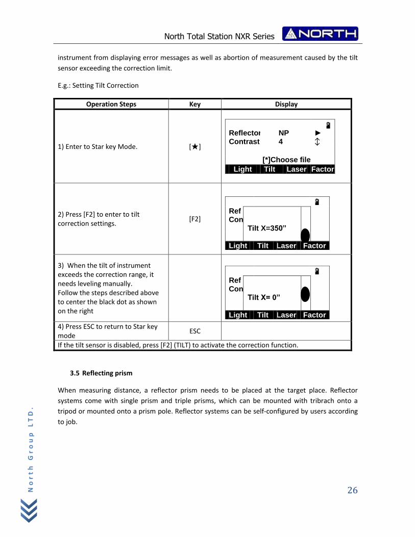
E.g.: Setting Tilt Correction
Operation Steps Key Display
1) Enter to Star key Mode. [★]
Reflector NP ► Contrast 4 ↕ [*]Choose file
Light Tilt Laser Factor
2) Press [F2] to enter to tilt correction settings.
[F2]
Ref Con Tilt X=350”
Light Tilt Laser Factor
3) When the tilt of instrument exceeds the correction range, it needs leveling manually. Follow the steps described above to center the black dot as shown on the right
Ref Con Tilt X= 0”
Light Tilt Laser Factor
4) Press ESC to return to Star key mode
ESC
If the tilt sensor is disabled, press [F2] (TILT) to activate the correction function.
3.5 Reflecting prism
When measuring distance, a reflector prism needs to be placed at the target place. Reflector
systems come with single prism and triple prisms, which can be mounted with tribrach onto a
tripod or mounted onto a prism pole. Reflector systems can be self‐configured by users according
to job.
North Total Station NXR Series
27
No
rt
h G
ro
up
LT
D.
4. ANGLE MEASUREMENT MODE
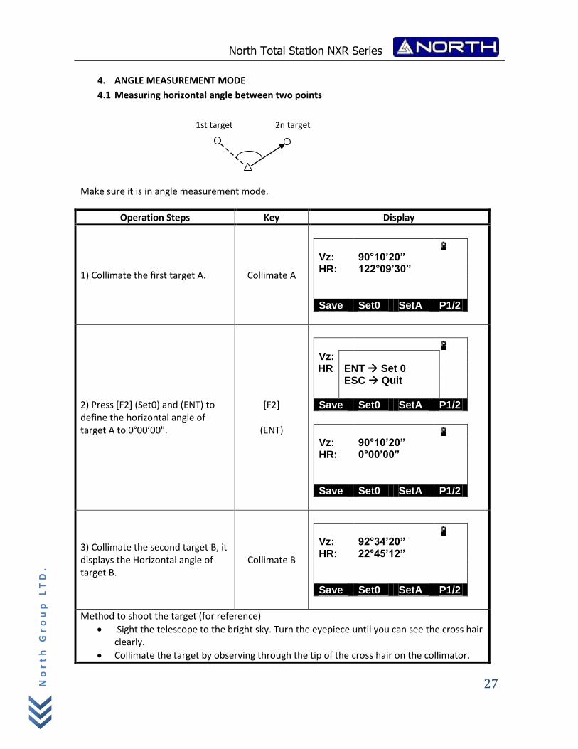
4.1 Measuring horizontal angle between two points
Make sure it is in angle measurement mode.
Operation Steps Key Display
1) Collimate the first target A. Collimate A
Vz: 90°10’20” HR: 122°09’30”
Save Set0 SetA P1/2
2) Press [F2] (Set0) and (ENT) to define the horizontal angle of target A to 0°00’00".
[F2]
(ENT)
Vz: HR ENT Set 0 ESC Quit
Save Set0 SetA P1/2
Vz: 90°10’20” HR: 0°00’00”
Save Set0 SetA P1/2
3) Collimate the second target B, it displays the Horizontal angle of target B.
Collimate B
Vz: 92°34’20” HR: 22°45’12”
Save Set0 SetA P1/2
Method to shoot the target (for reference)
Sight the telescope to the bright sky. Turn the eyepiece until you can see the cross hair clearly.
Collimate the target by observing through the tip of the cross hair on the collimator.
2n target 1st target
North Total Station NXR Series
28
No
rt
h G
ro
up
LT
D.
Keep some distance between your eyes and the collimator.
Rotate the telescope focusing knob until the object can be seen clearly.
If there are deviations when moving your eye up, down, left or right, it proves that the focus or the diopter of the eyepiece is not adjusted well, which will affect the observation accuracy. You should focus and adjust the eyepiece sleeve carefully to eliminate such errors.
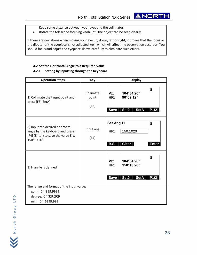
4.2 Set the Horizontal Angle to a Required Value
4.2.1 Setting by Inputting through the Keyboard
Operation Steps Key Display
1) Collimate the target point and press [F3](SetA)
Collimate point
[F3]
Vz: 104°34’20” HR: 90°09’12”
Save Set0 SetA P1/2
2) Input the desired horizontal angle by the keyboard and press [F4] (Enter) to save the value E.g. 150°10’20”.
Input ang
[F4]
Set Ang H
HR: 150.1020
B.S. Clear Enter
3) H angle is defined
Vz: 104°34’20” HR: 150°10’20”
Save Set0 SetA P1/2
The range and format of the input value:
gon: 0 ~ 399.9999
degree: 0 ~ 359.5959
mil: 0 ~ 6399.999
North Total Station NXR Series
29
No
rt
h G
ro
up
LT
D.
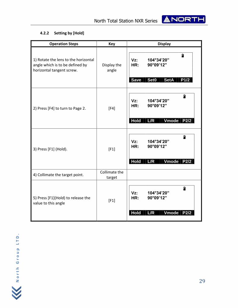
4.2.2 Setting by [Hold]
Operation Steps Key Display
1) Rotate the lens to the horizontal angle which is to be defined by horizontal tangent screw.
Display the angle
Vz: 104°34’20” HR: 90°09’12”
Save Set0 SetA P1/2
2) Press [F4] to turn to Page 2. [F4]
Vz: 104°34’20” HR: 90°09’12”
Hold L/R Vmode P2/2
3) Press [F1] (Hold). [F1]
Vz: 104°34’20” HR: 90°09’12”
Hold L/R Vmode P2/2
4) Collimate the target point. Collimate the
target
5) Press [F1](Hold) to release the value to this angle
[F1]
Vz: 104°34’20” HR: 90°09’12”
Hold L/R Vmode P2/2
North Total Station NXR Series
30
No
rt
h G
ro
up
LT
D.
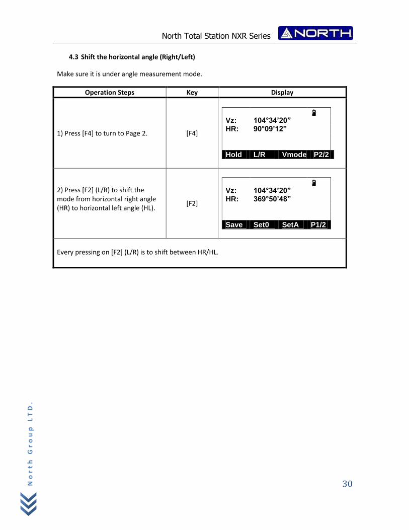
4.3 Shift the horizontal angle (Right/Left)
Make sure it is under angle measurement mode.
Operation Steps Key Display
1) Press [F4] to turn to Page 2. [F4]
Vz: 104°34’20” HR: 90°09’12”
Hold L/R Vmode P2/2
2) Press [F2] (L/R) to shift the mode from horizontal right angle (HR) to horizontal left angle (HL).
[F2]
Vz: 104°34’20” HR: 369°50’48”
Save Set0 SetA P1/2
Every pressing on [F2] (L/R) is to shift between HR/HL.
North Total Station NXR Series
31
No
rt
h G
ro
up
LT
D.
5. DISTANCE MEASUREMENT
Please set the following items before distance measurement:
Prism constant
PPM
Grid Scale
Select reflector
EDM mode setting by the application
User should avoid measuring distance to targets with high reflectivity (e.g. traffic light)
neither in IR distance measurement mode nor in laser reflectorless distance mode, otherwise the
measured distance will be incorrect or inaccurate.
When pressing “Meas”, the total station will measure the distance from the instruments to
the target.
During distance measurement, if there’re passers‐by, cars, animals or shaking branches block the
light path, some light beams may be reflected back to the instrument, which will lead a fake result
of measurement.
Under the mode of reflectorless and reflecting sheet, user should avoid the light path being
blocked by other objects.
Reflectorless Distance Measurement
Make sure the laser beam is not reflected by any reflecting objects nearby.
When starting distance measurement, EDM will measure the distance to the target on the
light path. If there’re passing objects (like cars, rain, snow or frog), EDM will measure the
distance to the nearest object
When measuring a longer distance, the laser beam may deviate from the collimation line,
which will affect the accuracy. This is because the emitting point of laser beam may not be
the same as the point which is collimated by the crosshair.
Do not measurement the same target with two instruments.
To implement precise distance measurement to the prism, user should adopt standard mode
(Prism mode).
Laser Distance Measurement with Reflecting Sheet
North Total Station NXR Series
32
No
rt
h G
ro
up
LT
D.
Reflecting sheet can be also used in laser distance measurement. To ensure a high accuracy,
please make sure the laser beam is perpendicular to the reflecting sheet.
Ensure the Right Addictive Constant of Different Prisms
Before distance measurement, atmospheric correction and prism constant are needed to be set.
Please refer to “2. INITIAL SETTINGS” to know more about how to set atmospheric correction and
prism constant.
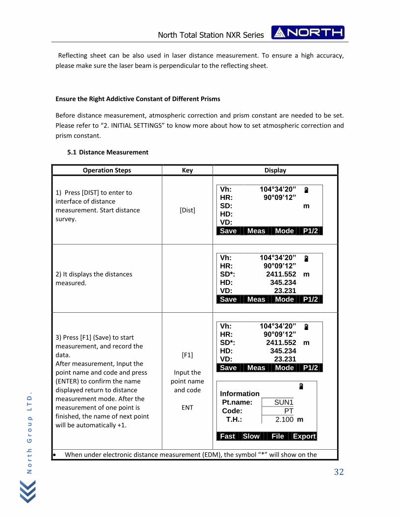
5.1 Distance Measurement
Operation Steps Key Display
1) Press [DIST] to enter to interface of distance measurement. Start distance survey.
[Dist]
Vh: 104°34’20” HR: 90°09’12” SD: m HD: VD:
Save Meas Mode P1/2
2) It displays the distances measured.
Vh: 104°34’20” HR: 90°09’12” SD*: 2411.552 m HD: 345.234 VD: 23.231
Save Meas Mode P1/2
3) Press [F1] (Save) to start measurement, and record the data. After measurement, Input the point name and code and press (ENTER) to confirm the name displayed return to distance measurement mode. After the measurement of one point is finished, the name of next point will be automatically +1.
[F1]
Input the point name
and code
ENT
Vh: 104°34’20” HR: 90°09’12” SD*: 2411.552 m HD: 345.234 VD: 23.231
Save Meas Mode P1/2
Information
Pt.name: SUN1
Code: PT
T.H.: 2.100 m
Fast Slow File Export
When under electronic distance measurement (EDM), the symbol “*” will show on the
North Total Station NXR Series
33
No
rt
h G
ro
up
LT
D.
screen
Units of distance: “m” (meter), “ft” (feet), “fi” (feet-inch).
If the measurement result is affected by atmospheric agitation, the instrument will repeat the survey operation automatically.
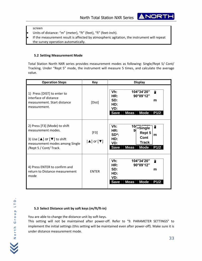
5.2 Setting Measurement Mode
Total Station North NXR series provides measurement modes as following: Single/Rept 5/ Cont/ Tracking. Under “Rept 5” mode, the instrument will measure 5 times, and calculate the average value.
Operation Steps Key Display
1) Press [DIST] to enter to interface of distance measurement. Start distance measurement.
[Dist]
Vh: 104°34’20” HR: 90°09’12” SD: m HD: VD:
Save Meas Mode P1/2
2) Press [F3] (Mode) to shift measurement modes. 3) Use [▲] or [▼] to shift measurement modes among Single /Rept 5 / Cont/ Track.
[F3]
[▲] or [▼]
Vh: 104°34’20” HR: 90°09’12” SD*: m HD: VD:
Save Meas Mode P1/2
4) Press ENTER to confirm and return to Distance measurement mode
ENTER
Vh: 104°34’20” HR: 90°09’12” SD: m HD: VD:
Save Meas Mode P1/2
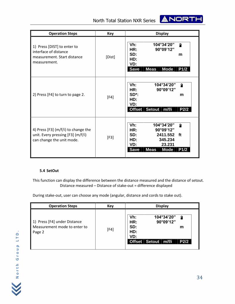
5.3 Select Distance unit by soft keys (m/ft/ft-in)
You are able to change the distance unit by soft keys. This setting will not be maintained after power‐off. Refer to “9. PARAMETER SETTINGS” to
implement the initial settings (this setting will be maintained even after power‐off). Make sure it is
under distance measurement mode.
>Single
Rept 5
Cont
Track
North Total Station NXR Series
34
No
rt
h G
ro
up
LT
D.
Operation Steps Key Display
1) Press [DIST] to enter to interface of distance measurement. Start distance measurement.
[Dist]
Vh: 104°34’20” HR: 90°09’12” SD: m HD: VD:
Save Meas Mode P1/2
2) Press [F4] to turn to page 2.
[F4]
Vh: 104°34’20” HR: 90°09’12” SD*: m HD: VD:
Offset Setout m/f/i P2/2
4) Press [F3] (m/f/i) to change the unit. Every pressing [F3] (m/f/i) can change the unit mode.
[F3]
Vh: 104°34’20” HR: 90°09’12” SD: 2411.552 ft HD: 345.234 VD: 23.231
Save Meas Mode P1/2
5.4 SetOut
This function can display the difference between the distance measured and the distance of setout. Distance measured – Distance of stake-out = difference displayed
During stake-out, user can choose any mode (angular, distance and cords to stake out).
Operation Steps Key Display
1) Press [F4] under Distance Measurement mode to enter to Page 2
[F4]
Vh: 104°34’20” HR: 90°09’12” SD: m HD: VD:
Offset Setout m/f/i P2/2
North Total Station NXR Series
35
No
rt
h G
ro
up
LT
D.
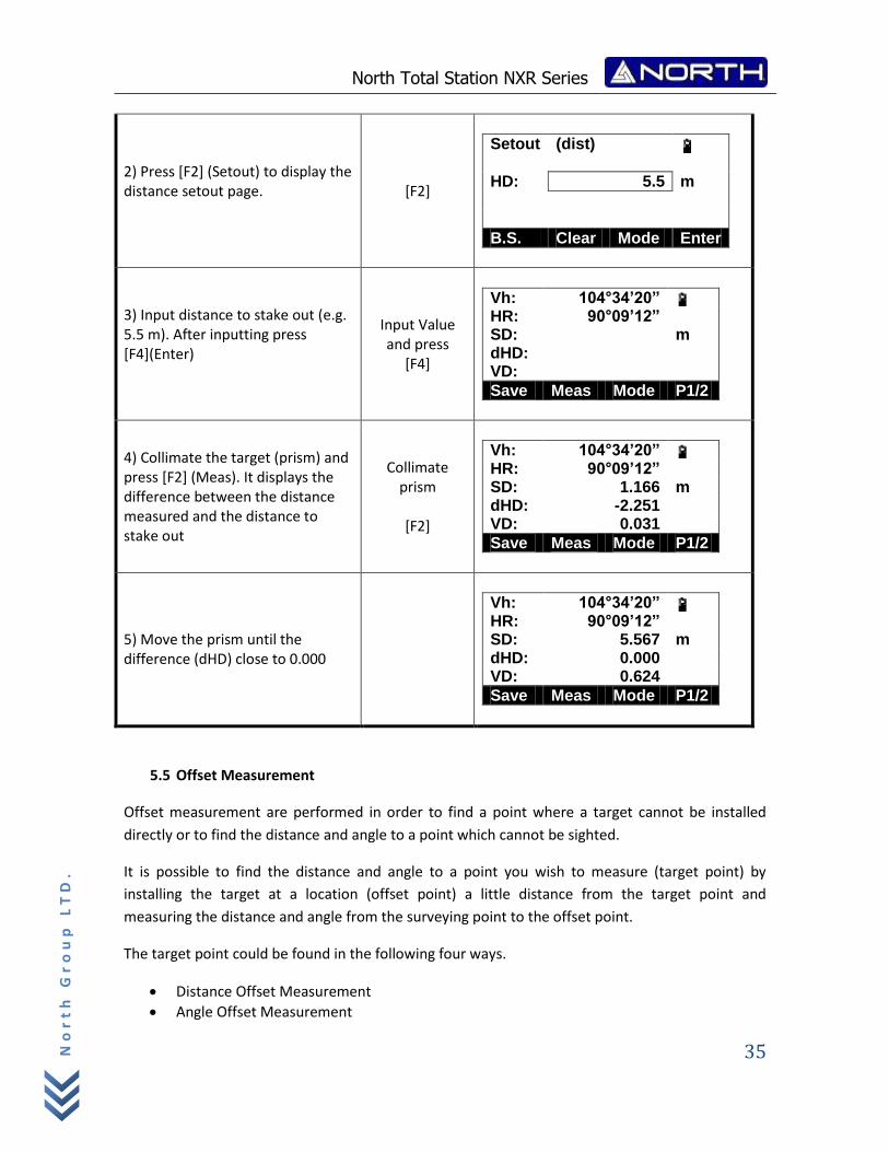
2) Press [F2] (Setout) to display the distance setout page.
[F2]
Setout (dist)
HD: 5.5 m
B.S. Clear Mode Enter
3) Input distance to stake out (e.g. 5.5 m). After inputting press [F4](Enter)
Input Value and press
[F4]
Vh: 104°34’20” HR: 90°09’12” SD: m dHD: VD:
Save Meas Mode P1/2
4) Collimate the target (prism) and press [F2] (Meas). It displays the difference between the distance measured and the distance to stake out
Collimate prism
[F2]
Vh: 104°34’20” HR: 90°09’12” SD: 1.166 m dHD: -2.251 VD: 0.031
Save Meas Mode P1/2
5) Move the prism until the difference (dHD) close to 0.000
Vh: 104°34’20” HR: 90°09’12” SD: 5.567 m dHD: 0.000 VD: 0.624
Save Meas Mode P1/2
5.5 Offset Measurement
Offset measurement are performed in order to find a point where a target cannot be installed
directly or to find the distance and angle to a point which cannot be sighted.
It is possible to find the distance and angle to a point you wish to measure (target point) by
installing the target at a location (offset point) a little distance from the target point and
measuring the distance and angle from the surveying point to the offset point.
The target point could be found in the following four ways.
Distance Offset Measurement
Angle Offset Measurement
North Total Station NXR Series
36
No
rt
h G
ro
up
LT
D.
Plane Offset Measurement
Column Offset Measurement
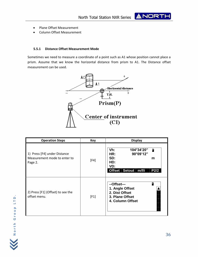
5.5.1 Distance Offset Measurement Mode
Sometimes we need to measure a coordinate of a point such as A1 whose position cannot place a
prism. Assume that we know the horizontal distance from prism to A1. The Distance offset
measurement can be used.
Operation Steps Key Display
1) Press [F4] under Distance Measurement mode to enter to Page 2.
[F4]
Vh: 104°34’20” HR: 90°09’12” SD: m HD: VD:
Offset Setout m/f/i P2/2
2) Press [F1] (Offset) to see the offset menu.
[F1]
--Offset—
1. Angle Offset ▲
2. Dist Offset 3. Plane Offset 4. Column Offset
North Total Station NXR Series
37
No
rt
h G
ro
up
LT
D.
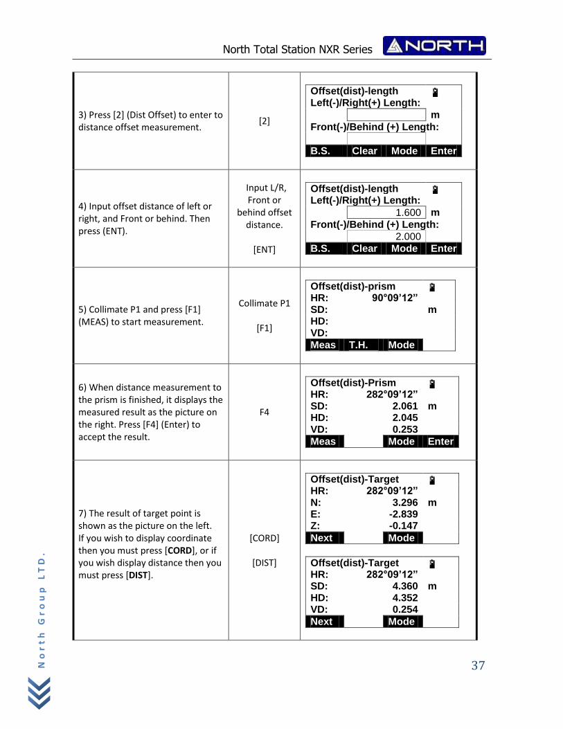
3) Press [2] (Dist Offset) to enter to distance offset measurement.
[2]
Offset(dist)-length Left(-)/Right(+) Length:
m
Front(-)/Behind (+) Length:
B.S. Clear Mode Enter
4) Input offset distance of left or right, and Front or behind. Then press (ENT).
Input L/R, Front or
behind offset distance.
[ENT]
Offset(dist)-length Left(-)/Right(+) Length:
1.600 m
Front(-)/Behind (+) Length:
2.000
B.S. Clear Mode Enter
5) Collimate P1 and press [F1] (MEAS) to start measurement.
Collimate P1
[F1]
Offset(dist)-prism HR: 90°09’12” SD: m HD: VD:
Meas T.H. Mode
6) When distance measurement to the prism is finished, it displays the measured result as the picture on the right. Press [F4] (Enter) to accept the result.
F4
Offset(dist)-Prism HR: 282°09’12” SD: 2.061 m HD: 2.045 VD: 0.253
Meas Mode Enter
7) The result of target point is shown as the picture on the left. If you wish to display coordinate then you must press [CORD], or if you wish display distance then you must press [DIST].
[CORD]
[DIST]
Offset(dist)-Target HR: 282°09’12” N: 3.296 m E: -2.839 Z: -0.147
Next Mode
Offset(dist)-Target HR: 282°09’12” SD: 4.360 m HD: 4.352 VD: 0.254
Next Mode
North Total Station NXR Series
38
No
rt
h G
ro
up
LT
D.
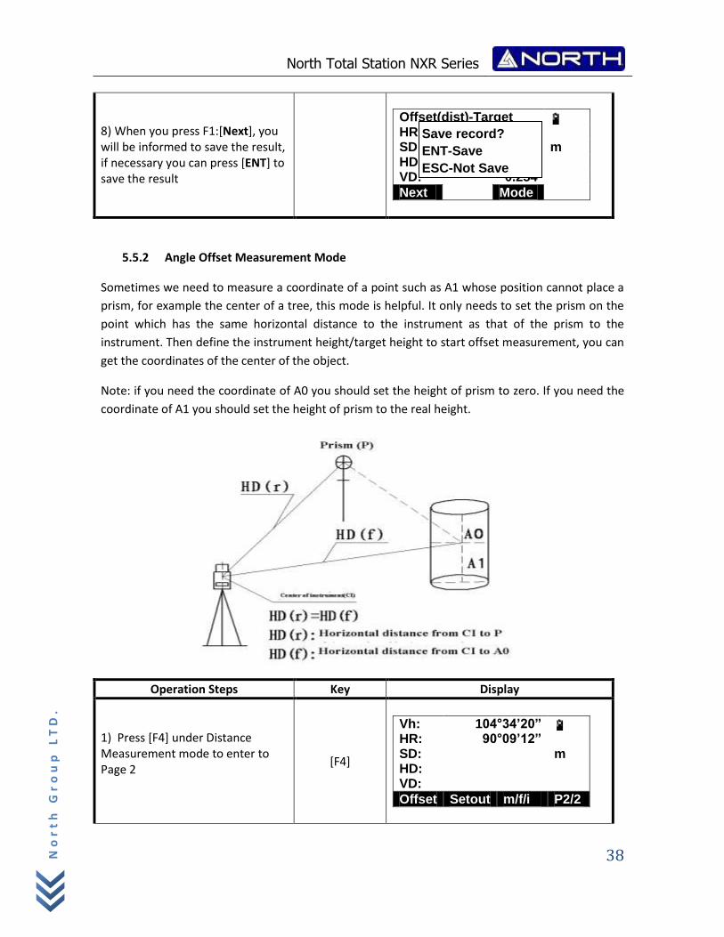
8) When you press F1:[Next], you will be informed to save the result, if necessary you can press [ENT] to save the result
Offset(dist)-Target HR: 282°09’12” SD: 4.360 m HD: 4.352 VD: 0.254
Next Mode
5.5.2 Angle Offset Measurement Mode
Sometimes we need to measure a coordinate of a point such as A1 whose position cannot place a
prism, for example the center of a tree, this mode is helpful. It only needs to set the prism on the
point which has the same horizontal distance to the instrument as that of the prism to the
instrument. Then define the instrument height/target height to start offset measurement, you can
get the coordinates of the center of the object.
Note: if you need the coordinate of A0 you should set the height of prism to zero. If you need the
coordinate of A1 you should set the height of prism to the real height.
Operation Steps Key Display
1) Press [F4] under Distance Measurement mode to enter to Page 2
[F4]
Vh: 104°34’20” HR: 90°09’12” SD: m HD: VD:
Offset Setout m/f/i P2/2
Save record?
ENT-Save
ESC-Not Save
North Total Station NXR Series
39
No
rt
h G
ro
up
LT
D.
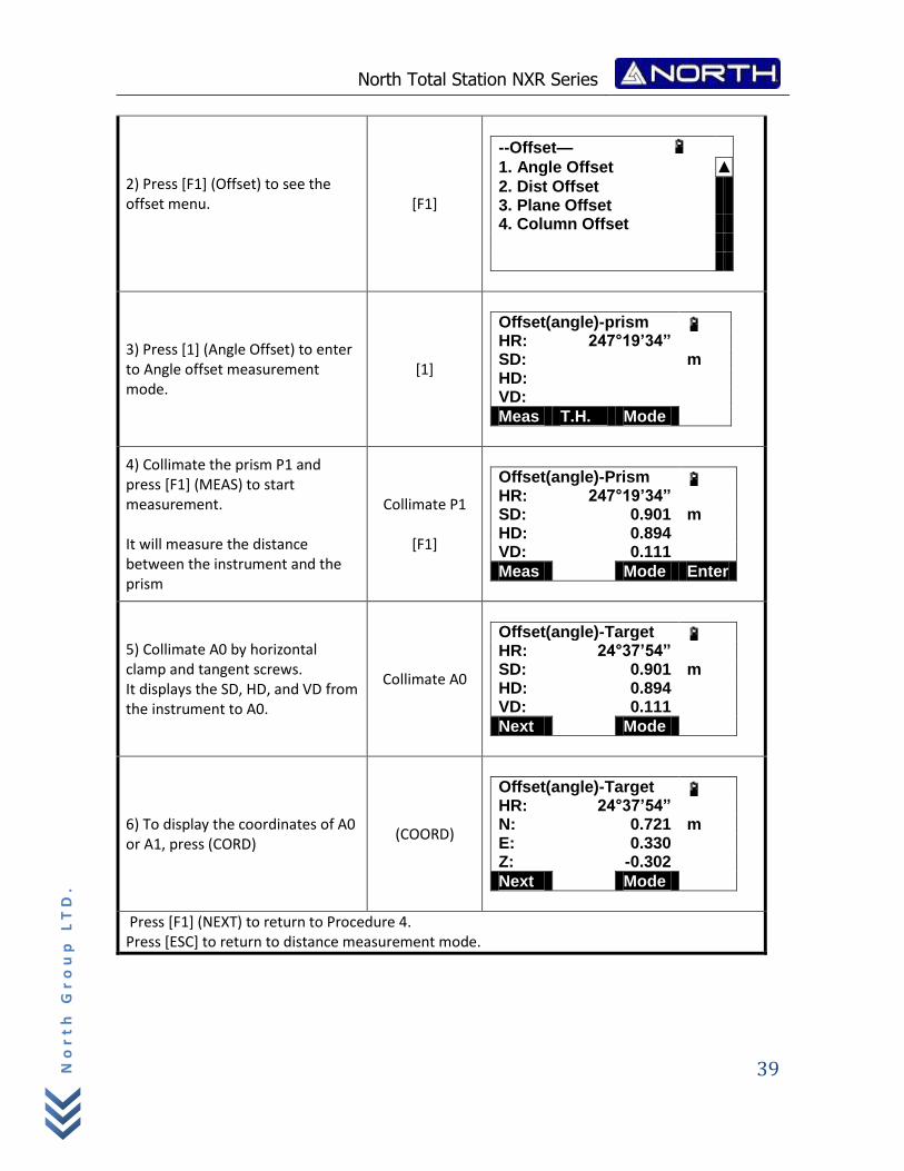
2) Press [F1] (Offset) to see the offset menu.
[F1]
--Offset—
1. Angle Offset ▲
2. Dist Offset 3. Plane Offset 4. Column Offset
3) Press [1] (Angle Offset) to enter to Angle offset measurement mode.
[1]
Offset(angle)-prism HR: 247°19’34” SD: m HD: VD:
Meas T.H. Mode
4) Collimate the prism P1 and press [F1] (MEAS) to start measurement. It will measure the distance between the instrument and the prism
Collimate P1
[F1]
Offset(angle)-Prism HR: 247°19’34” SD: 0.901 m HD: 0.894 VD: 0.111
Meas Mode Enter
5) Collimate A0 by horizontal clamp and tangent screws. It displays the SD, HD, and VD from the instrument to A0.
Collimate A0
Offset(angle)-Target HR: 24°37’54” SD: 0.901 m HD: 0.894 VD: 0.111
Next Mode
6) To display the coordinates of A0 or A1, press (CORD)
(COORD)
Offset(angle)-Target HR: 24°37’54” N: 0.721 m E: 0.330 Z: -0.302
Next Mode
Press [F1] (NEXT) to return to Procedure 4. Press [ESC] to return to distance measurement mode.
North Total Station NXR Series
40
No
rt
h G
ro
up
LT
D.
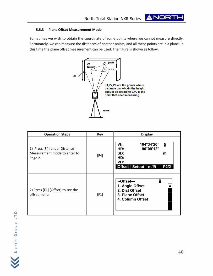
5.5.3 Plane Offset Measurement Mode
Sometimes we wish to obtain the coordinate of some points where we cannot measure directly.
Fortunately, we can measure the distances of another points, and all these points are in a plane. In
this time the plane offset measurement can be used. The figure is shown as follow.
Operation Steps Key Display
1) Press [F4] under Distance Measurement mode to enter to Page 2.
[F4]
Vh: 104°34’20” HR: 90°09’12” SD: m HD: VD:
Offset Setout m/f/i P2/2
2) Press [F1] (Offset) to see the offset menu.
[F1]
--Offset—
1. Angle Offset ▲
2. Dist Offset 3. Plane Offset 4. Column Offset
North Total Station NXR Series
41
No
rt
h G
ro
up
LT
D.
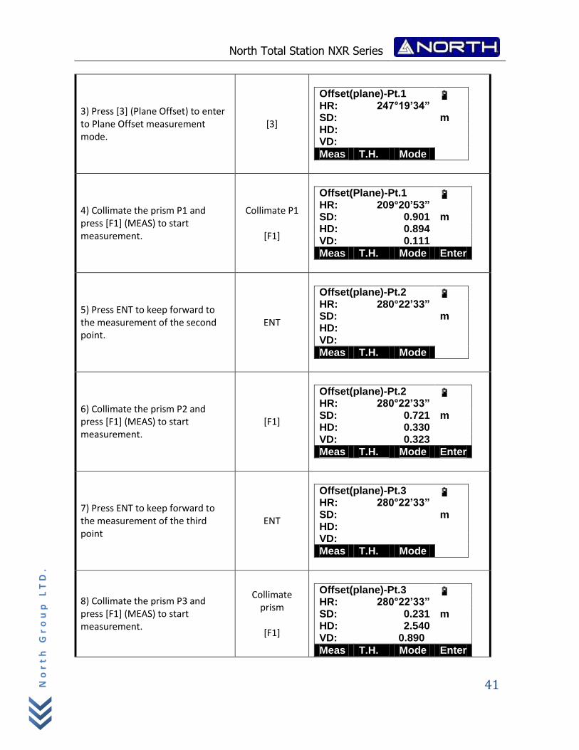
3) Press [3] (Plane Offset) to enter to Plane Offset measurement mode.
[3]
Offset(plane)-Pt.1 HR: 247°19’34” SD: m HD: VD:
Meas T.H. Mode
4) Collimate the prism P1 and press [F1] (MEAS) to start measurement.
Collimate P1
[F1]
Offset(Plane)-Pt.1 HR: 209°20’53” SD: 0.901 m HD: 0.894 VD: 0.111
Meas T.H. Mode Enter
5) Press ENT to keep forward to the measurement of the second point.
ENT
Offset(plane)-Pt.2 HR: 280°22’33” SD: m HD: VD:
Meas T.H. Mode
6) Collimate the prism P2 and press [F1] (MEAS) to start measurement.
[F1]
Offset(plane)-Pt.2 HR: 280°22’33” SD: 0.721 m HD: 0.330 VD: 0.323
Meas T.H. Mode Enter
7) Press ENT to keep forward to the measurement of the third point
ENT
Offset(plane)-Pt.3 HR: 280°22’33” SD: m HD: VD:
Meas T.H. Mode
8) Collimate the prism P3 and press [F1] (MEAS) to start measurement.
Collimate prism
[F1]
Offset(plane)-Pt.3 HR: 280°22’33” SD: 0.231 m HD: 2.540 VD: 0.890
Meas T.H. Mode Enter
North Total Station NXR Series
42
No
rt
h G
ro
up
LT
D.
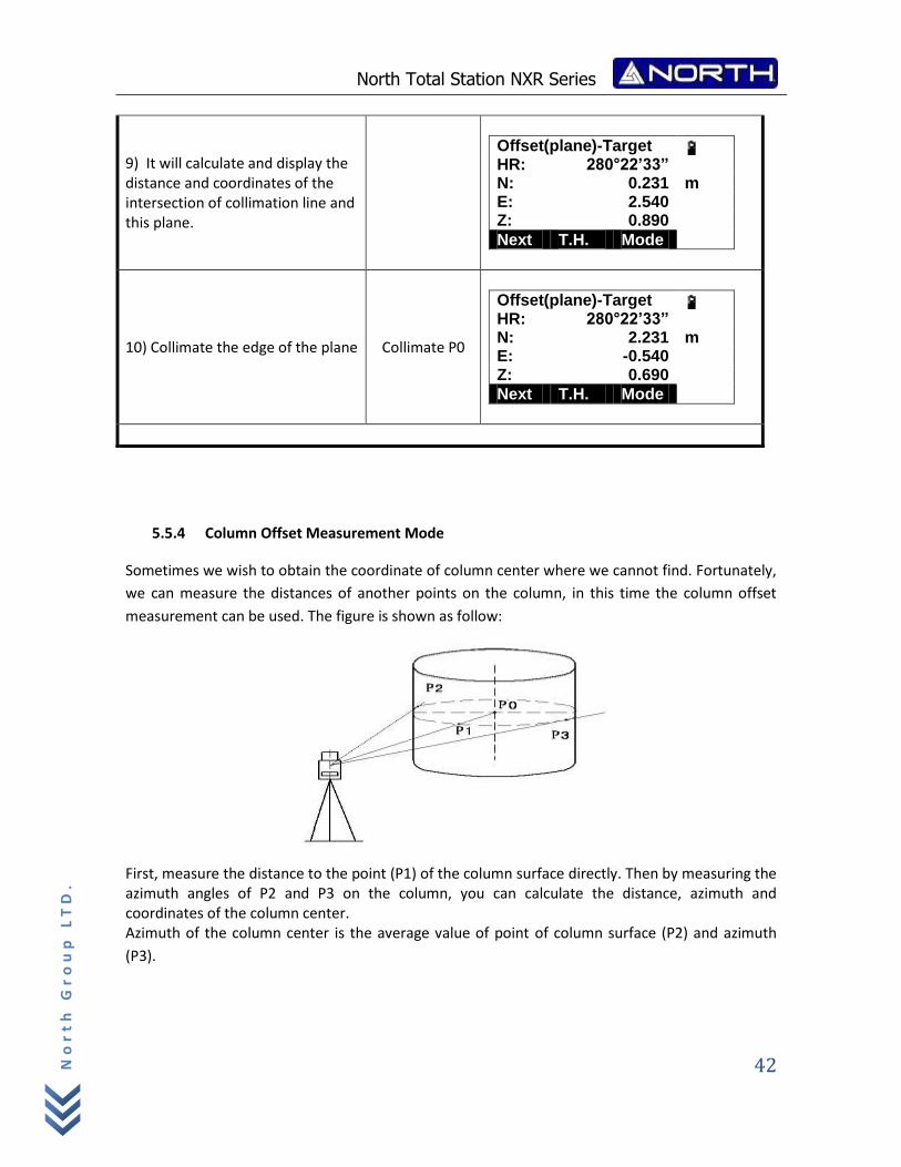
9) It will calculate and display the distance and coordinates of the intersection of collimation line and this plane.
Offset(plane)-Target HR: 280°22’33” N: 0.231 m E: 2.540 Z: 0.890
Next T.H. Mode
10) Collimate the edge of the plane Collimate P0
Offset(plane)-Target HR: 280°22’33” N: 2.231 m E: -0.540 Z: 0.690
Next T.H. Mode
5.5.4 Column Offset Measurement Mode
Sometimes we wish to obtain the coordinate of column center where we cannot find. Fortunately,
we can measure the distances of another points on the column, in this time the column offset
measurement can be used. The figure is shown as follow:
First, measure the distance to the point (P1) of the column surface directly. Then by measuring the azimuth angles of P2 and P3 on the column, you can calculate the distance, azimuth and coordinates of the column center. Azimuth of the column center is the average value of point of column surface (P2) and azimuth
(P3).
North Total Station NXR Series
43
No
rt
h G
ro
up
LT
D.
Operation Steps Key Display
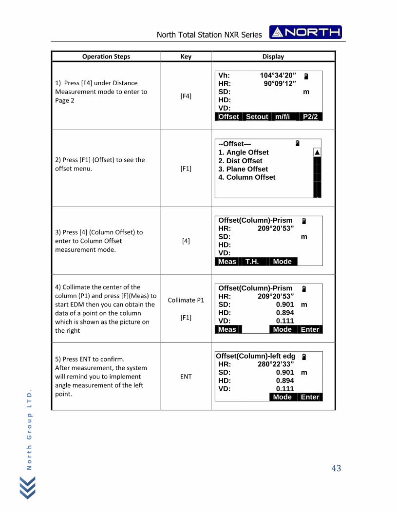
1) Press [F4] under Distance Measurement mode to enter to Page 2
[F4]
Vh: 104°34’20” HR: 90°09’12” SD: m HD: VD:
Offset Setout m/f/i P2/2
2) Press [F1] (Offset) to see the offset menu.
[F1]
--Offset—
1. Angle Offset ▲
2. Dist Offset 3. Plane Offset 4. Column Offset
3) Press [4] (Column Offset) to enter to Column Offset measurement mode.
[4]
Offset(Column)-Prism HR: 209°20’53” SD: m HD: VD:
Meas T.H. Mode
4) Collimate the center of the column (P1) and press [F](Meas) to start EDM then you can obtain the data of a point on the column which is shown as the picture on the right
Collimate P1
[F1]
Offset(Column)-Prism HR: 209°20’53” SD: 0.901 m HD: 0.894 VD: 0.111
Meas Mode Enter
5) Press ENT to confirm. After measurement, the system will remind you to implement angle measurement of the left point.
ENT
Offset(Column)-left edg HR: 280°22’33” SD: 0.901 m HD: 0.894 VD: 0.111 Mode Enter
North Total Station NXR Series
44
No
rt
h G
ro
up
LT
D.
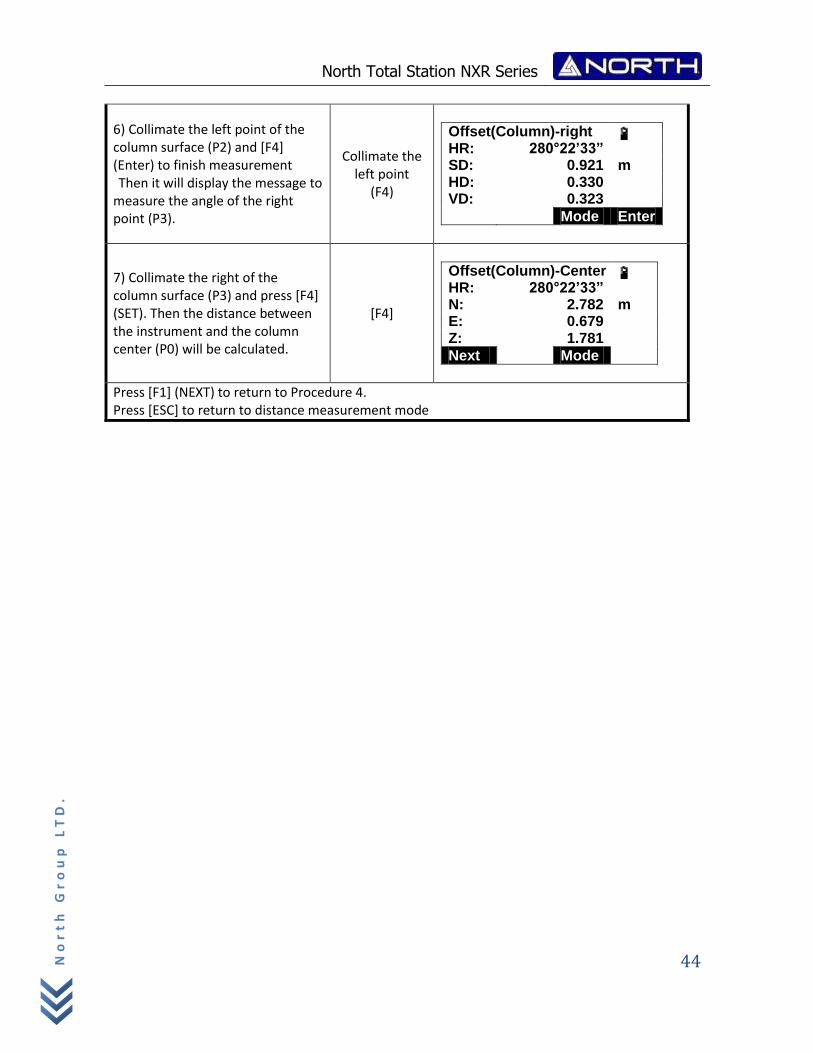
6) Collimate the left point of the column surface (P2) and [F4] (Enter) to finish measurement Then it will display the message to
measure the angle of the right point (P3).
Collimate the left point
(F4)
Offset(Column)-right HR: 280°22’33” SD: 0.921 m HD: 0.330 VD: 0.323
Mode Enter
7) Collimate the right of the column surface (P3) and press [F4] (SET). Then the distance between the instrument and the column center (P0) will be calculated.
[F4]
Offset(Column)-Center HR: 280°22’33” N: 2.782 m E: 0.679 Z: 1.781
Next Mode
Press [F1] (NEXT) to return to Procedure 4. Press [ESC] to return to distance measurement mode
North Total Station NXR Series
45
No
rt
h G
ro
up
LT
D.
6. COORDINATES MEASUREMENT
It is possible to find the 3D coordinates of a target by coordinate measurement. Please input the
station coordinate, instrument height, target height, backsight coordinate (or azimuth angle) and
azimuth before coordinate measurement.
When measuring the coordinates after inputting the instrument height and target height, you can
measure the unknown coordinates directly.
To define the coordinates of occupied point, refer to “6.1 SETTING COORDINATES OF
OCCUPIED POINT”.
To define the instrument height and target height, refer to “6.2 SETTING INSTRUMENT
HEIGHT” and “6.3 SETTING TARGET HEIGHT”.
To measure the coordinates, you should define the backsight point and measure the
azimuth of backsight point first.
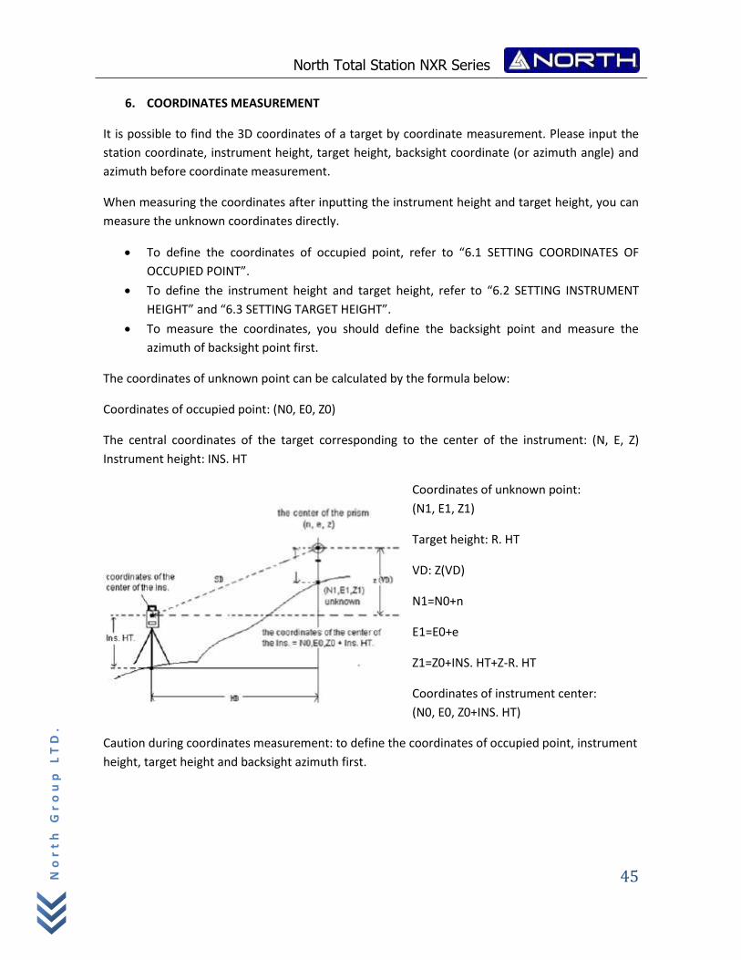
The coordinates of unknown point can be calculated by the formula below:
Coordinates of occupied point: (N0, E0, Z0)
The central coordinates of the target corresponding to the center of the instrument: (N, E, Z)
Instrument height: INS. HT
Coordinates of unknown point:
(N1, E1, Z1)
Target height: R. HT
VD: Z(VD)
N1=N0+n
E1=E0+e
Z1=Z0+INS. HT+Z‐R. HT
Coordinates of instrument center:
(N0, E0, Z0+INS. HT)
Caution during coordinates measurement: to define the coordinates of occupied point, instrument
height, target height and backsight azimuth first.
North Total Station NXR Series
46
No
rt
h G
ro
up
LT
D.
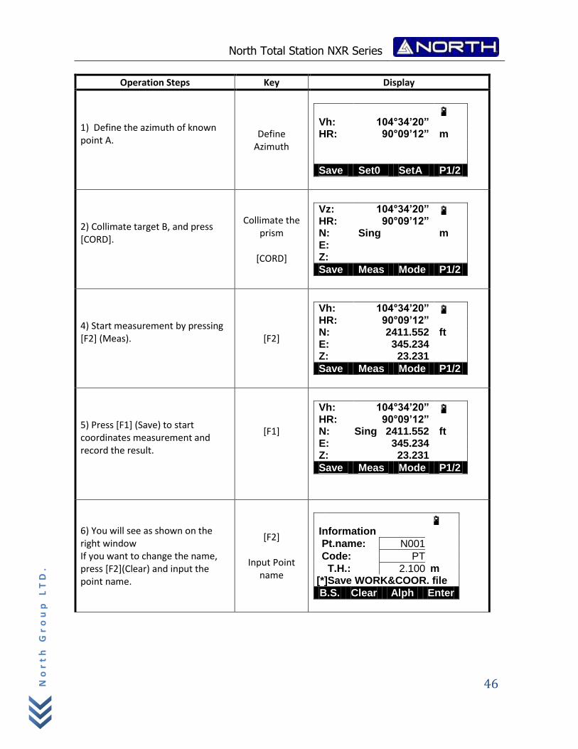
Operation Steps Key Display
1) Define the azimuth of known point A.
Define Azimuth
Vh: 104°34’20” HR: 90°09’12” m
Save Set0 SetA P1/2
2) Collimate target B, and press [CORD].
Collimate the prism
[CORD]
Vz: 104°34’20” HR: 90°09’12” N: Sing m E: Z:
Save Meas Mode P1/2
4) Start measurement by pressing [F2] (Meas).
[F2]
Vh: 104°34’20” HR: 90°09’12” N: 2411.552 ft E: 345.234 Z: 23.231
Save Meas Mode P1/2
5) Press [F1] (Save) to start coordinates measurement and record the result.
[F1]
Vh: 104°34’20” HR: 90°09’12” N: Sing 2411.552 ft E: 345.234 Z: 23.231
Save Meas Mode P1/2
6) You will see as shown on the right window If you want to change the name, press [F2](Clear) and input the point name.
[F2]
Input Point name
Information
Pt.name: N001
Code: PT
T.H.: 2.100 m [*]Save WORK&COOR. file
B.S. Clear Alph Enter
North Total Station NXR Series
47
No
rt
h G
ro
up
LT
D.
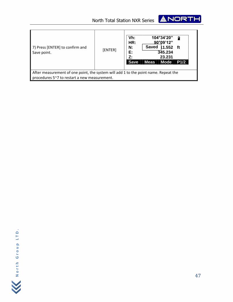
7) Press [ENTER] to confirm and Save point.
[ENTER]
Vh: 104°34’20” HR: 90°09’12” N: Sing 2411.552 ft E: 345.234 Z: 23.231
Save Meas Mode P1/2
After measurement of one point, the system will add 1 to the point name. Repeat the procedures 5~7 to restart a new measurement.
Saved
North Total Station NXR Series
48
No
rt
h G
ro
up
LT
D.
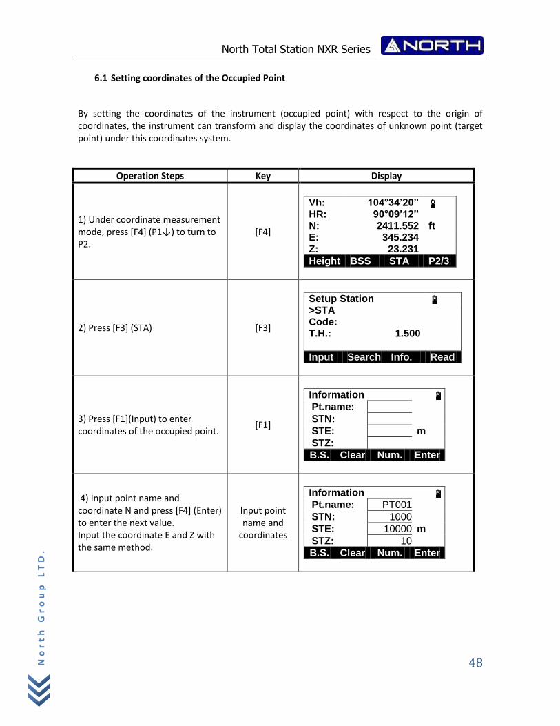
6.1 Setting coordinates of the Occupied Point
By setting the coordinates of the instrument (occupied point) with respect to the origin of coordinates, the instrument can transform and display the coordinates of unknown point (target point) under this coordinates system.
Operation Steps Key Display
1) Under coordinate measurement mode, press [F4] (P1↓) to turn to P2.
[F4]
Vh: 104°34’20” HR: 90°09’12” N: 2411.552 ft E: 345.234 Z: 23.231
Height BSS STA P2/3
2) Press [F3] (STA) [F3]
Setup Station >STA Code: T.H.: 1.500
Input Search Info. Read
3) Press [F1](Input) to enter coordinates of the occupied point.
[F1]
Information Pt.name:
STN:
STE: m
STZ:
B.S. Clear Num. Enter
4) Input point name and coordinate N and press [F4] (Enter) to enter the next value. Input the coordinate E and Z with the same method.
Input point name and
coordinates
Information Pt.name: PT001
STN: 1000
STE: 10000 m
STZ: 10
B.S. Clear Num. Enter
North Total Station NXR Series
49
No
rt
h G
ro
up
LT
D.
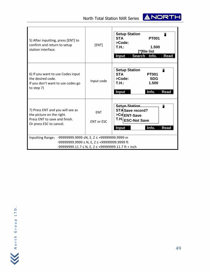
5) After inputting, press [ENT] to confirm and return to setup station interface.
[ENT]
Setup Station STA PT001 >Code: T.H.: 1.500 [*]file list
Input Search Info. Read
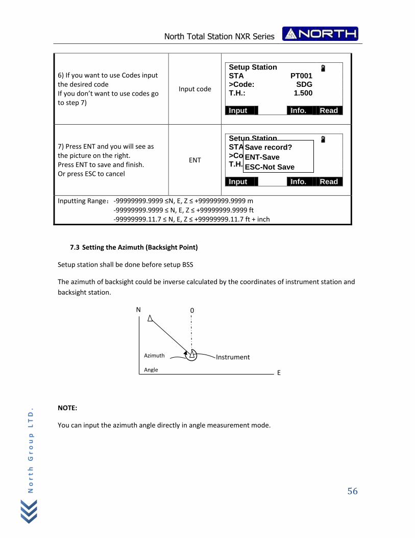
6) If you want to use Codes input the desired code. If you don’t want to use codes go to step 7)
Input code
Setup Station STA PT001 >Code: SDG T.H.: 1.500
Input Info. Read
7) Press ENT and you will see as the picture on the right. Press ENT to save and finish. Or press ESC to cancel.
ENT
ENT or ESC
Setup Station STA PT001 >Code: SDG T.H.: 1.500
Input Info. Read
Inputting Range:‐99999999.9999 ≤N, E, Z ≤ +99999999.9999 m ‐99999999.9999 ≤ N, E, Z ≤ +99999999.9999 ft ‐99999999.11.7 ≤ N, E, Z ≤ +99999999.11.7 ft + inch
Save record?
ENT-Save
ESC-Not Save
North Total Station NXR Series
50
No
rt
h G
ro
up
LT
D.
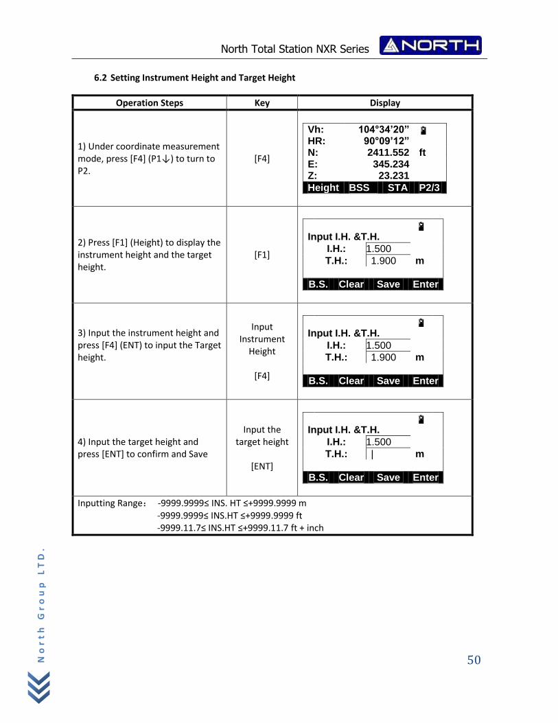
6.2 Setting Instrument Height and Target Height
Operation Steps Key Display
1) Under coordinate measurement mode, press [F4] (P1↓) to turn to P2.
[F4]
Vh: 104°34’20” HR: 90°09’12” N: 2411.552 ft E: 345.234 Z: 23.231
Height BSS STA P2/3
2) Press [F1] (Height) to display the instrument height and the target height.
[F1]
Input I.H. &T.H.
I.H.: 1.500
T.H.: 1.900 m
B.S. Clear Save Enter
3) Input the instrument height and press [F4] (ENT) to input the Target height.
Input Instrument
Height
[F4]
Input I.H. &T.H.
I.H.: 1.500
T.H.: 1.900 m
B.S. Clear Save Enter
4) Input the target height and press [ENT] to confirm and Save
Input the target height
[ENT]
Input I.H. &T.H.
I.H.: 1.500
T.H.: | m
B.S. Clear Save Enter
Inputting Range: ‐9999.9999≤ INS. HT ≤+9999.9999 m ‐9999.9999≤ INS.HT ≤+9999.9999 ft ‐9999.11.7≤ INS.HT ≤+9999.11.7 ft + inch
North Total Station NXR Series
51
No
rt
h G
ro
up
LT
D.
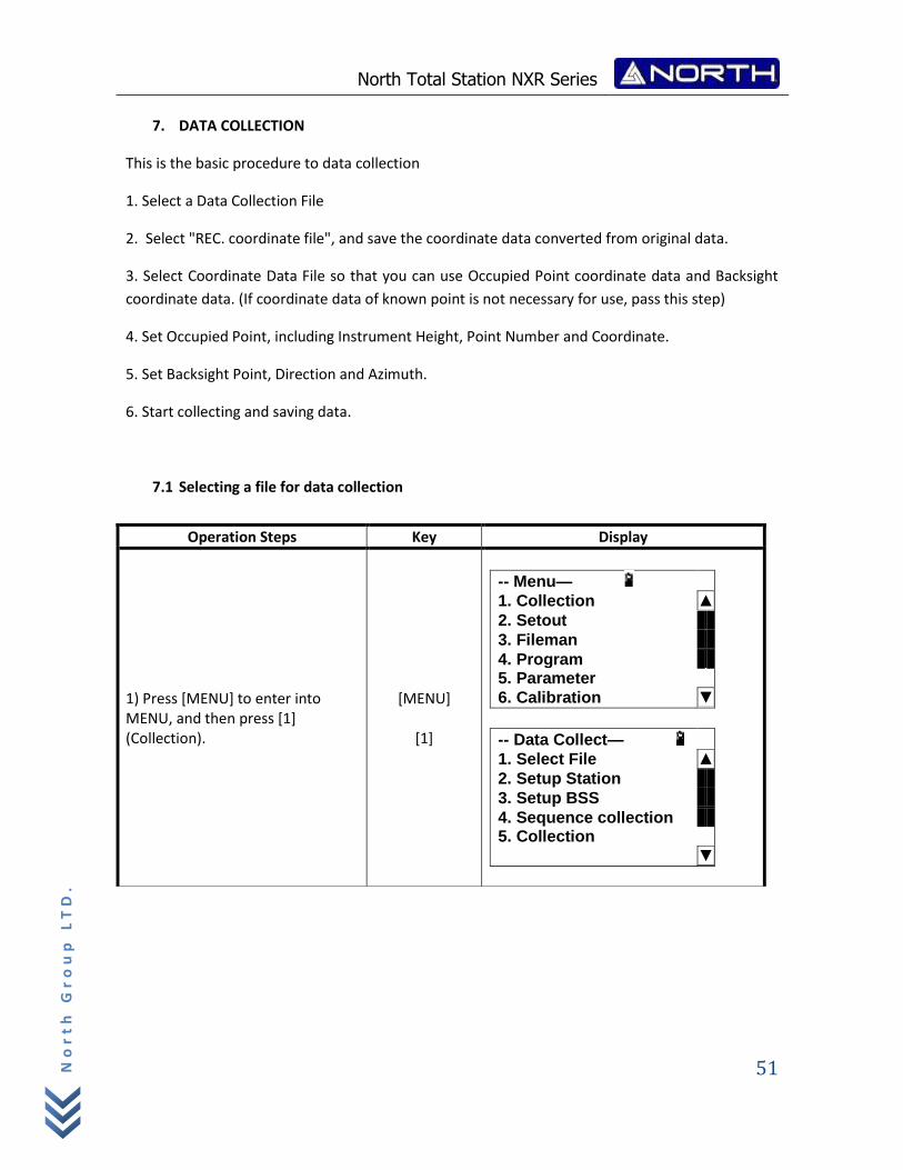
7. DATA COLLECTION
This is the basic procedure to data collection
1. Select a Data Collection File
2. Select "REC. coordinate file", and save the coordinate data converted from original data.
3. Select Coordinate Data File so that you can use Occupied Point coordinate data and Backsight
coordinate data. (If coordinate data of known point is not necessary for use, pass this step)
4. Set Occupied Point, including Instrument Height, Point Number and Coordinate.
5. Set Backsight Point, Direction and Azimuth.
6. Start collecting and saving data.
7.1 Selecting a file for data collection
Operation Steps Key Display
1) Press [MENU] to enter into MENU, and then press [1] (Collection).
[MENU]
[1]
-- Menu—
1. Collection ▲
2. Setout
3. Fileman
4. Program 5. Parameter
6. Calibration ▼
-- Data Collect—
1. Select File ▲
2. Setup Station
3. Setup BSS
4. Sequence collection 5. Collection
▼
North Total Station NXR Series
52
No
rt
h G
ro
up
LT
D.
7.2 Setup Station
The occupied point and direction angle in the data collect mode are linked with the occupied point and it is possible to set or change the occupied point and direction angle from the data collect mode.
Occupied point can be set by two setting methods as follow:
1) Setting from the coordinate data stored in the internal memory 2) Direct key input
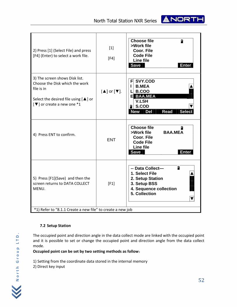
2) Press [1] (Select File) and press [F4] (Enter) to select a work file.
[1]
[F4]
Choose file >Work file Coor. File Code File Line file Save Enter
3) The screen shows Disk list. Choose the Disk which the work file is in Select the desired file using [▲] or [▼] or create a new one *1
[▲] or [▼].
F SVY.COD I B.MEA ▲
L B.COO E BAA.MEA V.LSH
S.COD ▼
New Del Read Select
4) Press ENT to confirm.
ENT
Choose file >Work file BAA.MEA Coor. File Code File Line file Save Enter
5) Press [F1](Save) and then the screen returns to DATA COLLECT MENU.
[F1]
-- Data Collect—
1. Select File ▲
2. Setup Station
3. Setup BSS
4. Sequence collection 5. Collection
▼
*1) Refer to “8.1.1 Create a new file” to create a new job
North Total Station NXR Series
53
No
rt
h G
ro
up
LT
D.
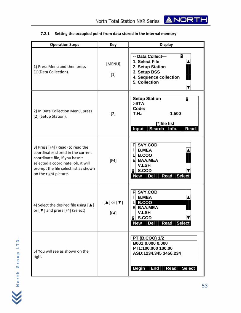
7.2.1 Setting the occupied point from data stored in the internal memory
Operation Steps Key Display
1) Press Menu and then press [1](Data Collection).
[MENU]
[1]
-- Data Collect—
1. Select File ▲
2. Setup Station
3. Setup BSS
4. Sequence collection 5. Collection
▼
2) In Data Collection Menu, press [2] (Setup Station).
[2]
Setup Station >STA Code: T.H.: 1.500
[*]file list
Input Search Info. Read
3) Press [F4] (Read) to read the coordinates stored in the current coordinate file, if you hasn’t selected a coordinate job, it will prompt the file select list as shown on the right picture.
[F4]
F SVY.COD I B.MEA ▲
L B.COO E BAA.MEA V.LSH
S.COD ▼
New Del Read Select
4) Select the desired file using [▲] or [▼] and press [F4] (Select)
[▲] or [▼]
[F4]
F SVY.COD I B.MEA ▲
L B.COO E BAA.MEA V.LSH
S.COD ▼
New Del Read Select
5) You will see as shown on the right
PT.(B.COO) 1/2
B001:0.000 0.000 PT1:100.000 100.00 ASD:1234.345 3456.234 Begin End Read Select
North Total Station NXR Series
54
No
rt
h G
ro
up
LT
D.
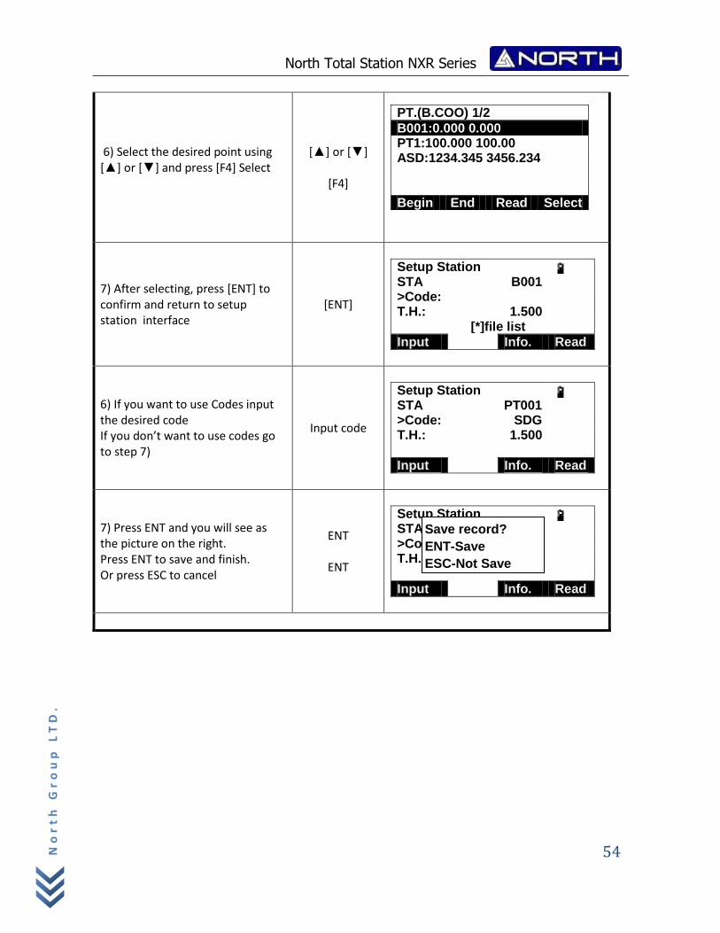
6) Select the desired point using [▲] or [▼] and press [F4] Select
[▲] or [▼]
[F4]
PT.(B.COO) 1/2
B001:0.000 0.000 PT1:100.000 100.00 ASD:1234.345 3456.234 Begin End Read Select
7) After selecting, press [ENT] to confirm and return to setup station interface
[ENT]
Setup Station STA B001 >Code: T.H.: 1.500 [*]file list
Input Info. Read
6) If you want to use Codes input the desired code If you don’t want to use codes go to step 7)
Input code
Setup Station STA PT001 >Code: SDG T.H.: 1.500
Input Info. Read
7) Press ENT and you will see as the picture on the right. Press ENT to save and finish. Or press ESC to cancel
ENT
ENT
Setup Station STA PT001 >Code: SDG T.H.: 1.500
Input Info. Read
Save record?
ENT-Save
ESC-Not Save
North Total Station NXR Series
55
No
rt
h G
ro
up
LT
D.
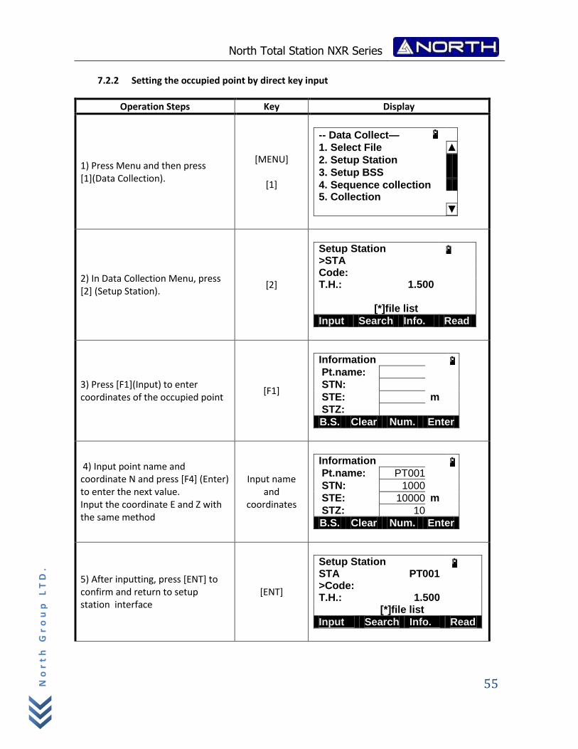
7.2.2 Setting the occupied point by direct key input
Operation Steps Key Display
1) Press Menu and then press [1](Data Collection).
[MENU]
[1]
-- Data Collect—
1. Select File ▲
2. Setup Station
3. Setup BSS
4. Sequence collection 5. Collection
▼
2) In Data Collection Menu, press [2] (Setup Station).
[2]
Setup Station >STA Code: T.H.: 1.500
[*]file list
Input Search Info. Read
3) Press [F1](Input) to enter coordinates of the occupied point
[F1]
Information Pt.name:
STN:
STE: m
STZ:
B.S. Clear Num. Enter
4) Input point name and coordinate N and press [F4] (Enter) to enter the next value. Input the coordinate E and Z with the same method
Input name and
coordinates
Information Pt.name: PT001
STN: 1000
STE: 10000 m
STZ: 10
B.S. Clear Num. Enter
5) After inputting, press [ENT] to confirm and return to setup station interface
[ENT]
Setup Station STA PT001 >Code: T.H.: 1.500 [*]file list
Input Search Info. Read
North Total Station NXR Series
56
No
rt
h G
ro
up
LT
D.
6) If you want to use Codes input the desired code If you don’t want to use codes go to step 7)
Input code
Setup Station STA PT001 >Code: SDG T.H.: 1.500
Input Info. Read
7) Press ENT and you will see as the picture on the right. Press ENT to save and finish. Or press ESC to cancel
ENT
Setup Station STA PT001 >Code: SDG T.H.: 1.500
Input Info. Read
Inputting Range:‐99999999.9999 ≤N, E, Z ≤ +99999999.9999 m ‐99999999.9999 ≤ N, E, Z ≤ +99999999.9999 ft ‐99999999.11.7 ≤ N, E, Z ≤ +99999999.11.7 ft + inch
7.3 Setting the Azimuth (Backsight Point)
Setup station shall be done before setup BSS
The azimuth of backsight could be inverse calculated by the coordinates of instrument station and
backsight station.
NOTE:
You can input the azimuth angle directly in angle measurement mode.
0 N
Azimuth
Angle
Instrument
Station E
Save record?
ENT-Save
ESC-Not Save
North Total Station NXR Series
57
No
rt
h G
ro
up
LT
D.
7.3.1 Setting the Backsight point from data stored in the internal memory
Operation Steps Key Display
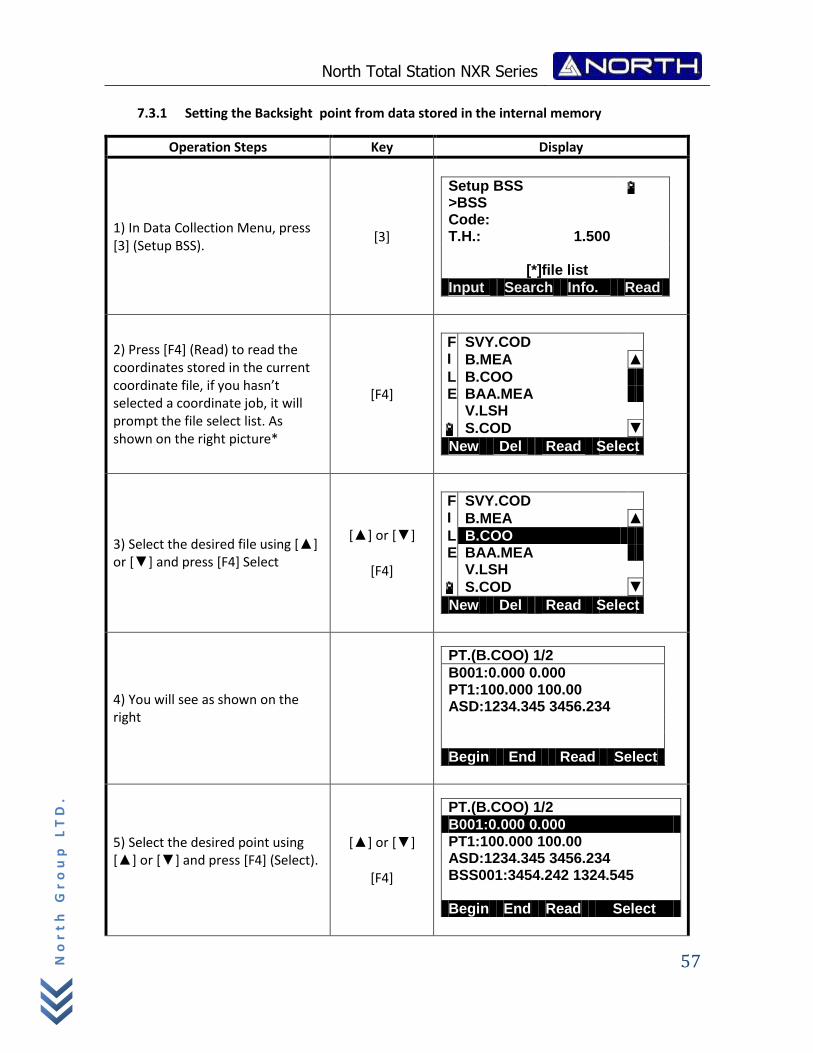
1) In Data Collection Menu, press [3] (Setup BSS).
[3]
Setup BSS >BSS Code: T.H.: 1.500
[*]file list
Input Search Info. Read
2) Press [F4] (Read) to read the coordinates stored in the current coordinate file, if you hasn’t selected a coordinate job, it will prompt the file select list. As shown on the right picture*
[F4]
F SVY.COD I B.MEA ▲
L B.COO E BAA.MEA V.LSH
S.COD ▼
New Del Read Select
3) Select the desired file using [▲] or [▼] and press [F4] Select
[▲] or [▼]
[F4]
F SVY.COD I B.MEA ▲
L B.COO E BAA.MEA V.LSH
S.COD ▼
New Del Read Select
4) You will see as shown on the right
PT.(B.COO) 1/2
B001:0.000 0.000 PT1:100.000 100.00 ASD:1234.345 3456.234 Begin End Read Select
5) Select the desired point using [▲] or [▼] and press [F4] (Select).
[▲] or [▼]
[F4]
PT.(B.COO) 1/2
B001:0.000 0.000 PT1:100.000 100.00 ASD:1234.345 3456.234 BSS001:3454.242 1324.545 Begin End Read Select
North Total Station NXR Series
58
No
rt
h G
ro
up
LT
D.
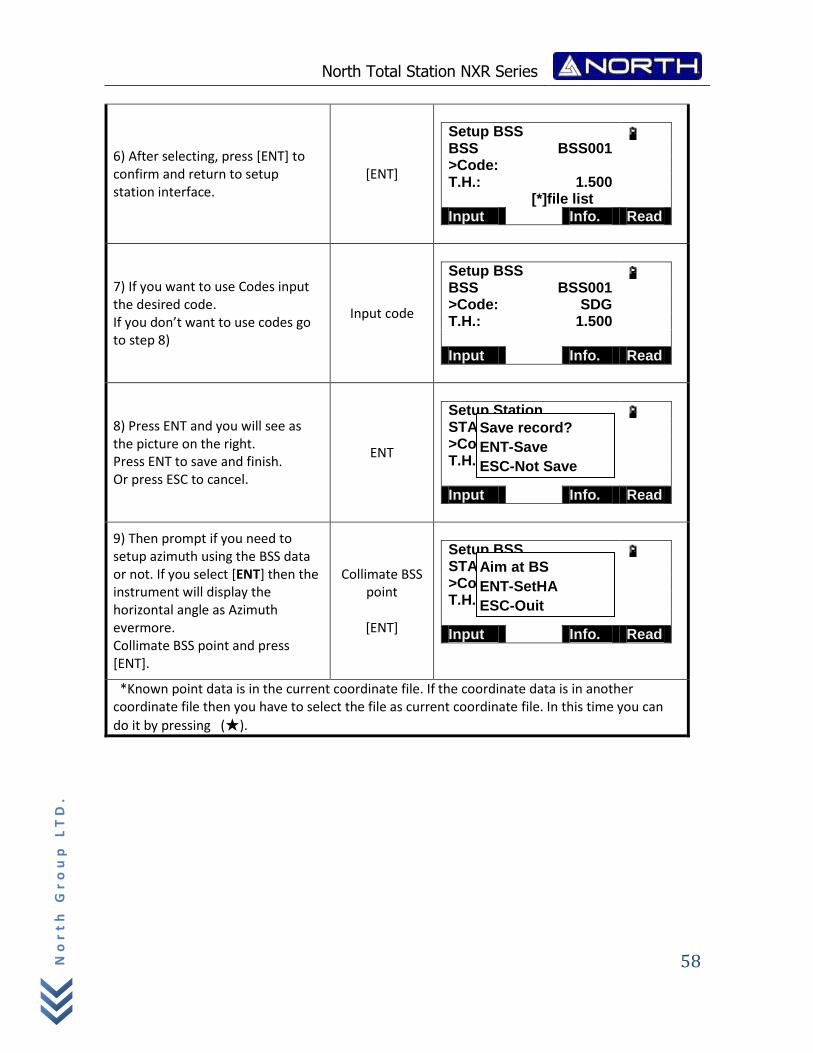
6) After selecting, press [ENT] to confirm and return to setup station interface.
[ENT]
Setup BSS BSS BSS001 >Code: T.H.: 1.500 [*]file list
Input Info. Read
7) If you want to use Codes input the desired code. If you don’t want to use codes go to step 8)
Input code
Setup BSS BSS BSS001 >Code: SDG T.H.: 1.500
Input Info. Read
8) Press ENT and you will see as the picture on the right. Press ENT to save and finish. Or press ESC to cancel.
ENT
Setup Station STA PT001 >Code: SDG T.H.: 1.500
Input Info. Read
9) Then prompt if you need to setup azimuth using the BSS data or not. If you select [ENT] then the instrument will display the horizontal angle as Azimuth evermore. Collimate BSS point and press [ENT].
Collimate BSS point
[ENT]
Setup BSS STA PT001 >Code: SDG T.H.: 1.500
Input Info. Read
*Known point data is in the current coordinate file. If the coordinate data is in another coordinate file then you have to select the file as current coordinate file. In this time you can
do it by pressing (★).
Save record?
ENT-Save
ESC-Not Save
Aim at BS
ENT-SetHA
ESC-Quit
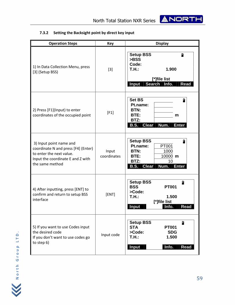
North Total Station NXR Series
59
No
rt
h G
ro
up
LT
D.
7.3.2 Setting the Backsight point by direct key input
Operation Steps Key Display
1) In Data Collection Menu, press [3] (Setup BSS)
[3]
Setup BSS >BSS Code: T.H.: 1.900
[*]file list
Input Search Info. Read
2) Press [F1](Input) to enter coordinates of the occupied point
[F1]
Set BS Pt.name:
BTN:
BTE: m
BTZ:
B.S. Clear Num. Enter
3) Input point name and coordinate N and press [F4] (Enter) to enter the next value. Input the coordinate E and Z with the same method
Input coordinates
Setup BSS Pt.name: PT001
BTN: 1000
BTE: 10000 m
BTZ: 10
B.S. Clear Num. Enter
4) After inputting, press [ENT] to confirm and return to setup BSS interface
[ENT]
Setup BSS BSS PT001 >Code: T.H.: 1.500 [*]file list
Input Info. Read
5) If you want to use Codes input the desired code If you don’t want to use codes go to step 6)
Input code
Setup BSS STA PT001 >Code: SDG T.H.: 1.500
Input Info. Read
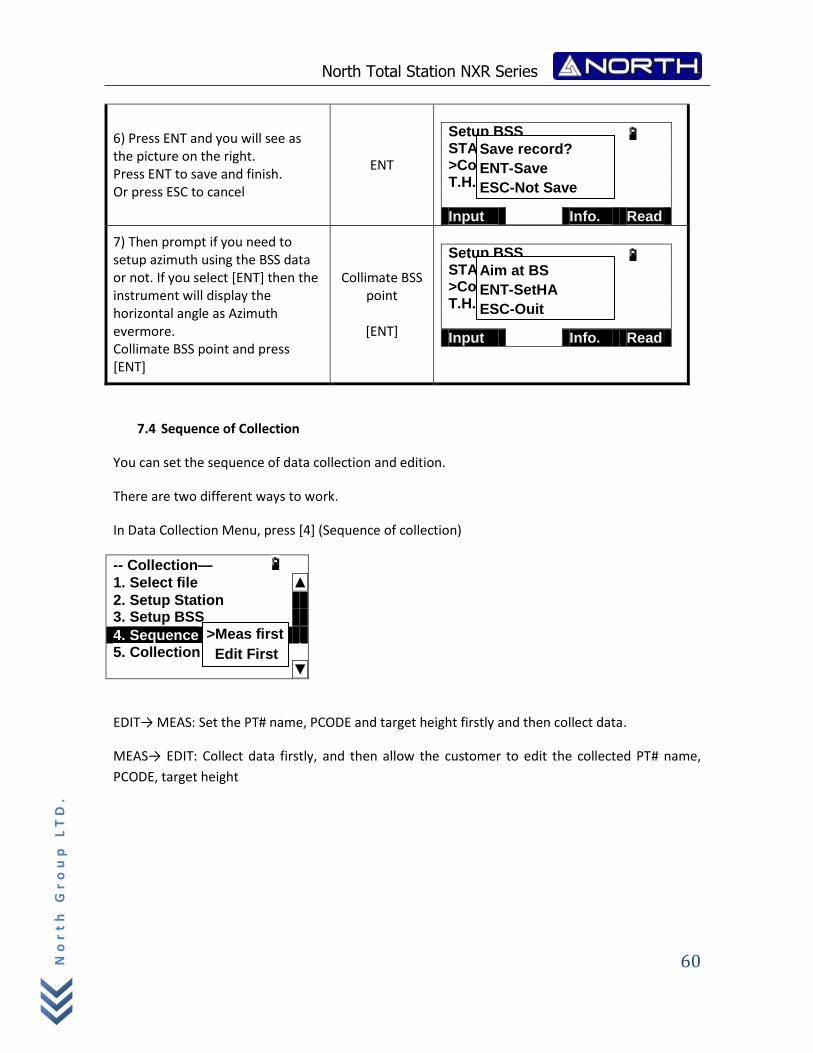
North Total Station NXR Series
60
No
rt
h G
ro
up
LT
D.
6) Press ENT and you will see as the picture on the right. Press ENT to save and finish. Or press ESC to cancel
ENT
Setup BSS STA PT001 >Code: SDG T.H.: 1.500
Input Info. Read
7) Then prompt if you need to setup azimuth using the BSS data or not. If you select [ENT] then the instrument will display the horizontal angle as Azimuth evermore. Collimate BSS point and press [ENT]
Collimate BSS point
[ENT]
Setup BSS STA PT001 >Code: SDG T.H.: 1.500
Input Info. Read
7.4 Sequence of Collection
You can set the sequence of data collection and edition.
There are two different ways to work.
In Data Collection Menu, press [4] (Sequence of collection)
-- Collection—
1. Select file ▲
2. Setup Station 3. Setup BSS
4. Sequence collection 5. Collection
▼
EDIT→ MEAS: Set the PT# name, PCODE and target height firstly and then collect data.
MEAS→ EDIT: Collect data firstly, and then allow the customer to edit the collected PT# name,
PCODE, target height
Save record?
ENT-Save
ESC-Not Save
Aim at BS
ENT-SetHA
ESC-Quit
>Meas first
Edit First
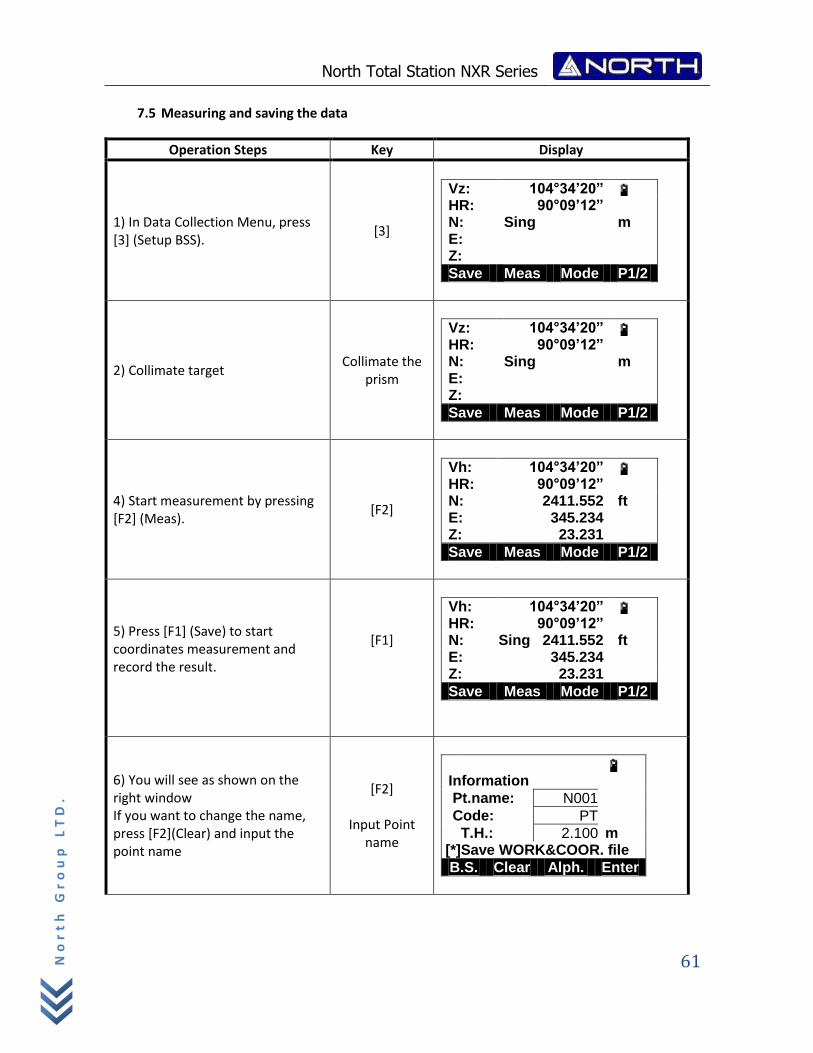
North Total Station NXR Series
61
No
rt
h G
ro
up
LT
D.
7.5 Measuring and saving the data
Operation Steps Key Display
1) In Data Collection Menu, press [3] (Setup BSS).
[3]
Vz: 104°34’20” HR: 90°09’12” N: Sing m E: Z:
Save Meas Mode P1/2
2) Collimate target Collimate the
prism
Vz: 104°34’20” HR: 90°09’12” N: Sing m E: Z:
Save Meas Mode P1/2
4) Start measurement by pressing [F2] (Meas).
[F2]
Vh: 104°34’20” HR: 90°09’12” N: 2411.552 ft E: 345.234 Z: 23.231
Save Meas Mode P1/2
5) Press [F1] (Save) to start coordinates measurement and record the result.
[F1]
Vh: 104°34’20” HR: 90°09’12” N: Sing 2411.552 ft E: 345.234 Z: 23.231
Save Meas Mode P1/2
6) You will see as shown on the right window If you want to change the name, press [F2](Clear) and input the point name
[F2]
Input Point name
Information
Pt.name: N001
Code: PT
T.H.: 2.100 m [*]Save WORK&COOR. file
B.S. Clear Alph. Enter
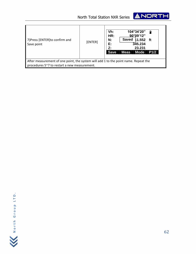
North Total Station NXR Series
62
No
rt
h G
ro
up
LT
D.
7)Press [ENTER]to confirm and Save point
[ENTER]
Vh: 104°34’20” HR: 90°09’12” N: Sing 2411.552 ft E: 345.234 Z: 23.231
Save Meas Mode P1/2
After measurement of one point, the system will add 1 to the point name. Repeat the procedures 5~7 to restart a new measurement.
Saved
North Total Station NXR Series
63
No
rt
h G
ro
up
LT
D.
8. Setout measurement
Setout measurement is used to Setout the required point. The difference between the previously
inputted data to the instrument(the Setout data)and the measured value can be displayed by
measuring the horizontal angle, distance or coordinates of the sighted point.
The horizontal angle difference and distance difference are calculated and displayed using the
following formulas:
Horizontal angle difference
dHA =Horizontal angle of Setout data – measured horizontal angle
Distance difference
Distance Displayed item
SD: S-O SD=measured slope distance – slope distance of Setout data
HD: S-O HD=measured horizontal distance – horizontal distance of Setout data
VD: S-O VD=measured height difference – height difference of Setout data
There are the following steps:
1. Setting occupied point.
2. Setting backsight point and azimuth angle.
3. Input layout point coordinates, and then starts.
NOTE:
Setout data can be input in various modes: SD, HD, VD, coordinates and REM
measurement.
EDM settings could be set in this mode.
8.1 Preparation
Setting the Grid Scale
Calculation Formula
1)Elevation factor Elevation factor=R/(R+ELEV)
R:The average radius of the earth
ELEV:The elevation above the mean sea level
2)Scale factor:
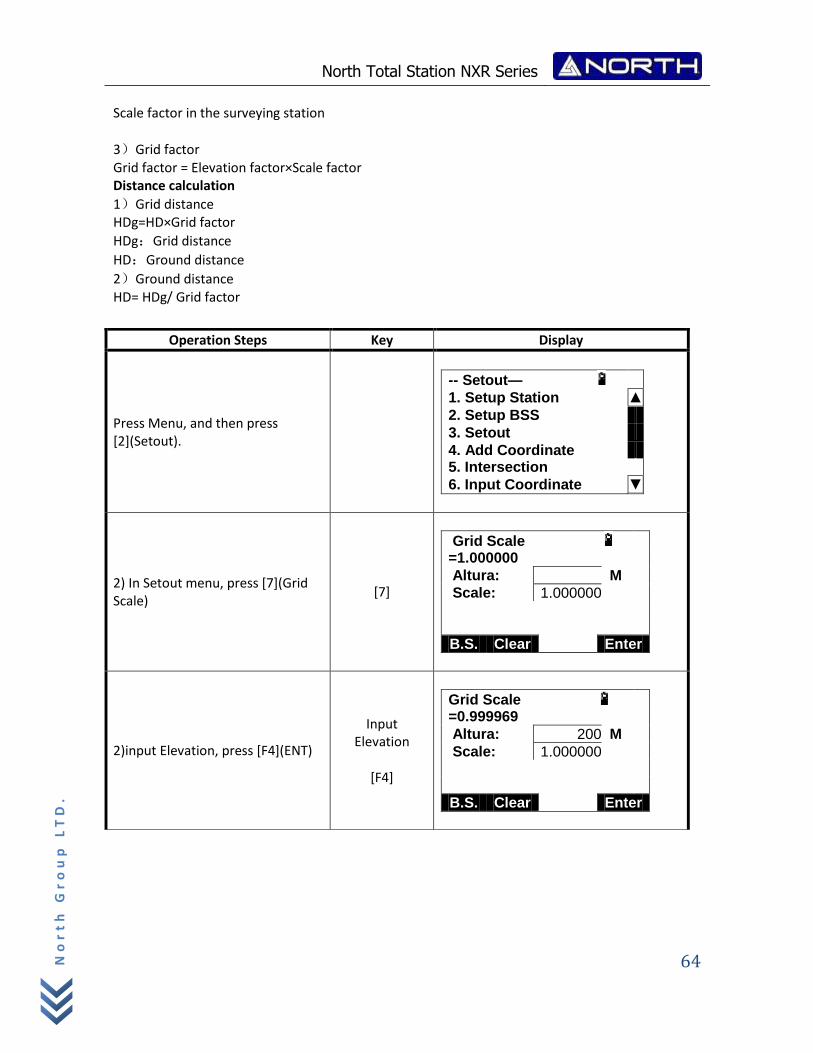
North Total Station NXR Series
64
No
rt
h G
ro
up
LT
D.
Scale factor in the surveying station
3)Grid factor Grid factor = Elevation factor×Scale factor Distance calculation
1)Grid distance HDg=HD×Grid factor
HDg:Grid distance
HD:Ground distance
2)Ground distance HD= HDg/ Grid factor
Operation Steps Key Display
Press Menu, and then press [2](Setout).
-- Setout—
1. Setup Station ▲
2. Setup BSS
3. Setout
4. Add Coordinate 5. Intersection
6. Input Coordinate ▼
2) In Setout menu, press [7](Grid Scale)
[7]
Grid Scale
=1.000000
Altura: M
Scale: 1.000000
B.S. Clear Enter
2)input Elevation, press [F4](ENT)
Input Elevation
[F4]
Grid Scale
=0.999969
Altura: 200 M
Scale: 1.000000
B.S. Clear Enter
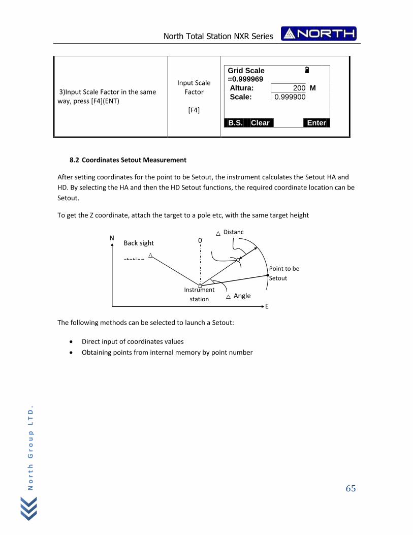
North Total Station NXR Series
65
No
rt
h G
ro
up
LT
D.
8.2 Coordinates Setout Measurement
After setting coordinates for the point to be Setout, the instrument calculates the Setout HA and
HD. By selecting the HA and then the HD Setout functions, the required coordinate location can be
Setout.
To get the Z coordinate, attach the target to a pole etc, with the same target height
The following methods can be selected to launch a Setout:
Direct input of coordinates values
Obtaining points from internal memory by point number
3)Input Scale Factor in the same way, press [F4](ENT)
Input Scale Factor
[F4]
Grid Scale
=0.999969
Altura: 200 M
Scale: 0.999900
B.S. Clear Enter
Point to be
Setout
Back sight
station
Instrument
station
Distanc
ee
Angle
0
E
N
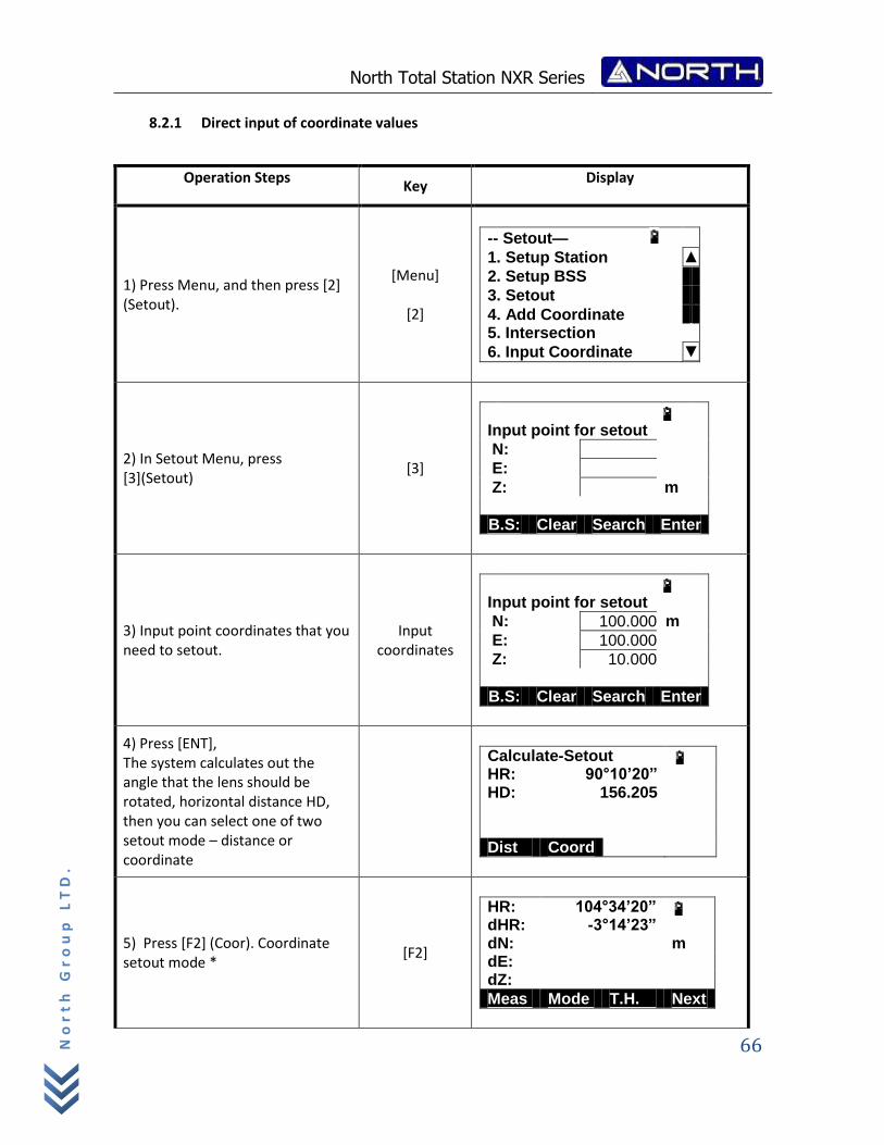
North Total Station NXR Series
66
No
rt
h G
ro
up
LT
D.
8.2.1 Direct input of coordinate values
Operation Steps Key
Display
1) Press Menu, and then press [2] (Setout).
[Menu]
[2]
-- Setout—
1. Setup Station ▲
2. Setup BSS
3. Setout
4. Add Coordinate 5. Intersection
6. Input Coordinate ▼
2) In Setout Menu, press [3](Setout)
[3]
Input point for setout
N:
E:
Z: m
B.S: Clear Search Enter
3) Input point coordinates that you need to setout.
Input coordinates
Input point for setout
N: 100.000 m
E: 100.000
Z: 10.000
B.S: Clear Search Enter
4) Press [ENT], The system calculates out the angle that the lens should be rotated, horizontal distance HD, then you can select one of two setout mode – distance or coordinate
Calculate-Setout HR: 90°10’20” HD: 156.205 Dist Coord
5) Press [F2] (Coor). Coordinate setout mode *
[F2]
HR: 104°34’20” dHR: -3°14’23” dN: m dE: dZ:
Meas Mode T.H. Next
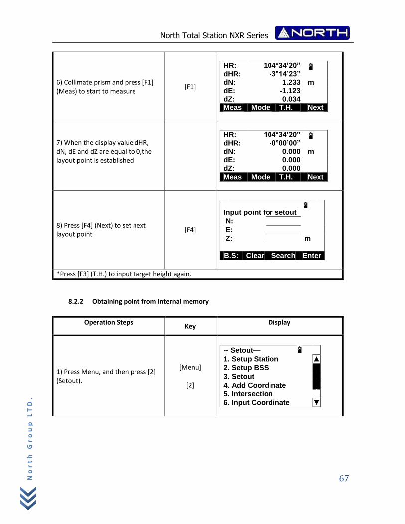
North Total Station NXR Series
67
No
rt
h G
ro
up
LT
D.
8.2.2 Obtaining point from internal memory
6) Collimate prism and press [F1] (Meas) to start to measure
[F1]
HR: 104°34’20” dHR: -3°14’23” dN: 1.233 m dE: -1.123 dZ: 0.034
Meas Mode T.H. Next
7) When the display value dHR, dN, dE and dZ are equal to 0,the layout point is established
HR: 104°34’20” dHR: -0°00’00” dN: 0.000 m dE: 0.000 dZ: 0.000
Meas Mode T.H. Next
8) Press [F4] (Next) to set next layout point
[F4]
Input point for setout
N:
E:
Z: m
B.S: Clear Search Enter
*Press [F3] (T.H.) to input target height again.
Operation Steps Key
Display
1) Press Menu, and then press [2] (Setout).
[Menu]
[2]
-- Setout—
1. Setup Station ▲
2. Setup BSS
3. Setout
4. Add Coordinate 5. Intersection
6. Input Coordinate ▼
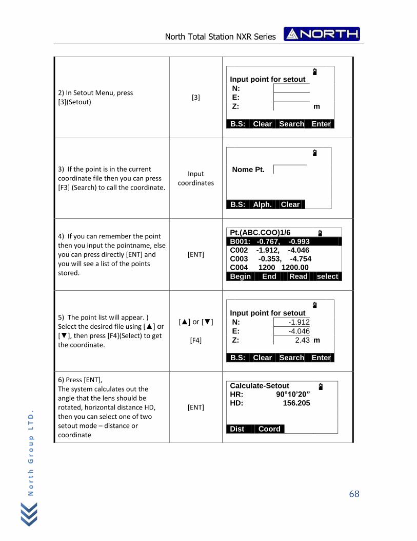
North Total Station NXR Series
68
No
rt
h G
ro
up
LT
D.
2) In Setout Menu, press [3](Setout)
[3]
Input point for setout
N:
E:
Z: m
B.S: Clear Search Enter
3) If the point is in the current coordinate file then you can press [F3] (Search) to call the coordinate.
Input coordinates
Nome Pt.
B.S: Alph. Clear
4) If you can remember the point then you input the pointname, else you can press directly [ENT] and you will see a list of the points stored.
[ENT]
Pt.(ABC.COO)1/6 B001: -0.767, -0.993 C002 -1.912, -4.046 C003 -0.353, -4.754 C004 1200 1200.00
Begin End Read select
5) The point list will appear. ) Select the desired file using [▲] or
[▼], then press [F4](Select) to get the coordinate.
[▲] or [▼]
[F4]
Input point for setout
N: -1.912
E: -4.046
Z: 2.43 m
B.S: Clear Search Enter
6) Press [ENT], The system calculates out the angle that the lens should be rotated, horizontal distance HD, then you can select one of two setout mode – distance or coordinate
[ENT]
Calculate-Setout HR: 90°10’20” HD: 156.205 Dist Coord
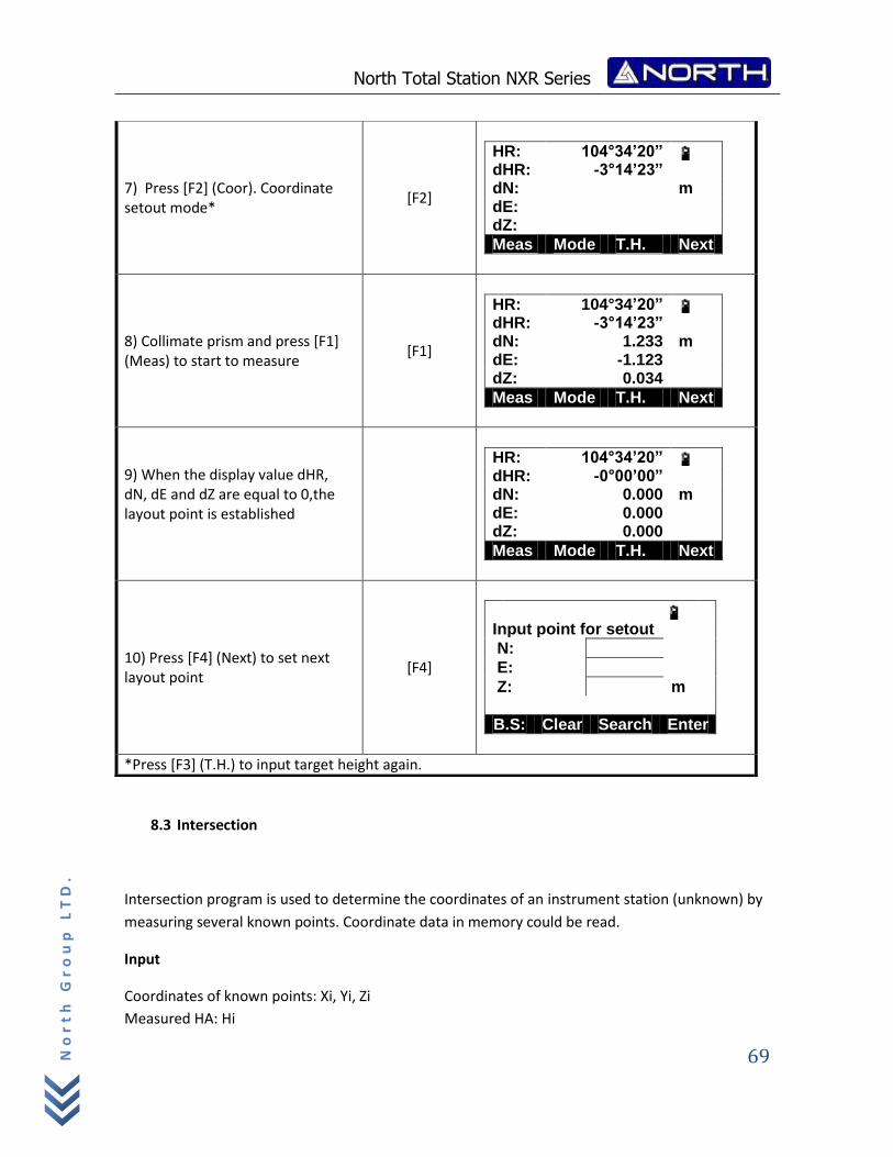
North Total Station NXR Series
69
No
rt
h G
ro
up
LT
D.
8.3 Intersection
Intersection program is used to determine the coordinates of an instrument station (unknown) by
measuring several known points. Coordinate data in memory could be read.
Input
Coordinates of known points: Xi, Yi, Zi
Measured HA: Hi
7) Press [F2] (Coor). Coordinate setout mode*
[F2]
HR: 104°34’20” dHR: -3°14’23” dN: m dE: dZ:
Meas Mode T.H. Next
8) Collimate prism and press [F1] (Meas) to start to measure
[F1]
HR: 104°34’20” dHR: -3°14’23” dN: 1.233 m dE: -1.123 dZ: 0.034
Meas Mode T.H. Next
9) When the display value dHR, dN, dE and dZ are equal to 0,the layout point is established
HR: 104°34’20” dHR: -0°00’00” dN: 0.000 m dE: 0.000 dZ: 0.000
Meas Mode T.H. Next
10) Press [F4] (Next) to set next layout point
[F4]
Input point for setout
N:
E:
Z: m
B.S: Clear Search Enter
*Press [F3] (T.H.) to input target height again.
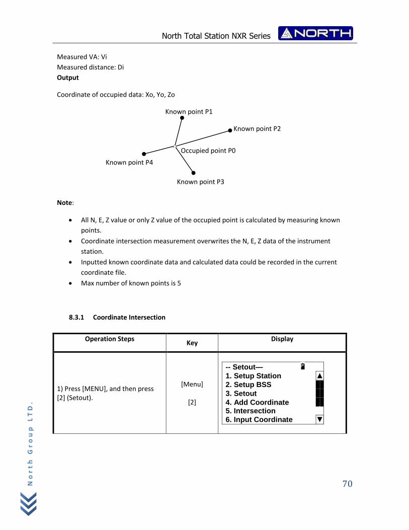
North Total Station NXR Series
70
No
rt
h G
ro
up
LT
D.
Measured VA: Vi
Measured distance: Di
Output
Coordinate of occupied data: Xo, Yo, Zo
Note:
All N, E, Z value or only Z value of the occupied point is calculated by measuring known
points.
Coordinate intersection measurement overwrites the N, E, Z data of the instrument
station.
Inputted known coordinate data and calculated data could be recorded in the current
coordinate file.
Max number of known points is 5
8.3.1 Coordinate Intersection
Operation Steps Key
Display
1) Press [MENU], and then press [2] (Setout).
[Menu]
[2]
-- Setout—
1. Setup Station ▲
2. Setup BSS
3. Setout
4. Add Coordinate 5. Intersection
6. Input Coordinate ▼
Known point P4
Known point P1
Known point P2
Known point P3
Occupied point P0
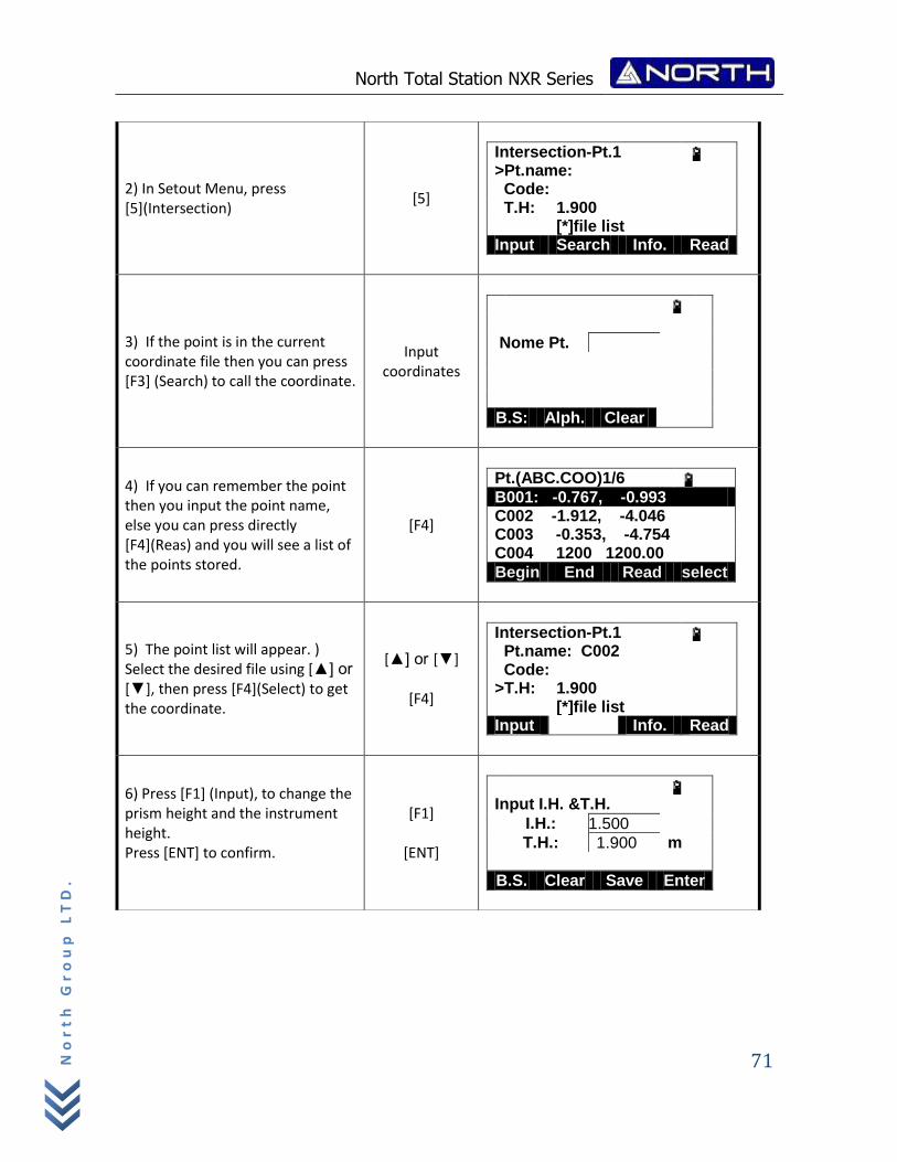
North Total Station NXR Series
71
No
rt
h G
ro
up
LT
D.
2) In Setout Menu, press [5](Intersection)
[5]
Intersection-Pt.1 >Pt.name: Code: T.H: 1.900 [*]file list Input Search Info. Read
3) If the point is in the current coordinate file then you can press [F3] (Search) to call the coordinate.
Input coordinates
Nome Pt.
B.S: Alph. Clear
4) If you can remember the point then you input the point name, else you can press directly [F4](Reas) and you will see a list of the points stored.
[F4]
Pt.(ABC.COO)1/6 B001: -0.767, -0.993 C002 -1.912, -4.046 C003 -0.353, -4.754 C004 1200 1200.00
Begin End Read select
5) The point list will appear. ) Select the desired file using [▲] or
[▼], then press [F4](Select) to get the coordinate.
[▲] or [▼]
[F4]
Intersection-Pt.1 Pt.name: C002 Code: >T.H: 1.900 [*]file list Input Info. Read
6) Press [F1] (Input), to change the prism height and the instrument height. Press [ENT] to confirm.
[F1]
[ENT]
Input I.H. &T.H.
I.H.: 1.500
T.H.: 1.900 m
B.S. Clear Save Enter
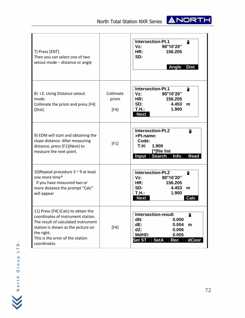
North Total Station NXR Series
72
No
rt
h G
ro
up
LT
D.
7) Press [ENT]. Then you can select one of two setout mode – distance or angle
Intersection-Pt.1 Vz: 90°10’20” HR: 156.205 SD: Angle Dist
8) I.E. Using Distance setout mode. Collimate the prism and press [F4] (Dist).
Collimate prism
[F4]
Intersection-Pt.1 Vz: 90°10’20” HR: 156.205 SD: 4.453 m T.H.: 1.900 Next
9) EDM will start and obtaining the slope distance. After measuring distance, press [F1](Next) to measure the next point.
[F1]
Intersection-Pt.2 >Pt.name: Code: T.H: 1.900 [*]file list Input Search Info. Read
10)Repeat procedure 3 ~ 9 at least one more time* if you have measured two or more distance the prompt “Calc” will appear
Intersection-Pt.2 Vz: 90°10’20” HR: 156.205 SD: 4.453 m T.H.: 1.900 Next Calc
11) Press [F4] (Calc) to obtain the coordinates of instrument station. The result of calculated instrument station is shown as the picture on the right. This is the error of the station coordinates
[F4]
Intersection-result dN: 0.000 dE: 0.004 m dZ: 0.006 MdHD: 0.005
Set ST SetA Rec dCoor
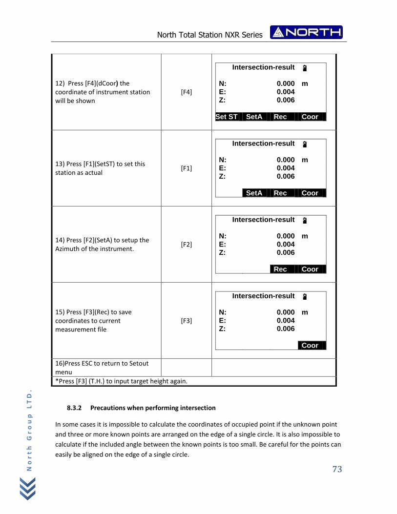
North Total Station NXR Series
73
No
rt
h G
ro
up
LT
D.
8.3.2 Precautions when performing intersection
In some cases it is impossible to calculate the coordinates of occupied point if the unknown point
and three or more known points are arranged on the edge of a single circle. It is also impossible to
calculate if the included angle between the known points is too small. Be careful for the points can
easily be aligned on the edge of a single circle.
12) Press [F4](dCoor) the coordinate of instrument station will be shown
[F4]
Intersection-result
N: 0.000 m E: 0.004 Z: 0.006
Set ST SetA Rec Coor
13) Press [F1](SetST) to set this station as actual
[F1]
Intersection-result
N: 0.000 m E: 0.004 Z: 0.006
SetA Rec Coor
14) Press [F2](SetA) to setup the Azimuth of the instrument.
[F2]
Intersection-result
N: 0.000 m E: 0.004 Z: 0.006
Rec Coor
15) Press [F3](Rec) to save coordinates to current measurement file
[F3]
Intersection-result
N: 0.000 m E: 0.004 Z: 0.006
Coor
16)Press ESC to return to Setout menu
*Press [F3] (T.H.) to input target height again.
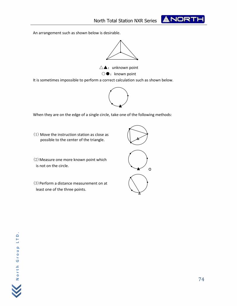
North Total Station NXR Series
74
No
rt
h G
ro
up
LT
D.
An arrangement such as shown below is desirable.
△▲:unknown point
○●:known point
It is sometimes impossible to perform a correct calculation such as shown below.
When they are on the edge of a single circle, take one of the following methods:
(1) Move the instruction station as close as possible to the center of the triangle.
(2)Measure one more known point which
is not on the circle.
(3)Perform a distance measurement on at
least one of the three points.
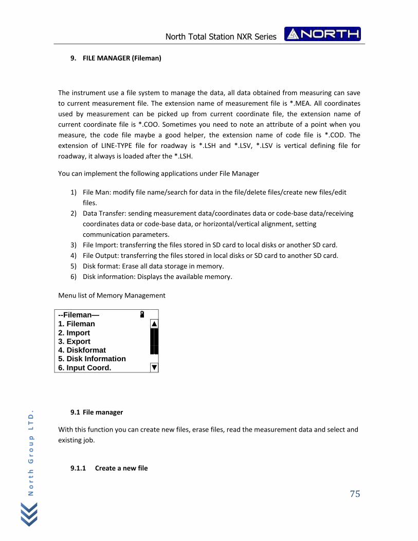
North Total Station NXR Series
75
No
rt
h G
ro
up
LT
D.
9. FILE MANAGER (Fileman)
The instrument use a file system to manage the data, all data obtained from measuring can save
to current measurement file. The extension name of measurement file is *.MEA. All coordinates
used by measurement can be picked up from current coordinate file, the extension name of
current coordinate file is *.COO. Sometimes you need to note an attribute of a point when you
measure, the code file maybe a good helper, the extension name of code file is *.COD. The
extension of LINE-TYPE file for roadway is *.LSH and *.LSV, *.LSV is vertical defining file for
roadway, it always is loaded after the *.LSH.
You can implement the following applications under File Manager
1) File Man: modify file name/search for data in the file/delete files/create new files/edit
files.
2) Data Transfer: sending measurement data/coordinates data or code‐base data/receiving
coordinates data or code‐base data, or horizontal/vertical alignment, setting
communication parameters.
3) File Import: transferring the files stored in SD card to local disks or another SD card.
4) File Output: transferring the files stored in local disks or SD card to another SD card.
5) Disk format: Erase all data storage in memory.
6) Disk information: Displays the available memory.
Menu list of Memory Management
--Fileman—
1. Fileman ▲
2. Import 3. Export 4. Diskformat 5. Disk Information
6. Input Coord. ▼
9.1 File manager
With this function you can create new files, erase files, read the measurement data and select and
existing job.
9.1.1 Create a new file
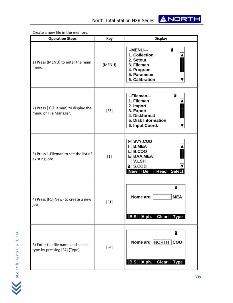
North Total Station NXR Series
76
No
rt
h G
ro
up
LT
D.
Create a new file in the memory.
Operation Steps Key Display
1) Press (MENU) to enter the main menu.
(MENU)
--MENU—
1. Collection ▲
2. Setout 3. Fileman 4. Program 5. Parameter
6. Calibration ▼
2) Press [3](Fileman) to display the menu of File Manager.
[F3]
--Fileman—
1. Fileman ▲
2. Import 3. Export 4. Diskformat 5. Disk Information
6. Input Coord. ▼
3) Press 1.Fileman to see the list of existing jobs.
[1]
F SVY.COD I B.MEA ▲
L B.COO E BAA.MEA V.LSH
S.COD ▼
New Del Read Select
4) Press [F1](New) to create a new job
[F1]
Nome arq. .MEA
B.S Alph. Clear Type
5) Enter the file name and select type by pressing [F4] (Type).
[F4]
Nome arq. NORTH .COO
B.S Alph. Clear Type
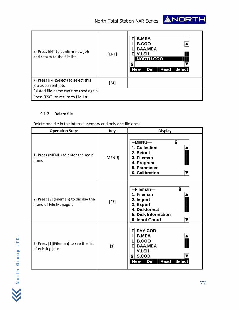
North Total Station NXR Series
77
No
rt
h G
ro
up
LT
D.
6) Press ENT to confirm new job and return to the file list
[ENT]
F B.MEA I B.COO ▲
L BAA.MEA E V.LSH NORTH.COO
▼
New Del Read Select
7) Press [F4](Select) to select this job as current job.
[F4]
Existed file name can’t be used again.
Press [ESC], to return to file list.
9.1.2 Delete file
Delete one file in the internal memory and only one file once.
Operation Steps Key Display
1) Press (MENU) to enter the main menu.
(MENU)
--MENU—
1. Collection ▲
2. Setout 3. Fileman 4. Program 5. Parameter
6. Calibration ▼
2) Press [3] (Fileman) to display the menu of File Manager.
[F3]
--Fileman—
1. Fileman ▲
2. Import 3. Export 4. Diskformat 5. Disk Information
6. Input Coord. ▼
3) Press [1](Fileman) to see the list of existing jobs.
[1]
F SVY.COD I B.MEA ▲
L B.COO E BAA.MEA V.LSH
S.COD ▼
New Del Read Select
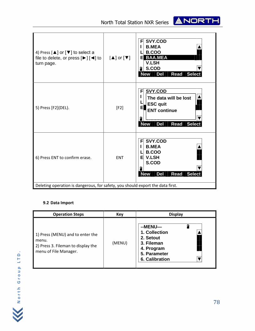
North Total Station NXR Series
78
No
rt
h G
ro
up
LT
D.
4) Press [▲] or [▼] to select a
file to delete, or press [►] [◄] to turn page.
[▲] or [▼]
F SVY.COD I B.MEA ▲
L B.COO E BAA.MEA V.LSH
S.COD ▼
New Del Read Select
5) Press [F2](DEL). [F2]
F SVY.COD I B.MEA ▲
L B.COO E BAA.MEA V.LSH
S.COD ▼
New Del Read Select
6) Press ENT to confirm erase. ENT
F SVY.COD I B.MEA ▲
L B.COO E V.LSH S.COD
▼
New Del Read Select
Deleting operation is dangerous, for safety, you should export the data first.
9.2 Data Import
Operation Steps Key Display
1) Press (MENU) and to enter the menu. 2) Press 3. Fileman to display the menu of File Manager.
(MENU)
--MENU—
1. Collection ▲
2. Setout 3. Fileman 4. Program 5. Parameter
6. Calibration ▼
The data will be lost
ESC quit
ENT continue
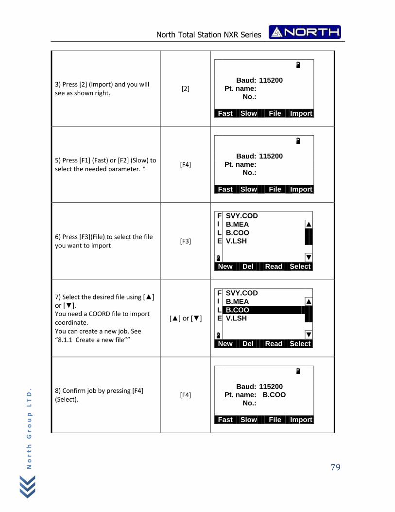
North Total Station NXR Series
79
No
rt
h G
ro
up
LT
D.
3) Press [2] (Import) and you will see as shown right.
[2]
Baud: 115200 Pt. name:
No.:
Fast Slow File Import
5) Press [F1] (Fast) or [F2] (Slow) to select the needed parameter. *
[F4]
Baud: 115200 Pt. name:
No.:
Fast Slow File Import
6) Press [F3](File) to select the file you want to import
[F3]
F SVY.COD I B.MEA ▲
L B.COO E V.LSH
▼
New Del Read Select
7) Select the desired file using [▲]
or [▼]. You need a COORD file to import coordinate. You can create a new job. See “8.1.1 Create a new file””
[▲] or [▼]
F SVY.COD I B.MEA ▲
L B.COO E V.LSH
▼
New Del Read Select
8) Confirm job by pressing [F4] (Select).
[F4]
Baud: 115200 Pt. name: B.COO
No.:
Fast Slow File Import
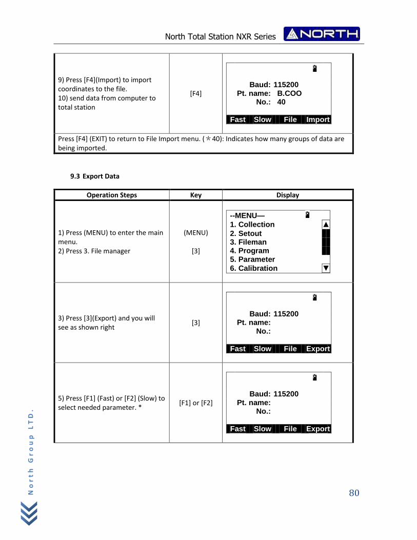
North Total Station NXR Series
80
No
rt
h G
ro
up
LT
D.
9) Press [F4](Import) to import coordinates to the file. 10) send data from computer to total station
[F4]
Baud: 115200 Pt. name: B.COO
No.: 40
Fast Slow File Import
Press [F4] (EXIT) to return to File Import menu. (*40): Indicates how many groups of data are being imported.
9.3 Export Data
Operation Steps Key Display
1) Press (MENU) to enter the main menu. 2) Press 3. File manager
(MENU)
[3]
--MENU—
1. Collection ▲
2. Setout 3. Fileman 4. Program 5. Parameter
6. Calibration ▼
3) Press [3](Export) and you will see as shown right
[3]
Baud: 115200 Pt. name:
No.:
Fast Slow File Export
5) Press [F1] (Fast) or [F2] (Slow) to select needed parameter. *
[F1] or [F2]
Baud: 115200 Pt. name:
No.:
Fast Slow File Export
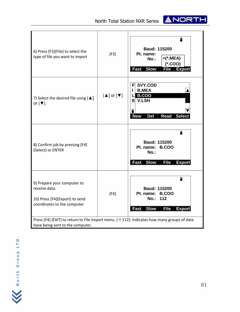
North Total Station NXR Series
81
No
rt
h G
ro
up
LT
D.
6) Press [F3](File) to select the type of file you want to import
[F3]
Baud: 115200 Pt. name:
No.:
Fast Slow File Export
7) Select the desired file using [▲]
or [▼].
[▲] or [▼]
F SVY.COD I B.MEA ▲
L B.COO E V.LSH
▼
New Del Read Select
8) Confirm job by pressing [F4] (Select) or ENTER
Baud: 115200 Pt. name: B.COO
No.:
Fast Slow File Export
9) Prepare your computer to receive data. 10) Press [F4](Export) to send coordinates to the computer
[F4]
Baud: 115200 Pt. name: B.COO
No.: 112
Fast Slow File Export
Press [F4] (EXIT) to return to File Import menu. (*112): Indicates how many groups of data have being sent to the computer.
>(*.MEA)
(*.COO)
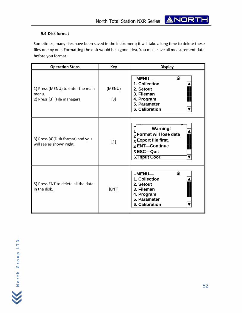
North Total Station NXR Series
82
No
rt
h G
ro
up
LT
D.
9.4 Disk format
Sometimes, many files have been saved in the instrument; it will take a long time to delete these
files one by one. Formatting the disk would be a good idea. You must save all measurement data
before you format.
Operation Steps Key Display
1) Press (MENU) to enter the main menu. 2) Press [3] (File manager)
(MENU)
[3]
--MENU—
1. Collection ▲
2. Setout 3. Fileman 4. Program 5. Parameter
6. Calibration ▼
3) Press [4](Disk format) and you will see as shown right.
[4]
-- Fileman—
1. Fileman ▲
2. Import
3. Export
4. Disk format 5. Disk information
6. Input Coor. ▼
5) Press ENT to delete all the data in the disk.
[ENT]
--MENU—
1. Collection ▲
2. Setout 3. Fileman 4. Program 5. Parameter
6. Calibration ▼
Warning!
Format will lose data
Export file first.
ENT—Continue
ESC—Quit
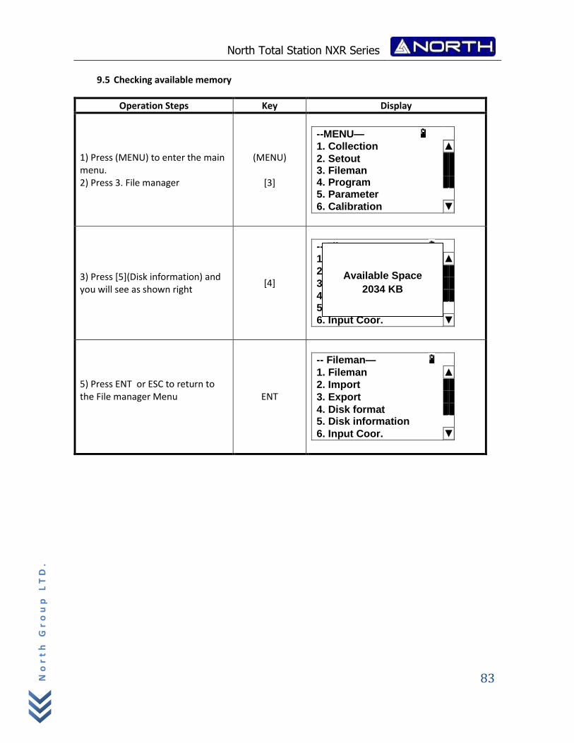
North Total Station NXR Series
83
No
rt
h G
ro
up
LT
D.
9.5 Checking available memory
Operation Steps Key Display
1) Press (MENU) to enter the main menu. 2) Press 3. File manager
(MENU)
[3]
--MENU—
1. Collection ▲
2. Setout 3. Fileman 4. Program 5. Parameter
6. Calibration ▼
3) Press [5](Disk information) and you will see as shown right
[4]
-- Fileman—
1. Fileman ▲
2. Import
3. Export
4. Disk format 5. Disk information
6. Input Coor. ▼
5) Press ENT or ESC to return to the File manager Menu
ENT
-- Fileman—
1. Fileman ▲
2. Import
3. Export
4. Disk format 5. Disk information
6. Input Coor. ▼
Available Space
2034 KB
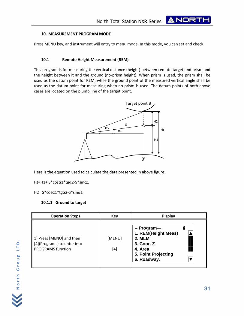
North Total Station NXR Series
84
No
rt
h G
ro
up
LT
D.
10. MEASUREMENT PROGRAM MODE
Press MENU key, and instrument will entry to menu mode. In this mode, you can set and check.
10.1 Remote Height Measurement (REM)
This program is for measuring the vertical distance (height) between remote target and prism and the height between it and the ground (no-prism height). When prism is used, the prism shall be used as the datum point for REM; while the ground point of the measured vertical angle shall be used as the datum point for measuring when no prism is used. The datum points of both above cases are located on the plumb line of the target point.
Here is the equation used to calculate the data presented in above figure:
Ht=H1+ S*cosα1*tgα2-S*sinα1
H2= S*cosα1*tgα2-S*sinα1
10.1.1 Ground to target
Operation Steps Key Display
1) Press [MENU] and then [4](Programs) to enter into PROGRAMS function
[MENU]
[4]
-- Program—
1. REM(Height Meas) ▲
2. MLM
3. Coor. Z
4. Area 5. Point Projecting
6. Roadway. ▼
α1 Ht
H2
H1
B’
S
Target point B
α2
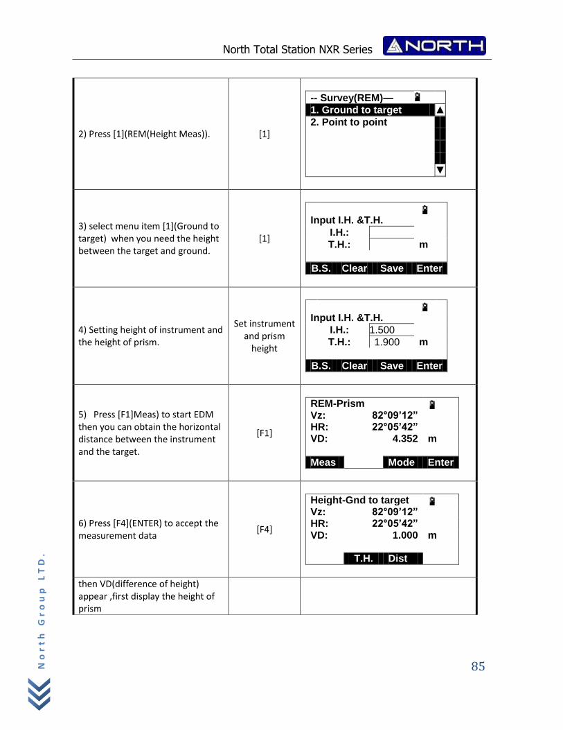
North Total Station NXR Series
85
No
rt
h G
ro
up
LT
D.
2) Press [1](REM(Height Meas)). [1]
-- Survey(REM)—
1. Ground to target ▲
2. Point to point
▼
3) select menu item [1](Ground to target) when you need the height between the target and ground.
[1]
Input I.H. &T.H.
I.H.:
T.H.: m
B.S. Clear Save Enter
4) Setting height of instrument and the height of prism.
Set instrument and prism
height
Input I.H. &T.H.
I.H.: 1.500
T.H.: 1.900 m
B.S. Clear Save Enter
5) Press [F1]Meas) to start EDM then you can obtain the horizontal distance between the instrument and the target.
[F1]
REM-Prism Vz: 82°09’12” HR: 22°05’42” VD: 4.352 m
Meas Mode Enter
6) Press [F4](ENTER) to accept the measurement data
[F4]
Height-Gnd to target Vz: 82°09’12” HR: 22°05’42” VD: 1.000 m T.H. Dist Enter
then VD(difference of height) appear ,first display the height of prism
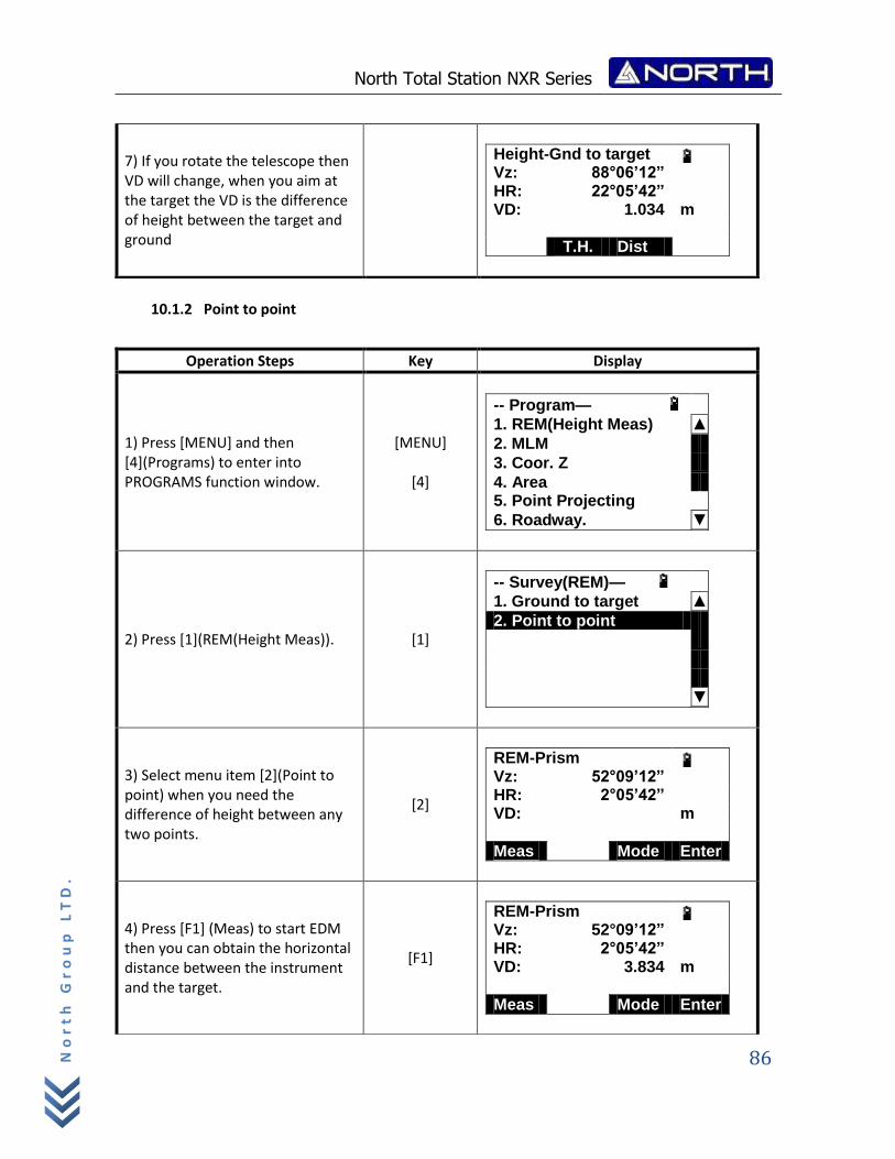
North Total Station NXR Series
86
No
rt
h G
ro
up
LT
D.
10.1.2 Point to point
7) If you rotate the telescope then VD will change, when you aim at the target the VD is the difference of height between the target and ground
Height-Gnd to target Vz: 88°06’12” HR: 22°05’42” VD: 1.034 m T.H. Dist Enter
Operation Steps Key Display
1) Press [MENU] and then [4](Programs) to enter into PROGRAMS function window.
[MENU]
[4]
-- Program—
1. REM(Height Meas) ▲
2. MLM
3. Coor. Z
4. Area 5. Point Projecting
6. Roadway. ▼
2) Press [1](REM(Height Meas)). [1]
-- Survey(REM)—
1. Ground to target ▲
2. Point to point
▼
3) Select menu item [2](Point to point) when you need the difference of height between any two points.
[2]
REM-Prism Vz: 52°09’12” HR: 2°05’42” VD: m
Meas Mode Enter
4) Press [F1] (Meas) to start EDM then you can obtain the horizontal distance between the instrument and the target.
[F1]
REM-Prism Vz: 52°09’12” HR: 2°05’42” VD: 3.834 m
Meas Mode Enter
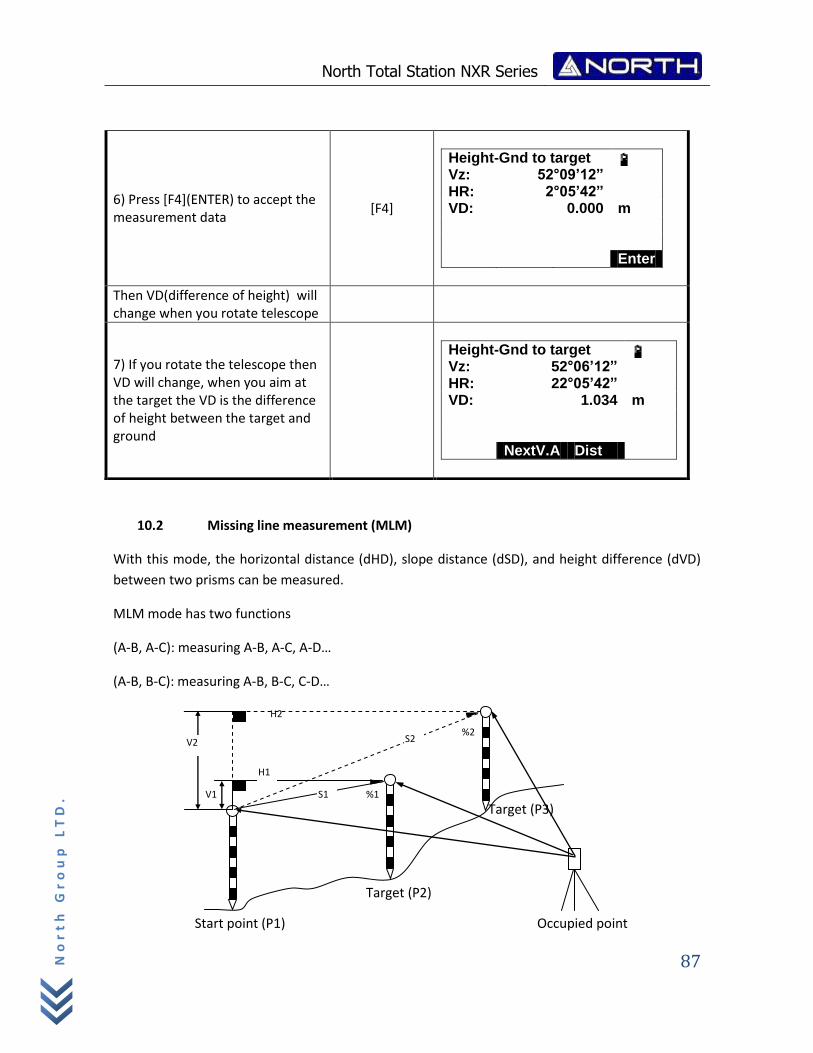
North Total Station NXR Series
87
No
rt
h G
ro
up
LT
D.
10.2 Missing line measurement (MLM)
With this mode, the horizontal distance (dHD), slope distance (dSD), and height difference (dVD)
between two prisms can be measured.
MLM mode has two functions
(A-B, A-C): measuring A-B, A-C, A-D…
(A-B, B-C): measuring A-B, B-C, C-D…
6) Press [F4](ENTER) to accept the measurement data
[F4]
Height-Gnd to target Vz: 52°09’12” HR: 2°05’42” VD: 0.000 m Enter
Then VD(difference of height) will change when you rotate telescope
7) If you rotate the telescope then VD will change, when you aim at the target the VD is the difference of height between the target and ground
Height-Gnd to target Vz: 52°06’12” HR: 22°05’42” VD: 1.034 m NextV.A Dist Enter
H2
H1
S2
S1 %1
%2 V2
V1
Target (P2)
Start point (P1)
Target (P3)
Occupied point
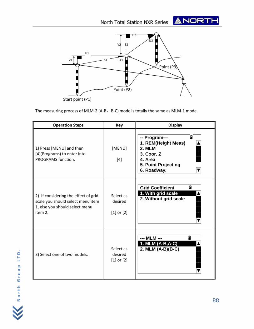
North Total Station NXR Series
88
No
rt
h G
ro
up
LT
D.
The measuring process of MLM-2 (A-B,B-C) mode is totally the same as MLM-1 mode.
Operation Steps Key Display
1) Press [MENU] and then [4](Programs) to enter into PROGRAMS function.
[MENU]
[4]
-- Program—
1. REM(Height Meas) ▲
2. MLM
3. Coor. Z
4. Area 5. Point Projecting
6. Roadway. ▼
2) If considering the effect of grid scale you should select menu item 1, else you should select menu item 2.
Select as desired
[1] or [2]
Grid Coefficient
1. With grid scale ▲
2. Without grid scale
▼
3) Select one of two models. Select as desired
[1] or [2]
--- MLM ---
1. MLM (A-B,A-C) ▲
2. MLM (A-B)(B-C)
▼
H2
H1
S2
S1 %1
%2 V2
V1
Start point (P1)
Point (P2)
Point (P3)
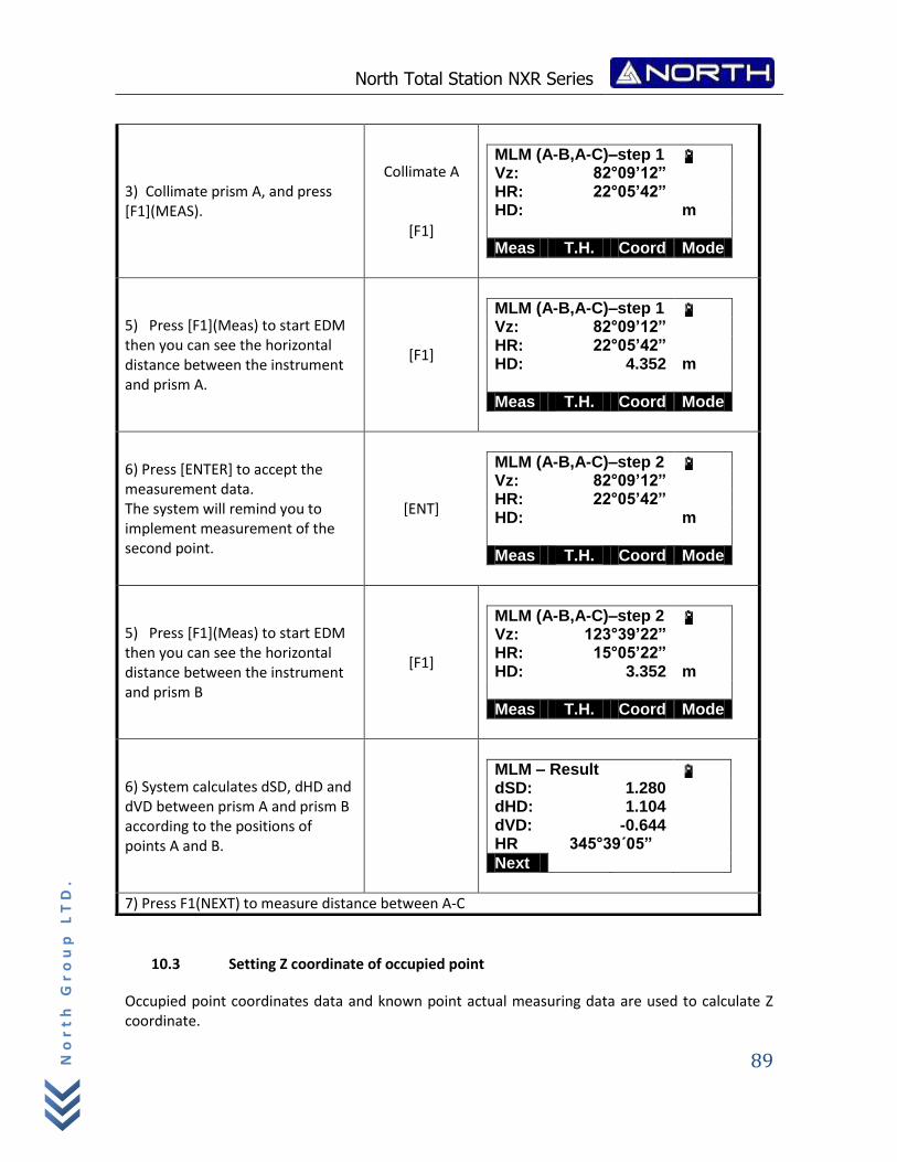
North Total Station NXR Series
89
No
rt
h G
ro
up
LT
D.
10.3 Setting Z coordinate of occupied point
Occupied point coordinates data and known point actual measuring data are used to calculate Z coordinate.
3) Collimate prism A, and press [F1](MEAS).
Collimate A
[F1]
MLM (A-B,A-C)–step 1 Vz: 82°09’12” HR: 22°05’42” HD: m
Meas T.H. Coord Mode
5) Press [F1](Meas) to start EDM then you can see the horizontal distance between the instrument and prism A.
[F1]
MLM (A-B,A-C)–step 1 Vz: 82°09’12” HR: 22°05’42” HD: 4.352 m
Meas T.H. Coord Mode
6) Press [ENTER] to accept the measurement data. The system will remind you to implement measurement of the second point.
[ENT]
MLM (A-B,A-C)–step 2 Vz: 82°09’12” HR: 22°05’42” HD: m
Meas T.H. Coord Mode
5) Press [F1](Meas) to start EDM then you can see the horizontal distance between the instrument and prism B
[F1]
MLM (A-B,A-C)–step 2 Vz: 123°39’22” HR: 15°05’22” HD: 3.352 m
Meas T.H. Coord Mode
6) System calculates dSD, dHD and dVD between prism A and prism B according to the positions of points A and B.
MLM – Result dSD: 1.280 dHD: 1.104 dVD: -0.644 HR 345°39´05”
Next
7) Press F1(NEXT) to measure distance between A‐C
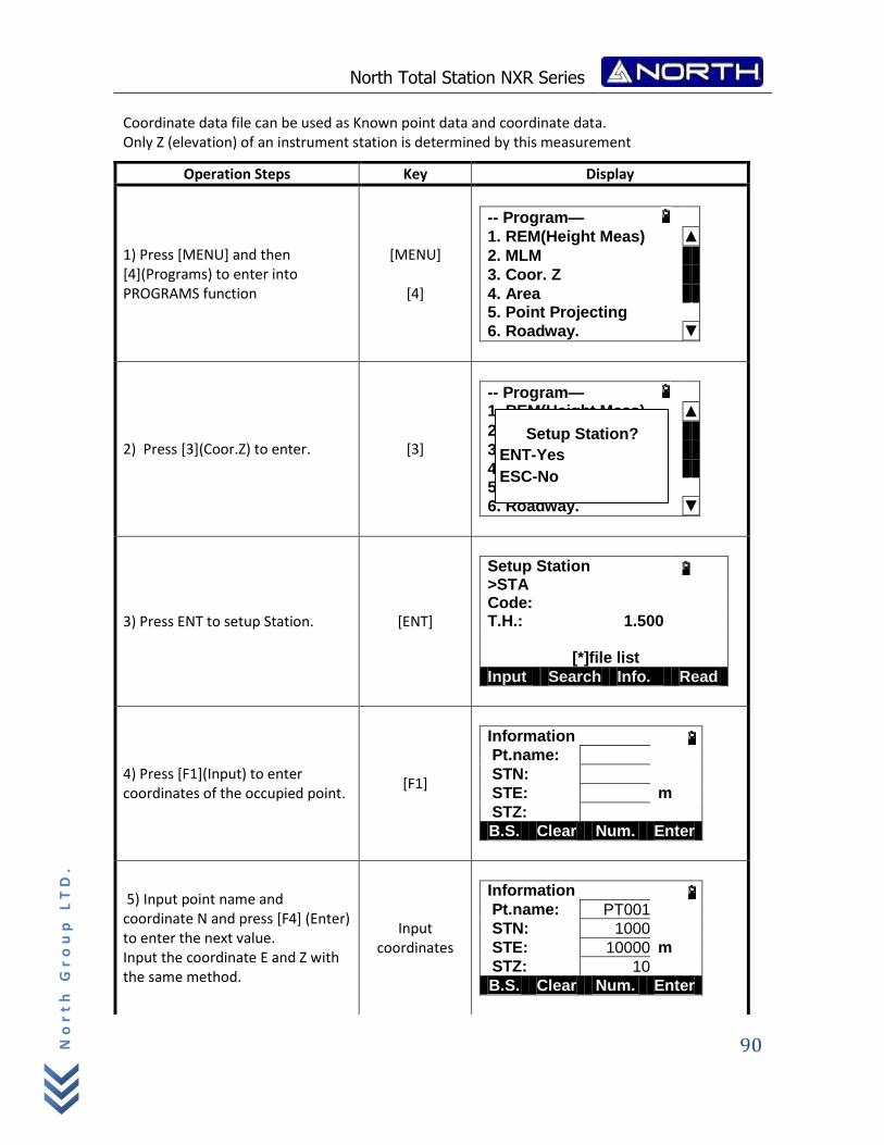
North Total Station NXR Series
90
No
rt
h G
ro
up
LT
D.
Coordinate data file can be used as Known point data and coordinate data. Only Z (elevation) of an instrument station is determined by this measurement
Operation Steps Key Display
1) Press [MENU] and then [4](Programs) to enter into PROGRAMS function
[MENU]
[4]
-- Program—
1. REM(Height Meas) ▲
2. MLM
3. Coor. Z
4. Area 5. Point Projecting
6. Roadway. ▼
2) Press [3](Coor.Z) to enter. [3]
-- Program—
1. REM(Height Meas) ▲
2. MLM
3. Coor. Z
4. Area 5. Point Projecting
6. Roadway. ▼
3) Press ENT to setup Station. [ENT]
Setup Station >STA Code: T.H.: 1.500
[*]file list
Input Search Info. Read
4) Press [F1](Input) to enter coordinates of the occupied point.
[F1]
Information Pt.name:
STN:
STE: m
STZ:
B.S. Clear Num. Enter
5) Input point name and coordinate N and press [F4] (Enter) to enter the next value. Input the coordinate E and Z with the same method.
Input coordinates
Information Pt.name: PT001
STN: 1000
STE: 10000 m
STZ: 10
B.S. Clear Num. Enter
Setup Station?
ENT-Yes
ESC-No
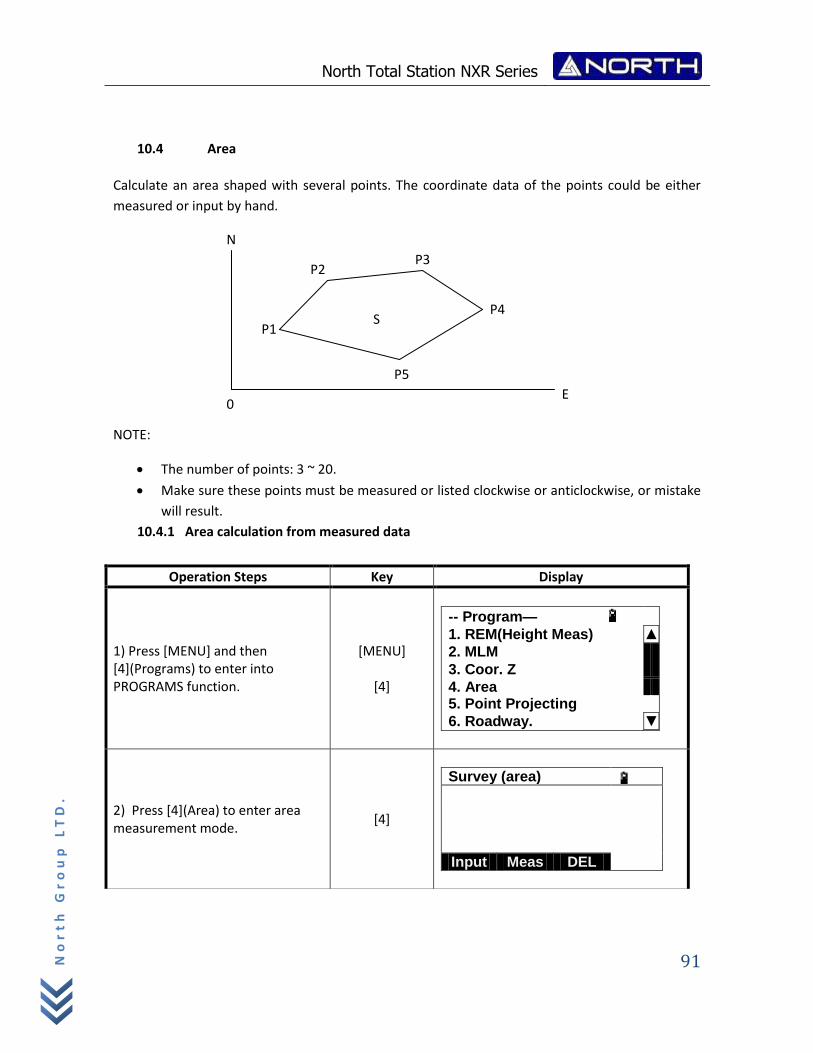
North Total Station NXR Series
91
No
rt
h G
ro
up
LT
D.
10.4 Area
Calculate an area shaped with several points. The coordinate data of the points could be either
measured or input by hand.
NOTE:
The number of points: 3 ~ 20.
Make sure these points must be measured or listed clockwise or anticlockwise, or mistake
will result.
10.4.1 Area calculation from measured data
Operation Steps Key Display
1) Press [MENU] and then [4](Programs) to enter into PROGRAMS function.
[MENU]
[4]
-- Program—
1. REM(Height Meas) ▲
2. MLM
3. Coor. Z
4. Area 5. Point Projecting
6. Roadway. ▼
2) Press [4](Area) to enter area measurement mode.
[4]
Survey (area)
Input Meas DEL
S P1
P2 P3
P4
P5
E 0
N
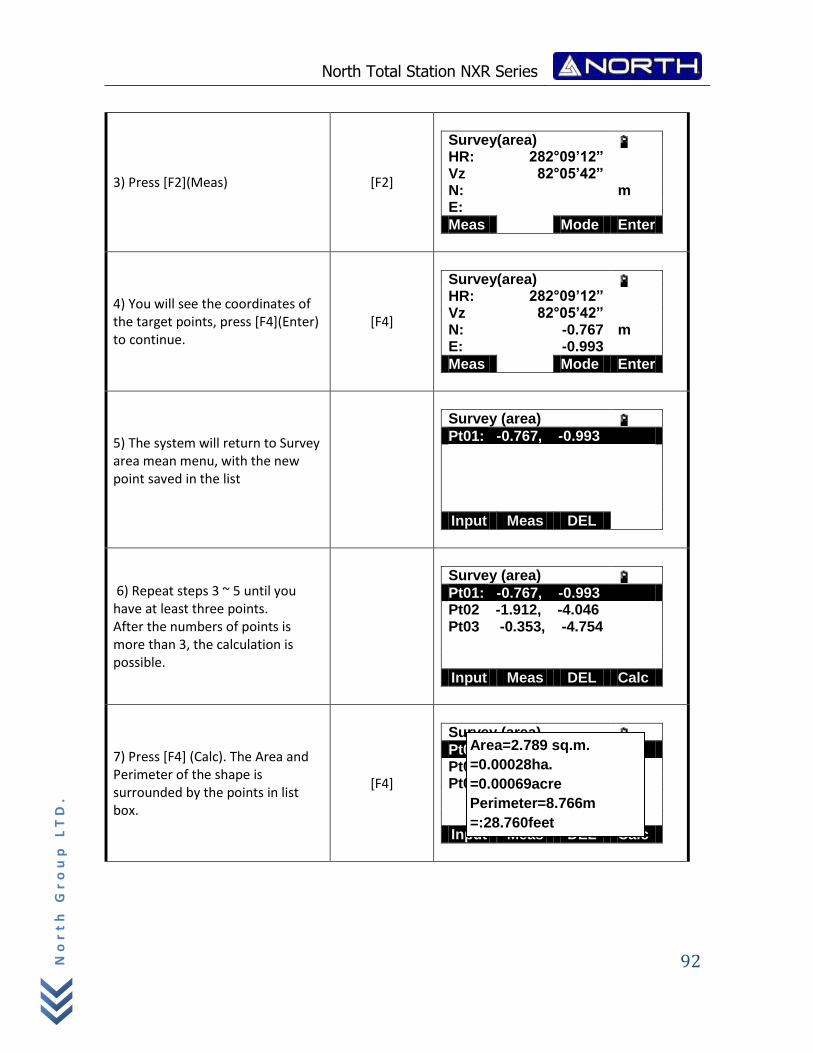
North Total Station NXR Series
92
No
rt
h G
ro
up
LT
D.
3) Press [F2](Meas) [F2]
Survey(area) HR: 282°09’12” Vz 82°05’42” N: m E:
Meas Mode Enter
4) You will see the coordinates of the target points, press [F4](Enter) to continue.
[F4]
Survey(area) HR: 282°09’12” Vz 82°05’42” N: -0.767 m E: -0.993
Meas Mode Enter
5) The system will return to Survey area mean menu, with the new point saved in the list
Survey (area) Pt01: -0.767, -0.993
Input Meas DEL
6) Repeat steps 3 ~ 5 until you have at least three points. After the numbers of points is more than 3, the calculation is possible.
Survey (area) Pt01: -0.767, -0.993 Pt02 -1.912, -4.046 Pt03 -0.353, -4.754
Input Meas DEL Calc
7) Press [F4] (Calc). The Area and Perimeter of the shape is surrounded by the points in list box.
[F4]
Survey (area) Pt01: -0.767, -0.993 Pt02 -1.912, -4.046 Pt03 -0.353, -4.754
Input Meas DEL Calc
Area=2.789 sq.m.
=0.00028ha.
=0.00069acre
Perimeter=8.766m
=:28.760feet
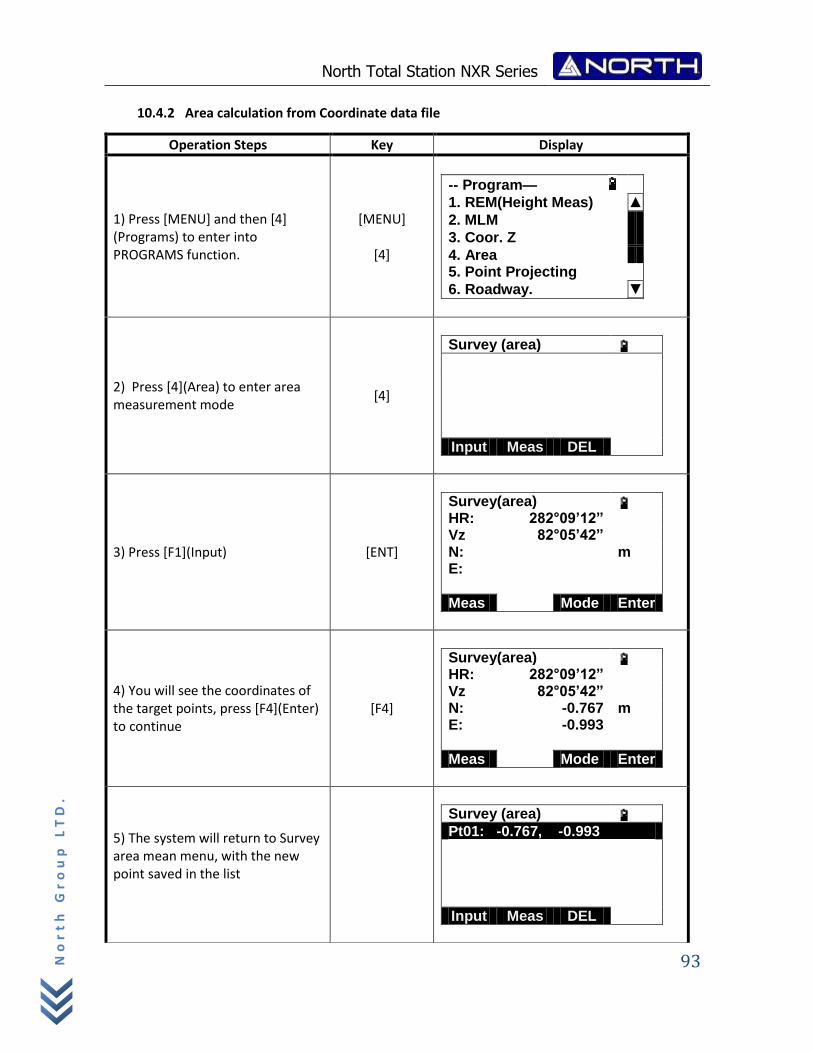
North Total Station NXR Series
93
No
rt
h G
ro
up
LT
D.
10.4.2 Area calculation from Coordinate data file
Operation Steps Key Display
1) Press [MENU] and then [4] (Programs) to enter into PROGRAMS function.
[MENU]
[4]
-- Program—
1. REM(Height Meas) ▲
2. MLM
3. Coor. Z
4. Area 5. Point Projecting
6. Roadway. ▼
2) Press [4](Area) to enter area measurement mode
[4]
Survey (area)
Input Meas DEL
3) Press [F1](Input) [ENT]
Survey(area) HR: 282°09’12” Vz 82°05’42” N: m E:
Meas Mode Enter
4) You will see the coordinates of the target points, press [F4](Enter) to continue
[F4]
Survey(area) HR: 282°09’12” Vz 82°05’42” N: -0.767 m E: -0.993
Meas Mode Enter
5) The system will return to Survey area mean menu, with the new point saved in the list
Survey (area) Pt01: -0.767, -0.993
Input Meas DEL
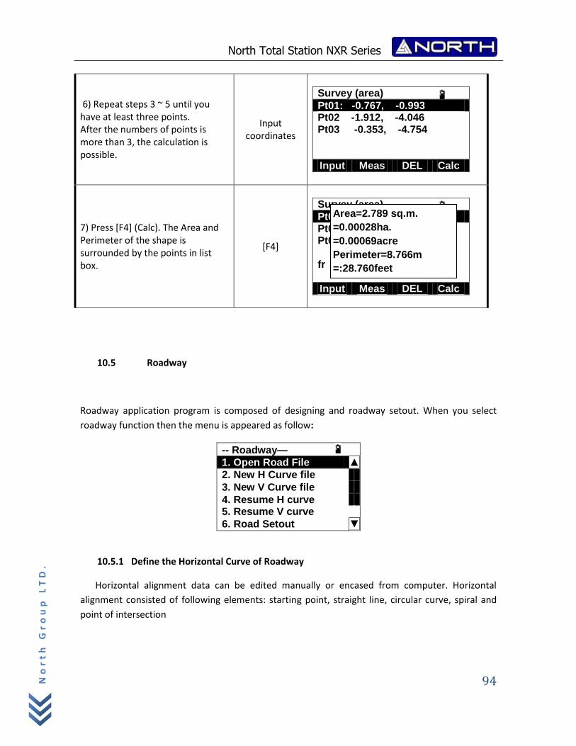
North Total Station NXR Series
94
No
rt
h G
ro
up
LT
D.
10.5 Roadway
Roadway application program is composed of designing and roadway setout. When you select
roadway function then the menu is appeared as follow:
-- Roadway—
1. Open Road File ▲
2. New H Curve file
3. New V Curve file
4. Resume H curve 5. Resume V curve
6. Road Setout ▼
10.5.1 Define the Horizontal Curve of Roadway
Horizontal alignment data can be edited manually or encased from computer. Horizontal
alignment consisted of following elements: starting point, straight line, circular curve, spiral and
point of intersection
6) Repeat steps 3 ~ 5 until you have at least three points. After the numbers of points is more than 3, the calculation is possible.
Input coordinates
Survey (area) Pt01: -0.767, -0.993 Pt02 -1.912, -4.046 Pt03 -0.353, -4.754
Input Meas DEL Calc
7) Press [F4] (Calc). The Area and Perimeter of the shape is surrounded by the points in list box.
[F4]
Survey (area) Pt01: -0.767, -0.993 Pt02 -1.912, -4.046 Pt03 -0.353, -4.754 fr
Input Meas DEL Calc
Area=2.789 sq.m.
=0.00028ha.
=0.00069acre
Perimeter=8.766m
=:28.760feet
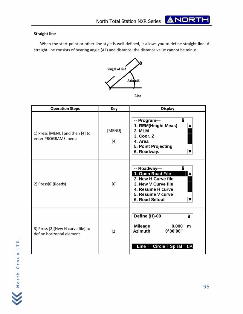
North Total Station NXR Series
95
No
rt
h G
ro
up
LT
D.
Straight line
When the start point or other line style is well‐defined, it allows you to define straight line. A
straight line consists of bearing angle (AZ) and distance; the distance value cannot be minus
Operation Steps Key Display
1) Press [MENU] and then [4] to enter PROGRAMS menu
[MENU]
[4]
-- Program—
1. REM(Height Meas) ▲
2. MLM
3. Coor. Z
4. Area 5. Point Projecting
6. Roadway. ▼
2) Press[6](Roads) [6]
-- Roadway—
1. Open Road File ▲
2. New H Curve file
3. New V Curve file
4. Resume H curve 5. Resume V curve
6. Road Setout ▼
3) Press [2](New H curve file) to define horizontal element
[2]
Define (H)-00 Mileage 0.000 m
Azimuth 0°00’00”
Line Circle Spiral I.P.
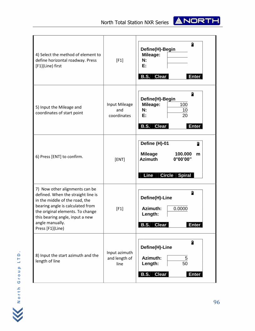
North Total Station NXR Series
96
No
rt
h G
ro
up
LT
D.
4) Select the method of element to define horizontal roadway. Press [F1](Line) first
[F1]
Define(H)-Begin
Mileage:
N:
E:
B.S. Clear Enter
5) Input the Mileage and coordinates of start point
Input Mileage and
coordinates
Define(H)-Begin
Mileage: 100
N: 10
E: 20
B.S. Clear Enter
6) Press [ENT] to confirm.
[ENT]
Define (H)-01 Mileage 100.000 m
Azimuth 0°00’00”
Line Circle Spiral I.P.
7) Now other alignments can be defined. When the straight line is in the middle of the road, the bearing angle is calculated from the original elements. To change this bearing angle, input a new angle manually. Press [F1](Line)
[F1]
Define(H)-Line
Azimuth: 0.0000
Length:
B.S. Clear Enter
8) Input the start azimuth and the length of line
Input azimuth and length of
line
Define(H)-Line
Azimuth: 5
Length: 50
B.S. Clear Enter
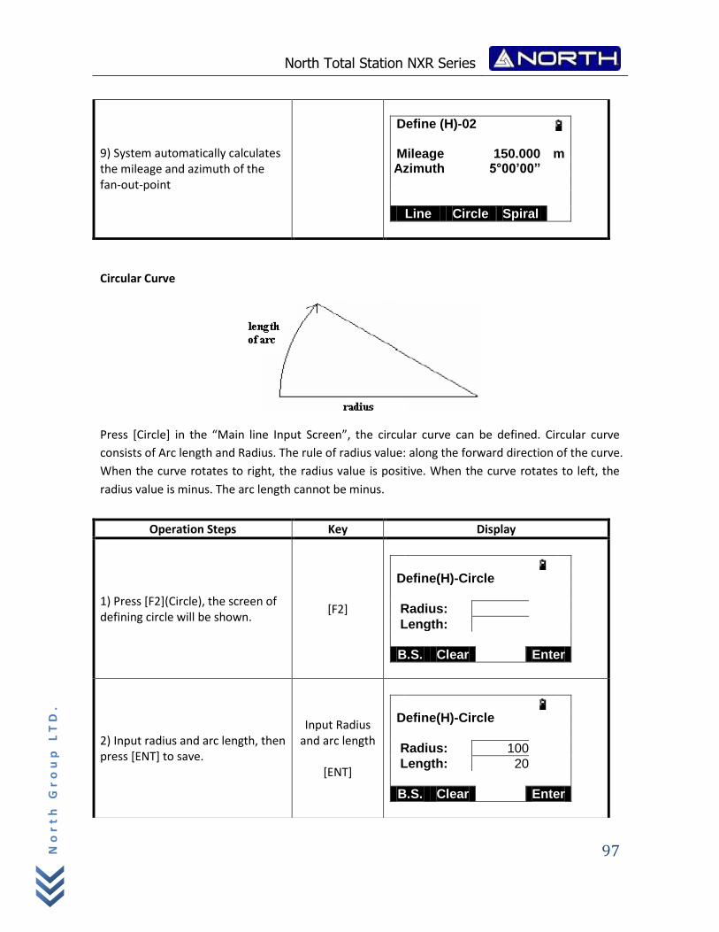
North Total Station NXR Series
97
No
rt
h G
ro
up
LT
D.
Circular Curve
Press [Circle] in the “Main line Input Screen”, the circular curve can be defined. Circular curve
consists of Arc length and Radius. The rule of radius value: along the forward direction of the curve.
When the curve rotates to right, the radius value is positive. When the curve rotates to left, the
radius value is minus. The arc length cannot be minus.
9) System automatically calculates the mileage and azimuth of the fan-out-point
Define (H)-02 Mileage 150.000 m
Azimuth 5°00’00”
Line Circle Spiral I.P.
Operation Steps Key Display
1) Press [F2](Circle), the screen of defining circle will be shown.
[F2]
Define(H)-Circle
Radius:
Length:
B.S. Clear Enter
2) Input radius and arc length, then press [ENT] to save.
Input Radius and arc length
[ENT]
Define(H)-Circle
Radius: 100
Length: 20
B.S. Clear Enter
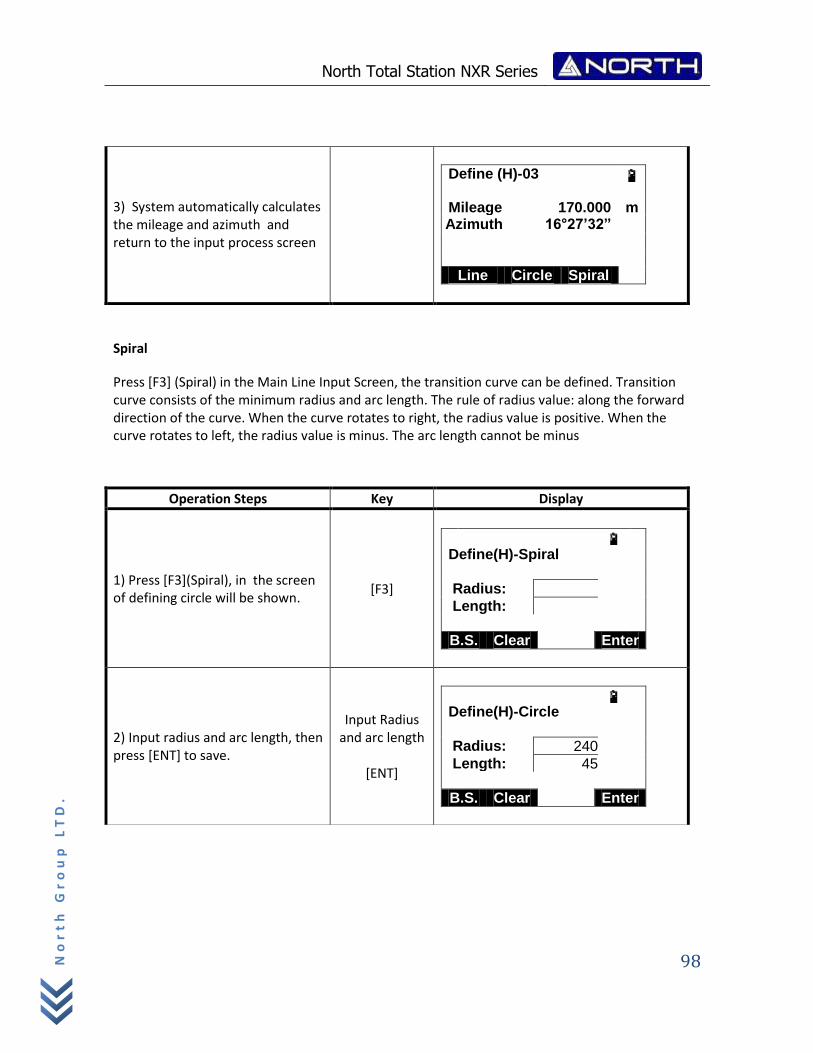
North Total Station NXR Series
98
No
rt
h G
ro
up
LT
D.
Spiral
Press [F3] (Spiral) in the Main Line Input Screen, the transition curve can be defined. Transition curve consists of the minimum radius and arc length. The rule of radius value: along the forward direction of the curve. When the curve rotates to right, the radius value is positive. When the curve rotates to left, the radius value is minus. The arc length cannot be minus
3) System automatically calculates the mileage and azimuth and return to the input process screen
Define (H)-03 Mileage 170.000 m
Azimuth 16°27’32”
Line Circle Spiral I.P.
Operation Steps Key Display
1) Press [F3](Spiral), in the screen of defining circle will be shown.
[F3]
Define(H)-Spiral
Radius:
Length:
B.S. Clear Enter
2) Input radius and arc length, then press [ENT] to save.
Input Radius and arc length
[ENT]
Define(H)-Circle
Radius: 240
Length: 45
B.S. Clear Enter
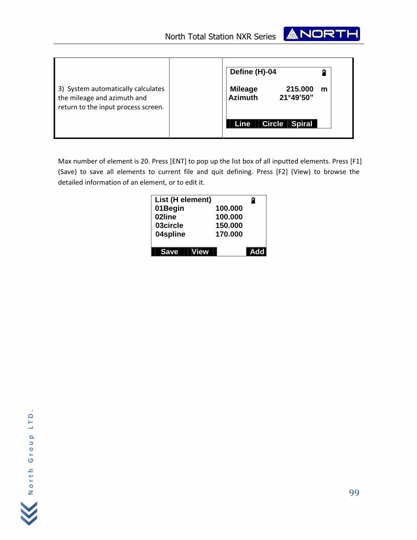
North Total Station NXR Series
99
No
rt
h G
ro
up
LT
D.
Max number of element is 20. Press [ENT] to pop up the list box of all inputted elements. Press [F1]
(Save) to save all elements to current file and quit defining. Press [F2] (View) to browse the
detailed information of an element, or to edit it.
List (H element) 01Begin 100.000 02line 100.000
03circle 150.000 04spline 170.000
Save View Add
3) System automatically calculates the mileage and azimuth and return to the input process screen.
Define (H)-04 Mileage 215.000 m
Azimuth 21°49’50”
Line Circle Spiral I.P.
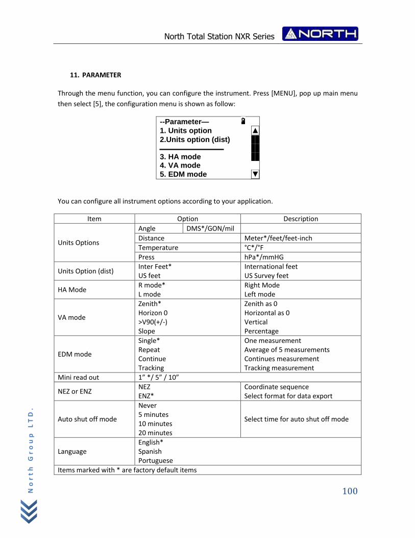
North Total Station NXR Series
100
No
rt
h G
ro
up
LT
D.
11. PARAMETER Through the menu function, you can configure the instrument. Press [MENU], pop up main menu
then select [5], the configuration menu is shown as follow:
--Parameter—
1. Units option ▲
2.Units option (dist) 3. HA mode 4. VA mode
5. EDM mode ▼
You can configure all instrument options according to your application.
Item Option Description
Units Options
Angle DMS*/GON/mil
Distance Meter*/feet/feet-inch
Temperature °C*/°F
Press hPa*/mmHG
Units Option (dist) Inter Feet* US feet
International feet US Survey feet
HA Mode R mode* L mode
Right Mode Left mode
VA mode
Zenith* Horizon 0 >V90(+/-) Slope
Zenith as 0 Horizontal as 0 Vertical Percentage
EDM mode
Single* Repeat Continue Tracking
One measurement Average of 5 measurements Continues measurement Tracking measurement
Mini read out 1” */ 5” / 10”
NEZ or ENZ NEZ ENZ*
Coordinate sequence Select format for data export
Auto shut off mode
Never 5 minutes 10 minutes 20 minutes
Select time for auto shut off mode
Language English* Spanish Portuguese
Items marked with * are factory default items
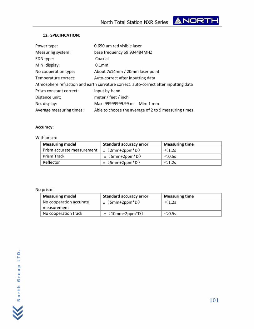
North Total Station NXR Series
101
No
rt
h G
ro
up
LT
D.
12. SPECIFICATION:
Power type: 0.690 um red visible laser
Measuring system: base frequency 59.934484MHZ
EDN type: Coaxial
MINI display: 0.1mm
No cooperation type: About 7x14mm / 20mm laser point
Temperature correct: Auto-correct after inputting data
Atmosphere refraction and earth curvature correct: auto-correct after inputting data
Prism constant correct: Input by-hand
Distance unit: meter / feet / inch
No. display: Max: 99999999.99 m Min: 1 mm
Average measuring times: Able to choose the average of 2 to 9 measuring times
Accuracy:
With prism:
Measuring model Standard accuracy error Measuring time
Prism accurate measurement ±(2mm+2ppm*D) <1.2s
Prism Track ±(5mm+2ppm*D) <0.5s
Reflector ±(5mm+2ppm*D) <1.2s
No prism:
Measuring model Standard accuracy error Measuring time
No cooperation accurate measurement
±(5mm+2ppm*D) <1.2s
No cooperation track ±(10mm+2ppm*D) <0.5s
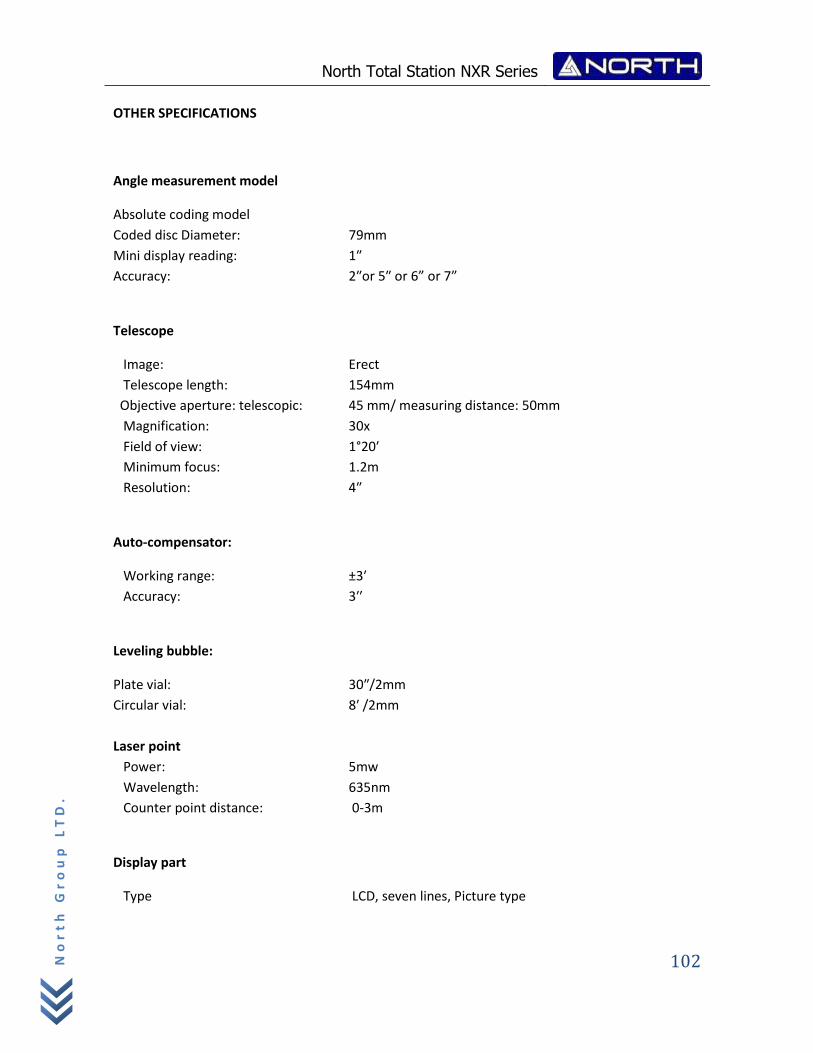
North Total Station NXR Series
102
No
rt
h G
ro
up
LT
D.
OTHER SPECIFICATIONS
Angle measurement model
Absolute coding model
Coded disc Diameter: 79mm
Mini display reading: 1″
Accuracy: 2″or 5″ or 6” or 7”
Telescope
Image: Erect
Telescope length: 154mm
Objective aperture: telescopic: 45 mm/ measuring distance: 50mm
Magnification: 30x
Field of view: 1°20′
Minimum focus: 1.2m
Resolution: 4″
Auto-compensator:
Working range: ±3′
Accuracy: 3′′
Leveling bubble:
Plate vial: 30″/2mm
Circular vial: 8′ /2mm
Laser point
Power: 5mw
Wavelength: 635nm
Counter point distance: 0-3m
Display part
Type LCD, seven lines, Picture type
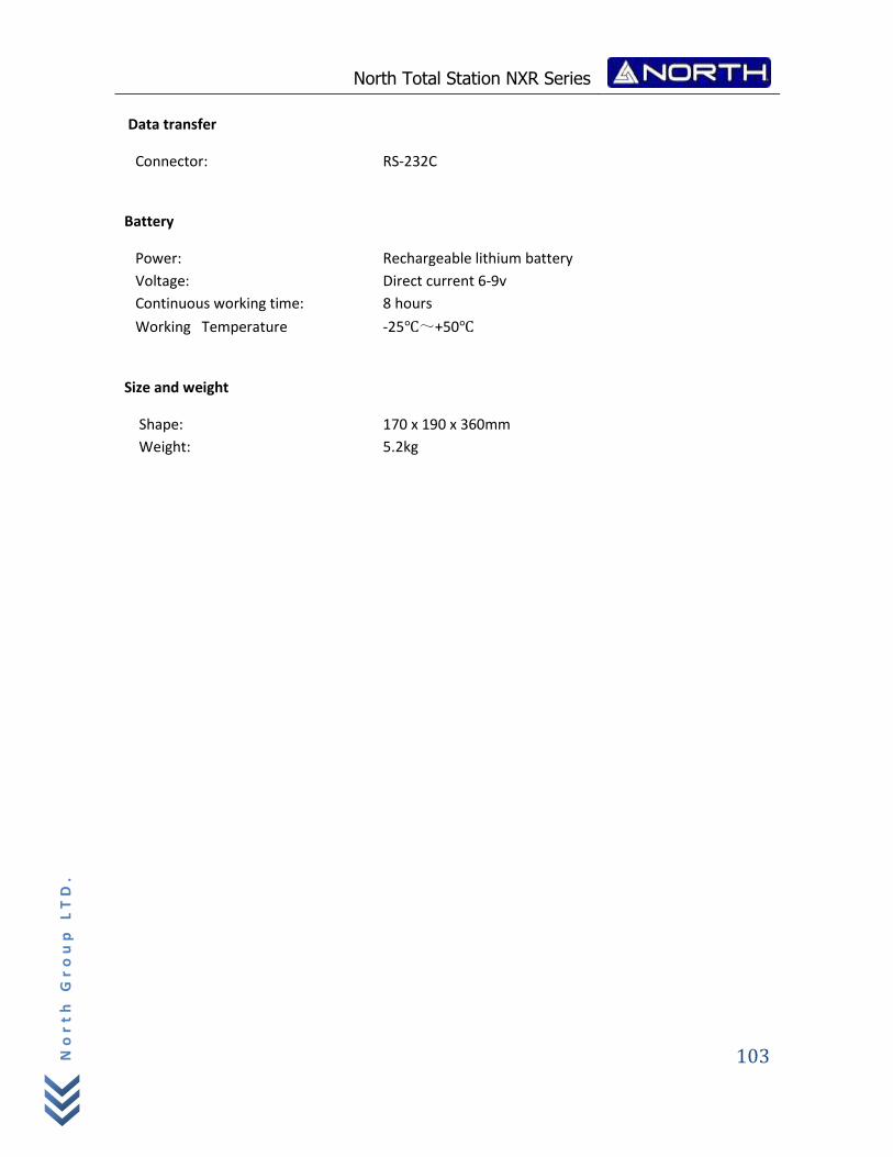
North Total Station NXR Series
103
No
rt
h G
ro
up
LT
D.
Data transfer
Connector: RS-232C
Battery
Power: Rechargeable lithium battery
Voltage: Direct current 6-9v
Continuous working time: 8 hours
Working Temperature -25℃~+50℃
Size and weight
Shape: 170 x 190 x 360mm
Weight: 5.2kg
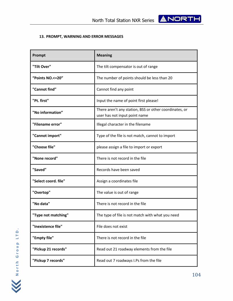
North Total Station NXR Series
104
No
rt
h G
ro
up
LT
D.
13. PROMPT, WARNING AND ERROR MESSAGES
Prompt Meaning
"Tilt Over" The tilt compensator is out of range
“Points NO.<=20” The number of points should be less than 20
"Cannot find" Cannot find any point
"Pt. first" Input the name of point first please!
"No information” There aren’t any station, BSS or other coordinates, or
user has not input point name
"Filename error" Illegal character in the filename
"Cannot import" Type of the file is not match, cannot to import
"Choose file" please assign a file to import or export
"None record" There is not record in the file
"Saved" Records have been saved
"Select coord. file" Assign a coordinates file
"Overtop" The value is out of range
"No data" There is not record in the file
"Type not matching" The type of file is not match with what you need
"Inexistence file" File does not exist
"Empty file" There is not record in the file
"Pickup 21 records" Read out 21 roadway elements from the file
"Pickup 7 records" Read out 7 roadways I.Ps from the file
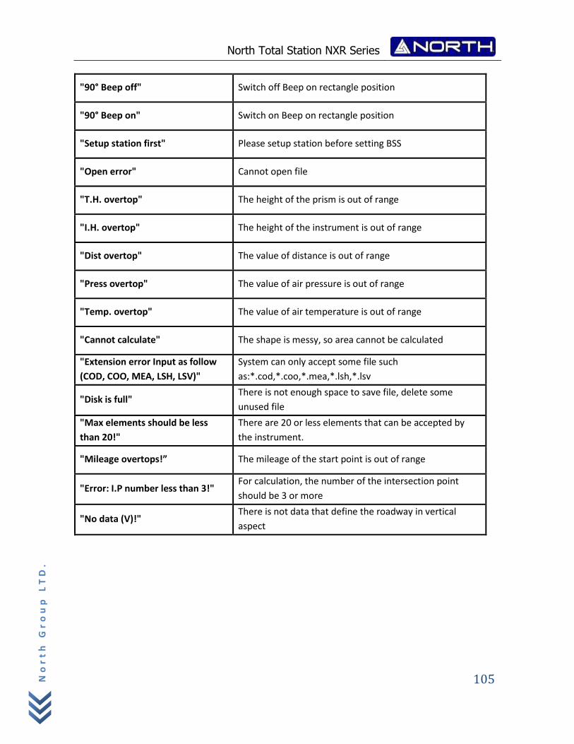
North Total Station NXR Series
105
No
rt
h G
ro
up
LT
D.
"90° Beep off" Switch off Beep on rectangle position
"90° Beep on" Switch on Beep on rectangle position
"Setup station first" Please setup station before setting BSS
"Open error" Cannot open file
"T.H. overtop" The height of the prism is out of range
"I.H. overtop" The height of the instrument is out of range
"Dist overtop" The value of distance is out of range
"Press overtop" The value of air pressure is out of range
"Temp. overtop" The value of air temperature is out of range
"Cannot calculate" The shape is messy, so area cannot be calculated
"Extension error Input as follow
(COD, COO, MEA, LSH, LSV)"
System can only accept some file such
as:*.cod,*.coo,*.mea,*.lsh,*.lsv
"Disk is full" There is not enough space to save file, delete some
unused file
"Max elements should be less
than 20!"
There are 20 or less elements that can be accepted by
the instrument.
"Mileage overtops!” The mileage of the start point is out of range
"Error: I.P number less than 3!" For calculation, the number of the intersection point
should be 3 or more
"No data (V)!" There is not data that define the roadway in vertical
aspect
North Total Station NXR Series
106
No
rt
h G
ro
up
LT
D.
Information/Sales:
Technical Support:
Copyright 2007-2012 North. © 2007 North Group LTD. All rights reserved.

North Total Station NXR Series
107
No
rt
h G
ro
up
LT
D.