nonstructural examples: earthquake damage and · pdf filenonstructural examples: earthquake...
TRANSCRIPT

[!] NONSTRUCTURAL EXAMPLES: EARTHQUAKE DAMAGE AND
UPGRADE DETAILS This chapter includes specific examples of selected non structural items. In most cases, the example includes a photograph of earthquake damage that occurred to an unanchored or inadequately anchored item paired with a drawing of suggested upgrade details that can be used to reduce the seismic vulnerability of the item. Some of these are simple, generic details that can be installed by a handyman; these details are marked Do-It-Yourself. Others are schematic details that need to be developed by a design professional for a particular situation and in some instances will require installation by a specialty contractor; these details are marked Engineering Required. Enough examples have been provided to allow for an effective initial survey of most ordinaryoccupancy buildings. The end of this chapter includes installation guidelines to accompany the Do-It-Yourself details.
NONSTRUCTURAL EXAMPLES Photos of earthquake damage and suggested upgrade details are presented for a variety of common nonstructural items. While these examples do not cover every case, many items not included here would be damaged and/or upgraded in a manner similar to one that is shown. For example, the detail shown for an air compressor is applicable to many pieces of mechanical or HV AC equipment that are mounted on vibration isolation springs. Similarly, the wall and floor anchorage details shown for tall shelving or file cabinets are applicable to other items, such as storage cabinets or personnel lockers. The detail shown for a fire extinguisher could also be applied to a fire hose cabinet. Many types of desktop or
countertop equipment found in offices, hospitals, or laboratories could be restrained by using the suggestions for desktop computers, although special detailing may be warranted for expensive equipment. Seismic protection schemes for newly installed items are often similar to the anchorage or restraint details shown.
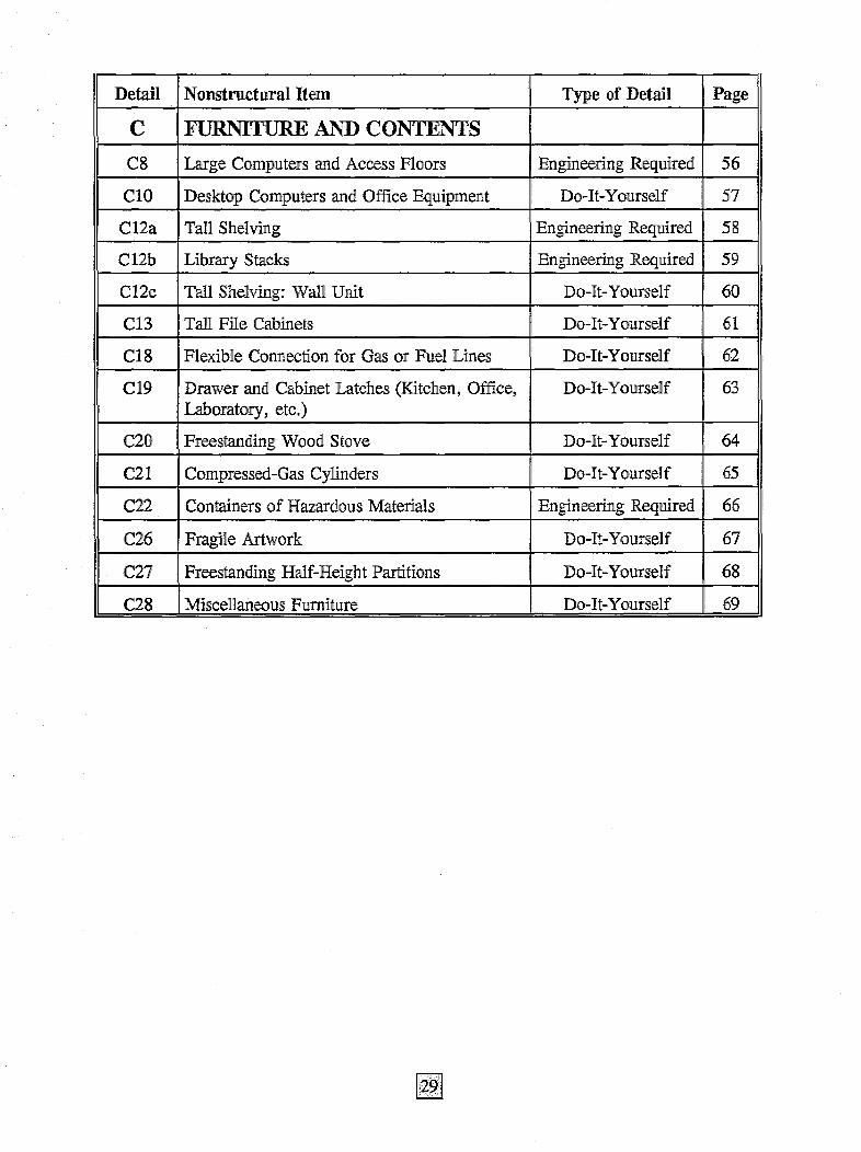
The examples have been divided into three categories: utility systems that are part of the building; built-in architectural components; and furniture and contents, which are typically the property of the occupants or tenants rather than a permanent part of the building. The examples are listed in Figure 8.
Earlhquake Damage The photographs presented here cover a variety of situations and have been taken over a 25-year period. Photographs from the 1971 San Fernando earthquake generally show damage to. items that were not restrained, while some of the more recent photographs depict damage to items that appeared to be braced or anchored but whose bracing and anchoring details were apparently inadequate to resist the severity of the shaking.
Upgrade Details The examples presented in this chapter show representative details for protecting common items from earthquake damage. The two different types of details are described below.
• Do-It-Yourself These are simple, generic details for typical non structural items. Enough information is provided that a handyman can install them using common tools and readily

available materials. Most of the examples for furniture and contents include simple details that are marked Do-It-Yourself. These details are applicable for many common items found in the horne, office, or small business. At the end of ilhls chapter are guidelines on the proper use and installation of these details.
• Engineering Required These are schematic details showing common solutions for the items in question. These sketches do not contain sufficient information for installation; they are provided primarily as an illustration of the required scope of work. The designation Engine,ering Required has been used for items where the self-help approach is most likely to be ineffective. The recommendation of this guide is that design professionals be retained to evaluate the vu]nerability of these items and design appropriate anchorage or restraint details, particularly where safety is an issue. As stated earUer, this recommendation may apply to all items in specialized facil:i.ties such as hospitals and emergency operations or communications ,centers, where interruption or loss of function is unacceptable.
Recent experience has shown many instances where fire sprinkler and! other water lines, HVAC equipment, emergency generators, water tanks, ceilings, parapets, glazing, and so on were damaged when subjected to severe shaking and failed to perform as expected. The lesson learned from this experience is that the protection of many items, particularly building utilities and architectural components in
facilities that are expected to remain functional during and! after a major earthquake, is a complex undertaking that should! be ad!dressed by engineers and ,architects with specific expertise in this area. Asa result, most building utility systems and architectur.all components have been given the designation Engineering Required. Several of the items listed under furniture and contents have also been given this designation.
The upgrade details for these items, are schematic only and are pr,esented here with estimated installation costs" primarily for planning andlor budgeting purposes.. Facilities personnel can use this information in conjunction with the survey forms and checklists induded in this guide to estimate the scope of the work needed and obtain initial cost estimates for planning purposes.
Upgrade Cost The cos.t estimates provided with the details in this chapter may be used as a rough guide for planning or bud!geting purposes .. The values ar,e intended to cover the costs of materials and labor. They do not include., any allowance for architectural or engineering fees, permits, special inspection" etc. These estimated costs represent a professional opinion based on information available at the time of publication in 1994. Actual construction costs may vary significantly, depend!ing on the timing of construction" changes in conditions, the availability of materials, regional cost variations, and other factors.

Figure 8 : N onstructural Examples
Detail Nonstructural Item Type of Detail Page
U BUILDING UTILITY SYSTEMS
U2 Batteries and Battery Rack Engineering Required 30
U3 Diesel Fuel Tank Engineering Required 31
U8 Electrical Bus Ducts and Primary Cable Engineering" Required 32 System
UlO Fire Extinguisher and Cabinet Do-It -Yourself 33
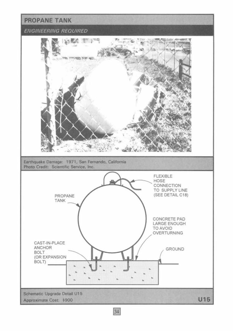
U15 Propane Tank Engineering Required 34
U19a Water Heater: Corner Installation Do-It-Yourself 35
U19b Water Heater: Wall Installation Do-It-Yourself 36
U21 Piping Engineering Required 37
U29 Chiller Engineering Required 38
U32 Air Compressor (or other HVAC Equipment) Engineering Required 40
U35 Suspended Space Heater Engineering Required 41
U36 HV AC Distribution Ducts Engineering Required 42
U37 Air Diffuser Do-It -Yourself 43
U38 Residential Chimney Engineering Required 44
A ARCIllTECTURAL ELEMENTS
A2a Built-In Partial-Height Partitions Engineering Required 45
A2b Built-In Full-Height Partitions Engineering Required 46
A3 Suspended T -Bar Ceilings Engineering Required 47
A5a Suspended Light Fixtures Do-It-Yourself 48
A5b Pendant Light Fixtures Do-It-Yourself 49
A9 Stairways Engineering Required 50
A12 Windows Engineering Required 51
A15a Unrein forced Brick Parapets Engineering Required 52
A15b Veneer Engineering Required 53
A16 Freestanding Walls or Fences Engineering Required 54
A21 Exterior Signs Engineering Required 55
Detail NonstructuraI Item Type of Detail Page ,
C FURNITURE AND CONTENTS
C8 Large Computers and Access Floors Engineering Required 56 ;
ClO Desktop Computers and Office Equipment I
Do-It -Yourself 57 I
Cl2a TaIl Shelving Engineering Required 58
C12b Library Stacks Engineering Required 59
C12c Tall Shelving: WaH Unit Do-It-Yourself 60
C13 Tall File Cabinets Do-It-Yourself 61 I
: I
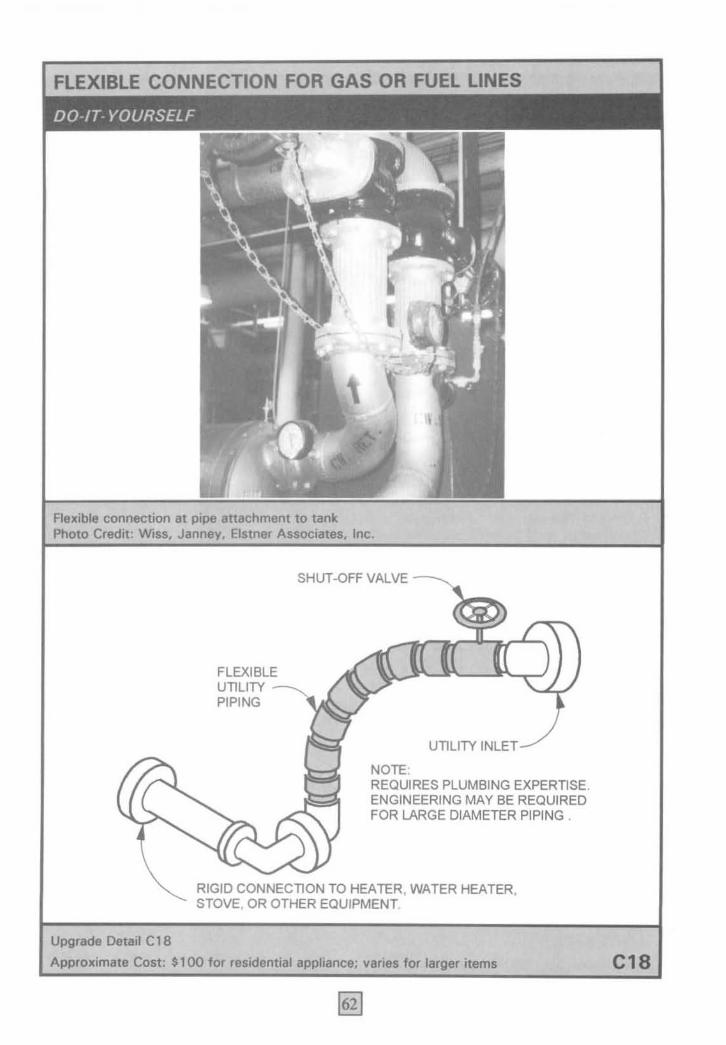
Cl8 Flexible Connection for Gas or Fuel Lines Do-It-Yourself 62 I
! C19 : Drawer and! Cabinet Latches (Kitchen, Office, Do-It-Yourself 63 1
Laboratory, ,etc.) i
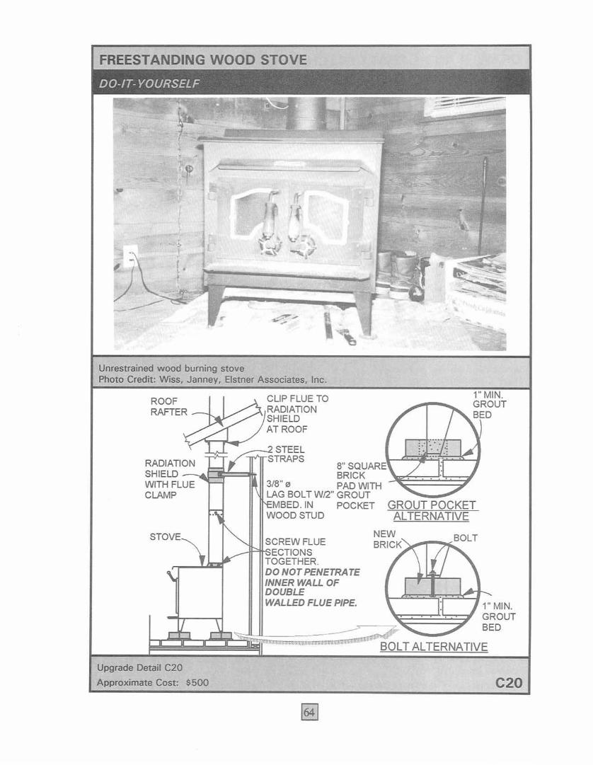
, C20 Freestanding Wood Stov,e Do-It -Yourself 64
i
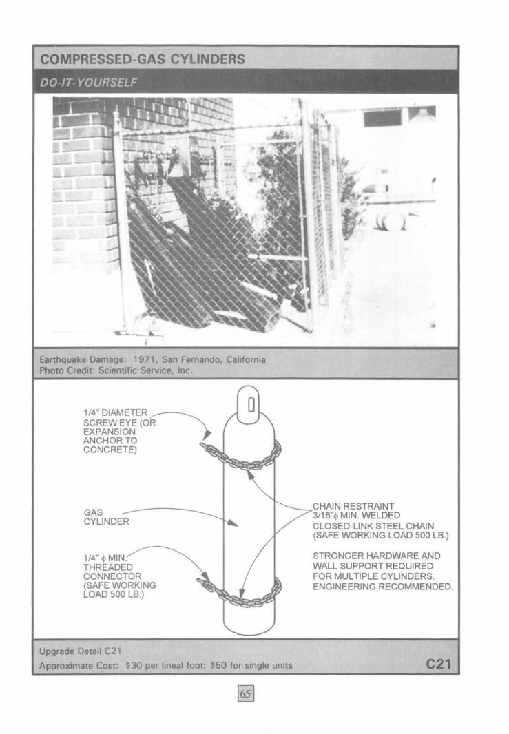
C21 Compressed-Gas Cylinders I Do-U-Yourself I
65
C22 Containers of Hazardous Materials Engineering Required 66 ;
i
C26 Fragile Artwork ~I Do-It-Yourself 67
C27 I Freestanding Half-Height Partitions Do-It-Yourself 68 I
C28 i Miscellaneous Furniture Do-It-Yourself I 69 !
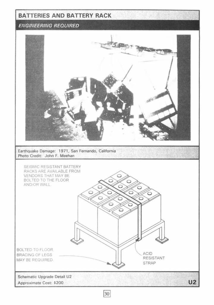
BATTERIES AND BATTERY RACK
Earthquake Damage: 1971, San Fernando, California Photo Credit: John F. Meehan
SEISMIC RESISTANT BATTERY RACKS ARE AVAILABLE FROM VENDORS THAT MAY BE BOLTED TO THE FLOOR AND'OR WALL
BOLTED ~.) FLOOR BRACING OF LEGS MAY BE REQUIRED
Schematic Upgrade Detail U2
Approximate Cost: $200
ACID RESISTANT STRAP
U2
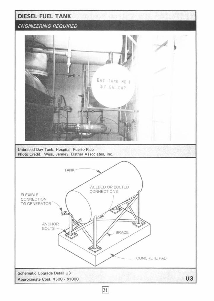
Unbraced Day Tank , Hospital, Puerto Rico Photo Credit : Wiss, Janney, Elstner Associates, Inc .
FLEXIBLE CONNECTION TO GENERATOR
ANCHOR BOLTS
TANK
Schematic Upgrade Detail U3
Approximate Cost: $500 - $1000
WELDED OR SOL TED CONNECTIONS
J
BRACE
CONCRETE PAD
U3
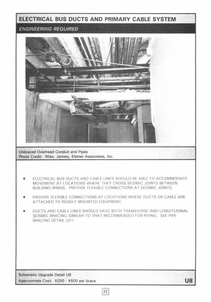
ELECTRICAL BUS DUCTS AND PRIMARY CABLE SYSTEM
Unbraced Overhead Conduit and Pipes Photo Credit: Eistner Associates, Inc.
• ELECTRICAL BUS DUCTS AND CABLE LINES SHOULD BE ABLE TO ACCOMMODATE MOVEMENT AT LOCATIONS WHERE THEY CROSS SEISMIC JOINTS BETWEEN BUILDING WINGS. PROVlOE FLEXIBLE CONNECTIONS AT SEISMIC JOI NTS.
• PROVIDE FLEXIBLE CONNECTIONS AT LOCATIONS WHERE DUCTS OR CABLE ARE ATTACHED TO RIGIDLY MOUNTED EOUIPMENT
• DUCTS AND CABLE LINES SHOULD HAVE BOTH TRANSVERSE AND LONGITUDINAL SEISMIC BRACING SIMILAR TO THAT RECOMMENDED FOR PIPING SEE PIPE BRACING DETAIL U2 1.
Schematic Upgrade Detail ua Approximate Cost: $200 - $500 per brace U8

FIRE EXTINGUISHER AND CABINET
Unrestrained Extinguisher Photo Credit: Wiss, Janney, Eistner Associates, Inc.
LATCH ON DOOR MUST NOT LOCK
UNLESS GLASS CAN BE EASIL Y
BROKEN FOR ACCESS.
Upgrade Detail U 1 0
Approximate Cost: $300
_--- GOOD LOCATION FOR FLASHLIGHT
CABINET BOLTED
~-~~WALL
STUD
QUICKRELEASE
STRAP
U10
EarIIIquoIte~: 1971. Son _. Cel_
PROPANE TANK
CAST-IN-PLACE ANCHOR BOLT
FLEXIBLE HOSE CONNECTION TO SUPPLY LINE (SEE DETAIL C1B)
CONCRETE PAD LARGE ENOUGH TO AVOID OVERTURNING
GROUND
(OREX_P_AN_S_I_O~Nr-:-~~=r~ __ ~~~~~ ____ 11 ____ _ BOLT) • •
•
_ Upo'- DetaIl U15
Approximate Coli: $900
• • • •
• • •
• • •
U16

• WATER HEATER: CORNER INSTALLATION
FIRST STUD NOT BEHIND HEATER
12" MAX. 1"MIN. FROM COMBUSTIBLE MATERIAL, TY'PICAl
WATER ~ --.H'-----+-I-HEATER 1/4" I} X 3" LAG
ENCIRCLE TANK ONE FULL ""'~"- SCREW WfF' r ---WRAP FROM FRONT AND BACK WiTH PLUMBER'S TAPE (4 PiECES TOTAL)
3/4" X 24 GAUGE PLUMBER'S TAPE (PERFORATED METAL STRAP)
PLAN
-0 •• _ • .'. e" .' •• , •
WATER HEATER
.. . . . . . "
"... ' ••• " •.• : •• • I I
WASHER
FLEXI BlE WATER CONNECTIONS
1/4" ~ EXP. ANCHORS
CONCRETE OR MASONRY WALL
WI 2" MIN. .----EMBEDMENT
FLEXIBLE GAS CONNECTION

114" o x 3" LAG SCREW WOOD WIFLAT STUD
PLAN qWWASHER-
FLATTENED
CONCRETE 114" 0 EXP. ANCHOR W12" MIN. EMBEDMENT 7?
OR MASONRY
FLEXIBLE WATER I .CONNECTION
I.
3/4" X 24 GAUGE PLUMBER'S TAPE
WATER HEATER
FLEXIBLE
36
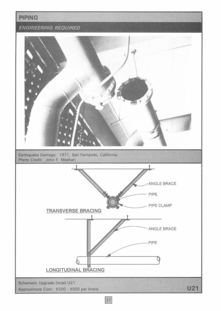
, Earthquake Damage: 1971. San Fernando. California Photo Credit: John F. Meehan
TRANSVERSE BRACING
c
.,._~ ANGLE BRACE
~--PIPE
.~ ___ PIPE CLAMP
~~--------ANGLEBRACE
LONGITUDINAL BRACING
Schematic Upgrade Detail U21
Approximate Cost: $200 - $500 per brace
~ __ PIPE
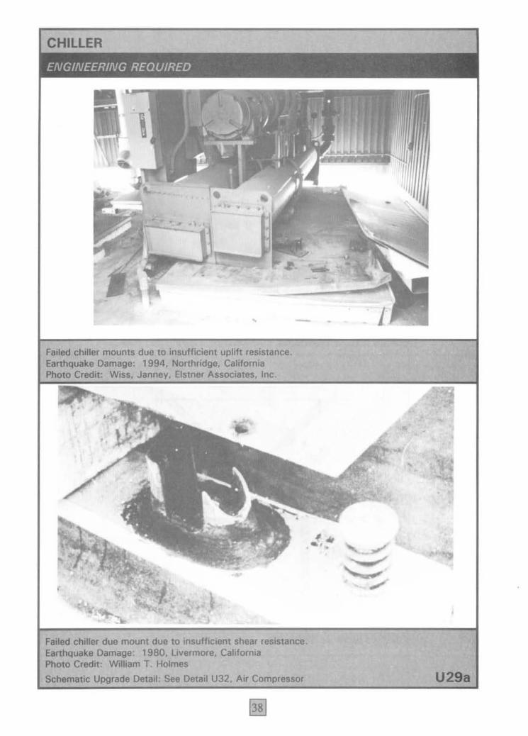
Failed chiller mounts due to insufficient uplift resistance. Earthquake Damage: 1994, Northridge. Califomia Photo Credit: Wiss. • Elstn.r Associates. Inc.
/., ... ..
,
Failed chilLer due mount due to insufficient shear resistance. Earthquake Damage: 1980. Livermore. California Photo Credit: William T. Holmes
Schematic Upgrade Detail: See Detail U32. Air Compressor U29a
I
•
•
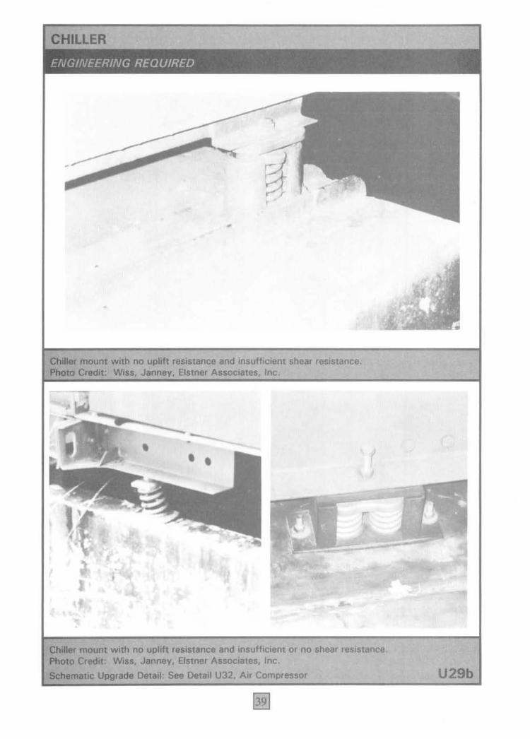
mount with no uplift resistance and insufficient shear resistance. Credit: Elstner Inc.
, . ,
• •
mount with no uplift resistance and insufficient or no shear resistance. Credit: Wiss. Janney, Bstner Associates. Inc.
Detail: See Detail U32. Air Compressor U29b

COMPRESSOR (OR OTHER HVAC
- n w
1994, CoIIfomi. _ Inc.
SUFFICIENT GAPS TO AllOW , ..... ~ HVAC EQUIPMENT SPRINGS TO ISOLATE EQUIPMENT
VIBRATlON UNDER NORMAL USE
TWO STEEL Z's OR OTHER RESTRAINTS ON EACH OF TlHE FOUR SIDES TO PREVENT UPWARD AND LATERAL EARTHQUAKE MOTION
Upgnodo DetIiI U32
NEOPRENE t:...-- "BUMPER"
PADS
ANCHOR BOLTS
SPRING MOUNT (CHECK WlTH VENDOR FOR SEISMIC MODEL)
NOTE; SPECIAL CARE SHOULD BE EXERCISED DURING DESIGN AS MANY RECENT FAilURES HAVE BEEN OBSERVED.
Coat: Dependa an individual .... ; .300 - .1 ,200
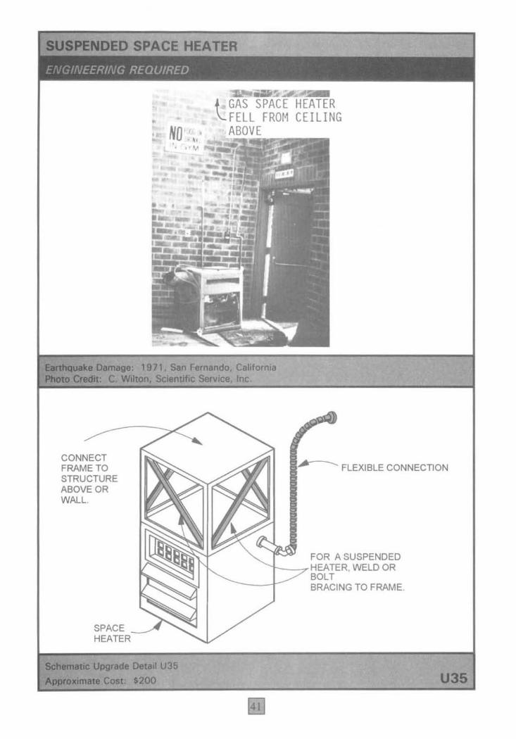
CONNECT FRAME TO STRUCTURE ABOVE OR WALL.
SPACE HEATER
.• ~ "L-. ,,,4\:.
. . ". "'"
•
""~"'''~' ',It -'''''''- ......
~o " • • 'v
l GAS ~~t~HE~AT!!I!ER FELL FROM CEILING ABO V
FLEXIBLE CONNECTION
FOR A SUSPENDED r---rHE-' WELD OR
BRACING TO FRAME.
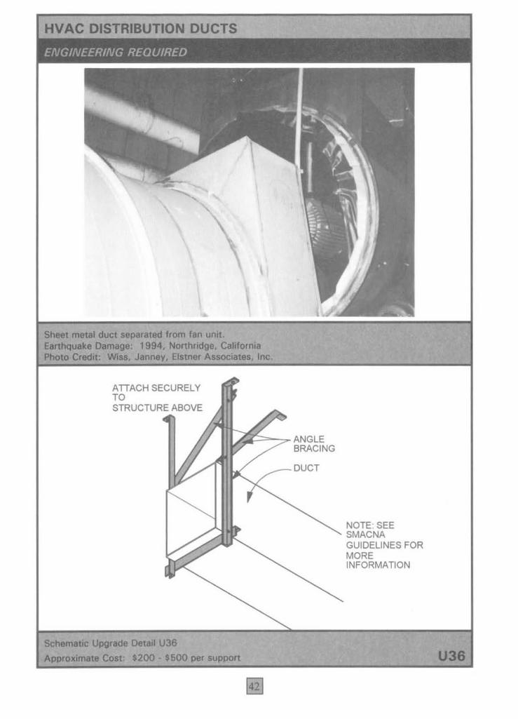
DISTRIBUTION DUCTS
-from "'" unk. Northridge, CalWomi.
Janney, EJatnor
ATTACH SECURELY TO STRUCTURE ABOVE
D,~~7" ANGLE BRACING
~DeIaIIU38 $200 - $600
DUCT
NOTE: SEE SMACNA GUIDELINES FOR MORE INFORMATION
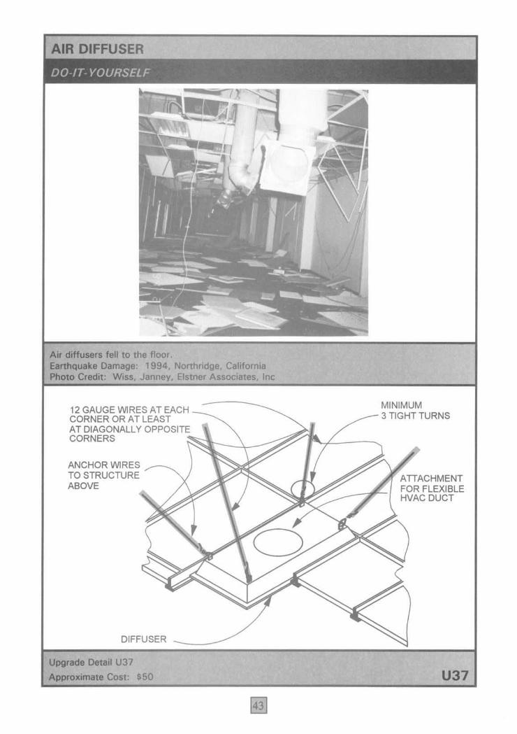
All dIIfusers fell to the floor. Damage: 1994. Northridge. California
Eistner Inc
12 GAUGE WIRES AT EACH CORNER OR ATLEAST AT DIAGONALLY OPPOSITE CORNERS
ANCHOR WIRES ___ ___ TO STRUCTURE ABOVE
DIFFUSER
Upgrodo Detail U37 Approximate Cost: $50
MINIMUM 3 TIGHT TURNS
ATTACHMENT FOR FLEXIBLE HVAC DUCT
U37
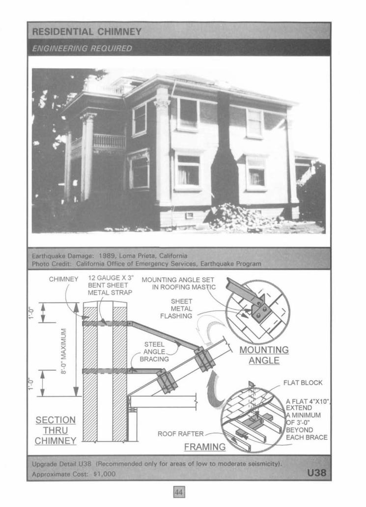
RESIDENTIAL CHIMNEY
CHIMNEY 12 GAUGE X 3" MOUNllNG ANGLE SET
SECTION THRU
CHIMNEY
BENT SHEET IN ROOFING MAS IC METAL STRAP
SHEET METAL
FLASHING
ROOF RAFTER ~~O'i;
Upgrado Detail U38 (Recommended only lor "' ... 01 low to moderate oeIamlc:ttyl. Al>!l<oximate Coat: $1 .000
FLAT BLOCK
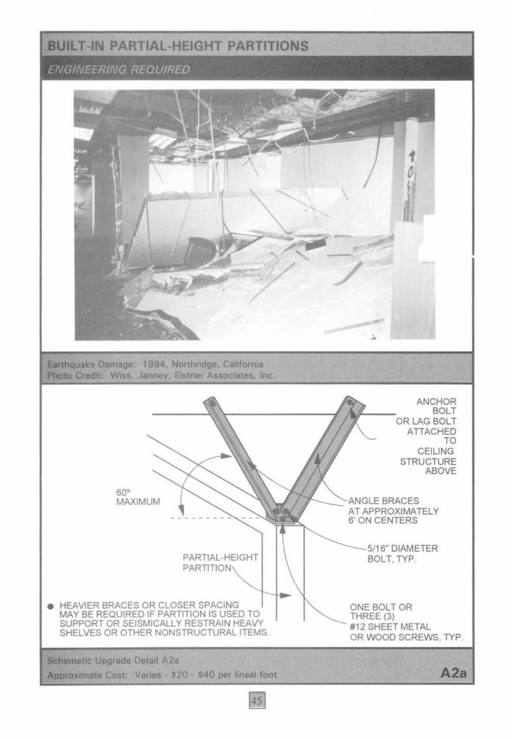
PARTIAL-HEIGHT PARTITIONS
~: 1994, Northridge, California W ... , Janney. Elatner Associ81:ea, Inc.
60' MAXIMUM
PARTIAL-HEIGHT I
• HEAVlER BRACES OR CLOSER SPACING MAY BE REQUIRED IF PARTITION IS USED TO SUPPORT OR SEISMICALLY RESTRAIN HEAVY SHELVES OR OTHER NONSTRUCTURAL ITEMS
~DetoilA2.
COlt: Vanes .20·.40 per lineal foot
• \
/
1 o
ANCHOR BOLT
OR LAG BOLT ATIACHED
TO CEILING
STRUCTURE ABOVE
__ -2-A"GLE BRACES AT APPROXIMATELY 6' ON CENTERS
5/16" DIAMETER BOLT, TYP.
ONE BOLT OR THREE (3) #12 SHEET METAL OR WOOD SCREWS, TYP.
A2a
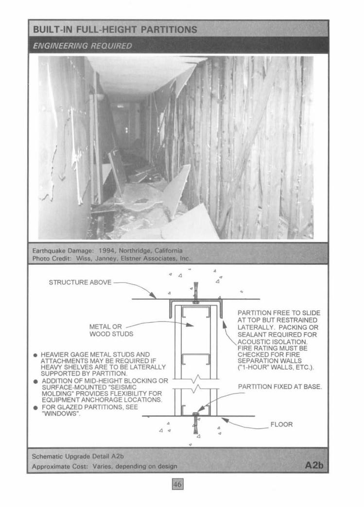
BUILT -IN FULL-HEIGHT PARTITIONS
I
Earthquake 1994. CeIIIomIa Photo Credit: E1a1f1er Inc.
-. •
• • •
I
STRUCTUREABOVE~. -I .. --...:::o~li~~1 ~[~~ .. ~I ir----:-PA~R=TlTION FREE TO SLIDE
__ --~~~ - \ATTOPBUTRESTR~NED METAL OR -- LATERALLY. PACKING OR WOOD STUDS SEALANT REQUIRED FOR
• HEAVIER GAGE METAL STUDS AND ATTACHMENTS MAY BE REQUIRED IF HEAVY SHELVES ARE TO BE LATERALLY SUPPORTED BY PARTITION
• ADDITION OF MID-HEIGHT BLOCKING OR
L
v
ACOUSTIC ISOLATION. FIRE RATING MUST BE CHECKED FOR FIRE SEPARATION WALLS ("1 -HOUR" WALLS, ETC.).
SURFACE-MOUNTED "SEISMIC ,r-VL..TT PARTITION FIXED AT BASE. MOLDING" PROVIDES FLEXIBILITY FOR v I ~ __ -EQUIPMENT ANCHORAGE LOCATIONS ...
• FOR GLAZED PARTITIONS. SEE r ..... "WlNDOWS". " I
• . - --Schematic Upgrade Detail A2b
Approximate COlt: Varles, on

SUSPENDED T -BAR CEILINGS
1994, Nonhridge, California Elstner Associates, Inc.
ANCHOR~RES TO STRUCTURE ABOVE
___ - DIAGONAL BRACING ~RES (NO. 12 GAUGE) ADJUSTABLE
APPROX. 45'
• PROVlDE 4-WAY DIAGONAL BRACING AND COMPRESSION STRUT APPROXIMATELY EVERY 12 FT. EACH WAY.
MAIN RUI~NE,R--"
ScIIomatIc Upgrede Detail A3 Coot: .60 per braee
----~ LENGTH COMPRESSION STRUT TO PREVENT VERTICAL MOVEMENT
IN
CR()SS RUNNER
A3
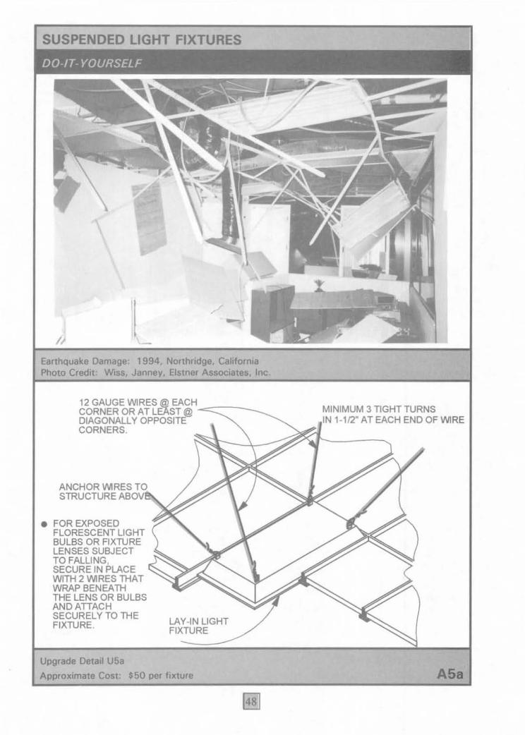
SUSPENDED LIGHT FIXTURES
Earthquake Damage: 1994, Northridge, California Photo Credit: Wlss, Eistner Associates, Inc.
12 GAUGE WlRES @ EACH,~oc-__ _ CORNER OR AT LEAST @ DIAGONALLY OPPOSITE CORNERS.
ANCHOR V'.1R.~E'BS( )ve\\. STRUCTURE '"
• FOR EXPOSED FLORESCENT LIGHT BULBS OR FIXTURE LENSES SUBJECT TO FALLING, SECURE IN PLACE WITH 2 V'.1RES THAT WRAP BENEATH THE LENS OR BULBS ANDATIACH SECURELY TO THE FIXTURE.
Upgrade Detail U5a
LAY-IN LIGHT FIXTURE
Approximate Cost: $50 per fixture
MINIMUM 3 TIGHT TURNS 1-112" AT EACH END OF WlRE
A5a

" ~( n~. , .
" • »
at Northridge Junior High School 1994. Northridge. California
ALTERNATE: RUN CABLE OUTSIDE STEM AND ATTACH TO CEILING JOIST WiTH A LAG SCREW
CEILING
BOLT TO FIXTURE
DetaU A6b Cost: $80
Research
, , :.1 r.
L. McGavin
SLACK
CABLE
HOLLOW FIXTURE PIPING
... ... .." - ,
A5b
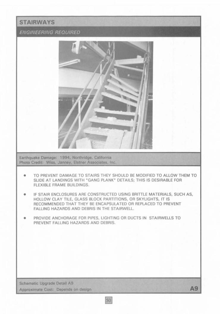
Earthquake 1994. Caltfornia Photo Credit: Inc.
• TO PREVENT DAMAGE TO STAIRS THEY SHOULD BE MODIFIED TO ALLOW THEM TO SLIDE AT LANDINGS WITH "GANG PLANK" DETAILS; THIS IS DESIRABLE FOR FLEXIBLE FRAME BUILDINGS.
• IF STAIR ENCLOSURES ARE CONSTRUCTED USING BRITTLE MATERIALS. SUCH AS. HOLLOW CLAY TILE. GLASS BlOCK PARTITIONS. OR SKYLIGHTS. IT IS RECOMMENDED THAT THEY BE ENCAPSULATED OR REPLACED TO PREVENT FALLING HAZARDS AND DEBRIS IN THE STAIRWELL.
• PROVIDE ANCHORAGE FOR PIPES. LIGHTING OR DUCTS IN STAIRWELLS TO PREVENT FALLING HAZARDS AND DEBRIS.
Schematic Upgrade Dolan A9 Approximate Cost: Depends on A9
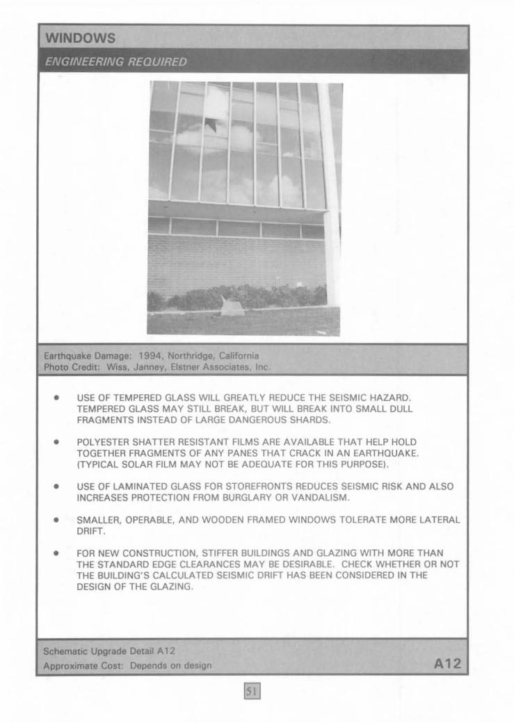
EIrthquoke Domoge: 1994. _ridge, CaIHorni.
• USE OF TEMPERED GLASS WILL GREATLY REOUCE THE SEISMIC HAZARO. TEMPEREO GLASS MAY STILL BREAK, BUT WILL BREAK INTO SMALL OULL FRAGMENTS INSTEAD OF LARGE DANGEROUS SHARDS.
• POLYESTER SHATTER RESISTANT FILMS ARE AVAILABLE THAT HELP HOLD TOGETHER FRAGMENTS OF ANY PANES THAT CRACK IN AN EARTHOUAKE. (TYPICAL SOLAR FILM MAY NOT BE ADEOUATE FOR THIS PURPOSEI .
• USE OF LAMINATED GLASS FOR STOREFRONTS REDUCES SEISMIC RISK AND ALSO INCREASES PROTECTION FROM BURGLARY OR VANDALISM .
• SMALLER, OPERABLE, AND WOODEN FRAMED WINDOWS TOLERATE MORE LATERAL DRIFT.
• FOR NEW CONSTRUCTION, STIFFER BUILDINGS AND GLAZING WITH MORE THAN THE STANDARD EDGE CLEARANCES MAY BE DESIRABLE. CHECK WHETHER OR NOT THE BUILDING'S CALCULATED SEISMIC DRIFT HAS BEEN CONSIDERED IN THE DESIGN OF THE GLAZING.
__ Upgrade IlataiI A 12
Approximate Coat: Depend. on daaign A12
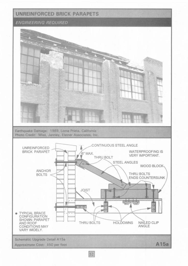
UNREIN FORCED BRICK PARAPETS
Earthquake Photo Credjt:
1989. Lome Prieta. California Eistner Inc.
CONTINUOUS STEEL ANGLE UNREINFORCED -1iF9<U"===r BRICK PARAPET 6" MAX.
ANCHOR BOL TS ~"--'
• TYPICAL BRACE CONFIGURATION SHOWN; PARAPET AND ROOF CONDITIONS MAY VARY WDELY.
Schematic Upgrade Detail A 168
Approximate Cost: $60 per foot
THRU BOLT
,=~"JOIST
THRU BOLTS
WATERPROOFING IS VERY IMPORTANT.
WOOD BLOCK
THRU BOLTS ENDS COUNTERSUNK
HOLDOWNS NAI ED CLIP ANGLE

Earthquake Damage: 1994. Northridge. Cahfornia Photo Credit: Roben Reitherman
• SEE APPLICABLE BUILDING CODE REQUIREMENTS FOR LIMITATIONS REGARDING THE HEIGHT. AREA. UNIT SIZE. AND UNIT WEIGHT OF EITHER ADHERED OR ANCHORED VENEER SVSTEMS. REFER TO THE CODE SECTIONS FOR SPECIFIC REQUIREMENTS FOR BACKING. TIES. AND REINFORCEMENT. (FOR EXAMPLE. SECTION 1403 OF THE 1994 UBC).
• VENEER SVSTEMS MUST ALSO AT LEAST MEET THE MINIMUM LATERAL FORCE REOUIREMENTS FOR NONSTRUCTURAL COMPONENTS. (FOR EXAMPLE. THE REQUIREMENTS FOR EXTERIOR AND INTERIOR ORNAMENTATION AND APPENDAGES IN CHAPTER 16 OF THE 1994 UBC).
• REMOVAL OF VENEER MOUNTED OVER ENTRANCES OR OTHER POTENTIALL V CROWDED LOCATIONS IS THE MOST RELIABLE UPGRADE SOLUTION.
Schematic Upgrade Detail A 1 5b
Approximate Cost: Varies A15b
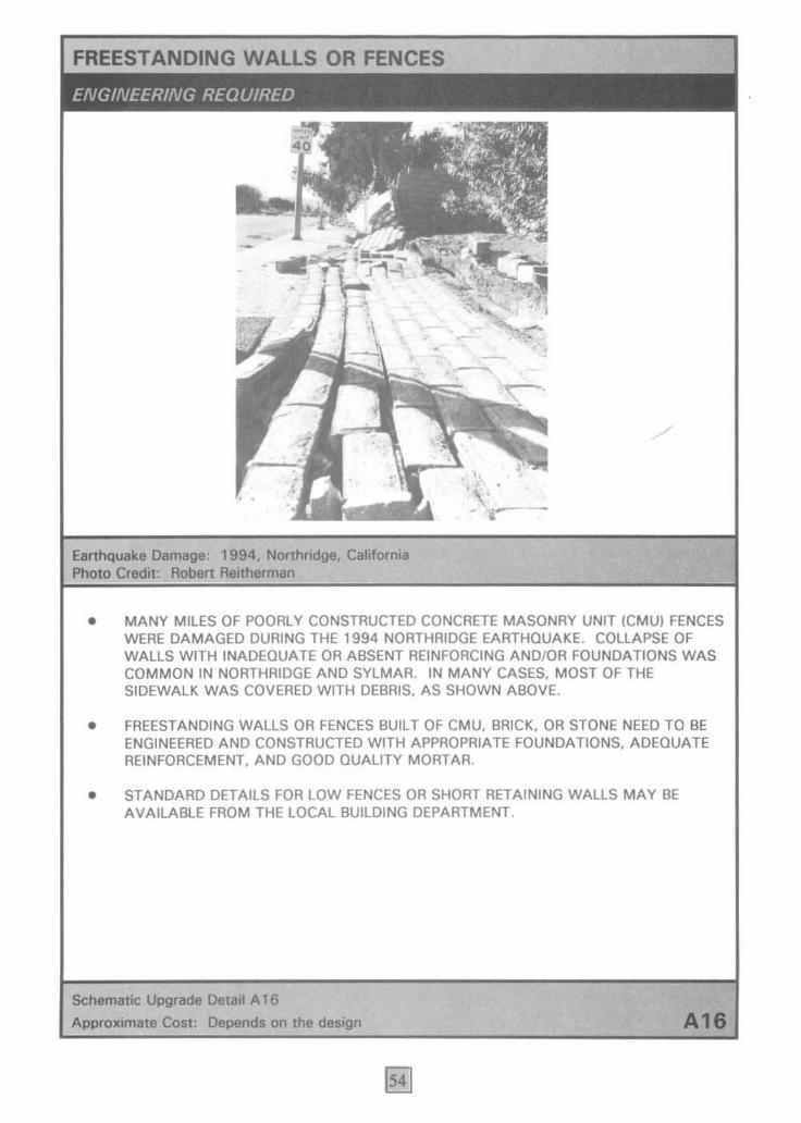
FREESTANDING WALLS DR FENCES
-.
Earthquake Damage: 1994. Nonhridge, California Photo Credit: Robert Reitherman
. /
, . I •
- i- -
• MANY MILES OF POORLY CONSTRUCTED CONCRETE MASONRY UNIT ICMU) FENCES WERE DAMAGED DURING THE 1994 NORTHRIDGE EARTHQUAKE. COLLAPSE OF WALLS WITH INADEQUATE OR ABSENT REINFORCING AND/OR FOUNDATIONS WAS COMMON IN NORTHRIDGE AND SYLMAR. IN MANY CASES, MOST OF THE SIDEWALK WAS COVERED WITH DEBRIS, AS SHOWN ABOVE.
• FREESTANDING WALLS OR FENCES BUILT OF CMU, BRICK, OR STONE NEED TO BE ENGINEERED AND CONSTRUCTED WITH APPROPRIATE FOUNDATIONS, ADEOUATE REINFORCEMENT, AND GOOD ~UALITY MORTAR.
• STANDARD DETAILS FOR LOW FENCES OR SHORT RETAINING WALLS MAY BE AVAILABLE FROM THE LOCAL BUILDING DEPARTMENT.
Schematic Upgrade Detail A 16
Approximate Cost: Depends on the design A18

, (
1979, Imperial Valley, ea-"Ia
RUSTPROOFING ESSENTIAL
Inc.
TOP STRUT, RATHER THAN CHAIN . CAN PREVENT "SEISMIC BOUNCING"
CONNECTIONS
on,.y "'~=====~=!,=,==l. ./ DIRECTLY TO ~ -- STRUCTURE.
HEAVY MARQUEE, SIGN, CANOPY
CANTILEVER BACK-UP ~~n CAPABILITY
A21

LARGE COMPUTERS AND ACCESS FLOORS
•
-
T.....,..arv bracing lor collapsed """ ... floor EanhquoIce Damage: 1994. Northridge. california Photo Crod~: Wias. Elatnor Associotos. Inc.
VARIOUS RESTRAINT SCHEMES ADVOCATED FOR CABINET'
• CASTERS TO SOMEWHAT ISOLATE COMPUTER FROM MOTION
• PRETENSED THREADED ROD FROM COMPUTER CABINET BASE THROUGH RAISED FLOOR
• TETHER CABLES
PLACE ANGLES AROUND CABLE OPENINGS TO PREVENT COMPUTER
~~====~~~~EETFROM
U FALLING INTO HOLES.
PROVlDE DIAGONAL BRACES AND BOLT PEDESTAL BASES TO CONCRETE SLAB BOLT PEDESTAL BASES TO CONCRETE SLAB (REQUIRED FOR HEAVILY LOADED FLOOR \USUALLY ADEQUATE FOR PEDESTALS UP TO
e~~6t~L~b':~~f&1~L~E?~JlgKM~J~LS • HIGH).
_ Upgrade o.tall C8 Approximate Cost: _ floor alone -- $3 - $7 per SQuare foot
Cabinet restraint ~- $ 300 - $ 500 per cabinet
56
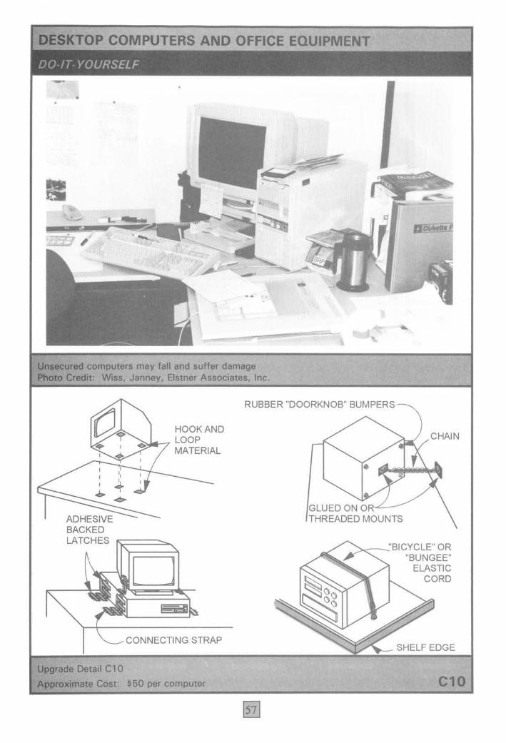
COMPUTERS AND OFFICE EQUIPMENT
•
- L
... , .;.
" . . 'r.~, ..
computerS may fall and suffer damage . WiA. Satner Associates. Inc . . \-.
HOOK AND LOOP MATERIAL
\ + ......
ADHESIVE BACKED LATCHES
CONNECTING STRAP
Coat: $50 per computer
RUBBER "DOORKNOB" BUMPERS
•
GLUED ON OR,L-/ THREADED MOUNTS
. ~~~'BICYCLE" OR "BUNGEE"
ELASTIC CORD
SHELF EDGE
C10

TALL SHELVING: FREESTANDING
NO BRACING ACROSS TOPS
?#( P f .. -- NO
r Earthquake Damage: 1972. Managua, Nicaragua Photo Credit: John F. Moo""n
STEEL ANGLE
TOP OF
SHELVI;N~GI;;;;;;;~;;;;
S'-8" MIN.
STEEL STRAP-->< CROSS BRACING.
SHELVING
UNIT TIE (STEEL STRAP WITH 1/4" • BOLTS)
Scherna1ic Upg,odo Detait e12. Approximate COlt: $20 lineal foot of shelving
•
l
I
I
BOLT ANGLE TO WALL OR STUD
NeHOR TO WALL (NOTE: TUD WAlLS NOT STRONG
ENOUGH FOR MUL nPLE ROWS OR LONG RANGES.
BOTTOM OF SHELVING UNIT
EXPANSION ANCHOR BOLT (3/QMIN. DIAMETER X 2112" MIN. EMBEDMENT)
C12a
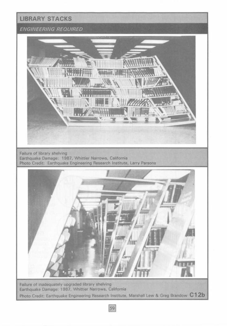
Failure of library shelving Earthquake 1987. Whittier Narrows, california Photo Credit: . Research Institute, Larry Parsons
Failure of inadequately upgraded library shelving Earthquake Damage: 1987. Whittier Narrows. California
Photo Credit: Earthquake Engineering Research Institute. Marshall Lew &
.. ,
Brandow C 12b

TALL SHELVING: WALL UNIT
, J; ~\ ~ .
. , r
• •
FaBure of inadequately upgraded shelving; toggkt bolt pulled out of gypsum board. brIhquoke Domago: 1994. Nonhridge. Cal~ornia Photo CrodIt: EI_ Associates. Inc.
BRACKE~ AT TOP OR
AT SID S BOOK CASE
114"~ x 2" WOOD SCREW (SHOWN)
OR 114" ~ MACHINE BOLT
WITH NUT & WASHER
BOOKCASE
BOOKCASE
BOOKCASE
METAL. WIRE. OR ELASTIC GUARDRAILS OR PLASTlC STRIP WILL HELP PREVENT OBJECTS FROM
---- FALLING OFF SHELVES
Upgrade Dotail e12e
Approximate Cost: $20 per lineal foot of shelving
~"""_LAG SCREW
EXTERIOR ANGLE
BRACKET
WOOD STUD
~"""r-LAG SCREW
INTERIOR ANGLE
BRACKET
IN • TYP.)
"2" CUP BRACKET
WOOD STUD
C12c

. ,1\ ) . ..........
E.rthquake Damage: 1994. Califomia Photo Credit: Wi... EI_ Inc.
ANGLE USED TO FASTEN UNITS TO~ WALL STUD 2- 1/4", BOLTS OR 1----~:5<~ 1/4" . LAG SCREWS WITH 2" MIN . .c ....... EMBEDMENT IN ...... """ WOOD STUD •
~. FOR FREE-STANDING UNITS. FASTEN CONTINUOUS ANGLE TO UNITS AND FLOOR
Upgrade Detail e13
Approximate Cost: $20 per lineal foot
•
TOP CONNECTIONS TO TIE UNITS
TOGETHER TO FORM A MORE STABLE
SHAPE. STEEL STRAP AND
3/16". BOLT MIN. (USE THRU BOLT WTH NUT
& WASHER.)
ALTERNATIVE: BOLT SIDES OF ADJACENT
CABINETS TOGETHER AT 4
CORNERS. USE 114", BOLT WTH NUT & 2".
FENDER WASHERS EACH SIDE.
---- STRONG LATCHES ON DRAWERS
C13
FLEXIBLE CONNECTION FOR GAS OR FUEL LINES
Flexible connection at pipe attachment to tank Photo Credit: Elstner Inc.
Upgrade Detail C18
FLEXIBLE UTILITY PIPING
SHUT·OFF VALVE
UTILITY INLET
NOTE. REQUIRES PLUMBING EXPERTISE. ENGINEERING MAY BE REQUIREO FOR LARGE DIAMETER PIPING .
RIGID CONNECTION TO HEATER, WATER HEATER, STOVE, OR OTHER EQUIPMENT
Approximate Cost: $100 for residential appliance; varies for larger items C18

DRAWER AND CABINET LATCHES
Unrestrained drawers and cabinets Photo Credit: Wiss. Janney, Eismer
Upgrade Detail C19
Approximate Cost: $50 per cabinet
Inc.
INSTALL STRONG MECHANICAL CABINET CATCHES (SAFETY HASP, SLIDE BOLT, TOUCH·DOOR CABINET CATCH, ClIp·ROLLER OR SNAP·ACTION CABINET CATCH, ETC.)
ALTERNATIVE: PROVIDE BABY·PROOF CLOSURE
INSTALL MECHANICAL DRAWER CLOSURE (BABY ·PROOF LATCHES, DRAWER LOCKS, OR OTHER SPECIALTY LATCHES)
C19
FREESTANDING WOOD STOVE
,.
, ( ~ t. ')
. ,
-----Unrestrained wood burning stove
It i (
"- -' '----... "'IJ " v .. " \ j '-' . ;:<i ...... "7
•
•
Photo Credit: Wiss. Janney, Eistner Associates, Inc.
ROOF RAFTER
RADIATION SHIELD WITH FLUE CLAMP
Upgrade Detail C20
Approximate Cost: $500
CLIP FLUE TO
I AT ROOF
STEEL
8"SQUARE
BRICK "'Ig:=,=~~~' 3/8"0 PADWlTH -LAG BOLT W/2" GROUT
il'B~BED .. IN POCKET GROUT POCKET WOOD STUD ALTERNATIVE
SCREW FLUE --.. .... _.::BOL T
WALLED FLUE PIPE. 1" MIN. GROUT
I _;;;;;;;;;;;;;;;;;;;;;;;;;::;:;~ BED i" BOLT ALTERNATIVE
C20
COMPRESSED-GAS CYLINDERS
• ...::...- ... EarthQuake Damage: 1971, San Fernando. Cahfornia Photo Credit: Scientific Service. Inc.
1/4" DIAMElrER .__- ___.. SCREW EYE EXPANSION ANCHOR TO CONCRETE)
GAS CYLINDER
1/4" <I> .
THREADED CONNECTOR (SAFE WORKING LOAD 500 LB.)
Upgrade Detail e2l
o
Approximate Cost: $30 per lineal foot; $50 for single units
I' Ii
t - ,
; ~ J.
•
CLOSED-LINK STEEL CHAIN (SAFE WORKING LOAD 500 LB.)
STRONGER HARDWARE AND WALL SUPPORT REQUIRED FOR MULTIPLE CYLINDERS. ENGINEERING RECOMMENDED.
C21
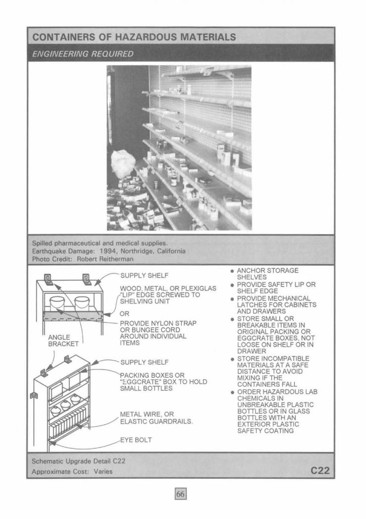
CONTAINERS OF HAZARDOUS MATERIALS
Spined pharmaceutical and medical supplies. Earthquake Damage: 1994. Nonhridge, Californta
Robert Reitherman
SUPPLY SHELF
WOOD, METAL, OR PLEXIGLAS "LIP" EDGE SCREWED TO SHELVING UNIT
OR ~-:"':-'"'-=--=-~""":"';;;i-_ PROVIDE NYLON STRAP
ANGLE BRACKET
OR BUNGEE CORD AROUND INDIVIDUAL ITEMS
Y -- SUPI'LY SHELF
-----~A~~II~N_~ BOXES OR "E.GGCRATE" BOX TO HOLD SMALL BOTTLES
METAL ~RE , OR ELASTIC GUARDRAILS.
BOLT
Schematic Upgrade Detail C22
Approximate Cost: Varies
• ANCHOR STORAGE SHELVES
• PROVIDE SAFETY LIP OR SHELF EDGE
• PROVIDE MECHANICAL LATCHES FOR CABINETS AND DRAWERS
• STORE SMALL OR BREAKABLE ITEMS IN ORIGINAL PACKING OR EGGCRATE BOXES, NOT LOOSE ON SHELF OR IN DRAWER
• STORE INCOMPATIBLE MATERIALS AT A SAFE DISTANCE TO AVOID MIXING IF THE CONTAINERS FALL
• ORDER HAZARDOUS LAB CHEMICALS IN UNBREAKABLE PLASTIC BOTTLES OR IN GLASS BOTTLES ~TH AN EXTERIOR PLASTIC SAFETY COATING
C22

GLASSWARE,-.......... GLASSWARE
BEE'S WAX OR DENTAL WAA. CAN RESTRAIN SMALL LIGHTWEIGHT OBJECTS. (REMOVE WITH CARE - WAX MAY
MONO-FILAMENT FISHING LINE ~ USED FOR GUY WlRES
LEAVE SMALL STAIN ON BASE OF OBJECT). ALTERNATlVE: USE PATCHES OF HOOK AND LOOP MATERIAL. [CAUTION - GLUE MAY AFFECT FINISH ON BASE OF OBJECT].
ANGLE BRACKET
BENT WJRE ARMS TO ENCIRCLE THE OBJECT. PROVIDE
" PADDlNG TO PROTECT ARTWORK.
DISPLAY CASE
PLACE OBJECT , fN CLOSE-FITIING GLASS OR PlEXI G LASS DISPLAY CASE. PEDESTAL MUST BE ANCHORED.
WOOD, PLA.STIC, OR PLEXIGLAS UP EDGE SCREWED TO SHELVING UNIT.
Upgr,ade Detail C26
1 Approximate Cost: Varies C26

FREESTANDING HALF-HEIGHT PARTITIONS
" Partitkm damage at Veterans Administration Medical Center in Sepulveda. Earthquake Damage: 1994, Northridge, California Photo Credit: Earthquake Research Institute. James O. Malley
I TO THE FLOOR; ATTACHED TO STABLE FURNITURE SUCH AS
; ANDIOR ARRANGED USING STABLE LAYOUTS.
PARTITIONS THAT SUPPORT HEAVY SHELVES ARE MORE LIKELY TO FALL.
___ BOLTTO
-_..J.J.~-P--- FLOOR OR TO STABLE FURNITURE
Upgrade Detail C27
Approximate Cost: $10 per hneal foot
A "ZIG-ZAG" LAYOUT IS MORE STABLE THAN A STRAIGHT LAYOUT WITH NO PERPENDICULAR WALLS
C27

MISCELLANEOUS FURNITURE
n
Earthquake Damage: 1994. Northridge. California Photo Credit: Eistner Inc.
_:-- ANGLE BRACKET
HUTCH, DISPLAY CASE, ETI:'I:~~~
KEEP TOP FREE OF HEAVY ITEMS ESPECIALLY IF LOCATED NEAR A PERSON SITTlNG AT DESK OR LYING IN BED.
EYEBOLT EMBEDDED IN WOOD STUD
FRAMED ITEM
WIRE ATTACHED TO FRAME INITH CLOSED HOOK OR CLOSED WIRE LOOP
OR ELASTIC GUARD, RAILS.
MICROWAVE, TV, OR STEREO EQUIPMENT, (SEE DETAIL C10 FOR COMPUTER EQUIPMENT)
PROVIDE ADDED RESTRAINT
(TWINE, NYLON, MONOFILAMENI~~~i~~~E3::::::::,., I ETC.) FOR POT THAT COULD •. ,,,,e ,\NuCAUSE INJURY
POTTED PLANT ---=~:::~~,::"-:-H()OK AND
LOOP MATERIAL
Upgrade Detail C28
Approximate Cost: Varies, approximately $50 per item C28
INSTALLATION NOTES For those details where the self-help approach is acceptable, a few words of caution are in order. Many items shown in the upgrade details can be purchased at any hardware store, but it is important to select hardware that is appropriate for the task at hand. A toggle bolt mounted in gypsum board may hold a light picture frame on the wall, but is not appropriate for any of the details shown in this guide. At the other extreme, a l-inch-diameter bolt is too large for a 2x4 wood stud, since the 11,4-inch-diameter hole you drill for the bolt will essentially eliminate the I1h-inch-wide stud. The following discussion provides general guidelines on hardware selection and installation procedures for the Do-It-Yourself details shown in this chapter.
Positive Connections The objective of non structural anchorage or restraint details is to provide what engineers refer to as a positive connection between the item and a hard attachment point, such as a solid wall, braced partition, concrete floor, or built-in countertop. Positive connections generally consist of some combination of screws, bolts, cables, chains, straps, steel angles, and other steel hardware. Positive connections do not rely on the frictional resistance produced by the effects of gravity. Neither the frictional resistance between the base of an object and the floor or other support nor such mechanical friction connections as C-clamps or thumbscrew clamps can be considered a positive connection.
The most common non structural connection details are.for wall attachments, floor or ceiling attachments, countertop attachments for smaller items, and attachments between adjacent items to create a more stable configuration.
Typical Wall Attachment Details Many types of non structural items can be anchored, braced, or tethered to an adjacent wall to
provide stability in an earthquake. Before installing any anchorage details, however, one should determine whether the wall has adequate structural capacity to support the non structural items. The wall element should consist of concrete, masonry, or structural framing members securely attached to the structural framing at both the top and bottom of the wall.
ANCHORAGE TO WOOD OR METAL STUD PARTITION WALLS Any type of attachment hardware or brace should be attached directly to a structural stud, not to the gypsum board or plaster wall covering. Gypsum board and most other interior wall coverings have little capacity to resist out-of-plane loading, that is, loads perpendicular to the wall. Most likely, a toggle bolt or nail will simply pull out during an earthquake, leaving a hole in the wall.
Typical wood and metal stud walls are constructed with vertical studs located at either 16 inches or 24 inches on centers. Many interior partition walls extend only to the ceiling line and should not be used to anchor heavy non structural items unless the top of the partition wall is braced to the structure above. Heavy items anchored to unbraced partitions may bring the partitions down with them if they fall during an earthquake. Partition bracing should consist of diagonal elements of similar size and material as the vertical studs, spaced every few feet, connecting the top of the partition to the structure above. Engineering advice may be needed if the partitions appear questionable.
The structural studs should be located at the start of a project to see that they are within reach of the items to be anchored. In situations where many items must be anchored to a stud wall, it is sometimes advantageous to install a mounting strip first in order to avoid having to relocate items to line them up with studs. Sometimes referred to as seismic molding, a

mounting strip is a horizontal member mounted to the walll and anchored to each stud. The strip should be located at or near the top of the items to be anchored!. Furniture or cabinets may then be anchored directly to the mounting strip without regard to the stud locations. A mounting strip may be constructed of a structural-grade wood 2x4 or 2x6 or a continuous steel channel or angle.
Recommended Hardware: • Attach steel angle directly to wood studs using a minimum ~-inch-diameter by 3-inch lag bolt. Embed the bolt at least 2 inches intOo the wood stud. • Attach steel angle to metal studs using #12 sheet-metal screws long enough to penetrate the flange material. Use twOo screws per connection, located 3 inches apart vertically. • Attachments to sheet-metal shelving or cabinets may be made by using a minimum t,4-mch-dia:.meter machine bolt. Where possible, attach the bolt through two layers of material, for ,example where the top and side or back and side pieces overlap. Otherwise, use an oversized 2-inch-diameter by 3/32-mch-thick fender washer with the nut on the inside of the cabinet to provide additional strength. • For seismic molding, use #14 flat-head wood screws with countersunk heads, with at least 2 inches embedded into the wood stud behind the wall covering. Locate screws along the centerline of the 2x4 or 2x6, and anchor the strip to each stud with maximum spacing of 24 inches on centers. For attachments to the molding strip', do not screw or bolt ,anything within 1 inch of each edge of a wood member. • Small quick-release safety hooks (carabiners) and nylon cord or straps are often available at sporting-goods stores that carry m0'untainclimbing equipment. These items may be useful for tethering small office equipment.
Not Recommended: • Toggle bolts mounted in gypsum board or plaster are not recommended for any of the
details presented here. • Nails have little capacity in tension or withdrawal, i. e., when you pull direct! y on the head of the nail. Thus, nails are not recommended fOor any 0'f these details either.
ANCHORAGE TO CONCRETE OR MASONRY WALLS Connections to existing concrete or grouted masonry walls should! be made with concrete anchor b olts. Many types of anchors are available from various vendors, including expansiOon anchors, sleeve anchors, and! epoxy anchors. Since the installation procedures and capacities for these anchors vary widely, it is important to check the 10'cal building code or vendor literature for the allowable load capacity and install the anchors in accordance with the manufacturer's r,ecommendatiOons. Holes into concrete or masonry walls should! be drilled with care to' avoid cutting any reinforcing steel (rebar). A magnetic device can be used! to locate the steel prior to drilling. If rebar is encountered while drilling, stop, ,and rel0'cate the hole; do not cut through the rebar.
The capacity of an anchor' bolt in concrete is governed by the strength of the concrete, the bolt diameter, the depth of embedment of the bolt into the concrete, the spacing between adjacent bolts, and the distance to the edge of the concrete. In order to develop the full capacity of a concrete anchor" the spacing should be at least 12 diameters, with a minimum edge distance Oof 6 diameters. The minimum embedment length is typically 8 bolt diameters. The bolt will have a greatly reduced capacity if it is too near an edge or too dose to an adjacent bolt or if it has insufficient embedment into the concrete.
The most common anchor bolts are wedge anchors, wher,e part of the shank expands to press against the sides of the hole as the nut is tightened. Other types of anchors include sleeve anchors and epoxy anchors. Sleev,e

anchors consist of a threaded sleeve installed directly into the concrete, flush with the concrete surface, and a bolt that is screwed into the sleeve. Sleeve anchors may be advantageous in situations where items may be moved frequently. The bolt may be removed, leaving the sleeve flush with the wall (or floor) and without leaving a protruding bolt. Epoxy anchors are inserted into slightly oversized holes with epoxy or polyester resin so that the adhesive will hold the bolt in place. Extreme care is required to ensure that the epoxy components are mixed in the proper proportions within the hole; otherwise the bolt will never reach the manufacturer's rated capacity. Quality control is critical for these bolts, and they are not recommended unless the installation is performed by experienced personnel.
Recommended Hardware and Procedures: • Do not cut reinforcing steel or electrical conduit in concrete or masonry walls. Locate the steel or conduit with a magnetic device prior to drilling. • Follow manufacturer's recommendations for installation. Remove dust from the hole prior to inserting the anchor bolt by using a hand-held vacuum cleaner; or blow the dust out with a bellows or a bulb. • For anchorage to reinforced concrete walls, expansion anchors are the most common and easiest to install. Typical sizes for wall anchorage of nonstructural items might be a 3/8-inch-diameter A307 bolt with 3-inch minimum embedment (allowable seismic loads 1450 pounds shear and 650 pounds tension) or a Ih-inch-diameter A307 bolt with 4-inch minimum embedment, 5-inch edge distance, and 6-inch spacing (allowable loads 2000 pounds shear and 1850 pounds tension) [12]. • To check the installation procedures and quality of workmanship, test a sample of installed bolts with a proof load. • Use galvanized or preferably stainless steel bolts and other hardware in locations where they will be exposed to moisture or weathering.
• Corrosion-resistant chains, eyebolts, and quick-release safety hooks can often be found at marine supply stores. These fasteners may be needed to provide wall anchorage for gas cylinders or other items stored outside or in a damp location. S For anchors in walls constructed of concrete masonry units, the expansion anchors should be installed only in grouted cells, i.e. locations where the cavity in the masonry unit is filled with grout and reinforcing steel. In order to achieve adequate embedment into the grout, longer bolts may have to be used in concrete masonry unit walls than in concrete walls. Unreinforced masonry walls, particularly cantilever partition walls, may not have adequate strength to anchor heavy non structural items. For light loads, up to 100 pounds or so, masonry toggle bolts can be used in ungrouted cells. • For unrein forced brick walls, engineering assistance is recommended. Published capacities for expansion anchors typically apply to concrete, not to brick. Anchorage to the floor may be a preferable solution in a brick building.
Not Recommended: • Adhesive or epoxy anchors are not recommended unless installed by experienced personnel. Proper quality control is critical for this type of anchor bolt. • Inserts made of lead or plastic placed in holes drilled in concrete or masonry and used with lag screws have very limited capacity and are not recommended.
Typical Floor and Ceiling Attachment Details For heavy items, anchorage to a concrete floor slab is often preferable to wall anchorage because it avoids the additional seismic load to the wall. Ceiling attachment details are required for many types of piping, ducts, light fixtures, and overhead fans or heaters. The type of detail used in each situation will depend on the structural materials
of the flom and ceiling framing.
ANCHORAGE TO WOOD FRAMING Because wood flooring typically does not have adequate strength to resist large concentrated forces, floor or ceiling anchorage hardware should be attached directly to the floor or ceiling beams or joists.
Recommended Hardware and Procedures: • Locate the floor or ceiling joists prior to beginning work. If wood beams or joists are not situated within a convenient distance, wood blocking may be used to provide additional anchor locations. Install blocking perpendicular to the joists, using, as a minimum, a member of the same size as the joists. Anchor the blocking with framing clips to the joists at each end. Do not toenail the blocking. • Wood scr,ews or lag bolts should be used for simple anchorage 'connections for lighter items. A lA-Inch-diameter by 3-inch lag bolt will be adequate for many types of connections. • For anchorage of heavier items to the roof or tloor,add blocking beneath the anchor location, run A307 bolts through the blocking, and tighten them on the underside with nuts and washers.
Not Recommended: • Do not anchor items directly to wood or plywood floor or roof sheathing, as these materials typically do not have adequate capacity to resist significant out-or-plane loads. • Nails are not r'ecommended for nonstructural anchorage details.
ANCHORAGE TO STEEL FRAMING Caution should be used in anchoring nonstructuraI items to structural steel framing. Engineering expertise may be needed to determine whether holes can be drilled through structural steel framing without compromising the integrity of the structural members.
There are several types of connection details
that do. not require holes through the steel framing.
Recommended Hardware: .' Vendor catalogues of hard!ware that ,can be used to provide both vertical and lateral support for piping often include fittings specifically designed for steel framing. While C-c1amps are not recommended, there are a variety of other devices that clamp mechanically around the flange of a steel beam or are designed to fit between column flanges. These devices are typically load-rated by the v,endors and come in :a variety of sizes. Besides bracing piping, this type of hardware might be used for bracing or anchoring items like lights or ceiling fans.
Al,,{CHORAGE TO CONCRETE FLOOR OR ROOF SLABS Concrete ,expansion anchors are the most common type of hardware used to anchor items. to. a concrete slab on grade or a structur.al!. floor slab. For heavy loads or concrete slabs less than 4-inches thick, it may be preferable to use through-bolts, i.e., machine bolts that go through the concrete slab and are fastened with nuts and steel plate washers on the underside of the slab.
Recommended Hardlwar,e and Procedures: • Refer to discussion of expansion anchors under concrete wall anchorage details. • Do not cut reinforcing steel in concrete slabs or beams. Locate the reinforcing steel and electrical conduit with a magnetic device prior to drilling holes in concrete slabs. .' For anchorage to a concrete foundation pad!, slab on gra.de" or suspended floor, check the drawings for the thickness of the concrete, or drill a small pilot hole frrst. While short expansion bolts may be adequate to pI'event sliding of low equipment, longer bolts with greater embedment are generally needed to prevent the combination of sliding and overturning forces for items that ar,e taller than they are wide.

• Typical hardware for floor anchorage of lighter non structural items might be with a l/z-inch-diameter A307 bolt with 4-inch minimum embedment and 6-inch spacing (allowable loads 1500 pounds shear and 1400 pounds tension). For heavy items, larger bolts are needed. For example, a l-inch-diameter A307 bolt with 7-inch minimum embedment and 12-inch spacing (allowable loads 3750 pounds shear and 2850 pounds tension) [12]. Engineering assistance is recommended for very heavy items. • If equipment is resting on leveling bolts or must be level for proper operation, vertically slotted connections may be needed to allow for adjustment.
Not Recommended: • A lA-inch-diameter expansion anchor has an allowable capacity for seismic loading of 650 pounds shear and 250 pounds tension [12]. (Note that the capacities cited above are for pure shear or pure tension. Combinations of shear and tension must be considered simultaneously, resulting in reduced capacity. For example, if you pull on the bolt with 200 pounds of tension, it will have the capacity to resist only approximately 300 pounds of shear.) These bolts are generally too small for most equipment or for fully loaded file cabinets, unless a number of bolts are used in combination.
Typical Shelf or Countertop Attachment Details If important or essential contents are to be secured, the shelf or mounting surface should be secured prior to anchoring non structural items. While standard desks and office tables are unlikely to overturn, they may slide during an earthquake. Desktop computers and printers can be anchored to the desk by means of hook-and-Ioop tape or various types of security devices designed to prevent theft.
Recommended Hardware and Procedures: • Unanchored desks or tables may slide and pull on the electrical cords of office equipment if the items are anchored to the tabletop. Electrical cords should have adequate slack to allow for movement of unanchored desks or tables. • Loose shelves should be secured to their wall or shelf brackets. Wood shelves that rest on wall-mounted brackets may be secured to the brackets with lh-inch-Iong wood screws. ., Many types of vendor-supplied anchorage and security devices are available for computer equipment. These may also be adapted for other types of countertop equipment, such as medical or laboratory equipment. Heavy-duty hook-and-Ioop tape with adhesive backing may be purchased at most hardware and fabric stores and can readily be cut into patches or strips. • Desktop computer equipment usually consists of several independent components. If items are stacked, make sure each component is anchored to the one beneath it and that the bottommost item is anchored to the desk. For tall configurations of items that do not have to be moved frequently, it may be more advantageous to tie an assembly of components together with nylon strap and then anchor the base to the desktop. • For light and nonessential items on shelves or countertops, a 1- to 2-inch lip secured to the edge of the counter or shelf may be adequate to prevent miscellaneous items from falling off. In this case, individual items need not be anchored.
Purchasing In some instances, it is easier to install non structural anchorage details for newly purchased equipment than for existing equipment. Many items are available off the shelf or can be special-ordered with seismic detailing. Some file cabinets come with predrilled holes for floor anchorage and strong latches on the drawers. Battery racks, industrial storage racks, and computer access floors can

be ordered that meet seismic requirements specified in the building code. It is always useful to inquire about the availability of seismic details when purchasing new equipment
Patching, Painting, and Corrosion Protection Most of the details shown here assume that the nonstructural item is situated in a dry" interior loOcation. In these 10catioOns. , some cosmetic patching and painting may be desirable, primarily for aesthetic reasoOns.
For basements" roofs., or other exterior locations., it is. important to provide adequate protection from weathering and ,corrosion. If attachment details perforate a roof membrane, appropriate sealants. or localized repair win be needed to avoid roof leakage. If expansion anchors. or other steel hardware will be exposed to moOist conditions or weathering, either stainless sreel or galvanized hardware should be selected to avoid corrosion and deterioration. Many types oOf paints and coatings are available that will help toO retard corrosion. Exterior earthquake protection devices may need periodic maintenance to avoid deterioration.
In cases. where a ,chain, latch, or tether is installed and users must remove and replace some hardware whenever they need to use the item, it may be helpful to select a bright or distinctive paint color as a reminder that the chain or hook needs to be refastened.
Safety Precautions As with any type oOf
construction work, there are safety pr,ecautlons that must be followed while installing nOilistructural attachment details. Employers and tradesmen must comply with numerous local, state, and federal safety regulations and follow guidelines. established for specific trades or industries. The following is not compr,ehensive but is a brief list oOf safety precautions that merit emphasis in connectioOn with the nonstructural attachment details shown here.
Recommended Procedures: • The people doing the installation work should have adequate training and supervision. Office workers or volunteers may not have the necessary background. • Electrical hazards are present around ,any· equipment supplied with electrical power.. It may be necessary to disconnect the power before starting work. Transformers are especially hazardous,. Transformers, switchgear,. and other electrical cabinets should be handled or opened onI y by qualified personnel. • The installation of most nonstructural restraint details involves the use of power tOOols. Personnel should use safety goggles and other protection recommended by tool manufacturers, and all workplace safety standards should be followed. • Many heavy pieces of furniture or ·equipment may have to be moved temporarily in order to install seismic restraint details. Unless proper lifting techniques are utilized, back injuries or other injuries may result [19].