non conventional energy sources...
TRANSCRIPT
INTERMEDIATE VOCATIONAL COURSE Second Year
NON CONVENTIONAL ENERGY
SOURCES LAB For the Course of Rural Engineering Technician
State Institute of Vocational Education Directorate of Intermediate Education Govt. of Andhra Pradesh, Hyderabad.
2005
AUTHOR
Sri Shali Habibulla
M.Tech (Ref & A/c), Hons. C.H.E. M.I.S.T.E. Department of Rural Engineering Technician
Govt. Junior College (Boys) New, Town, Anantapur
PREFACE
The main objective of vocational education is to train the students at +2 level
for meeting the demands for the skilled manpower in both organised and unorganised
sectors and also to provide an alternative channel for those who aimlessly persue
higher education and to prepare them for self reliance. The State Institute of
Vocational Education (SIVE) in collaboration with the Board of Intermediate
Education, Andhra Pradesh has developed curriculum for 43 vocational courses in the
field of
Engineering & Technology
Agriculture
Health & Paramedical
Business & Commerce
Home Science and Humanities
Accordingly the text books have been developed by SIVE as per the
restructured curriculum by utilizing the services of various professional teachers in
the respective fields. I am sure that this book will be immensely useful to the
vocational students and teachers in understanding the concepts.
I wish to place my sincere thanks on record to Sri Shali Habibulla, Author of
this text book for extending his support in developing this book for printing and
publishing.
I shall be grateful to receive suggestions and observations from all the readers
which would help in bringing out a revised and improved version of this book in
future.
Sri. Shashank Goel, I.A.S., Director & Secretary Board of Intermediate Education Andhra Pradesh, Hyderabad
CONTENTS
Page No. 1. Solar Radiation Measurement
2. Solar Distillation
3. Solar Pumping
4. Solar Cooker
5. Preparation of delicious food by using solar cooker.
6. Solar Water Heater (Thermosiphon)
7. Solar Water Heater (Forced Circulation)
8. Solar Lanterns and Street light
9. Study of KVIC Bio gas plant
10. Study of Janata Bio gas plant
11. Study of Deenabandhu Biogas plant
12. Study of fuel cells.
Non Conventional Energy Sources Lab
1
SOLAR RADIATION MEASUREMENT
Experiment No : 1.1
Aim : Study of Solar Radiation by using Pyranometer.
Apparatus : 1. Black surface
2. Glass domes
3. Guard plate
4. Three levelling screws
5. Mounting plate
6. Grouted boLts
7. Platform
8. Thermopile
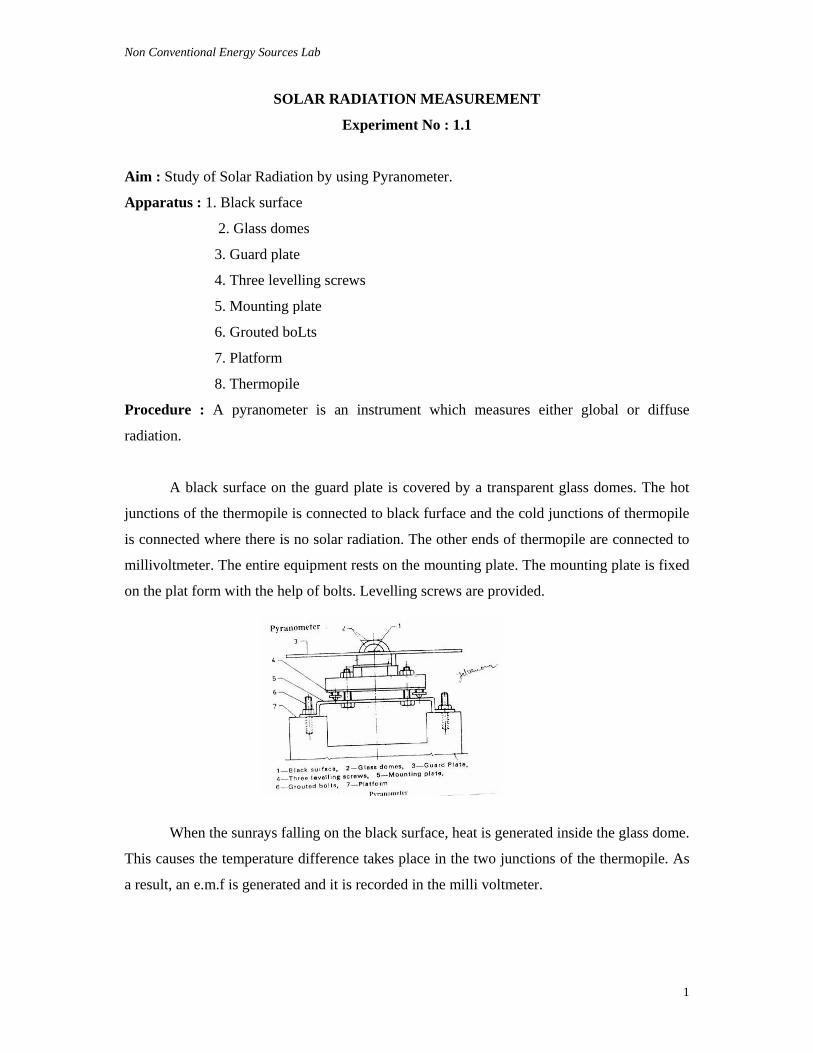
Procedure : A pyranometer is an instrument which measures either global or diffuse
radiation.
A black surface on the guard plate is covered by a transparent glass domes. The hot
junctions of the thermopile is connected to black furface and the cold junctions of thermopile
is connected where there is no solar radiation. The other ends of thermopile are connected to
millivoltmeter. The entire equipment rests on the mounting plate. The mounting plate is fixed
on the plat form with the help of bolts. Levelling screws are provided.
When the sunrays falling on the black surface, heat is generated inside the glass dome.
This causes the temperature difference takes place in the two junctions of the thermopile. As
a result, an e.m.f is generated and it is recorded in the milli voltmeter.
Non Conventional Energy Sources Lab
2
Data Required to be noted
Name of the instrument : __________________________________________
Name of the manufacturer / supplier : __________________________________________
Sl. No.
Experiment Conducting Time Duration hrs. e.m.f. Produced
Quesitons For Evaluation :
After performing the practical task the students are required to answer the
following questions.
Q1. What is Pyranometer?
Ans. A Pyranometer is an instrument which measures either global or diffuse radiation.
Q2. What are the main parts of Pyranometer?
Ans. 1. Black surface; 2. Glass domer, 3. Guard plate; 4. Three levelling screws; 5. Mounting
plate; 6. Grouted bolts; 7. Platform; 8. Thermopile.
Q3. How many junctions has thermopile and what are they?
Ans. Thermophile has two junctions. They are : (a) Cold junction and (b) Hot junction.
Q4. What is the use of millivoltmeter?
Ans. It records an e.m.f. (electro motive force) generated.
Non Conventional Energy Sources Lab
3
SOLAR DISTILLATION
EXPERIMENT NO : 2.1
Aim : Study of Solar Distillation or Solar Still.
Apparatus : 1. Transparent Covers
2. Filler
3. Over flow line
4. Insulation
5. Blackened surface
6. Basin
Objective :
Fresh water is a necessity for the sustenance of life and also the key to man’s
prosperity. It is observed that, arid and costal areas which are thinly populated, the family
members are always busy in bringing fresh water from a long distance. In these areas solar
energy is plentiful and can be used for converting saline water in to distilled water by using
solar still.
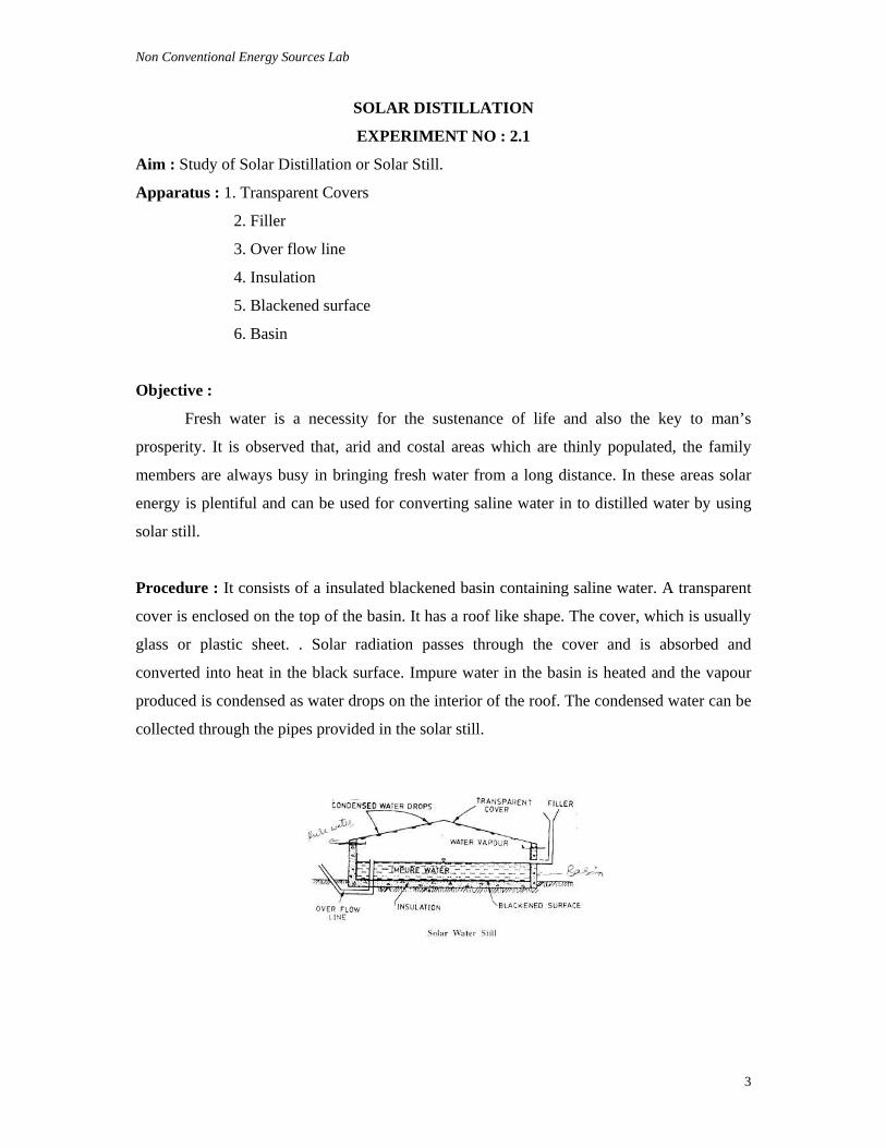
Procedure : It consists of a insulated blackened basin containing saline water. A transparent
cover is enclosed on the top of the basin. It has a roof like shape. The cover, which is usually
glass or plastic sheet. . Solar radiation passes through the cover and is absorbed and
converted into heat in the black surface. Impure water in the basin is heated and the vapour
produced is condensed as water drops on the interior of the roof. The condensed water can be
collected through the pipes provided in the solar still.
Non Conventional Energy Sources Lab
4
Data Required to be noted
Name of the instrument : __________________________________________
Name of the manufacturer / supplier : __________________________________________
Sl. No. Experiment Conducting
Time
Duration hrs.
Quantity of Saline of
Impure Water
Quantity of Pure Water
Collected
Remarks
Questions for evaluation :
After performing the practical task the students are required to answer the
following questions :
Q1. What are the main parts of Solar Distillation or Solar Still ?
Ans. 1. Transparent covers; 2. Filler; 3. Over flow line; 4. Insulation;
5. Blackened surface; 6. Basin.
Q2. What is the use of Transparent ?
Ans. Transparent cover acts as an solar collector.
Q3. What acts as an absorber ?
Ans. A black body acts as an absorber.
Q4. What is the use of Solar Distillation ?
Ans. The impure water can be purified with the help of Solar Distillation.
Non Conventional Energy Sources Lab
5
SOLAR PUMPING
EXPERIMENT NO : 3.1
Aim : Study of solar water pumping
Apparatus : 1. Solar collector array
2. Heat exchanger
3. Organic fluid
4. Heat engine
5. Condenser
6. Pump
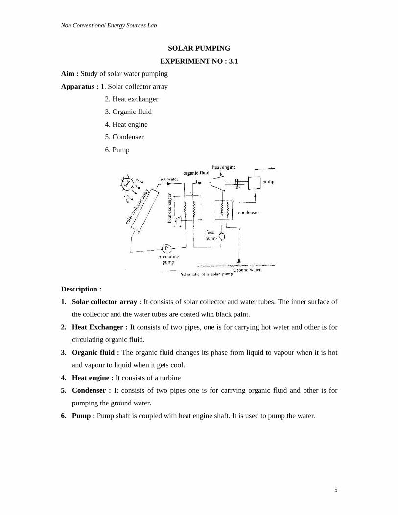
Description :
1. Solar collector array : It consists of solar collector and water tubes. The inner surface of
the collector and the water tubes are coated with black paint.
2. Heat Exchanger : It consists of two pipes, one is for carrying hot water and other is for
circulating organic fluid.
3. Organic fluid : The organic fluid changes its phase from liquid to vapour when it is hot
and vapour to liquid when it gets cool.
4. Heat engine : It consists of a turbine
5. Condenser : It consists of two pipes one is for carrying organic fluid and other is for
pumping the ground water.
6. Pump : Pump shaft is coupled with heat engine shaft. It is used to pump the water.
Non Conventional Energy Sources Lab
6
Working :
When the sun rays falls on the solar collector, black body absorbs the sun rays and
water in the tubes gets heated up and circulates in the heat exchanger. Through the heat
exchanger, hot water is again pumped back in the solar collector with the help of a pump.
The organic fluid in the other tube sences the heat produced in the heat exchanger and
converts its phase in to vapour. The vapour runs the turbine provided in the heat engine and
losses its heat, and again converted in to liquid. This organic fluid again pumped back in to
the heat exchanger with the help of a feed pump.
Ground water is pumped with the help of a pump, which is coupled with heat engine.
Non Conventional Energy Sources Lab
7
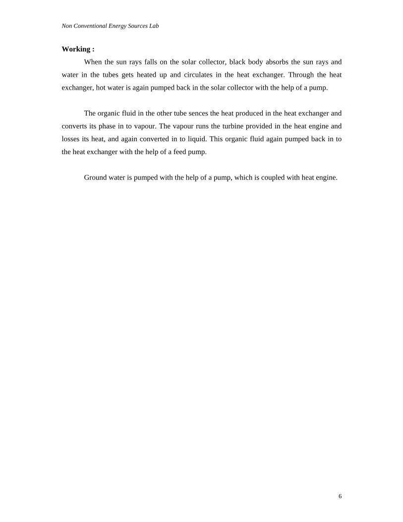
Data Required to be noted
Name of the instrument : __________________________________________
Sl. No. Experiment Conducting Time
Duration hrs
Amount of Water Collected
Remarks
Questions for Evaluation :
After performing the practical task the students are required to answer the
following questions:
Q1. What are the main parts of Solar Water Pumping ?
Ans. 1. Solar collector array; 2. Heat exchanger; 3. Organic fluid; 4. Heat engine;
5.Condenser; 6. Pump
Q2. Describe solar collector array ?
Ans. It consists of solar collector and water tubes. The inner surface of the collector and the
water tubes are coated with black paint.
Q3. Describe Heat Exchanger ?
Ans. It consists of two pipes, one is for carrying hot water and other is for circulating organic
fluid.
Q4. Describe organic fluid ?
Ans. The organic fluid changes its phase from liquid to vapour when it is hot and vapour to
liquid when it gets cool.
Q5. Describe Heat engine ?
Ans. It consists of a turbine and it is coupled with a pump.
Q6. Describe condenser ?
Ans. It consists of two pipes one is for carrying organic fluid and other is for pumping the
ground water.
Q7. Describe Pump ?
Ans. Pump is used to pump the water and it is coupled with heat engine.
Non Conventional Energy Sources Lab
8
SOLAR COOKER
EXPERIMENT NO : 4.1
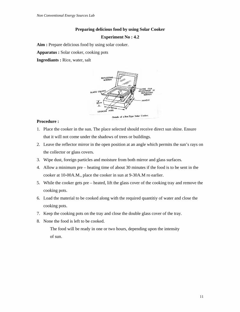
Aim : To study the constructional details of a box type solar cooker.
Apparatus : 1. Insulated box
2. Two transparent glass plates (collectors) 3. Reflecting mirror 4. Guide for adjustment of reflecting mirror 5. Handle 6. Cooking pots 7. Black board paint (Absorber)
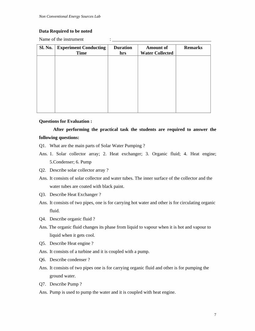
Procedure :
Two transparent glass plates of 3mm thick are fixed on the top of the insulated box,
keeping obout 25mm distance between the two glass covers. Neopreme rubber sealing is
provided around the glass covers and the cooker box. A black paint is coated on the surface
of the vessels and inside the box. This black body acts as an absorber.
The solar radiation entering the box are of short wave length. The two glass covers
minimises the heat loss and transmission of long wave radiation.
When the sun rays falls on collectors or glass plates, enters in to the cooker box. The
black body absorbs the solar radiation and generates heat inside the box. The cooking pots
gets heat energy and food will be cooked.
Solar energy can be tracked by using reflector or mirror. A mechanism or clamp is
provided to adjust the reflector at different angles on the cooker box.
Insulating materials like glass wool or saw dust is filled in the space between
blackened tray and outer cover of the box. This minimises heat losses.
Non Conventional Energy Sources Lab
9
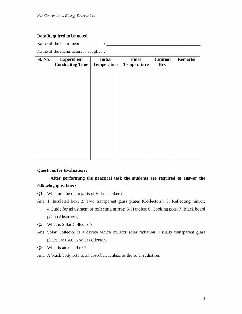
Data Required to be noted
Name of the instrument : __________________________________________
Name of the manufacturer / supplier : ________________________________________
Sl. No. Experiment Conducting Time
Initial Temperature
Final Temperature
Duration Hrs
Remarks
Questions for Evaluation :
After performing the practical task the students are required to answer the
following questions :
Q1. What are the main parts of Solar Cooker ?
Ans. 1. Insulated box; 2. Two transparent glass plates (Collectors); 3. Reflecting mirror;
4.Guide for adjustment of reflecting mirror; 5. Handles; 6. Cooking pots; 7. Black board
paint (Absorber);
Q2. What is Solar Collector ?
Ans. Solar Collector is a device which collects solar radiation. Usually transparent glass
plates are used as solar collectors.
Q3. What is an absorber ?
Ans. A black body acts as an absorber. It absorbs the solar radiation.
Non Conventional Energy Sources Lab
10
Q4. What is the use of reflector ?
Ans. It is used for tracking the solar energy. Usually a mirror is used as a reflector. A
mechanism or clamp is provided to adjust the reflector at different angles on the cooker
box.
Q5. What is the use of insulating material ?
Ans. The material which does not conduct heat is called insulating material. Insulating
materials like glass wool or saw dust is filled in the space between blackened tray and
outer cover of the box. This minimises heat losses.
Q6. What is the thickness of transparent glass plates ?
Ans. The thickness of transparent glass plate is 3mm.
Q7. What is the distance between the two glass covers ?
Ans. The distance between the two glass covers is 25mm.
Non Conventional Energy Sources Lab
11
Preparing delicious food by using Solar Cooker
Experiment No : 4.2
Aim : Prepare delicious food by using solar cooker.
Apparatus : Solar cooker, cooking pots
Ingrediants : Rice, water, salt
Procedure :
1. Place the cooker in the sun. The place selected should receive direct sun shine. Ensure
that it will not come under the shadows of trees or buildings.
2. Leave the reflector mirror in the open position at an angle which permits the sun’s rays on
the collector or glass covers.
3. Wipe dust, foreign particles and moisture from both mirror and glass surfaces.
4. Allow a minimum pre – heating time of about 30 minutes if the food is to be sent in the
cooker at 10-00A.M., place the cooker in sun at 9-30A.M ro earlier.
5. While the cooker gets pre – heated, lift the glass cover of the cooking tray and remove the
cooking pots.
6. Load the material to be cooked along with the required quantitiy of water and close the
cooking pots.
7. Keep the cooking pots on the tray and close the double glass cover of the tray.
8. None the food is left to be cooked.
The food will be ready in one or two hours, depending upon the intensity
of sun.
Non Conventional Energy Sources Lab
12
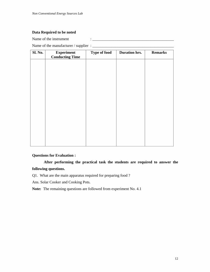
Data Required to be noted
Name of the instrument : __________________________________________
Name of the manufacturer / supplier : __________________________________________
Sl. No. Experiment Conducting Time
Type of food Duration hrs. Remarks
Questions for Evaluation :
After performing the practical task the students are required to answer the
following questions.
Q1. What are the main apparatus required for preparing food ?
Ans. Solar Cooker and Cooking Pots.
Note: The remaining questions are followed from experiment No. 4.1
Non Conventional Energy Sources Lab
13
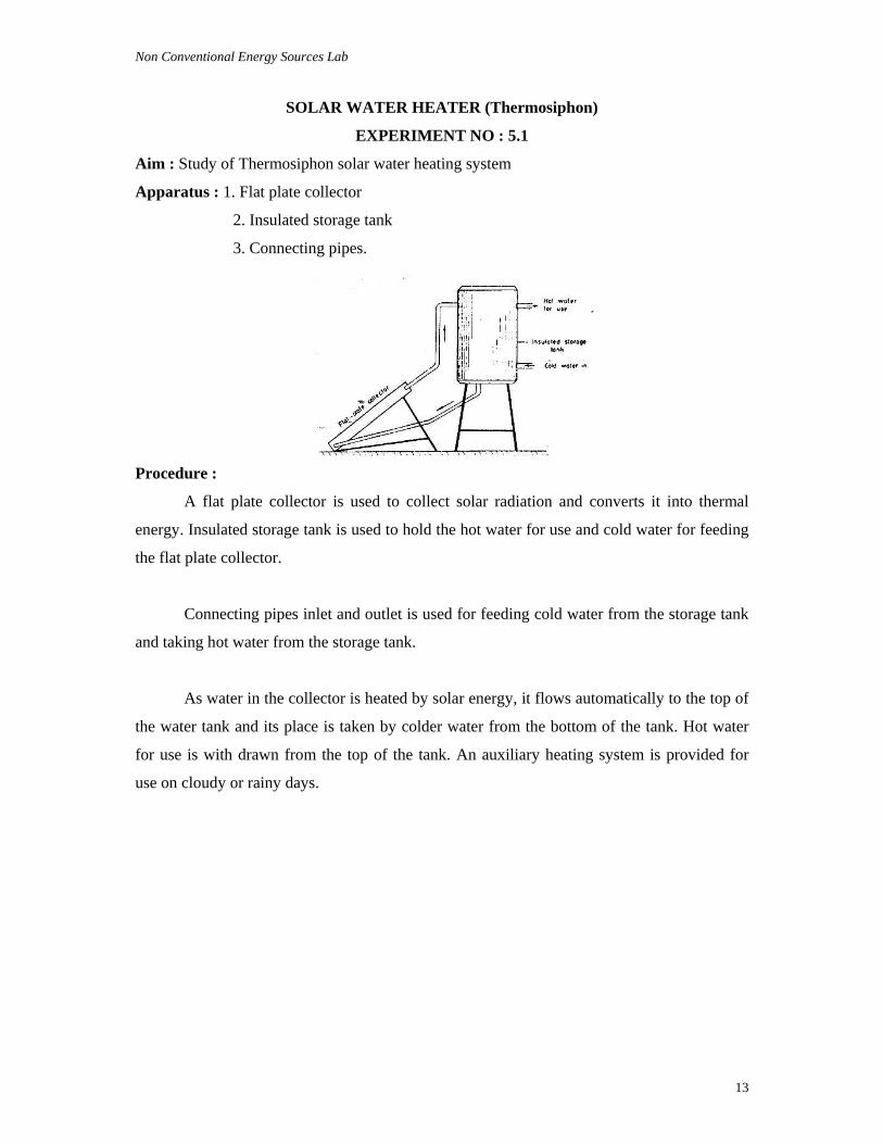
SOLAR WATER HEATER (Thermosiphon)
EXPERIMENT NO : 5.1
Aim : Study of Thermosiphon solar water heating system
Apparatus : 1. Flat plate collector
2. Insulated storage tank
3. Connecting pipes.
Procedure :
A flat plate collector is used to collect solar radiation and converts it into thermal
energy. Insulated storage tank is used to hold the hot water for use and cold water for feeding
the flat plate collector.
Connecting pipes inlet and outlet is used for feeding cold water from the storage tank
and taking hot water from the storage tank.
As water in the collector is heated by solar energy, it flows automatically to the top of
the water tank and its place is taken by colder water from the bottom of the tank. Hot water
for use is with drawn from the top of the tank. An auxiliary heating system is provided for
use on cloudy or rainy days.
Non Conventional Energy Sources Lab
14
Data Required to be noted
Name of the instrument : __________________________________________
Name of the manufacturer / supplier : __________________________________________
Sl. No.
Experiment conducting Time
Quantity of Water
Initial Temperature
Final Temperature
Duration hrs.
Questions for Evaluation :
After performing the practical task the students are required to answer the
following questions :
Q1. What are the apparatus required for solar water heating system ?
Ans. 1. Flat plate collector; 2. Insulated storage tank; 3. Connecting pipes
Q2. What is the use of flat plate collector ?
Ans. A flat plate collector is used to collect solar radiation and converts it in to thermal
energy.
Q3. What are the different types of solar water heating systems ?
Ans. 1. Thermosiphon or Natural Circulation System and 2. Forced circulation system.
Q4. What is the use of an auxiliary heating system ?
Ans. An auxiliary heating system is provided for use on cloudy or rainy days.
Q5. What is the use of insulating material ?
Ans. It minimises heat losses.
Non Conventional Energy Sources Lab
15
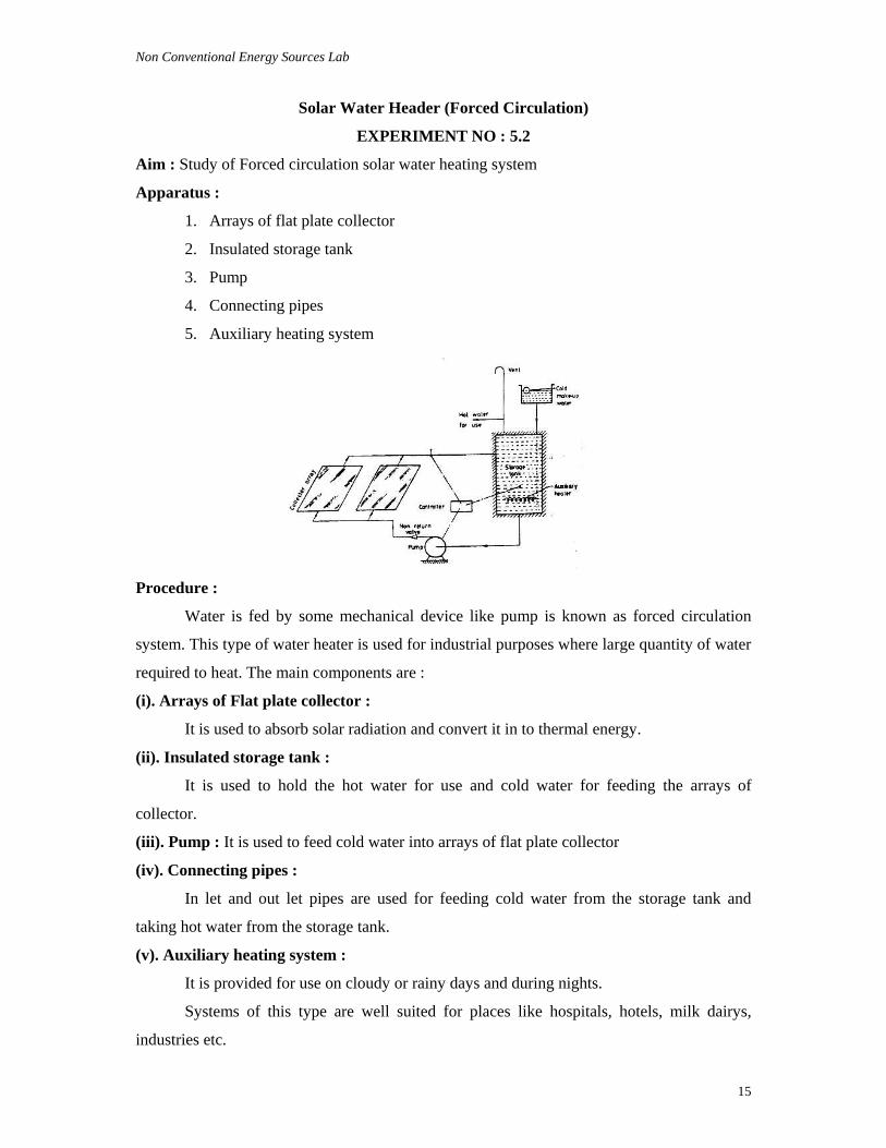
Solar Water Header (Forced Circulation)
EXPERIMENT NO : 5.2
Aim : Study of Forced circulation solar water heating system
Apparatus :
1. Arrays of flat plate collector
2. Insulated storage tank
3. Pump
4. Connecting pipes
5. Auxiliary heating system
Procedure :
Water is fed by some mechanical device like pump is known as forced circulation
system. This type of water heater is used for industrial purposes where large quantity of water
required to heat. The main components are :
(i). Arrays of Flat plate collector :
It is used to absorb solar radiation and convert it in to thermal energy.
(ii). Insulated storage tank :
It is used to hold the hot water for use and cold water for feeding the arrays of
collector.
(iii). Pump : It is used to feed cold water into arrays of flat plate collector
(iv). Connecting pipes :
In let and out let pipes are used for feeding cold water from the storage tank and
taking hot water from the storage tank.
(v). Auxiliary heating system :
It is provided for use on cloudy or rainy days and during nights.
Systems of this type are well suited for places like hospitals, hotels, milk dairys,
industries etc.
Non Conventional Energy Sources Lab
16
Data Required to be noted
Name of the instrument : __________________________________________
Name of the manufacturer / supplier : __________________________________________
Sl. No.
Experiment Conducting
Time
Quantity of Water
Initial Temperature
Final Temperature
Duration hrs.
Remarks
Questions for Evaluation :
After performing the practical task the students are required to answer the
following questions :
Q1. What are the main apparatus used in forced circulation solar water heating system ?
Ans. 1. Arrays of flat plate collector; 2. Insulated storage tank; 3. Pump; 4. Connecting pipes;
5. Auxiliary heating system;
Note : The remaining questions are similar to experiment No. 5.1
Non Conventional Energy Sources Lab
17
SOLAR LANTERNS AND STREET LIGHT
EXPERIMENT NO : 6.1
Aim : Study of Solar Street Lighting and Lanterns.
Apparatus : 1. Photovoltaic module or solar array
2. Lighting device
3. Inverter
4. Battery
Objectives of solar lighting :
In our country out of six lack villages, one lack village are still to be electrified. Even
in electrified villages, only a quarter of house – holds have proper connection.
The bulk of rural house – holds in India, normally use kerosene lanterns for meeting
their lighting requirements. These lanterns provided insufficient and poor quality of light.
A variety of solar photo – voltaic system have been developed and employed for rural
applications such as lighting.
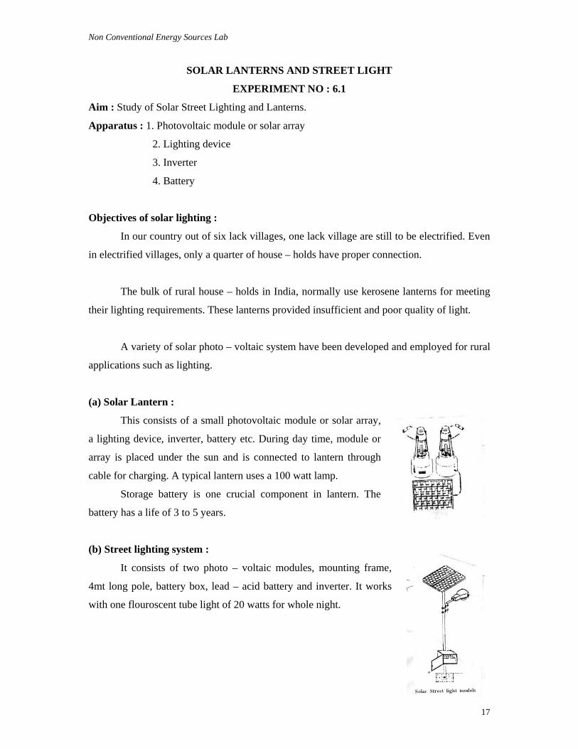
(a) Solar Lantern :
This consists of a small photovoltaic module or solar array,
a lighting device, inverter, battery etc. During day time, module or
array is placed under the sun and is connected to lantern through
cable for charging. A typical lantern uses a 100 watt lamp.
Storage battery is one crucial component in lantern. The
battery has a life of 3 to 5 years.
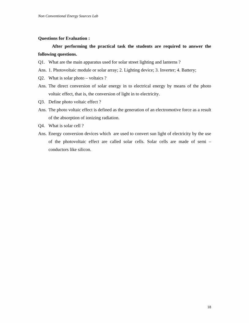
(b) Street lighting system :
It consists of two photo – voltaic modules, mounting frame,
4mt long pole, battery box, lead – acid battery and inverter. It works
with one flouroscent tube light of 20 watts for whole night.
Non Conventional Energy Sources Lab
18
Questions for Evaluation :
After performing the practical task the students are required to answer the
following questions.
Q1. What are the main apparatus used for solar street lighting and lanterns ?
Ans. 1. Photovoltaic module or solar array; 2. Lighting device; 3. Inverter; 4. Battery;
Q2. What is solar photo – voltaics ?
Ans. The direct conversion of solar energy in to electrical energy by means of the photo
voltaic effect, that is, the conversion of light in to electricity.
Q3. Define photo voltaic effect ?
Ans. The photo voltaic effect is defined as the generation of an electromotive force as a result
of the absorption of ionizing radiation.
Q4. What is solar cell ?
Ans. Energy conversion devices which are used to convert sun light of electricity by the use
of the photovoltaic effect are called solar cells. Solar cells are made of semi –
conductors like silicon.
Non Conventional Energy Sources Lab
19
BIO GAS
Experiment No : 7.1
Aim : Study of K.V.I.C Bio gas plant.
Apparatus :
1. Digester
2. Gas holder.
3. Gas pipe
4. Mixing pit
5. Out let
6. Inlet pipe
7. Outlet pipe
8. Partition wall
9. Cow dung or organic matter
10. Water
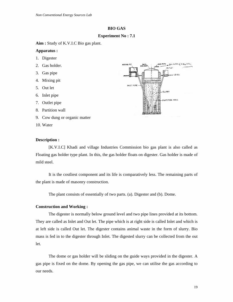
Description :
[K.V.I.C] Khadi and village Industries Commission bio gas plant is also called as
Floating gas holder type plant. In this, the gas holder floats on digester. Gas holder is made of
mild steel.
It is the costliest component and its life is comparatively less. The remaining parts of
the plant is made of masonry construction.
The plant consists of essentially of two parts. (a). Digester and (b). Dome.
Construction and Working :
The digester is normally below ground level and two pipe lines provided at its bottom.
They are called as Inlet and Out let. The pipe which is at right side is called Inlet and which is
at left side is called Out let. The digester contains animal waste in the form of slurry. Bio
mass is fed in to the digester through Inlet. The digested slurry can be collected from the out
let.
The dome or gas holder will be sliding on the guide ways provided in the digester. A
gas pipe is fixed on the dome. By opening the gas pipe, we can utilise the gas according to
our needs.
Non Conventional Energy Sources Lab
20
Bio gas production ;
Bio gas produces in two phases
1. Acid Phase and 2. Methane Phase.
When the organic matters is decomposed or formented in the absence of air anaerobic
group organisms called acid formers produces. This is called as Acid Phase.
The acid former bacterias are then converted into Methane (CH4) and carbon-di-oxide
(CO2) after two weeks. The bacterias which are strictly anaerobs are called Methane former
bacterias. The combination of Methane and carbon-di-oxide is known as Bio gas.
The produced bio gas will be stored in the dome. At the bottom of the digester a
partition wall is constructed. This wall devides or separates In let and Out let. The digested
slurry will be removed from the out let. The digested sludge contains nitrogen, phosphorous
and potassium. It can be used as an excellent fertilizer.
The calorific value of Bio gas is 1600 to 2500 KJ/m3. It is an excellent fuel for
cooking, lighting and for running the engines.
Data Required to be noted
Name of the Bio gas plant : __________________________________________
Location : __________________________________________
Sl. No.
Date of feeding Bio mass
Quantity of cow dung
Quantity of water mixed
Date of Bio gas production
Quantity of Bio gas produced
Non Conventional Energy Sources Lab
21
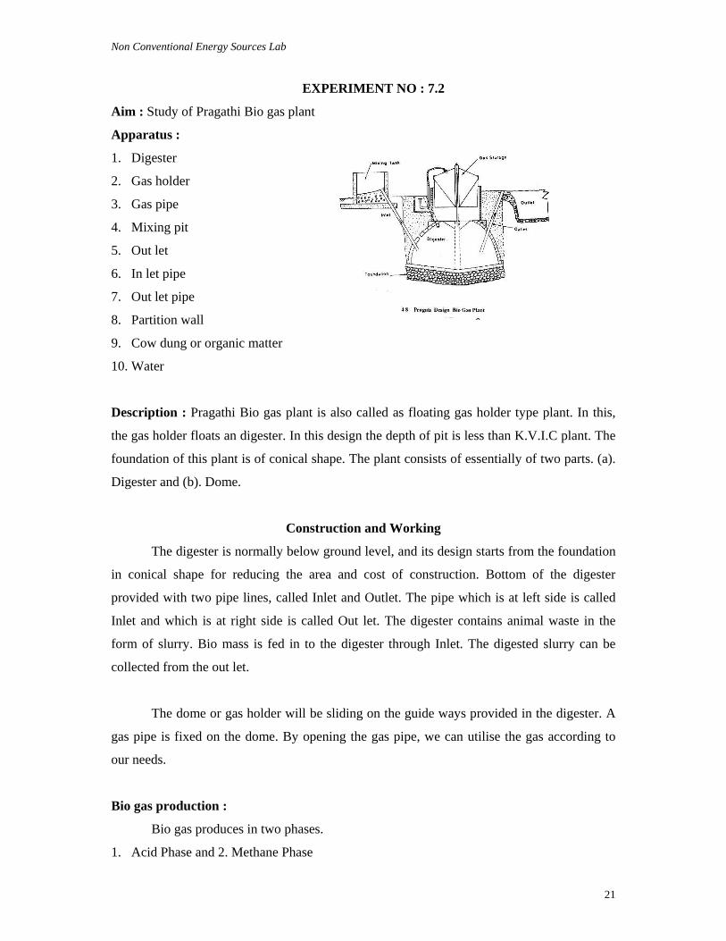
EXPERIMENT NO : 7.2
Aim : Study of Pragathi Bio gas plant
Apparatus :
1. Digester
2. Gas holder
3. Gas pipe
4. Mixing pit
5. Out let
6. In let pipe
7. Out let pipe
8. Partition wall
9. Cow dung or organic matter
10. Water
Description : Pragathi Bio gas plant is also called as floating gas holder type plant. In this,
the gas holder floats an digester. In this design the depth of pit is less than K.V.I.C plant. The
foundation of this plant is of conical shape. The plant consists of essentially of two parts. (a).
Digester and (b). Dome.
Construction and Working
The digester is normally below ground level, and its design starts from the foundation
in conical shape for reducing the area and cost of construction. Bottom of the digester
provided with two pipe lines, called Inlet and Outlet. The pipe which is at left side is called
Inlet and which is at right side is called Out let. The digester contains animal waste in the
form of slurry. Bio mass is fed in to the digester through Inlet. The digested slurry can be
collected from the out let.
The dome or gas holder will be sliding on the guide ways provided in the digester. A
gas pipe is fixed on the dome. By opening the gas pipe, we can utilise the gas according to
our needs.
Bio gas production :
Bio gas produces in two phases.
1. Acid Phase and 2. Methane Phase
Non Conventional Energy Sources Lab
22
When the organic matter is decomposed or formented in the absence of air, anaerobic
group organisms called acid formers produces. This is called as Acid Phase.
The acid former bacterias are then converted in to Methane (CH4) and carbon-di-oxide
(CO2) after two weeks. The bacterias which are strictly anaerobs are called Methane former
bacterias. The combination of Methane and Carbon-di-oxide is known as Bio gas.
The produced bio gas will be stored in the dome. At the bottom of the digester a partition
wall is constructed. This wall devides or separates Inlet and Outlet. The digested slurry will
be removed from the out let. The digested sludge contains nitrogen, phosphorous and
potassium. It can be used as an excellent fertilizer.
The calorific value of Bio gas is 1600 to 2500 KJ/m3. It is an excellent fuel for cooking,
lighting, and for running the engines.
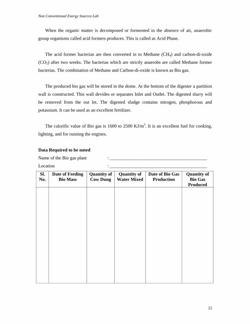
Data Required to be noted
Name of the Bio gas plant : __________________________________________
Location : __________________________________________
Sl. No.
Date of Feeding Bio Mass
Quantity of Cow Dung
Quantity of Water Mixed
Date of Bio Gas Production
Quantity of Bio Gas
Produced
Non Conventional Energy Sources Lab
23
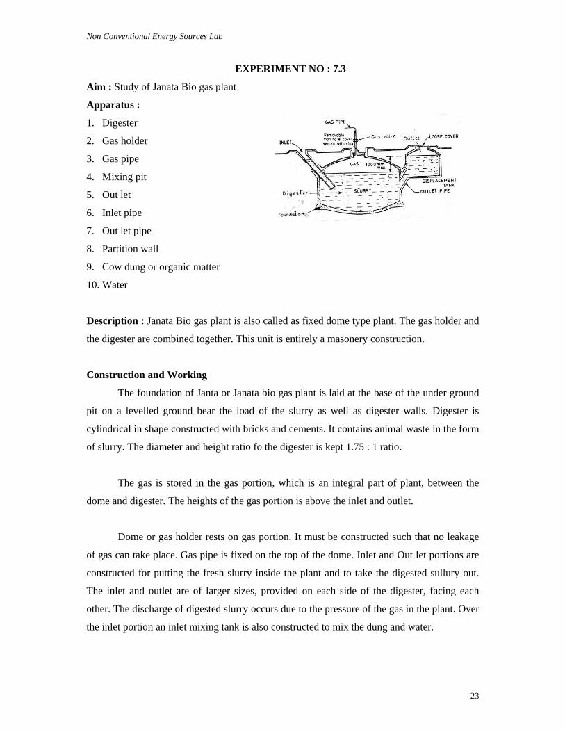
EXPERIMENT NO : 7.3
Aim : Study of Janata Bio gas plant
Apparatus :
1. Digester
2. Gas holder
3. Gas pipe
4. Mixing pit
5. Out let
6. Inlet pipe
7. Out let pipe
8. Partition wall
9. Cow dung or organic matter
10. Water
Description : Janata Bio gas plant is also called as fixed dome type plant. The gas holder and
the digester are combined together. This unit is entirely a masonery construction.
Construction and Working
The foundation of Janta or Janata bio gas plant is laid at the base of the under ground
pit on a levelled ground bear the load of the slurry as well as digester walls. Digester is
cylindrical in shape constructed with bricks and cements. It contains animal waste in the form
of slurry. The diameter and height ratio fo the digester is kept 1.75 : 1 ratio.
The gas is stored in the gas portion, which is an integral part of plant, between the
dome and digester. The heights of the gas portion is above the inlet and outlet.
Dome or gas holder rests on gas portion. It must be constructed such that no leakage
of gas can take place. Gas pipe is fixed on the top of the dome. Inlet and Out let portions are
constructed for putting the fresh slurry inside the plant and to take the digested sullury out.
The inlet and outlet are of larger sizes, provided on each side of the digester, facing each
other. The discharge of digested slurry occurs due to the pressure of the gas in the plant. Over
the inlet portion an inlet mixing tank is also constructed to mix the dung and water.
Non Conventional Energy Sources Lab
24
Bio gas Production
Bio gas produces in two phases.
1. Acid Phase and 2. Methane Phase
When the organic matter is decomposed or formented in the absence of air anaerobic
group organisms called acid formers produces. This is called as Acid Phase.
The Acid former bacterias are then converted in to Methane (CH4) and Carbon-di-oxide
(CO2) after two weeks. The bacterias which are strictly anaerobs are called Methane former
bacterias. The combination of Methane and Carbon-di-oxide is known as Bio gas.
The produced Bio gas stored in the gas holder can be utilised by opening the gas pipe
according to our needs.
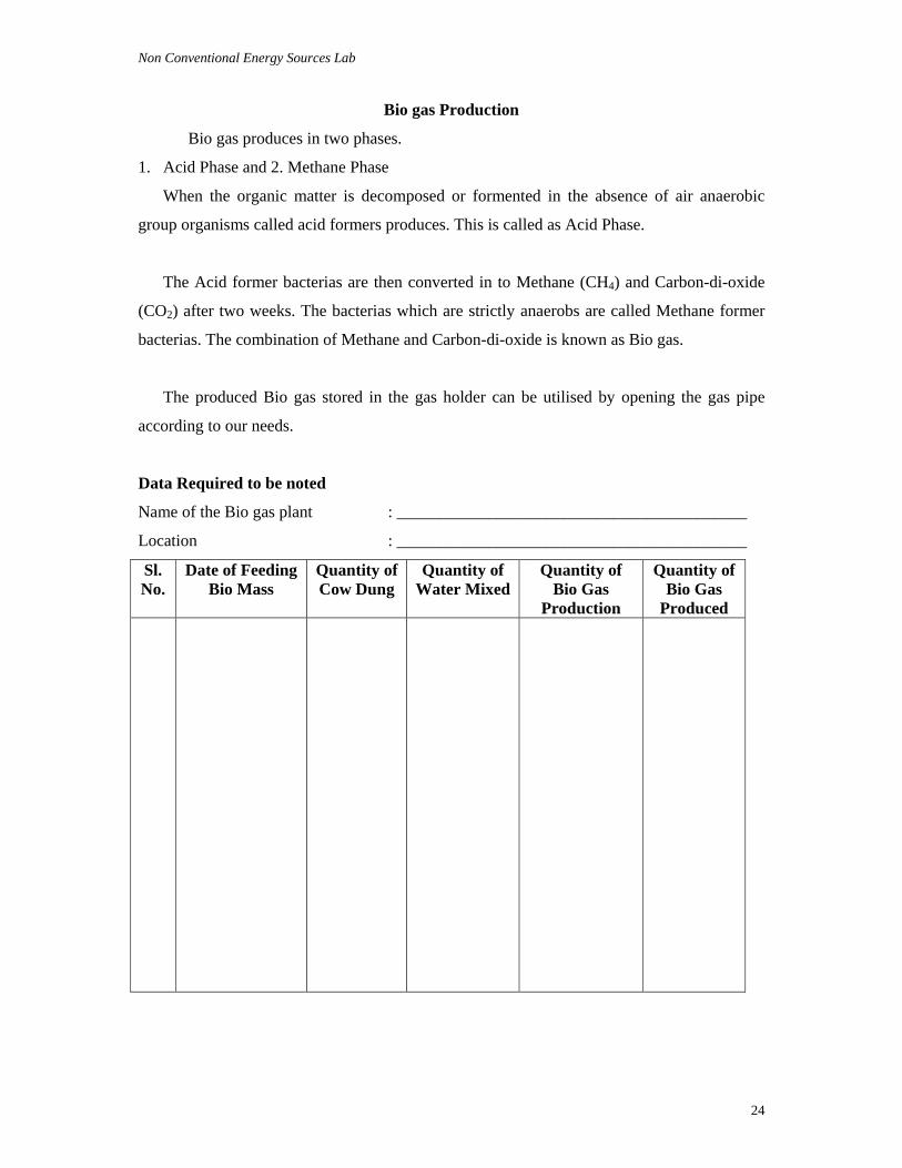
Data Required to be noted
Name of the Bio gas plant : __________________________________________
Location : __________________________________________
Sl. No.
Date of Feeding Bio Mass
Quantity of Cow Dung
Quantity of Water Mixed
Quantity of Bio Gas
Production
Quantity of Bio Gas
Produced
Non Conventional Energy Sources Lab
25
EXPERIMENT NO : 7.4
Aim : Study of Deenabandhu Bio gas plant
Apparatus :
1. Digester
2. Gas holder
3. Gas pipe
4. Mixing pit
5. Out let
6. In let pipe
7. Out let pipe
8. Partition wall
9. Cow dung or organic matter
10. Water
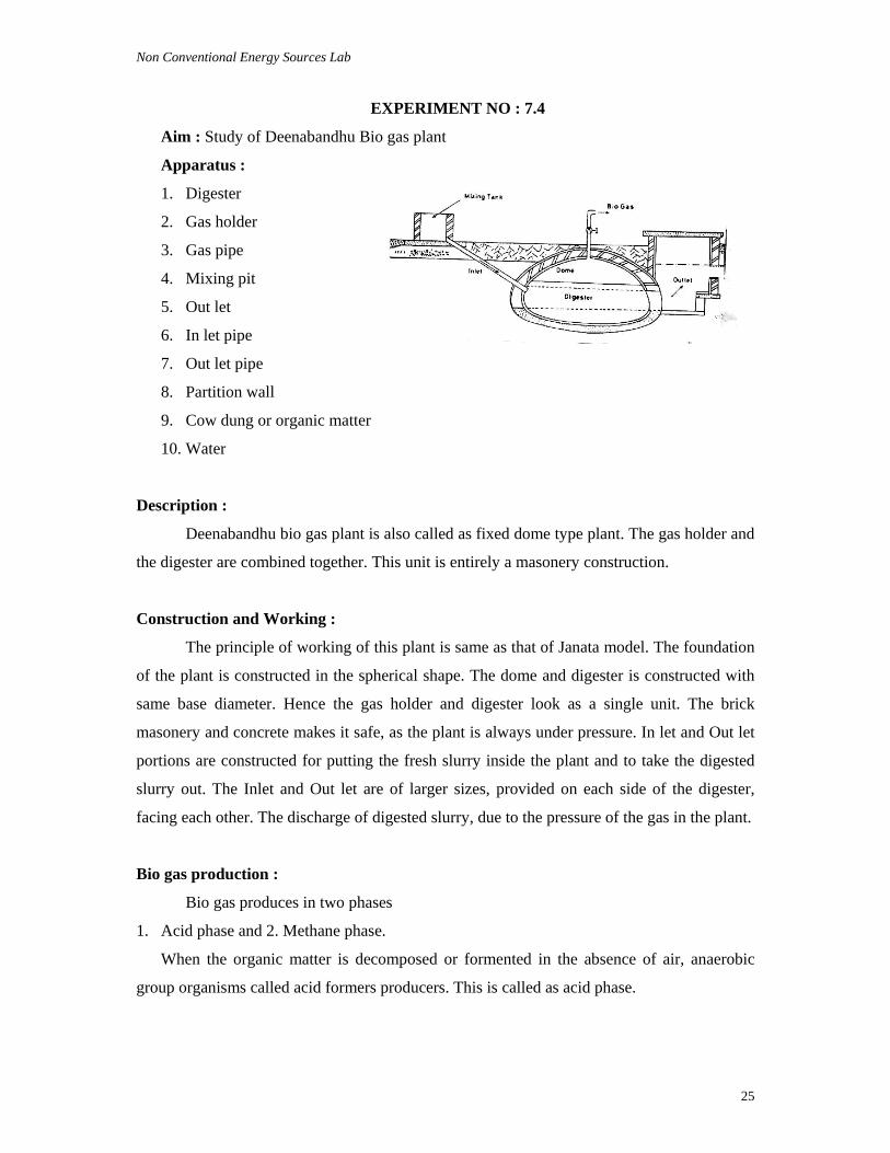
Description :
Deenabandhu bio gas plant is also called as fixed dome type plant. The gas holder and
the digester are combined together. This unit is entirely a masonery construction.
Construction and Working :
The principle of working of this plant is same as that of Janata model. The foundation
of the plant is constructed in the spherical shape. The dome and digester is constructed with
same base diameter. Hence the gas holder and digester look as a single unit. The brick
masonery and concrete makes it safe, as the plant is always under pressure. In let and Out let
portions are constructed for putting the fresh slurry inside the plant and to take the digested
slurry out. The Inlet and Out let are of larger sizes, provided on each side of the digester,
facing each other. The discharge of digested slurry, due to the pressure of the gas in the plant.
Bio gas production :
Bio gas produces in two phases
1. Acid phase and 2. Methane phase.
When the organic matter is decomposed or formented in the absence of air, anaerobic
group organisms called acid formers producers. This is called as acid phase.
Non Conventional Energy Sources Lab
26
The acid former bacterias are then converted in to Methane (CH4) and Carbon-di-
oxide (CO2) after two weeks. The bacterias which are strictly anaerobes are called Methane
former bacterias. The combination of methane and Carbon-di-oxide is known as Bio gas.
The produced Bio gas stored in the gas holder can be utilised by opening the gas pipe
according to our needs.
Data Required to be noted
Name of the Bio gas plant : __________________________________________
Location : __________________________________________
Sl. No.
Date of Feeding Bio Mass
Quantity of Cow Dung
Quantity of Water Mixed
Quantity of Bio Gas
Production
Quantity of Bio Gas
Produced
Non Conventional Energy Sources Lab
27
WIND ENERGY
Experiment No : 8.1
Aim : Study of Horizontal Wind Mill
Apparatus :
1. Induction generator and gear box
2. Blade (Single or Double or Multiblade)
3. Rotor
4. Transmission
5. Tower
Description :
In this, the axis of rotation of wind mill is horizontal. Horizontal axis wind mills are
further classified as single bladed, double bladed and multibladed.
Main components of the wind mill are :
(i). Rotor : It consists of blades. Rotor is mounted on the horizontal shaft and connected to
the generator through transmission with the help of bearings.
(ii). Transmission : It consists of gears, belts, chains, clutches etc., It controls the wind speed
or rotor speed according to the generator speed. When the wind speed is low, the
transmission system increases rotor sped. Similarly when the wind speed high, it decreases
the rotor speed.
(iii). Generator : It generates Electricity
(iv). Tower : Tower is a supporting device. It holds all the parts of wind mill. It is made of
reinforced concrete or Iron poles. The height of the tower depends on the capacity of the
plant.
Non Conventional Energy Sources Lab
28
Question for Evaluation :
After performing the practical task the students are required to answer the
following questions :
Q1. What are the main parts of Horizontal wind mill ?
Ans. 1. Introduction generator and gear box; 2. Hub; 3. Counter Weight; 4. Composite blade;
5. Tower.
Q2. How do you classify wind mills ?
Ans. Wind mills are classified as (a) Horizontal wind mills and (b) Vertical wind mills
Q3. What are caused because of two factors :
(i) The absorption of solar energy on the earth’s surface and in the atmosphere.
(ii) The rotation of the earth about its axis and its motion around the sun
Q4. How wind mill works ?
Ans. A wind mill converts the Kinetic Energy of moving air into mechanical Energy that can
be either used directly to run the machine or to run the generator to produce electricity.
Non Conventional Energy Sources Lab
29
FUEL CELLS
EXPERIMENT NO : 9.1
Aim : Study of Fuel cells.
Apparatus : 1. Hydrogen electrode (Anode)
2. Oxygen electrode (cathode) and
3. An electrolyte
Description :
A cell or combination of cells capable of generating an electric current by converting
the chemical energy of a fuel directly into electrical energy. Fuel cells are efficient and quiet,
operate on a variety of hydrocarbon fuels, and produces almost no objectionable emissions.
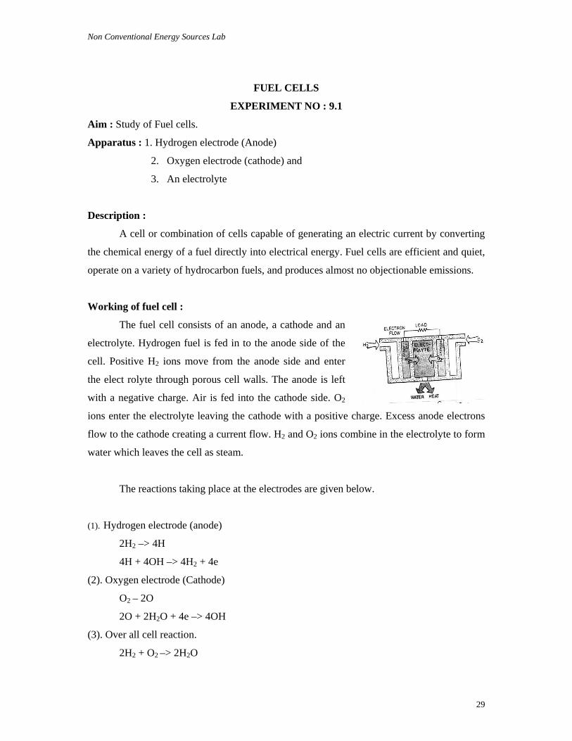
Working of fuel cell :
The fuel cell consists of an anode, a cathode and an
electrolyte. Hydrogen fuel is fed in to the anode side of the
cell. Positive H2 ions move from the anode side and enter
the elect rolyte through porous cell walls. The anode is left
with a negative charge. Air is fed into the cathode side. O2
ions enter the electrolyte leaving the cathode with a positive charge. Excess anode electrons
flow to the cathode creating a current flow. H2 and O2 ions combine in the electrolyte to form
water which leaves the cell as steam.
The reactions taking place at the electrodes are given below.
(1). Hydrogen electrode (anode)
2H2 –> 4H
4H + 4OH –> 4H2 + 4e
(2). Oxygen electrode (Cathode)
O2 – 2O
2O + 2H2O + 4e –> 4OH
(3). Over all cell reaction.
2H2 + O2 –> 2H2O
Non Conventional Energy Sources Lab
30
Questions for Evaluation :
After performing the practical task the students are required to answer the
following questions :
Q1. What are the apparatus required for fuel cells ?
Ans. 1. Hydrogen electrode (Anode)
2. Oxygen electrode (Cathode) and
3. An electrolyte.
Q2. Define fuel cell ?
Ans. A fuel cell is capable of generating an electric current by converting the chemical
energy of a fuel directly into electrical energy.
Q3. Write the chemical reactions which took place at the Hydrogen electrode ?
Ans. 2H2 – 4H
4H + 4OH – 4H2 + 4e
Q3. Write the chemical reactions which took place at the oxygen electrode ?
Ans. O2 – 2O
2O + 2H2O + 4e – 4OH
Q4. Write the overall cell reaction ?
Ans. 2H2 + O2 – 2H2O