non-contact voltage and electric field measurement...
TRANSCRIPT

Centre for Physical Electronics and Quantum Technology
NON-CONTACT VOLTAGE AND ELECTRIC FIELD
MEASUREMENT USING THE ELECTRIC POTENTIAL SENSOR
Centre for Physical Electronics and Quantum Technology,University of Sussex, UK
R.J. Prance A. Aydin S. Beardsmore-Rust M. Nock
C.J. Harland P.B. Stiffell P. Watson D. Smith
H. Prance W.Gebrial S. Mukherjee
J. Skinner
C. Antrobus
Centre for Physical Electronics and Quantum Technology
Outline
•Background to Electric Potential Sensor (EPS) technology
•Performance as non-contact voltage sensor
•Performance as non-contact electric field sensor
•Applications
•Array imaging 1-D and 2-D
•Conclusions

Centre for Physical Electronics and Quantum Technology
Electric Potential Sensor (EPS)
• Behaves like a ‘perfect’ voltmeter• Measures spatial electric potential or electric field• No real current is drawn from the sample (displacement current only)• Non invasive/non contact capacitive measurement• Sample is not loaded by sensor
Specifications (generic)
• Input resistance up to ~ • Input capacitance down to ~ • Voltage noise referred to input < 30nV/ (for >10Hz)• Bandwidth quasi DC to 100MHz
An ultra low noise electric potential probe for human body scanning, R.J. Prance, A. Debray, T.D. Clark, H. Prance, M. Nock, C.J. Harland, A.J. Clippingdale, Meas. Sci. and Tech.,11, 291-297, (2000)
Hz
Ω1810F1710−
Background
Centre for Physical Electronics and Quantum Technology
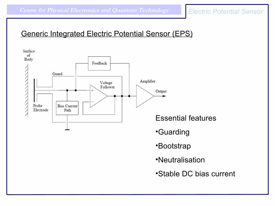
Generic Integrated Electric Potential Sensor (EPS)
Essential features
•Guarding
•Bootstrap
•Neutralisation
•Stable DC bias current
Electric Potential Sensor
Centre for Physical Electronics and Quantum Technology
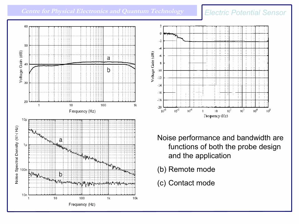
Noise performance and bandwidth are functions of both the probe design and the application
(b) Remote mode
(c) Contact mode
Electric Potential Sensor
Centre for Physical Electronics and Quantum Technology
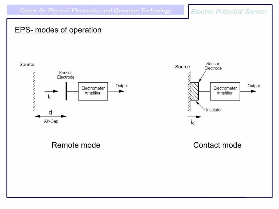
EPS- modes of operation
Remote mode Contact mode
Electric Potential Sensor
Source Source
Centre for Physical Electronics and Quantum Technology
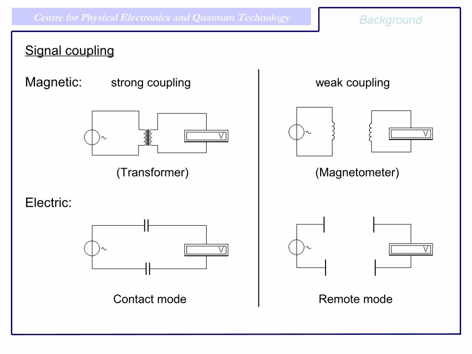
Signal coupling
Magnetic: strong coupling weak coupling
Electric:
Contact mode Remote mode
(Transformer) (Magnetometer)
Background
Centre for Physical Electronics and Quantum Technology
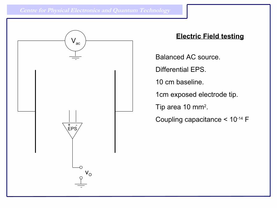
Electric Field testing
Balanced AC source.
Differential EPS.
10 cm baseline.
1cm exposed electrode tip.
Tip area 10 mm2.
Coupling capacitance < 10-14 F
Vac
+ -EPS
vO

Centre for Physical Electronics and Quantum Technology Electric Potential Sensor
Individual EPS frequency response curves.
Combined differential frequency response (preliminary data only)

Centre for Physical Electronics and Quantum Technology Electric Potential Sensor
Noise and minimum detectable signal in agreement.
Corresponds to ~1 mV/m.
Rotating vane E field meters ~ 10 V/m.
Lab based instrument ~ 10 mV/m.
Centre for Physical Electronics and Quantum Technology
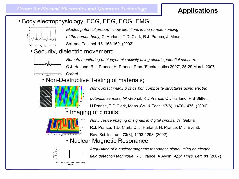
• Body electrophysiology, ECG, EEG, EOG, EMG;Electric potential probes – new directions in the remote sensing
of the human body, C. Harland, T.D. Clark, R.J. Prance, J. Meas.
Sci. and Technol. 13, 163-169, (2002)
• Security, dielectric movement;Remote monitoring of biodynamic activity using electric potential sensors,
C.J. Harland, R.J. Prance, H. Prance, Proc. ‘Electrostatics 2007’, 25-29 March 2007,
Oxford. • Non-Destructive Testing of materials;
Non-contact imaging of carbon composite structures using electric
potential sensors, W Gebrial, R J Prance, C J Harland, P B Stiffell,
H Prance, T D Clark, Meas. Sci & Tech. 17(6), 1470-1476, (2006)• Imaging of circuits;
Noninvasive imaging of signals in digital circuits, W. Gebrial,
R.J. Prance, T.D. Clark, C. J. Harland, H. Prance, M.J. Everitt,
Rev. Sci. Instrum. 73(3), 1293-1298, (2002)• Nuclear Magnetic Resonance;
Acquisition of a nuclear magnetic resonance signal using an electric
field detection technique, R J Prance, A Aydin, Appl. Phys. Lett. 91 (2007)
Applications
Centre for Physical Electronics and Quantum Technology
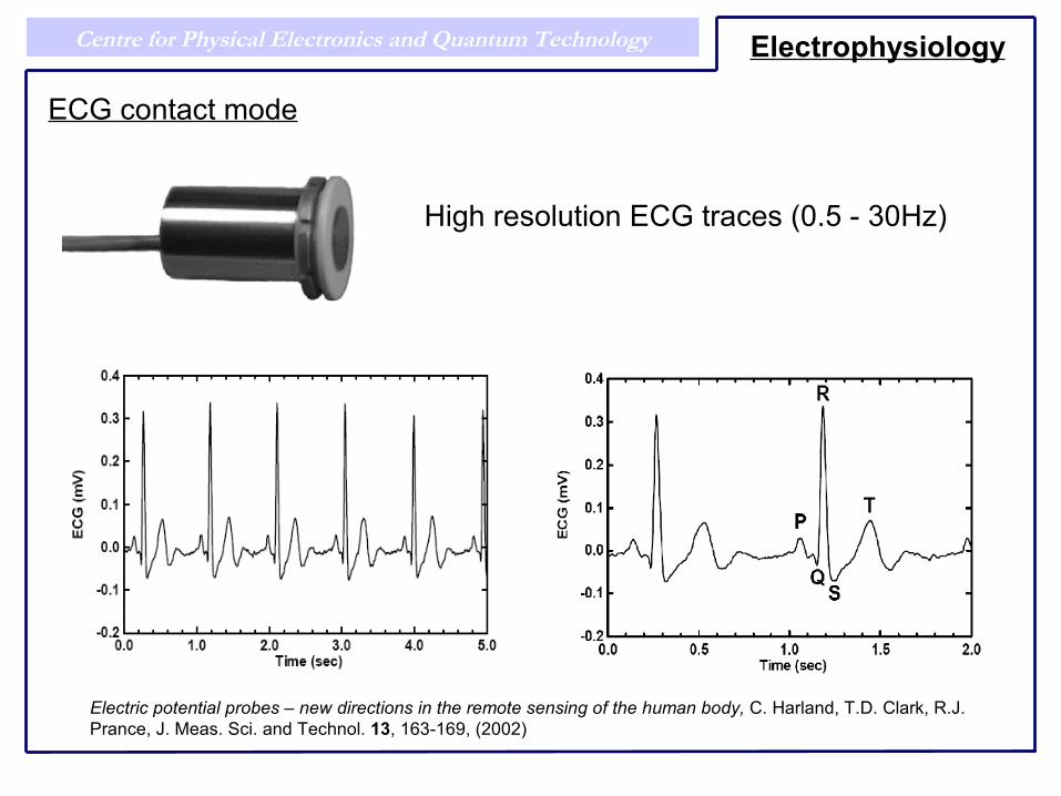
High resolution ECG traces (0.5 - 30Hz)
Electrophysiology
Electric potential probes – new directions in the remote sensing of the human body, C. Harland, T.D. Clark, R.J. Prance, J. Meas. Sci. and Technol. 13, 163-169, (2002)
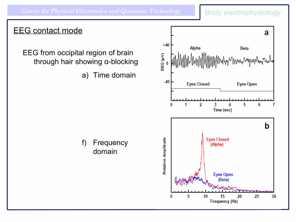
ECG contact mode
Centre for Physical Electronics and Quantum Technology
EEG from occipital region of brain through hair showing α-blocking
a) Time domain
f) Frequency domain
Body electrophysiology
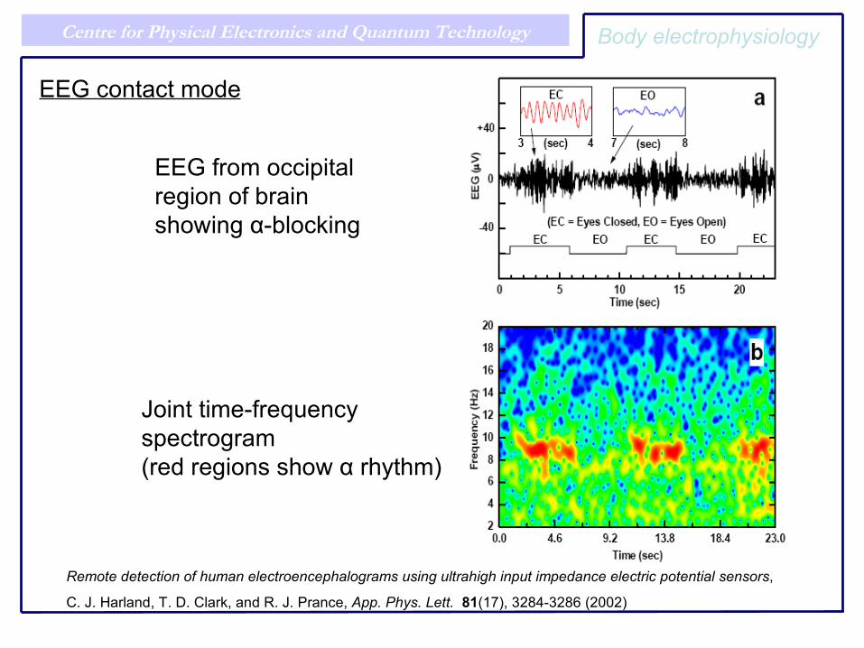
EEG contact mode
Centre for Physical Electronics and Quantum Technology
EEG from occipitalregion of brainshowing α-blocking
Joint time-frequency spectrogram(red regions show α rhythm)
Remote detection of human electroencephalograms using ultrahigh input impedance electric potential sensors, C. J. Harland, T. D. Clark, and R. J. Prance, App. Phys. Lett. 81(17), 3284-3286 (2002)
Body electrophysiology
EEG contact mode

Centre for Physical Electronics and Quantum Technology
Eyeball movement
Applications of Electric Potential (Displacement Current) Sensors in Human Body Electrophysiology, C. J. Harland, T. D.
Clark and R. J. Prance, Proc. 3rd World Congress on Industrial Process Tomography, Banff, Canada, 485-490, (2003)
Body electrophysiology
EOG contact mode
Eyelid movement
Centre for Physical Electronics and Quantum Technology
Electric potential probes – new directions in the remote sensing of the human body, C. Harland, T.D. Clark, R.J. Prance, J. Meas. Sci. and Technol. 13, 163-169, (2002)
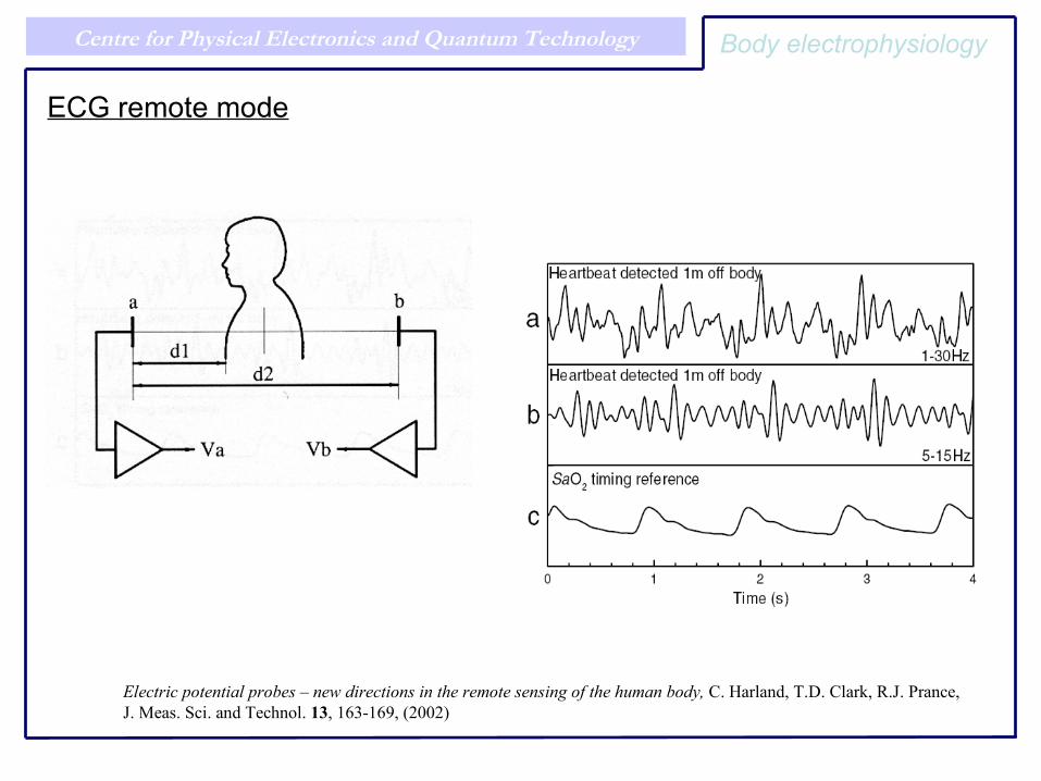
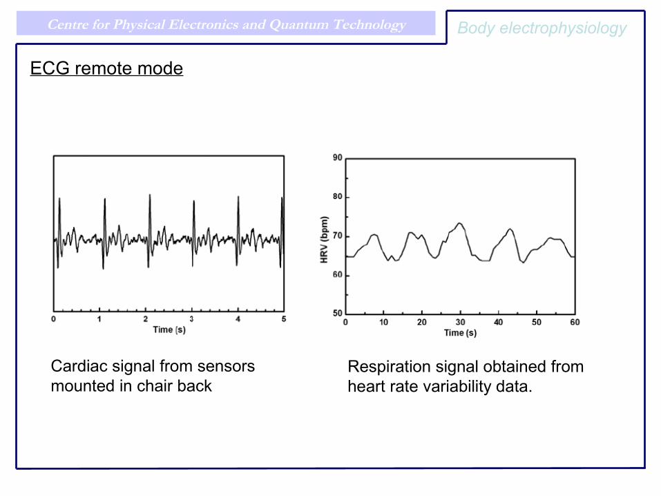
ECG remote mode
Body electrophysiology
Centre for Physical Electronics and Quantum Technology Body electrophysiology
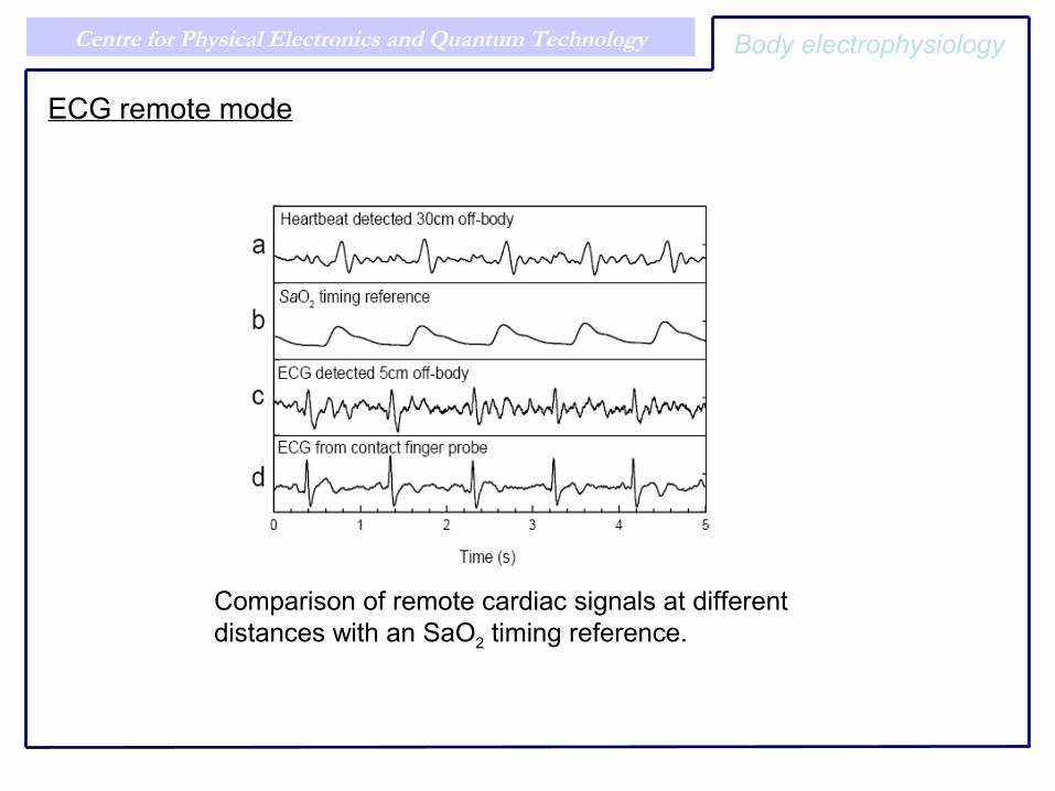
ECG remote mode
Comparison of remote cardiac signals at different distances with an SaO2 timing reference.
Centre for Physical Electronics and Quantum Technology
Cardiac signal from sensors mounted in chair back
ECG remote mode
Respiration signal obtained from heart rate variability data.
Body electrophysiology
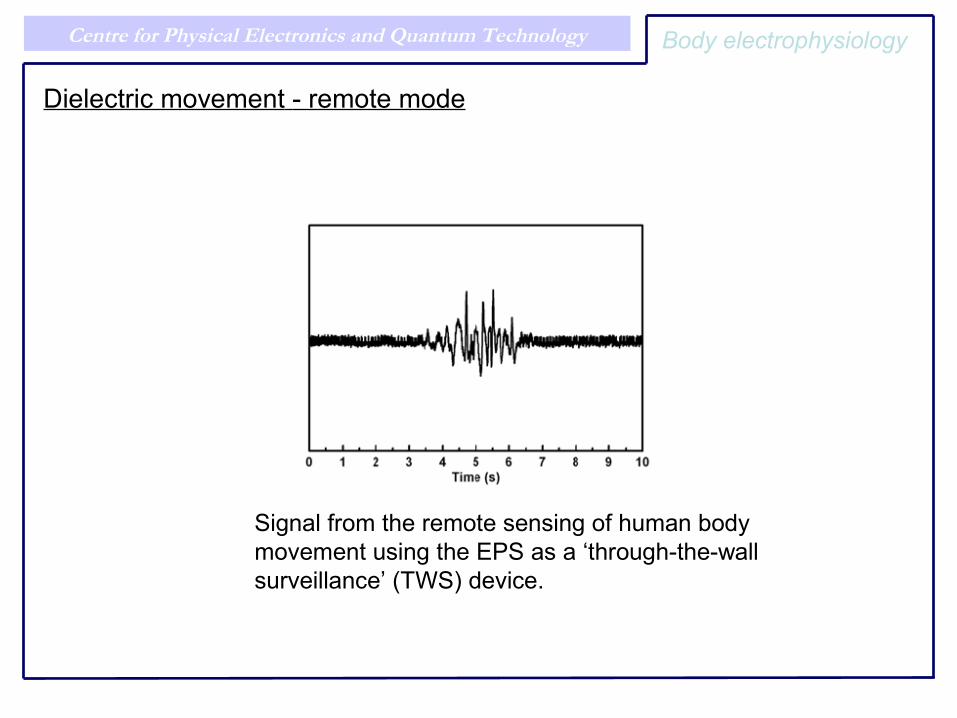
Centre for Physical Electronics and Quantum Technology Body electrophysiology
Dielectric movement - remote mode
Signal from the remote sensing of human body movement using the EPS as a ‘through-the-wallsurveillance’ (TWS) device.
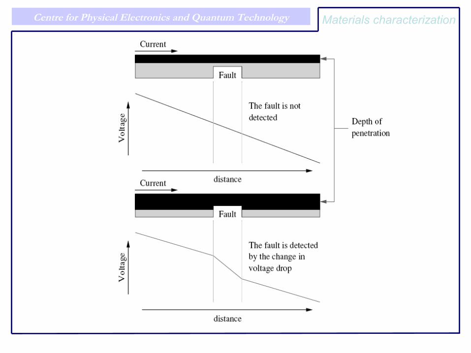
Centre for Physical Electronics and Quantum Technology Materials characterization
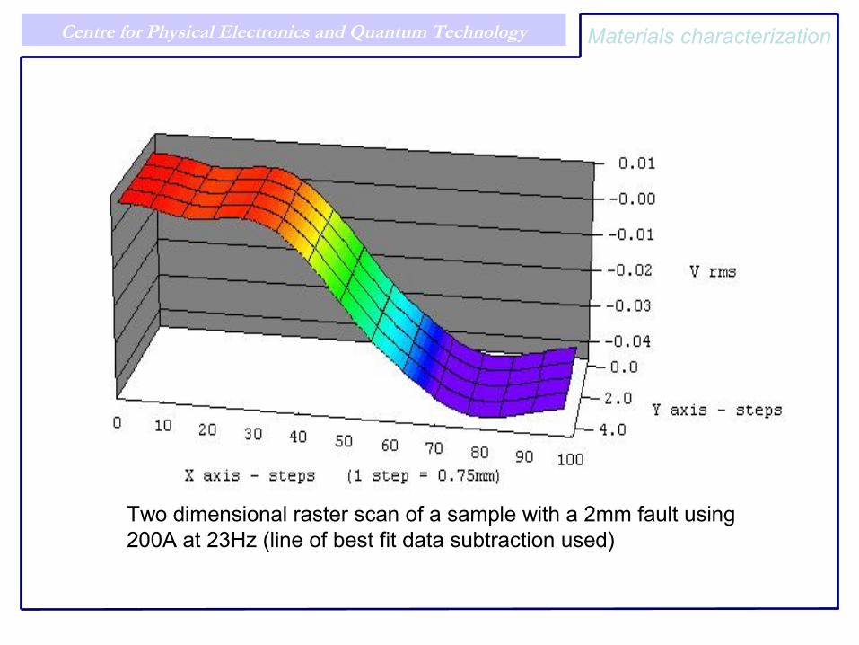
Centre for Physical Electronics and Quantum Technology
Two dimensional raster scan of a sample with a 2mm fault using 200A at 23Hz (line of best fit data subtraction used)
Materials characterization
Centre for Physical Electronics and Quantum Technology
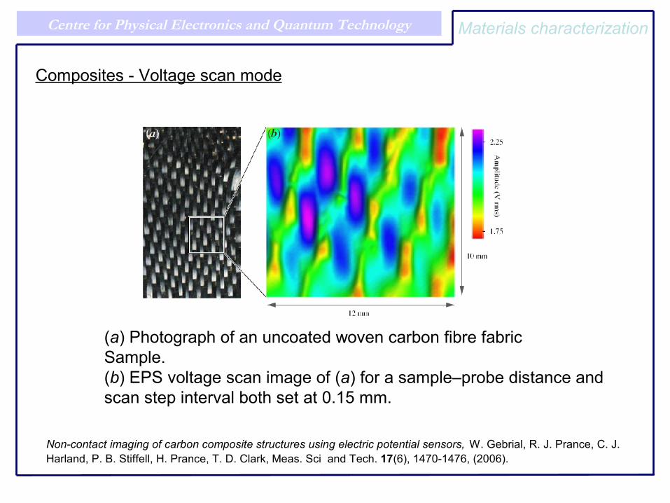
(a) Photograph of an uncoated woven carbon fibre fabricSample.(b) EPS voltage scan image of (a) for a sample–probe distance andscan step interval both set at 0.15 mm.
Non-contact imaging of carbon composite structures using electric potential sensors, W. Gebrial, R. J. Prance, C. J. Harland, P. B. Stiffell, H. Prance, T. D. Clark, Meas. Sci and Tech. 17(6), 1470-1476, (2006).
Materials characterization
Composites - Voltage scan mode
Technique for determining the internal integrity of composite laminates, Prance RJ, Antrobus C, invited talk, NAFEMS 2006 conference, 14-15 June 2006, Crewe Hall, Cheshire
Centre for Physical Electronics and Quantum Technology
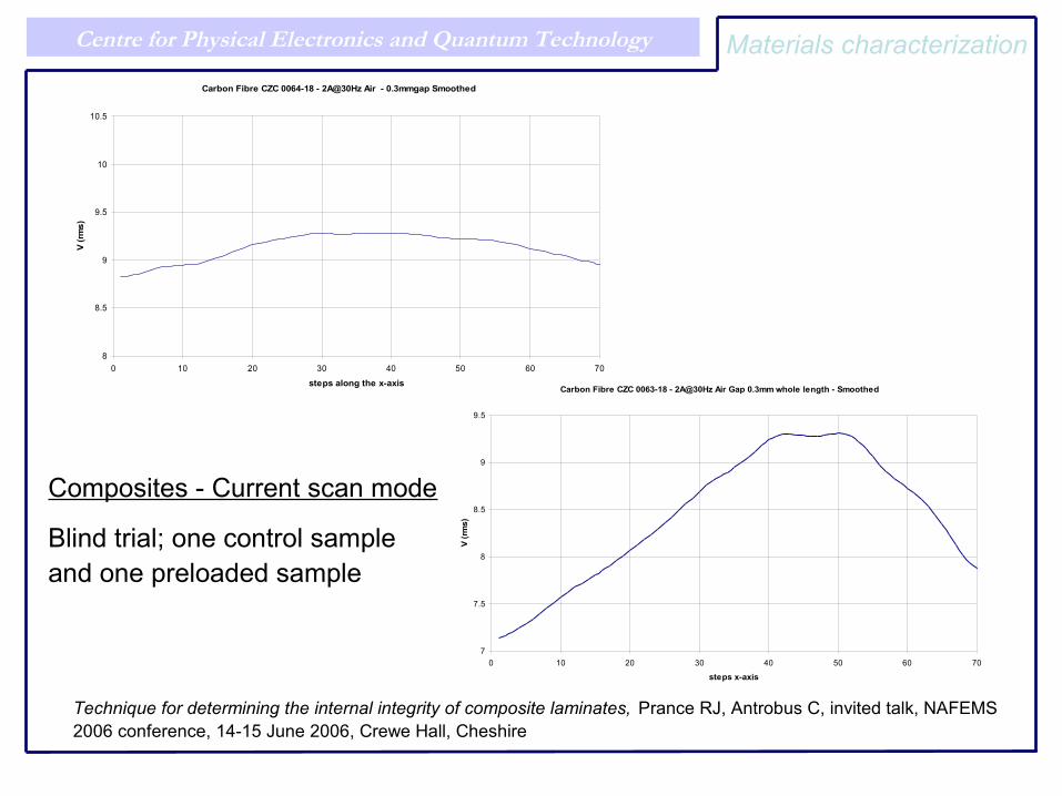
Carbon Fibre CZC 0064-18 - 2A@30Hz Air - 0.3mmgap Smoothed
8
8.5
9
9.5
10
10.5
0 10 20 30 40 50 60 70
steps along the x-axis
V (r
ms)
Composites - Current scan mode
Blind trial; one control sample and one preloaded sample
Carbon Fibre CZC 0063-18 - 2A@30Hz Air Gap 0.3mm whole length - Smoothed
7
7.5
8
8.5
9
9.5
0 10 20 30 40 50 60 70
steps x-axis
V (r
ms)
Materials characterization
Centre for Physical Electronics and Quantum Technology
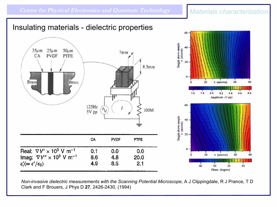
Insulating materials - dielectric properties
Non-invasive dielectric measurements with the Scanning Potential Microscope, A J Clippingdale, R J Prance, T D Clark and F Brouers, J Phys D 27, 2426-2430, (1994)
Materials characterization
Centre for Physical Electronics and Quantum Technology
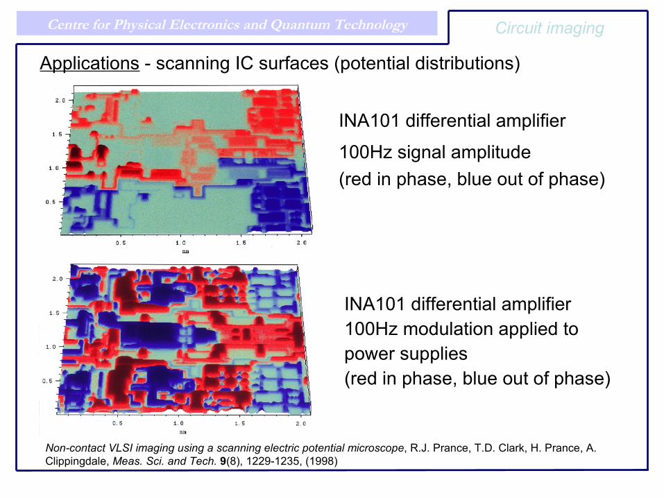
Applications - scanning IC surfaces (potential distributions)
INA101 differential amplifier
100Hz signal amplitude(red in phase, blue out of phase)
INA101 differential amplifier100Hz modulation applied to power supplies(red in phase, blue out of phase)
Non-contact VLSI imaging using a scanning electric potential microscope, R.J. Prance, T.D. Clark, H. Prance, A. Clippingdale, Meas. Sci. and Tech. 9(8), 1229-1235, (1998)
Circuit imaging
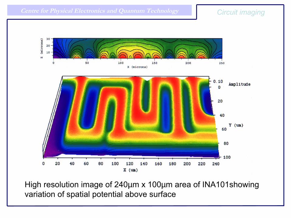
Centre for Physical Electronics and Quantum Technology
High resolution image of 240µm x 100µm area of INA101showing variation of spatial potential above surface
Circuit imaging
Centre for Physical Electronics and Quantum Technology
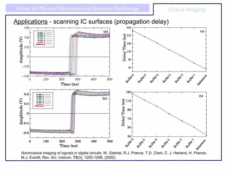
Applications - scanning IC surfaces (propagation delay)
Noninvasive imaging of signals in digital circuits, W. Gebrial, R.J. Prance, T.D. Clark, C. J. Harland, H. Prance, M.J. Everitt, Rev. Sci. Instrum. 73(3), 1293-1298, (2002)
Circuit imaging
Centre for Physical Electronics and Quantum Technology
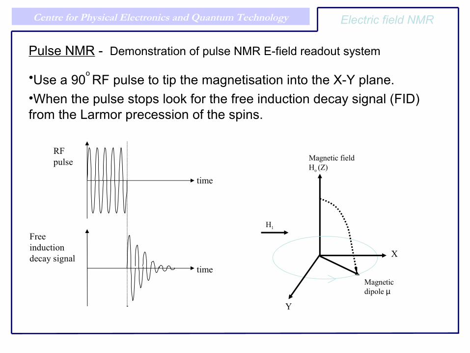
Pulse NMR - Demonstration of pulse NMR E-field readout system
•Use a 90o RF pulse to tip the magnetisation into the X-Y plane.•When the pulse stops look for the free induction decay signal (FID) from the Larmor precession of the spins.
RF pulse
time
time
Free induction decay signal X
Magnetic dipole µ
H1
Magnetic field Ho (Z)
Y
Electric field NMR

Centre for Physical Electronics and Quantum Technology
0 1x10⁶ 2x10⁶ 3x10⁶ 4x10⁶ 5x10610-16
10-15
10-14
10-13
10-12
10-11
10-10
10-9
10-8
10-7
Frequency (Hz)
Pow
er
NMR results - frequency domain
Electric field NMR
Electric field NMR a new technique, R. J.Prance, A. Aydin et al, EUROMAR conf., 16-21 July 2006, York
Centre for Physical Electronics and Quantum Technology
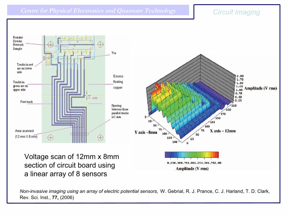
Voltage scan of 12mm x 8mm section of circuit board using a linear array of 8 sensors
Non-invasive imaging using an array of electric potential sensors, W. Gebrial, R. J. Prance, C. J. Harland, T. D. Clark, Rev. Sci. Inst., 77, (2006)
Circuit imaging
Centre for Physical Electronics and Quantum Technology
• Non-contact potential and electric field sensing demonstrated.
• Wide range of applications already at proof of principle stage.
• Enhanced sensors under development.
• 1-D and 2-D arrays now operational.
• Technology moving to commercialisation with partners.
Conclusions
Centre for Physical Electronics and Quantum Technology
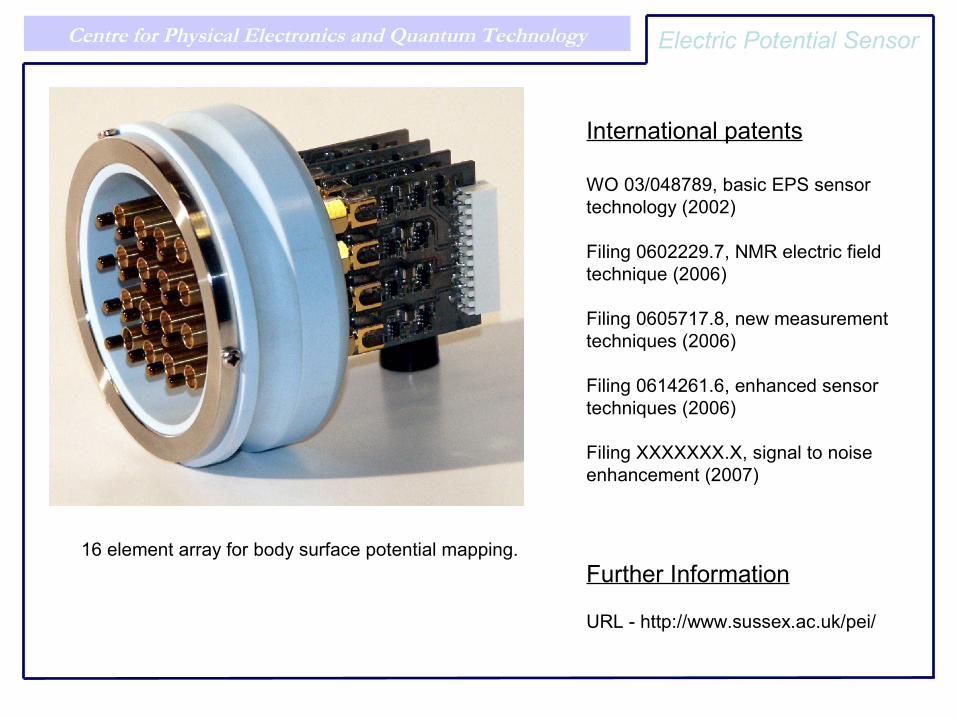
16 element array for body surface potential mapping.
Electric Potential Sensor
International patents
WO 03/048789, basic EPS sensor technology (2002)
Filing 0602229.7, NMR electric field technique (2006)
Filing 0605717.8, new measurement techniques (2006)
Filing 0614261.6, enhanced sensor techniques (2006)
Filing XXXXXXX.X, signal to noise enhancement (2007)
Further Information
URL - http://www.sussex.ac.uk/pei/