noise and vibration control
DESCRIPTION
Noise and Vibration of Flow in Pipes.Noise from pipes and ducts is important not only in many industrial sectors but also in residential buildingsSound generated by fluid flow in pipes can propagate as fluid-borne sound or structure-borne.TRANSCRIPT
Indian Institute of Technology Roorkee
Noise and Vibration Control
7. NOISE AND VIBRATION OF FLOW IN PIPES
Noise from pipes and ducts is important not only in many industrial sectors but also in residential buildings.
Sound generated by fluid flow in pipes can propagate as fluid-borne sound or structure-borne.
It may also radiate directly from openings or pipe walls or by connected structural components.
Indian Institute of Technology Roorkee
Noise and Vibration Control
7.1 General description of the effect of flow disturbances on pipeline and ducts noise and vibration
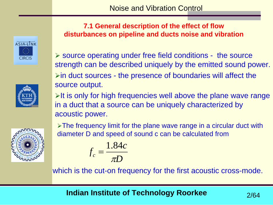
source operating under free field conditions - the source strength can be described uniquely by the emitted sound power.
in duct sources - the presence of boundaries will affect the source output.
It is only for high frequencies well above the plane wave range in a duct that a source can be uniquely characterized by acoustic power.
The frequency limit for the plane wave range in a circular duct with diameter D and speed of sound c can be calculated from
which is the cut-on frequency for the first acoustic cross-mode. D
cfc π84.1
=
2/64

Indian Institute of Technology Roorkee
Noise and Vibration Control
7.2 Turbulent boundary layer and control valve sound generation
An important sound source is the turbulent boundary layer flow. The interaction with the pipe wall gives sound generation of dipole character. The internal sound power is determined by :
SMUKW DD33ρ=
510122 −×−≈DKWhere , U is the flow speed, ρ is the density, M is the Mach-number and S is the pipe cross section area.
3/64
Indian Institute of Technology Roorkee
Noise and Vibration Control
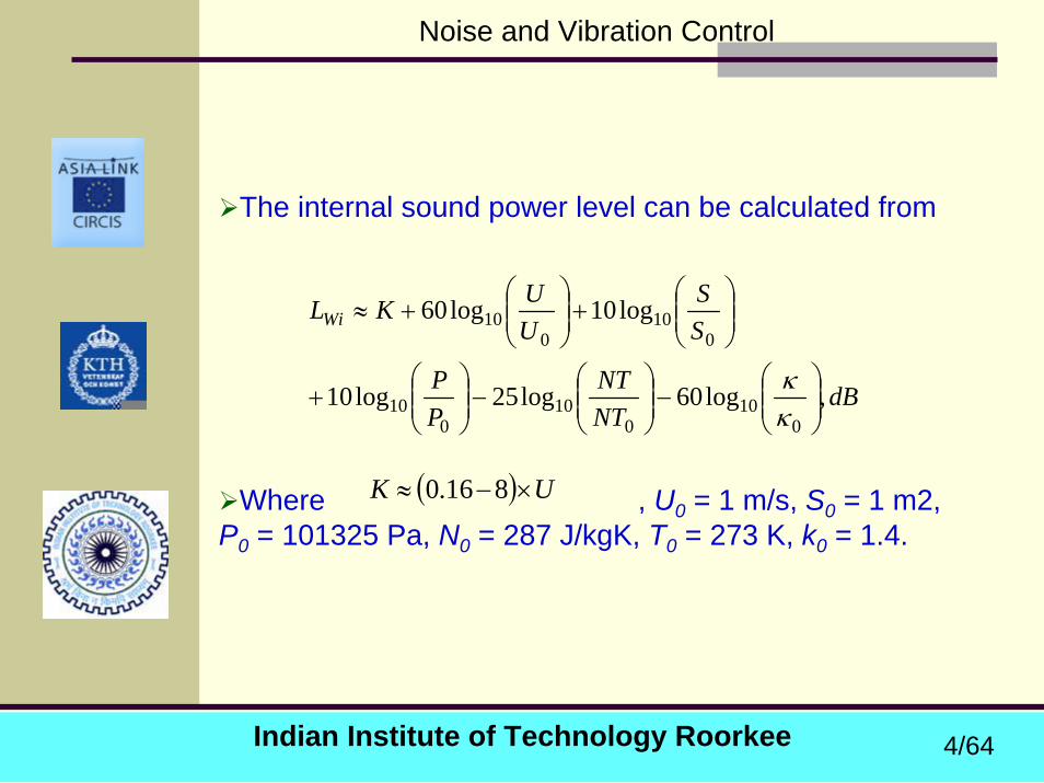
The internal sound power level can be calculated from
Where , U0 = 1 m/s, S0 = 1 m2, P0 = 101325 Pa, N0 = 287 J/kgK, T0 = 273 K, k0 = 1.4.
dBNTNT
PP
SS
UUKLWi
,log60log25log10
log10log60
010
010
010
010
010
⎟⎟⎠
⎞⎜⎜⎝
⎛−⎟⎟
⎠
⎞⎜⎜⎝
⎛−⎟⎟
⎠
⎞⎜⎜⎝
⎛+
⎟⎟⎠
⎞⎜⎜⎝
⎛+⎟⎟
⎠
⎞⎜⎜⎝
⎛+≈
κκ
( ) UK ×−≈ 816.0
4/64
Indian Institute of Technology Roorkee
Noise and Vibration Control
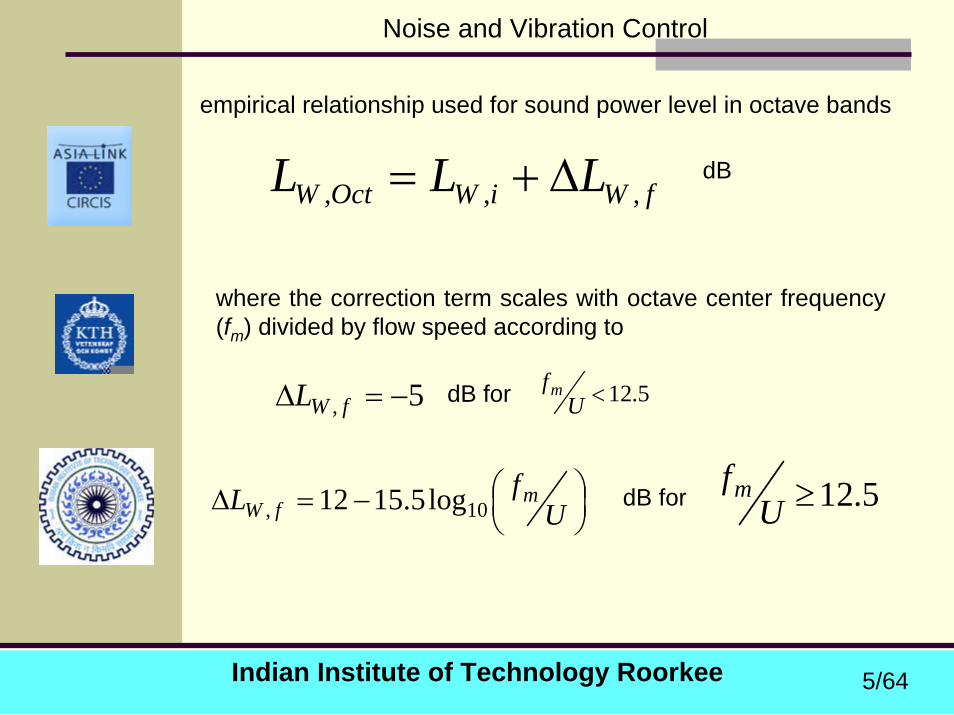
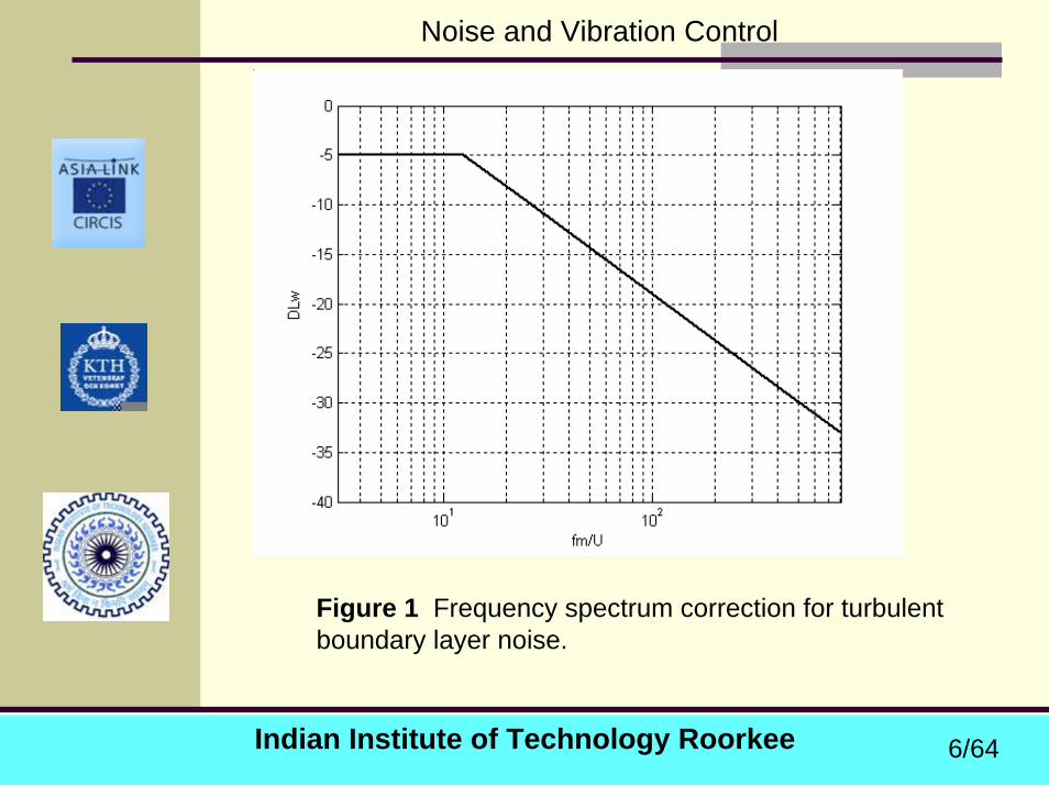
empirical relationship used for sound power level in octave bands
fWiWOctW LLL ,,, ∆+=
where the correction term scales with octave center frequency (fm) divided by flow speed according to
dB
5, −=∆ fWL dB for 5.12<Ufm
⎟⎠⎞⎜
⎝⎛−=∆ U
fL mfW 10, log5.1512 5.12≥U
fmdB for
5/64
Indian Institute of Technology Roorkee
Noise and Vibration Control
Figure 1 Frequency spectrum correction for turbulent boundary layer noise.
6/64
Indian Institute of Technology Roorkee
Noise and Vibration Control
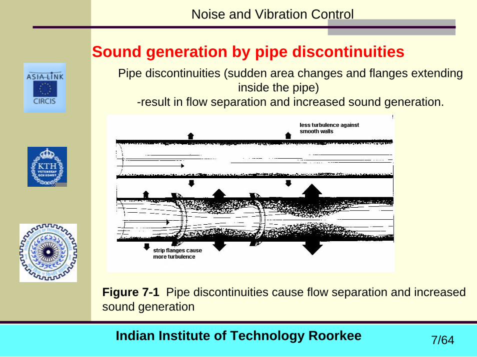
Sound generation by pipe discontinuitiesPipe discontinuities (sudden area changes and flanges extending
inside the pipe)-result in flow separation and increased sound generation.
Figure 7-1 Pipe discontinuities cause flow separation and increased sound generation
7/64
Indian Institute of Technology Roorkee
Noise and Vibration Control
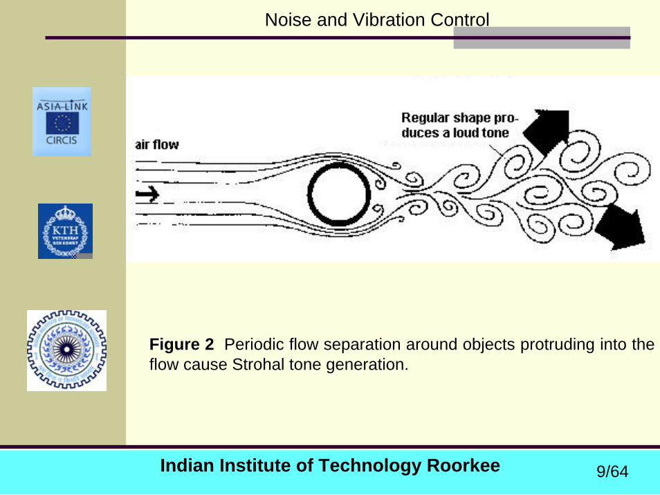
Objects such as gratings, struts or metering devices projecting into the flow can lead to periodic pressure fluctuations which can cause tonal sound generation (Strohaltones).
The frequency limit for the plane wave range in a circular duct with diameter D and speed of sound c can be calculated from
where U is the flow speed, d is a typical cross dimension of the object and St is the Strouhal number which will take on different values depending on the geometry.
dUStf =
8/64
Indian Institute of Technology Roorkee
Noise and Vibration Control
Figure 2 Periodic flow separation around objects protruding into the flow cause Strohal tone generation.
9/64
Indian Institute of Technology Roorkee
Noise and Vibration Control
Control valve sound generation
These devices serve several purposes from the basic to start and stop a flow to regulation of flow rates and pressures.
In particular at high flow rates and high pressure drop ratios across a flow regulator, large in-duct sound powers can be created exciting vibrations in the surrounding pipe structure and associated high levels of radiated sound.
10/64
Indian Institute of Technology Roorkee
Noise and Vibration Control
Classification of valves
Classification based on the mode of operation:Stop valves - used to shut off or partially shut off the
flow of fluid.Check valves -non-return valves (allows flow in one
direction only)Besides stop and check valves a number of other
operating modes exist mainly related to the control of pressure or flow rate (throttling).
Concerning the valve design all valves can be split into the following main parts: the body, the plug, the seat and the stem.
11/64
Indian Institute of Technology Roorkee
Noise and Vibration Control
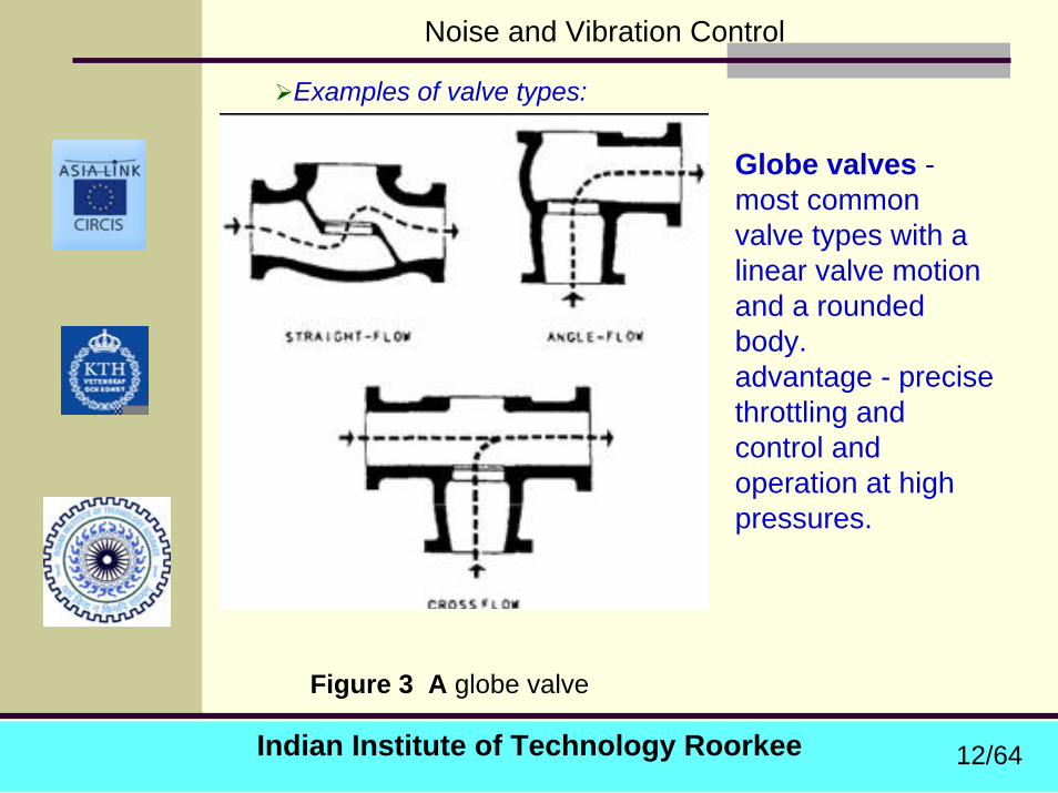
Examples of valve types:
Globe valves -most common valve types with a linear valve motion and a rounded body. advantage - precise throttling and control and operation at high pressures.
Figure 3 A globe valve
12/64
Indian Institute of Technology Roorkee
Noise and Vibration Control
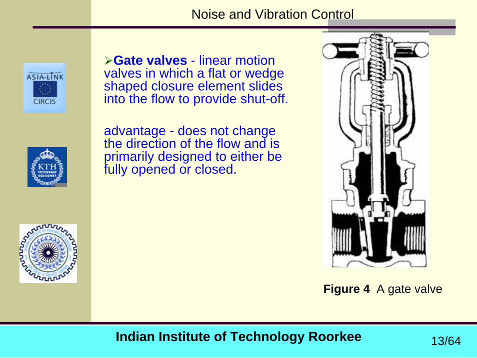
Gate valves - linear motion valves in which a flat or wedge shaped closure element slides into the flow to provide shut-off.
advantage - does not change the direction of the flow and is primarily designed to either be fully opened or closed.
Figure 4 A gate valve
13/64
Indian Institute of Technology Roorkee
Noise and Vibration Control
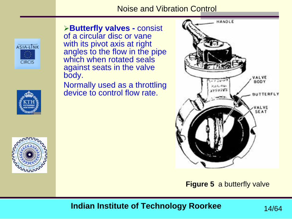
Butterfly valves - consist of a circular disc or vane with its pivot axis at right angles to the flow in the pipe which when rotated seals against seats in the valve body. Normally used as a throttling device to control flow rate.
Figure 5 a butterfly valve
14/64
Indian Institute of Technology Roorkee
Noise and Vibration Control
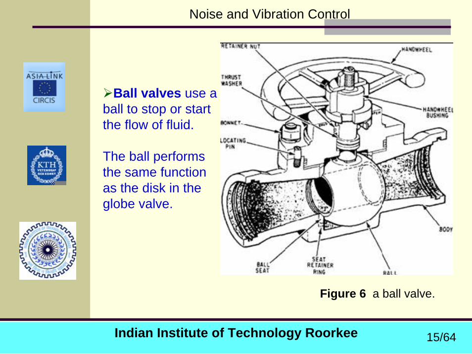
Ball valves use a ball to stop or start the flow of fluid.
The ball performs the same function as the disk in the globe valve.
Figure 6 a ball valve.
15/64
Indian Institute of Technology Roorkee
Noise and Vibration Control
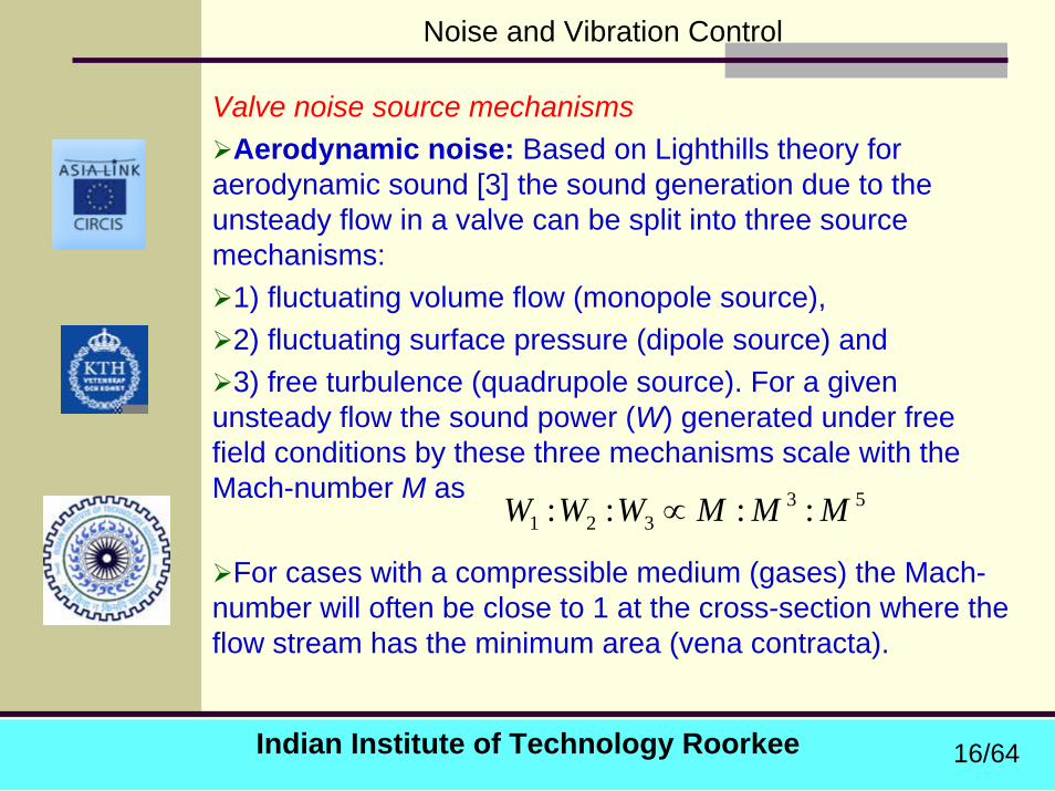
Valve noise source mechanismsAerodynamic noise: Based on Lighthills theory for
aerodynamic sound [3] the sound generation due to the unsteady flow in a valve can be split into three source mechanisms:
1) fluctuating volume flow (monopole source), 2) fluctuating surface pressure (dipole source) and 3) free turbulence (quadrupole source). For a given
unsteady flow the sound power (W) generated under free field conditions by these three mechanisms scale with the Mach-number M as
For cases with a compressible medium (gases) the Mach-number will often be close to 1 at the cross-section where the flow stream has the minimum area (vena contracta).
53321 :::: MMMWWW ∝
16/64

Indian Institute of Technology Roorkee
Noise and Vibration Control
sound radiation from cavitation bubbles Such bubbles arise in a flowing liquid when the local
pressure is so low that it approaches the liquid’s vaporpressure;
A cavitation bubble is unstable, and normally implodes shortly after it is generated.
That implosion is a strong source of sound, however, because it occurs in a very short span of time,
and the sudden local change in volume yields a high value of the volume flow rate Q ~ d(DV)/dt , where DV is the volume of the bubble before collapse.
The sound generated by the imploding cavitation bubbles can be described using the monopole model. Poorly designed valves are examples of that type of sound generation.
Indian Institute of Technology Roorkee
Noise and Vibration Control
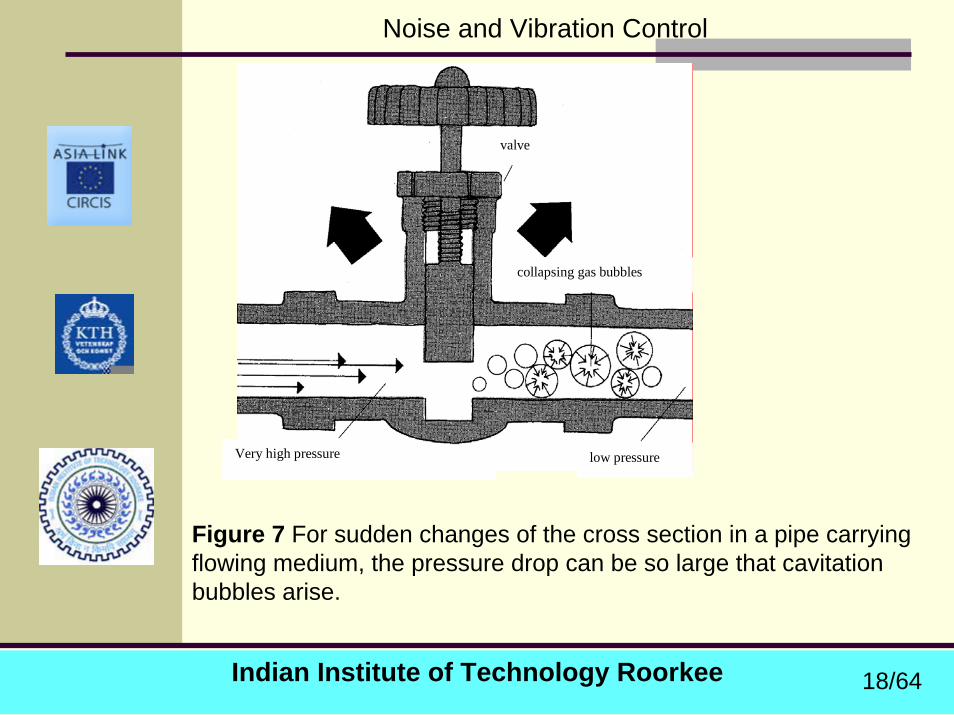
valve
collapsing gas bubbles
low pressure Very high pressure
Figure 7 For sudden changes of the cross section in a pipe carrying flowing medium, the pressure drop can be so large that cavitation bubbles arise.
18/64
Indian Institute of Technology Roorkee
Noise and Vibration Control
Hydrodynamic noise:
For cases with an “incompressible” medium (liquids) the Mach-number is normally very small and it can be expected that the monopole type of mechanism will dominate.
In liquids there is also the possibility for cavitation, i.e., the creation of vapor filled bubbles which implode and represent a monopole source.
The rapid collapse of the bubbles can create very high local pressure peaks with levels up to 1010 Pa that can result in mechanical damage.
When the flow is accelerated towards the vena contracta of a valve, the speed increases and the static pressure drops in accordance with Bernoullis equation.
19/64
Indian Institute of Technology Roorkee
Noise and Vibration Control
Cavitation starts when the local static pressure reaches a certain critical limit Pcr, the value of which depends on the temperature and the amount of solved gas in the liquid.
The minimum value for the critical pressure is the vapor pressure in the liquid Pv.
To describe the cavitation process a cavitation number can be introduced
where P1 is the upstream static pressure, Pv the vapor pressure, ρ the density and U1 the upstream flow speed.
212
11
UPP v
ρσ
−=
20/64
Indian Institute of Technology Roorkee
Noise and Vibration Control
For a given valve this corresponds to a certain upstream flow speed and a critical cavitation number σcr.
A further decrease in the downstream pressure will create higher flow speeds and a further reduction in the cavitation number.
The more the solved gas content increase the larger the critical cavitation number becomes.
The main alternatives to reduce the value of σcr are to reduce the temperature to lower the vapor pressure, degas the liquid and increase the static pressure in the system.
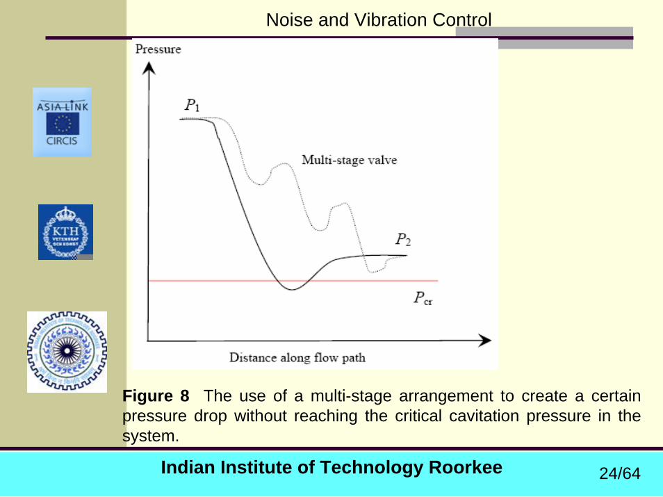
Also use of a too narrow vena contracta section should be avoided by for instance using a multiple stage valve arrangement to create the necessary total pressure drop.
21/64
Indian Institute of Technology Roorkee
Noise and Vibration Control
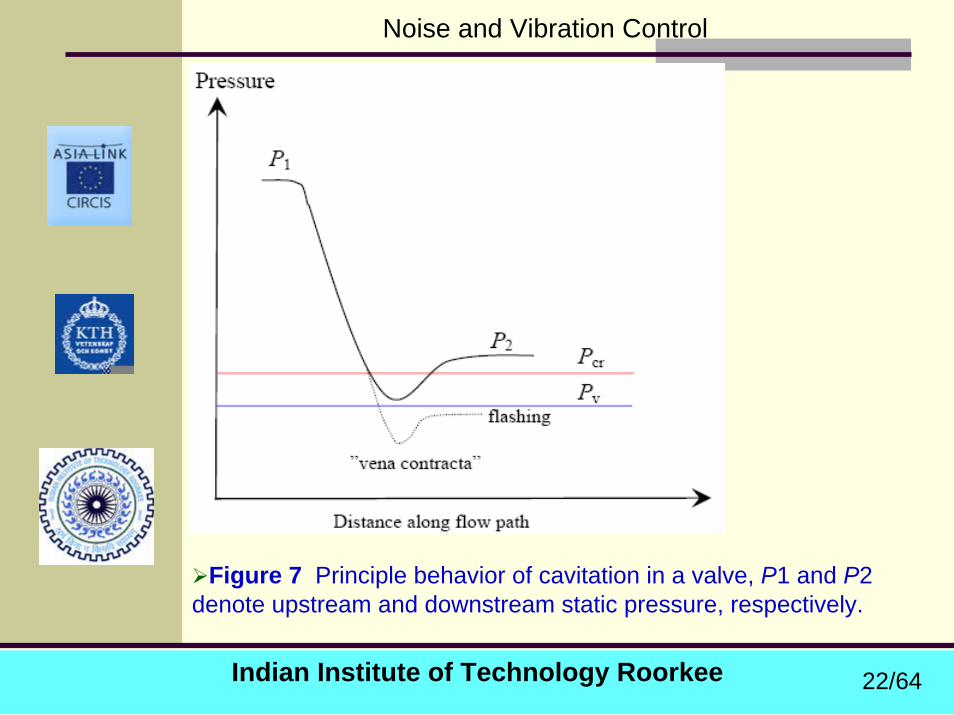
Figure 7 Principle behavior of cavitation in a valve, P1 and P2 denote upstream and downstream static pressure, respectively.
22/64

Indian Institute of Technology Roorkee
Noise and Vibration Control
When the minimum static pressure is less than a certain critical value (Pcr) cavitation starts.
When the downstream pressure P2 is less than the vapor pressure a phenomenon called “flashing” can occur.
For σ < σcr the emitted sound increases rapidly and reaches a maximum at σmax after which it drops.
This corresponds to the region where single bubble cavitation dominates the noise production.
Concerning the spectrum created by cavitation noise it is broadband with a peak corresponding to the dominating size of the imploding bubbles.
23/64
Indian Institute of Technology Roorkee
Noise and Vibration Control
Figure 8 The use of a multi-stage arrangement to create a certain pressure drop without reaching the critical cavitation pressure in the system.
24/64
Indian Institute of Technology Roorkee
Noise and Vibration Control
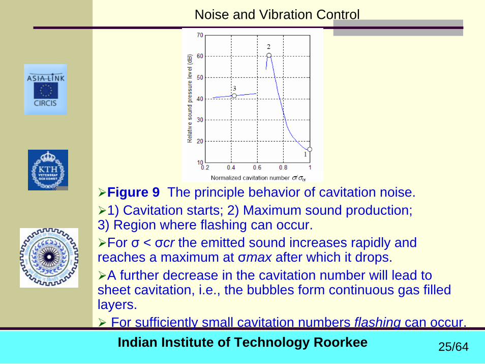
Figure 9 The principle behavior of cavitation noise. 1) Cavitation starts; 2) Maximum sound production;
3) Region where flashing can occur.For σ < σcr the emitted sound increases rapidly and
reaches a maximum at σmax after which it drops. A further decrease in the cavitation number will lead to
sheet cavitation, i.e., the bubbles form continuous gas filled layers.
For sufficiently small cavitation numbers flashing can occur.
25/64
Indian Institute of Technology Roorkee
Noise and Vibration Control
Mechanical noise: This normally originates from the valve plug and is mainly a
problem in liquid filled systems.water hammer:created by the rapid closing of a stop valve. This creates a travelling pressure wave (“shock wave”) with
amplitude of the order of
where ρ is the density, c the speed of sound and U the mean flow speed. For the case of water this can easily produce pressure peaks of the order of 106-7 Pa which can lead to noise problems and mechanical damage.
cUp ρ∝maxˆ
26/64
Indian Institute of Technology Roorkee
Noise and Vibration Control
To reduce the effect of water hammers--special designs of the valve seat or body can be used -the upstream pipe can be fitted with a flexible section or expansion tank which can absorb the pressure pulse.
In high pressure steam power plants so called condensed steam water hammers are created.
This is potentially very dangerous since very high pressure loads can result that can blow up a pipe wall and cause serious accidents.
27/64
Indian Institute of Technology Roorkee
Noise and Vibration Control
VALVE SCREECHAnother mechanism is periodic flow separation creating fluctuating
fluid forces which excite structural vibrations in the valve plug & stem, e.g., bending modes.
A particular dangerous situation is when a periodic flow phenomenon around the valve plug, characterized by a Strouhal-frequency fSt, is close to a structural eigenfrequency fMek.
This can create a self-sustained oscillator which means that the two phenomena form a positive feed-back loop, where energy from the mean flow is fed into the structural eigenfrequency.
A growing oscillation at a dominating frequency will then by created limited in amplitude only by losses or non-linear effects
phenomenon is called valve screech and can create very high vibration amplitudes with risk for mechanical failure as well as high emitted noise levels.
Screech can also be created by interaction between an acousticalmode in the pipe system and a structural valve mode.
To eliminate valve screech there exist two main alternatives:i) to disturb or reduce the amplitude of the periodic flow
phenomenon at the valve plug; ii) to damp or move (change mass/stiffness/length) the mechanical
eigenfrequency.
28/64
Indian Institute of Technology Roorkee
Noise and Vibration Control
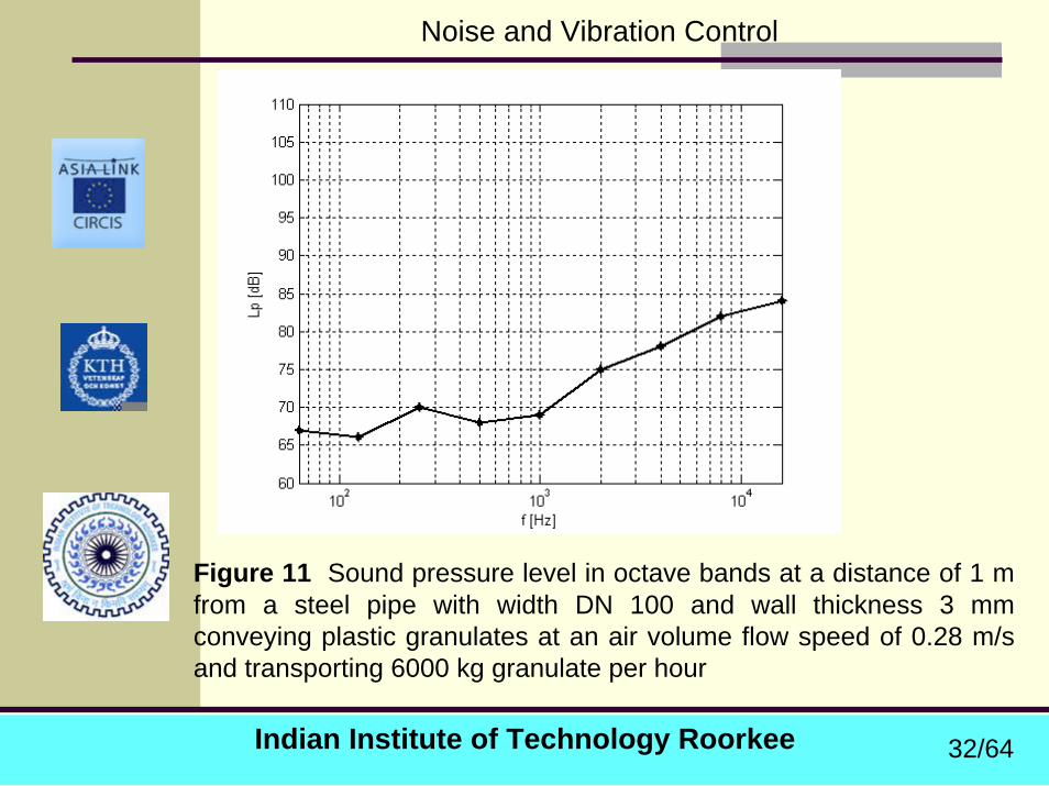
Sound generation by solids in the fluid
Additional noise is created by contact of particles with the pipe wall and with each other.
The noise spectrum is of high frequency character with a maximum typically between 2 kHz and 16 kHz.
The sound pressure level depends on the flow rate, the pipe material and the type of solid transported.
For conveyance of plastic granulates experience has shown that the A-weighted sound level can be 85 dB(A) and 100 dB(A) at a distance of 1m from a straight pipe section.
29/64
Indian Institute of Technology Roorkee
Noise and Vibration Control
When coal is conveyed in water the resulting sound generation will depend on parameters such as:
particle size, concentration of solids, pipe internal diameter as well as on flow speed.
Common flow speeds are 1-6 m/s and solid concentration 0.3-0.6 kg/dm3.
Example:for a pipe with 0.3 m diameter and flow speed 4
m/s the measured sound level at a distance of 0.2 m was 69-72 dB(A).
30/64
Indian Institute of Technology Roorkee
Noise and Vibration Control
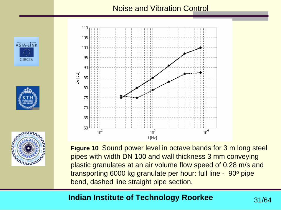
Figure 10 Sound power level in octave bands for 3 m long steel pipes with width DN 100 and wall thickness 3 mm conveying plastic granulates at an air volume flow speed of 0.28 m/s and transporting 6000 kg granulate per hour: full line - 90o pipe bend, dashed line straight pipe section.
31/64
Indian Institute of Technology Roorkee
Noise and Vibration Control
Figure 11 Sound pressure level in octave bands at a distance of 1 m from a steel pipe with width DN 100 and wall thickness 3 mm conveying plastic granulates at an air volume flow speed of 0.28 m/sand transporting 6000 kg granulate per hour
32/64

Indian Institute of Technology Roorkee
Noise and Vibration Control
7-3 Sound Transmission In Pipes and sound radiation from pipes
Sound Transmission In Pipes -through the fluid, liquid or gas,
or through the pipe wall
Fluid-borne sound:Sound propagates as longitudinal waves in fluids. Depending on the relationship between the acoustic
wavelength and the pipe dimensions, different modes may propagate in the pipe as shown below:
33/64
Indian Institute of Technology Roorkee
Noise and Vibration Control
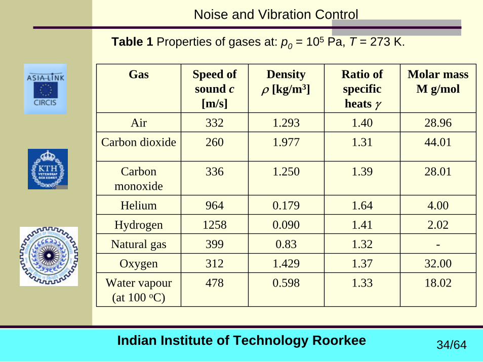
Table 1 Properties of gases at: p0 = 105 Pa, T = 273 K.
Gas Speed of sound c
[m/s]
Densityρ [kg/m3]
Ratio of specific heats γ
Molar massM g/mol
Air 332 1.293 1.40 28.96Carbon dioxide 260 1.977 1.31 44.01
Carbon monoxide
336 1.250 1.39 28.01
Helium 964 0.179 1.64 4.00Hydrogen 1258 0.090 1.41 2.02
Natural gas 399 0.83 1.32 -Oxygen 312 1.429 1.37 32.00
Water vapour (at 100 oC)
478 0.598 1.33 18.02
34/64
Indian Institute of Technology Roorkee
Noise and Vibration Control
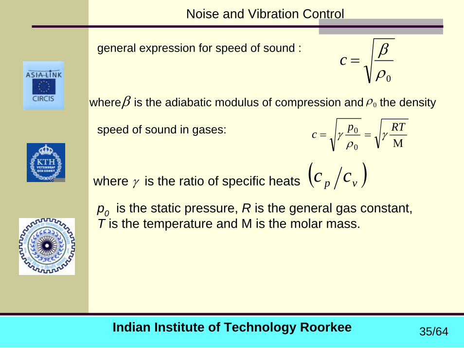
0ρβ
=cgeneral expression for speed of sound :
where is the adiabatic modulus of compression and the density β 0ρ
Μ==
RTpc γ
ργ
0
0speed of sound in gases:
where γ is the ratio of specific heats ( )vp ccp0 is the static pressure, R is the general gas constant, T is the temperature and M is the molar mass.
35/64
Indian Institute of Technology Roorkee
Noise and Vibration Control
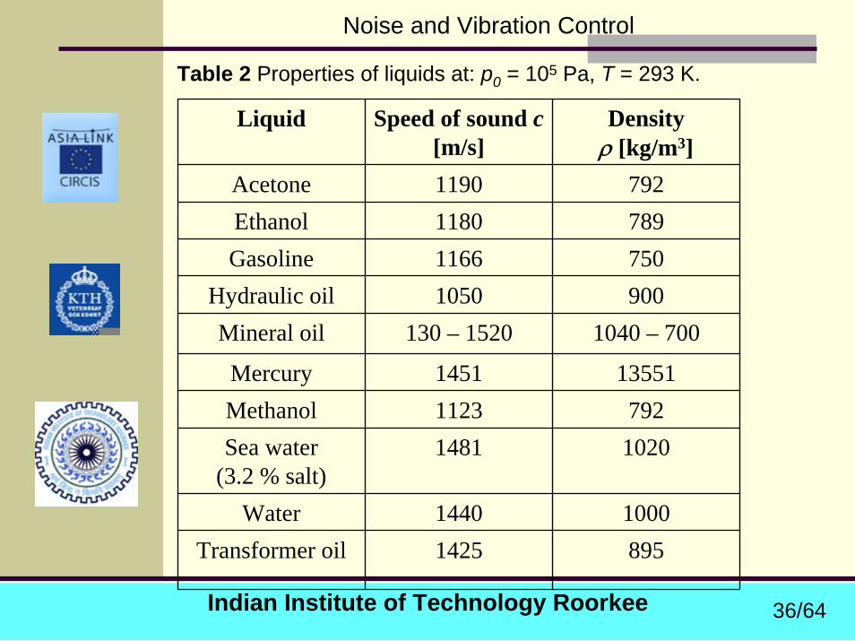
Table 2 Properties of liquids at: p0 = 105 Pa, T = 293 K.
Liquid Speed of sound c[m/s]
Densityρ [kg/m3]
Acetone 1190 792Ethanol 1180 789Gasoline 1166 750
Hydraulic oil 1050 900Mineral oil 130 – 1520 1040 – 700
Mercury 1451 13551Methanol 1123 792Sea water
(3.2 % salt)1481 1020
Water 1440 1000Transformer oil 1425 895
36/64

Indian Institute of Technology Roorkee
Noise and Vibration Control
In liquid filled pipes the speed of sound can be substantially reduced compared to the values given in Table 2.
Effective speed of sound (ce) in a liquid filled pipe for plane wave propagation :
2
2
211
21121
⎟⎟⎠
⎞⎜⎜⎝
⎛−−
⎟⎟⎠
⎞⎜⎜⎝
⎛−+
+
=
o
o
e
dt
dt
E
cc
β
where E is the modulus of elasticity for the pipe material, tis the wall thickness and do is the pipe outer diameter. Above Equation apply only if there are no undissolvedgases in the liquid. If this is the case a substantial reduction of the speed of sound occur.
37/64
Indian Institute of Technology Roorkee
Noise and Vibration Control
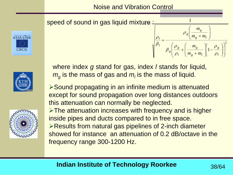
speed of sound in gas liquid mixture :
2
1
1
⎟⎟
⎠
⎞
⎜⎜
⎝
⎛⎟⎟⎠
⎞⎜⎜⎝
⎛−⎟
⎟⎠
⎞⎜⎜⎝
⎛
++
⎟⎟⎠
⎞⎜⎜⎝
⎛
++
=
l
g
lg
g
l
gg
lg
gg
l
l
mmm
mmm
c
ρρ
ρρ
β
ρ
βρ
where index g stand for gas, index l stands for liquid, mg is the mass of gas and ml is the mass of liquid.
Sound propagating in an infinite medium is attenuated except for sound propagation over long distances outdoors this attenuation can normally be neglected.
The attenuation increases with frequency and is higher inside pipes and ducts compared to in free space.
Results from natural gas pipelines of 2-inch diameter showed for instance an attenuation of 0.2 dB/octave in the frequency range 300-1200 Hz.
38/64
Indian Institute of Technology Roorkee
Noise and Vibration Control
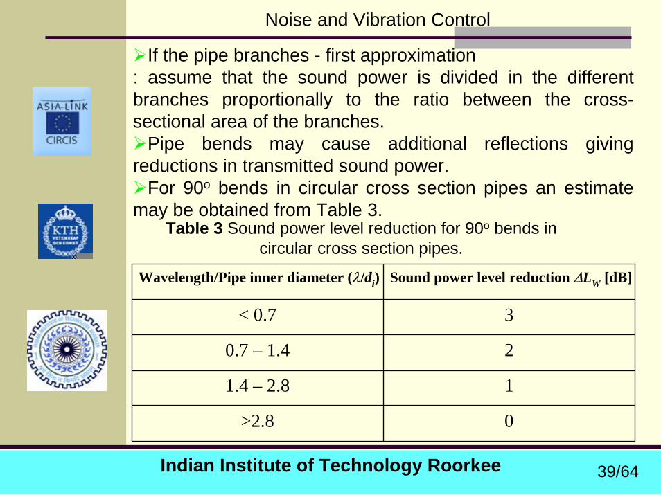
If the pipe branches - first approximation : assume that the sound power is divided in the different branches proportionally to the ratio between the cross-sectional area of the branches.
Pipe bends may cause additional reflections giving reductions in transmitted sound power.
For 90o bends in circular cross section pipes an estimate may be obtained from Table 3.
Table 3 Sound power level reduction for 90o bends in circular cross section pipes.
Wavelength/Pipe inner diameter (λ/di) Sound power level reduction ∆LW [dB]
< 0.7 3
0.7 – 1.4 2
1.4 – 2.8 1
>2.8 0
39/64
Indian Institute of Technology Roorkee
Noise and Vibration Control
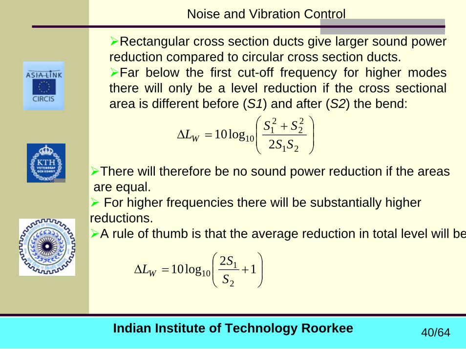
Rectangular cross section ducts give larger sound power reduction compared to circular cross section ducts.
Far below the first cut-off frequency for higher modes there will only be a level reduction if the cross sectional area is different before (S1) and after (S2) the bend:
⎟⎟⎠
⎞⎜⎜⎝
⎛ +=∆
21
22
21
10 2log10
SSSS
LW
There will therefore be no sound power reduction if the areasare equal.
For higher frequencies there will be substantially higherreductions.
A rule of thumb is that the average reduction in total level will be
⎟⎟⎠
⎞⎜⎜⎝
⎛+=∆ 12log10
2
110 S
SLW
40/64
Indian Institute of Technology Roorkee
Noise and Vibration Control
Structure-bone soundPropagation of structure borne sound in pipe walls is more
complicated than propagation of fluid borne sound. A number of different wave types can propagate even though
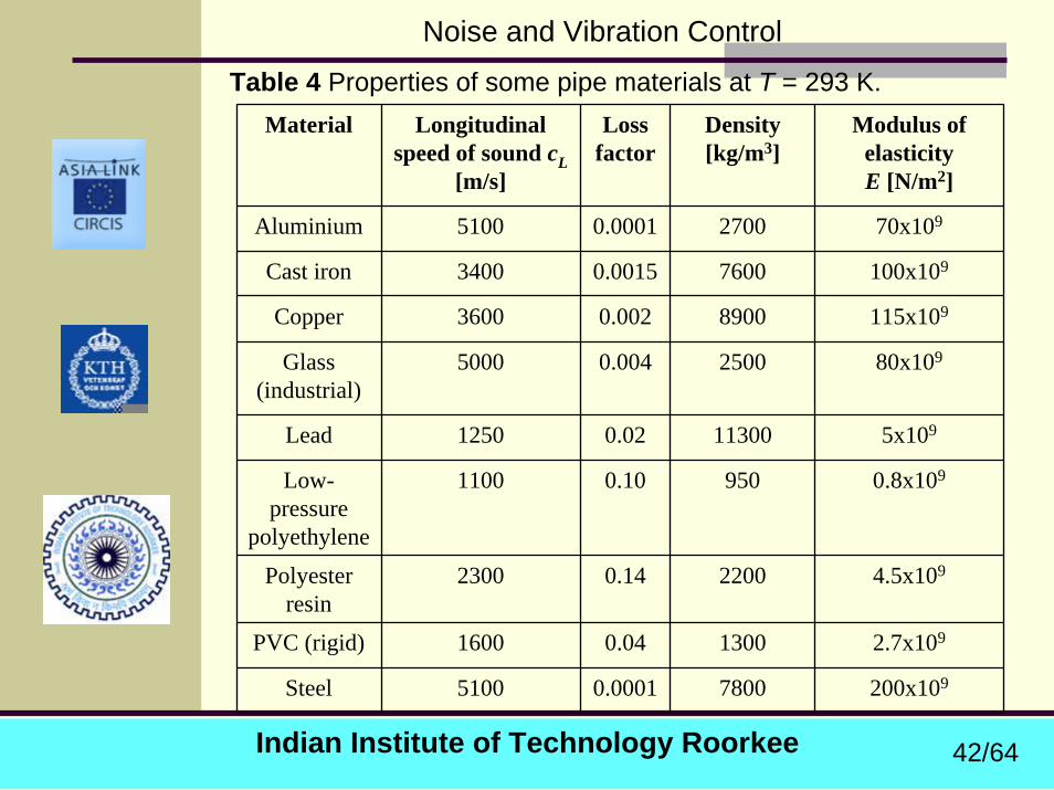
bending waves in the pipe walls normally dominates.Table 4 shows speed of sound, loss factors, surface mass and
modulus of elasticity of some common pipe materials.
For gas filled pipes natural frequencies can be calculated by neglecting interaction between pipe wall vibration and sound propagation in the fluid.
This is not true for liquid filled pipes where interaction has to be taken into account making the problem more complicated.
Natural frequencies determined by the design and location of pipe attachments may be of importance.
As a first approximation the pipe may be treated as a beam attached at discrete points.
41/64
Indian Institute of Technology Roorkee
Noise and Vibration Control
Table 4 Properties of some pipe materials at T = 293 K. Material Longitudinal
speed of sound cL[m/s]
Loss factor
Density [kg/m3]
Modulus of elasticityE [N/m2]
Aluminium 5100 0.0001 2700 70x109
Cast iron 3400 0.0015 7600 100x109
Copper 3600 0.002 8900 115x109
Glass (industrial)
5000 0.004 2500 80x109
Lead 1250 0.02 11300 5x10⁹
Low-pressure
polyethylene
1100 0.10 950 0.8x10⁹
Polyester resin
2300 0.14 2200 4.5x10⁹
PVC (rigid) 1600 0.04 1300 2.7x10⁹
Steel 5100 0.0001 7800 200x109
42/64
Indian Institute of Technology Roorkee
Noise and Vibration Control
Sound Radiation From Pipes
Sound radiation from pipes - from the pipe walls or openings.Pipe wall radiation - excitation comes from:structure borne sound excitation or fluid borne sound excitation. Most results are for gas filled pipes.
Excitation by structure-borne sound
radiation efficiency (s), : a measure of how efficient the structure is as sound radiator compared to a plane piston of the same surface area.
43/64
Indian Institute of Technology Roorkee
Noise and Vibration Control
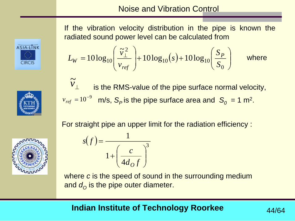
If the vibration velocity distribution in the pipe is known the radiated sound power level can be calculated from
( ) ⎟⎟⎠
⎞⎜⎜⎝
⎛++⎟
⎟⎠
⎞⎜⎜⎝
⎛= ⊥
01010
2
10 log10log10~
log10SSs
vvL P
refW where
⊥v~910−=refv
is the RMS-value of the pipe surface normal velocity,
m/s, SP is the pipe surface area and S0 = 1 m2.
For straight pipe an upper limit for the radiation efficiency :
( ) 3
41
1
⎟⎟⎠
⎞⎜⎜⎝
⎛+
=
fdc
fs
O
where c is the speed of sound in the surrounding medium and dO is the pipe outer diameter.
44/64
Indian Institute of Technology Roorkee
Noise and Vibration Control
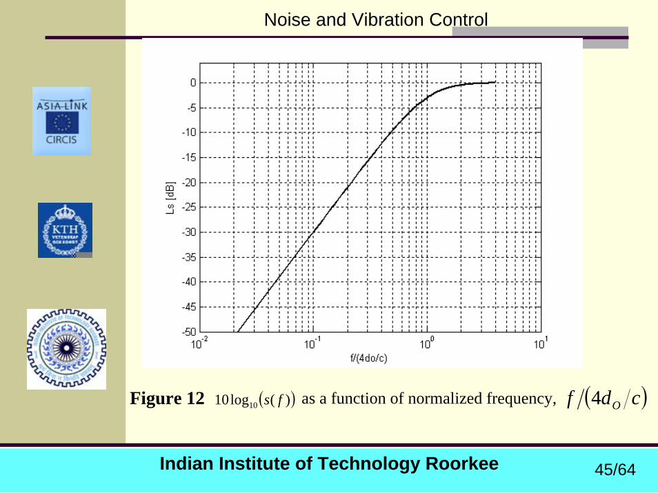
( ))(log10 10 fs ( )cdf O4Figure 12 as a function of normalized frequency,
45/64
Indian Institute of Technology Roorkee
Noise and Vibration Control
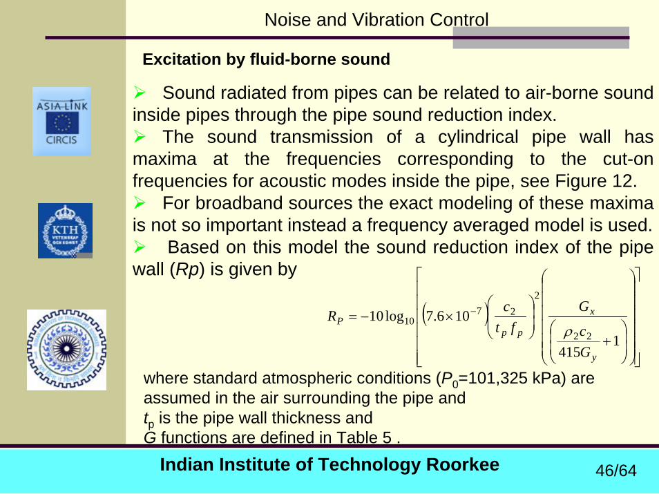
Excitation by fluid-borne sound
Sound radiated from pipes can be related to air-borne sound inside pipes through the pipe sound reduction index.
The sound transmission of a cylindrical pipe wall has maxima at the frequencies corresponding to the cut-on frequencies for acoustic modes inside the pipe, see Figure 12.
For broadband sources the exact modeling of these maxima is not so important instead a frequency averaged model is used.
Based on this model the sound reduction index of the pipe wall (Rp) is given by
( )
⎥⎥⎥⎥⎥⎥
⎦
⎤
⎢⎢⎢⎢⎢⎢
⎣
⎡
⎟⎟⎟⎟⎟⎟
⎠
⎞
⎜⎜⎜⎜⎜⎜
⎝
⎛
⎟⎟⎠
⎞⎜⎜⎝
⎛+
⎟⎟⎠
⎞⎜⎜⎝
⎛×−= −
1415
106.7log1022
227
10
y
x
ppP
Gc
Gft
cR
ρ
where standard atmospheric conditions (P0=101,325 kPa) are assumed in the air surrounding the pipe and tp is the pipe wall thickness and G functions are defined in Table 5 .
46/64
Indian Institute of Technology Roorkee
Noise and Vibration Control
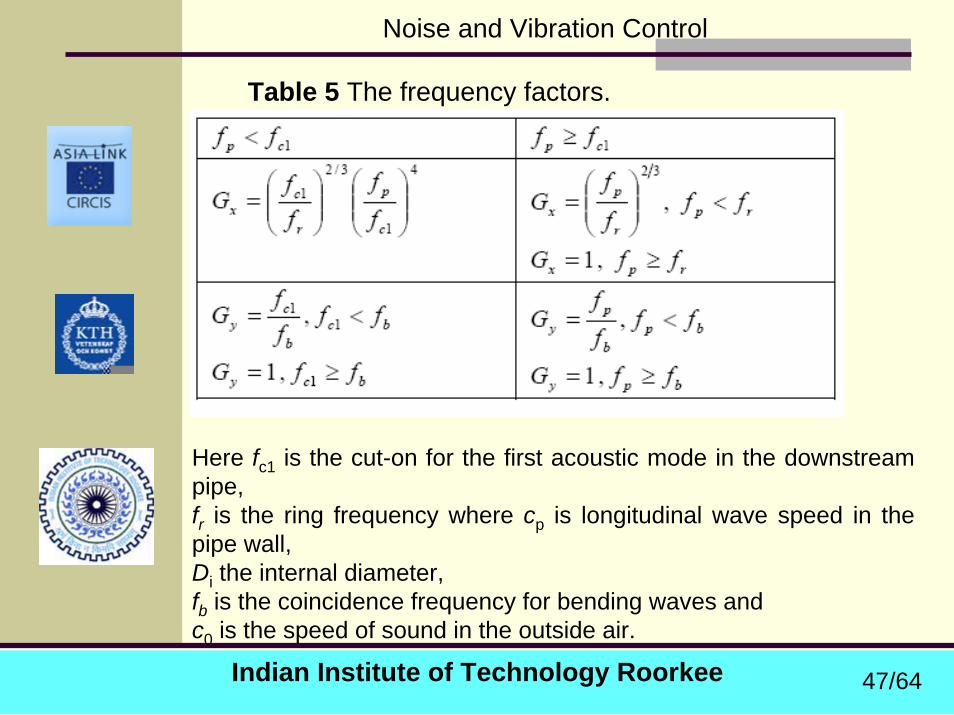
Table 5 The frequency factors.
Here fc1 is the cut-on for the first acoustic mode in the downstream pipe,fr is the ring frequency where cp is longitudinal wave speed in the pipe wall, Di the internal diameter,fb is the coincidence frequency for bending waves and c0 is the speed of sound in the outside air.
47/64
Indian Institute of Technology Roorkee
Noise and Vibration Control
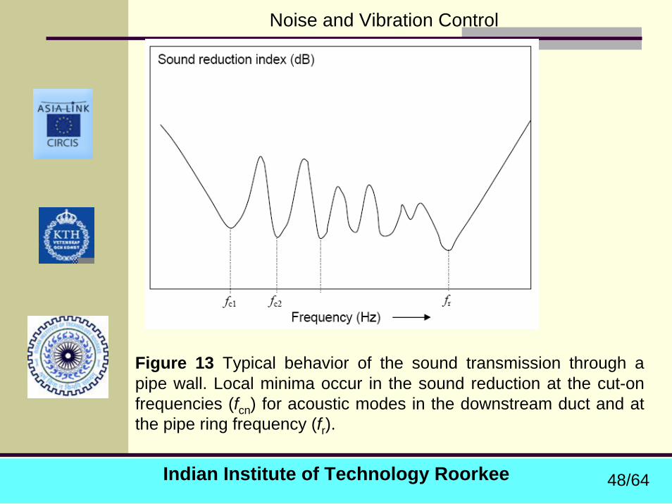
Figure 13 Typical behavior of the sound transmission through a pipe wall. Local minima occur in the sound reduction at the cut-on frequencies (fcn) for acoustic modes in the downstream duct and at the pipe ring frequency (fr).
48/64
Indian Institute of Technology Roorkee
Noise and Vibration Control
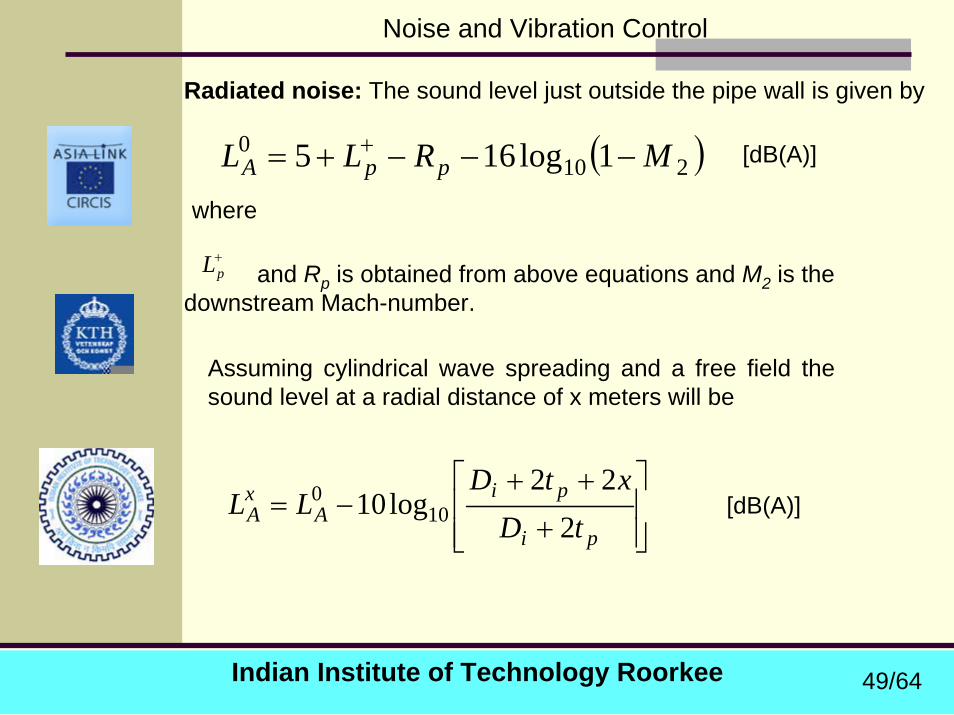
Radiated noise: The sound level just outside the pipe wall is given by
( )2100 1log165 MRLL ppA −−−+= +
where
[dB(A)]
+pL and Rp is obtained from above equations and M2 is the
downstream Mach-number.
Assuming cylindrical wave spreading and a free field the sound level at a radial distance of x meters will be
⎥⎥⎦
⎤
⎢⎢⎣
⎡
+
++−=
pi
piA
xA tD
xtDLL
222
log10 100 [dB(A)]
49/64
Indian Institute of Technology Roorkee
Noise and Vibration Control
7.4 Noise Control TechniquesNoise control can be applied :
at the source (Preferable)during the propagation path at the receiver.
Noise control at the source
Fans, pumps and compressors are major noise sources in pipes. (Already discussed in Chapter 5)
Therefore only control of noise associated with the flow in pipe discussed here.
Setting the flow rate as low as possible for the application in question is therefore an important noise control technique.
Noise created by a high speed ( > 40 m/s for gases) turbulent flow in a pipe must be considered.
50/64
Indian Institute of Technology Roorkee
Noise and Vibration Control
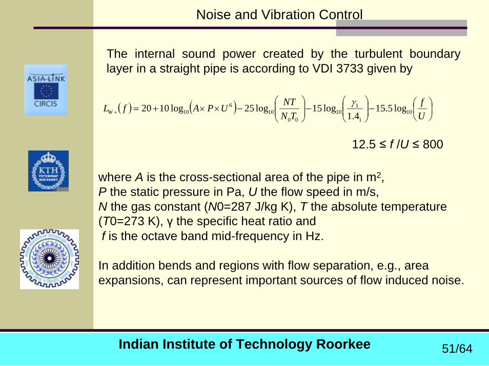
The internal sound power created by the turbulent boundary layer in a straight pipe is according to VDI 3733 given by
( ) ( ) ⎟⎠⎞
⎜⎝⎛−⎟⎟
⎠
⎞⎜⎜⎝
⎛−⎟⎟
⎠
⎞⎜⎜⎝
⎛−××+=+ U
fTN
NTUPAfLW 101
110
0010
610 log5.15
4.1log15log25log1020 γ
12.5 ≤ f /U ≤ 800
where A is the cross-sectional area of the pipe in m2, P the static pressure in Pa, U the flow speed in m/s, N the gas constant (N0=287 J/kg K), T the absolute temperature (T0=273 K), γ the specific heat ratio andf is the octave band mid-frequency in Hz.
In addition bends and regions with flow separation, e.g., area expansions, can represent important sources of flow induced noise.
51/64
Indian Institute of Technology Roorkee
Noise and Vibration Control
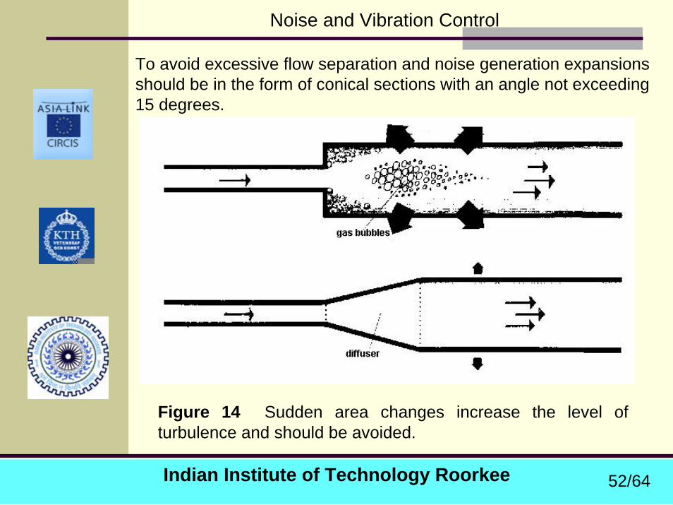
To avoid excessive flow separation and noise generation expansions should be in the form of conical sections with an angle not exceeding 15 degrees.
Figure 14 Sudden area changes increase the level of turbulence and should be avoided.
52/64
Indian Institute of Technology Roorkee
Noise and Vibration Control
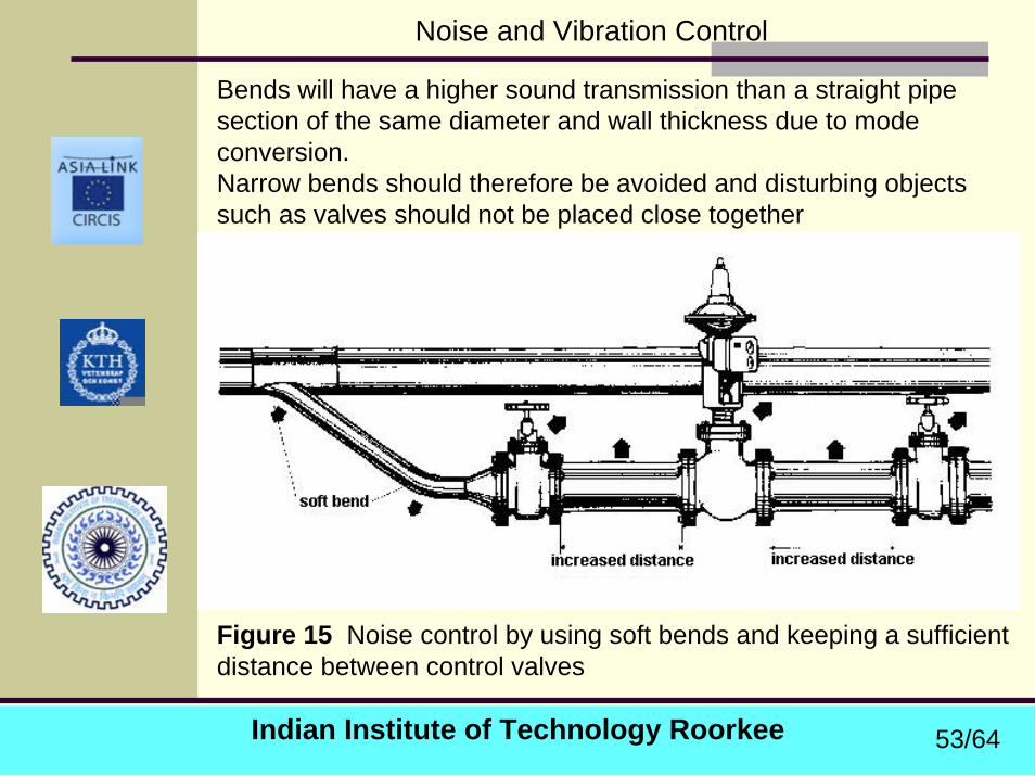
Bends will have a higher sound transmission than a straight pipesection of the same diameter and wall thickness due to mode conversion. Narrow bends should therefore be avoided and disturbing objects such as valves should not be placed close together
Figure 15 Noise control by using soft bends and keeping a sufficient distance between control valves
53/64
Indian Institute of Technology Roorkee
Noise and Vibration Control
Steady state noise associated with control valves :
A control valve converts pressure energy into heat in order to control the mass flow.
The heat conversion normally takes place via turbulent flow losses with associated noise generation.
It is possible to design control valves where the heat production is created via laminar flow losses, which would result in a virtually noise free operation.
However, Standard valve designs are based on turbulent dissipation and for such valves the generated noise is proportional to the pressure drop ΔP .
54/64

Indian Institute of Technology Roorkee
Noise and Vibration Control
Based on a study of orifice plates the acoustic power scales as
4.2iAPW β∆∝
where Ai is the outlet jet area. The value of the exponent β is 4 for the subsonic case and 3 for a choked flow. Equation suggests two methods for reducing the source strength. (i) single flow path multistage valve trims- where a desired pressure drop is split into a number of steps. Assuming an unchanged jet area and N equal steps that act as independent sources, the total power compared to the single step arrangement is
β−= 1NWWN
55/64
Indian Institute of Technology Roorkee
Noise and Vibration Control
(ii) The second alternative is so called single stage multiple flow path valve trims where the outlet jet is split into a number of smaller interacting jets.
This procedure will lead to a decrease in the power which, assuming N independent paths (sources), will be proportional N1.4 .
Another effect of decreasing the jet size is that the peak frequency of the spectrum will be shifted upwards.
This has a positive effect due to the reduced sensitivity of the human ear at higher frequencies.
It is also possible to combine both alternatives and design multipath, mulitistage valve trims.
56/64
Indian Institute of Technology Roorkee
Noise and Vibration Control
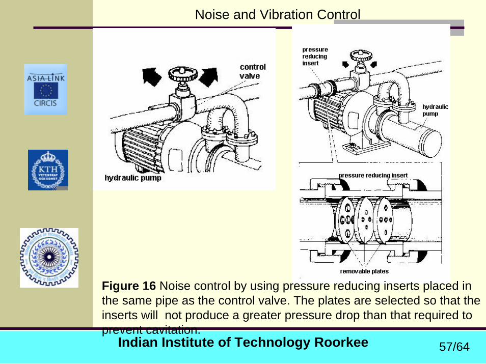
Figure 16 Noise control by using pressure reducing inserts placed in the same pipe as the control valve. The plates are selected so that the inserts will not produce a greater pressure drop than that required to prevent cavitation.
57/64
Indian Institute of Technology Roorkee
Noise and Vibration Control
Noise control during the propagation path
In gas filled systems silencers can be used to reduce noise. There are two basic types of silencers reflective and dissipative.Reflective silencers create a reflection of waves by an impedance mismatch, e.g., by an area change or a side-branch resonator. The reflective silencer type is primarily intended for the plane wave range and is efficient for stopping single tones. Dissipative silencers are based on dissipation of acoustic energy into heat via porous materials such as fiberglass or steel wool. These silencers are best suited for broad-band sources and for the mid- or high frequency range. Different types of silencers have already been discussed.
58/64
Indian Institute of Technology Roorkee
Noise and Vibration Control
Transmission of structure borne sound to pipes from surrounding structures or vice versa should be avoided by flexible couplings at the pipe clamping points.
These can be rubber inserts or different types of springs.
Pipes should furthermore be secured to structures at points with high input impedance.
If the main propagation takes place in the pipe wall blocking masses can be used.
In the case of liquid filled pipes this may not be a good solution because the pulsation in the liquid may excite the pipe wall immediately after such a structure-borne sound barrier.
59/64
Indian Institute of Technology Roorkee
Noise and Vibration Control
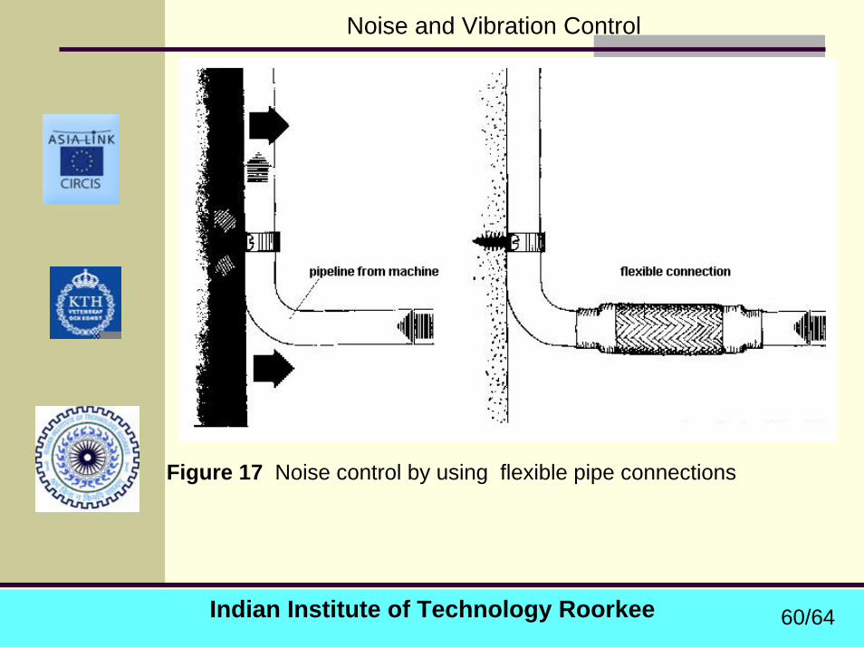
Figure 17 Noise control by using flexible pipe connections
60/64
Indian Institute of Technology Roorkee
Noise and Vibration Control
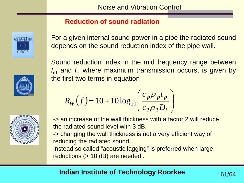
Reduction of sound radiation
For a given internal sound power in a pipe the radiated sound depends on the sound reduction index of the pipe wall.
Sound reduction index in the mid frequency range between fc1 and fr, where maximum transmission occurs, is given by the first two terms in equation
( ) ⎟⎟⎠
⎞⎜⎜⎝
⎛+=
i
pppW Dc
tcfR
2210log1010
ρρ
-> an increase of the wall thickness with a factor 2 will reduce the radiated sound level with 3 dB. -> changing the wall thickness is not a very efficient way of reducing the radiated sound.Instead so called “acoustic lagging” is preferred when large reductions (> 10 dB) are needed .
61/64

Indian Institute of Technology Roorkee
Noise and Vibration Control
Similar to a vibration isolation and aims at shielding the original pipe with a structure that has a reduced vibration level.
This is done by wrapping the pipe with a porous material and covering this with a limp and impervious top sheet.
The porous material provides together with the enclosed air stiffness and damping.
The damping is important to reduce the effect of acoustic modes between the pipe wall and the top sheet.
Assuming that the top sheet is mass-controlled the increase in sound reduction index for frequencies well above the fundamental mass-spring resonance will be
2
0010 2
log10 ⎟⎟⎠
⎞⎜⎜⎝
⎛ ′′=∆
ρωcm
R p
where ω is the angular frequency, m′′ is the mass per m2 of the top sheet, ρ0 is the density of air and c0 the speed of sound in air.
62/64
Indian Institute of Technology Roorkee
Noise and Vibration Control
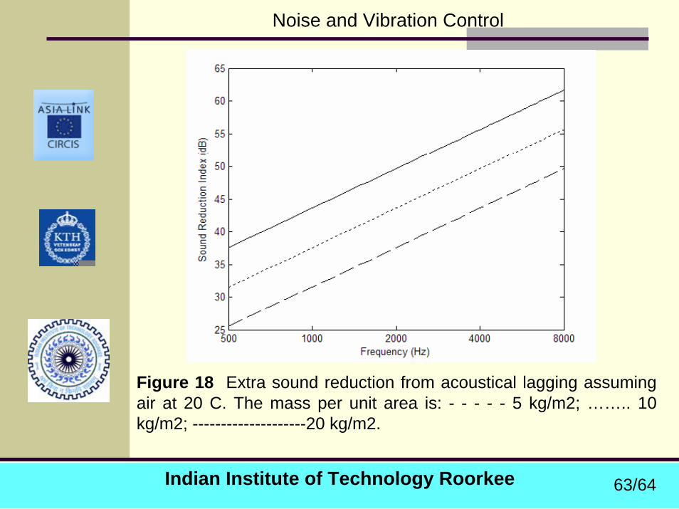
Figure 18 Extra sound reduction from acoustical lagging assuming air at 20 C. The mass per unit area is: - - - - - 5 kg/m2; …….. 10 kg/m2; --------------------20 kg/m2.
63/64
Indian Institute of Technology Roorkee
Noise and Vibration Control
Thank youThank you
64/64