no job name · the nissan green program symbol indicates environmentally friendly information and...
TRANSCRIPT

NV200OWNER’S MANUAL

ForewordWelcome to the growing family of new NISSAN owners. This vehicle has been delivered to you with confidence. It has been produced using the latest techniquesand strict quality control.
This manual was prepared to help you understand the operation and maintenance of your vehicle so that you may enjoy many kilometres (miles) of driving pleasure.Please read through this manual before operating your vehicle.
A separate Warranty Information & Maintenance Booklet explains in detail the warranty coverage that applies to your vehicle.
Your NISSAN dealer knows your vehicle best. When you require any service or have any questions, your NISSAN dealer will be glad to assist you with the extensiveresources available for you.
IMPORTANT SAFETY INFORMATION
REMINDERS FOR SAFETY!Follow these important driving rules to help ensure a safe and complete trip foryou and your passengers!
• NEVER drive under the influence of alcohol or drugs.
• ALWAYS observe posted speed limits and never drive too fast for condi-tions.
• ALWAYS use your seat belts and appropriate child restraint systems.Preteen children should be seated in the rear seat.
• ALWAYS provide information about the proper use of vehicle safety fea-tures to all occupants of the vehicle.
• ALWAYS review this Owner’s Manual for important safety information.
WHEN READING THE MANUALThis manual includes information for all options available on this model. There-fore, you may find some information that does not apply to your vehicle.
All information, specifications and illustrations in this manual are those in effectat the time of printing. NISSAN reserves the right to change specifications ordesigns at any time without notice and without obligation.
MODIFICATION OF YOUR VEHICLEThis vehicle should not be modified. Modifications could affect its performance,safety or durability, and may even violate governmental regulations. In addition,damage or performance problems resulting from modifications may not be cov-ered under NISSAN warranties.
READ FIRST — THEN DRIVE SAFELYBefore driving your vehicle, read this Owner’s Manual carefully. This will ensurefamiliarity with controls and maintenance requirements, assisting you in the safeoperation of your vehicle.
Throughout this manual the following symbols and words are used:
WARNING
Indicates the presence of a hazard that could cause death or serious per-sonal injury. To avoid or reduce the risk, the procedures described must befollowed precisely.
CAUTION
Indicates the presence of a hazard that could cause minor or moderate per-sonal injury, or damage to your vehicle. To avoid or reduce the risk, the pro-cedures described must be followed carefully.
NOTE
Indicates additional helpful information.

The NISSAN GREEN PROGRAM symbol indicates environmentally friendlyinformation and best practices.
This symbol means “Do not do this” or “Do not let this happen”.
Arrows in an illustration that are similar to these point to the front of the vehicle.
Arrows in an illustration that are similar to these indicate movement or action.
Arrows in an illustration that are similar to these call attention to an item in theillustration.
BATTERY DISPOSALCAUTION
An improperly disposed battery can harm the environment. Always confirmlocal regulations for battery disposal.
Examples of the batteries that the vehicle contains:
• Vehicle battery
• Remote controller battery (for Intelligent Key and/or Remote keyless entrysystem)
• Tyre Pressure Monitoring System (TPMS) sensor battery
• Remote controller battery (for Mobile Entertainment system)
If in doubt, contact your local authority, or a NISSAN dealer, or a qualified work-shop for advice on disposal.


Contents Illustrated table of contents 0
Safety — seats, seat belts and supplementalrestraint system 1
Instruments and controls 2
Pre-driving checks and adjustments 3
Display screen, heater and air conditioner, andaudio system 4
Starting and driving 5
In case of emergency 6
Appearance and care 7
Maintenance and do-it-yourself 8
Technical information 9
Index 10


0 Illustrated table of contentsIllustrated table of contents
Seats, seat belts and Supplemental RestraintSystem (SRS).......................................................... 0-2Exterior front ............................................................ 0-3Exterior rear............................................................. 0-4Passenger compartment .......................................... 0-5Cockpit ................................................................... 0-6
Left-hand drive (LHD) model............................... 0-6Right-hand drive (RHD) model ............................ 0-7
Instrument panel ...................................................... 0-8Left-hand drive (LHD) model............................... 0-8Right-hand drive (RHD) model ............................ 0-9
Meters and gauges .................................................. 0-10Engine compartment................................................ 0-11
HR16DE engine model ....................................... 0-11K9K engine model .............................................. 0-12

1. Supplemental front-impact air bags* (Page1-21)
2. Supplemental side-impact air bags* (P. 1-21)
3. Seat belts (P. 1-7)
4. Head restraints (P. 1-6)
5. ISOFIX child restraint system* (P. 1-11)
6. Second row centre seat belt* (P. 1-10)
7. Front seats (P. 1-2)
8. Pre-tensioner seat belt system (P. 1-23)
9. Second row seats* (P. 1-3)— Child restraints (P. 1-11)
10. Child restraint anchor points (for top tetherstrap child restraint)* (P. 1-15)
11. Third row seats* (P. 1-5)
*: where fitted
SSI0596
SEATS, SEAT BELTS AND SUPPLEMENTAL RESTRAINT SYSTEM (SRS)
0-2 Illustrated table of contents

1. Engine bonnet (P. 3-19)
2. Windscreen wiper and washer— Switch operation (P. 2-22)— Blade replacement (P. 8-15)— Window washer fluid (P. 8-16)
3. Antenna (P. 4-9)
4. Headlights and turn signal lights
— Switch operation (P. 2-17)— Bulb replacement (P. 8-21, P. 8-22)
5. Windows (P. 2-25)
6. Recovery hook (P. 6-9)
7. Fog lights*— Switch operation (P. 2-21)— Bulb replacement (P. 8-22)
8. Tyres— Tyres and wheels (P. 8-26, P. 9-6)— Flat tyre (P. 6-2)— Tyre placard (P. 9-8)
9. Side turn signal light— Switch operation (P. 2-21)— Bulb replacement (P. 8-22)
10. Outside mirrors (P. 3-23)
11. Doors— Keys (P. 3-2)— Door locks (P. 3-4)— Intelligent Key system* (P. 3-10)— Remote keyless entry system* (P. 3-8)
12. Child safety sliding door lock* (P. 3-8)
*: where fitted
SSI0597
EXTERIOR FRONT
Illustrated table of contents 0-3

1. Rear window wiper and washer*— Switch operation (P. 2-23)— Window washer fluid (P. 8-16)
2. High-mounted stop light— Bulb replacement (P. 8-22)
3. Rear window defogger (P. 2-24)
4. Sliding windows* (P. 2-25)
5. Sliding door(s) (P. 3-6)
6. Fog light (LHD model) or Reverse light (RHDmodel)— Fog light switch operation (P. 2-21)— Bulb replacement (P. 8-22)
7. Rear view camera* (P. 4-2)
8. Back door (P. 3-20)
— Intelligent Key system* (P. 3-10)— Remote keyless entry system* (P. 3-8)
9. Number plate lights— Bulb replacement (P. 8-22)
10. Recovery hook (P. 6-9)
11. Stop/tail lights— Bulb replacement (P. 8-22)
12. Reverse light (LHD model) or Fog light (RHDmodel)— Fog light switch operation (P. 2-21)— Bulb replacement (P. 8-22)
13. Turn signal lights— Switch operation (P. 2-21)— Bulb replacement (P. 8-22)
14. Fuel filler lid— Opener operation (P. 3-22)— Fuel recommendation (P. 9-4)
*: where fitted
jA Tailgate model
jB French door modelSSI0744
EXTERIOR REAR
0-4 Illustrated table of contents

1. Inside rearview mirror* (P. 3-23)
2. Sun visors (P. 2-33)— Ticket holders (P. 2-31)
3. Door armrest— Power window switch* (P. 2-25)
4. Room lights (P. 2-34)
5. Room lights* (P. 2-34)
6. Bottle holders* (P. 2-29)
7. Sliding windows* (P. 2-25)
8. Third row seat cup holders* (P. 2-30)
9. Luggage compartment light (P. 2-34)
10. Console box (P. 2-29)
11. Rear cup holders (P. 2-29)
12. Second row seat power outlet* (P. 2-27)
13. Rear cooler fan switch* (P. 4-7)
14. Luggage room— Storage (P. 2-28)— Luggage hooks (P. 2-32)— Tonneau cover* (P. 2-32)
*: where fitted
NIC1625
PASSENGER COMPARTMENT
Illustrated table of contents 0-5

LEFT-HAND DRIVE (LHD) MODEL1. Front cup holder (P. 2-29)
2. Side vent (P. 4-4)
3. Headlight, fog light and turn signal switch(P. 2-17)
4. Meters and gauges (P. 2-2)
5. Wiper and washer switch (P. 2-22)
6. Fuel filler lid opener handle (P. 3-22)
7. Bonnet release handle (P. 3-19)
8. Card holder (P. 2-31)/Fuse box cover(P. 8-21)
9. Headlight aiming control switch (P. 2-18)
10. Outside rearview mirror remote control switch*(P. 3-23)
11. Steering wheel— Electric power steering system (P. 5-14)— Horn (P. 2-25)— Driver supplemental air bag (P. 1-21)
12 Ignition switch/steering lock (P. 5-4)
13. Shift lever for Manual Transmission (MT)model (P. 5-8)
14. Parking brake (P. 3-24, P. 5-11)
*: where fitted
SSI0622
COCKPIT
0-6 Illustrated table of contents

RIGHT-HAND DRIVE (RHD) MODEL1. Headlight, fog light and turn signal switch
(P. 2-17)
2. Meters and gauges (P. 2-2)
3. Wiper and washer switch (P. 2-22)
4. Outside rearview mirror remote control switch*(P. 3-23)
5. Headlight aiming control switch (P. 2-18)
6. Side vent (P. 4-4)
7. Front cup holder (P. 2-29)
8. Parking brake (P. 3-24, P. 5-11)
9. Shift lever for Manual Transmission (MT)model (P. 5-8)
10. Steering wheel— Electric power steering system (P. 5-14)— Horn (P. 2-25)— Driver supplemental air bag (P. 1-21)
11. Ignition switch/steering lock (P. 5-4)
12. Bonnet release handle (P. 3-19)
13. Fuel filler lid opener handle (P. 3-22)
14. Card holder (P. 2-31)/Fuse box cover(P. 8-21)
*: where fitted
SSI0601
Illustrated table of contents 0-7
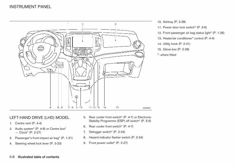
LEFT-HAND DRIVE (LHD) MODEL1. Centre vent (P. 4-4)
2. Audio system* (P. 4-8) or Centre box*— Clock* (P. 2-27)
3. Passenger’s front-impact air bag* (P. 1-21)
4. Steering wheel lock lever (P. 3-23)
5. Rear cooler front switch* (P. 4-7) or ElectronicStability Programme (ESP) off switch* (P. 5-9)
6. Rear cooler front switch* (P. 4-7)
7. Defogger switch* (P. 2-24)
8. Hazard indicator flasher switch (P. 2-24)
9. Front power outlet* (P. 2-27)
10. Ashtray (P. 2-28)
11. Power door lock switch* (P. 3-6)
12. Front passenger air bag status light* (P. 1-26)
13. Heater/air conditioner* control (P. 4-4)
14. Utility hook (P. 2-31)
15. Glove box (P. 2-28)
*: where fitted
SSI0603
INSTRUMENT PANEL
0-8 Illustrated table of contents

RIGHT-HAND DRIVE (RHD) MODEL1. Passenger’s front-impact air bag* (P. 1-21)
2. Centre vent (P. 4-4)
3. Audio system* (P. 4-8) or Centre box*— Clock* (P. 2-27)
4. Glove box (P. 2-28)
5. Utility hook (P. 2-31)
6. Heater/air conditioner* control (P. 4-4)
7. Defogger switch* (P. 2-24)
8. Front passenger air bag status light* (P. 1-26)
9. Power door lock switch (P. 3-6)
10. Front power outlet* (P. 2-27)
11. Ashtray (P. 2-28)
12. Hazard indicator flasher switch (P. 2-24)
13. Rear cooler front switch* (P. 4-7)
14. Rear cooler front switch* (P. 4-7) or ElectronicStability Programme (ESP) off switch* (P. 5-9)
15. Steering wheel lock lever (P. 3-23)
*: where fitted
SSI0602
Illustrated table of contents 0-9

1. Speedometer (P. 2-2)
2. Vehicle information display (P. 2-4)— Rear view monitor* (P. 4-2)— Tachometer (P. 2-7)— Trip computer (P. 2-6)— Indicators, warnings and alerts (P. 2-4)— Engine oil information (P. 2-9)
3. Clock (P. 2-27)
4. Fuel gauge (P. 2-2)
5. Warning/indicator lights (P. 2-10)
6. Instrument brightness control switch (P. 2-3)/Trip computer mode switch (P. 2-6)
7. Trip odometer reset switch (P. 2-2)
8. Upshift indicator (P. 2-5, P. 5-9)
9. Trip odometer (P. 2-2)
10. Odometer (P. 2-2)
*: where fitted
SSI0604
METERS AND GAUGES
0-10 Illustrated table of contents
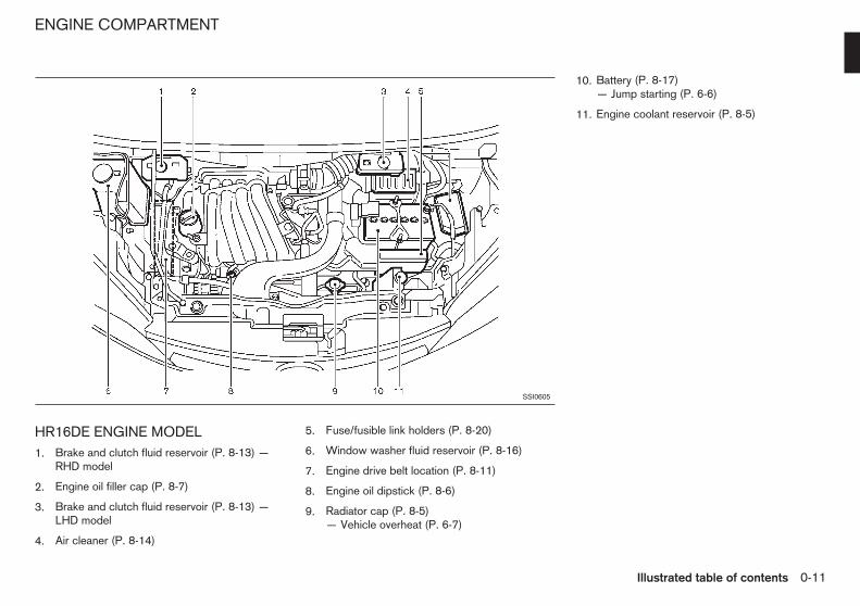
HR16DE ENGINE MODEL1. Brake and clutch fluid reservoir (P. 8-13) —
RHD model
2. Engine oil filler cap (P. 8-7)
3. Brake and clutch fluid reservoir (P. 8-13) —LHD model
4. Air cleaner (P. 8-14)
5. Fuse/fusible link holders (P. 8-20)
6. Window washer fluid reservoir (P. 8-16)
7. Engine drive belt location (P. 8-11)
8. Engine oil dipstick (P. 8-6)
9. Radiator cap (P. 8-5)— Vehicle overheat (P. 6-7)
10. Battery (P. 8-17)— Jump starting (P. 6-6)
11. Engine coolant reservoir (P. 8-5)
SSI0605
ENGINE COMPARTMENT
Illustrated table of contents 0-11

K9K ENGINE MODEL1. Window washer fluid reservoir (P. 8-16)
2. Brake and clutch fluid reservoir (P. 8-13) —RHD model
3. Engine oil filler cap (P. 8-7)
4. Brake and clutch fluid reservoir (P. 8-13) —LHD model
5. Air cleaner (P. 8-14)
6. Battery (P. 8-17)
7. Engine drive belt location (P. 8-11)
8. Engine oil dipstick (P. 8-6)
9. Engine coolant reservoir (P. 8-5)
10. Fuse/Fusible link holders (P. 8-20)
SSI0609
0-12 Illustrated table of contents
1 Safety — seats, seat belts and supplementalrestraint systemSafety — seats, seat belts and supplementalrestraint system
Seats....................................................................... 1-2Front seats ......................................................... 1-2Second row seats (where fitted) ......................... 1-3Third row seats (where fitted) ............................. 1-5Head restraints ................................................... 1-6
Seat belts ................................................................ 1-7Precautions on seat belt usage ........................... 1-7Child safety ........................................................ 1-8Pregnant women ................................................ 1-8Injured persons................................................... 1-9Centre mark on seat belts (where fitted) ............. 1-9Three-point type seat belts.................................. 1-9
Child restraints ........................................................ 1-11Precautions on child restraint usage.................... 1-11
Universal child restraints for front seat and rearseats .................................................................. 1-12ISOFIX child restraint system (where fitted) ........ 1-14Child restraint anchorage (where fitted) .............. 1-15Child restraint installation using ISOFIX .............. 1-16Child restraint installation using 3-point typeseat belt ............................................................. 1-18
Supplemental Restraint System (SRS) ..................... 1-21Precautions on Supplemental RestraintSystem (SRS)..................................................... 1-21Supplemental air bag systems ............................ 1-25Pre-tensioner seat belt system (where fitted) ....... 1-27Repair and replacement procedure ..................... 1-27

WARNING
• Do not drive and/or ride in the vehicle withthe seatback reclined. This can be danger-ous. The shoulder belt will not be properlyagainst the body. In an accident, you and yourpassengers could be thrown into the shoul-der belt and receive neck or other seriousinjuries. You and your passengers could alsoslide under the lap belt and receive seriousinjuries.
• For the most effective protection while thevehicle is in motion, the seatback should beupright. Always sit well back in the seat andadjust the seat belt properly. (See “Seat belts”later in this section.)
CAUTION
When adjusting the seat positions, be sure not tocontact any moving parts to avoid possible inju-ries and/or damages.
FRONT SEATS
WARNING
Do not adjust the driver’s seat while driving sothat full attention may be given to vehicle opera-tion.
Manual seat adjustment
WARNING
After adjusting a seat, gently shake the seat toconfirm that the seat is locked securely. If theseat is not locked securely, it may move sud-denly and could cause the loss of control of thevehicle.
SSS0133AZ
SEATS
1-2 Safety — seats, seat belts and supplemental restraint system
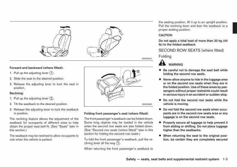
Forward and backward (where fitted):
1. Pull up the adjusting lever j1 .
2. Slide the seat to the desired position.
3. Release the adjusting lever to lock the seat inposition.
Reclining:
1. Pull up the adjusting lever j2 .
2. Tilt the seatback to the desired position.
3. Release the adjusting lever to lock the seatbackin position.
The reclining feature allows the adjustment of theseatback for occupants of different sizes to helpobtain the proper seat belt fit. (See “Seats” later inthis section.)
The seatback may be reclined to allow occupants torest when the vehicle is parked.
Folding front passenger’s seat (where fitted):
The front passenger’s seatback can be folded down.Some long objects may be loaded in the vehiclewhen the second row seats are also folded down.(See “Second row seats (where fitted)” later in thissection for folding the second row seats.)
To fold the front passenger’s seatback, pull the re-clining lever all the way j1 .
When returning the front passenger’s seatback to
the seating position, lift it up to an upright position.Pull the reclining lever and lean the seatback to aproper seating position.
CAUTION
Do not apply a total load of more than 20 kg (44lb) to the folded seatback.
SECOND ROW SEATS (where fitted)
Folding
WARNING
• Be careful not to damage the seat belt whilefolding the second row seats.
• Never allow anyone to ride in the luggage areaor on the second row seats when they are inthe folded position. Use of these areas by pas-sengers without proper restraints could resultin serious injury in an accident or sudden stop.
• Do not fold the second row seats while thevehicle is moving.
• Do not fold the second row seats when occu-pants are in the second row seats area or anyluggage is on the second row seats.
• Properly secure all luggage to help prevent itfrom sliding or shifting. Do not place luggagehigher than the seatbacks.
• When returning the seat to the original posi-tion, be certain they are completely secured
SSS0955Z
SSS0956Z
Safety — seats, seat belts and supplemental restraint system 1-3

in the latched position. If they are not com-pletely secured, passengers may be injured inan accident or sudden stop.
• Securely store the removed head restraints toprevent them from being thrown around incase of a sudden stop or accident.
• Head restraints should be adjusted properlyas they may provide significant protectionagainst whiplash injury. Always replace andadjust them properly if they have been re-moved for any reason.
1. Move the head restraint to its lowest position.
2. Pull the strap j1 and fold the seatback down j2 .
3. Pull the lock strap j3 , and then lift the seat cush-ion and fold it forward j4 .
4. Fold the seat leg j5 downward.
5. Hang the hook j6 (stored in the back side of theseat cushion) on the head restraint stalk of thefront seat.
6. Adjust the strap if necessary. Pull the adjuster upto loosen j7 or pull the strap out to tighten j8 .
CAUTION
Do not fold the second row seats when the thirdrow seats are occupied while the vehicle is inmotion.
SSS1112
1-4 Safety — seats, seat belts and supplemental restraint system

Returning:
1. Pull the adjuster j1 up to loosen.
2. Remove the hook j2 and store it in the pocketon the backside of the seat.
3. Unfold the seat leg j3 and pull the strap j4 toreturn the seat in position.
4. Pull the strap j5 and unfold the seatback j6until it is latched.
THIRD ROW SEATS (where fitted)
FoldingCAUTION
Do not use the third row seats with the secondrow seats folded while the vehicle is in motion.
WARNING
• Be careful not to damage the seat belt whilefolding the third row seats.
• Never allow anyone to ride in the luggage areaor on the third row seats when they are in thefold-down position. Use of these areas by pas-sengers without proper restraints could resultin serious injury in an accident or sudden stop.
• Do not fold the third row seats while the ve-hicle is moving.
• Do not fold down the third row seatback whenoccupants are in the third row seat area orany luggage is on the third row seats.
• Properly secure all luggage to help prevent itfrom sliding or shifting. Do not place luggagehigher than the seatbacks.
• When returning the seatbacks to the uprightposition, be certain they are completely se-cured in the latched position. If they are notcompletely secured, passengers may be in-jured in an accident or sudden stop.
• Securely store the removed head restraints toprevent them from being thrown around incase of a sudden stop or accident.
• Head restraints should be adjusted properlyas they may provide significant protectionagainst whiplash injury. Always replace andadjust them properly if they have been re-moved for any reason.
CAUTION
Make sure the lid of the rear seat cup holders isclosed before folding the rear seat back.
SSS0999
Safety — seats, seat belts and supplemental restraint system 1-5

1. Move the head restraint to its lowest position.
2. Pull the lever j1 and fold down the seatback.
3. Pull the lever j2 on the back side of the seat legto unlatch the seat.
4. Fold the seat to the side j3 .
5. Hook the seat hook j4 to the strap on the ceilingsecurely.
6. Adjust the strap. Pull the adjuster up to loosenj5 , or pull the strap out to tighten j6 .
7. Fold the seat leg j7 .
HEAD RESTRAINTS
WARNING
Do not drive and/or ride in the vehicle with thehead restraint removed. This can be dangerous.Head restraints should be adjusted properly asthey may provide significant protection againstinjury in an accident. Check the height aftersomeone else uses the seat.
The proper adjustment of the head restraint is asillustrated.
Adjust the head restraint so that the head restraint’scentre is level with the centre of the ears.
Adjustment (where fitted)1. Pull up the head restraint to raise to the proper
position.
2. Push in the lock knob j1 and push down thehead restraint to lower to the proper position.
The adjustable rear head restraint should only beused in the notched stem positions. The lowest headrestraint position is the stowed position.
When removing the rear head restraint for seat fold-ing etc., push the lock knob and pull up the headrestraint. The removed head restraint should be se-curely stored.
SSS0959
SSS0287Z
SSS0288Z
1-6 Safety — seats, seat belts and supplemental restraint system

PRECAUTIONS ON SEAT BELTUSAGEIf you are wearing the seat belt properly adjustedand sitting upright and well back in the seat, chancesof being injured or killed in an accident and/or theseverity of injury may be greatly reduced. NISSANstrongly encourages you and all of your passengersto buckle up every time you drive, even if your seat-ing position includes the supplemental air bag sys-tems.
WARNING
• Seat belts are designed to bear upon the bonystructure of the body, and should be worn lowacross the front of the pelvis or the pelvis,chest and shoulders, as applicable; wearingthe lap section of the belt across the abdomi-nal area must be avoided. Serious injury mayoccur if a seat belt is not worn properly.
• Position the lap belt as low and snug as pos-sible around the hips, not the waist. A lap beltworn too high could increase the risk of inter-nal injuries in an accident.
• Do not allow more than one person to use thesame seat belt. Each belt assembly must onlybe used by one occupant; it is dangerous toput a belt around a child being carried on theoccupant’s lap.
• Never carry more people in the vehicle thanthere are seat belts.
• Never wear seat belts inside out. Belts shouldnot be worn with straps twisted. Doing so mayreduce their effectiveness.
• Seat belts should be adjusted as firmly aspossible, consistent with comfort, to providethe protection for which they have been de-signed. A slack belt will greatly reduce theprotection afforded to the wearer.
• Every person who drives or rides in this ve-hicle should use a seat belt at all times. Chil-dren should be properly restrained in the rearseat and, if appropriate, in a child restraintsystem.
• Do not run the belt behind your back or underyour arm. Always route the shoulder belt overyour shoulder and across your chest. The beltshould be away from your face and neck, butnot falling off your shoulder. Serious injurymay occur if a seat belt is not worn properly.
NPA930Z
Sit upright and well back.
SEAT BELTS
Safety — seats, seat belts and supplemental restraint system 1-7

• No modifications or additions should be madeby the user which will either prevent the seatbelt adjusting devices from operating to re-move slack, or prevent the seat belt assemblyfrom being adjusted to remove slack.
• Care should be taken to avoid contaminationof the webbing with polishes, oils and chemi-cals, and particularly battery acid. Cleaningmay safely be carried out using mild soap andwater. The belt should be replaced if webbingbecomes frayed, contaminated or damaged.
• All seat belt assemblies including retractorsand attaching hardware should be inspectedafter any collision by a NISSAN dealer or quali-fied workshop. NISSAN recommends that allseat belt assemblies in use during a collisionbe replaced unless the collision was minorand the belts show no damage and continueto operate properly. Seat belt assemblies notin use during a collision should also be in-spected and, when necessary, replaced if ei-ther damage or improper operation is noted.
• It is essential to replace the entire assemblyafter it has been worn in a severe impact evenif damage to the assembly is not obvious.
• Once the pre-tensioner seat belt has acti-vated, it cannot be reused. It must be replacedtogether with the retractor. Contact a NISSANdealer or qualified workshop.
• Removal and installation of the pre-tensionerseat belt system components should be doneby a NISSAN dealer or qualified workshop.
CHILD SAFETY
WARNING
• Infants and children need special protection.The vehicle’s seat belts may not fit them prop-erly. The shoulder belt may come too close tothe face or neck. The lap belt may not fit overtheir small hipbones. In an accident, an im-properly fitted seat belt could cause seriousor fatal injury.
• Always use an appropriate child restraint sys-tem.
Children need adults to help protect them. Theyneed to be properly restrained. The proper restraintdepends on the child’s size.
Infants and small childrenNISSAN recommends that infants and small chil-dren be seated in a child restraint system. Youshould choose a child restraint system that fits your
vehicle and the child, and always follow the manu-facturer’s instructions for installation and use.
Large children
WARNING
• Never allow children to stand or kneel on anyseats.
• Never allow children in the cargo areas whilethe vehicle is moving. A child could be seri-ously injured in an accident or sudden stop.
Children who are too large for a child restraint sys-tem should be seated and restrained by the seatbelts that are provided.
If the child’s seating position has a shoulder belt thatfits close to the face or neck, the use of a boosterseat (commercially available) may help overcomethis. The booster seat should raise the child so thatthe shoulder belt is properly positioned across thetop, middle portion of the shoulder and the lap beltis low on the hips. The booster seat should also fitthe vehicle seat. Once the child has grown so thatthe shoulder belt is no longer on or near the face orneck of the child, use the shoulder belt without thebooster seat. In addition, there are many types ofchild restraint systems available for larger childrenthat should be used for maximum protection.
PREGNANT WOMENNISSAN recommends that pregnant women useseat belts. The seat belt should be worn snug, andalways position the lap belt as low as possiblearound the hips, not the waist. Place the shoulder
SSS0099Z
1-8 Safety — seats, seat belts and supplemental restraint system

belt over your shoulder and across your chest. Neverrun the lap/shoulder belt over your abdominal area.Contact your doctor for specific recommendations.
INJURED PERSONSNISSAN recommends that injured persons use seatbelts. Contact your doctor for specific recommen-dations.
CENTRE MARK ON SEAT BELTS(where fitted)
Selecting correct set of seat beltsThe centre seat belt buckle is identified by the CEN-TER mark. The centre seat belt tongue can be fas-tened only into the centre seat belt buckle.
THREE-POINT TYPE SEAT BELTS
WARNING
Every person who drives or rides in this vehicleshould use a seat belt at all times.
Fastening seat belts
WARNING
The seatback should not be in a reclined positionany more than needed for comfort. Seat belts aremost effective when the passenger sits well backand straight up in the seat.
1. Adjust the seat. (See “Seats” earlier in this sec-tion.)
2. Slowly pull the seat belt out of the retractor andinsert the tongue into the buckle until you hearand feel the latch engage.
The retractor is designed to lock during a sud-
den stop or on impact. A slow pulling motionpermits the seat belt to move, and allows yousome freedom of movement in the seat.
3. Position the lap belt portion low and snug on thehips as shown.
4. Pull the shoulder belt portion toward the retrac-tor to take up extra slack. Be sure the shoulderbelt is routed over your shoulder and is snugacross your chest.SSS0960Z
SSS0292Z
SSS0467Z
SSS0391Z
Safety — seats, seat belts and supplemental restraint system 1-9

Rear centre seat belt (for second rowseat - where fitted)The rear centre seat belt has a connector tongue j1and a seat belt tongue j2 . Both the connectortongue and the seat belt tongue must be securelylatched for proper seat belt operation.
WARNING
• Always fasten the connector tongue and theseat belt in the order shown.
• Always make sure both the connector tongueand the seat belt tongue are secured whenusing the seat belt. Do not use it with only theseat belt tongue attached. This could result inserious personal injury in case of an accidentor a sudden stop.
Stowing rear centre seat belt:
When folding down the rear seat, the rear centreseat belt can be retracted into a stowed position.
1. Hold the connector tongue j1 so that the seatbelt does not retract suddenly when the tongueis released from the connector buckle.
2. Insert a suitable tool such as key jA into the con-nector buckle to release the connector tonguej1 .
3. Fold the connector as illustrated j2 .
4. Store the connector tongue into the retractorbase j3 .
WARNING
• Do not unfasten the rear centre seat belt con-nector except when folding down the rearseat.
• When attaching the rear centre seat belt con-nector, be certain that the seatbacks are com-pletely secured in the latched position andthe rear centre seat belt connector is com-pletely secured.
• If the rear centre seat belt connector and theseatbacks are not secured in the correct posi-tion, serious personal injury may result in anaccident or sudden stop.
SSS0241Z
SSS1001Z
1-10 Safety — seats, seat belts and supplemental restraint system
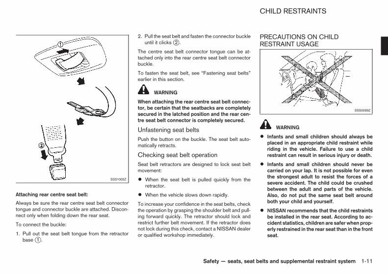
Attaching rear centre seat belt:
Always be sure the rear centre seat belt connectortongue and connector buckle are attached. Discon-nect only when folding down the rear seat.
To connect the buckle:
1. Pull out the seat belt tongue from the retractorbase j1 .
2. Pull the seat belt and fasten the connector buckleuntil it clicks j2 .
The centre seat belt connector tongue can be at-tached only into the rear centre seat belt connectorbuckle.
To fasten the seat belt, see “Fastening seat belts”earlier in this section.
WARNING
When attaching the rear centre seat belt connec-tor, be certain that the seatbacks are completelysecured in the latched position and the rear cen-tre seat belt connector is completely secured.
Unfastening seat beltsPush the button on the buckle. The seat belt auto-matically retracts.
Checking seat belt operationSeat belt retractors are designed to lock seat beltmovement:
• When the seat belt is pulled quickly from theretractor.
• When the vehicle slows down rapidly.
To increase your confidence in the seat belts, checkthe operation by grasping the shoulder belt and pull-ing forward quickly. The retractor should lock andrestrict further belt movement. If the retractor doesnot lock during this check, contact a NISSAN dealeror qualified workshop immediately.
PRECAUTIONS ON CHILDRESTRAINT USAGE
WARNING
• Infants and small children should always beplaced in an appropriate child restraint whileriding in the vehicle. Failure to use a childrestraint can result in serious injury or death.
• Infants and small children should never becarried on your lap. It is not possible for eventhe strongest adult to resist the forces of asevere accident. The child could be crushedbetween the adult and parts of the vehicle.Also, do not put the same seat belt aroundboth your child and yourself.
• NISSAN recommends that the child restraintsbe installed in the rear seat. According to ac-cident statistics, children are safer when prop-erly restrained in the rear seat than in the frontseat.
SSS1005Z
SSS0099Z
CHILD RESTRAINTS
Safety — seats, seat belts and supplemental restraint system 1-11

• Improper use or improper installation of achild restraint can increase the risk or sever-ity of injury for both the child and other occu-pants of the vehicle and can lead to seriousinjury or death in an accident.
• Follow all of the child restraint manufacturer’sinstructions for installation and use. Whenpurchasing a child restraint, be sure to selectone which will fit your child and vehicle. It maynot be possible to properly install some typesof child restraint in your vehicle.
• The direction of the child restraint, eitherfront-facing or rear-facing, depends on thetype of the child restraint and the size of thechild. Refer to the child restraint manufactur-er’s instructions for details.
• Adjustable seatbacks should be positioned tofit the child restraint, but as upright as pos-sible.
• After attaching a child restraint, test it beforeyou place the child in it. Push it from side toside and tug it forward to make sure that it isheld securely in place. The child restraintshould not move more than 25 mm (1 in). Ifthe restraint is not secure, tighten the belt asnecessary, or install the restraint in anotherseat and test it again.
• When the child restraint is not in use, keep itsecured with the ISOFIX child restraint sys-tem or a seat belt to prevent it from beingthrown around in case of a sudden stop oraccident.
• Never install a rear-facing child restraint onthe front passenger’s seat when the front pas-senger’s air bag is available. Supplementalfront-impact air bags inflate with great force.A rear-facing child restraint could be struckby the supplemental front-impact air bags inan accident and could seriously injure or killyour child.
• If the seat belt in the position where a childrestraint is installed requires a locking deviceand if it is not used, injuries could result froma child restraint tipping over during normalvehicle braking or cornering.
CAUTION
Remember that a child restraint left in a closedvehicle can become very hot. Check the seatingsurface and buckles before placing your child ina child restraint.
NISSAN recommends that infants and small chil-dren be seated in a child restraint. You shouldchoose a child restraint that fits your vehicle andalways follow the manufacturer’s instructions for in-stallation and use. In addition, there are many typesof child restraints available for larger children thatshould be used for maximum protection.
UNIVERSAL CHILD RESTRAINTS FORFRONT SEAT AND REAR SEATSWhen selecting any child restraint, keep the follow-ing points in mind:
• Choose a child restraint that complies with thelatest European safety standard, ECE Regula-tion 44.03.
• Place your child in the child restraint and checkthe various adjustments to be sure the child re-straint is compatible with your child. Always fol-low all of the recommended procedures.
• Check the child restraint in your vehicle to besure it is compatible with vehicle’s seat belt sys-tem.
• Refer to the tables later in this section for a list ofthe recommended fitment positions and the ap-proved child restraints for your vehicle.
1-12 Safety — seats, seat belts and supplemental restraint system

Approved child restraint positions
Age group
Seating positionFront pas-
senger seatwith air bag
(withdeactivated
front pas-senger air bag
ONLY)
Front pas-senger seat
without air bag
2nd centreseat
2nd outer seat 3rd outer seat
Group 0+< 13 kg (0 to 24
months)L* L* X L* or I* L*
Group I9 to 18 kg (9 to
48 months)L L X L or I L
Group II and III15 to 36 kg (4 to
12 years)L L X L L
U: Suitable for “Universal” category - front and rear facing child restraints - approved for use in this age group.
L: Suitable for particular child restraints given in the following table.
I: Suitable for “ISOFIX (with top tether)” category given in the following table.
*: Rearward facing only
Safety — seats, seat belts and supplemental restraint system 1-13

List of approved child restraintsWARNING
In vehicles equipped with a side air bag system,do not let any infants or small children sit in thefront passenger’s seat as the air bag may causeserious injury in case of deployment during a col-lision.
NOTE
Child restraints approved to ECE Regulation NO.44.03 are clearly marked with the categories suchas Universal, Semi-universal or ISOFIX.
ISOFIX CHILD RESTRAINT SYSTEM(where fitted)
Your vehicle is equipped with special anchor pointsthat are used with ISOFIX child restraint systems.
Age group
Seating positionFront pas-
senger seatwith air bag
(withdeactivated
front pas-senger air bag
ONLY)
Front pas-senger seat
without air bag
2nd centreseat
2nd outer seat 3rd outer seat
Group 0+< 13 kg (0 to 24
months)
Britax CosyTot*1, *2
Romer Baby-Safe*1, *2
Britax CosyTot*1, *2
Romer Baby-Safe*1, *2
—
Britax CosyTot*1, *2
Romer Baby-Safe*1, *2
Fair G 0/1*2,*3
Britax CosyTot*1, *2
Romer Baby-Safe*1, *2
Group I9 to 18 kg (9 to
48 months)
Britax/RomerDuo Plus*1
Britax/RomerDuo Plus*1
—Britax/RomerDuo Plus*1
Fair G 0/1*3
Britax/RomerDuo Plus*1
Group II and III15 to 36 kg (4 to
12 years)
Britax HiLiner*1
Romer Kid*1
Britax HiLiner*1
Romer Kid*1—
Britax HiLiner*1
Romer Kid*1
Britax HiLiner*1
Romer Kid*1
*1: Universal mode only.
*2: Rearward facing only.
*3: This is an ISOFIX child restraint. It requires an additional platform to be fitted to your vehicle:Rearward facing use Platform RWF DForward facing use Platform FWF BAlternatively, refer to a NISSAN dealer or qualified workshop for the latest platform references.
SSS0998Z
ISOFIX label location
1-14 Safety — seats, seat belts and supplemental restraint system

ISOFIX lower anchor point locationsThe ISOFIX anchor points are provided to installchild restraints in the second row outer seating po-sitions only. Do not attempt to install a child re-straint in the centre position using the ISOFIXanchors.
The ISOFIX anchors are located at the rear of theseat cushion near the seatback. A label is attachedto the seatback to help you locate the ISOFIX an-chors.
ISOFIX child restraint anchorattachmentsISOFIX child restraints include two rigid attach-ments that can be connected to two anchors lo-cated in the seat. With this system, you do not haveto use a vehicle seat belt to secure the child re-straint. Check your child restraint for a label statingthat it is compatible with the ISOFIX child restraints.This information may also be in the instructions pro-vided by the child restraint manufacturer.
ISOFIX child restraints generally require the use ofa top tether strap or other anti-rotation devices suchas support legs. When installing ISOFIX child re-straints, carefully read and follow the instructions inthis manual and those supplied with the child re-straints. (See “Child restraint installation usingISOFIX” later in this section.)
CHILD RESTRAINT ANCHORAGE(where fitted)Your vehicle is designed to accommodate a childrestraint system on the second row seat. When in-stalling a child restraint system, carefully read andfollow the instructions in this manual and those sup-plied with the child restraint system.
WARNING
Child restraint anchorages are designed to with-stand only those loads imposed by correctly fit-ted child restraints. Under no circumstances arethey to be used for adult seat belts, harnesses orfor attaching other items or equipment to thevehicle.
Anchorage locationThe anchor points are located on the seat cushionbehind the second row outer seating positions.
SSS0637Z
ISOFIX lower anchor location
SSS0644Z
Anchor attachment
SSS1000Z
Safety — seats, seat belts and supplemental restraint system 1-15

CHILD RESTRAINT INSTALLATIONUSING ISOFIX
WARNING
• Attach ISOFIX child restraints only at thespecified locations. For the ISOFIX lower an-chor locations, see “ISOFIX child restraint sys-tem (where fitted)” earlier in this section. If achild restraint is not secured properly, yourchild could be seriously injured or killed in anaccident.
• Do not install child restraints that require theuse of a top tether strap to seating positionsthat do not have a top tether anchor.
• Do not secure a child restraint in the centresecond row and third row seating positionsusing the ISOFIX lower anchors. The child re-straint will not be secured properly.
• Inspect the lower anchors by inserting yourfingers into the lower anchor area and feelingto make sure there are no obstructions overthe ISOFIX anchors, such as seat belt web-bing or seat cushion material. The child re-straint will not be secured properly if theISOFIX anchors are obstructed.
• Child restraint anchorages are designed towithstand only those loads imposed by cor-rectly fitted child restraints. Under no circum-stance are they to be used for adult seat belts,harnesses or for attaching other items orequipment to the vehicle.
Installation on second row outer seatsFront-facing:
Be sure to follow the manufacturer’s instructions forthe proper use of your child restraint. Follow thesesteps to install a front-facing child restraint on thesecond row outer seats using ISOFIX:
1. Position the child restraint on the seat j1 .
2. Secure the child restraint anchor attachments tothe ISOFIX lower anchors j2 .
3. The back of the child restraint should be securedagainst the vehicle seatback. If necessary, adjustor remove the head restraint to obtain the correctchild restraint fit. (See “Head restraints” earlier inthis section.) If the head restraint is removed,store it in a secure place. Be sure to install thehead restraint when the child restraint isremoved. If the seating position does not have anadjustable head restraint and it is interfering withthe proper child restraint fit, try another seatingposition or a different child restraint.
4. Shorten the rigid attachment to have the childrestraint firmly tightened; press downward j3and rearward j4 firmly in the centre of the childrestraint with your knee to compress the vehicleseat cushion and seatback.
5. If the child restraint is equipped with a top tetherstrap, route the top tether strap and secure thetether strap to the tether anchor point. (See“Child restraint anchorage (where fitted)” earlierin this section.)
6. If the child restraint is equipped with other anti-rotation devices such as support legs, use theminstead of the top tether strap following the childrestraint manufacturer’s instructions.
SSS0646AZ
Steps 1 and 2
SSS0754AZ
Step 4
1-16 Safety — seats, seat belts and supplemental restraint system

7. Test the child restraint before you place the childin it j5 . Push the child restraint from side to sideand tug it forward to make sure that it is heldsecurely in place.
8. Check to make sure that the child restraint isproperly secured prior to each use. If the childrestraint is loose, repeat steps 3 through 7.
Rear-facing:
Be sure to follow the manufacturer’s instructions forthe proper use of your child restraint. Follow thesesteps to install a rear-facing child restraint on therear outer seats using ISOFIX:
1. Position the child restraint on the seat j1 .
2. Secure the child restraint anchor attachments tothe ISOFIX lower anchors j2 .
3. Shorten the rigid attachment to have the childrestraint firmly tightened; press downward j3and rearward j4 firmly in the centre of the childrestraint with your hand to compress the vehicleseat cushion and seatback.
4. If the child restraint is equipped with a top tetherstrap, route the top tether strap and secure thetether strap to the tether anchor point. (See“Child restraint anchorage (where fitted)” earlierin this section.)
5. If the child restraint is equipped with other anti-
rotation devices such as support legs, use theminstead of the top tether strap following the childrestraint manufacturer’s instructions.
6. Test the child restraint before you place the childin it j5 . Push the child restraint from side to sideand tug it forward to make sure that it is heldsecurely in place.
7. Check to make sure that the child restraint isproperly secured prior to each use. If the childrestraint is loose, repeat steps 3 through 6.
SSS0755AZ
Step 7
SSS0649AZ
Steps 1 and 2
SSS0756AZ
Step 3
SSS0757AZ
Step 6
Safety — seats, seat belts and supplemental restraint system 1-17

CHILD RESTRAINT INSTALLATIONUSING 3-POINT TYPE SEAT BELT
Installation on rear seatsFront-facing:
Be sure to follow the manufacturer’s instructions forthe proper use of your child restraint. Follow thesesteps to install a front-facing child restraint on therear seats using 3-point type seat belt without auto-matic locking mode:
1. Position the child restraint on the seat j1 .
2. Route the seat belt tongue through the child re-straint and insert it into the buckle j2 until youhear and feel the latch engage.
3. To prevent slack in the seat belt webbing, it isnecessary to secure the seat belt in place withlocking devices attached to the child restraint.
4. Remove any additional slack from the seat belt;
press downward j3 and rearward j4 firmly inthe centre of the child restraint with your knee tocompress the vehicle seat cushion and seatbackwhile pulling up on the seat belt.
5. Test the child restraint before you place the childin it j5 . Push the child restraint from side to sideand tug it forward to make sure that it is heldsecurely in place.
6. Check to make sure that the child restraint isproperly secured prior to each use. If the childrestraint is loose, repeat steps 3 through 5.
SSS0758AZ
Step 1
SSS0493AZ
Step 2
SSS0647AZ
Step 4
SSS0638AZ
Step 5
1-18 Safety — seats, seat belts and supplemental restraint system

Rear-facing:
Be sure to follow the manufacturer’s instructions forthe proper use of your child restraint. Follow thesesteps to install a rear-facing child restraint on therear seats using 3-point type seat belt without auto-matic locking mode:
1. Position the child restraint on the seat j1 .
2. Route the seat belt tongue through the child re-straint and insert it into the buckle j2 until youhear and feel the latch engage.
3. To prevent slack in the seat belt webbing, it isnecessary to secure the seat belt in place withlocking devices attached to the child restraint.
4. Remove any additional slack from the seat belt;press downward j3 and rearward j4 firmly inthe centre of the child restraint with your hand tocompress the vehicle seat cushion and seatbackwhile pulling up on the seat belt.
5. Test the child restraint before you place the childin it j5 . Push the child restraint from side to sideand tug it forward to make sure that it is heldsecurely in place.
6. Check to make sure that the child restraint isproperly secured prior to each use. If the childrestraint is loose, repeat steps 3 through 5.
SSS0759AZ
Step 1
SSS0654AZ
Step 2
SSS0639AZ
Step 4
SSS0658AZ
Step 5
Safety — seats, seat belts and supplemental restraint system 1-19

Installation on front passenger’s seat
WARNING
• Never install a rear-facing child restraint onthe front passenger’s seat when the front pas-senger’s air bag is available. Supplementalfront-impact air bags inflate with great force.A rear-facing child restraint could be struckby the supplemental front-impact air bags inan accident and could seriously injure or killyour child.
• Never install a child restraint with a top tetherstrap on the front seat.
• NISSAN recommends that a child restraint beinstalled on the rear seat. However, if youmust install a child restraint on the front pas-senger’s seat, move the passenger’s seat tothe rearmost position.
• Child restraints for infants must be used inthe rear-facing direction and therefore must
not be used on the front passenger’s seatwhen the front passenger’s air bag is avail-able.
Front-facing:
Be sure to follow the manufacturer’s instructions forthe proper use of your child restraint. Follow thesesteps to install a front-facing child restraint on thefront passenger’s seat using 3-point type seat beltwithout automatic locking mode:
If you must install a front-facing child restraint sys-tem on the front seat, follow these steps:
1. For models with the supplemental front-impactpassenger’s air bag, turn off the front passen-ger’s air bag using the front passenger air bagswitch. (See “Supplemental air bag systems”later in this section.) Turn the ignition switch tothe ON position and make sure that the front airbag status light on the instrument panel illu-minates.
2. Move the seat to the rearmost position j1 .
3. Adjust the head restraint to its highest positionj2 .
4. Position the child restraint in the seat.
5. Route the seat belt tongue through the child re-straint and insert it into the buckle j3 until youhear and feel the latch engage.
6. To prevent slack in the seat belt webbing, it isnecessary to secure the seat belt in place withlocking devices attached to the child restraint.
SSS0300AZ
SSS0627Z
Steps 2 and 3 SSS0360CZ
Step 5
1-20 Safety — seats, seat belts and supplemental restraint system

7. Remove any additional slack from the seat belt;press downward j4 and rearward j5 firmly inthe centre of the child restraint with your knee tocompress the vehicle seat cushion and seatbackwhile pulling up on the seat belt.
8. Test the child restraint before you place the childin it j6 . Push the child restraint from side to sideand tug it forward to make sure that it is heldsecurely in place.
9. Check to make sure that the child restraint isproperly secured prior to each use. If the childrestraint is loose, repeat steps 6 through 8.
PRECAUTIONS ON SUPPLEMENTALRESTRAINT SYSTEM (SRS)This Supplemental Restraint System (SRS) sectioncontains important information concerning the driv-er’s and passenger’s supplemental front-impact airbags, supplemental side-impact air bags and pre-tensioner seat belts.
Supplemental front-impact air bagsystemThis system can help cushion the impact force tothe head and chest area of the driver and/or frontpassenger (where fitted) in certain frontal collisions.The supplemental front-impact air bag is designedto inflate on the front where the vehicle is impacted.
Supplemental side-impact air bagsystem (where fitted)This system can help cushion the impact force tothe chest area of the driver and front passenger incertain side-impact collisions. The supplementalside-impact air bag is designed to inflate on the sidewhere the vehicle is impacted.
The SRS is designed to supplement the accidentprotection provided by the driver’s and passenger’sseat belts and is not designed to substitute forthem. The SRS can help save lives and reduce seri-ous injuries. However, inflating air bags may causeabrasions or other injuries. Air bags do not provideprotection to the lower body. Seat belts should al-ways be correctly worn and the occupants shouldalways be seated a suitable distance away from thesteering wheel and instrument panel. (See “Seat
SSS0647BZ
Step 7
SSS0302GZ
Step 8
SUPPLEMENTAL RESTRAINTSYSTEM (SRS)
Safety — seats, seat belts and supplemental restraint system 1-21

belts” earlier in this section). The air bags inflatequickly in order to help protect the occupants. Theforce of the air bags inflating can increase the risk ofinjury if the occupants are too close to, or areagainst, the air bag modules during inflation. The airbags will deflate quickly after deployment.
The SRS operates only when the ignition switchis in the ON or START position.
When the ignition switch is in the ON position,the SRS air bag warning light illuminates forabout 7 seconds and then turns off. This indi-cates that the SRS air bag system is operational.(See “SRS air bag warning light” later in this sec-tion.)
WARNING
• The supplemental front-impact air bags ordi-narily will not inflate in the event of a sideimpact, rear impact, rollover, or lower sever-ity frontal collision. Always wear the seat beltsto help reduce the risk or severity of injury inaccidents.
• The seat belts and the supplemental front-im-pact air bags are most effective when you aresitting well back and upright in the seat. Thefront-impact air bags inflate with great force.If you and your passengers are unrestrained,leaning forward, sitting sideways, or out ofposition in any way, you and your passengersare at greater risk of injury or death in an acci-dent. You and your passengers may also re-ceive serious or fatal injuries from the supple-mental front-impact air bag if you are upagainst it when it inflates. Always sit back
against the seatback and as far away as prac-tical from the steering wheel or instrumentpanel. Always use the seat belts.
WARNING
• Never let children ride unrestrained or extendtheir hands or face out of the window. Do notattempt to hold them in your lap or arms.Some examples of dangerous riding positionsare shown in the illustrations.
NPA930Z
Sit upright and well back
NPA926Z
Correct (rear) seating positions
1-22 Safety — seats, seat belts and supplemental restraint system

• Children may be severely injured or killedwhen the supplemental front-impact air bags,supplemental side-impact air bags, or supple-mental curtain side-impact air bags inflate ifthey are not properly restrained.
• Never install a rear-facing child restraint sys-tem on the front seat. An inflating supplemen-tal front-impact air bag could seriously injureor kill your child. (See “Child restraints” ear-lier in this section.)
WARNING
• The supplemental side-impact air bags(where fitted) ordinarily will not inflate in theevent of a front impact, rear impact, rollover,or lower severity side collision. Always wearthe seat belts to help reduce the risk or sever-ity of injury in accidents.
• The seat belts and the supplemental side-im-pact air bags are most effective when you aresitting well back and upright in the seat. The
supplemental side-impact air bags inflate withgreat force. If you and your passengers areunrestrained, leaning forward, sitting side-ways, or out of position in any way, you andyour passengers are at greater risk of injuryor death in an accident.
• Do not allow anyone to place their hands, legs,or face near the supplemental side-impact airbags on the sides of the seatback of the frontseats. Do not allow anyone sitting in the frontseats to extend their hands out of the win-dows or lean against the doors. Some ex-amples of dangerous riding positions areshown in the illustrations.
• When sitting in the rear seats, do not holdonto the seatback of the front seats. If thesupplemental side-impact air bags inflate, youmay be seriously injured. Be especially care-ful with children, who should always be prop-erly restrained.
• Do not use seat covers on the front seatbacks.They may interfere with the supplementalside-impact air bag inflations.
Pre-tensioner seat belt systemThe pre-tensioner seat belt system activates in con-junction with the supplemental front-impact air bag.Working with the seat belt retractor and anchor, ithelps tighten the seat belt the instant the vehiclebecomes involved in certain types of collisions, help-ing to restrain front seat occupants. (See “Pre-tensioner seat belt system” later in this section.)
Air bag warning labelsWarning labels about the supplemental air bag sys-tem are placed in the vehicle as shown in the illus-tration.
SRS air bag:
The warning label j1 is located on the surface ofthe passenger’s sun visor.
SRS front-impact passenger air bag (where fit-ted):
The warning label j2 is located on the side of thepassenger’s side instrument panel.
This label warns you not to fit a rear-facing childrestraint system on the front passenger seat as sucha restraint system used in this position could causeserious injury to the infant in case of air bag deploy-ment during a collision.
In vehicles equipped with a front-impact passengerair bag system, use a rear-facing child restraint sys-tem only on the rear seats.
SSS0100Z
SSS1029Z
Safety — seats, seat belts and supplemental restraint system 1-23

“Extreme Hazard! Do not use a rearward facing childrestraint on a seat protected by an air bag in front ofit!”
When installing a child restraint system in your ve-hicle, always follow the child restraint system manu-facturer’s instructions for installation.
For additional information, see “Child restraints”earlier in this section.
SRS air bag warning lightThe SRS air bag warning light, displaying inthe instrument panel, monitors the circuits of thesupplemental front-impact air bag, supplementalside-impact air bag and pre-tensioner seat belt sys-tems. The circuits monitored by the SRS air bagwarning light are the diagnosis sensor unit, crashzone sensor, satellite sensors, front-impact air bagmodules, side-impact air bag modules, pre-tensioner seat belts and all related wiring.
When the ignition switch is in the ON or STARTposition, the SRS air bag warning light illuminates
for about 7 seconds and then turns off. This indi-cates that the SRS air bag systems are operational.
If any of the following conditions occur, the air bagand/or pre-tensioner seat belt systems need servic-ing:
• The SRS air bag warning light remains on afterapproximately 7 seconds.
• The SRS air bag warning light flashes intermit-tently.
• The SRS air bag warning light does not illumi-nate at all.
Under these conditions, the supplemental front-im-pact air bag, supplemental side-impact air bag, orpre-tensioner seat belt systems may not operateproperly. They must be checked and repaired. Con-tact a NISSAN dealer or qualified workshop imme-diately.SPA1097Z
1-24 Safety — seats, seat belts and supplemental restraint system

1. Crash zone sensor
2. Supplemental front-impact air bag modules(Driver’s and front passenger’s) (where fitted)
3. Supplemental side-impact air bag modules(where fitted)
4. Diagnosis sensor unit
5 Satellite sensors (where fitted)
6. Seat belt pre-tensioner retractors
SUPPLEMENTAL AIR BAG SYSTEMS
WARNING
• Do not place any objects on the steering wheelpad, the instrument panel and the front seats.Do not place any objects between any occu-
pants and the steering wheel pad, on the in-strument panel and the front seats. Such ob-jects may become dangerous projectiles andcause injury if a supplemental air bag inflates.
• Immediately after inflation, several supple-mental air bag system components will be hot.Do not touch them: you may severely burnyourself.
• No unauthorised changes should be made toany components or wiring of the supplemen-tal air bag systems. This is to prevent acci-dental inflation of the supplemental air bagsor damage to the supplemental air bag sys-tems.
• Do not make unauthorised changes to yourvehicle’s electrical system, suspension sys-tem, front end structure, and side panels. Thiscould affect proper operation of the supple-mental air bag systems.
• Tampering with the supplemental air bag sys-tems may result in serious personal injury.Tampering includes changes to the steeringwheel and the instrument panel by placingmaterials over the steering wheel pad andabove, around or on the instrument panel orby installing additional trim materials aroundthe supplemental air bag systems.
• Work around and on the supplemental air bagsystems should be done by a NISSAN dealeror qualified workshop. The SRS wiring shouldnot be modified or disconnected. Unautho-
SSS0705
Safety — seats, seat belts and supplemental restraint system 1-25

rised electrical test equipment and probingdevices should not be used on the supple-mental air bag systems.
• The SRS wiring harness connectors are yel-low and/or orange for easy identification.
When the air bags inflate, a fairly loud noise may beheard, followed by the release of smoke. This smokeis not harmful and does not indicate a fire. Careshould be taken not to inhale it, as it may cause irri-tation and choking. Those with a history of a breath-ing condition should get fresh air promptly.
Supplemental front-impact air bagsystemThe driver’s supplemental front-impact air bag islocated at the centre of the steering wheel. The pas-senger’s supplemental front-impact air bag (ifequipped) is located at the instrument panel abovethe glove box.
The supplemental front-impact air bag system is de-signed to inflate in higher severity frontal collisions,although it may inflate if the forces in another type ofcollision are similar to those of a higher severity fron-tal impact. It may not inflate in certain frontal colli-sions. Vehicle damage (or lack of it) is not always anindication of proper supplemental front-impact airbag system operation.
Front passenger air bag status light (where fit-ted):
When the ignition switch is in the ON position, thefront passenger air bag status light on the instru-ment panel illuminates for about 7 seconds and thenturns off. This indicates that the front passenger airbag system is operational.
When the front passenger air bag is turned off withthe front passenger air bag switch, the front pas-senger air bag status light will illuminate and remainon as long as the front passenger air bag switch isin the OFF position.
WARNING
If any of the following conditions occur after theignition switch is turned to the ON position, havethe system checked, and if necessary repaired,by a NISSAN dealer or qualified workshoppromptly.
• The front passenger air bag status light re-mains on after approximately 7 seconds.
• The front passenger air bag status light doesnot illuminate at all.
Unless checked and repaired, the front passen-ger air bag system may not function properly.
Front passenger air bag switch (where fitted):
The front passenger air bag can be turned off withthe front passenger air bag switch jA located onthe side of the instrument panel on the front passen-ger’s side.
To turn off the front passenger air bag:
1. Turn the ignition switch to the “OFF” position.
2. Insert the key into the front passenger air bagswitch. For Intelligent Key equipped models, see“Keys” in the “3. Pre-driving checks andadjustments” section for mechanical key usage.
3. Push and turn the key to the OFF position.
SSS0909Z
SSS1004Z
1-26 Safety — seats, seat belts and supplemental restraint system

4. Turn the ignition switch to the ON position. Thefront passenger air bag status light will illuminateand remain on.
To turn on the front passenger air bag:
1. Turn the ignition switch to the “OFF” position.
2. Insert the key into the front passenger air bagswitch.
3. Push and turn the key to the ON position.
4. Turn the ignition switch to the ON position. Thefront passenger air bag status light will illuminatethen turn off.
Supplemental side-impact air bagsystem (where fitted)The supplemental side-impact air bag is located atthe outside of the front seats’ seatbacks.
The supplemental side-impact air bag system is de-signed to inflate in higher severity side collisions,although it may inflate if the forces in another type of
collision are similar to those of a higher severity sideimpact. It may not inflate in certain side collisions.Vehicle damage (or lack of it) is not always an indi-cation of proper supplemental side-impact air bagsystem operation.
PRE-TENSIONER SEAT BELTSYSTEM (where fitted)
WARNING
• The pre-tensioner seat belt cannot be reusedafter activation. It must be replaced togetherwith the retractor and buckle as a unit.
• If the vehicle becomes involved in a collisionbut the pre-tensioner is not activated, be sureto have the pre-tensioner system checkedand, if necessary, replaced by a NISSANdealer or qualified workshop.
• No unauthorised changes should be made toany components or wiring of the pre-tensionerseat belt system. This is to prevent accidentalactivation of the pre-tensioner seat belt ordamage to the pre-tensioner seat belt sys-tem.
• Work around or on the pre-tensioner seat beltsystem should be done by a NISSAN dealer orqualified workshop. The SRS wiring shouldnot be modified or disconnected. Unautho-rised electrical test equipment and probingdevices should not be used on the pre-ten-sioner seat belt system.
• If you need to dispose of the pre-tensionerseat belt system, or scrap the vehicle, contacta NISSAN dealer or qualified workshop. Cor-rect pre-tensioner disposal procedures areset forth in the appropriate NISSAN ServiceManual. Incorrect disposal procedures couldcause personal injury.
The pre-tensioner is encased with the front seatbelt’s retractor and anchor. These seat belts areused the same as conventional seat belts.
When the pre-tensioner seat belt activates, a fairlyloud noise may be heard, followed by the release ofsmoke. This smoke is not harmful and does not indi-cate a fire. Care should be taken not to inhale it, asit may cause irritation and choking. Those with a his-tory of a breathing condition should get fresh airpromptly.
REPAIR AND REPLACEMENTPROCEDURE
WARNING
• Once the air bags have been inflated, the airbag modules will not function and must bereplaced. The air bag modules must be re-placed by a NISSAN dealer or qualified work-shop. The inflated air bag modules cannot berepaired.
• The air bag systems should be inspected by aNISSAN dealer or qualified workshop if thereis any damage to the front end portion of thevehicle.
SSS0711Z
Safety — seats, seat belts and supplemental restraint system 1-27

• If you need to dispose of the SRS or scrap thevehicle, contact a NISSAN dealer or qualifiedworkshop. Correct disposal procedures areset forth in the appropriate NISSAN ServiceManual. Incorrect disposal procedures couldcause personal injury.
The air bags and pre-tensioner seat belts are de-signed to activate on a one-time-only basis. As areminder, unless the SRS air bag warning light isdamaged, the SRS air bag warning light remainsilluminated after inflation has occurred. The repairand replacement of the SRS should be done only bya NISSAN dealer or qualified workshop.
When maintenance work is required on the vehicle,information about the air bags, pre-tensioner seatbelts and related parts should be pointed out to theperson performing the maintenance. The ignitionswitch should always be in the LOCK position whenworking under the bonnet or inside the vehicle.
1-28 Safety — seats, seat belts and supplemental restraint system

2 Instruments and controlsInstruments and controls
Meters and gauges .................................................. 2-2Speedometer...................................................... 2-2Odometer........................................................... 2-2Fuel gauge ......................................................... 2-2Instrument brightness control.............................. 2-3
Vehicle information display ....................................... 2-4Indicators for operation (for model withIntelligent Key system) ........................................ 2-4Warnings and alerts............................................ 2-5Indicators for maintenance.................................. 2-6Trip computer ..................................................... 2-6Engine oil level information display ...................... 2-9
Warning/indicator lights and audible reminders ........ 2-10Checking bulbs .................................................. 2-10Warning lights .................................................... 2-11Indicator lights .................................................... 2-14Audible reminders............................................... 2-16
Headlight and turn signal switch............................... 2-17Headlight switch ................................................. 2-17Headlight aiming control ..................................... 2-18Battery saver system........................................... 2-20Turn signal switch............................................... 2-21
Fog light switch ....................................................... 2-21Front fog lights (where fitted) .............................. 2-21Rear fog light ...................................................... 2-21
Wiper and washer switch ........................................ 2-22Windscreen wiper and washer switch................. 2-22Rain-sensing auto wiper system (where fitted)..... 2-23Rear window wiper and washer switch (wherefitted).................................................................. 2-23
Defogger switch (where fitted) ................................. 2-24Hazard indicator flasher switch ................................ 2-24Horn ........................................................................ 2-25Windows ................................................................. 2-25
Manual windows (where fitted) ........................... 2-25Sliding windows (where fitted) ............................ 2-25Power windows (where fitted)............................. 2-25
Clock ...................................................................... 2-27Adjusting time..................................................... 2-27
Power outlet ............................................................ 2-27Ashtray .................................................................... 2-28Storage ................................................................... 2-28
Glove box ........................................................... 2-28Console box ....................................................... 2-29Under-seat tray (where fitted).............................. 2-29Bottle holders (where fitted)................................ 2-29Cup holders ....................................................... 2-29Personal table (where fitted) ............................... 2-30Hooks ................................................................ 2-30Card holder ........................................................ 2-31Ticket holders..................................................... 2-31Utility hook.......................................................... 2-31Luggage hooks................................................... 2-32Tonneau cover (where fitted) .............................. 2-32Partition (where fitted)......................................... 2-33
Sun visors ............................................................... 2-33Interior lights............................................................ 2-34
Room light .......................................................... 2-34Luggage compartment light ................................ 2-34

For an overview of the instruments and controlssee “Meters and gauges” in the “0. Illustratedtable of contents” section.
SPEEDOMETER
The speedometer indicates the vehicle speed (km/hor MPH).
ODOMETER
Odometer/Twin trip odometerThe odometer/twin trip odometer is displayed whenthe ignition switch is in the ON position.
The odometer j1 displays the total distance thevehicle has been driven.
The twin trip odometer j2 displays the distance ofindividual trips.
Changing twin trip odometer display:
Push the reset switch j3 to change the display asfollows:
TRIP A → TRIP B → TRIP A
Resetting twin trip odometer:
Push the reset switch j3 for more than 1 second toreset the trip odometer to zero.
FUEL GAUGE
The fuel gauge jA on the vehicle information displayindicates the approximate fuel level in the tank whenthe ignition switch is in the ON position.
The gauge may move slightly during braking, turn-ing, accelerating, or going up and down hills due tomovement of fuel in the tank.
The fuel gauge indicator jB changes to the low fuelwarning jC when the fuel level in the tank is getting
SIC4195Z
Type A
SIC4486Z
Type B
SIC4270Z
Type C
SIC4197Z
SIC4198Z
METERS AND GAUGES
2-2 Instruments and controls

low. Refuel as soon as it is convenient, preferablybefore the gauge reads the empty (0) level.
The arrow, , indicates the fuel filler lid is lo-cated on the right side of the vehicle.
CAUTION
Refuel before the gauge reads the empty (0) po-sition.
There is a small reserve of fuel in the tank when thefuel gauge reads the empty (0) position.
INSTRUMENT BRIGHTNESSCONTROL
The instrument brightness control switch can be op-erated when the ignition switch and the headlightswitch are in the ON position.
Turn the control j1 to brighten or dim the meterpanel lights.
When the brightness level reaches the maximum orminimum, a beep will sound.
The vehicle information display shows the bright-ness level j2 .
The display returns to the normal display when theinstrument brightness control switch is not operatedfor more than 5 seconds.
The instrument brightness level will not be displayedand the control switch cannot be operated when thealert or maintenance information is displayed in thevehicle information display.
SIC4199
Instruments and controls 2-3

The vehicle information display j1 displays the fol-lowing items:
• Indicators for operation (for model with Intelli-gent Key system)
• Warnings and alerts
• Indicators for maintenance
• Trip computer
• Setting
• Clock
• Upshift indicator (See “Driving vehicle” in the“5. Starting and driving” section.)
• Engine oil level information
• Odometer (See “Odometer” earlier in this sec-tion.)
• Fuel gauge (See “Fuel gauge” earlier in this sec-tion.)
• Instrument brightness control (See “Instrumentbrightness control” earlier in this section.)
• Rear view monitor (where fitted) (See “Rear viewmonitor (where fitted)” in the “4. Display screen,heater and air conditioner, and audio system”section.)
INDICATORS FOR OPERATION (formodel with Intelligent Key system)
1. [NO KEY] warningThis warning appears in either of the following con-ditions.
No key inside the vehicle:
The warning appears when the door is closed withthe key left outside the vehicle and the ignition switchin the ACC or ON position. Make sure that the keyis inside the vehicle.
Unregistered key:
The warning appears when the ignition switch isturned from the LOCK position and the key cannotbe recognised by the system. You cannot start theengine with an unregistered key. Use the registeredkey.
2. Key battery discharge indicatorThis indicator appears when the key battery is run-ning out of power.
If this indicator appears, replace the battery with anew one. (See “Intelligent key battery” in the“8. Maintenance and do-it-yourself” section.)
3. LOCK warningThe warning appears when the ignition switch is leftin the ACC or “OFF” position instead of completelybeing turned to the LOCK position.
If this warning appears, turn the ignition switch tothe LOCK position while pushing the PUSH releasebutton.
The warning will turn off in approximately 5 minutes.
SIC4196Z
SIC4212
VEHICLE INFORMATION DISPLAY
2-4 Instruments and controls

At the same time, the Intelligent Key lock warninglight in the meter will blink for approximately 5 min-utes and then turn off.
WARNINGS AND ALERTS
The design of the warnings and alerts may differdepending on the model.
1. Parking brake release warningThis warning appears when the vehicle speed isabove 7 km/h (4 MPH) and the parking brake isapplied.
2. Low fuel warningThis warning appears when the fuel level in the tankis getting low. Refuel as soon as it is convenient,preferably before the fuel gauge reaches the empty(0) position.
There is a small reserve of fuel remaining in thetank when the fuel gauge reaches the empty (0)position.
3. Door open warningThis warning appears if any of the doors (includingthe back door) are open or not closed securely. Thevehicle icon indicates which door is open on the dis-play.
4. Time alertThis alert appears when the set time is reached.You can set the time for up to 6 hours in the settingmenu. (See “Trip computer” later in this section.)
5. Speed alertThis alert appears when the set speed is reached.The speed can be set in the setting menu. (See“Trip computer” later in this section.) The displaymay differ from the speedometer indication.
6. Idling alertThis alert appears when the set idling time isreached. The time can be set in the setting menu.(See “Trip computer” later in this section.)
7. Upshift indicatorThis indicator appears when the set engine speed(RPM) for upshift is reached. The speed can be setin the setting menu. (See “Trip computer” later inthis section and “Driving vehicle” in the “5. Startingand driving” section.)
SIC4213
Instruments and controls 2-5

INDICATORS FOR MAINTENANCE
The design of the indicators may differ dependingon the model.
See “Trip computer” later in this section for the set-ting of each indicator.
1. [ENGINE OIL] replacement indicatorThis indicator appears when the set time comes forchanging the engine oil. You can set or reset thedistance for changing the engine oil.
2. [OIL FILTER] replacement indicatorThis indicator appears when the set time comes forreplacing the oil filter. You can set or reset the dis-tance for replacing the oil filter.
3. [TIRE] replacement indicatorThis indicator appears when the set time comes forreplacing tyres. You can set or reset the distance forreplacing tyres.
4. [OTHER] indicatorThis indicator appears when the set time comes forreplacing items other than the engine oil, oil filterand tyres. You can set or reset the distance forreplacing the items.
TRIP COMPUTER
To operate the trip computer, push the mode switchjA .
Each time the switch jA is pushed, the display willchange as follows:
Tachometer → Current fuel consumption → Aver-age fuel consumption and speed → Elapsed timeand trip odometer → Distance to empty → Setting
The design of each display may differ depending onthe model.
SIC4214
SIC4215Z
2-6 Instruments and controls

TachometerThe tachometer indicates the engine speed in revo-lutions per minute (rpm). Do not rev the engineinto the red zone j1 .
The red zone varies depending on the model.
Current fuel consumption (l (litre)/100km or MPG)The current fuel consumption mode shows the cur-rent fuel consumption.
Average fuel consumption (l (litre)/100km or MPG) and speed (km/h or MPH)Fuel consumption:
The average fuel consumption mode shows the av-erage fuel consumption since the last reset. Reset-ting is done by pushing the mode switch jA forlonger than 1 second. (The average speed is alsoreset at the same time.)
The display is updated every 30 seconds. At aboutthe first 1/3 mile (500 m) after a reset, the displayshows “——”.
Speed:
The average speed mode shows the average ve-hicle speed since the last reset. Resetting is doneby pushing the mode switch jA for longer than 1second. (The average fuel consumption is also resetat the same time.)
The display is updated every 30 seconds. The first30 seconds after a reset, the display shows “——”.
SIC4216Z
Petrol engine model
SIC4485Z
Diesel engine model
SIC4241Z
SIC4242Z
Instruments and controls 2-7
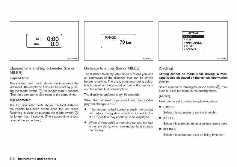
Elapsed time and trip odometer (km orMILES)Elapsed time:
The elapsed time mode shows the time since thelast reset. The displayed time can be reset by push-ing the mode switch jA for longer than 1 second.(The trip odometer is also reset at the same time.)
Trip odometer:
The trip odometer mode shows the total distancethe vehicle has been driven since the last reset.Resetting is done by pushing the mode switch jAfor longer than 1 second. (The elapsed time is alsoreset at the same time.)
Distance to empty (km or MILES)The distance to empty (dte) mode provides you withan estimation of the distance that can be drivenbefore refuelling. The dte is constantly being calcu-lated, based on the amount of fuel in the fuel tankand the actual fuel consumption.
The display is updated every 30 seconds.
When the fuel level drops even lower, the dte dis-play will change to “----”.
• If the amount of fuel added is small, the displayjust before the ignition switch is turned to the“OFF” position may continue to be displayed.
• When driving uphill or rounding curves, the fuelin the tank shifts, which may momentarily changethe display.
[Setting]Setting cannot be made while driving. A mes-sage is also displayed on the vehicle informationdisplay.
Select a menu by rotating the mode switch jA , thenpush it to set the menu in the setting mode.
[ALERT]:
Alert can be set to notify the following items.
• [TIMER]
Select this submenu to set the time alert.
• [SPEED]
Select this submenu to set a vehicle speed alert.
• [IDLING]
Select this submenu to set an idling time alert.
SIC4243Z SIC4484Z SIC4218Z
2-8 Instruments and controls

• [UPSHIFT]
Select this submenu to set the engine speed(RPM) of the upshift indicator. (See “Drivingvehicle” in the “5. Starting and driving” section.)
To return to the top page of the setting mode, select[BACK].
[MAINTENANCE]:
The maintenance intervals of the following items canbe set or reset for the reminders.
• [ENGINE OIL]
Select this submenu to set or reset the distancefor changing the engine oil.
• [OIL FILTER]
Select this submenu to set or reset the distancefor replacing the oil filter.
• [TIRE]
Select this submenu to set or reset the distancefor replacing tyres.
• [OTHER]
Select this submenu and set or reset the dis-tance for replacing items other than the engineoil, oil filter and tyres.
To return to the top page of the setting mode, select[BACK].
[CLOCK]:
Clock adjustment can be set.
• [12h, 24h]
Select this submenu to set the 12h/24h time dis-play mode.
• [SETTING]
Adjust the time (hour and minute) of the clock onthe meter.
• [DISPLAY]
Select this submenu to set the clock display toON/OFF.
To return to the top page of the setting mode, select[BACK].
[OPTIONS] (where fitted):
The following items can be set to your preference.
• [LANGUAGE]
Select this submenu to choose the language forthe display.
• [UNIT]
Select this submenu to choose the unit (km/l,l/100 km, etc.) for the display.
To return to the top page of the setting mode, select[BACK].
ENGINE OIL LEVEL INFORMATIONDISPLAY
When the ignition switch is turned to the ON posi-tion, the engine oil level information will be displayedas follows:
[OIL LEVEL GOOD] j1 : Oil level is sufficient fordriving and the oil level will be displayed.
[OIL LEVEL LOW] j2 : Oil level is low. Oil needs tobe added immediately.
CAUTION
The engine oil level should be checked regularly.Operating with an insufficient amount of oil candamage the engine and such damage is not cov-ered by the warranty.
For checking the engine oil level and adding oil, see“Engine oil” in the “8. Maintenance anddo-it-yourself” section.
SIC4217Z
Instruments and controls 2-9

Anti-lock Braking System (ABS) warn-ing light
Malfunction warning light (red) (dieselengine model)
Low temperature indicator light (green)
Brake warning light Seat belt warning light Malfunction Indicator Light (MI or MIL)(orange)
Charge warning light Supplemental Restraint System (SRS)air bag warning light
Rear fog light indicator light
Door open warning light Water-in-fuel-filter warning light (dieselengine model)
Security indicator light
Electric power steering warning light Electronic Stability Programme (ESP)off indicator light*
Slip indicator light*
Engine oil pressure warning light Front passenger air bag status light* Trailer direction indicator light
High temperature warning light (red) Front fog lights indicator light* Turn signals/hazard indicator lights
Intelligent Key lock warning light* Glow plug indicator light (diesel enginemodel)
*: where fitted
Intelligent Key system warning light* High beam indicator light
CHECKING BULBSWith all doors closed, apply the parking brake, fas-ten the seat belts and turn the ignition switch to theON position without starting the engine. Where fit-ted, the following lights will illuminate: , ,
, , .
Where fitted, the following lights will illuminate briefly
and then turn off: , (red), , ,, , (green), , , .
If any lights fail to illuminate, it may indicate a burned-out bulb or an open circuit in the electrical system.Have the system checked, and if necessary re-paired, by a NISSAN dealer or qualified workshoppromptly.
Some indicators and warnings are also displayed onthe vehicle information display. (See “Vehicle infor-mation display” earlier in this section.)
WARNING/INDICATOR LIGHTS AND AUDIBLE REMINDERS
2-10 Instruments and controls

WARNING LIGHTS
Anti-lock Braking System (ABS)warning light
When the ignition switch is in the ON position, theAnti-lock Braking System (ABS) warning light illumi-nates and then turns off. This indicates the ABS isoperational.
If the ABS warning light illuminates while the engineis running, or while driving, it may indicate the ABSis not functioning properly. Have the systemchecked by a NISSAN dealer or qualified workshoppromptly.
If an ABS malfunction occurs, the anti-lock functionis turned off. The brake system then operates nor-mally, but without anti-lock assistance. (See “Brakesystem” in the “5. Starting and driving” section.)
Brake warning light
WARNING
• If the brake fluid level is below the minimummark on the brake fluid reservoir, do not drivethe vehicle until the brake system has beenchecked by a NISSAN dealer or qualifiedworkshop.
• Even if you judge it to be safe, have your ve-hicle towed because driving it could be dan-gerous.
• Depressing the brake pedal without the en-gine running and/or with a low brake fluid
level could increase the stopping distance andrequire greater pedal travel distance and ef-fort.
The brake warning light indicates the parking brakesystem operation, a low brake fluid level of the brakesystem and an Anti-lock Braking System (ABS) mal-function.
Parking brake warning indicator:
When the ignition switch is turned to the ON posi-tion, the brake warning light illuminates. When theengine is started and the parking brake is released,the brake warning light turns off.
If the parking brake is not fully released, the brakewarning light remains on. Be sure that the brakewarning light has turned off before driving. (See“Parking brake” in the “3. Pre-driving checks andadjustments” section.)
Low brake fluid warning indicator:
If the brake warning light illuminates while the en-gine is running, or while driving, and the parkingbrake is released, it may indicate the brake fluidlevel is low.
When the brake warning light illuminates while driv-ing, stop the vehicle safely as soon as possible.Stop the engine and check the brake fluid level. Ifthe brake fluid level is at the minimum mark, addbrake fluid as necessary. (See “Brake fluid” in the“8. Maintenance and do-it-yourself” section.)
If the brake fluid level is sufficient, have the brakesystem checked by a NISSAN dealer or qualifiedworkshop promptly.
Anti-lock Braking System (ABS) warningindicator:
When the parking brake is released and the brakefluid level is sufficient, if both the brake warning lightand the Anti-lock Braking System (ABS) warninglight illuminate, it may indicate the ABS is not func-tioning properly. Have the brake system checked,and if necessary repaired, by a NISSAN dealer orqualified workshop promptly. (See “Anti-lock Brak-ing System (ABS) warning light” earlier in this sec-tion.)
Charge warning light
When the ignition switch is in the ON position, thecharge warning light illuminates. After starting theengine, the charge warning light turns off. This indi-cates the charging system is operational.
If the charge warning light illuminates while the en-gine is running, or while driving, it may indicate thecharging system is not functioning properly and mayneed servicing.
When the charge warning light illuminates while driv-ing, stop the vehicle safely as soon as possible.Stop the engine and check the alternator belt. If thealternator belt is loose, broken or missing, the charg-ing system needs repair. (See “Drive belt” in the“8. Maintenance and do-it-yourself” section.)
If the alternator belt appears to be functioning cor-
Instruments and controls 2-11

rectly but the charge warning light remains illumi-nated, have the charging system checked by aNISSAN dealer qualified workshop promptly.
CAUTION
Do not continue driving if the alternator belt isloose, broken or missing.
Door open warning light
When the ignition switch is in the ON position, thedoor open warning light illuminates if any of the doors(including the back door) are open or not closedsecurely.
Electric power steering warninglight
When the ignition switch is in the ON position, theelectric power steering warning light illuminates. Af-ter starting the engine, the electric power steeringwarning light turns off. This indicates the electricpower steering system is operational.
If the electric power steering warning light illumi-nates while the engine is running, it may indicate theelectric power steering system is not functioningproperly and may need servicing. Have the electricpower steering system checked by a NISSAN dealeror qualified workshop.
When the electric power steering warning light illu-minates with the engine running, the power assist tothe steering will cease operation but you will stillhave control of the vehicle. At this time, greater
steering efforts are required to operate the steeringwheel, especially in sharp turns and at low speeds.
(See “Electric power steering system” in the“5. Starting and driving” section.)
Engine oil pressure warning light
When the ignition switch is in the ON position, theengine oil pressure warning light illuminates. Afterstarting the engine, the engine oil pressure warninglight turns off. This indicates that the oil pressuresensors in the engine are operational.
If the engine oil pressure warning light illuminates orblinks while the engine is running, it may indicatethat the engine oil pressure is low.
Stop the vehicle safely as soon as possible. Stopthe engine immediately and call a NISSAN dealer orqualified workshop.
CAUTION
• Running the engine with the engine oil pres-sure warning light illuminated could cause se-rious damage to the engine.
• The engine oil pressure warning light is notdesigned to indicate a low oil level. The oillevel should be checked using the dipstick.(See “Engine oil” in the “8. Maintenance anddo-it-yourself” section.)
High temperature warning light(red)
When the ignition switch is in the ON position, thehigh temperature warning light illuminates and thenturns off. This indicates that the high temperaturesensor in the engine coolant system is operational.
CAUTION
If the high temperature warning light illuminateswhile the engine is running, it may indicate theengine temperature is extremely high.
Stop the vehicle safely as soon as possible.
If the vehicle is overheated, continuing vehicleoperation may seriously damage the engine.(See “If your vehicle overheats” in the “6. In caseof emergency” section for the immediate actionrequired.)
Intelligent Key lock warning light(where fitted)
When the ignition switch is left in the “OFF” positioninstead of completely turning it to the LOCK posi-tion, the Intelligent Key lock warning light blinks inred and the Intelligent Key room buzzer will sound.The light will keep blinking until the ignition switch isreturned to the LOCK or ACC position.
The light will blink for 5 minutes then turn off.
If the Intelligent Key lock warning light blinks andbuzzer sounds:
• Make sure that the ignition switch is returned tothe LOCK position.
2-12 Instruments and controls
• Turn the ignition switch to the ACC position.
See “Intelligent Key system (where fitted)” in the“3. Pre-driving checks and adjustments” section.
Intelligent Key system warninglight (where fitted)
The Intelligent Key system warning light illuminatesin green when the ignition switch can be turned. TheIntelligent Key system warning light illuminates inred when the ignition switch cannot be turned eventhough the footbrake pedal is depressed.
The Intelligent Key system warning light blinks in redif the Intelligent Key is taken outside of the vehiclewhile the ignition switch is in the ACC or ON posi-tion.
• If the Intelligent Key system warning light blinks,make sure of the location of the Intelligent Key assoon as possible. The Intelligent Key should becarried by the driver while operating the vehicle.
• The Intelligent Key system warning light turns offabout 10 seconds after the Intelligent Key isbrought inside the vehicle.
The Intelligent Key system warning light blinks ingreen indicating that the Intelligent Key battery isalmost discharged.
(See “Intelligent Key system (where fitted)” in the“3. Pre-driving checks and adjustments” section.)
Low fuel warning
The fuel gauge indicator in the vehicle informationdisplay changes to the low fuel warning.
The low fuel warning is displayed when the fuel levelin the tank is getting low. Refuel as soon as it is con-venient, preferably before the fuel gauge reachesthe empty (0) position.
There will be a small reserve of fuel remaining inthe tank when the fuel gauge reaches the empty(0) position.
Malfunction warning light (red)(diesel engine model)
When the ignition switch is turned to the ON posi-tion, the malfunction warning light illuminates in red.This means that the system is operational.
For the orange Malfunction Indicator Light (MIL),see “Malfunction Indicator Light (MI or MIL)(orange)” later in this section for details.
If the malfunction warning light (red) illuminates con-tinuously while the engine is running, it may indicatean engine control system malfunction. Have yourvehicle inspected by a NISSAN dealer or qualifiedworkshop. You do not need to have your vehicletowed to the dealer.
CAUTION
Continuing vehicle operation without proper ser-vicing of the engine control system could lead to
poor driveability, reduced fuel economy, anddamage to the engine control system, which mayaffect the vehicle’s warranty coverage.
Seat belt warning lightType A:
When the ignition switch is in the ON position, thefront seat belt warning light on the instrument panelilluminates. The light will continue to illuminate untilthe front seat belt is fastened. (See “Seat belts” inthe “1. Safety — seats, seat belts and supplementalrestraint system” section.)
When the vehicle speed exceeds 15 km/h (10MPH), the light will blink and the chime will soundunless the front seat belt is securely fastened. Thechime will continue to sound for about 90 secondsuntil the seat belt is fastened.
Type B:
When the ignition switch is in the ON position, theseat belt warning light illuminates. The light will con-tinue to illuminate until the driver’s seat belt is fas-tened. (See “Seat belts” in the “1. Safety — seats,seat belts and supplemental restraint system” sec-tion.)
Supplemental Restraint System(SRS) air bag warning light
When the ignition switch is in the ON or STARTposition, the Supplemental Restraint System (SRS)air bag warning light illuminates for about 7 secondsand then turns off. This indicates the SRS air bagsystem is operational.
Instruments and controls 2-13

If any of the following conditions occur, the SRS airbag system and pre-tensioner seat belt need servic-ing. Have the system checked, and if necessaryrepaired, by a NISSAN dealer or qualified workshoppromptly.
• The SRS air bag warning light remains illumi-nated after about 7 seconds.
• The SRS air bag warning light flashes intermit-tently.
• The SRS air bag warning light does not come onat all.
Unless checked and repaired, the SRS air bag sys-tem and/or pre-tensioner seat belt may not functionproperly. (See “Supplemental Restraint System(SRS)” in the “1. Safety — seats, seat belts andsupplemental restraint system” section.)
Water-in-fuel-filter warning light(diesel engine model)
If the water-in-fuel-filter warning light illuminates and/or a chime sounds while the engine is running, drainthe water from the fuel filter promptly. (See “Fuel fil-ter (diesel engine model)” in the “8. Maintenanceand do-it-yourself” section.)
CAUTION
Continuing vehicle operation without properlydraining could cause serious damage to the en-gine.
INDICATOR LIGHTS
Electronic Stability Programme(ESP) off indicator light(where fitted)
The Electronic Stability Programme (ESP) off indi-cator light illuminates when the ESP off switch ispushed to the “OFF” position.
When the ESP off switch is pushed to the “OFF”position, the ESP system is turned off.
If the ESP off indicator light and slip indicator lightilluminate while the engine is running or while driv-ing, it may indicate the ESP system is not function-ing properly and may need servicing. Have the sys-tem checked, and if necessary repaired, by aNISSAN dealer or qualified workshop promptly.(See “Electronic Stability Programme (ESP) (wherefitted)” in the “5. Starting and driving” section.)
Front passenger air bag statuslight (where fitted)
The front passenger air bag status light located onthe instrument panel will illuminate when the frontpassenger air bag is turned off using the front pas-senger air bag switch. When the front passenger airbag is turned on, the front passenger air bag statuslight will turn off. For more details, see “Front pas-senger air bag status light (where fitted)” earlier inthis section.
Front fog lights indicator light(where fitted)
The front fog lights indicator light illuminates whenthe front fog lights are on. (See “Fog light switch”later in this section.)
Glow plug indicator light (dieselengine model)
When the ignition switch is in the ON position, theglow plug indicator light illuminates and turns offafter the glow plugs have warmed up.
If the glow plugs have already warmed up, the glowplug indicator flashes briefly and then turns off.
High beam indicator light
The high beam indicator light illuminates when theheadlight high beam is on. The indicator turns offwhen the low beam is selected. (See “Headlightand turn signal switch” later in this section.)
Low temperature indicator light(green)
The low temperature indicator light illuminates whenthe engine coolant temperature is low.
When the ignition switch is in the ON position, thelow temperature indicator light illuminates and thenturns off after the engine coolant has warmed up.
If the low temperature indicator light stays illumi-nated after the engine has sufficiently warmed up, itmay indicate the low temperature sensor in the en-gine coolant system is not functioning properly and
2-14 Instruments and controls
may need servicing. Have the system checked, andif necessary repaired, by a NISSAN dealer or quali-fied workshop promptly.
Malfunction Indicator Light (MIor MIL) (orange)
When the ignition switch is in the ON position, theMalfunction Indicator Light illuminates. After startingthe engine, the light turns off. This indicates that theengine control system is operational.
If the Malfunction Indicator Light illuminates or blinkswhile the engine is running, it may indicate that theengine control system is not functioning properlyand may need servicing. Have the system checked,and if necessary repaired, by a NISSAN dealer orqualified workshop promptly.
Malfunction indicator on steady:
An engine control system malfunction has been de-tected. Have the vehicle checked, and if necessaryrepaired, by a NISSAN dealer or qualified workshoppromptly. You do not need to have your vehicletowed to the dealer.
Malfunction indicator blinking:
An engine misfire has been detected which maydamage the engine control system. Have the vehiclechecked, and if necessary repaired, by a NISSANdealer or qualified workshop promptly.
Precautions:
To reduce or avoid possible damage to the enginecontrol system when the Malfunction Indicator Lightilluminates or blinks:
• Avoid driving at speeds above 70 km/h (43MPH).
• Avoid sudden acceleration or deceleration.
• Avoid going up steep uphill grades.
• Avoid carrying or towing unnecessary loads.
CAUTION
• Continuing vehicle operation without properservicing of the engine control system couldlead to poor driveability, reduced fueleconomy, and damage to the engine controlsystem, which may affect the vehicle’s war-ranty coverage.
• Incorrect setting of the engine control systemmay lead to non-compliance of local and na-tional emission laws and regulations.
Rear fog light indicator light
The rear fog light indicator light illuminates when therear fog light is on. (See “Fog light switch” later inthis section.)
Security indicator light
The security indicator light blinks when the ignitionswitch is in the LOCK, “OFF” or ACC position. Thisfunction indicates the NATS (NISSAN Anti-TheftSystem)* equipped on the vehicle is operational.(* immobilizer)
If NATS is malfunctioning, this light will remain onwhile the ignition switch is in the ON position. (See“Security system” in the “3. Pre-driving checks andadjustments” section for additional information.)
Slip indicator light (where fitted)
When the ignition switch is in the ON position, theslip indicator light illuminates and then turns off. Thisindicates the Electronic Stability Programme (ESP)system is operational.
The slip indicator light blinks when the ESP systemis operating.
When the indicator light blinks while driving, thedriving condition is slippery and the vehicle’s trac-tion limit is about to be exceeded.
If the ESP off indicator light and slip indicator lightilluminate while the engine is running or while driv-ing, it may indicate the ESP system is not function-ing properly and may need servicing. Have the sys-tem checked, and if necessary repaired, by aNISSAN dealer or qualified workshop promptly.(See “Electronic Stability Programme (ESP) (wherefitted)” in the “5. Starting and driving” section.)
Instruments and controls 2-15

Trailer direction indicator light
The light will illuminate whenever an additional elec-trical load is detected by the direction indicator sys-tem.
For additional information, see “Trailer towing” inthe “5. Starting and driving” section.
Turn signals/hazard indicatorlights
The turn signals/hazard indicator lights blink whenthe turn signal switch or hazard indicator flasherswitch is turned on. (See “Headlight and turn signalswitch” later in this section or “Hazard indicatorflasher switch” later in this section.)
AUDIBLE REMINDERS
Brake pad wear warningThe disc brake pads have audible wear warnings.When a brake pad requires replacement, it will makea high pitched scraping sound when the vehicle is inmotion. This scraping sound will first occur onlywhen the brake pedal is depressed. After more wearof the brake pad, the sound will always be heardeven if the brake pedal is not depressed. Have thebrakes checked as soon as possible if the wearwarning sound is heard.
Have the system checked, and if necessary re-paired, by a NISSAN dealer or qualified workshoppromptly. (See “Brakes” in the “8. Maintenance anddo-it-yourself” section.)
Intelligent Key buzzer (where fitted)The Intelligent Key buzzer sounds if any one of thefollowing improper operations is found.
• The ignition switch is not returned to the LOCKposition when locking the doors.
• The Intelligent Key is left inside the vehicle whenlocking the doors.
• Any doors are not closed securely when lockingthe doors.
• The mechanical key is inserted into the ignitionswitch when locking the doors.
When the buzzer sounds, be sure to check both thevehicle and the Intelligent Key. (See “Intelligent Keysystem (where fitted)” in the “3. Pre-driving checksand adjustments” section.)
Key reminder chimeType A:
The key reminder chime or buzzer will sound if thedriver’s door is locked with the power door lockswitch with the door open while the key is left in theignition switch and the ignition switch is in the ACC,“OFF” or LOCK position.
Type B:
The chime or buzzer will sound if the driver’s sidedoor is opened while the key is left in the ignitionswitch and the ignition switch is in the ACC, “OFF”or LOCK position.
Be sure to remove the key and carry it with youwhen you leave the vehicle.
Light reminder chimeThe chime will sound if the driver’s side door isopened while the headlight switch is in either the
or position and the ignition switch is inthe ACC, “OFF” or LOCK position.
Be sure to turn the light switch to the “OFF” positionwhen you leave the vehicle.
Parking brake reminder chimeThe parking brake reminder chime will sound if thevehicle is driven at more than 7 km/h (4 MPH) withthe parking brake applied. Stop the vehicle and re-lease the parking brake.
2-16 Instruments and controls
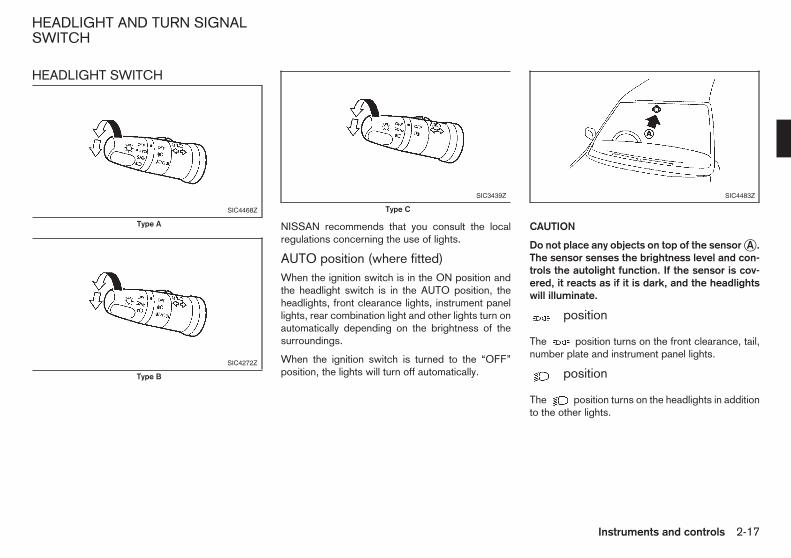
HEADLIGHT SWITCH
NISSAN recommends that you consult the localregulations concerning the use of lights.
AUTO position (where fitted)When the ignition switch is in the ON position andthe headlight switch is in the AUTO position, theheadlights, front clearance lights, instrument panellights, rear combination light and other lights turn onautomatically depending on the brightness of thesurroundings.
When the ignition switch is turned to the “OFF”position, the lights will turn off automatically.
CAUTION
Do not place any objects on top of the sensor jA .The sensor senses the brightness level and con-trols the autolight function. If the sensor is cov-ered, it reacts as if it is dark, and the headlightswill illuminate.
m position
The position turns on the front clearance, tail,number plate and instrument panel lights.
m position
The position turns on the headlights in additionto the other lights.
SIC4468Z
Type A
SIC4272Z
Type B
SIC3439Z
Type C
SIC4483Z
HEADLIGHT AND TURN SIGNALSWITCH
Instruments and controls 2-17

Headlight beamTo turn on the high beam, push the lever towardsthe front position j1 .
To turn off the high beam, return the lever to theneutral position j2 .
To flash the headlights, pull the lever towards therearmost position j3 . The headlights can be flashedeven when the headlights are not on.
Daytime light system (where fitted)Even if the headlight switch is off, the daytime lightswill come on after starting the engine. However, youcannot change low beam to high beam when thelight switch is off.
When the light switch is turned to the position,the headlight low beam will turn off.
HEADLIGHT AIMING CONTROL
Manual typeThe headlight aiming control operates when the ig-nition switch is in the ON position and the headlightis on to allow the headlight axis to be adjusted ac-cording to the driving condition.
When driving with no heavy load/luggage or drivingon a flat road, select the normal position “0”.
If the number of occupants and load/luggage in thevehicle changes, the headlight axis may becomehigher than normal.
If the vehicle is travelling on a hilly road, the head-lights may directly shine on the rearview and outsidemirrors of a vehicle ahead or the windscreen of anoncoming vehicle, which may obscure other drivers’vision.
To adjust to the proper aiming height, turn the switchaccordingly. The higher the number, designated onthe switch, the lower the headlight axis.
SIC3969Z
SIC2275Z
2-18 Instruments and controls

Select the switch position by referring to the following samples.
Model without rear seats (Van):
Model with second row seats (Wagon):
Switchposition
Number of front seatoccupants
Number of rear seatoccupants
Weight of load in the luggage compart-ment
0Driver only 0
No load
2Approximately 634 kg (1,398 lb)
When towing a trailer
Switchposition
Number of front seatoccupants
Number of secondrow seat occupants
Weight of load in the luggagecompartment
0Driver only
0No load
1 23
2 Approximately 259 kg (571 lb)
3Driver only 0 Approximately 475 kg (1,047 lb)
When towing a trailer
Instruments and controls 2-19
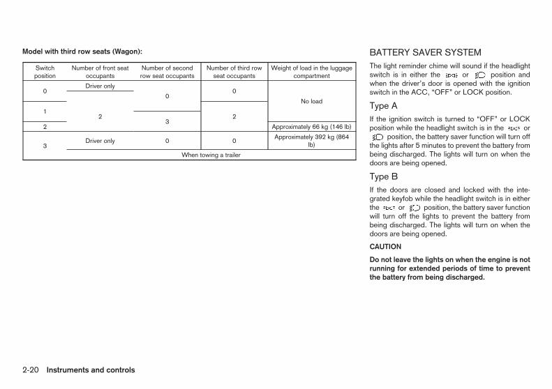
Model with third row seats (Wagon): BATTERY SAVER SYSTEMThe light reminder chime will sound if the headlightswitch is in either the or position andwhen the driver’s door is opened with the ignitionswitch in the ACC, “OFF” or LOCK position.
Type AIf the ignition switch is turned to “OFF” or LOCKposition while the headlight switch is in the or
position, the battery saver function will turn offthe lights after 5 minutes to prevent the battery frombeing discharged. The lights will turn on when thedoors are being opened.
Type BIf the doors are closed and locked with the inte-grated keyfob while the headlight switch is in eitherthe or position, the battery saver functionwill turn off the lights to prevent the battery frombeing discharged. The lights will turn on when thedoors are being opened.
CAUTION
Do not leave the lights on when the engine is notrunning for extended periods of time to preventthe battery from being discharged.
Switchposition
Number of front seatoccupants
Number of secondrow seat occupants
Number of third rowseat occupants
Weight of load in the luggagecompartment
0Driver only
0
No load0
122
32 Approximately 66 kg (146 lb)
3Driver only 0 0
Approximately 392 kg (864lb)
When towing a trailer
2-20 Instruments and controls

TURN SIGNAL SWITCH
CAUTION
The turn signal switch will not be cancelled auto-matically if the steering wheel turning angle doesnot exceed the preset amount. After the turn orlane change, make sure that the turn signalswitch is returned to its original position.
Turn signalTo turn on the turn signals, move the lever up j1 ordown j2 to the point where the lever latches. Whenthe turn is completed, the turn signal cancels auto-matically.
Lane change signalTo turn on the lane change signals, move the leverup j1 or down j2 to the point where the light be-gins to flash.
To cancel the flashing, move the lever to the oppo-site direction.
FRONT FOG LIGHTS (where fitted)
To turn on the front fog lights, turn the headlightswitch to the or position, then turn thefog light switch to the position j1 .
To turn the fog lights off, turn the switch to the“OFF” position.
When the headlight switch is in the AUTO position:
Turning the fog light switch to the or
position will turn on the headlights, fog lights andthe other lights while the ignition switch is in the ONposition or the engine is running.
REAR FOG LIGHTThe rear fog light should be used only when visibilityis seriously reduced [generally, to less than 100 m(328 ft)].
Type ATo turn the rear fog light on, turn the headlight switchto the or position, then turn the switch tothe position j2 . The switch returns to the
position automatically, and the rear fog lightwill illuminate with the front fog lights. Make sure the
indicator light on the instrument panel illumi-nates.
To turn the rear fog light off, turn the fog light switchto the position again. Make sure the indi-cator on the instrument panel turns off.
To turn both the front and rear fog lights off, turn thefog light switch to the “OFF” position.
When the headlight switch is in the AUTO position:
Turning the fog light switch to the orposition will turn on the headlights, fog lights andthe other lights while the ignition switch is in the ONposition or the engine is running.
Type BTo turn the rear fog light on, turn the headlight switchto the or position, then turn the switch tothe position j2 . The switch returns to the
SIC3970Z SIC3971AZ
Type A
SIC3217Z
Type B
FOG LIGHT SWITCH
Instruments and controls 2-21
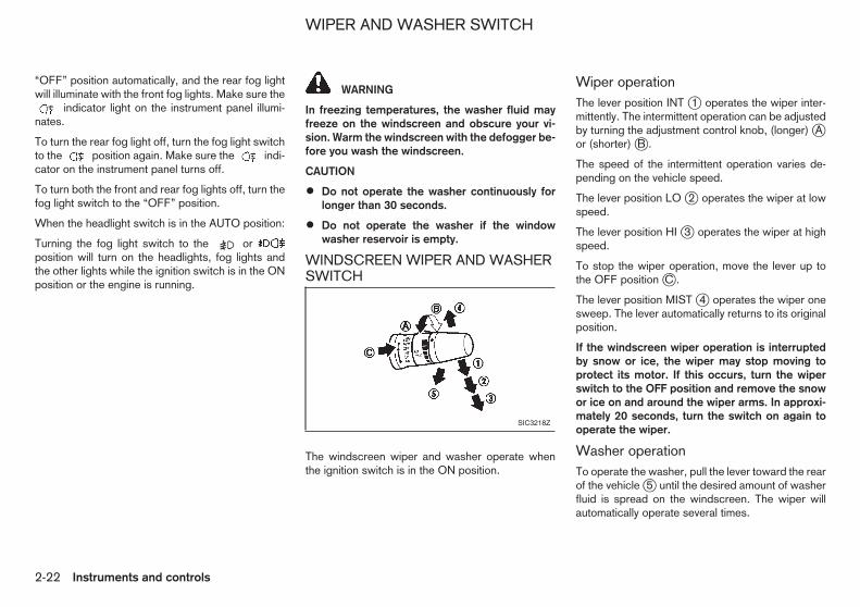
“OFF” position automatically, and the rear fog lightwill illuminate with the front fog lights. Make sure the
indicator light on the instrument panel illumi-nates.
To turn the rear fog light off, turn the fog light switchto the position again. Make sure the indi-cator on the instrument panel turns off.
To turn both the front and rear fog lights off, turn thefog light switch to the “OFF” position.
When the headlight switch is in the AUTO position:
Turning the fog light switch to the orposition will turn on the headlights, fog lights andthe other lights while the ignition switch is in the ONposition or the engine is running.
WARNING
In freezing temperatures, the washer fluid mayfreeze on the windscreen and obscure your vi-sion. Warm the windscreen with the defogger be-fore you wash the windscreen.
CAUTION
• Do not operate the washer continuously forlonger than 30 seconds.
• Do not operate the washer if the windowwasher reservoir is empty.
WINDSCREEN WIPER AND WASHERSWITCH
The windscreen wiper and washer operate whenthe ignition switch is in the ON position.
Wiper operationThe lever position INT j1 operates the wiper inter-mittently. The intermittent operation can be adjustedby turning the adjustment control knob, (longer) jAor (shorter) jB .
The speed of the intermittent operation varies de-pending on the vehicle speed.
The lever position LO j2 operates the wiper at lowspeed.
The lever position HI j3 operates the wiper at highspeed.
To stop the wiper operation, move the lever up tothe OFF position jC .
The lever position MIST j4 operates the wiper onesweep. The lever automatically returns to its originalposition.
If the windscreen wiper operation is interruptedby snow or ice, the wiper may stop moving toprotect its motor. If this occurs, turn the wiperswitch to the OFF position and remove the snowor ice on and around the wiper arms. In approxi-mately 20 seconds, turn the switch on again tooperate the wiper.
Washer operationTo operate the washer, pull the lever toward the rearof the vehicle j5 until the desired amount of washerfluid is spread on the windscreen. The wiper willautomatically operate several times.
SIC3218Z
WIPER AND WASHER SWITCH
2-22 Instruments and controls

Wiper drip wipe system:
The wiper will also operate once about 3 secondsafter the washer and wiper are operated. This op-eration is to wipe washer fluid that has dripped onthe windscreen.
RAIN-SENSING AUTO WIPERSYSTEM (where fitted)
The rain-sensing auto wiper system can automati-cally turn on the wipers and adjust the wiper speeddepending on the rainfall and the vehicle speed byusing the rain sensor located on the upper part ofthe windscreen.
To set the rain-sensing auto wiper system, push thelever down to the AUTO position j1 . The wiper willsweep once while the ignition switch is in the ONposition.
The rain sensor sensitivity level can be adjusted byturning the knob toward the front j2 (High) or to-ward the rear j3 (Low).
• High — High sensitive operation
• Low — Low sensitive operation
To turn the rain-sensing auto wiper system off, pushup the lever to the OFF position, or pull down thelever to the “ ” (LO) or “ ” (HI) position.
CAUTION
Do not touch the rain sensor and around it whenthe wiper switch is in the AUTO position and theignition switch is in the ON position. The wipersmay operate unexpectedly and cause to an injuryor a wiper damage.
• The rain-sensing auto wipers are intended foruse during rain. If the switch is left in the AUTOposition, the wipers may operate unexpect-edly when dirt, fingerprints, oil film or insectsare stuck on or around the sensor. The wipersmay also operate when exhaust gas or mois-ture affect the rain sensor.
• When the windscreen glass is coated with wa-ter repellent, the speed of the rain-sensingauto wipers may be higher even though theamount of the rainfall is small.
• Be sure to turn off the rain-sensing auto wipersystem when you use a car wash.
• The rain-sensing auto wipers may not operateif rain does not hit the rain sensor even if it israining.
REAR WINDOW WIPER ANDWASHER SWITCH (where fitted)
The rear window wiper and washer operates whenthe ignition switch is in the ON position.
Wiper operationThe switch position j1 operates the wiper intermit-tently.
The switch position j2 operates the wiper at lowspeed.
If the rear window wiper operation is interruptedby snow or ice, the wiper may stop moving toprotect its motor. If this occurs, turn the wiperswitch to the OFF position and remove the snowor ice on and around the wiper arms. In approxi-mately 1 minute, turn the switch on again to op-erate the wiper.
SIC4469Z
SIC3565Z
Instruments and controls 2-23

Reverse synchronisation function:
When the windscreen wiper switch is on, movingthe shift lever to the R (Reverse) position will oper-ate the rear window wiper and washer. The rearwindow wiper will be operated once every 7 sec-onds while the above conditions are kept.
Washer operationTo operate the washer, push the lever toward thefront of the vehicle j3 until the desired amount ofwasher fluid is spread on the windscreen. The wiperwill automatically operate several times.
Wiper drip wipe system:
The wiper will also operate once about 3 secondsafter the washer and wiper are operated. This op-eration is to wipe washer fluid that has dripped onthe rear window.
The defogger switch operates when the ignitionswitch is in the ON position.
The defogger is used to reduce the moisture, fog orfrost on the rear window and outside door mirrorsurface (where fitted with the defogger) to improvethe rear view.
When the defogger switch is pushed, the indicatorlight jA illuminates and the defogger operates forapproximately 15 minutes. After the preset time haspassed, the defogger will turn off automatically.
To turn off manually, push the defogger switch again.
CAUTION
• When operating the defogger continuously,be sure to start the engine. Otherwise, it maycause the battery to discharge.
• When cleaning the inner side of the window,be careful not to scratch or damage the elec-trical conductors on the surface of the win-dow.
The hazard indicator flasher switch operates regard-less of the ignition switch position except when thebattery is discharged.
The hazard indicator flasher is used to warn otherdrivers when you have to stop or park under emer-gency conditions.
When the hazard indicator flasher switch is pushed,all turn signal lights will flash. To turn off the hazardindicator flasher, push the hazard indicator flasherswitch again.
SIC1986AZ SIC2475Z
DEFOGGER SWITCH(where fitted)
HAZARD INDICATOR FLASHERSWITCH
2-24 Instruments and controls

The horn switch operates regardless of the ignitionswitch position except when the battery isdischarged.
When the horn switch is pushed and held, the hornwill sound. Releasing the horn switch will cease thehorn sound.
MANUAL WINDOWS (where fitted)The windows can be opened or closed by turningthe hand crank on each door.
SLIDING WINDOWS (where fitted)
To open the sliding window, squeeze the knob j1and slide the window open j2 toward the front ofthe vehicle.
To close, completely close the window until there isa locking sound.
POWER WINDOWS (where fitted)
WARNING
• Make sure that all passengers have theirhands, etc. inside the vehicle before operat-ing the power windows.
• Never leave children or adults who would nor-mally require the support of others alone in
the vehicle. They could unknowingly activateswitches or controls and inadvertentlybecome involved in an accident.
The power windows operate when the ignitionswitch is in the ON position.
To open a window, push down the power windowswitch.
To close a window, pull up the power windowswitch.SIC4220Z
SIC4202Z
SIC4200Z
HORN WINDOWS
Instruments and controls 2-25
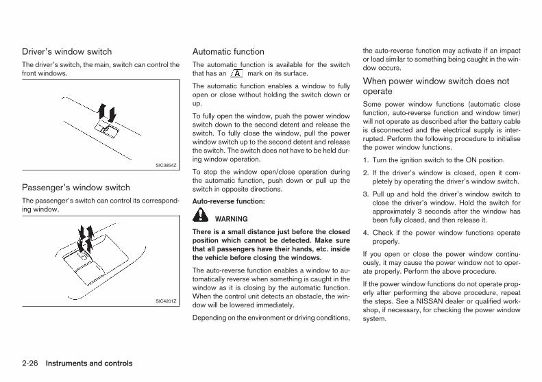
Driver’s window switchThe driver’s switch, the main, switch can control thefront windows.
Passenger’s window switchThe passenger’s switch can control its correspond-ing window.
Automatic functionThe automatic function is available for the switchthat has an mark on its surface.
The automatic function enables a window to fullyopen or close without holding the switch down orup.
To fully open the window, push the power windowswitch down to the second detent and release theswitch. To fully close the window, pull the powerwindow switch up to the second detent and releasethe switch. The switch does not have to be held dur-ing window operation.
To stop the window open/close operation duringthe automatic function, push down or pull up theswitch in opposite directions.
Auto-reverse function:
WARNING
There is a small distance just before the closedposition which cannot be detected. Make surethat all passengers have their hands, etc. insidethe vehicle before closing the windows.
The auto-reverse function enables a window to au-tomatically reverse when something is caught in thewindow as it is closing by the automatic function.When the control unit detects an obstacle, the win-dow will be lowered immediately.
Depending on the environment or driving conditions,
the auto-reverse function may activate if an impactor load similar to something being caught in the win-dow occurs.
When power window switch does notoperateSome power window functions (automatic closefunction, auto-reverse function and window timer)will not operate as described after the battery cableis disconnected and the electrical supply is inter-rupted. Perform the following procedure to initialisethe power window functions.
1. Turn the ignition switch to the ON position.
2. If the driver’s window is closed, open it com-pletely by operating the driver’s window switch.
3. Pull up and hold the driver’s window switch toclose the driver’s window. Hold the switch forapproximately 3 seconds after the window hasbeen fully closed, and then release it.
4. Check if the power window functions operateproperly.
If you open or close the power window continu-ously, it may cause the power window not to oper-ate properly. Perform the above procedure.
If the power window functions do not operate prop-erly after performing the above procedure, repeatthe steps. See a NISSAN dealer or qualified work-shop, if necessary, for checking the power windowsystem.
SIC3854Z
SIC4201Z
2-26 Instruments and controls

Meter display: The digital clock displays the timewhen the CLOCK mode is selected in the trip com-puter. (See “Trip computer” in the “2. Instrumentsand controls” section for the clock setting.)
Audio display (where fitted): The digital clock (in theaudio unit) displays the time when the ignition switchis in the ACC or ON position and the CLOCK ONmode is selected.
If the battery cable is disconnected, the clock willreset its time and the display mode.
ADJUSTING TIME
Audio display model (where fitted)You can select clock display ON and OFF mode.
When clock is not displayed:
If the clock is not displayed with the ignition switchin the ACC or ON position, you need to select theCLOCK ON mode as follows:
1. Turn the audio unit on by pushing the POWERON/OFF button j1 .
2. Push the MENU button j2 and turn the VOL/MENU dial j3 until “CLOCK” is displayed.
3. Push the ENTER button j4 . (“CLOCK OFF” isdisplayed.)
4. Turn the VOL/MENU dial j3 to turn the clockdisplay mode on. (“CLOCK ON” is displayed.)
5. Push the ENTER button j4 . The hour display willstart flashing.
6. Turn the VOL/MENU dial j3 to adjust the time.
7. Push the ENTER button j4 . The minute displaywill start flashing.
8. Turn the VOL/MENU dial j3 to adjust the time.
9. Push the ENTER button j4 to finish the clockadjustment.
When clock is displayed:
1. Turn the audio unit on by pushing the POWERON/OFF button j1 .
2. Push the MENU button j2 and turn the VOL/MENU dial j3 until “CLOCK” is displayed.
3. Push the ENTER button j4 . (“CLOCK ON” isdisplayed.)
4. Perform steps 5 to 9 above to adjust the time.
The power outlet is for powering electrical accesso-ries.
CAUTION
• The outlet and plug may be hot during or im-mediately after use.
• This power outlet is not designed for use witha cigarette lighter unit.
SIC4245Z
SIC4203Z
Front
SIC4482Z
Second row seat (where fitted)
CLOCK POWER OUTLET
Instruments and controls 2-27
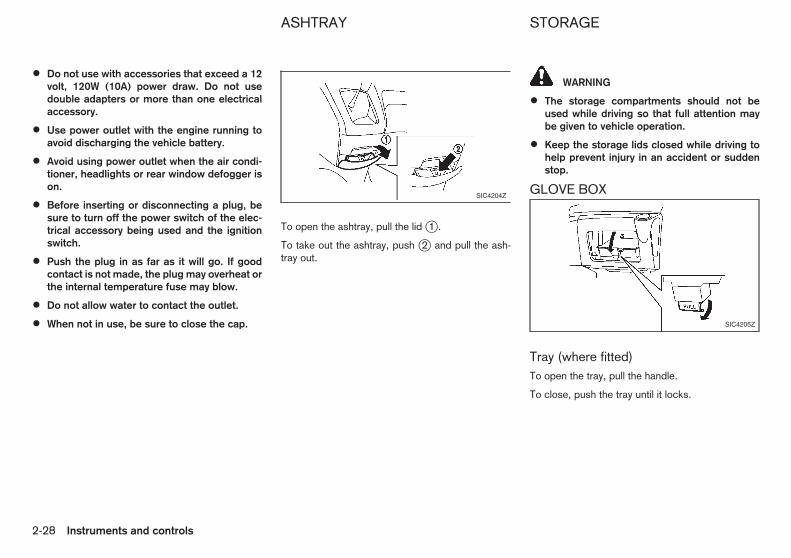
• Do not use with accessories that exceed a 12volt, 120W (10A) power draw. Do not usedouble adapters or more than one electricalaccessory.
• Use power outlet with the engine running toavoid discharging the vehicle battery.
• Avoid using power outlet when the air condi-tioner, headlights or rear window defogger ison.
• Before inserting or disconnecting a plug, besure to turn off the power switch of the elec-trical accessory being used and the ignitionswitch.
• Push the plug in as far as it will go. If goodcontact is not made, the plug may overheat orthe internal temperature fuse may blow.
• Do not allow water to contact the outlet.
• When not in use, be sure to close the cap.
To open the ashtray, pull the lid j1 .
To take out the ashtray, push j2 and pull the ash-tray out.
WARNING
• The storage compartments should not beused while driving so that full attention maybe given to vehicle operation.
• Keep the storage lids closed while driving tohelp prevent injury in an accident or suddenstop.
GLOVE BOX
Tray (where fitted)To open the tray, pull the handle.
To close, push the tray until it locks.
SIC4204Z
SIC4205Z
ASHTRAY STORAGE
2-28 Instruments and controls

CONSOLE BOX
To open the console box lid, push the knob jA upand pull the lid up.
To close, push the lid down until it locks.
UNDER-SEAT TRAY (where fitted)
To open the under-seat tray, pull the tray up and for-ward toward the front of the vehicle.
To close, push in until it stops and pull the tray upuntil it locks.
CAUTION
Do not overfill the tray with materials. They cantouch or strike the seat adjustment lever and mayhinder the operation of the lever, or materialsmay get stuck inside the tray.
BOTTLE HOLDERS (where fitted)
The holders are located in the sliding door pockets.
CAUTION
Do not put an open bottle in the holder, as thedrink may spill when opening or closing the dooror while driving.
CUP HOLDERS
Front and Second row seat
WARNING
The driver must not remove or insert cups intothe cup holder while driving so that full attentionmay be given to vehicle operation.
SIC4206Z
SIC4207Z
SIC4467Z
SIC4208Z
Front
SIC4209Z
Rear
Instruments and controls 2-29

CAUTION
Avoid abrupt starting and braking especiallywhen the cup holder is being used to preventspilling the contents. If the contents are hot, theycould scald you or your passengers.
Third row seat (where fitted)The third row seat cup holder is located on the sideof the third row seat. To use the cup holder, pull itdown jA until it locks.
When storing the cup holder, push it up jB .
CAUTION
• Store the cup holders when entering or leav-ing the third row seat.
• Do not apply an excessive force to the cupholders.
PERSONAL TABLE (where fitted)
The personal table is located on the rear side of thefront seatbacks. To use the table, pull the table upas illustrated jA until it locks.
When storing the table, hold the centre edge of thetable and push the table down jB .
CAUTION
• Do not use the table while driving.
• When the table is not in use, store it to pre-vent an injury or accident.
• Do not apply or place a total load of more than3 kg (7 lb) on the table. This may damage thetable.
HOOKS
WARNING
Do not apply a total load of more than 3 kg (7 lb)to a single hook.
SIC4487Z
Third row seat (where fitted)
SIC4466Z SIC4497Z
2-30 Instruments and controls

CARD HOLDER
A single card (credit-card sized) can be inserted.
CAUTION
Do not insert a card smaller or thinner than theopening. It will become stuck inside and will notbe able to be pulled out.
TICKET HOLDERS
To access the ticket holders, pull the sun visor down.
CAUTION
Do not insert a card thicker than 1 mm (0.04 in)or several tickets to the holders.
UTILITY HOOK
CAUTION
Do not apply a total load of more than 3 kg (6 lb)to the hook.
SIC4211Z SIC4271Z SIC4210Z
Instruments and controls 2-31

LUGGAGE HOOKS
WARNING
• Always make sure that the luggage is prop-erly secured. Use the suitable ropes andhooks.
• Unsecured luggage can become dangerousin an accident or sudden stop.
Type A:
There are 4 - 6 hooks on the floor, depending on themodel.
Type B:
4 hooks are available (stored in the glove box). At-tach the hooks to the rail on the luggage compart-ment.
Push and hold the centre of the hook j1 as shownto attach/remove or move it right or left j2 .
TONNEAU COVER (where fitted)
WARNING
• Never put anything on the tonneau cover, nomatter how small. Any object on it could causean injury in an accident or sudden stop.
• Do not leave the tonneau cover in the vehiclewith it disengaged from the holder.
The tonneau cover keeps the luggage compartmentcontents hidden from the outside.
To use the tonneau cover, pull it out toward the frontj1 and rear j2 of the vehicle, hang both sides onthe hooks j3 .
To remove the tonneau cover, remove it from thehooks and hold until it is retracted.
To stow the tonneau cover, stow the cover and tapthe holder to the upper side.
SIC4222Z
Type A
SIC4223Z
Type B
SIC4224Z
2-32 Instruments and controls

PARTITION (where fitted)
Mesh-typeThe partition can be folded and a long object can beloaded.
CAUTION
Be sure to latch the partition in position afteropening or closing it.
1. Fold the front passenger’s seat by pulling thereclining lever jA .
2. Pull up the lever jB located on the front passen-ger’s seat side to release the partition support.
3. Fold the partition toward the front of the vehicle.
4. Pull down the lever and fit the partition supportinto the hole jC on the front passenger’s seat-back.
1. To block out glare from the front, swing down thesun visor j1 .
2. To block glare from the side, remove the sunvisor from the centre mount and swing it to theside j2 .
SIC4221
SIC2872
SUN VISORS
Instruments and controls 2-33

CAUTION
• Do not leave the light switch on when theengine is not running for extended periods oftime to prevent the battery from being dis-charged.
• Turn off the lights when you leave the vehicle.
ROOM LIGHT
The room light has a three-position switch.
When the switch is in the ON position j2 , the roomlight illuminates.
When the switch is in the “·” (Door) position j1 ,the room light illuminates when a door is opened.
The interior light timer will keep the room light on forapproximately 30 seconds (*1) or 8 seconds (*2)when:
• The key is removed from the ignition switch withthe driver’s door closed.
• The ignition switch is turned to the LOCK posi-tion. (Intelligent Key system equipped model)
• The driver’s door is unlocked without the key inthe ignition switch.
• The driver’s door is opened and then closedwithout the key in the ignition switch.
*1: Model with the Intelligent Key system or remotekeyless entry system
*2: Model without the Intelligent Key system or re-mote keyless entry system
The interior light timer will be cancelled when:
• The driver’s door is locked.
• The ignition switch is turned to the ON position.
When the switch is in the “OFF” position j3 , theroom light does not illuminate, regardless of anycondition.
Battery saver systemIf any door is left open for more than 15 minutes withthe room light switch in the “·” (Door) position j1 ,the room light will automatically turn off.
LUGGAGE COMPARTMENT LIGHT
When the switch is in the ON position j1 , the lightilluminates while the back door is opened.
The interior light timer will keep the luggage com-partment light illuminated for approximately 30 sec-onds (*1) or 8 seconds (*2) when:
• The key is removed from the ignition switch withthe driver’s door closed.
• The ignition switch is turned to the LOCK posi-tion (Intelligent Key system equipped model).
• The driver’s door is unlocked without the key inthe ignition switch.
• The driver’s door is opened and then closedwithout the key in the ignition switch.
*1: Model with the Intelligent Key system or remotekeyless entry system
*2: Model without the Intelligent Key system or re-mote keyless entry system
SIC2489Z
SIC3110AZ
INTERIOR LIGHTS
2-34 Instruments and controls

The interior light timer will be cancelled when:
• The driver’s door is locked.
• The ignition switch is turned to the ON position.
When the switch is in the “OFF” position j2 , thelight does not illuminate, regardless of the condition.
Battery saver systemIf any door is left open for more than 15 minutes withthe luggage compartment light switch in the ONposition j1 , the luggage compartment light will au-tomatically turn off.
Instruments and controls 2-35

NOTE
2-36 Instruments and controls

3 Pre-driving checks and adjustmentsPre-driving checks and adjustments
Keys ........................................................................ 3-2NISSAN Anti-Theft System (NATS*) key ............. 3-2Intelligent Key (where fitted)................................ 3-3
Door locks ............................................................... 3-4Super Lock System (where fitted)....................... 3-4Front door .......................................................... 3-5Sliding door........................................................ 3-6
Remote keyless entry system (where fitted).............. 3-8Using remote keyless entry system ..................... 3-8
Intelligent Key system (where fitted) ......................... 3-10Operating range ................................................. 3-11Using Intelligent Key system................................ 3-12Using remote keyless entry function .................... 3-13Warning lights and audible reminders ................. 3-15
Security system ....................................................... 3-18NISSAN Anti-Theft System (NATS)..................... 3-18
Bonnet..................................................................... 3-19
Opening bonnet.................................................. 3-19Closing bonnet ................................................... 3-19
Back door................................................................ 3-20Locking or unlocking back door .......................... 3-20Tailgate .............................................................. 3-20French doors...................................................... 3-21
Fuel filler lid ............................................................. 3-22Opening fuel filler lid ........................................... 3-22Fuel filler cap...................................................... 3-22
Steering wheel......................................................... 3-23Tilt operation....................................................... 3-23
Mirrors..................................................................... 3-23Inside rearview mirror (where fitted) .................... 3-23Outside rearview mirrors..................................... 3-23
Parking brake .......................................................... 3-24Lever type .......................................................... 3-24
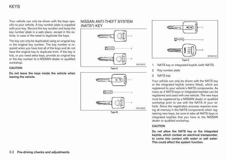
Your vehicle can only be driven with the keys spe-cific to your vehicle. A key number plate is suppliedwith your key. Record the key number and keep thekey number plate in a safe place, except in the ve-hicle, in case of the need to duplicate the keys.
The key can only be duplicated using an original keyor the original key number. The key number is re-quired when you have lost all of the keys and do nothave the original key to duplicate from. If the key islost, or you need extra keys, provide an original keyor the key number to a NISSAN dealer or qualifiedworkshop.
CAUTION
Do not leave the keys inside the vehicle whenleaving the vehicle.
NISSAN ANTI-THEFT SYSTEM(NATS*) KEY
1 NATS key or integrated keyfob (with NATS)
2 Key number plate
3 NATS key
Your vehicle can only be driven with the NATS keyor the integrated keyfob (where fitted), which areregistered to your vehicle’s NATS components. Asmany as 4 NATS keys or integrated keyfobs can beregistered and used with one vehicle. The new keysmust be registered by a NISSAN dealer or qualifiedworkshop prior to use with the NATS of your ve-hicle. Since the registration process requires eras-ing all memory in the NATS components when reg-istering new keys, be sure to take all NATS keys orintegrated keyfobs that you have to the NISSANdealer or qualified workshop.
CAUTION
Do not allow the NATS key or the integratedkeyfob, which contain an electrical transponder,to come into contact with water or salt water.This could affect the system function.
SPA1981Z
Type A
SPA1982Z
Type B
SPA2670Z
Type C
KEYS
3-2 Pre-driving checks and adjustments

*: Immobilizer
INTELLIGENT KEY (where fitted)
1. Intelligent Key (2)
2. Mechanical key (in the Intelligent Key) (2)
3. Key number plate
4. Ignition switch cap
Your vehicle can only be driven with the IntelligentKeys, which are registered to your vehicle’s Intelli-gent Key system components and NISSAN Anti-Theft System (NATS*) components. As many as 4Intelligent Keys can be registered and used withone vehicle. The new keys must be registered by aNISSAN dealer or qualified workshop prior to usewith the Intelligent Key system and NATS of yourvehicle. Since the registration process requireserasing all memory in the Intelligent Key compo-nents when registering new keys, be sure to take allIntelligent Keys that you have to the NISSAN dealeror qualified workshop.
CAUTION
• Do not allow the Intelligent Key, which con-tains electrical components, to come into con-tact with water or salt water. This could affectthe system function.
• Do not drop the Intelligent Key.
• Do not strike the Intelligent Key sharplyagainst another object.
• Do not place the Intelligent Key for an ex-tended period in an area where temperaturesexceed 60°C (140°F).
• Do not attach the Intelligent Key with a keyholder that contains a magnet.
• Do not place the Intelligent Key near equip-ment that produces a magnetic field, such asa TV, audio equipment and personal comput-ers.
*: Immobilizer
SPA2661
Pre-driving checks and adjustments 3-3
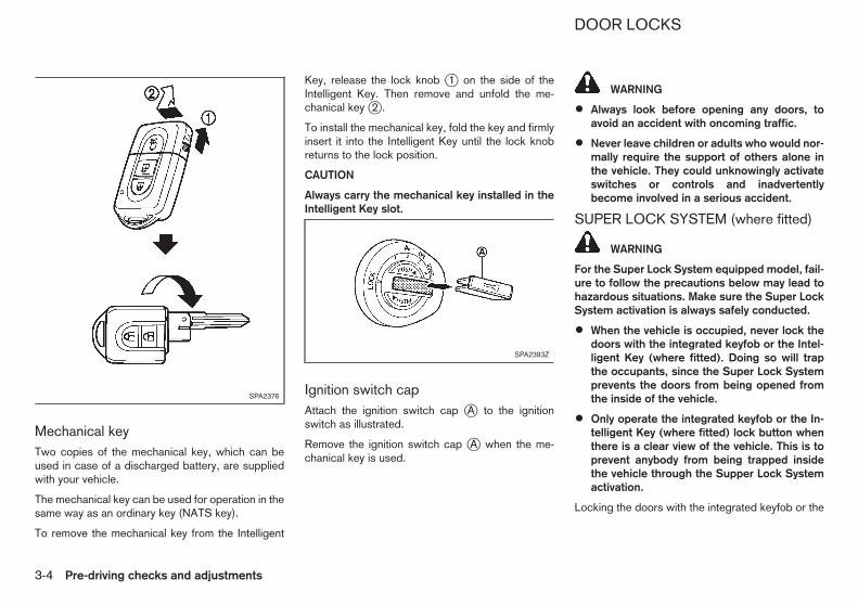
Mechanical keyTwo copies of the mechanical key, which can beused in case of a discharged battery, are suppliedwith your vehicle.
The mechanical key can be used for operation in thesame way as an ordinary key (NATS key).
To remove the mechanical key from the Intelligent
Key, release the lock knob j1 on the side of theIntelligent Key. Then remove and unfold the me-chanical key j2 .
To install the mechanical key, fold the key and firmlyinsert it into the Intelligent Key until the lock knobreturns to the lock position.
CAUTION
Always carry the mechanical key installed in theIntelligent Key slot.
Ignition switch capAttach the ignition switch cap jA to the ignitionswitch as illustrated.
Remove the ignition switch cap jA when the me-chanical key is used.
WARNING
• Always look before opening any doors, toavoid an accident with oncoming traffic.
• Never leave children or adults who would nor-mally require the support of others alone inthe vehicle. They could unknowingly activateswitches or controls and inadvertentlybecome involved in a serious accident.
SUPER LOCK SYSTEM (where fitted)
WARNING
For the Super Lock System equipped model, fail-ure to follow the precautions below may lead tohazardous situations. Make sure the Super LockSystem activation is always safely conducted.
• When the vehicle is occupied, never lock thedoors with the integrated keyfob or the Intel-ligent Key (where fitted). Doing so will trapthe occupants, since the Super Lock Systemprevents the doors from being opened fromthe inside of the vehicle.
• Only operate the integrated keyfob or the In-telligent Key (where fitted) lock button whenthere is a clear view of the vehicle. This is toprevent anybody from being trapped insidethe vehicle through the Supper Lock Systemactivation.
Locking the doors with the integrated keyfob or the
SPA2376
SPA2393Z
DOOR LOCKS
3-4 Pre-driving checks and adjustments

Intelligent Key* (where fitted) will lock all doors in-cluding the back door and activate the Super LockSystem.
This means that none of the doors can be openedfrom the inside in order to prevent theft.
The system will be released when the door is un-locked with the integrated keyfob or Intelligent Key*(where fitted).
The Super Lock System will not activate when thedoors are locked with the power door lock switch orthe key.
*: “LOCK” button or door handle/back doorrequest switch
Emergency situationsIf the Super Lock System is activated due to a traf-fic accident or other unexpected circumstanceswhile you are in the vehicle:
• Turn the ignition switch to the ON position, theSuper Lock System will be released and all thedoors can be unlocked with the power door lockswitch. You can then open the doors.
• Remove the key from the ignition switch and un-lock the door using the integrated keyfob or theIntelligent Key (where fitted). The Super LockSystem will be released and you can open thedoor.
FRONT DOOR
Locking with keyType A:
To lock the door, insert the key to the door key cyl-inder (driver’s or front passenger’s) and turn the keyto the front side of the vehicle j1 . The correspond-ing door will lock.
To unlock the door, turn the key to the rear of thevehicle j2 . The corresponding door will unlock.
Type B:
To lock the door, insert the key to the driver’s doorkey cylinder and turn the key to the front side of thevehicle j1 . All the doors including the back door willlock.
To unlock the door, turn the key to the rear side ofthe vehicle j2 . All the doors including the back doorwill unlock.
Locking with inside lock knobCAUTION
When locking the doors using the inside lockknob, be sure not to leave the key in the vehicle.
Type A:
To lock the door, push the inside lock knob to thelock position j1 , and then close the door.
To unlock the door, push the inside lock knob to theunlock position j2 .
SPA2662Z
SPA2169Z
Type A
Pre-driving checks and adjustments 3-5

Type B:
To unlock and open the door, pull the inside doorhandle as illustrated.
The doors cannot be opened by using the insidedoor handle when the Super Lock System (wherefitted) is activated.
Locking with power door lock switch(where fitted)CAUTION
When locking the doors using the power doorlock switch, be sure not to leave the key in thevehicle.
The power door lock switch is located in the centreof the instrument panel.
Model without Super Lock System:
To lock the doors, push the power door lock switchto the lock position j1 with the driver’s door openand the key removed from the ignition switch, thenclose the door. All doors including the back doorwill lock.
To unlock, push the power door lock switch to theunlock position j2 .
Model with Super Lock System:
To lock the doors, push the power door lock switchto the lock position j1 with the driver’s door openand the key removed from the ignition switch, thenclose the door. All doors including the back doorwill lock.
To unlock, push the power door lock switch to theunlock position j2 .
When the Super Lock System is activated, it is notpossible to operate the power door lock switch.
Lockout protection:
The power door lock switch will not lock the doorsunder the following conditions:
Type A:
• When the key is in the ignition switch and thedriver’s door is open.
• When any door except for the driver’s door isopen.
Type B:
• When the key is in the ignition switch and thedriver’s door is open.
Type C:
• When the key is in the ignition switch and anydoor is open.
SLIDING DOOR
SPA2671Z
Type B
SPA1848ZSPA2693Z
With key cylinder
3-6 Pre-driving checks and adjustments

Model with key cylinderInsert the key to the sliding door key cylinder andturn the key toward the front of the vehicle j1 tolock the sliding door.
Turn the key toward the rear of the vehicle j2 tounlock the sliding door.
Model with integrated keyfob orIntelligent KeyThe sliding door can be locked or unlocked with oneof the following operations.
• Push the “LOCK” or “UNLOCK” but-ton on the integrated keyfob or the IntelligentKey (where fitted). (See “Remote keyless entrysystem (where fitted)” later in this section or “In-telligent Key system (where fitted)” later in thissection.) In selective unlock mode, push the“UNLOCK” button twice to unlock the slidingdoor.
• Push any of the request switches (where fitted).(See “Intelligent Key system (where fitted)” laterin this section.) In selective unlock mode, thedriver’s door handle or back door request switchneeds to be pushed twice to unlock the slidingdoor.
• Push the power door lock switch to the lock orunlock position.
• Lock or unlock the driver’s door lock with thekey or the inside door lock knob.
Opening or closing sliding doorOperate the sliding door by pulling the door handle.
CAUTION
• Always use the door handle to open or closethe sliding door. Do not attempt to open orclose the door by merely placing your hand onthe door edge or door slide roller as this maycause injury.
• When opening the door on a slope, ensurethat it is fully open and that it does not closeby itself.
Locking with inside lock knobTo lock or unlock the sliding door, move the insidelock knob to the LOCK j1 or UNLOCK j2 posi-tion.
To lock from the outside without a key, move thelock knob to the LOCK position j1 , then close thedoor.
SPA2663Z SPA2694Z
SPA2695Z
Pre-driving checks and adjustments 3-7

Child safety sliding door lock(where fitted)The child safety sliding door lock helps prevent slid-ing doors from being opened accidentally, espe-cially when small children are in the vehicle.
When the lever is in the lock position j1 , the childsafety sliding door lock engages and the sliding doorcan only be opened by the outside door handle.
To disengage, move the lever to the unlock positionj2 .
The remote keyless entry system can operate alldoor locks (including the back door) using the inte-grated keyfob. The integrated keyfob can operate ata distance of approximately 1 m (3.3 ft) away fromthe vehicle. The operating distance depends uponthe conditions around the vehicle.
As many as 4 integrated keyfobs can be used withone vehicle. For information about the purchase anduse of additional integrated keyfobs, contact aNISSAN dealer or qualified workshop.
The integrated keyfob will not function under the fol-lowing conditions:
• When the distance between the integrated key-fob and vehicle is more than approximately 1 m(3.3 ft).
• When the integrated keyfob battery isdischarged.
• When the key is in the ignition switch.
CAUTION
• When locking the doors using the integratedkeyfob, be sure not to leave the key in thevehicle.
• Do not allow the integrated keyfob, whichcontains electrical components, to come intocontact with water or salt water. This couldaffect the system function.
• Do not drop the integrated keyfob.
• Do not strike the integrated keyfob sharplyagainst another object.
• Do not place the integrated keyfob for an ex-tended period in an area where temperaturesexceed 60°C (140°F).
If a integrated keyfob is lost or stolen, NISSAN rec-ommends erasing the ID code of that integratedkeyfob from the vehicle. This may prevent the unau-thorised use of the integrated keyfob to unlock thevehicle. For information regarding the erasing pro-cedure, contact a NISSAN dealer or qualified work-shop.
For information regarding the replacement of a bat-tery, see “Battery” in the “8. Maintenance anddo-it-yourself” section.
USING REMOTE KEYLESS ENTRYSYSTEM
j1 “LOCK” button
j2 “UNLOCK” button
SPA2021Z
REMOTE KEYLESS ENTRYSYSTEM (where fitted)
3-8 Pre-driving checks and adjustments

WARNING
For Super Lock System equipped models, failureto follow the precautions below may lead to haz-ardous situations. Make sure the Super Lock Sys-tem activation is always safely conducted.
• When the vehicle is occupied, never lock thedoors with the integrated keyfob. Doing sowill trap the occupants, since the Super LockSystem prevents the doors from being openedfrom the inside of the vehicle.
• Only operate the integrated keyfob lock but-ton when there is a clear view of the vehicle.This is to prevent anybody from being trappedinside the vehicle through the Supper LockSystem activation.
Locking doors1. Remove the key from the ignition switch.
2. Close all doors (including the back door).
3. Push the “LOCK” button j1 on the inte-grated keyfob.
4. All doors will be locked.
5. Operate door handles to confirm that the doorshave been securely locked.
CAUTION
After locking the doors using the integrated key-fob, be sure that the doors have been securelylocked by operating the door handles.
Unlocking doorsAll door unlock mode:
1. Push the “UNLOCK” button on the inte-grated keyfob.
2. All doors (including the back door) will be un-locked.
All doors will be locked automatically unless one ofthe following operations is performed within 2 min-utes after pushing the “UNLOCK” button.
• Opening any door.
• Inserting the key into the ignition switch.
During this 2-minute time period, if the “UNLOCK”button is pushed, all doors will be locked auto-
matically after another 2 minutes.
Selective door unlock mode:
1. Push the “UNLOCK” button j2 on the inte-grated keyfob.
2. The driver’s door will unlock.
3. Push the “UNLOCK” button j2 on the inte-grated keyfob again.
4. All doors (including the back door) will be un-locked.
Selecting door unlock mode:
When you first receive the vehicle, the door unlockmode is set to unlock all the doors with one push ofthe “UNLOCK” button j2 . The door unlockmode can be switched to the selective door unlock
mode, which unlocks the passenger’s doors at thesecond push of the “UNLOCK” button j2 .
To switch to the selective door unlock mode, pushthe “LOCK” and “UNLOCK” buttonssimultaneously for more than 5 seconds.
Perform the same procedure to deactivate the se-lective door unlock mode.
• When the selective unlock mode is set, the haz-ard indicator flashes once.
• When the all door unlock mode is set, the hazardindicator flashes 3 times.
Pre-driving checks and adjustments 3-9

1. Intelligent Key (2)
2. Mechanical key (in the Intelligent Key) (2)
3. Key number plate
4. Ignition switch cap
WARNING
Radio waves could adversely affect electric medi-cal equipment. Those who use a pacemakershould contact the electric medical equipmentmanufacturer for the possible influences beforeuse.
The Intelligent Key system can operate all the doorlocks (including the back door lock) using the inte-grated keyfob function or pushing the request switchon the vehicle without taking the key out from apocket or purse. The operating environment and/orconditions may affect the Intelligent Key system op-eration.
Be sure to read the following before using the Intel-ligent Key system.
CAUTION
• Be sure to carry the Intelligent Key with youwhen operating the vehicle.
• Never leave the Intelligent Key in the vehiclewhen you leave the vehicle.
The Intelligent Key is always communicating withthe vehicle as it receives radio waves. The IntelligentKey system transmits weak radio waves. Environ-mental conditions may interfere with the operationof the Intelligent Key system under the followingoperating conditions.
• When operating near a location where strongradio waves are transmitted, such as a TV tower,power station and broadcasting station.
• When in possession of wireless equipment, suchas a mobile telephone, transceiver, and CB ra-dio.
• When the Intelligent Key is in contact with orcovered by metallic materials.
• When any type of radio wave remote control isused nearby.
• When the Intelligent Key is placed near an elec-tric appliance such as a personal computer.
In such cases, correct the operating conditions be-fore using the Intelligent Key function or use themechanical key.
Although the life of the battery varies depending onthe operating conditions, the battery’s life is approxi-mately 2 years. If the battery is discharged, replaceit with a new one.
Since the Intelligent Key is continuously receivingradio waves, if the key is left near equipment whichtransmits strong radio waves, such as signals froma TV and personal computer, the battery life maybecome shorter.
For information regarding replacement of a battery,see “Battery” in the “8. Maintenance anddo-it-yourself” section.
As many as 4 Intelligent Keys can be used with onevehicle. For information about the purchase and useof additional Intelligent Keys, contact a NISSANdealer or qualified workshop.
SPA2661
INTELLIGENT KEY SYSTEM(where fitted)
3-10 Pre-driving checks and adjustments
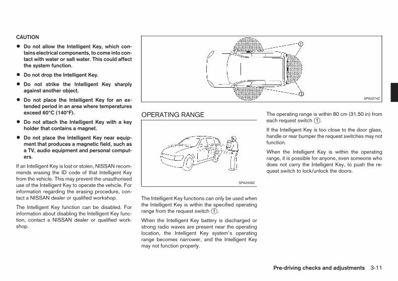
CAUTION
• Do not allow the Intelligent Key, which con-tains electrical components, to come into con-tact with water or salt water. This could affectthe system function.
• Do not drop the Intelligent Key.
• Do not strike the Intelligent Key sharplyagainst another object.
• Do not place the Intelligent Key for an ex-tended period in an area where temperaturesexceed 60°C (140°F).
• Do not attach the Intelligent Key with a keyholder that contains a magnet.
• Do not place the Intelligent Key near equip-ment that produces a magnetic field, such asa TV, audio equipment and personal comput-ers.
If an Intelligent Key is lost or stolen, NISSAN recom-mends erasing the ID code of that Intelligent Keyfrom the vehicle. This may prevent the unauthoriseduse of the Intelligent Key to operate the vehicle. Forinformation regarding the erasing procedure, con-tact a NISSAN dealer or qualified workshop.
The Intelligent Key function can be disabled. Forinformation about disabling the Intelligent Key func-tion, contact a NISSAN dealer or qualified work-shop.
OPERATING RANGE
The Intelligent Key functions can only be used whenthe Intelligent Key is within the specified operatingrange from the request switch j1 .
When the Intelligent Key battery is discharged orstrong radio waves are present near the operatinglocation, the Intelligent Key system’s operatingrange becomes narrower, and the Intelligent Keymay not function properly.
The operating range is within 80 cm (31.50 in) fromeach request switch j1 .
If the Intelligent Key is too close to the door glass,handle or rear bumper the request switches may notfunction.
When the Intelligent Key is within the operatingrange, it is possible for anyone, even someone whodoes not carry the Intelligent Key, to push the re-quest switch to lock/unlock the doors.
SPA2074Z
SPA2408Z
Pre-driving checks and adjustments 3-11

USING INTELLIGENT KEY SYSTEM
The request switch will not function under the fol-lowing conditions:
• When the mechanical key is in the ignition switch.
• When the Intelligent Key is left inside the vehicle(only the unlock function operates).
• When the Intelligent Key is not within the opera-tional range.
• When the doors are open or not closed securely(only the unlock function operates).
• When the Intelligent Key battery is discharged.
Locking doors1. Turn the ignition switch to the LOCK position.
2. Carry the Intelligent Key.
3. Close all doors (including the back door).
4. Push the door handle request switch jA or backdoor request switch jB .
5. All doors will be locked.
6. Operate the door handles to confirm that thedoors have been securely locked.
CAUTION
• After locking the doors using the requestswitch, make sure that the doors have beensecurely locked by operating the doorhandles.
• When locking the doors using the requestswitch, make sure to have the Intelligent Keyin your possession before operating the re-quest switch to prevent the Intelligent Keyfrom being left in the vehicle.
• The request switch is operational only whenthe Intelligent Key has been detected by theIntelligent Key system.
Lockout protection:
To prevent the Intelligent Key from being acciden-tally locked in the vehicle, lockout protection isequipped with the Intelligent Key system.
• When the driver’s side door is open and theIntelligent Key is inside the vehicle (including lug-gage area), the doors cannot be locked usingthe inside lock knob or power door lock switch.
• When the driver’s side door is open, the doorsare locked, and then the Intelligent Key is putinside the vehicle and all the doors are closed;the lock will automatically unlock and the doorbuzzer sounds.
When a person carrying another Intelligent Key,which has been registered to the Intelligent Key sys-tem, enters the vehicle, the lockout protection willbe activated and the lock function by the door handlerequest switch will not operate. To lock, use theremote keyless entry function or the mechanical key.
CAUTION
The lockout protection may not function underthe following conditions:
• When the Intelligent Key is placed on top ofthe instrument panel.
• When the Intelligent Key is placed on the ton-neau cover.
• When the Intelligent Key is placed inside ofthe glove box.
• When the Intelligent Key is placed inside ofthe door pockets.
SPA2664Z
SPA2665Z
3-12 Pre-driving checks and adjustments

• When the Intelligent Key is placed inside themetal box.
The lockout protection may function when theIntelligent Key is outside the vehicle but is tooclose to the vehicle.
Unlocking doorsAll door unlock mode:
1. Carry the Intelligent Key.
2. Push the door handle request switch jA or backdoor request switch jB .
3. All doors (including the back door) will be un-locked.
Selective door unlock mode:
1. Carry the Intelligent Key.
2. Push the door handle request switch jA or backdoor request switch jB .
Driver’s door handle or back door request switch:
Only the corresponding door will be unlocked.
Front passenger’s door handle request switch:
All doors (including the back door) will be un-locked. (Selective door unlock mode is not avail-able.)
3. Push the driver’s door handle request switch jAor back door request switch jB again within 5seconds.
All doors will be unlocked.
If a door handle is pulled while unlocking the doors,
that door may not be unlocked. Returning the doorhandle to its original position will unlock the door. Ifthe door does not unlock, after returning the doorhandle, push the door handle request switch to un-lock the door.
All doors will be locked automatically unless one ofthe following operations is performed within 2 min-utes after pushing the request switch while the doorsare locked.
• Opening any door or back door.
• Pushing in the ignition switch.
• Inserting the mechanical key into the ignitionswitch.
During this 2-minute time period, if the “UNLOCK”button on the Intelligent Key is pushed, all
doors will be locked automatically after another 2minutes.
Selecting door unlock mode:
When you first receive the vehicle, the door unlockmode is set to unlock all the doors with one push ofthe door handle request switch jA or back doorrequest switch jB . The door unlock mode can beswitched to the selective door unlock mode.
To switch to the selective door unlock mode, per-form the following procedure.
Push the “LOCK” and “UNLOCK” but-tons on the Intelligent Key simultaneously for morethan 10 seconds. Within 3 seconds, push the driv-er’s door handle request switch.
Perform the same procedure to deactivate the se-lective door unlock mode.
USING REMOTE KEYLESS ENTRYFUNCTION
j1 “LOCK” button
j2 “UNLOCK” button
WARNING
For Super Lock System equipped models, failureto follow the precautions below may lead to haz-ardous situations. Make sure the Super Lock Sys-tem activation is always safely conducted.
• When the vehicle is occupied, never lock thedoors with the Intelligent Key. Doing so willtrap the occupants, since the Super Lock Sys-tem prevents the doors from being openedfrom the inside of the vehicle.
• Only operate the Intelligent Key lock buttonwhen there is a clear view of the vehicle. This
SPA2380AZ
Pre-driving checks and adjustments 3-13

is to prevent anybody from being trapped in-side the vehicle through the Supper Lock Sys-tem activation.
The remote keyless entry function can operate alldoor locks (including the back door lock) using theremote keyless function of the Intelligent Key. Theremote keyless function can operate at a distance of1 m (3.3 ft) away from the vehicle. The operatingdistance depends upon the conditions around thevehicle.
The remote keyless entry function will not functionunder the following conditions:
• When the mechanical key is in the ignition switch.
• When the Intelligent Key is not within the opera-tional range.
• When the doors are open or not closed securely.(Only the unlock function operates.)
• When the Intelligent Key battery is discharged.
CAUTION
When locking the doors using the Intelligent Key,be sure not to leave the key in the vehicle.
Locking doors1. Turn the ignition switch to the LOCK position.
2. Close all doors (including the back door).
3. Push the “LOCK” button j1 on the Intelli-gent Key.
4. All doors will be locked.
5. Operate the door handles to confirm that thedoors have been securely locked.
CAUTION
After locking the doors using the Intelligent Key,be sure that the doors have been securely lockedby operating the door handles.
Unlocking doorsAll door unlock mode:
1. Push the “UNLOCK” button j2 on the In-telligent Key.
2. All doors (including the back door) will be un-locked.
Selective door unlock mode:
1. Push the “UNLOCK” button j2 on the In-telligent Key.
2. The driver’s door will be unlocked.
3. Push the “UNLOCK” button on the Intelli-gent Key again.
4. All doors (including the back door) will be un-locked.
All doors will be locked automatically unless one ofthe following operations is performed within 2 min-utes after pushing the “UNLOCK” button on theIntelligent Key while the doors are locked.
• Opening any door.
• Pushing in the ignition switch.
• Inserting the mechanical key into the ignitionswitch.
During this 2-minute time period, if the “UNLOCK”button on the Intelligent Key is pushed, all
doors will be locked automatically after another 2minutes.
Selecting door unlock mode:
When you first receive the vehicle, the door unlockmode is set to unlock all the doors with one push ofthe “UNLOCK” button j2 . The door unlockmode can be switched to the selective door unlockmode.
To switch to the selective door unlock mode, per-form the following procedure.
Push the “LOCK” and “UNLOCK” but-tons on the Intelligent Key simultaneously for morethan 10 seconds. Within 3 seconds, push the driv-er’s door handle request switch.
Perform the same procedure to deactivate the se-lective door unlock mode.
3-14 Pre-driving checks and adjustments

WARNING LIGHTS AND AUDIBLEREMINDERS
j1 Intelligent Key system warning light
j2 Intelligent Key lock warning light
j3 NO KEY warning
j4 Key battery discharge indicator
j5 LOCK warning
The Intelligent Key system is equipped with a func-tion that is designed to minimise improper opera-tions and to help prevent the vehicle from being sto-len. The warning buzzer sounds and the warningilluminates when improper operations are detected.
CAUTION
When the buzzer sounds and the warning lightilluminates, be sure to check both the vehicleand the Intelligent Key.
For additional information, see “Warning/indicatorlights and audible reminders” in the “2. Instruments
and controls” section and “Vehicle informationdisplay” in the “2. Instruments and controls” section.
SPA2666Z
Pre-driving checks and adjustments 3-15

Troubleshooting guide
Warnings What to check What to do
The outside buzzer sounds shortcontinuous beeps when operatingthe request switch.
Has the Intelligent Key been left inside of the vehicleor luggage area?
Take the Intelligent Key from inside the vehicle or luggage areaand securely close all the doors.Push the request switch while holding the Intelligent Key.
Has the ignition switch been returned to the LOCKposition?
Return the ignition switch to the LOCK position and securelyclose all the doors.Push the request switch while holding the Intelligent Key.
Are the doors closed completely before pushing therequest switch?
Close all the doors securely.Push the request switch while holding the Intelligent Key.
Is the mechanical key inserted into the ignitionswitch?
Remove the mechanical key from the ignition switch.
The outside buzzer sounds shortcontinuous beeps and the Intel-ligent Key lock warning light blinksin red when closing the driver’sdoor.
Has the ignition switch returned to the LOCK posi-tion?
Return the ignition switch to the LOCK position and securelyclose all the doors.Push the door handle request switch while holding the IntelligentKey.
The outside buzzer sounds shortcontinuous beeps and the Intel-ligent Key system warning lightblinks in red.
Has the Intelligent Key been brought outside thevehicle?
Check the location of the Intelligent Key.The Intelligent Key must be carried by the driver when operatingthe vehicle.
The inside buzzer sounds two shortbeeps and the Intelligent Key lockwarning light blinks in red.
Has the ignition switch returned to the LOCK posi-tion?
Return the ignition switch to the LOCK position.
The inside buzzer sounds shortbeeps for 5 seconds when openingthe driver’s door.
Has the ignition switch returned to the LOCK posi-tion?
Return the ignition switch to the LOCK position.
Is the mechanical key inserted into the ignitionswitch?
Remove the mechanical key from the ignition switch.
3-16 Pre-driving checks and adjustments

Warnings What to check What to do
The Intelligent Key system warninglight blinks in green.
Is the Intelligent Key battery good?Replace the Intelligent Key battery with a new one. (See“Battery” in the “8. Maintenance and do-it-yourself” section.)
The Intelligent Key system warninglight illuminates in red when push-ing the ignition switch.
Are you carrying the Intelligent Key?Carry the Intelligent Key. If the warning light stays on in red,replace the Intelligent Key battery with a new one. (See “Battery”in the “8. Maintenance and do-it-yourself” section.)
Pre-driving checks and adjustments 3-17

Your vehicle is equipped with the NISSAN Anti-theftSystem (NATS)*.
(* immobilizer)
NISSAN ANTI-THEFT SYSTEM (NATS)The NISSAN Anti-Theft System (NATS) will not al-low the engine to start without the use of the regis-tered NATS key, integrated keyfob or Intelligent Key.
If the engine does not start using the registered key,it may be due to interference caused by:
• Another NATS key, integrated keyfob or Intelli-gent Key.
• Automated toll road device.
• Automated payment device.
• Other devices that transmit similar signals.
Start the engine using the following procedure:
1. Remove any items that may be causing the inter-ference away from the key.
2. Leave the ignition switch in the ON position forapproximately 5 seconds.
3. Turn the ignition switch to the “OFF” or LOCKposition, and wait approximately 10 seconds.
4. Repeat steps 2 and 3 again.
5. Start the engine.
6. Repeat the steps above until all possible interfer-ences are eliminated.
If this procedure allows the engine to start, NISSAN
recommends placing the registered key separatefrom other devices to avoid interference.
Security indicator lightThe security indicator light is located on the meterpanel. It indicates the status of NATS.
The light operates whenever the ignition switch is inthe LOCK, “OFF” or ACC position. The securityindicator light indicates that the security systems onthe vehicle are operational.
If NATS is malfunctioning, this light will remain onwhile the ignition switch is in the ON position.
If the light remains on and/or the engine doesnot start, contact a NISSAN dealer or qualifiedworkshop for NATS service as soon as possible.Be sure to bring all keys that you have when vis-iting a NISSAN dealer or qualified workshop forservice.
For Right-Hand Drive (RHD) model:
If NATS is malfunctioning, the security indicator light
will illuminate when the ignition switch is in the ONposition. However, if the security indicator light turnsoff after 15 minutes, you can start the engine once.See a NISSAN dealer or qualified workshop forNATS service as soon as possible.
SIC2045Z
SECURITY SYSTEM
3-18 Pre-driving checks and adjustments

WARNING
• The bonnet must be closed and latched se-curely before driving. Failure to do so couldcause the bonnet to fly open and result in anaccident.
• Never open the bonnet if steam or smoke iscoming from the engine compartment toavoid injury.
OPENING BONNET1. Pull the bonnet lock release handle j1 located
below the instrument panel until the bonnetsprings up.
2. Locate the lever j2 in between the bonnet andgrille and pull the lever up with your fingertips.
3. Raise the bonnet j3 .
4. Remove the support rod j4 and insert it into theslot j5 .
Hold the coated parts jA when removing or re-setting the support rod. Avoid direct contact withthe metal parts, as they may be hot immediatelyafter the engine has been stopped.
CLOSING BONNET1. Reset the support rod to its original position.
2. Slowly move the bonnet down to latch the lock.Push the bonnet down to lock the bonnet se-curely into place.
SPA2667Z
BONNET
Pre-driving checks and adjustments 3-19

WARNING
• Make sure the back door has been closedsecurely to prevent it from opening while driv-ing.
• Do not drive with the back door open. Thiscould allow dangerous exhaust gases to bedrawn into the vehicle.
LOCKING OR UNLOCKING BACKDOOR
Model with key cylinderInsert the key to the back door key cylinder and turnthe key clockwise j1 to lock the back door.
Turn the key anticlockwise j2 to unlock the backdoor.
Model with integrated keyfob orIntelligent KeyThe back door can be locked or unlocked with oneof the following operations.
• Push the “LOCK” or “UNLOCK” but-ton on the integrated keyfob or the IntelligentKey (where fitted). (See “Remote keyless entrysystem (where fitted)” earlier in this section or“Intelligent Key system (where fitted)” earlier inthis section.) In selective unlock mode, push the“UNLOCK” button twice to unlock the backdoor.
• Push any of the request switches (where fitted).(See “Intelligent Key system (where fitted)” ear-lier in this section.) In selective unlock mode, thedriver’s door handle request switch needs to bepushed twice to unlock the back door.
• Push the power door lock switch to the lock orunlock position.
• Lock or unlock the driver’s door lock with thekey or the inside door lock knob.
TAILGATE
Opening back doorPull the back door opener handle j1 and lift up theback door to fully open.
To close the back door, pull down until it securelylocks.
SPA2696Z
With key cylinder
SPA2669Z
BACK DOOR
3-20 Pre-driving checks and adjustments

FRENCH DOORS
The right-side back door cannot be opened whenthe left-side back door is closed.
Opening back door from outside1. Pull the back door opener handle j1 to open the
left-side back door.
2. To open the right-side back door, pull the leverj2 located on the lower side of it.
3. To fully open the back door (180-degrees), pullthe lever j3 located on the inside of each backdoor. The back doors are not designed to belatched in their fully open positions.
Park the vehicle in a safe and level place. Makesure that the area is clear of obstacles and thereis enough clearance around the back doors.
CAUTION
• Always look before fully opening the backdoor(s), to avoid an accident with oncomingtraffic or pedestrians.
• When closing the back doors, be sure to closethe right-side door before closing the left-sidedoor.
Opening back door from insideTo open the back door from the inside of the ve-hicle, pull the inside handle on the left-side backdoor.
SPA2697Z
SPA2698Z
SPA2699Z SPA2700Z
Pre-driving checks and adjustments 3-21
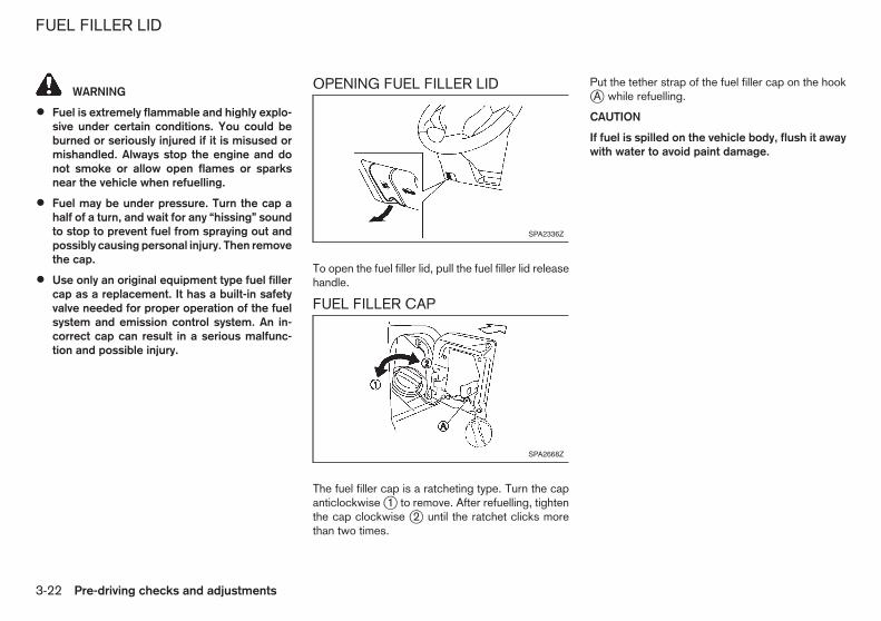
WARNING
• Fuel is extremely flammable and highly explo-sive under certain conditions. You could beburned or seriously injured if it is misused ormishandled. Always stop the engine and donot smoke or allow open flames or sparksnear the vehicle when refuelling.
• Fuel may be under pressure. Turn the cap ahalf of a turn, and wait for any “hissing” soundto stop to prevent fuel from spraying out andpossibly causing personal injury. Then removethe cap.
• Use only an original equipment type fuel fillercap as a replacement. It has a built-in safetyvalve needed for proper operation of the fuelsystem and emission control system. An in-correct cap can result in a serious malfunc-tion and possible injury.
OPENING FUEL FILLER LID
To open the fuel filler lid, pull the fuel filler lid releasehandle.
FUEL FILLER CAP
The fuel filler cap is a ratcheting type. Turn the capanticlockwise j1 to remove. After refuelling, tightenthe cap clockwise j2 until the ratchet clicks morethan two times.
Put the tether strap of the fuel filler cap on the hookjA while refuelling.
CAUTION
If fuel is spilled on the vehicle body, flush it awaywith water to avoid paint damage.
SPA2336Z
SPA2668Z
FUEL FILLER LID
3-22 Pre-driving checks and adjustments

WARNING
Never adjust the steering wheel while driving sothat full attention may be given to vehicle opera-tion.
TILT OPERATION
Pull the lock lever up j1 and adjust the steeringwheel up or down j2 until the desired position isachieved.
Push the lock lever down j3 firmly to lock the steer-ing wheel in place.
WARNING
Adjust the position of all mirrors before driving.Do not adjust the mirror positions while drivingso that full attention may be given to vehicle op-eration.
INSIDE REARVIEW MIRROR(where fitted)
While holding the inside rearview mirror, adjust themirror angles until the desired position is achieved.
OUTSIDE REARVIEW MIRRORS
WARNING
• Never touch the outside rearview mirrorswhile they are in motion. Doing so may pinchyour fingers or damage the mirror.
• Never drive the vehicle with the outside rear-view mirrors folded. This reduces rear viewvisibility and may lead to an accident.
• Objects viewed in the outside mirror arecloser than they appear.
• The picture dimensions and distance in theoutside mirrors are not real.
AdjustingRemote control type:
The outside rearview mirror remote control operateswhen the ignition switch is in the ACC or ON posi-tion.
1. Move the switch to select the right j1 or left j2mirror.
2. Adjust each mirror by pushing the switch untilthe desired position is achieved j2 .
SPA1527Z
SPA2447Z
SPA2214Z
STEERING WHEEL MIRRORS
Pre-driving checks and adjustments 3-23

Manual control type:
The outside mirror can be moved in any direction fora better rear view.
Defogging (where fitted)The outside rearview mirrors will be heated whenthe rear window defogger switch is operated.
FoldingManual control type:
Fold the outside rearview mirror by pushing it to-ward the rear of the vehicle.
WARNING
• Never drive the vehicle with the parking brakeapplied. The brake will overheat and fail tooperate and will lead to an accident.
• Never release the parking brake from outsidethe vehicle. If the vehicle moves, it will beimpossible to push the footbrake pedal andwill lead to an accident.
• Never use the gearshift in place of the park-ing brake. When parking, be sure the parkingbrake is fully applied.
• Never leave children or adults who would nor-mally require the support of others alone inyour vehicle. They could unknowingly releasethe parking brake and inadvertently becomeinvolved in a serious accident.
LEVER TYPE
To apply the parking brake, pull the parking brakelever up j1 .
SPA2242Z
SPA0701ZSPA2110Z
PARKING BRAKE
3-24 Pre-driving checks and adjustments

To release the parking brake, firmly depress andhold the footbrake pedal. Pull up the parking brakelever slightly, push the button j2 and lower the levercompletely j3 .
Before driving, be sure that the brake warning lighthas turned off.
Pre-driving checks and adjustments 3-25

NOTE
3-26 Pre-driving checks and adjustments

4 Display screen, heater and air conditioner,and audio systemDisplay screen, heater and air conditioner,and audio system
Safety precautions ................................................... 4-2Rear view monitor (where fitted)............................... 4-2
How to read the displayed lines .......................... 4-2Operating tips..................................................... 4-3
Vents....................................................................... 4-4Centre vents....................................................... 4-4Side vents .......................................................... 4-4Rear vents .......................................................... 4-4
Heater and air conditioner........................................ 4-4
Manual air conditioner......................................... 4-5Rear cooler (where fitted) ................................... 4-7Servicing air conditioner ..................................... 4-7
Audio system (where fitted)...................................... 4-8Audio operation precautions ............................... 4-8Antenna.............................................................. 4-9CD Player/LW-MW-FM radio ............................. 4-10
Car phone or CB radio ............................................ 4-16

WARNING
• Do not adjust the heater and air conditionercontrols or audio controls while driving so thatfull attention may be given to vehicle opera-tion.
• If you noticed any foreign objects entering thesystem hardware, spilled liquid on the sys-tem, or noticed smoke or fumes coming outfrom the system, or any other unusual opera-tion is observed, stop using the system imme-diately and contact the nearest NISSAN dealeror qualified workshop. Ignoring such condi-tions may lead to an accident, fire or electricshock.
• Do not disassemble or modify this system. Ifyou do, it may lead to an accident, fire, orelectric shock.
• Park the vehicle in a safe location and applythe parking brake to view images on the frontcentre display screen using devicesconnected to the auxiliary input jacks.
CAUTION
Do not use the system when the engine is notrunning for extended periods of time to preventbattery discharge.
When the shift lever is moved into the R (Reverse)position, the monitor display shows view to the rearof the vehicle.
The system is designed as an aid to the driver indetecting large stationary objects to help avoid dam-aging the vehicle. The system will not detect smallobjects below the bumper and may not detect ob-jects close to the bumper or on the ground.
WARNING
• The rear view camera is a convenience but itis not a substitute for proper reversing. Al-ways turn and check that it is safe to do sobefore reversing. Always reverse slowly.
• Objects viewed in the rear view monitor differfrom actual distance because a wide-anglelens is used.
• Objects viewed in the rear view monitor ap-pear visually opposite, just like ones viewedin the inside and outside rearview mirrors.
• Make sure that the back door is securelyclosed when reversing.
• Underneath the bumper and the corner areasof the bumper cannot be viewed on the rearview monitor because of its monitoring rangelimitation.
• Do not put anything on the rear view camera.The rear view camera is installed above thenumber plate.
• When washing the vehicle with high-pressurewater, be sure not to spray it around the cam-era. Otherwise, water may enter the cameraunit causing water condensation on the lens,a malfunction, fire or an electric shock.
• Do not strike the camera. It is a precision in-strument. Otherwise, it may malfunction orcause damage resulting in a fire or an electricshock.
CAUTION
There is a plastic cover over the camera. Do notscratch the cover when cleaning dirt or snow fromthe cover.
HOW TO READ THE DISPLAYEDLINES
WARNING
• Use the displayed lines as a reference. Thelines are highly affected by the number of oc-cupants, fuel level, vehicle position, road con-
SAA0889Z
SAFETY PRECAUTIONS REAR VIEW MONITOR(where fitted)
4-2 Display screen, heater and air conditioner, and audio system

dition and road grade. Always check with youreyes directly around the vehicle while revers-ing.
• The distance guide line and the vehicle widthline should be used as a reference only whenthe vehicle is on a level paved surface. Thedistance viewed on the monitor is for refer-ence only and may be different than the ac-tual distance between the vehicle and dis-played objects.
• When reversing the vehicle up a hill, objectsviewed in the monitor are further than theyappear. When reversing the vehicle down ahill, objects viewed in the monitor are closerthan they appear. Use the inside mirror orglance over your shoulder to properly judgedistances to other objects.
Guiding lines which indicate the vehicle width anddistances to objects with reference to the bumperline jA are displayed on the monitor.
They are indicated as reference distances to ob-jects. Displayed lines indicate distances 0.5 m (red)j1 , 1 m (yellow) j2 , 2 m (green) j3 and 3 m (green)j4 [1.5 feet (red), 3 feet (yellow), 7 feet (green) and10 feet (green)] from the lower part of the bumperline jA .
OPERATING TIPS
• When the shift lever is shifted to R (Reverse), themonitor screen automatically changes to the rearview monitor mode. However, the radio can beheard.
• It may take some time until the rear view monitoror the normal screen is displayed after the shiftlever has been shifted to R (Reverse) from an-other position or to another position from R (Re-verse). Objects may be distorted momentarilyuntil the rear view monitor screen is displayedcompletely.
• When the temperature is extremely high or low,the screen may not clearly display objects. Thisis not a malfunction.
• When strong light directly enters the camera,objects may not be displayed clearly. This is nota malfunction.
• Vertical lines may be seen in objects on thescreen. This is due to strong reflected light fromthe bumper. This is not a malfunction.
• The screen may flicker under fluorescent light.This is not a malfunction.
• The colours of objects on the rear view monitormay differ somewhat from those of the actualobject.
• Objects on the monitor may not be clear in adark place or at night. This is not a malfunction.
• If dirt, rain or snow attaches to the camera, therear view monitor may not clearly display ob-jects. Clean the camera.
• Do not use alcohol, benzine or thinner to cleanthe camera. This will cause discolouration. To
clean the camera, wipe with a cloth dampenedwith diluted mild cleaning agent and then wipewith a dry cloth.
• Do not damage the camera as the monitor screenmay be adversely affected.
• Do not use wax on the camera window. Wipe offany wax with a clean cloth dampened with milddetergent diluted with water.
Display screen, heater and air conditioner, and audio system 4-3

CENTRE VENTS
Open/close the vents by moving the control to ei-ther direction.
: This symbol indicates that the vents areclosed. Moving the control to this direc-tion will close the vents.
: This symbol indicates that the vents areopen. Moving the control to this directionwill open the vents.
Adjust the air flow direction of the vents by movingthe centre knob (up/down, left/right) until the de-sired position is achieved.
SIDE VENTS
Open or close the vents, and adjust the air flowdirection of vents as illustrated.
REAR VENTS
Adjust the air flow direction of the vents by movingthe centre knob (up/down, left/right) until the de-sired position is achieved.
WARNING
• The heater and air conditioner operate onlywhen the engine is running.
• Never leave children or adults who would nor-mally require the support of others alone inthe vehicle. Pets should not be left alone ei-ther. They could unknowingly activateswitches or controls and inadvertentlybecome involved in a serious accident andinjure themselves. On hot, sunny days, tem-peratures in a closed vehicle could quicklybecome high enough to cause severe or pos-sibly fatal injuries to people or animals.
• Do not use the recirculation mode for longperiods as it may cause the interior air to be-come stale and the windows to fog up.
• Do not adjust the heating and air conditioningcontrols while driving so that full attention maybe given to vehicle operation.
NOTE
Condensation forms inside the air conditioningunit when the air conditioner is running, and issafely discharged underneath your vehicle.
Traces of water on the ground are therefore nor-mal.
The heater and air conditioner operate when theengine is running. The air blower will operate even ifthe engine is turned off and the ignition switch is inthe ON position.
SAA2383Z SAA2381Z
SAA2382Z
VENTS HEATER AND AIR CONDITIONER
4-4 Display screen, heater and air conditioner, and audio system

MANUAL AIR CONDITIONER1. Air intake lever (Outside air circulation “ ”
/Air recirculation “ ”)
2. Air flow control dial
3. Fan speed control “ ” dial
4. “A/C” (Air Conditioner) button (where fitted)
5. Temperature control dial
To turn off the heater and air conditioner, turn thefan speed control “ ” dial to the “OFF” (0) posi-tion.
ControlsOutside air circulation:
Move the air intake lever to the “ ” position. Theair flow is drawn from outside the vehicle.
Air recirculation:
Move the air intake lever to the “ ” position. Theair flow is circulated inside the vehicle.
Air flow control:
Turn the air flow control dial to change the air flowmode.
— Air flows from the centre and side vents.— Air flows from the centre and side vents
and foot outlets.— Air flows mainly from the foot outlets.— Air flows from the defogger and foot out-
lets.— Air flows mainly from the defogger out-
lets.
Fan speed control:
Turn the fan speed control “ ” dial clockwise toincrease the fan speed.
Turn the fan speed control “ ” dial anticlockwiseto decrease the fan speed.
A/C (Air Conditioner) operation (where fitted):
Push the “A/C” button to turn the air conditioner onor off. When the air conditioner is on, the “A/C” indi-cator light on the button illuminates.
Temperature control:
Turn the temperature control dial to set the desiredtemperature. Turn the dial between the middle andthe right position to select the hot temperature. Turnthe dial between the middle and the left position toselect the cool temperature.
Heater operationHeating:
This mode is used to direct heated air to the footoutlets.
1. Move the air intake lever to the “ ” positionfor normal heating.
2. Turn the air flow control dial to the “ ” posi-tion.
3. Turn the fan speed control “ ” dial to thedesired position.
4. Turn the temperature control dial to the desiredposition between the middle and the hot (right)position.
Ventilation:
This mode directs outside air to the side and centrevents.
1. Move the air intake lever to the “ ” position.
SAA2587Z
Display screen, heater and air conditioner, and audio system 4-5

2. Turn the air flow control dial to the “ ” posi-tion.
3. Turn the fan speed control “ ” dial to thedesired position.
4. Turn the temperature control dial to the desiredposition.
Defrosting or defogging:
This mode directs the air to the defogger outlets todefrost/defog the windows.
1. Move the air intake lever to the “ ” position.
2. Turn the air flow control dial to the “ ” posi-tion.
3. Turn the fan speed control “ ” dial to thedesired position.
4. Turn the temperature control dial to the desiredposition between the middle and the hot (right)position.
• To remove frost from the outside surface of thewindscreen quickly, turn the temperature controldial to the maximum hot position and the fanspeed control “ ” dial to maximum position.
• If it is difficult to defog the windscreen, turn the“A/C” button on (where fitted).
Bi-level heating:
This mode directs cool air from the side and centrevents and warm air from the foot outlets. When thetemperature control dial is turned to the maximumhot or cool position, the air between the vents andthe foot outlets is the same temperature.
1. Move the air intake lever to the “ ” position.
2. Turn the air flow control dial to the “ ” posi-tion.
3. Turn the fan speed control “ ” dial to thedesired position.
4. Turn the temperature control dial to the desiredposition.
Heating and defogging:
This mode heats the interior and defogs the win-dows.
1. Move the air intake lever to the “ ” position.
2. Turn the air flow control dial to the “ ” posi-tion.
3. Turn the fan speed control “ ” dial to thedesired position.
4. Turn the temperature control dial to the maximumhot (right) position.
Air conditioner operation (where fitted)The air conditioner system should be operated forapproximately 10 minutes at least once a month.This helps prevent damage to the air conditionersystem due to the lack of lubrication.
Cooling:
This mode is used to cool and dehumidify the air.
1. Move the air intake lever to the “ ” position.
2. Turn the air flow control dial to the “ ” posi-tion.
3. Turn the fan speed control “ ” dial to thedesired position.
4. Push the “A/C” button on. (The “A/C” indicatorlight will illuminate.)
5. Turn the temperature control dial to the desiredposition between the middle and the cool (left)position.
A visible mist may be seen coming from the vents inhot, humid conditions as the air is cooled rapidly.This does not indicate a malfunction.
Dehumidified heating:
This mode is used to heat and dehumidify the air.
1. Move the air intake lever to the “ ” position.
2. Turn the air flow control dial to the “ ” posi-tion.
3. Turn the fan speed control “ ” dial to thedesired position.
4. Push the “A/C” button on. (The “A/C” indicatorlight will illuminate.)
5. Turn the temperature control dial to the desiredposition between the middle and the hot (right)position.
Dehumidified defogging:
This mode is used to defog the windows and dehu-midify the air.
1. Move the air intake lever to the “ ” position.
2. Turn the air flow control dial to the “ ” posi-tion.
4-6 Display screen, heater and air conditioner, and audio system

3. Turn the fan speed control “ ” dial to thedesired position.
4. Push the “A/C” button on. (The “A/C” indicatorlight will illuminate.)
5. Turn the temperature control dial to the desiredposition.
REAR COOLER (where fitted)
To activate the rear cooler, take the following steps.
1. Start the engine.
2. Operate the front air conditioner.
Rear cooler function operates only when theengine is running and the front air conditioneris operating.
3. Push the rear cooler front switch j1 (located onthe instrument panel) to the ON position. (Theindicator light jA will illuminate.)
4. Turn the rear cooler fan switch j2 (located onthe side of the third row seat) to the desired posi-tion to select the fan speed.
SERVICING AIR CONDITIONER
WARNING
The air conditioner system contains refrigerantunder high pressure. To avoid personal injury,any air conditioner service should be done onlyby an experienced technician with the properequipment.
The air conditioner system in your vehicle is chargedwith a refrigerant designed with the environment inmind.
NISSAN GREEN PROGRAM
This refrigerant will not harm the earth’s ozonelayer. However, it may contribute in a small part toglobal warming.
Special charging equipment and lubricant are re-
quired when servicing your vehicle’s air conditioner.Using improper refrigerants or lubricants will causesevere damage to the air conditioner system. (See“Air conditioner system refrigerant and lubricant” inthe “9. Technical information” section.)
A NISSAN dealer or qualified workshop will be ableto service your environmentally friendly air condi-tioner system.
Air conditioner filter (where fitted)The air conditioner system is equipped with an airconditioner filter which collects dirt, pollen, dust,etc. To make sure the air conditioner heats, defogs,and ventilates efficiently, replace the filter accordingto the specified maintenance intervals listed in aseparate maintenance booklet. To replace the filter,contact a NISSAN dealer or qualified workshop.
The filter should be replaced if the air flow decreasessignificantly or if windows fog up easily when oper-ating the heater or air conditioner.
SAA0908Z
Rear cooler front switch
SAA2384Z
Rear cooler fan switch
Display screen, heater and air conditioner, and audio system 4-7

AUDIO OPERATION PRECAUTIONS
WARNING
Do not adjust the audio system while driving sothat full attention may be given to vehicle opera-tion.
Radio
• Radio reception is affected by station signalstrength, distance from radio transmitter, build-ings, bridges, mountains and other external influ-ences. Intermittent changes in reception qualitynormally are caused by these external influences.
• Using a mobile phone in or near the vehicle mayinfluence radio reception quality.
Compact Disc (CD) player
• During cold weather or rainy days, the playermay malfunction due to the humidity. If this oc-curs, remove the CD from CD player and dehu-midify or ventilate the player completely.
• The player may skip while driving on rough roads.
• The CD player sometimes may not function whenthe passenger compartment temperature is ex-tremely high. Lower the temperature before use.
• Do not expose the CD to direct sunlight.
• CDs that are of poor quality, or are dirty,scratched, covered with fingerprints, or that havepin holes may not work properly.
• The following CDs may not work properly.
– Copy control compact discs (CCCD)
– Recordable compact discs (CD-R)
– Rewritable compact discs (CD-RW)
• Do not use the following CDs as they may causethe CD player to malfunction.
– 8 cm (3.1 in) discs with an adapter
– CDs that are not round
– CDs with a paper label
– CDs that are warped, scratched or have un-usual edges.
SAA0480
AUDIO SYSTEM (where fitted)
4-8 Display screen, heater and air conditioner, and audio system
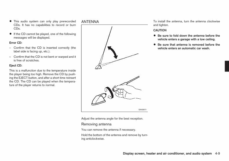
• This audio system can only play prerecordedCDs. It has no capabilities to record or burnCDs.
• If the CD cannot be played, one of the followingmessages will be displayed.
Error CD:
– Confirm that the CD is inserted correctly (thelabel side is facing up, etc.).
– Confirm that the CD is not bent or warped and itis free of scratches.
Eject CD:
This is a malfunction due to the temperature insidethe player being too high. Remove the CD by push-ing the EJECT button, and after a short time reinsertthe CD. The CD can be played when the tempera-ture of the player returns to normal.
ANTENNA
Adjust the antenna angle for the best reception.
Removing antennaYou can remove the antenna if necessary.
Hold the bottom of the antenna and remove by turn-ing anticlockwise.
To install the antenna, turn the antenna clockwiseand tighten.
CAUTION
• Be sure to fold down the antenna before thevehicle enters a garage with a low ceiling.
• Be sure that antenna is removed before thevehicle enters an automatic car wash.
SAA0611
Display screen, heater and air conditioner, and audio system 4-9

1. MUTE button
2. POWER ON/OFF button
3. Sound preference button
4. FM band select button
5. AM band select button
6. Radio memory buttons
7. CD button
8. AUX button
9. TA (Traffic Announcement) button
10. MENU button
11. CD EJECT button
12. SEEK/TRACK button
13. MIX (Mix play) button
14. RPT (Repeat) button
15. VOLUME control/MENU select dial
16. ENTER button
17. AUX jack
18. NEWS button
19. TUNE/SEARCH button
CD PLAYER/LW-MW-FM RADIO
Anti-theft systemBy using a personal 4-digit code known only to thevehicle owner, the possibility of the audio unit beingstolen is effectively reduced, because without thecode, the unit can not be activated. When used nor-mally, the unit is unlocked and accessible in theusual way.
If however, force is used to try and remove the unit,the anti-theft system activates and the unit locks.The only way it can be unlocked is by entering thepersonal code number known only by the owner.This code number cannot be altered and appliesonly to your vehicle. This code number is shown ona radio pass card. Ask your NISSAN dealer or quali-fied workshop for the location of your radio passcard.
SAA2379
4-10 Display screen, heater and air conditioner, and audio system

WARNING
Keep the radio pass card in a safe place andrefrain from keeping it in the vehicle. Contactyour NISSAN dealer or qualified workshop if youlose the radio pass card or forget the code num-ber of your radio.
Unlocking the unit:
CAUTION
Read this section very carefully. It is importantthat the instructions are followed precisely.
If the battery supply to the vehicle is interrupted byaccident for some reason, the unit will lock.
To unlock the unit, proceed as follows:
1. Press the power/volume control knob to turn theunit on.
2. CODE IN is displayed.
3. Input your personal code by pressing the presetbuttons (1 to 4).
4. Press the or button.
5. If the entered code number is correct, the radioturns on. A radio frequency appears on the dis-play.
6. If the entered code is incorrect, the unit becomesinoperable for 10 seconds for the first three at-tempts, then the code input mode is automati-cally set (CODE IN is displayed).
7. If the code is incorrect the fourth time, the unitbecomes inoperable for 60 minutes and ( )
is displayed. After 60 minutes, the code inputmode is automatically set (CODE IN isdisplayed). If the above is repeated 17 times, theunit will lock permanently and you will need tocontact your NISSAN dealer or qualified work-shop.
Audio main operationThe audio system operates when the ignition switchis in the ACC or ON position.
m POWER ON/OFF button:
To turn on the audio system, push the POWERON/OFF button.
• The system will turn on in the mode, (radio orCD) which was used immediately before the sys-tem was turned off.
• If there is no CD loaded, the radio will be turnedon.
To turn off the audio system, push the POWERON/OFF button.
Volume control:
To control the volume, turn the VOLUME controldial.
Turn the VOLUME control dial clockwise to makethe sound louder.
Turn the VOLUME control dial anticlockwise tomake the sound quieter.
Sound preference button:
To enter the audio mode (radio or CD), push thebutton. When no CD is loaded, the audio sys-
tem will automatically switch to the radio mode.
To change the audio settings (BASS, TREBLE,FADER, BALANCE, EQ), push the button orENTER button to select the mode.
BASS → TREBLE → BALANCE → FADER → EQ→ BASS
To adjust each audio setting, turn the MENU/VOLcontrol dial clockwise or anticlockwise.BASS: (−) to decrease / (+) to increaseTREB(LE): (−) to decrease / (+) to increaseBAL(ANCE): (R) to right balance / (L) to left bal-
anceFADE(R): (F) to front fade / (R) to rear fade
EQ (Equalizer):Use this control to change the preset sound modefor CD play.
Turn the MENU/VOL dial clockwise or anticlock-wise. The mode will change as follows:
OFF ⇔ ENHANCE
If the audio settings mode is unchanged for approxi-mately 8 seconds, the audio settings mode will auto-matically return to the normal mode.
Display screen, heater and air conditioner, and audio system 4-11

m Mute button:
Push the button to mute the audio system, andMUTE appears on the display. To cancel the mutemode, use any one of the following options:
– Push the button again.
– Turn the MENU/VOL knob.
– Push the CD, FM or AM button.
– Push the AUX button.
LW-MW-FM radio operationThe audio system operates when the ignition switchis in the ACC or ON position.
FM-AM button:
When the / button is pushed while theaudio system is off, the audio system will turn onand the radio will turn on. When the / but-ton is pushed while CD is already operating, it willautomatically turn off, and the radio will turn on.
To change the radio bands, push the /button until the desired band appears.
/ button:
• For FM
FM 1 → FM 2 → FM T
• For AM
MW → LW → MW
During FM reception, when the button ispushed for longer than 1.5 seconds, stations aresearched for and the 6 strongest stations of the FMT band are stored. The sound is muted until the autostore operation is completed, upon which presetchannel 1 is automatically tuned in.
TUNE button:
When adjusting the broadcasting station frequencymanually, push the or button until thedesired frequency is achieved.
The frequency changes in steps of 100 kHz on theFM band, 9 kHz on the MW band, and 3 kHz on theLW band.
m SEEK button:
When adjusting the broadcasting station frequencyautomatically, push the or button. Whenthe system detects a broadcasting station, it willstop at the station.
j1 j2 j3 j4 j5 j6 Radio memory buttons:
The audio system can store up to 18 FM station fre-quencies (six in each of FM 1, FM 2 and FM T), 6MW and 6 LW station frequencies.
To store the station frequency manually:
1. Tune to the desired broadcasting station fre-quency by using the orbutton.
2. Push and hold a radio memory button j1 - j6until a beep sounds. (The radio mutes when thememory button is pushed.)
3. The channel indicator will display and the radiomute disengages, indicating that the memory isstored properly.
4. Perform steps 1 - 3 for all other memory buttons.
If the battery cable is disconnected, or if the audiofuse blows, the radio memory will be erased. Insuch a case, reset the desired stations.
Radio data system (RDS)Alternative Frequency (AF):
• The AF function operates in the FM (radio) andCD modes.
• When the AF mode is set to ON in the usersetup menu mode, the AF indicator illuminates.
For activation or deactivation details, see “MENUbutton” later in this section.
SAA2380Z
4-12 Display screen, heater and air conditioner, and audio system

• Automatic switching function
This function compares the strengths of the sig-nals of all the stations on the AF list and selectsthe station with the optimum reception condi-tions.
• Programme Information (PI) search
Programme Information (PI) search begins auto-matically if no suitable station is found with theabove automatic switching function. The PIsearch function checks each RDS station withthe same PI code. During this time the sound ismuted and “PI SEARCH” is displayed. The PIsearch operation stops when a suitable station isfound. If no station is found once all the frequen-cies have been searched, the radio returns tothe previous frequency.
• Enhanced Other Network (EON) data update(This function also operates when the AFmode is off.)
When EON data is being received, this enablesautomatic retuning of other preset stations onthe same network. Also, network linked servicescan be used. The EON indicator turns on duringthe reception of RDS EON stations in the FMmode.
RDS functions:
• Programme Service (PS) function (stationname display function)
When an RDS station is tuned in with seek ormanual tuning, the RDS data is received and theProgramme Service (PS) name is displayed.
• Emergency broadcast interrupt function(ALARM INTERRUPTION — EBU SPEC FORINFO)
When the radio receives PTY code 31 (an emer-gency broadcast code), the sound is interrupted,the emergency broadcast is heard, and “PTY31ALARM” is displayed. The volume level at thistime is the same as that for traffic announce-ments. Once the emergency broadcast is fin-ished, the unit immediately returns to the previ-ous source.
• REG (Regional) mode
Some local radio stations are linked together ac-cording to their region because they only offerlimited coverage due to their limited number oftransmitters. If the signal from one station be-comes weak while you are driving around, RDSmode will switch to another local station in theregion with a stronger signal.
When the REG mode is activated in the FM bandand the radio receiver is tuned to a local radiostation, it will keep receiving this radio stationwithout switching to another local station. Foractivation or deactivation details, see “MENUbutton” later in this section.
Traffic Announcement (TA):
• The TA function operates in the FM and CDmodes.
• The TA mode is turned on or off when the TAbutton is pushed.
• The TA mode operates regardless of whetherthe AF mode is on or off.
• “TA ON” is displayed when the TA mode isturned on, and the TA indicator turns on. “TAOFF” is displayed when the TA mode is turnedoff, and the TA indicator turns off.
The following functions operate when the TA modeis on:
• Traffic announcement interrupt function
When a traffic announcement is received, theannouncement is tuned in and the volume in-creases to the set level.
Once the traffic announcement is finished, theunit returns to the source which was set beforethe traffic announcement started, and the vol-ume returns to the previous level. For EON sta-tions, the radio is interrupted by another EONstation with traffic announcements.
The traffic announcement interrupt mode is can-celled if the TA is pushed during a traffic an-nouncement. The TA mode returns to thestandby mode and the audio unit returns to theprevious source.
News mode
When the button is pushed in the FM mode,the news function is activated. “NEWS” is displayedfor 3 seconds and the NEWS indicator appears onthe display.
When the news function is activated, the radio re-ceives a news code from the FM broadcasting news
Display screen, heater and air conditioner, and audio system 4-13

station and the actual playing mode will be inter-rupted. Once the news broadcast is finished, theunit returns to the previous mode.
In some countries or regions, this service is notavailable or the signal is too weak to be received.
1. News standby mode
• The news standby mode can be activated inthe FM or CD mode.
• A news interruption will be announced and“NEWS” will be displayed when the radio de-tects the news code from the tuned station orEON stations. The display will then change tothe PS name of the interrupting station.
• When pushing the button, the newsstandby mode is turned off and the indicatordisappears from the display.
2. News interruption mode
• When the button is pushed during thenews interruption mode, the radio returns tothe previous source. However, the newsstandby mode is kept.
• When the button is pushed during thenews interruption mode, the radio changes tothe CD mode. However, the news standbymode is kept.
If the radio band is changed to the MW orLW, the news standby mode will be turnedoff.
MENU button:
To configure Alternative Frequency, Regional andLanguage settings, perform the following proce-dure:
1) Push and hold the MENU button for at least 1.5seconds.
2) Turn the MENU/VOL dial clockwise or anticlock-wise. The display message will change as fol-lows:
AF ⇔ REG ⇔ LANGUAGE ⇔ AF
• To activate or deactivate the AF and REG mode,briefly push on the ENTER button when AF orREG appears on the display and turn the MENU/VOL dial clockwise or anticlockwise to switchbetween the off or on position. After selection,push the ENTER button to confirm the settings.
– When the AF mode is enabled, the audio unitwill automatically re-tune to a stronger fre-quency if the radio signal becomes weak.
– When the REG mode is enabled, the audiounit will maintain and hold the station which isbroadcasting local (regional) programmes.
• To change the display language, briefly push theENTER button when LANGUAGE appears onthe display then turn the MENU/VOL dial clock-wise or anticlockwise to select the appropriatelanguage setting.
ENGLISH ⇔ DUTCH ⇔ FRENCH ⇔ SPAN-ISH ⇔ GERMAN ⇔ ITALIAN ⇔ PORTU-GUESE ⇔ ENGLISH
After selecting the desired language, push theENTER button to exit the menu.
To configure the SPEED volume and BEEP set-tings, perform the following procedure:
1) Push the MENU button.
2) Turn the MENU/VOL dial clockwise or anticlock-wise. The display message will change as fol-lows:
SPEED VOL ⇔ CLOCK ⇔ BEEP ⇔ SPEEDVOL
• When SPEED VOL appears on the display,briefly push on the ENTER button then turn theMENU/VOL dial clockwise or anticlockwise toadjust the level of the volume.
Adjusting the setting to 0 (zero) turns off thespeed volume feature. Increasing the speed vol-ume setting results in the audio volume increas-ing more rapidly with vehicle speed. Push theENTER button again to save the setting.
• For clock adjustment, see “Clock” in the “2. In-struments and controls” section.
• When BEEP appears on the display, briefly pushthe ENTER button and then turn the MENU/VOLdial clockwise or anticlockwise to switch thebeep sound on or off. Push the ENTER buttonagain to save the setting.
After the desired levels have been set, push theMENU button to exit the menu or wait at least for 10seconds without pressing any buttons.
4-14 Display screen, heater and air conditioner, and audio system

CD player operationThe audio system operates when the ignition switchis in the ACC or ON position.
Loading:
Insert a CD into the slot with the label side facingup. The CD will be guided automatically into the slotand will start playing. If the radio is already playing,it will automatically turn off, and the CD will startplaying.
CAUTION
Do not force the CD into the slot. This could dam-age the player.
After loading the CD, the number of tracks and theplaytime will appear on the display.
CD button:
When the button is pushed while the audiosystem is off and a CD is loaded, the audio systemwill turn on and a CD will start playing automatically.If the radio is already playing, it will automaticallyturn off and the CD will start playing.
FF (Fast Forward), REW(Rewind) button:
When the (fast forward) or (rewind) button is pushedwhile the CD is being played, the CD will play whilefast forwarding or rewinding. When the button isreleased, the CD will return to normal play speed.
m TRACK UP/ DOWN button:
When the button is pushed while a CD isbeing played, the present track will be advancedand move to the next track. Push the buttonseveral times to skip forward tracks. The CD willadvance the number of times the button is pushed.When the last track of the CD is forwarded, the firsttrack will be played.
When the button is pushed while a CD isbeing played, the present track will start over fromthe beginning. Push the button several timesto skip back tracks. The CD will rewind the numberof times the button is pushed. When the first trackof the CD is rewound, the last track will be played.
Repeat button:
Push the button repeatedly to change the playmode as follows:
RPT (REPEAT) TRACK → RPT (REPEAT) ALLRPT TRACK: The CD player plays the current
track continuously.RPT ALL: All the tracks on the CD will be played
in sequential order.
MIX button:
Push the button repeatedly to change the playmode as follows:
MIX DISC → RPT ALL → MIX DISCMIX DISC: All the tracks on the CD will be played
in a random order.RPT ALL: All the tracks on the CD will be played
in sequential order.
m CD EJECT button:
When the button is pushed while a CD isloaded, the CD will be ejected.
When the button is pushed twice, the CD willbe ejected further, and the CD can be removed withease.
If a CD is ejected by pushing the button, andit is not taken out from the loading slot, the CD willautomatically be reloaded to the slot to protect theCD.
SAA2380Z
Display screen, heater and air conditioner, and audio system 4-15

AUX button:
The AUX IN jack is located on the audio unit. TheAUX IN audio input jack accepts any standard ana-log audio input such as from a portable cassettetape/CD player, MP3 player, laptop computers, etc.
Push the button to play a compatible devicewhen it is plugged into the AUX IN jack.
When installing a CB, ham radio or a car phone inyour vehicle, be sure to observe the following cau-tions, otherwise the new equipment may adverselyaffect the Engine Control System and other elec-tronic parts.
CAUTION
• Keep the antenna as far away as possible fromthe Electronic Control Module.
• Keep the antenna wire at least 20 cm (8 in)away from the Engine Control harnesses. Donot route the antenna wire next to any har-nesses.
• Adjust the antenna standing wave ratio as rec-ommended by the manufacturer.
• Connect the ground wire from the radio chas-sis to the body.
• For details, consult a NISSAN dealer or quali-fied workshop.
NOTE
For further information, visit the NISSAN web site:www.nissan-europe.com. Select your countryfrom the list and go to the “SERVICES” menu. Ifnot available on the web site, contact a NISSANdealer or qualified workshop.
CAR PHONE OR CB RADIO
4-16 Display screen, heater and air conditioner, and audio system

5 Starting and drivingStarting and driving
Running-in schedule ................................................ 5-2Before starting engine.............................................. 5-2Precautions when starting and driving ...................... 5-2
Exhaust gas (carbon monoxide) .......................... 5-2Three-way catalyst (petrol engine model) ............ 5-3
Care when driving ................................................... 5-4Engine cold start period...................................... 5-4Loading luggage................................................. 5-4Driving in wet conditions ..................................... 5-4Driving in winter conditions ................................. 5-4
Ignition switch.......................................................... 5-4Intelligent Key system (where fitted) .................... 5-4Manual Transmission (MT) .................................. 5-5Steering lock ...................................................... 5-6Key positions ...................................................... 5-6
Starting engine ........................................................ 5-6Petrol engine ...................................................... 5-6Diesel engine...................................................... 5-7NISSAN Anti-Theft System (NATS)..................... 5-7
Driving vehicle ......................................................... 5-8Driving with Manual Transmission (MT) ............... 5-8
Electronic Stability Programme (ESP) (wherefitted)....................................................................... 5-9
Electronic Stability Programme (ESP) OFFswitch................................................................. 5-10
Parking.................................................................... 5-11Trailer towing........................................................... 5-12
Operating precautions ........................................ 5-12Tyre pressure ..................................................... 5-12Safety chains...................................................... 5-13Trailer brakes...................................................... 5-13Trailer detection (where fitted) ............................ 5-13Coupling device installation................................. 5-13
Electric power steering system ................................ 5-14Brake system........................................................... 5-15
Brake precautions .............................................. 5-15Anti-lock Braking System (ABS).......................... 5-15
Vehicle security........................................................ 5-16Cold weather driving................................................ 5-17
Battery ............................................................... 5-17Engine coolant.................................................... 5-17Tyre equipment................................................... 5-17Special winter equipment.................................... 5-17Corrosion protection........................................... 5-18

During the first 1,600 km (1,000 miles), follow theserecommendations to obtain maximum engine per-formance and ensure the future reliability andeconomy of your new vehicle. Failure to follow theserecommendations may result in shortened enginelife and reduced engine performance.
• Do not drive at a constant speed, either fast orslow, for long periods of time.
• Do not run the engine over 4,000 rpm (HR16DEengine) or 2,500 rpm (K9K engine).
• Do not accelerate at full throttle in any gear.
• Do not start quickly.
• Do not brake hard as much as possible.
• Do not tow a trailer for at least the first 800 km(500 miles).
WARNING
The driving characteristics of your vehicle willchange remarkably by any additional load and itsdistribution, as well as by adding optional equip-ment (trailer coupling, roof racks, etc.). Your driv-ing style and speed must be adjusted accordingto the circumstances. Especially when carryingheavy loads, your speed must be reduced ad-equately.
• Make sure the area around the vehicle is clear.
• Visually inspect tyres for their appearance andcondition. Measure and check the tyre pressurefor proper inflation.
• Check that all windows and lights are clean.
• Adjust the seat and head restraint positions.
• Adjust the inside and outside rearview mirror po-sitions.
• Fasten your seat belt and ask all passengers todo the same.
• Check that all doors are closed.
• Check the operation of the warning lights whenthe ignition switch is turned to the ON position.
• Maintenance items in the “8. Maintenance anddo-it-yourself” section should be checked peri-odically.
WARNING
• Never leave children or adults who would nor-mally require the support of others alone inyour vehicle. Pets should not be left aloneeither. They could unknowingly activateswitches or controls and inadvertentlybecome involved in a serious accident andinjure themselves. On hot, sunny days, tem-peratures in a closed vehicle could quicklybecome high enough to cause severe or pos-sibly fatal illness to people or animals.
• Properly secure all luggage to help prevent itfrom sliding or shifting. Do not place luggagehigher than the seatbacks. In a sudden stopor collision, unsecured luggage could causepersonal injury.
EXHAUST GAS (carbon monoxide)
WARNING
• Do not breathe exhaust gas; it contains co-lourless and odourless carbon monoxide. Car-bon monoxide is dangerous. It can cause un-consciousness or death.
• If you suspect that exhaust fumes are enter-ing the vehicle, drive with all windows fullyopen, and have the vehicle inspected imme-diately.
• Do not run the engine in closed spaces suchas a garage.
RUNNING-IN SCHEDULE BEFORE STARTING ENGINE PRECAUTIONS WHEN STARTINGAND DRIVING
5-2 Starting and driving

• Do not park the vehicle with the engine run-ning for an extended period of time.
• Keep the back door closed while driving, oth-erwise exhaust gas could be drawn into thepassenger compartment. If you must drivewith the back door open, follow these precau-tions:
– Open all the windows.
– Turn the air recirculation mode off and setthe fan speed control to the highest levelto circulate the air.
• If electrical wiring or other cable connectionsmust pass to a trailer through the seal of theback door or the body, follow the manufactur-er’s recommendation to prevent carbon mon-oxide entry into the vehicle.
• If a special body or other equipment is addedfor recreational or other usage, follow themanufacturer’s recommendation to preventcarbon monoxide entry into the vehicle.(Some recreational vehicle appliances suchas stoves, refrigerators, heaters, etc. may alsogenerate carbon monoxide.)
• The exhaust system and body should be in-spected by a qualified mechanic whenever:
– Your vehicle is raised while being serviced.
– You suspect that exhaust fumes are enter-ing into the passenger compartment.
– You notice a change in the sound of theexhaust system.
– You have had an accident involving dam-age to the exhaust system, underbody, orrear of the vehicle.
THREE-WAY CATALYST (petrol enginemodel)
WARNING
• The exhaust gas and the exhaust system arevery hot. Keep people, animals and flammablematerials away from the exhaust system com-ponents.
• Do not stop or park the vehicle over flam-mable materials such as dry grass, wastepa-per or rags. They may ignite and cause a fire.
NISSAN GREEN PROGRAM
The three-way catalyst is an emission control deviceinstalled in the exhaust system. Exhaust gas in thethree-way catalyst is burned at high temperatures tohelp reduce pollutants.
CAUTION
• Do not use leaded petrol. (See “Recom-mended fuel/lubricants and capacities” in the“9. Technical information” section.) Depositsfrom leaded petrol seriously reduce the abil-ity of the three-way catalyst to help reduceexhaust pollutants and/or damage the three-way catalyst.
• Keep your engine tuned up. Malfunctions inthe ignition, fuel injection, or electrical sys-tems may cause overrich fuel to flow into the
three-way catalyst, causing it to overheat. Donot keep driving if the engine misfires, or ifnoticeable loss of performance or other un-usual operating conditions are detected. Havethe vehicle inspected promptly by a NISSANdealer or qualified workshop.
• Avoid driving with an extremely low fuel level.Running out of fuel could cause the engine tomisfire, damaging the three-way catalyst.
• Do not race the engine while warming it up.
• Do not push or tow your vehicle to start theengine.
Starting and driving 5-3

Driving your vehicle to fit the circumstances is es-sential for your safety and comfort. As a driver, youshould be the one who knows best how to drive inthe given circumstances.
ENGINE COLD START PERIODDue to the higher engine speeds, when the engineis cold, extra caution must be exercised when se-lecting a gear during the engine warm-up periodafter starting the engine.
LOADING LUGGAGELoads and their distribution and the attachment ofequipment (coupling devices, roof luggage carriers,etc.) will considerably change the driving character-istics of the vehicle. Your driving style and speedmust be adjusted according to the circumstances.
DRIVING IN WET CONDITIONS
• Avoid accelerating or stopping suddenly.
• Avoid sharp turning or lane changing suddenly.
• Avoid following too close to the vehicle in front.
When water covers the road surface with waterpuddles, small water streams, etc., reduce speed toprevent hydroplaning which can cause skidding andloss of control. Worn tyres will increase this risk.
DRIVING IN WINTER CONDITIONS
• Drive cautiously.
• Avoid accelerating or stopping suddenly.
• Avoid sharp turning or lane changing suddenly.
• Avoid sudden steering.
• Avoid following too close to the vehicle in front.WARNING
Never remove the key or turn the ignition switchto the LOCK position while driving. The steeringwheel will lock and could cause the driver to losecontrol of the vehicle. This could result in seriousvehicle damage or personal injury.
j1 LOCK (PUSH OFF)
j2 LOCK (PUSH ON)
INTELLIGENT KEY SYSTEM(where fitted)The Intelligent Key system can operate the ignitionswitch without taking the key out of your pocket orpurse. The operating environment and/or conditionsmay affect the Intelligent Key system operation.
CAUTION
• Be sure to carry the Intelligent Key with youwhen operating the vehicle.
NSD368
CARE WHEN DRIVING IGNITION SWITCH
5-4 Starting and driving

• Never leave the Intelligent Key inside the ve-hicle when you leave the vehicle.
• If the vehicle battery is discharged, the igni-tion switch cannot be moved from the LOCKposition and if the steering lock is engaged,the steering wheel cannot be moved. Chargethe battery as soon as possible. (See “Jumpstarting” in the “6. In case of emergency” sec-tion.)
Remove the ignition switch cap jA when the me-chanical key is used.
Operating rangeThe Intelligent Key functions can only be used forstarting the engine when the Intelligent Key is withinthe specified operating range j1 .
When the Intelligent Key battery is almostdischarged or strong radio waves are present nearthe operating location, the Intelligent Key system’soperating range becomes narrower and may notfunction properly.
If the Intelligent Key is within the operating range, itis possible for anyone, even someone who does notcarry the Intelligent Key, to turn the ignition switch tostart the engine.
• The luggage area is not included in the operatingrange, but the Intelligent Key may function.
• If the Intelligent Key is placed on the instrumentpanel, inside the glove box or door pocket, theIntelligent Key may not function.
• If the Intelligent Key is placed near the door orwindow outside the vehicle, the Intelligent Keymay function.
MANUAL TRANSMISSION (MT)
The ignition switch includes a device that helps pre-vent accidental removal of the key while driving.
The key can only be removed when the ignitionswitch is in the LOCK position.
The “OFF” position j1 is between the LOCK andACC positions, although it is not marked on the igni-tion switch.
SSD0436Z
SSD0392Z
Without Intelligent Key system
SSD0645Z
With Intelligent Key system
Starting and driving 5-5
Models with Intelligent Key systemThe ignition lock is designed so that the switch canonly be turned to the LOCK position when the PUSHrelease button j2 has been pushed.
• The Intelligent Key lock warning light blinksand the buzzer sounds when the ignition switchis not turned to the LOCK position completelywithout pushing the PUSH release button j2 .For further details regarding the functionality ofthe Intelligent Key lock warning light, see “Intel-ligent Key lock warning light (where fitted)” in the“2. Instruments and controls” section.
• When the mechanical key is being used, the ig-nition PUSH release button has to be pushed inorder to turn the ignition switch to the LOCKposition although the Intelligent Key lock warn-ing light will not blink and the buzzer willnot sound.
STEERING LOCK
To lock steering wheel1. Turn the ignition switch to the LOCK position.
2. Remove the key, if it is inserted in the ignitionswitch.
3. Turn the steering wheel 1/6 of a turn clockwisefrom the straight up position.
To unlock steering wheel1. Insert the key into the ignition switch.
2. Gently turn the ignition switch while rotating thesteering wheel slightly right and left.
KEY POSITIONS
LOCK (0)The ignition key can only be removed at this posi-tion.
The steering lock can only be locked at this position.
Intelligent Key system:PUSH OFF - The steering lock can only be
locked at this position.PUSH ON - The ignition switch will be unlocked
while carrying the Intelligent Key.
OFF (1)The engine is turned off with the steering wheelunlocked.
ACC (2)The electrical accessory power activates without theengine turned on.
ON (3)The ignition system and the electrical accessorypower activate without the engine turned on.
START (4)The engine starter activates and the engine will start.The ignition switch, when released, will automati-cally turn to the ON position.
CAUTION
As soon as the engine has started, release theignition switch immediately.
PETROL ENGINE1. Apply the parking brake.
2. Depress the footbrake pedal.
3. Move the shift lever to the N (Neutral) position,and depress the clutch pedal to the floor whilestarting the engine.
Intelligent Key system: Slowly “PUSH ON” theignition switch and depress the footbrake pedal.When the Intelligent Key system warning light inthe meter illuminates in green, the ignition switchcan be turned.
The Intelligent Key must be carried when op-erating the ignition switch.
When the Intelligent Key lock warning light in themeter blinks in red and the inside warning buzzeremits a short beep, be sure that the shift lever isin the N (Neutral) position and the ignition switchis securely returned to the LOCK position.
4. Crank the engine with your foot off the accelera-tor pedal by turning the ignition switch to theSTART position.
5. Immediately release the ignition switch when theengine starts. If the engine starts, but fails to run,repeat the above procedures.
If the engine is very hard to start in extremely coldor hot weather, depress the accelerator pedaland hold it to help start the engine.
STARTING ENGINE
5-6 Starting and driving

CAUTION
• Do not operate the starter for more than 15seconds at a time. If the engine does not start,turn the ignition switch off and wait 10 sec-onds before cranking the engine again. Oth-erwise, the starter could be damaged.
• If it becomes necessary to start the enginewith a booster battery and jumper cables, theinstructions and cautions contained in the “6.In case of emergency” section should be care-fully followed.
6. Allow the engine to idle for at least 30 secondsafter starting the engine to warm-up. Drive atmoderate speeds for a short distance first, espe-cially in cold weather.
CAUTION
Do not leave the vehicle unattended while theengine is warming up.
DIESEL ENGINE1. Apply the parking brake.
2. Depress the footbrake pedal.
3. Move the shift lever to the N (Neutral) position,and depress the clutch pedal to the floor whilestarting the engine.
Intelligent Key system: Slowly “PUSH ON” theignition switch and depress the footbrake pedal.When the Intelligent Key system warning light inthe meter illuminates in green, the ignition switchcan be turned.
The Intelligent Key must be carried when op-erating the ignition switch.
When the Intelligent Key lock warning light in themeter blinks in red and the inside warning buzzeremits a short beep, be sure that the shift lever isin the N (Neutral) position and the ignition switchis securely returned to the LOCK position.
4. Turn the ignition switch to the ON position andwait until the glow plug indicator light turnsoff.
5. Crank the engine with your foot off the accelera-tor pedal by turning the ignition switch to theSTART position.
6. Immediately release the ignition switch when theengine starts. If the engine starts, but fails to run,repeat the above procedures.
CAUTION
• Do not operate the starter for more than 20seconds at a time. If the engine does not start,turn the ignition switch off and wait 20 sec-onds before cranking the engine again. Oth-erwise, the starter could be damaged.
• If it becomes necessary to start the enginewith a booster battery and jumper cables, theinstructions and cautions contained in the “6.In case of emergency” section should be care-fully followed.
7. Allow the engine to idle for at least 30 secondsafter starting the engine to warm-up. Drive atmoderate speeds for a short distance first, espe-cially in cold weather.
CAUTION
Do not leave the vehicle unattended while theengine is warming up.
NISSAN ANTI-THEFT SYSTEM (NATS)The NISSAN Anti-Theft System (NATS) will not al-low the engine to start without the use of the regis-tered NATS key, integrated keyfob or Intelligent Key.
If the engine does not start using the registered key,it may be due to interference caused by:
• Another NATS key, integrated keyfob or Intelli-gent Key.
• Automated toll road device.
• Automated payment device.
• Other devices that transmit similar signals.
Start the engine using the following procedure:
1. Remove any items that may be causing the inter-ference away from the key.
2. Leave the ignition switch in the ON position forapproximately 5 seconds.
3. Turn the ignition switch to the “OFF” or LOCKposition, and wait approximately 5 seconds.
4. Start the engine.
Starting and driving 5-7

5. Repeat the steps above until all possible interfer-ences are eliminated.
If this procedure allows the engine to start, NISSANrecommends placing the registered key separatefrom other devices to avoid interference.
DRIVING WITH MANUALTRANSMISSION (MT)
WARNING
• Do not downshift abruptly on slippery roads.This may cause a loss of control.
• Do not over-rev the engine when shifting to alower gear. This may cause a loss of vehiclecontrol or engine damage.
CAUTION
• Do not rest your foot on the clutch pedal whiledriving. This may damage the clutch system.
• Fully depress the clutch pedal before shiftingto help prevent transmission damage.
• Stop the vehicle completely before shiftinginto the R (Reverse) position.
• When the vehicle is stopped for a period oftime, for example waiting at stoplights, shiftto the N (Neutral) position and release theclutch pedal with the footbrake pedaldepressed.
Starting vehicle1. After starting the engine, depress the clutch
pedal to the floor and move the shift lever to the“1” (1st) or R (Reverse) position.
2. Slowly depress the accelerator pedal, releasingthe clutch pedal and parking brake at the sametime.
Shifting gearTo change gears, or when upshifting or downshift-ing, fully depress the clutch pedal, shift into the ap-propriate gear, then slowly and smoothly release theclutch pedal.
Start the vehicle in the “1” (1st) position and shift tothe “2” (2nd), “3” (3rd), “4” (4th) and “5” (5th) gearin sequence according to the vehicle speed.
If it is difficult to move the shift lever into the R(Reverse) or “1” (1st) position, shift to the N (Neu-tral) position, and then release the clutch pedal once.Fully depress the clutch pedal again and shift into Ror “1”.
You cannot shift directly from the “5” (5th) positioninto the R (Reverse) position. First shift into the N(Neutral) position, then shift into the R (Reverse)position.
SSD0535Z
DRIVING VEHICLE
5-8 Starting and driving

Upshift indicatorThe manual transmission upshift indicator is locatedin the tachometer and shows the driver the timing toshift into a higher gear by illuminating. The use of theupshift indicator will help you to upshift at a constantengine speed from any gear.
The upshift indicator will illuminate when the enginespeed reaches the set figure while driving.
The engine speed for upshifting can be set in thesetting mode of the vehicle information display. See“Vehicle information display” in the “2. Instrumentsand controls” section.
There may be a slight difference between thetiming of the upshift indicator illumination andthe tachometer indication.
Suggested maximum speed in each gearDownshift to a lower gear if the engine is not run-ning smoothly, or if you need to accelerate.
Do not exceed the maximum suggested speed(shown below) in any gear. For level road driving,use the highest gear suggested for that speed. Al-ways observe posted speed limits, and drive ac-cording to the road conditions which will ensuresafe operation. Do not over-rev the engine whenshifting to a lower gear as it may cause engine dam-age or loss of vehicle control.
HR16DE engine model:km/h (MPH)
1st 43 (27)2nd 79 (49)3rd 117 (73)4th 148 (92)5th — (—)
K9K engine model:km/h (MPH)
1st 32 (20)2nd 59 (37)3rd 91 (57)4th 124 (77)5th — (—)
WARNING
• The Electronic Stability Programme (ESP) sys-tem is designed to help improve driving sta-bility but does not prevent accidents due toabrupt steering operation at high speeds ordue to careless or dangerous driving tech-niques. Reduce vehicle speed and be espe-cially careful when driving and cornering onslippery surfaces and always drive carefully.
• If engine related parts such as a muffler arenot standard equipment or are extremely de-teriorated, the ESP OFF indicator or “SLIP”indicator or both indicator lights may illumi-nate.
• Do not modify the vehicle’s suspension. Ifsuspension parts such as shock absorbers,struts, springs, stabiliser bars and bushingsare not NISSAN-approved or are extremelydeteriorated the ESP system may not operateproperly. This could adversely affect vehiclehandling performance, and the ESP OFF indi-cator or “SLIP” indicator or both indicatorlights may illuminate.
• If brake related parts such as brake pads, ro-tors and callipers are not standard equipmentor are extremely deteriorated, the ESP OFFindicator or “SLIP” indicator or both indicatorlights may illuminate.
• When driving on extremely inclined surfacessuch as higher banked corners, the ESP sys-tem may not operate properly and the ESP
SSD0879Z
ELECTRONIC STABILITYPROGRAMME (ESP) (where fitted)
Starting and driving 5-9

OFF indicator or “SLIP” indicator or both indi-cator lights may illuminate. Do not drive onthese types of roads.
• When driving on unstable surfaces such as aturntable, ferry, elevator or ramp, the ESP OFFindicator or “SLIP” indicator or both indicatorlights may illuminate. This is not a malfunc-tion. Restart the engine after driving onto astable surface.
• If wheels or tyres other than those recom-mended are used, the ESP system may notoperate properly and ESP OFF indicator or“SLIP” indicator or both indicator lights mayilluminate.
• The ESP system is not a substitute for wintertyres or tyre chains on a snow-covered road.
When accelerating or driving on slippery surfaces,the tyres may spin or slide. With the Electronic Sta-bility Programme (ESP) system, sensors detectthese movements and control the braking and en-gine output to help improve vehicle stability.
• When the ESP system is operating, the “SLIP”indicator in the instrument panel blinks.
• If the “SLIP” indicator blinks, the road conditionsare slippery. Be sure to adjust your speed anddriving to these conditions. Be sure to drive care-fully. (See “Slip indicator light (where fitted)” inthe “2. Instruments and controls” section and“Electronic Stability Programme (ESP) off indi-cator light (where fitted)” in the “2. Instrumentsand controls” section.)
• Indicator light
If a malfunction occurs in the system, the “SLIP”and ESP OFF indicator lights illumi-
nate in the instrument panel. As long as theseindicators are illuminated, the ESP system func-tion is cancelled.
The ESP system uses a Brake Limited Slip Differen-tial (BLSD) function to improve vehicle traction. TheBLSD system works when one of the driving wheelsis spinning on a slippery surface. The BLSD systembrakes the spinning wheel, which distributes thedriving power to the other drive wheel. If the vehicleis operated with the ESP system turned off, all ESPsystem functions will be turned off.
The BLSD system and ABS will still operate with theESP system off. If the BLSD system is activated, the“SLIP” indicator light will blink and you may hear aclunk noise and/or feel a pulsation in the brake pedal.This is normal and is not an indication of a malfunc-tion.
While the ESP system is operating, you may feel apulsation in the brake pedal and hear a noise or feela vibration from under the bonnet. This is normaland indicates that the ESP system is working prop-erly.
The ESP system computer has a built-in diagnosticfeature that tests the system each time you start theengine and move the vehicle at a low speed forwardor backward. When the self-test occurs, you mayhear a “clunk” noise and/or feel a pulsation in thefootbrake pedal. This is normal and is not an indica-tion of a malfunction.
ELECTRONIC STABILITYPROGRAMME (ESP) OFF SWITCH
The vehicle should be driven with the ElectronicStability Programme (ESP) system on for most driv-ing conditions.
When the vehicle is stuck in mud or snow, the ESPsystem reduces the engine output to reduce wheelspin. The engine speed will be reduced even if theaccelerator is depressed to the floor. If maximumengine power is needed to free a stuck vehicle, turnthe ESP system off.
To turn off the ESP system, push the ESP OFFswitch located on the lower side of the instrumentpanel. The indicator light will illuminate.
Push the ESP OFF switch again or restart the en-gine to turn on the system.
SIC2257Z
5-10 Starting and driving

WARNING
• Do not stop or park the vehicle over flam-mable materials such as dry grass, waste pa-per or rags. They may ignite and cause a fire.
• Safe parking procedures require that both theparking brake be applied and the shift leverplaced in an appropriate gear. Failure to do socould cause the vehicle to move unexpect-edly or roll away and result in an accident.
• Never leave the engine running while the ve-hicle is unattended.
• Never leave children or adults who would nor-mally require the support of others alone inthe vehicle. Pets should not be left alone ei-ther. They could unknowingly activateswitches or controls and inadvertentlybecome involved in a serious accident andinjure themselves. On hot, sunny days, tem-peratures in a closed vehicle could quicklybecome high enough to cause severe or pos-sibly fatal illness to people and animals.
1. Firmly apply the parking brake.
2. Move the shift lever to the R (Reverse) position.When parking on an uphill grade, move the shiftlever to the “1” (1st) position.
3. To help prevent the vehicle from moving into traf-fic when parked on an incline, it is a good prac-tice to turn the wheels as illustrated.
HEADED DOWNHILL WITH CURB j1
Turn the wheels towards the curb and move thevehicle forward until the curb side wheel gentlytouches the curb. Then apply the parking brake.
HEADED UPHILL WITH CURB j2
Turn the wheels away from the curb and allowthe vehicle to move back until the curb side wheelgently touches the curb. Then apply the parkingbrake.
SSD0488Z
Left-Hand Drive (LHD) model
SSD0489Z
Right-Hand Drive (RHD) model
PARKING
Starting and driving 5-11

HEADED UPHILL OR DOWNHILL, WITHOUTCURB j3
Turn the wheels toward the side of the road sothe vehicle will move away from the centre of theroad if the vehicle moves. Then apply the parkingbrake.
4. Turn the ignition switch to the LOCK positionand remove the key (if inserted).
Your new vehicle was designed to be used primarilyto carry passengers and luggage.
Towing a trailer will place additional loads on yourvehicle’s engine, drive train, steering, braking andother systems. The towing of a trailer will exagger-ate other conditions such as sway caused by cross-winds, rough road surfaces or passing trucks.
Your driving style and speed must be adjusted ac-cording to the circumstances. Before towing atrailer, see a NISSAN dealer or qualified workshopfor an explanation about the proper use of towingequipment.
OPERATING PRECAUTIONS
• Avoid towing a trailer during the running-in pe-riod.
• Before driving, make sure that the lighting sys-tem of the trailer works properly.
• Observe the legal maximum speeds for traileroperation.
Do not exceed 100 km/h (62 MPH).
• Avoid abrupt starts, accelerations and stops.
• Avoid sharp turns and lane changes.
• Always drive your vehicle at a moderate speed.
• Follow the trailer manufacturer’s instructions.
• Choose proper coupling devices (trailer hitch,safety chain, roof carrier, etc.) for your vehicleand trailer. These devices are available from a
NISSAN dealer or qualified workshop where youcan also obtain more detailed information abouttrailer towing.
• Never allow the total trailer load (trailer weightplus its cargo weight) to exceed the maximumset for the vehicle and the coupling device. Seea NISSAN dealer or qualified workshop for moreinformation.
• The trailer must be loaded so that heavy goodsare placed over the axle. The maximum allowablevertical load on the trailer hitch must not be ex-ceeded.
• Have your vehicle serviced more often than atthe intervals specified in a separate maintenancebooklet.
• Trailer towing requires more fuel than under nor-mal circumstances because of a considerableincrease in traction power and resistance.
While towing a trailer, check the engine coolanttemperature indicator to prevent the vehicle fromoverheating.
TYRE PRESSUREWhen towing a trailer, inflate the vehicle tyres to themaximum recommended COLD tyre pressure (forfull loading) indicated on the tyre placard.
Do not tow a trailer when the vehicle is installed witha temporary spare tyre or a compact spare tyre.
TRAILER TOWING
5-12 Starting and driving

SAFETY CHAINSAlways use a suitable chain between the vehicleand trailer. The chain should be crossed and shouldbe attached to the hitch, not to the vehicle bumperor axle. Be sure to leave enough slack in the chainto permit turning corners.
TRAILER BRAKESEnsure that trailer brakes are installed as requiredby local regulations. Also check that all other trailerequipment conforms to local regulations.
Always block the wheels on both the vehicle andtrailer when parking. Apply the hand brake on thetrailer where fitted. Parking on a steep slope is notrecommended.
If parking on a steep slope is unavoidable, place theshift lever in an appropriate gear, and turn the frontwheels towards the curb.
TRAILER DETECTION (where fitted)When towing a trailer with a Genuine NISSAN C2tow bar electrical kit and the turn signal switch isused, the electrical system of the vehicle will detectthe additional electrical load of the trailer lighting. Asa result, there will be an additional turn indicator inthe meter dedicated to the trailer.
COUPLING DEVICE INSTALLATIONNISSAN recommends that the coupling device fortrailer towing be installed under the following condi-tions:
• Maximum permissible vertical load on the cou-pling device: 736 N (75 kg, 165 lb)
• The coupling device, mounting points and instal-lation parts on your vehicle: as shown as an ex-ample in the illustration.
• Rear overhang of coupling device: jA 956 mm(37.6 in)
Follow all of the coupling device manufacturer’s in-structions for installation and use.
SSD0882
Starting and driving 5-13

When removing the spare tyre from the vehicle withthe trailer coupling device installed, it is necessaryto unload the vehicle. (See “Flat tyre” in the “6. Incase of emergency” section for spare tyre removal.)
WARNING
If the engine is not running or is turned off whiledriving, the power assist for the steering will notwork. The steering will be much harder to oper-ate.
When the electric power steering warning lightilluminates with the engine running, the powerassist for the steering will cease operation. Youwill still have control of the vehicle but the steer-ing will be harder to operate.
The electric power steering system is designed toprovide power assist while driving to operate thesteering wheel with light force.
When the steering wheel is operated repeatedly orcontinuously while parking or driving at a very lowspeed, the power assist for the steering wheel willbe reduced. This is to prevent overheating of theelectric power steering system and protect it fromgetting damaged. While the power assist is re-duced, steering wheel operation will become heavy.When the temperature of the electric power steer-ing system goes down, the power assist level willreturn to normal. Avoid repeating such steeringwheel operations that could cause the electricpower steering system to overheat.
You may hear a fricative sound when the steeringwheel is operated quickly. However, this is not amalfunction.
If the electric power steering warning light illu-minates while the engine is running, it may indicatethe electric power steering system is not functioning
properly and may need servicing. Have the electricpower steering system checked by a NISSAN dealeror qualified workshop. (See “Electric power steer-ing warning light” in the “2. Instruments andcontrols” section.)
When the electric power steering warning light illu-minates with the engine running, the power assistfor the steering will cease operation. You will stillhave control of the vehicle. However, greater steer-ing effort is needed, especially in sharp turns and atlow speeds.
ELECTRIC POWER STEERINGSYSTEM
5-14 Starting and driving

The brake system has two separate hydraulic cir-cuits. If one circuit malfunctions, you will still havebraking ability at two wheels.
BRAKE PRECAUTIONS
Vacuum assisted brakesThe brake booster aids braking by using enginevacuum. If the engine stops, you can stop the ve-hicle by depressing the footbrake pedal. However,greater foot pressure on the footbrake pedal will berequired to stop the vehicle. The stopping distancewill be longer.
If the engine is not running or is turned off while driv-ing, the power assisted brakes will not function.Braking will be harder.
WARNING
Do not coast with the engine stopped.
Using brakesAvoid resting your foot on the footbrake pedal whiledriving. This will overheat the brakes, wear out thebrake linings/pads faster, and increase fuel con-sumption.
To help reduce brake wear and to prevent the brakesfrom overheating, reduce speed and downshift to alower gear before going down a slope or long grade.Overheated brakes may reduce braking perfor-mance and could result in loss of vehicle control.
While driving on a slippery surface, be careful when
braking, accelerating or downshifting. Abrupt brak-ing or acceleration could cause the wheels to skidand result in an accident.
Wet brakesWhen the vehicle is washed or driven through wa-ter, the brakes may get wet. As a result, your brak-ing distance will be longer and the vehicle may pullto one side during braking.
To dry the brakes, drive the vehicle at a safe speedwhile lightly depressing the brake pedal to heat upthe brakes. Do this until the brakes return to normal.Avoid driving the vehicle at high speeds until thebrakes function correctly.
Driving uphillWhen starting on a steep grade, it is sometimes dif-ficult to operate both the brake and clutch (for MTmodel). Apply the parking brake to hold the vehicle.Do not slip the clutch. When ready to start, slowlyrelease the parking brake while depressing the ac-celerator pedal and releasing the clutch pedal.
Driving downhillThe engine braking action is effective for controllingthe vehicle while descending hills. The shift levershould be placed in the lower speed position priorto descending.
ANTI-LOCK BRAKING SYSTEM (ABS)
WARNING
• The Anti-lock Braking System (ABS) is a so-phisticated device, but it cannot prevent acci-dents resulting from careless or dangerousdriving techniques. It can help maintain ve-hicle control during braking on slippery sur-faces. Remember that stopping distances onslippery surfaces will be longer than on nor-mal surfaces even with ABS. Stopping dis-tances may also be longer on rough, gravel orsnow covered roads, or if you are using tyrechains. Always maintain a safe distance fromthe vehicle in front of you. Ultimately, thedriver is responsible for safety.
• Tyre type and condition may also affect brak-ing effectiveness.
• When replacing tyres, install the specifiedsize of tyres on all four wheels.
• When installing a spare tyre, make surethat it is the proper size and type as speci-fied on the tyre placard. (See “Tyreplacard” in the “9. Technical information”section.)
• For detailed information, see “Tyres andwheels” in the “8. Maintenance anddo-it-yourself” section.
The Anti-lock Braking System (ABS) controls thebrakes so the wheels do not lock during hard brak-ing or when braking on slippery surfaces. The sys-
BRAKE SYSTEM
Starting and driving 5-15

tem detects the rotation speed at each wheel andvaries the brake fluid pressure to prevent each wheelfrom locking and sliding. By preventing each wheelfrom locking, the system helps the driver maintainsteering control and helps to minimise swerving andspinning on slippery surfaces.
Using systemDepress the brake pedal and hold it down. Depressthe brake pedal with firm steady pressure, but donot pump the brakes. The ABS will operate to pre-vent the wheels from locking up. Steer the vehicle toavoid obstacles.
WARNING
Do not pump the brake pedal. Doing so may re-sult in increased stopping distances.
Self-test featureThe ABS includes electronic sensors, electricpumps, hydraulic solenoids and a computer. Thecomputer has a built-in diagnostic feature that teststhe system each time you start the engine and movethe vehicle at a low speed in forward or reverse.When the self-test occurs, you may hear a “clunk”noise and/or feel a pulsation in the brake pedal. Thisis normal and does not indicate a malfunction. If thecomputer senses a malfunction, it switches the ABSoff and illuminates the ABS warning light on theinstrument panel. The brake system then operatesnormally, but without anti-lock assistance.
If the ABS warning light illuminates during the self-
test or while driving, have the vehicle checked by aNISSAN dealer or qualified workshop.
Normal operationThe ABS operates at speeds above 5 to 10 km/h (3to 6 MPH). The speed varies according to road con-ditions.
When the ABS senses that one or more wheels areclose to locking up, the actuator rapidly applies andreleases hydraulic pressure. This action is similar topumping the brakes very quickly. You may feel apulsation in the brake pedal and hear a noise fromunder the bonnet or feel a vibration from the actua-tor when it is operating. This is normal and indicatesthat the ABS is operating properly. However, thepulsation may indicate that road conditions are haz-ardous and extra care is required while driving.
When leaving your vehicle unoccupied:
• Always take the key with you - even when leav-ing the vehicle in your own garage.
• Close all windows completely and lock all doors.
• Always park your vehicle where it can be seen.Park in a well lit area during the night.
• If the security system is equipped, use it - evenfor a short period.
• Never leave children or pets in the vehicle unat-tended.
• Never leave valuables inside the vehicle. Alwaystake valuables with you.
• Never leave the vehicle documents in the ve-hicle.
• Never leave articles on a roof rack. Remove themfrom the rack and keep and lock them in a safeplace such as inside the boot.
• Never leave the spare key in the vehicle.
VEHICLE SECURITY
5-16 Starting and driving

WARNING
• Whatever the condition, drive with caution.Accelerate and decelerate with great care. Ifaccelerating or decelerating too fast, the drivewheels will lose even more traction.
• Allow more stopping distance in cold weatherdriving. Braking should be started sooner thanon dry pavement.
• Keep at a greater distance from the vehicle infront of you on slippery roads.
• Wet ice (0°C, 32°F and freezing rain), very coldsnow and ice can be slick and very difficult todrive on. The vehicle will have a lot less trac-tion or grip under these conditions. Try toavoid driving on wet ice until the road is saltedor sanded.
• Watch for slippery spots (glaring ice). Thesemay appear on an otherwise clear road inshaded areas. If a patch of ice is seen ahead,brake before reaching it. Try not to brake whileactually on the ice, and avoid any suddensteering manoeuvres.
• Snow can trap dangerous exhaust gas underyour vehicle. Keep snow clear of the exhaustpipe and from around your vehicle.
BATTERYIf the battery is not fully charged during extremelycold weather conditions, the battery fluid may freezeand damage the battery. To maintain maximum effi-
ciency, the battery should be checked regularly. Fordetails, see “Battery” in the “8. Maintenance anddo-it-yourself” section of this manual.
ENGINE COOLANTIf the vehicle is to be left outside without anti-freeze,drain the cooling system, including the engine block.Refill before operating the vehicle. For details, see“Changing engine coolant” in the “8. Maintenanceand do-it-yourself” section of this manual.
TYRE EQUIPMENT1. If you have snow tyres installed on the front/rear
wheels of your vehicle, they should be of thesame size, loading range, construction and type(bias, bias-belted or radial) as the rear/front tyres.
2. If the vehicle is to be operated in severe winterconditions, snow tyres should be installed on allfour wheels.
3. For additional traction on icy roads, studded tyresmay be used. However, some countries, prov-inces and states prohibit their use. Check local,state and provincial laws before installing stud-ded tyres.
Skid and traction capabilities of studded snowtyres, on wet or dry surfaces, may be poorerthan that of non-studded snow tyres.
4. Snow chains may be used if desired. Make surethey are the proper size for the tyres on yourvehicle and are installed according to the chainmanufacturer’s instructions. Use chain tension-ers when recommended by the tyre chain manu-
facturer to ensure a tight fit. Loose end links ofthe tyre chains must be secured or removed toprevent the possibility of whipping action dam-age to the fenders or underbody. In addition,drive at a reduced speed, otherwise, your ve-hicle may be damaged and/or vehicle handlingand performance may be adversely affected.
SPECIAL WINTER EQUIPMENTIt is recommended that the following items be car-ried in the vehicle during the winter:
• A scraper and stiff-bristled brush to remove iceand snow from the windows.
• A sturdy, flat board to be placed under the jackto give it firm support.
• A shovel to dig the vehicle out of snowdrifts.
Engine block heater (where fitted)
WARNING
Do not use the heater with an ungrounded elec-trical system or two-pronged (cheater) adapters.You can be injured by an electrical shock if youuse an ungrounded connection.
An engine block heater to assist in extreme coldtemperature starting is available through a NISSANdealer or qualified workshop.
COLD WEATHER DRIVING
Starting and driving 5-17

CORROSION PROTECTIONChemicals used for road surface deicing are ex-tremely corrosive and will accelerate corrosion andthe deterioration of underbody components such asthe exhaust system, fuel and brake lines, brakecables, floor pan and fenders.
In the winter, the underbody must be cleanedperiodically. For additional information, see “Cor-rosion protection” in the “7. Appearance andcare” section of this manual.
For additional protection against rust and corrosion,which may be required in some areas, consult aNISSAN dealer or qualified workshop.
5-18 Starting and driving
6 In case of emergencyIn case of emergency
Flat tyre ................................................................... 6-2Stopping vehicle ................................................. 6-2Preparing tools and spare tyre ............................ 6-2Blocking wheels ................................................. 6-3Removing tyre..................................................... 6-3Installing spare tyre............................................. 6-5Stowing damaged tyre and tools ......................... 6-5
Jump starting ........................................................... 6-6Push starting ........................................................... 6-7If your vehicle overheats........................................... 6-7Towing your vehicle ................................................. 6-8
Towing precautions ............................................ 6-8Towing recommended by NISSAN ..................... 6-8
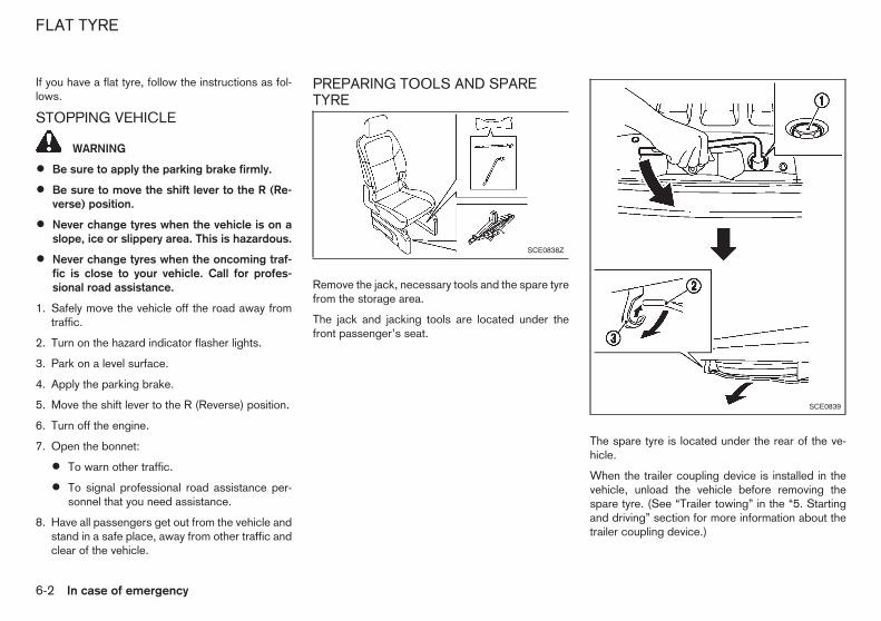
If you have a flat tyre, follow the instructions as fol-lows.
STOPPING VEHICLE
WARNING
• Be sure to apply the parking brake firmly.
• Be sure to move the shift lever to the R (Re-verse) position.
• Never change tyres when the vehicle is on aslope, ice or slippery area. This is hazardous.
• Never change tyres when the oncoming traf-fic is close to your vehicle. Call for profes-sional road assistance.
1. Safely move the vehicle off the road away fromtraffic.
2. Turn on the hazard indicator flasher lights.
3. Park on a level surface.
4. Apply the parking brake.
5. Move the shift lever to the R (Reverse) position.
6. Turn off the engine.
7. Open the bonnet:
• To warn other traffic.
• To signal professional road assistance per-sonnel that you need assistance.
8. Have all passengers get out from the vehicle andstand in a safe place, away from other traffic andclear of the vehicle.
PREPARING TOOLS AND SPARETYRE
Remove the jack, necessary tools and the spare tyrefrom the storage area.
The jack and jacking tools are located under thefront passenger’s seat.
The spare tyre is located under the rear of the ve-hicle.
When the trailer coupling device is installed in thevehicle, unload the vehicle before removing thespare tyre. (See “Trailer towing” in the “5. Startingand driving” section for more information about thetrailer coupling device.)
SCE0838Z
SCE0839
FLAT TYRE
6-2 In case of emergency

To remove the spare tyre, perform the following pro-cedures.
Spare tyre1. Open the back door.
2. Loosen the bolt j1 anticlockwise approximately40 turns using the wheel nut wrench to lower thespare tyre.
3. Stop turning the bolt when the tyre is lowered tothe place where the tyre basket j2 can be re-moved from the hook j3 .
Do not loosen the bolt excessively, otherwisethe basket may fall suddenly.
4. Hold the tyre basket and remove it from the hookby pushing the basket upward.
5. Lower the tyre basket slowly to the ground, andthen take out the spare tyre.
Spare tyre basket bolt tightening torque:
24.5 to 29.4 N•m (2.5 to 2.9 kg-m, 18 to 21 ft-lb)
BLOCKING WHEELS
WARNING
Be sure to block the appropriate wheel to pre-vent the vehicle from moving, which may causepersonal injury.
Place suitable blocks j1 at both the front and backof the wheel diagonally opposite the flat tyre jA toprevent the vehicle from moving when it is jackedup.
REMOVING TYRE
Removing wheel cover (where fitted)
WARNING
Never use your hands to remove the wheel cover.This may cause personal injury.
To remove the wheel cover, use the jack rod j1 asillustrated.
Apply cloth j2 between the wheel and jack rod toprevent damaging the wheel and wheel cover.
MCE0001DZ SCE0630Z
In case of emergency 6-3

Removing wheel centre cap(where fitted)To remove the wheel centre cap, turn it anticlock-wise as illustrated.
Jacking up vehicle
WARNING
• Be sure to read and follow the instructions inthis section.
• Do not get under a vehicle that is supportedonly by a jack: Use vehicle support stands.
• Never use a jack which is not provided withyour vehicle.
• The jack, which is provided with your vehicle,is designed only to lift your vehicle during atyre change. Do not use the jack provided withyour vehicle on other vehicles.
• Never jack up the vehicle at a location otherthan the jack-up point that is specified.
• Never lift the vehicle more than necessary.
• Never use blocks on or under the jack.
• Never start or run the engine while the vehicleis on the jack. The vehicle may move sud-denly, and this may cause an accident.
• Never allow passengers to remain in the ve-hicle while the tyre is off the ground.
• Be sure to read the caution label attached tothe jack body before using.
1. Place the jack directly under the jack-up point asillustrated so that the top of the jack contacts thevehicle at the jack-up point.
The jack should be placed on firm levelground.
2. Align the jack head between the two notcheslocated at the jack-up point of either the front orthe rear section.
3. Fit the groove of the jack head between thenotches as shown.
4. Loosen each wheel nut, anticlockwise, one ortwo turns with the wheel nut wrench.
SCE0637Z
SCE0842Z
Jack-up points
SCE0574Z
6-4 In case of emergency

Do not remove the wheel nuts until the tyre isoff the ground.
5. Carefully raise the vehicle until the clearance be-tween the tyre and ground is achieved.
6. To lift the vehicle, securely hold the jack leverand rod with both hands and turn the jack lever.
Removing tyre1. Remove the wheel nuts.
2. Remove the damaged tyre.
CAUTION
The tyre is heavy. Be sure that your feet are clearfrom the tyre and use gloves as necessary toavoid injury.
INSTALLING SPARE TYRE
WARNING
• Never use wheel nuts which are not providedwith your vehicle. Incorrect wheel nuts or im-
properly tightened wheel nuts may cause thewheel to become loose or come off. Thiscould cause an accident.
• Never use oil or grease on the wheel studs ornuts. This may cause the wheel nuts to be-come loose.
1. Clean any mud or dirt from the surface betweenthe wheel and hub.
2. Carefully put the spare tyre on and tighten thewheel nuts with your fingers. Check that all thewheel nuts contact the wheel surface horizon-tally.
3. Tighten the wheel nuts alternately and evenly inthe sequence illustrated (j1 - j4 ), more than 2times with the wheel nut wrench, until they aretight.
4. Lower the vehicle slowly until the tyre touchesthe ground.
5. Tighten the wheel nuts securely, with the wheelnut wrench, in the sequence illustrated.
6. Lower the vehicle completely.
Tighten the wheel nuts to the specified torquewith a torque wrench as soon as possible.
Wheel nut tightening torque:108 N•m (11 kg-m, 80 ft-lb)
The wheel nuts must be kept tightened to speci-fication at all times. It is recommended that thewheel nuts be tightened to specification at eachlubrication interval.
WARNING
Retighten the wheel nuts when the vehicle hasbeen driven for 1,000 km (600 miles) (also incases of a flat tyre, etc.).
STOWING DAMAGED TYRE ANDTOOLS
WARNING
Be sure that the tyre, jack and tools used areproperly stored after use. Such items can be-come dangerous projectiles in an accident orsudden stop.
1. Securely store the damaged tyre, jack and toolsused in the storage area in the reverse order ofremoval. (See “Preparing tools and spare tyre”earlier in this section.)
2. Close the back door.
SCE0576Z
In case of emergency 6-5

WARNING
• Incorrect jump starting can lead to a batteryexplosion. The battery explosion may result insevere injury or death. It may also result indamage to the vehicle. Be sure to follow theinstructions in this section.
• Explosive hydrogen gas is always present inthe vicinity of the battery. Keep all sparks andflames away from the battery.
• Always wear suitable eye protection and re-move rings, bracelets, and any other jewellerywhenever working on or near a battery.
• Never lean over the battery while jump start-ing.
• Never allow battery fluid to come into contactwith eyes, skin, clothes or the vehicle’spainted surfaces. Battery fluid is a corrosivesulphuric acid which can cause severe burns.If the fluid comes into contact with anything,immediately flush the contacted area withplenty of water.
• Keep the battery out of the reach of children.
• The booster battery must be rated at 12 volts.Use of an incorrectly rated battery will dam-age your vehicle.
• Never attempt to jump start a frozen battery.It could explode and cause serious injury.
1. If the booster battery is in another vehicle jB ,position the two vehicles jA and jB to bring thebatteries into close proximity to each other.
CAUTION
If the battery of vehicle jA equipped with theIntelligent Key system is discharged, the ignitionswitch cannot be moved from the LOCK positionand, if the steering lock is engaged, the steering
wheel cannot be moved. Connect the jumpercables to the booster vehicle jB before turningthe ignition switch and disengaging the steeringlock.
2. Apply the parking brake.
3. Move the shift lever to the N (Neutral) position.
4. Switch off all unnecessary electrical systems(headlights, heater, air conditioner, etc.).
5. Turn the ignition switch to the LOCK position.
6. Remove the vent caps, where fitted, on the bat-tery.
7. Cover the battery with a firmly wrung out moistcloth to reduce the hazard of an explosion.
8. Connect the jumper cables in the sequence asillustrated (j1 , j2 , j3 , j4 ).
CAUTION
• Always connect positive j+ to positive j+ andnegative j- to body ground, NOT to the bat-tery’s negative j- .
• Be sure that the jumper cables do not touchmoving parts in the engine compartment.
• Be sure that the jumper cable’s clamps donot contact any other metal.
9. Start the engine of the booster vehicle jB and letit run for a few minutes.
10. Depress the accelerator pedal of the boostervehicle jB at about 2,000 rpm.
SCE0840Z
HR16DE engine model
SCE0848Z
K9K engine model
JUMP STARTING
6-6 In case of emergency

11. Start the engine of the jumped vehicle jA in thenormal manner.
CAUTION
Never keep the starter motor engaged for morethan 10 seconds. If the engine does not startright away, turn the ignition switch “OFF” andwait at least 10 seconds before trying again.
12. After the engine is started, carefully disconnectthe jumper cables in the opposite sequencefrom that illustrated (j4 , j3 , j2 , j1 ).
13. Remove and dispose of the cloth as it may becontaminated with corrosive acid.
14. Replace the vent caps, if removed.
Do not attempt to start the engine by pushing thevehicle.
CAUTION
• Catalyst equipped model should not bestarted by pushing. Attempting to do so maycause damage to the catalyst.
• Never try to start the engine by towing. Whenthe engine starts, the forward surge couldcause the vehicle to collide with the towingvehicle.
WARNING
• Never continue driving if your vehicle over-heats. Doing so could cause a vehicle fire.
• Never open the bonnet if steam is comingout.
• Never remove the radiator or coolant reser-voir cap while the engine is hot. If the radiatoror coolant reservoir cap is removed when theengine is hot, pressurised hot water will spurtout and possibly cause burning, scalding orserious injury.
• If steam or coolant is coming from the engine,stand clear of the vehicle to prevent gettingburned.
• The engine cooling fan can start at any timewhen the coolant temperature exceeds pre-set degrees.
• Be careful not to allow your hands, hair, jewel-lery or clothing to come into contact with, orto get caught in the cooling fan or drive belts.
If your vehicle is overheating (indicated by the hightemperature indicator), or if you feel a lack of enginepower, detect unusual noise, etc., take the followingsteps:
1. Safely move the vehicle off the road away fromtraffic.
2. Turn on the hazard indicator flasher lights.
3. Apply the parking brake.
PUSH STARTING IF YOUR VEHICLE OVERHEATS
In case of emergency 6-7

4. Move the shift lever to the N (Neutral) position.
DO NOT STOP THE ENGINE.
5. Open all the windows.
6. Turn off the air conditioner (where fitted). Movethe temperature control to maximum hot and thefan control to high speed.
7. Get out from the vehicle.
8. Visually inspect and listen for steam or coolantescaping from the radiator before opening thebonnet. Wait until no steam or coolant can beseen before proceeding.
9. Open the engine bonnet.
10. Visually inspect if the cooling fan is running.
11. Visually inspect the radiator and radiator hosesfor leakage.
If the cooling fan is not running or the coolant isleaking, stop the engine.
12. After the engine cools down, check the coolantlevel in the reservoir with the engine running.Do not open the radiator cap (if equipped).
13. Add coolant to the reservoir if necessary.
WARNING
Before removing the engine coolant reservoir capand to avoid the danger of being scalded, coverthe reservoir cap with a rag and loosen the res-ervoir cap to the first notch to allow the steam toescape.
Have your vehicle inspected/repaired at a NISSANdealer or qualified workshop.
When towing your vehicle, local regulations for tow-ing must be followed. Incorrect towing equipmentcould damage your vehicle. To assure proper tow-ing and to prevent accidental damage to your ve-hicle, NISSAN recommends that you have profes-sional road assistance personnel tow your vehicle. Itis advisable to have the professional road assistantcarefully read the following precautions.
TOWING PRECAUTIONS
• Be sure that the transmission, steering system,and drivetrain are in working condition beforetowing. If any units are damaged, the vehiclemust be towed using a dolly or flatbed tow truck.
• NISSAN recommends that your vehicle be towedwith the driving (front) wheels off the ground.
• Always attach safety chains before towing.
TOWING RECOMMENDED BYNISSAN
SCE0843Z
TOWING YOUR VEHICLE
6-8 In case of emergency

Towing the vehicleFront wheels on the ground:
NISSAN recommends that towing dollies be usedunder the front wheels when towing your vehicle orthe vehicle be placed on a flatbed tow truck as illus-trated.
Manual Transmission (MT) model:
If you have to tow a MT vehicle with front wheel onthe ground, perform the following procedures.
1. Turn the ignition switch to the “OFF” position.
2. Secure the steering wheel in a straight-aheadposition with rope or a similar device.
3. Move the shift lever to the N (Neutral) position.
4. Release the parking brake.
5. Attach the safety chains whenever towing.
Rear wheels on the ground:
1. Turn the ignition switch to the “OFF” position.
2. Move the shift lever to the N (Neutral) position.
3. Release the parking brake.
4. Attach safety chains whenever towing.
All four wheels on the ground:
NISSAN recommends that the vehicle be placed ona flatbed tow truck as illustrated.
Manual Transmission (MT) model:
If you have to tow a MT vehicle with all four wheelson the ground, perform the following procedures.
CAUTION
• Never tow a manual transmission model back-ward with all four wheels on the ground.
1. Turn the ignition switch to the “OFF” position.
2. Move the shift lever to the N (Neutral) position.
3. Release the parking brake.
Freeing trapped vehicle
WARNING
• Never allow anyone to stand near the towingline during the pulling operation.
• Never spin the tyres at high speed. This couldcause them to explode and result in seriousinjury. Parts of the vehicle could also overheatand be damaged.
In the event that your vehicle’s tyres become trappedin sand, snow, or mud, and the vehicle is unable tofree itself without being pulled, use the recoveryhooks.
• Use the recovery hooks only. Do not attach thepulling device to any other part of the vehiclebody. Otherwise, the vehicle body may be dam-aged.
• Use the recovery hooks to free a vehicle only.
• The recovery hooks are under tremendous stresswhen used to free a trapped vehicle. Always pullthe pulling device straight out from the vehicle.Never pull on the recovery hooks at an angle.
j1 : Remove the hook cover from the bumper with asuitable tool.
SCE0841Z
Front
SCE0847Z
Rear
In case of emergency 6-9
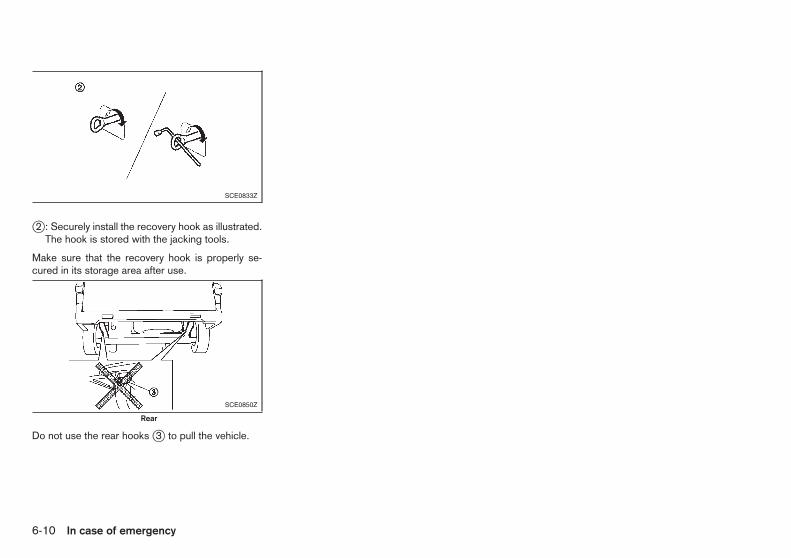
j2 : Securely install the recovery hook as illustrated.The hook is stored with the jacking tools.
Make sure that the recovery hook is properly se-cured in its storage area after use.
Do not use the rear hooks j3 to pull the vehicle.
SCE0833Z
SCE0850Z
Rear
6-10 In case of emergency

7 Appearance and careAppearance and care
Cleaning exterior...................................................... 7-2Washing............................................................. 7-2Removing spots.................................................. 7-2Waxing ............................................................... 7-2Glass ................................................................. 7-3Underbody ......................................................... 7-3Wheels............................................................... 7-3Aluminium alloy wheels ....................................... 7-3Chrome parts ..................................................... 7-3
Cleaning interior ...................................................... 7-3
Floor mats .......................................................... 7-4Glass ................................................................. 7-4Seat belts ........................................................... 7-4
Corrosion protection................................................ 7-4Most common factors contributing to vehiclecorrosion ............................................................ 7-4Environmental factors influence the rate ofcorrosion ............................................................ 7-4To protect your vehicle from corrosion ................ 7-5

In order to maintain the appearance of your vehicle,it is important to take proper care of it.
Whenever possible, park your vehicle inside a ga-rage or in a covered area to minimise the chancesof damaging the paint surface of your vehicle.
When it is necessary to park outside, park in a shadyarea or protect the vehicle with a body cover. Becareful not to scratch the paint surface when put-ting on or removing the body cover.
WASHINGIn the following instances, wash your vehicle as soonas possible to protect the paint surface:
• After a rainfall, which may cause the paint sur-face damage from acid rain.
• After driving on coastal roads, which may causerusting from the sea breeze.
• When contaminants such as soot, bird drop-pings, tree sap, metal particles or bugs get onthe paint surface.
• When dust or mud builds up on the paint sur-face.
1. Wash the vehicle surface with a wet sponge andplenty of water.
2. Clean the vehicle surface gently and thoroughlyusing a mild soap, a special vehicle soap or ageneral purpose dishwashing liquid mixed withclean, lukewarm (never hot) water.
CAUTION
• Do not wash the vehicle with strong house-hold soap, strong chemical detergents, petrolor solvents.
• Do not wash the vehicle in direct sunlight orwhile the vehicle body is hot, as the paint sur-face may become water-spotted.
• Avoid using tight-napped or rough cloths,such as washing mitts. Care must be takenwhen removing caked-on dirt or other foreignsubstances so the paint surface is notscratched or damaged.
3. Rinse the vehicle thoroughly with plenty of cleanwater.
4. Use a dampened chamois to dry the paint sur-face and avoid leaving water spots.
When washing the vehicle, take care of the follow-ing:
• Inside flanges, joints and folds on the doors,hatches and bonnet are particularly vulnerable tothe effects of road salt. Therefore, these areasmust be cleaned regularly.
• Be sure that the drain holes in the lower edge ofthe doors are not clogged.
• Spray water to the underbody and in the wheelwells to loosen the dirt and/or wash away roadsalt.
REMOVING SPOTSRemove tar and oil spots, industrial dust, insects,and tree sap as quickly as possible from the paintsurface to avoid lasting damage or staining. Specialcleaning products are available at a NISSAN dealeror qualified workshop or any automotive accessorystore.
WAXINGRegular waxing protects the paint surface and helpsmaintain a new vehicle appearance.
After waxing, polishing is recommended to removebuilt-up residue and to avoid a weathered appear-ance.
A NISSAN dealer or qualified workshop can assistyou in choosing the appropriate waxing products.
CAUTION
• Wash your vehicle thoroughly and completelybefore applying wax to the paint surface.
• Always follow the manufacturer’s instructionssupplied with the wax.
• Do not use a wax containing any abrasives,cutting compounds or cleaners that may dam-age the vehicle finish.
Machine compounding or aggressive polishing on abase coat/clear coat paint finish may dull the finishor leave swirl marks.
CLEANING EXTERIOR
7-2 Appearance and care

GLASSUse glass cleaner to remove smoke and dust filmfrom the glass surfaces. It is normal for glass tobecome coated with a film after the vehicle is parkedin the hot sun. Glass cleaner and a soft cloth willeasily remove this film.
UNDERBODYIn areas where road salt is used in the winter, it isnecessary to clean the vehicle’s underbody regu-larly in order to prevent dirt and salt from building upand causing the acceleration of corrosion on theunderbody and suspension.
Before the winter and again in the spring, the under-seal must be checked and, if necessary, re-treated.
WHEELS
• Wash the wheels when washing the vehicle tomaintain their appearance.
• Clean the inner side of the wheels when thewheel is changed or the underside of the vehicleis washed.
• Do not use abrasive cleaners when washing thewheels.
• Inspect wheel rims regularly for dents or corro-sion. This may cause loss of pressure or damagethe tyre bead.
• NISSAN recommends that the road wheels bewaxed to protect against road salt in areas whereit is used during winter.
ALUMINIUM ALLOY WHEELSWash the wheels regularly with a sponge damp-ened in a mild soap solution, especially during win-ter in areas where road salt is used. The salt residuefrom road salt could discolour the wheels if it is notwashed off regularly.
CAUTION
Follow the directions below to avoid staining ordiscolouring the wheels:
• Do not use a cleaner that uses strong acid oralkali contents to clean the wheels.
• Do not apply wheel cleaners to the wheelswhen they are hot. The wheel temperatureshould be the same as ambient temperature.
• Rinse the wheel to completely remove thecleaner within 15 minutes after the cleaner isapplied.
CHROME PARTSClean all chrome parts regularly with a nonabrasivechrome polish to maintain the finish.
Occasionally remove loose dust from the interiortrim, plastic parts and seats using a vacuum cleaneror soft bristled brush. Wipe the vinyl and leather sur-faces with a clean, soft cloth dampened in mild soapsolution, then wipe clean with a dry, soft cloth.
Regular care and cleaning is required in order tomaintain the appearance of the leather.
Before using any fabric protector, read the manu-facturer’s recommendations. Some fabric protec-tors contain chemicals that may stain or bleach theseat material.
Use a soft cloth dampened only with water to cleanthe meter and gauge lens covers.
CAUTION
• Never use benzine, thinner or any similar ma-terial.
• Small dirt particles can be abrasive and dam-aging to leather surfaces and should be re-moved promptly. Do not use saddle soap, carwaxes, polishes, oils, cleaning fluids,solvents, detergents or ammonia-basedcleaners as they damage the natural leatherfinish.
• Never use fabric protectors unless recom-mended by the manufacturer.
• Do not use glass or plastic cleaner on meteror gauge lens covers. It may damage the lenscovers.
CLEANING INTERIOR
Appearance and care 7-3

FLOOR MATSThe use of Genuine NISSAN floor mats (where fit-ted) can extend the life of your vehicle carpet andmake it easier to clean the interior. Regardless ofwhat mats are used, be sure they are fitted for yourvehicle and are properly positioned in the foot wellto prevent interference with pedal operation. Matsshould be maintained with regular cleaning and re-placed if they become excessively worn.
Floor mat positioning aidThis vehicle includes front floor mat brackets jA toact as a floor mat positioning aid. NISSAN floormats have been specially designed for your vehiclemodel.
Position the mat by placing the floor mat brackethook through the floor mat grommet hole while cen-tering the mat in the foot area.
Periodically check that the mats are properly posi-tioned.
GLASSUse glass cleaner to remove smoke and dust filmfrom the glass surfaces. It is normal for glass tobecome coated with a film after the vehicle is parkedin the hot sun. Glass cleaner and a soft cloth willeasily remove this film.
CAUTION
When cleaning the inside of the windows, do notuse sharp-edged tools, abrasive cleaners or chlo-rine-based disinfectant cleaners. They coulddamage the electrical conductors, such as rearwindow defogger elements.
SEAT BELTS
WARNING
• Do not allow wet seat belts to roll up in theretractor.
• Never use bleach, dye or chemical solvents toclean the seat belts, since these materialsmay severely weaken the seat belt webbing.
The seat belts can be cleaned by wiping them witha sponge dampened in a mild soap solution.
Allow the belts to dry completely in the shade beforeusing them. (See “Seat belts” in the “1. Safety —seats, seat belts and supplemental restraint system”section.)
MOST COMMON FACTORSCONTRIBUTING TO VEHICLECORROSION
• The accumulation of moisture-retaining dirt anddebris in body panel sections, cavities, and otherareas.
• Damage to the paint surface and other protec-tive coatings caused by gravel and stone chipsor minor traffic accidents.
ENVIRONMENTAL FACTORSINFLUENCE THE RATE OFCORROSION
MoistureThe accumulation of sand, dirt and water on theinside floor of the vehicle can accelerate corrosion.Wet floor carpet/floor mats will not dry completelyinside the vehicle. They should be removed andcompletely dried to avoid floor panel corrosion.
Relative humidityCorrosion will be accelerated in areas of high rela-tive humidity.
TemperatureHigh temperatures accelerate the rate of corrosionto those parts which are not well ventilated.
Corrosion will also be accelerated in areas wherethe temperatures stay above freezing.
SAI0034Z
Example
CORROSION PROTECTION
7-4 Appearance and care
Air pollutionIndustrial pollution, the presence of salt in the air incoastal areas, or heavy road salt use acceleratesthe corrosion process. Road salt also acceleratesthe disintegration of paint surfaces.
TO PROTECT YOUR VEHICLE FROMCORROSION
• Wash and wax your vehicle often to keep thevehicle clean.
• Always check for minor damage to the paint sur-face and if any exists, repair it as soon as pos-sible.
• Keep the drain holes in the lower edge of thedoors open to avoid water accumulation.
• Check the vehicle underbody for accumulationof sand, dirt or salt. If present, wash with wateras soon as possible.
CAUTION
• Never remove dirt, sand or other debris fromthe passenger compartment by washing it outwith a hose. Remove dirt with a vacuumcleaner.
• Never allow water or other liquids to come incontact with electronic components inside thevehicle as this may damage them.
Chemicals used for road surface deicing are ex-tremely corrosive. They accelerate corrosion and
deterioration of underbody components such as theexhaust system, fuel and brake lines, brake cables,floor pan and fenders.
In the winter, the underbody must be cleanedperiodically.
For additional protection against rust and corrosion,which may be required in some areas, consult aNISSAN dealer or qualified workshop.
Appearance and care 7-5

NOTE
7-6 Appearance and care

8 Maintenance and do-it-yourselfMaintenance and do-it-yourself
Maintenance requirements ....................................... 8-2Scheduled maintenance...................................... 8-2General maintenance.......................................... 8-2Where to go for service ...................................... 8-2
General maintenance............................................... 8-2Explanation of general maintenance items ........... 8-2Maintenance precautions .................................... 8-4
Engine compartment check locations ....................... 8-5Engine cooling system ............................................. 8-5
Checking engine coolant level............................. 8-5Changing engine coolant .................................... 8-6
Engine oil................................................................. 8-6Checking engine oil level .................................... 8-6Changing engine oil and oil filter ......................... 8-7Protect environment............................................ 8-9
Fuel filter (diesel engine model)................................ 8-9Draining water .................................................... 8-9Bleeding fuel system........................................... 8-10
Drive belt ................................................................. 8-11Spark plugs (petrol engine model)............................ 8-11
Platinum-tipped spark plugs................................ 8-11Brakes..................................................................... 8-12
Checking parking brake...................................... 8-12Checking footbrake pedal................................... 8-12Brake booster..................................................... 8-13
Brake fluid ............................................................... 8-13Clutch fluid .............................................................. 8-14
Air cleaner filter........................................................ 8-14Wiper blades ........................................................... 8-15
Windscreen wiper blades ................................... 8-15Rear window wiper blade ................................... 8-16
Window washer fluid ............................................... 8-16Battery..................................................................... 8-17
Vehicle battery.................................................... 8-17Integrated keyfob battery .................................... 8-18Intelligent key battery .......................................... 8-19
Fuses ...................................................................... 8-20Engine compartment........................................... 8-20Passenger compartment ..................................... 8-21
Lights ...................................................................... 8-21Headlights .......................................................... 8-21Exterior lights...................................................... 8-22Interior lights....................................................... 8-22Light locations .................................................... 8-23
Tyres and wheels..................................................... 8-26Tyre inflation pressure......................................... 8-26Types of tyres..................................................... 8-26Tyre chains......................................................... 8-27Tyre rotation ....................................................... 8-27Tyre wear and damage ....................................... 8-27Tyre age ............................................................. 8-27Changing tyres and wheels................................. 8-28Wheel balance.................................................... 8-28Spare tyre .......................................................... 8-28
Your new vehicle has been designed to have mini-mum maintenance requirements with long serviceintervals to save you both time and money. How-ever, some day-to-day and regular maintenance isessential to maintain your vehicle’s fine mechanicalcondition, as well as its emission and engine perfor-mance.
It is the owner’s responsibility to make sure that thespecified maintenance, as well as general mainte-nance, is performed.
As the vehicle owner, you are the only one who canensure that your vehicle receives the proper mainte-nance care. You are a vital link in the maintenancechain.
SCHEDULED MAINTENANCEFor your convenience, the required scheduled main-tenance items are described and listed in a separatemaintenance booklet. You must refer to that bookletto ensure that necessary maintenance is performedon your vehicle at regular intervals.
GENERAL MAINTENANCEGeneral maintenance includes those items whichshould be checked during normal day-to-day opera-tion of the vehicle. They are essential if your vehicleis to continue to operate properly. It is your respon-sibility to perform these procedures regularly as pre-scribed.
Performing general maintenance checks requiresminimal mechanical skill and only a few general au-tomotive tools.
These checks and inspections can be done by your-self, a qualified technician, or if you prefer, aNISSAN dealer or qualified workshop.
WHERE TO GO FOR SERVICEIf maintenance service is required or your vehicleappears to malfunction, have the systems checkedand tuned by a NISSAN dealer or qualified work-shop.
NISSAN technicians are well-trained specialists andare kept up-to-date with the latest service informa-tion through technical bulletins, service tips, and in-ternal dealership training programs. They are com-pletely qualified to work on NISSAN’s vehicles be-fore they work on your vehicle, rather than after theyhave worked on it.
You can be confident that a NISSAN dealer or quali-fied workshop’s service department performs thebest job to meet the maintenance requirements onyour vehicle — in a reliable and economic way.
During normal day-to-day operation of the vehicle,general maintenance should be performed regularlyas prescribed in this section. If you detect any un-usual sounds, vibrations or smells, be sure to checkfor the cause or have a NISSAN dealer or qualifiedworkshop do it promptly. In addition, you shouldnotify a NISSAN dealer if you think that repairs arerequired.
When performing any checks or maintenance work,closely observe “Maintenance precautions” later inthis section.
EXPLANATION OF GENERALMAINTENANCE ITEMSAdditional information on the following items with“*” is found later in this section.
Outside vehicleThe maintenance items listed here should be per-formed from time to time, unless otherwise speci-fied.
Doors and engine bonnet:
Check that all doors and the engine bonnet operateproperly. Also make sure that all latches lock se-curely. Lubricate hinges and latches if necessary.Make sure that the secondary latch of the enginebonnet keeps the bonnet from opening when theprimary latch is released.
When driving in areas using road salt or other cor-rosive materials, check lubrication frequently.
MAINTENANCE REQUIREMENTS GENERAL MAINTENANCE
8-2 Maintenance and do-it-yourself
Lights*:
Clean the headlights on a regular basis. Make surethat the headlights, stop lights, tail lights, turn signallights, and other lights are all operating properly andinstalled securely. Also check the aim of the head-lights.
Tyres*:
Check the pressure with a gauge often and alwaysprior to long distance trips. If necessary, adjust thepressure in all tyres, including the spare, to the pres-sure specified. Check carefully for damage, cuts orexcessive wear.
Tyre rotation*:
Tyres should be rotated every 10,000 km (6,000miles).
However, the timing for tyre rotation may vary ac-cording to your driving habits and the road surfaceconditions.
Wheel alignment and balance:
If the vehicle should pull to either side while drivingon a straight and level road, or if you detect unevenor abnormal tyre wear, there may be a need forwheel alignment.
If the steering wheel or seat vibrates at normal high-way speeds, wheel balancing may be needed.
Windscreen:
Clean the windscreen on a regular basis. Check thewindscreen at least every six months for cracks orother damage. Have a damaged windscreen re-paired by a qualified repair facility.
Wiper blades*:
Check for cracks or wear if they do not wipe prop-erly.
Inside vehicleThe maintenance items listed here should bechecked on a regular basis, such as when perform-ing periodic maintenance, cleaning the vehicle, etc.
Accelerator pedal:
Check the pedal for smooth operation and makesure that the pedal does not catch or require uneveneffort. Keep the floor mats away from the pedal.
Brake pedal*:
Check the pedal for smooth operation and makesure that it has the proper distance under it whendepressed fully. Check the brake booster function.Keep the floor mats away from the pedal.
Parking brake*:
Check that the lever has the proper distance oftravel.
Seat belts:
Check that all parts of the seat belt system (forexample, buckles, anchors, adjusters and retrac-tors) operate properly and smoothly, and that theyare installed securely. Check the belt webbing forcuts, fraying, wear or damage.
Steering wheel:
Check for changes in the steering conditions, suchas excessive free play, hard steering or strangenoises.
Warning lights and chimes:
Make sure that all warning lights and chimes areoperating properly.
Windscreen defogger:
Check that the air comes out of the defogger outletsproperly and in good quantity when operating theheater or air conditioner.
Windscreen wiper and washer*:
Check that the wipers and washer operate properlyand that the wipers do not streak.
Under bonnet and vehicleThe maintenance items listed here should bechecked periodically (for example, each time youcheck the engine oil or refuel).
Battery*:
Check the fluid level in each cell. It should be be-tween the UPPER and LOWER levels. Vehicles op-erated in high temperatures or under severe condi-tions require frequent checks of the battery fluidlevel.
Brake fluid level*:
Make sure that the brake fluid level is between theMAX and MIN lines on the reservoir.
Clutch fluid level*:
Make sure that the clutch fluid level is between theMAX and MIN lines on the reservoir.
Engine coolant level*:
Check the coolant level when the engine is cold.
Maintenance and do-it-yourself 8-3

Engine drive belts*:
Make sure that the drive belts are not frayed, worn,cracked or oily.
Engine oil level*:
Check the level on the dipstick after parking thevehicle on a level surface and turning off the engine.
Fluid leaks:
Check under the vehicle for fuel, oil, water or otherfluid leaks after the vehicle has been parked for awhile. Water dripping from the air conditioner afteruse is normal. If you should notice any leaks or if fuelfumes are evident, check for the cause and have itcorrected immediately.
Window washer fluid*:
Check that there is adequate fluid in the reservoir.
MAINTENANCE PRECAUTIONSWhen performing any inspection or maintenancework on your vehicle, always take care to preventserious accidental injury to yourself or damage tothe vehicle. The following are general precautionswhich should be closely observed.
WARNING
• Park the vehicle on a level surface, apply theparking brake securely and block the wheelsto prevent the vehicle from moving. Move theshift lever to the N (Neutral) position.
• Be sure the ignition switch is in the “OFF” orLOCK position when performing any parts re-placement or repairs.
• Do not work under the bonnet while the en-gine is hot. Always turn off the engine andwait until it cools down.
• If you must work with the engine running,keep your hands, clothing, hair and tools awayfrom moving fans, belts and any other movingparts.
• It is advisable to secure or remove any looseclothing and any jewellery, such as rings,watches, etc. before working on your vehicle.
• If you must run the engine in an enclosedspace such as a garage, be sure there isproper ventilation for exhaust gases to es-cape.
• Never get under the vehicle while it is sup-ported only by a jack. If it is necessary to workunder the vehicle, support it with safetystands.
• Keep smoking materials, flame and sparksaway from fuel and the battery.
• Never connect or disconnect either the bat-tery or any transistorised component connec-tor while the ignition switch is in the ON posi-tion.
• On petrol engine models with the MultiportFuel Injection (MFI) system, the fuel filter andfuel lines should be serviced by a NISSAN
dealer or qualified workshop because the fuellines are under high pressure even when theengine is turned off.
• Your vehicle is equipped with an automaticengine cooling fan. It may come on at anytime without warning, even if the ignitionswitch is in the “OFF” position and the engineis not running. To avoid injury, always discon-nect the negative battery cable before work-ing near the fan.
• Always wear eye protection whenever youwork on your vehicle.
• Never leave the engine or transmission re-lated component harness connector discon-nected while the ignition switch is in the ONposition.
NISSAN GREEN PROGRAM
Avoid direct contact with used engine oil andcoolant. Improperly disposed engine oil, en-gine coolant, and/or other vehicle fluids canhurt the environment. Always conform to lo-cal regulations for disposal of vehicle fluids.
This “8. Maintenance and do-it-yourself” sectionprovides instructions regarding only those itemswhich are relatively easy for an owner to perform.
You should be aware that incomplete or improperservicing may result in operating difficulties or ex-cessive emissions, and could affect your warrantycoverage. If in doubt about any servicing, have itdone by a NISSAN dealer or qualified workshop.
8-4 Maintenance and do-it-yourself

For an overview of the engine compartment, see“Engine compartment” in the “0. Illustrated tableof contents” section.
WARNING
• Never remove the radiator or coolant reser-voir cap when the engine is hot. Serious burnscould be caused by high-pressure fluid es-caping from the radiator. Wait until the engineand radiator cool down.
• Engine coolant is poisonous and should bestored carefully in marked containers out ofthe reach of children.
The engine cooling system is filled at the factorywith a high-quality, year-round, anti-freeze coolantsolution. The anti-freeze solution contains rust andcorrosion inhibitors, therefore additional cooling sys-tem additives are not necessary.
CAUTION
When adding or replacing coolant, be sure to useonly Genuine NISSAN Engine Coolant or equiva-lent in its quality with the proper mixture ratio.
Use Genuine NISSAN Engine Coolant or equivalentin its quality. Genuine NISSAN Engine Coolant is apre-mixed (mixture ratio 50%) type coolant.
The use of other types of coolant solutions maydamage the engine cooling system.
For HR16DE engine model: The radiator is equippedwith a pressure cap. To prevent engine damage,use only a Genuine NISSAN radiator cap or itsequivalent when replacement is required.
CHECKING ENGINE COOLANTLEVEL
HR16DE engine modelCheck the coolant level in the reservoir tank whenthe engine is cold. If the coolant level is below theMIN level j2 , add coolant up to the MAX level j1 .If the reservoir tank is empty, check the coolant levelin the radiator when the engine is cold. If there isinsufficient coolant in the radiator, fill the radiator
SDI2456Z
HR16DE engine
SDI2463Z
K9K engine
ENGINE COMPARTMENT CHECKLOCATIONS
ENGINE COOLING SYSTEM
Maintenance and do-it-yourself 8-5
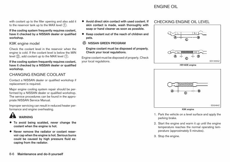
with coolant up to the filler opening and also add itto the reservoir tank up to the MAX level j1 .
If the cooling system frequently requires coolant,have it checked by a NISSAN dealer or qualifiedworkshop.
K9K engine modelCheck the coolant level in the reservoir when theengine is cold. If the coolant level is below the MINlevel j2 , add coolant up to the MAX level j1 .
If the cooling system frequently requires coolant,have it checked by a NISSAN dealer or qualifiedworkshop.
CHANGING ENGINE COOLANTContact a NISSAN dealer or qualified workshop ifreplacement is required.
Major engine cooling system repair should be per-formed by a NISSAN dealer or qualified workshop.The service procedures can be found in the appro-priate NISSAN Service Manual.
Improper servicing can result in reduced heater per-formance and engine overheating.
WARNING
• To avoid being scalded, never change thecoolant when the engine is hot.
• Never remove the radiator or coolant reser-voir cap when the engine is hot. Serious burnscould be caused by high pressure fluid es-caping from the radiator.
• Avoid direct skin contact with used coolant. Ifskin contact is made, wash thoroughly withsoap or hand cleaner as soon as possible.
• Keep coolant out of the reach of children andpets.
NISSAN GREEN PROGRAM
Engine coolant must be disposed of properly.Check your local regulations.
Engine coolant must be disposed of properly. Checkyour local regulations.
CHECKING ENGINE OIL LEVEL
1. Park the vehicle on a level surface and apply theparking brake.
2. Start the engine and warm it up until the enginetemperature reaches the normal operating tem-perature (approximately 5 minutes).
3. Stop the engine.
SDI1305AZ
HR16DE engine
SDI2464Z
K9K engine
ENGINE OIL
8-6 Maintenance and do-it-yourself

4. Wait at least 10 minutes for the engine oil todrain back to the oil pan.
5. Remove the dipstick and wipe it clean.
6. Reinsert the dipstick all the way.
7. Remove the dipstick and check the oil level. Itshould be within the range jC .
8. If the oil level is below jA , remove the oil fillercap and pour the recommended oil into the open-ing. Do not overfill jB .
When filling the engine oil, do not remove thedipstick.
9. Recheck the oil level with the dipstick.
It is normal to add some oil between oil main-tenance intervals or during the running-in pe-riod, depending on the severity of operatingconditions.
CAUTION
The oil level should be checked regularly. Oper-ating your vehicle with an insufficient amount ofoil can damage the engine, and such damage isnot covered by the warranty.
CHANGING ENGINE OIL AND OILFILTER
WARNING
NISSAN GREEN PROGRAM
Used oil must be disposed of properly. Neverpour or dump oil into the ground, canals, riv-
ers, etc. It should be disposed of at properwaste facilities. We recommend having youroil changed by a NISSAN dealer or qualifiedworkshop.
• Be careful not to burn yourself, as the engineoil may be hot.
• Prolonged and repeated contact with usedengine oil may cause skin cancer.
• Avoid direct skin contact with used oil. If con-tacted, wash thoroughly with soap or handcleaner and plenty of water as soon as pos-sible.
• Store used engine oil in marked containersout of the reach of children.
1. Park the vehicle on a level surface and apply theparking brake.
2. Start the engine and warm it up until the enginetemperature reaches the normal operating tem-perature (approximately 5 minutes).
3. Stop the engine.
4. Wait at least 10 minutes for the engine oil todrain back to the oil pan.
5. Raise and support the vehicle using a suitablefloor jack and safety jack stands.
• Place the safety jack stands under the vehiclejack-up points.
• A suitable adapter should be attached to the jackstand saddle.
6. Remove the plastic engine undercover, if neces-sary, by removing the bolts and plastic clips.
j1 Oil drain plug
j2 Oil filter
Engine oil and filterHR16DE engine:
1. Place a large drain pan under the drain plug.
2. Remove the drain plug with a wrench.
3. Remove the oil filler cap and completely drain theoil.
If the oil filter is to be changed, remove and re-place it at this time.
CAUTION
Waste oil must be disposed of properly. Checkyour local regulations.
4. Loosen the oil filter with an oil filter wrench.
5. Remove the oil filter by turning it by hand.
SDI2458Z
HR16DE engine
Maintenance and do-it-yourself 8-7

6. Wipe the oil filter mounting surface with a cleancloth.
Be sure to remove any old gasket remaining onthe mounting surface.
7. Apply new engine oil to the gasket of the new oilfilter.
8. Screw in the oil filter until a slight resistance isfelt and then tighten an additional 2/3 of a turn tosecure the filter.Oil filter tightening torque:HR16DE engine
15 to 20 N•m(1.5 to 2.0 kg-m, 11 to 15 ft-lb)
9. Clean and reinstall the drain plug and newwasher. Securely tighten the drain plug with awrench. Do not use excessive force.Drain plug tightening torque:HR16DE engine
29 to 39 N•m(3.0 to 4.0 kg-m, 22 to 29 ft-lb)
10. Refill the recommended engine oil and quantity.(See “Recommended fuel/lubricants andcapacities” in the “9. Technical information”section.)
When filling the engine oil, do not removethe dipstick.
11. Securely install the oil filler cap.
12. Start the engine.
13. Check the drain plug and the oil filter for anysign of leakage.
14. Dispose of the used oil in the proper manner.Check your local regulations.
15. Check the engine oil level according to theproper procedure. (See “Checking engine oillevel” earlier in this section.)
j1 Oil drain plug
j2 Oil filter
K9K engine:
1. Place a large drain pan under the drain plug.
2. Remove the drain plug with a wrench.
3. Remove the oil filler cap and completely drain theoil.
If the oil filter is to be changed, remove and re-place it at this time.
CAUTION
Waste oil must be disposed of properly. Checkyour local regulations.
4. Loosen the oil filter with an oil filter wrench.
5. Remove the oil filter by turning it by hand.
6. Wipe the entire oil filter mounting surface with aclean cloth.
Be sure to remove any old gasket remaining onthe mounting surface.
7. Apply new engine oil to the gasket on the new oilfilter.Drain plug tightening torque:K9K engine
44 N•m(4.5 kg-m, 32 ft-lb)
8. Screw in the oil filter until a slight resistance isfelt, and then tighten an additional 3/4 of a turn tosecure the filter.Oil filter tightening torque:K9K engine
25 N•m(2.6 kg-m, 18 ft-lb)
9. Clean and reinstall the drain plug and newwasher. Securely tighten the drain plug with awrench. Do not use excessive force.
10. Refill the recommended engine oil and quantity.(See “Recommended fuel/lubricants andcapacities” in the “9. Technical information”section.)
11. Securely install the oil filler cap.
12. Start the engine.
SDI2465Z
K9K engine
8-8 Maintenance and do-it-yourself
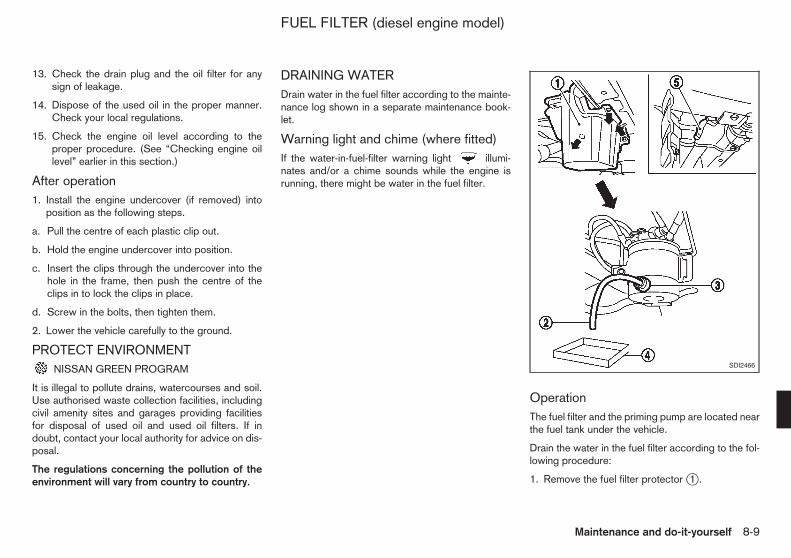
13. Check the drain plug and the oil filter for anysign of leakage.
14. Dispose of the used oil in the proper manner.Check your local regulations.
15. Check the engine oil level according to theproper procedure. (See “Checking engine oillevel” earlier in this section.)
After operation1. Install the engine undercover (if removed) into
position as the following steps.
a. Pull the centre of each plastic clip out.
b. Hold the engine undercover into position.
c. Insert the clips through the undercover into thehole in the frame, then push the centre of theclips in to lock the clips in place.
d. Screw in the bolts, then tighten them.
2. Lower the vehicle carefully to the ground.
PROTECT ENVIRONMENTNISSAN GREEN PROGRAM
It is illegal to pollute drains, watercourses and soil.Use authorised waste collection facilities, includingcivil amenity sites and garages providing facilitiesfor disposal of used oil and used oil filters. If indoubt, contact your local authority for advice on dis-posal.
The regulations concerning the pollution of theenvironment will vary from country to country.
DRAINING WATERDrain water in the fuel filter according to the mainte-nance log shown in a separate maintenance book-let.
Warning light and chime (where fitted)If the water-in-fuel-filter warning light illumi-nates and/or a chime sounds while the engine isrunning, there might be water in the fuel filter.
OperationThe fuel filter and the priming pump are located nearthe fuel tank under the vehicle.
Drain the water in the fuel filter according to the fol-lowing procedure:
1. Remove the fuel filter protector j1 .
SDI2466
FUEL FILTER (diesel engine model)
Maintenance and do-it-yourself 8-9

2. Connect a suitable drain hose j2 to the drainvalve j3 .
3. Place a container j4 under the fuel filter.
4. Loosen the drain valve j3 4 to 5 turns to drainthe water. To avoid dropping it, do not loosen thedrain valve too much. If water does not drainproperly, operate the priming pump j5 . (Thepriming pump can also be accessed from theinside of the vehicle. See “Bleeding fuel system”later in this section.)
5. After the water has been completely drained,close the drain valve j3 .
6. Bleed any air from the fuel system. (See “Bleed-ing fuel system” later in this section.)
BLEEDING FUEL SYSTEM
Bleed air out of the fuel system after refilling anempty fuel tank by the following procedure:
1. Slide the front right-side seat forward.
2. Turn the clips clockwise to remove the cover andaccess the priming pump j1 .
3. Squeeze the priming pump j1 several times untilthere is a sudden resistance felt in the pressure,then stop.
4. Crank the engine until it starts. Do not crank theengine for more than 30 seconds.
5. If the engine does not start, stop cranking andrepeat step 3 above.
6. If the engine does not operate smoothly after ithas started, race it two or three times.
If the engine does not start after performing theabove procedures, see a NISSAN dealer or quali-fied workshop.
SDI2467
8-10 Maintenance and do-it-yourself

1. Water pump
2. Alternator
3. Crankshaft pulley
4. Air conditioner compressor (where fitted)
▼: Tension checking point
1. Crankshaft pulley
2. Drive belt auto-tensioner (where fitted)
3. Alternator
4. Air conditioner compressor (where fitted)
▼: Tension checking point (model without airconditioner)
Be sure the ignition switch is in the “OFF” position.
Visually inspect the belt for signs of unusual wear,cuts, fraying or looseness. Check regularly for con-dition and tension. If the belt is in poor condition orloose, have it replaced or adjusted by a NISSANdealer or qualified workshop.
WARNING
Be sure the engine and ignition switch are offand that the parking brake is applied.
Replace the spark plugs according to the mainte-nance log shown in a separate maintenance book-let.
If replacement is required, contact a NISSAN dealeror qualified workshop.
PLATINUM-TIPPED SPARK PLUGS
It is not necessary to replace the platinum-tippedspark plugs as frequently as the conventional typeof spark plugs. These spark plugs are designed tolast much longer than the conventional type of sparkplugs.
CAUTION
• Do not reuse the platinum-tipped spark plugsby cleaning or re-gapping.
SDI1862Z
HR16DE engine model
SDI2468Z
K9K engine
SDI2020Z
DRIVE BELT SPARK PLUGS (petrol enginemodel)
Maintenance and do-it-yourself 8-11

• Always replace with the recommended plati-num-tipped spark plugs.
CHECKING PARKING BRAKE
Lever typeFrom the released position, pull the parking brakelever up slowly and firmly. If the number of clicks isout of the range listed, see a NISSAN dealer orqualified workshop.
6 to 7 clicksPulling force 196 N (20 kg, 44 lb)
CHECKING FOOTBRAKE PEDAL
WARNING
See a NISSAN dealer or qualified workshop for abrake system check if the footbrake pedal heightdoes not return to normal.
With the engine running, check the distance jAbetween the upper surface of the pedal and theupper surface of the steering hole cover. If it is outthe range listed, see a NISSAN dealer or qualifiedworkshop.
jA : 80 mm (3.15 in) or more under a depress-ing force of 490 N (50 kg, 110 lb)
Self-adjusting brakesYour vehicle is equipped with self-adjusting brakes.The disc-type brakes self-adjust every time the foot-brake pedal is applied.
Brake pad wear warningThe disc brake pads have audible wear warnings.When a brake pad requires replacement, it will makea high pitched scraping sound when the vehicle is inmotion. This scraping sound will first occur onlywhen the brake pedal is depressed. After more wearof the brake pad, the sound will always be heardeven if the brake pedal is not depressed. Have thebrakes checked as soon as possible if the wearwarning sound is heard.
Under some driving or climate conditions, occa-sional brake squeaks, squeals or other noises maybe heard. Occasional brake noise during light tomoderate stops is normal and does not affect thefunction or performance of the brake system.
SDI1447AZ
SDI2453Z
BRAKES
8-12 Maintenance and do-it-yourself

Proper brake inspection intervals should befollowed. For additional information, see a separatemaintenance booklet.
BRAKE BOOSTERCheck the brake booster function as follows:
1. With the engine off, depress and release thefootbrake pedal several times. When the brakepedal movement (distance of travel) remains thesame from one pedal application to the next, con-tinue on to the next step.
2. While depressing the footbrake pedal, start theengine. The pedal height should drop a little.
3. With the footbrake pedal depressed, stop theengine. Keep the pedal depressed for about 30seconds. The pedal height should not change.
4. Run the engine for 1 minute without depressingthe footbrake pedal, then turn it off. Depress thefootbrake pedal several times. The pedal traveldistance will decrease gradually with each de-pression as the vacuum is released from thebooster.
If the brakes do not operate properly, have thebrakes checked by a NISSAN dealer or qualifiedworkshop.
WARNING
• Use only new fluid from a sealed container.Old, inferior, or contaminated fluid may dam-age the brake system. The use of improperfluids can damage the brake system and af-fect the vehicle’s stopping ability.
• Clean the filler cap before removing.
• Brake fluid is poisonous and should be storedcarefully in marked containers out of the reachof children.
CAUTION
Do not spill the fluid on painted surfaces. Thiswill damage the paint. If fluid is spilled, wash itoff with plenty of water immediately.
Check the fluid level in the reservoir. If the fluid isbelow the MIN line j2 , the brake warning light willilluminate. Add fluid up to the MAX line j1 . (See
“Recommended fuel/lubricants and capacities” inthe “9. Technical information” section for recom-mended types of fluid.)
If the fluid must be added frequently, the systemshould be thoroughly checked by a NISSAN dealeror qualified workshop.
SDI2459Z
BRAKE FLUID
Maintenance and do-it-yourself 8-13

WARNING
• Use only new fluid from a sealed container.Old, inferior, or contaminated fluid may dam-age the clutch system.
• Clean the filler cap before removing.
• Clutch fluid is poisonous and should be storedcarefully in marked containers out of the reachof children.
CAUTION
Do not spill the clutch fluid on painted surfaces.This will damage the paint. If clutch fluid is spilled,wash it off with plenty of water immediately.
Check the fluid level in the reservoir. If the fluid isbelow the MIN line j2 , add fluid up to the MAX linej1 . (See “Recommended fuel/lubricants andcapacities” in the “9. Technical information” sectionfor the recommended types of fluid.)
If the fluid must be added frequently, the clutch sys-tem should be thoroughly checked by a NISSANdealer or qualified workshop.
WARNING
Operating the engine with the air cleaner filter offcan cause you or others to be burned. The aircleaner filter not only cleans the intake air, it alsostops flame if the engine backfires. If the aircleaner filter is not installed and the engine back-fires, you could be burned. Never drive with theair cleaner filter off. Be cautious working on theengine when the air cleaner filter is off.
To remove the filter, push the tabs, and pull the unitupward.
The viscous paper type filter element should not becleaned and reused. The dry paper type filter ele-ment may be cleaned and reused. Replace the airfilter according to the maintenance log shown in aseparate maintenance booklet.
When replacing the air filter, wipe the inside of theair cleaner housing and the cover with a damp cloth.
SDI2459Z
SDI2106Z
CLUTCH FLUID AIR CLEANER FILTER
8-14 Maintenance and do-it-yourself

WINDSCREEN WIPER BLADES
CleaningIf the windscreen does not become clear after usingthe windscreen washer or if the wiper blades chat-ter when operating the windscreen wipers, wax orother materials may be on the windscreen and/orwiper blades.
Clean the outside of the windscreen surface with awasher solution or mild detergent. Your windscreenis clean if beads do not form when rinsing with wa-ter.
Clean the blade by wiping it with a cloth soaked in awasher solution or a mild detergent. Rinse the bladewith water. If your windscreen is still not clear aftercleaning the blades and using the wipers, replacethe blades.
Be careful not to clog the washer nozzle jA . Thismay cause improper windscreen washer operation.If the nozzle is clogged, remove any objects with aneedle or small pin jB . Be careful not to damagethe nozzle.
Replacing1. Lift the wiper arm away from the windscreen.
2. Push and hold the release tab jA , and then movethe wiper blade down the wiper arm to removej1 .
3. Remove the wiper blade.
SDI2362 SDI1649Z
WIPER BLADES
Maintenance and do-it-yourself 8-15

4. Insert the new wiper blade onto the wiper armuntil it clicks into place.
CAUTION
• After wiper blade replacement, return thewiper arm to its original position. Otherwisethe wiper arm or the engine bonnet may bescratched and may cause damage when theengine bonnet is opened.
• Worn wiper blades can damage the wind-screen and impair driver vision.
REAR WINDOW WIPER BLADEContact a NISSAN dealer or qualified workshop ifchecking or replacement is required.
WARNING
Anti-freeze is poisonous and should be storedcarefully in marked containers out of the reach ofchildren.
Regularly check the fluid level in the reservoir andadd fluid if necessary.
Add a washer solvent to the water for better clean-ing. In the winter season, add a windscreen washeranti-freeze. Follow the manufacturer’s instructionsfor the mixture ratio.
SDI2460Z
WINDOW WASHER FLUID
8-16 Maintenance and do-it-yourself
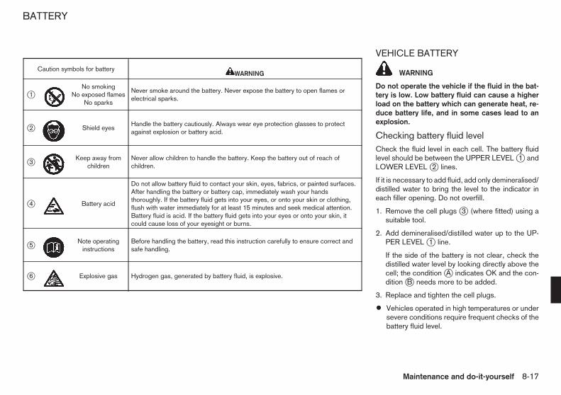
VEHICLE BATTERY
WARNING
Do not operate the vehicle if the fluid in the bat-tery is low. Low battery fluid can cause a higherload on the battery which can generate heat, re-duce battery life, and in some cases lead to anexplosion.
Checking battery fluid levelCheck the fluid level in each cell. The battery fluidlevel should be between the UPPER LEVEL j1 andLOWER LEVEL j2 lines.
If it is necessary to add fluid, add only demineralised/distilled water to bring the level to the indicator ineach filler opening. Do not overfill.
1. Remove the cell plugs j3 (where fitted) using asuitable tool.
2. Add demineralised/distilled water up to the UP-PER LEVEL j1 line.
If the side of the battery is not clear, check thedistilled water level by looking directly above thecell; the condition jA indicates OK and the con-dition jB needs more to be added.
3. Replace and tighten the cell plugs.
• Vehicles operated in high temperatures or undersevere conditions require frequent checks of thebattery fluid level.
Caution symbols for battery m WARNING
j1 mNo smoking
No exposed flamesNo sparks
Never smoke around the battery. Never expose the battery to open flames orelectrical sparks.
j2 m Shield eyesHandle the battery cautiously. Always wear eye protection glasses to protectagainst explosion or battery acid.
j3 mKeep away from
childrenNever allow children to handle the battery. Keep the battery out of reach ofchildren.
j4 m Battery acid
Do not allow battery fluid to contact your skin, eyes, fabrics, or painted surfaces.After handling the battery or battery cap, immediately wash your handsthoroughly. If the battery fluid gets into your eyes, or onto your skin or clothing,flush with water immediately for at least 15 minutes and seek medical attention.Battery fluid is acid. If the battery fluid gets into your eyes or onto your skin, itcould cause loss of your eyesight or burns.
j5 mNote operating
instructionsBefore handling the battery, read this instruction carefully to ensure correct andsafe handling.
j6 m Explosive gas Hydrogen gas, generated by battery fluid, is explosive.
BATTERY
Maintenance and do-it-yourself 8-17

• Keep the battery surface clean and dry. Cleanthe battery with a solution of baking soda andwater.
• Make certain the terminal connections are cleanand securely tightened.
• If the vehicle is not to be used for more than 30days, disconnect the negative (−) battery termi-nal cable to prevent battery discharge.
Jump startingIf jump starting is necessary, see “Jump starting” inthe “6. In case of emergency” section. If the enginedoes not start by jump starting or the battery doesnot charge, the battery may have to be replaced.Contact a NISSAN dealer or qualified workshop forreplacing the battery.
INTEGRATED KEYFOB BATTERY
Battery replacementCAUTION
• Be careful not to allow children to swallow thebattery and removed parts.
NISSAN GREEN PROGRAM
An improperly disposed battery can harm theenvironment. Always confirm local regulationsfor battery disposal.
• When changing batteries, do not let dust or oilget on the components.
• There is danger of explosion if lithium batteryis incorrectly replaced. Replace only with thesame or equivalent type.
To replace the battery:
1. Use an appropriate tool to remove the screw jAand open the lid jB .
2. Replace the battery with a new one.
Recommended battery: CR2016 or equivalent
SDI1808
8-18 Maintenance and do-it-yourself

• Do not touch the internal circuit and electricterminals as doing so could cause a malfunc-tion.
• Make sure that the + side faces the bottom ofthe case jC .
3. Close the lid and install the screw securely.
4. Operate the buttons to check its operation.
See a NISSAN dealer or qualified workshop if youneed assistance for replacement.
INTELLIGENT KEY BATTERY
Battery replacementCAUTION
• Be careful not to allow children to swallow thebattery and removed parts.
NISSAN GREEN PROGRAM
• An improperly disposed battery can harm theenvironment. Always confirm local regulationsfor battery disposal.
• When changing batteries, do not let dust or oilget on the components.
• There is danger of explosion if lithium batteryis incorrectly replaced. Replace only with thesame or equivalent type.
To replace the battery:
1. Slide the locking pin j1 to the unlock position.
2. Remove the Intelligent Key cap as illustrated j2 .
3. Use an appropriate tool to remove the screw j3and open the lid j4 .
4. Replace the battery with a new one.
Recommended battery: CR2032 or equivalent
• Do not touch the internal circuits and electric ter-minals as doing so could cause a malfunction.
• Make sure that the + side faces the bottom of thecase.
See a NISSAN dealer or qualified workshop if youneed assistance for replacement.
SDI2094
Maintenance and do-it-yourself 8-19

ENGINE COMPARTMENT
CAUTION
Never use a fuse of a higher or lower amperagerating than that specified on the fuse box cover.This could damage the electrical system or causea fire.
If any electrical equipment does not operate, checkfor an open fuse.
1. Be sure the ignition switch is in the “OFF” posi-tion.
2. Be sure the headlight switch is in the “OFF”position.
3. Open the engine bonnet.
4. Remove the fuse/fusible link holder cover bypushing the tab j1 and lifting the cover from theright side j2 , then the left side j3 .
Remove the fuse holder cover by removing thetabs j4 on the rear side and front side of the
vehicle while pushing the tabs j5 and pulling allsides of the fuse cover. Then remove the tabs j5and j6 , and lift the fuse holder cover j7 .
5. Locate the fuse that needs to be replaced.
6. Remove the fuse using the fuse puller located inthe passenger compartment fuse box.
7. If the fuse is open jA , replace it with a new fusejB .
If the new fuse also opens, after installing, have theelectrical system checked, and if necessaryrepaired, by a NISSAN dealer or qualified work-shop.
Fusible linksIf any electrical equipment does not operate and thefuses are in good condition, check the fusible linksin the holders j1 , j2 and j3 . If any of these fusiblelinks are melted, replace only with Genuine NISSANparts.
For checking and replacing the fusible links in holderj3 , see a NISSAN dealer or qualified workshop.
SDI2622Z
SDI1753Z
SDI2489Z
FUSES
8-20 Maintenance and do-it-yourself

PASSENGER COMPARTMENTCAUTION
Never use a fuse of a higher or lower amperagerating than that specified on the fuse box cover.This could damage the electrical system or causea fire.
If any electrical equipment does not operate, checkfor an open fuse.
1. Be sure the ignition switch is in the “OFF” posi-tion.
2. Be sure the headlight switch is in the “OFF”position.
3. Remove the fuse box cover.
4. Locate the fuse that needs to be replaced.
5. Remove the fuse using the fuse puller jA (Left-hand drive model) or jB (Right-hand drivemodel).
6. If the fuse is open jA , replace it with a new fusejB .
If the new fuse also opens, after installing, have theelectrical system checked, and if necessaryrepaired, by a NISSAN dealer or qualified work-shop.
HEADLIGHTSFog may temporarily form inside the lens of the exte-rior lights in the rain or in a car wash. A temperaturedifference between the inside and the outside of thelens causes the fog. This is not a malfunction. Iflarge drops of water collect inside the lens, contacta NISSAN dealer or qualified workshop.
Replacing halogen headlight bulbThe halogen headlight is a semi-sealed beam typewhich uses replaceable headlight (halogen) bulbs.They can be replaced from inside the engine com-partment without removing the headlight assembly.
CAUTION
High-pressure halogen gas is sealed inside thebulb. The bulb may break if the glass envelope isscratched or the bulb is dropped.
1. Disconnect the battery negative cable.
SDI2461Z
SDI1753Z
LIGHTS
Maintenance and do-it-yourself 8-21

2. Disconnect the electrical connector j1 from therear end of the bulb.
3. Pull off the rubber cap j2 .
4. Push and turn the retaining pin j3 to loosen it.
5. Remove the headlight bulb. Do not shake or ro-tate the bulb when removing it.
6. Install the new bulb in the reverse order of re-moval.
CAUTION
• When handling the bulb, do not touch theglass envelope.
• Use the same number and wattage as origi-nally installed:Halogen headlight model
High beam bulb: 60W (H4)Low beam bulb: 55W (H4)
• Do not leave the bulb out of the headlightreflector for a long period of time as dust,moisture and smoke may enter the headlightbody and affect the performance of the head-light.
Aiming adjustment is not necessary if only the bulbsare replaced. When aiming adjustment is neces-sary, contact a NISSAN dealer or qualified work-shop.
EXTERIOR LIGHTSItem Wattage (W)Front turn signal light 21Front clearance light 5Front fog light (where fitted) 35Side turn signal light 5Rear combination light
Turn signal 21Stop/Tail light 21/5Rear fog light 21
Reverse light 21High-mounted stop light* 16Number plate light 5
*: See a NISSAN dealer or qualified workshop forreplacement.
INTERIOR LIGHTSItem Wattage (W)Room light 10Luggage compartment light 5
SDI2438
8-22 Maintenance and do-it-yourself

LIGHT LOCATIONS1. Front turn signal light
2. Room light
3. Front fog light (where fitted)
4. Clearance light
5. Headlight
6. Side turn signal light
7. Luggage compartment light
8. High-mounted stop light
9. Stop/tail light
10. Rear fog light*1 or Reverse light*2
11. Number plate light
12. Reverse light*1 or Rear fog light*2
13. Rear turn signal light
14. Room light (where fitted)
*1: Left-Hand Drive (LHD) model
*2: Right-Hand Drive (RHD) model
NDI1244
Maintenance and do-it-yourself 8-23

: REMOVE
: INSTALL
Replacement proceduresAll other lights are either type A, B, C, D or E. Whenreplacing a bulb, first remove the lens and/or cover.
SDI2306
SDI2440Z
Front turn signal light
SDI2441Z
Clearance light
SDI2442
Front fog light (where fitted)
8-24 Maintenance and do-it-yourself

jA : Bolts
SDI2445
Side turn signal light
SDI2446
Rear combination light
SDI2454Z
Number plate light
SDI1845Z
Room light
Maintenance and do-it-yourself 8-25

If you have a flat tyre, see “Flat tyre” in the “6. Incase of emergency” section.
TYRE INFLATION PRESSUREPeriodically check the pressure of the tyres, includ-ing the spare. An incorrect tyre pressure may ad-versely affect tyre life and vehicle handling. The tyrepressure should be checked when tyres are COLD.Tyres are considered COLD after the vehicle hasbeen parked for 3 or more hours, or driven less than1.6 km (1 mile). COLD tyre pressures are shown onthe tyre placard.
Insufficient pressure can lead to an overheating ofthe tyre and subsequent internal damage. At highspeeds, this could result in tread separation andeven bursting of the tyre.
TYPES OF TYRESCAUTION
When changing or replacing tyres, be sure allfour tyres are of the same type (that is, summer,all season or snow) and construction. A NISSANdealer may be able to help you with informationabout tyre type, size, speed rating and availabil-ity.
Replacement tyres may have a lower speed ratingthan the factory equipped tyres, and they may notmatch the potential maximum vehicle speed. Neverexceed the maximum speed rating of the tyre.
All season tyresNISSAN specifies all season tyres on some modelsto provide good performance all year, includingsnowy and icy road conditions. All season tyres areidentified by ALL SEASON and/or M&S on the tyresidewall. Snow tyres have better snow traction thanall season tyres and may be more appropriate insome areas.
Summer tyresNISSAN specifies summer tyres on some models toprovide superior performance on dry roads. Sum-mer tyre performance is substantially reduced insnow and ice. Summer tyres do not have the tyretraction rating M&S on the tyre sidewall.
If you plan to operate your vehicle in snowy or icyconditions, NISSAN recommends the use of snowor all season tyres on all four wheels.
Snow tyresIf snow tyres are needed, it is necessary to selecttyres equivalent in size and load rating to the originalequipment tyres. If you do not, it can adversely af-fect the safety and handling of your vehicle.
Generally, snow tyres have lower speed ratings thanfactory equipped tyres and may not match the po-tential maximum vehicle speed. Never exceed themaximum speed rating of the tyre. If you install snowtyres, they must be the same size, brand, construc-tion and tread pattern on all four wheels.
For additional traction on icy roads, studded tyresmay be used. However, some states and provinces
SDI1724Z
Luggage compartment light
TYRES AND WHEELS
8-26 Maintenance and do-it-yourself

prohibit their use. Check local, state and provinciallaws before installing studded tyres. Skid and trac-tion capabilities of studded snow tyres on wet or drysurfaces may be poorer than that of non-studdedsnow tyres.
TYRE CHAINSUse of tyre chains may be prohibited according tolocation. Check the local laws before installing tyrechains. When installing tyre chains, make sure thatthey are of proper size for the tyres on your vehicleand are installed according to the chain manufactur-er’s instructions.
Use chain tensioners when recommended by thetyre chain manufacturer to ensure a tight fit. Looseend links of the tyre chains must be secured orremoved to prevent the possibility of whipping ac-tion damage to the fenders or underbody. If pos-sible, avoid fully loading your vehicle when usingtyre chains. In addition, drive at a reduced speed.Otherwise, your vehicle may be damaged and/orvehicle handling and performance may be adverselyaffected.
Tyre chains must be installed only on the frontwheels and not on the rear wheels. Do not use thechains on dry roads.
Do not drive with tyre chains on paved roads whichare clear of snow. Driving with chains in such condi-tions can cause damage to the various mechanismsof the vehicle due to some overstress.
TYRE ROTATION
NISSAN recommends that tyres be rotated every10,000 km (6,000 miles). However, the timing fortyre rotation may vary according to your driving hab-its and the road surface conditions. (See “Flat tyre”in the “6. In case of emergency” section for the tyrereplacement.)
WARNING
• After rotating the tyres, adjust the tyre pres-sure.
• Retighten the wheel nuts when the vehiclehas been driven for 1,000 km (600 miles) (alsoin cases of a flat tyre, etc.).
• Incorrect tyre selection, fitting, care, or main-tenance can affect vehicle safety with risk ofaccident and injury. If in doubt, consult aNISSAN dealer or the tyre manufacturer.
TYRE WEAR AND DAMAGE
j1 Wear indicator
j2 Wear indicator location mark
Tyres should be periodically inspected for wear,cracking, bulging or objects caught in the tread. Ifexcessive wear, cracks, bulging or deep cuts arefound, the tyre should be replaced immediately.
The original tyres have a built-in tread wear indica-tor. When the wear indicator is visible, the tyreshould be replaced.
Improper service of a spare tyre may result in seri-ous personal injury. If it is necessary to repair thespare tyre, contact a NISSAN dealer or qualifiedworkshop.
TYRE AGENever use a tyre over six years old, regardless ofwhether it has been used or not.
Tyres degrade with age as well as with the vehicle
SDI1662Z SDI1663Z
Maintenance and do-it-yourself 8-27

usage. Have your tyres checked and balanced oftenby a repair shop or, if you prefer, a NISSAN dealer.
CHANGING TYRES AND WHEELS
WARNING
Do not install a deformed wheel or tyre even if ithas been repaired. Such wheels or tyres couldhave structural damage and could fail withoutwarning.
When replacing a tyre, use the same size, speedrating and load carrying capacity as originallyequipped. (See “Tyres and wheels” in the “9. Tech-nical information” section for recommended typesand sizes of tyres and wheels.) The use of tyresother than those recommended or the mixed use oftyres of different brands, construction (bias, bias-belted, or radial), or tread patterns can adverselyaffect the ride, braking, handling, ground clearance,body-to-tyre clearance, snow chain clearance,speedometer calibration, headlight aim and bumperheight. Some of these effects may lead to accidentsand could result in serious personal injury.
If the wheels are changed for any reason, alwaysreplace with wheels which have the same offsetdimension. Wheels of a different offset could causeearly tyre wear, possibly degraded vehicle handlingcharacteristics and/or interference with the brakediscs/drums. Such interference can lead todecreased braking efficiency and/or early brakepad/shoe wear.
WHEEL BALANCEUnbalanced wheels may affect vehicle handling andtyre life. Even with regular use, wheels can get outof balance. Therefore, they should be balanced asrequired.
SPARE TYRE
Conventional spare tyreA standard tyre (the same size as the road wheels)is supplied with your vehicle.
8-28 Maintenance and do-it-yourself

9 Technical informationTechnical information
Recommended fuel/lubricants and capacities........... 9-2Fuel recommendation ......................................... 9-4Recommended SAE viscosity number................. 9-4Air conditioner system refrigerant and lubricant ... 9-5
Engine ..................................................................... 9-5Tyres and wheels..................................................... 9-6Dimensions.............................................................. 9-6When travelling or registering in another country ...... 9-6Vehicle identification ................................................ 9-7
Vehicle identification label ................................... 9-7Vehicle Identification Number (VIN) plate ............ 9-7
Vehicle Identification Number (chassisnumber).............................................................. 9-7Engine serial number .......................................... 9-7Tyre placard ....................................................... 9-8Air conditioner specification label (wherefitted).................................................................. 9-8
Radio approval number and information ................... 9-8Remote keyless entry system (where fitted)......... 9-8Intelligent Key system (where fitted) .................... 9-8NISSAN Anti-Theft System (NATS)immobilizer ......................................................... 9-11

The following are approximate capacities. The actual refill quantities may be slightly different. When refilling, follow the procedures instructed in the “8. Maintenanceand do-it-yourself” section to determine the proper refill capacity.
Capacity (Approximate) Recommended fuel and lubricantsLitre Imp measure
Fuel 55 12-1/8 gal See “Fuel recommendation” later in this section.Engine oil (Refill) (*1)
HR16DE With oil filter 4.3 3-3/4 qt (Petrol engine)• Genuine NISSAN engine oil (*2)• API grade SL or SM, ILSAC grade GF-3 or GF-4, ACEA A1/B1, A3/B3, A3/B4, A5/B5, C2 or
C3 (*2)(Diesel engine)• Genuine NISSAN engine oil (*2)• ACEA A1/B1 (*2), (*3)• Viscosity SAE 5W-30 (*2)
Without oil filter 4.1 3-5/8 qt
K9K With oil filter 4.4 3-7/8 qt
Without oil filter 4.2 3-3/4 qt
Cooling system (with reservoir)total HR16DE 6.3 5-1/2 qt Genuine NISSAN Engine Coolant or equivalent in its quality (*4)
K9K 6.5 5-3/4 qtreservoir HR16DE 0.7 5/8 qt
K9K 0.4 3/8 qtManual Transmission (MT) gear oil — — Genuine NISSAN gear oil (ETL8997B) 75W-80 or equivalent (*5)Brake and clutch fluid Refill to the proper fluid level accord-
ing to the instructions in the “8.Maintenance and do-it-yourself” sec-tion.
Genuine NISSAN Brake Fluid or equivalent DOT 3 or DOT 4 (*6)
Multi-purpose grease — — NLGI No. 2 (Lithium soap base)Air conditioner system refrigerant — — HFC-134a (R-134a)Air conditioner system lubricants — — NISSAN A/C System Oil Type R (HR16DE engine), Type S (K9K engine) or an exact equivalent
RECOMMENDED FUEL/LUBRICANTS AND CAPACITIES
9-2 Technical information

*1: For additional information, see “Engine oil” in the “8. Maintenance and do-it-yourself” section.
*2: For further details, see “Recommended SAE viscosity number” later in this section.
*3: With the technical performances of oil ACEA A3/B4.
*4: Use Genuine NISSAN Engine Coolant, or equivalent in its quality, in order to avoid possible aluminium corrosion within the engine cooling system caused by the use of non-genuineengine coolant.Note that any repairs for the incidents within the engine cooling system while using non-genuine engine coolant may not be covered by the warranty even if such incidentsoccurred during the warranty period.
*5: If Genuine NISSAN gear oil (ETL8997B) 75W-80 is not available, API GL-4, Viscosity SAE 75W-80 may be used as a temporary replacement. However, use Genuine NISSANgear oil as soon as it is available.
*6: Never mix different types of fluids (DOT3 and DOT4).
Technical information 9-3

FUEL RECOMMENDATION
Petrol engine (model with three-waycatalyst)CAUTION
Do not use leaded petrol. Using leaded petrol willdamage the three-way catalyst.
Use UNLEADED PREMIUM petrol of at least 95octane (RON).
If unleaded premium petrol is not used, UNLEADEDREGULAR petrol with an octane rating of at least 91(RON) may be used at slightly reducedperformance. However, for maximum vehicle per-formance and the best driveability, the use of un-leaded premium petrol is recommended.
Diesel engine*EN590 Diesel fuel of at least 51 cetane must beused.
NOTE
Use only low sulphur diesel.* If two types of diesel fuel are available, use sum-
mer or winter fuel properly according to the fol-lowing temperature conditions.
• Above −7°C (20°F) ... Summer type dieselfuel.
• Below −7°C (20°F) ... Winter type diesel fuel.
If you are in any doubt, please consult a NISSANdealer or qualified workshop.
CAUTION
• Do not use home heating oil, petrol or otheralternate fuels in the diesel engine, this cancause engine damage.
• Do not add petrol or other alternate fuels todiesel fuel.
• Do not use summer fuel at temperatures be-low –7°C (20°F). The cold temperatures willcause wax to form in the fuel. As a result, itmay prevent the engine from runningsmoothly.
RECOMMENDED SAE VISCOSITYNUMBER
Outside Temperature RangeAnticipated Before Next Oil Change
PETROL AND DIESEL ENGINE OIL
mNTI187
Petrol engine oil5W-30 is preferable.
If 5W-30 is not available, select the viscosity, fromthe chart, that is suitable for the outside tem-perature range.
9-4 Technical information
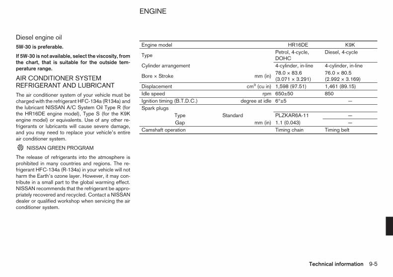
Diesel engine oil5W-30 is preferable.
If 5W-30 is not available, select the viscosity, fromthe chart, that is suitable for the outside tem-perature range.
AIR CONDITIONER SYSTEMREFRIGERANT AND LUBRICANTThe air conditioner system of your vehicle must becharged with the refrigerant HFC-134a (R134a) andthe lubricant NISSAN A/C System Oil Type R (forthe HR16DE engine model), Type S (for the K9Kengine model) or equivalents. Use of any other re-frigerants or lubricants will cause severe damage,and you may need to replace your vehicle’s entireair conditioner system.
NISSAN GREEN PROGRAM
The release of refrigerants into the atmosphere isprohibited in many countries and regions. The re-frigerant HFC-134a (R-134a) in your vehicle will notharm the Earth’s ozone layer. However, it may con-tribute in a small part to the global warming effect.NISSAN recommends that the refrigerant be appro-priately recovered and recycled. Contact a NISSANdealer or qualified workshop when servicing the airconditioner system.
Engine model HR16DE K9K
TypePetrol, 4-cycle,DOHC
Diesel, 4-cycle
Cylinder arrangement 4-cylinder, in-line 4-cylinder, in-line
Bore × Stroke mm (in)78.0 × 83.6(3.071 × 3.291)
76.0 × 80.5(2.992 × 3.169)
Displacement cm3 (cu in) 1,598 (97.51) 1,461 (89.15)Idle speed rpm 650±50 850Ignition timing (B.T.D.C.) degree at idle 6°±5 —Spark plugs
Type Standard PLZKAR6A-11 —Gap mm (in) 1.1 (0.043) —
Camshaft operation Timing chain Timing belt
ENGINE
Technical information 9-5

Tyre size Standard Spare175/70 R14C Conventional
Roadwheel
Size Offset mm(in)
Steel 14 × 5.5JJ 45 (1.77)Aluminium 14 × 5.5J 45 (1.77)
Unit: mm (in)
Overall length 4,400 (173.2)Overall width 1,695 (66.7)Overall height 1,860 (73.2)Front tread 1,490 (58.7)Rear tread 1,510 (59.4)Wheelbase 2,725 (107.3)
When planning to travel in another country or re-gion, find out whether the fuel required for yourvehicle is available in that country or region. Using alow octane rated fuel may cause engine damage.Therefore, be sure that the required fuel is availablewherever you go. For additional information regard-ing recommended fuel, see earlier in this section.
When transferring the registration of your vehicleto another country, state, province or district,contact the appropriate authorities to find out thatthe vehicle complies with the local legal require-ments. In some cases, a vehicle cannot meet thelegal requirements, and it may be necessary tomodify the vehicle to meet local laws and regula-tions. In addition, there may be possibilities that avehicle cannot be adapted in certain areas.
The laws and regulations for motor vehicle emissioncontrol and safety standards vary according to thecountry, state, province or district; therefore, thevehicle specification may differ.
When any vehicles are to be taken into anothercountry, state, province or district, its modifica-tion, transportation, registration, and any otherexpenses which may result, are the responsibil-ity of the user. NISSAN is not responsible for anyinconveniences that may result.
TYRES AND WHEELS DIMENSIONS WHEN TRAVELLING ORREGISTERING IN ANOTHERCOUNTRY
9-6 Technical information

VEHICLE IDENTIFICATION LABEL
The label is attached as shown in the front passen-ger’s side centre pillar.
VEHICLE IDENTIFICATION NUMBER(VIN) PLATE
The vehicle identification number plate j1 is at-tached as shown. This number is the identificationfor your vehicle and is used in the vehicle registra-tion.
VEHICLE IDENTIFICATION NUMBER(chassis number)
The vehicle identification number is stamped asshown.
ENGINE SERIAL NUMBER
The engine serial number is stamped on the engineas shown.
STI0655Z
STI0537Z
STI0656Z
STI0466Z
HR16DE engine
STI0662Z
K9K engine
VEHICLE IDENTIFICATION
Technical information 9-7

TYRE PLACARD
The cold tyre pressures are shown on the tyre plac-ard affixed to the driver’s side centre pillar.
AIR CONDITIONER SPECIFICATIONLABEL (where fitted)
The air conditioner specification label is attached tothe underside of the bonnet as shown.
REMOTE KEYLESS ENTRY SYSTEM(where fitted)
INTELLIGENT KEY SYSTEM(where fitted)
STI0657Z
STI0658Z
STI0527Z STI0663
RADIO APPROVAL NUMBER ANDINFORMATION
9-8 Technical information
STI0664 STI0665 STI0666
Technical information 9-9

STI0667 STI0668 STI0669
9-10 Technical information

Intelligent Key system (where fitted)
NISSAN ANTI-THEFT SYSTEM (NATS)IMMOBILIZER
STI0670 STI0671
Model without Intelligent Key system
STI0672
Model with Intelligent Key system
Technical information 9-11

NOTE
9-12 Technical information

NOTE
Technical information 9-13

NOTE
9-14 Technical information

NOTE
Technical information 9-15

NOTE
9-16 Technical information
NOTE
Technical information 9-17

NOTE
9-18 Technical information
10 Index
A
Adjusting time ..................................................................... 2-27Air cleaner filter ................................................................... 8-14Air conditioner– Air conditioner specification label ..................................... 9-8– Air conditioner system refrigerant and lubricant ................ 9-5– Heater and air conditioner ................................................ 4-4– Manual air conditioner ..................................................... 4-5– Servicing air conditioner .................................................. 4-7Antenna ................................................................................ 4-9Anti-lock Braking System (ABS) .......................................... 5-15Ashtray ................................................................................ 2-28Audible reminders ............................................................... 2-16Audible reminders, warning/indicator lights .......................... 2-10Audio operation precautions .................................................. 4-8Audio system ........................................................................ 4-8
B
Back door ........................................................................... 3-20– Locking or unlocking back door ..................................... 3-20Battery ....................................................................... 5-17, 8-17– Battery saver system ................................... 2-20, 2-34, 2-35– Integrated keyfob battery ............................................... 8-18– Intelligent key battery ..................................................... 8-19Before starting engine ........................................................... 5-2Bleeding fuel system ........................................................... 8-10Blocking wheels .................................................................... 6-3Bonnet ................................................................................ 3-19
Brake– Anti-lock Braking System (ABS) .................................... 5-15– Brake booster ............................................................... 8-13– Brake fluid ..................................................................... 8-13– Brake precautions ......................................................... 5-15– Brake system ................................................................ 5-15– Brakes .......................................................................... 8-12– Checking footbrake pedal .............................................. 8-12– Checking parking brake ................................................. 8-12– Hand brake ................................................................... 3-24– Parking brake ................................................................ 3-24– Trailer brakes ................................................................ 5-13
C
Car phone or CB radio ........................................................ 4-16Card holder ......................................................................... 2-31Care when driving ................................................................. 5-4CD Player/LW-MW-FM radio .............................................. 4-10Centre vents ......................................................................... 4-4Changing– Changing engine coolant ................................................. 8-6– Changing engine oil and oil filter ...................................... 8-7– Changing tyres and wheels ........................................... 8-28– Checking engine oil level ................................................. 8-6Checking– Checking bulbs ............................................................. 2-10– Checking engine coolant level ......................................... 8-5– Checking engine oil level ................................................. 8-6– Checking footbrake pedal .............................................. 8-12– Checking parking brake ................................................. 8-12
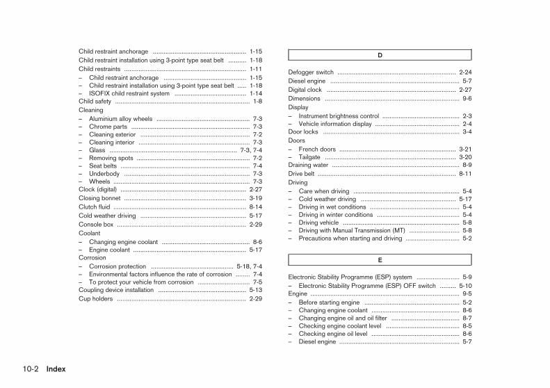
Child restraint anchorage .................................................... 1-15Child restraint installation using 3-point type seat belt .......... 1-18Child restraints .................................................................... 1-11– Child restraint anchorage .............................................. 1-15– Child restraint installation using 3-point type seat belt ..... 1-18– ISOFIX child restraint system ........................................ 1-14Child safety ........................................................................... 1-8Cleaning– Aluminium alloy wheels .................................................... 7-3– Chrome parts .................................................................. 7-3– Cleaning exterior ............................................................. 7-2– Cleaning interior .............................................................. 7-3– Glass ....................................................................... 7-3, 7-4– Removing spots ............................................................... 7-2– Seat belts ........................................................................ 7-4– Underbody ...................................................................... 7-3– Wheels ............................................................................ 7-3Clock (digital) ...................................................................... 2-27Closing bonnet .................................................................... 3-19Clutch fluid .......................................................................... 8-14Cold weather driving ........................................................... 5-17Console box ........................................................................ 2-29Coolant– Changing engine coolant ................................................. 8-6– Engine coolant ............................................................... 5-17Corrosion– Corrosion protection .............................................. 5-18, 7-4– Environmental factors influence the rate of corrosion ........ 7-4– To protect your vehicle from corrosion ............................. 7-5Coupling device installation ................................................. 5-13Cup holders ........................................................................ 2-29
D
Defogger switch .................................................................. 2-24Diesel engine ........................................................................ 5-7Digital clock ........................................................................ 2-27Dimensions ........................................................................... 9-6Display– Instrument brightness control ........................................... 2-3– Vehicle information display ............................................... 2-4Door locks ............................................................................ 3-4Doors– French doors ................................................................. 3-21– Tailgate ......................................................................... 3-20Draining water ....................................................................... 8-9Drive belt ............................................................................. 8-11Driving– Care when driving ........................................................... 5-4– Cold weather driving ..................................................... 5-17– Driving in wet conditions .................................................. 5-4– Driving in winter conditions .............................................. 5-4– Driving vehicle ................................................................. 5-8– Driving with Manual Transmission (MT) ............................ 5-8– Precautions when starting and driving .............................. 5-2
E
Electronic Stability Programme (ESP) system ........................ 5-9– Electronic Stability Programme (ESP) OFF switch ......... 5-10Engine ................................................................................... 9-5– Before starting engine ..................................................... 5-2– Changing engine coolant ................................................. 8-6– Changing engine oil and oil filter ...................................... 8-7– Checking engine coolant level ......................................... 8-5– Checking engine oil level ................................................. 8-6– Diesel engine ................................................................... 5-7
10-2 Index

– Engine cold start period ................................................... 5-4– Engine compartment ............................................ 0-11, 8-20– Engine compartment check locations ............................... 8-5– Engine coolant ............................................................... 5-17– Engine cooling system ..................................................... 8-5– Engine oil ........................................................................ 8-6– Engine overheat ............................................................... 6-7– Fuel filter ......................................................................... 8-9– Petrol engine ................................................................... 5-6– Spark plugs ................................................................... 8-11– Starting engine ................................................................ 5-6Engine oil level information display ......................................... 2-9Exhaust gas ........................................................................... 5-2Explanation of general maintenance items .............................. 8-2Exterior lights ...................................................................... 8-22
F
Flat tyre ................................................................................. 6-2Floor mats ............................................................................. 7-4Fluid– Brake fluid ..................................................................... 8-13– Clutch fluid .................................................................... 8-14– Window washer fluid ..................................................... 8-16Fog light– Front fog light ................................................................ 2-21– Rear fog light ................................................................. 2-21French doors ...................................................................... 3-21Front door ............................................................................. 3-5Fuel– Fuel filler cap ................................................................. 3-22– Fuel filler lid ................................................................... 3-22– Fuel filter ......................................................................... 8-9– Fuel gauge ...................................................................... 2-2– Fuel recommendation ...................................................... 9-4– Opening fuel filler lid ...................................................... 3-22
– Recommended fuel/lubricants and capacities .................. 9-2Fuses .................................................................................. 8-20
G
Gauges– Fuel gauge ...................................................................... 2-2– Instrument brightness control ........................................... 2-3– Meters and gauges .......................................................... 2-2General maintenance ............................................................ 8-2Glove box ............................................................................ 2-28
H
Hand brake ......................................................................... 3-24Hazard indicator flasher switch ............................................ 2-24Head restraint– Adjustment ...................................................................... 1-6Headlight– Headlight switch ............................................................ 2-17– Headlights ..................................................................... 8-21– Manual aiming control .................................................... 2-18Headlight aiming control ...................................................... 2-18Heater and air conditioner ..................................................... 4-4Horn ................................................................................... 2-25How to read the displayed lines ............................................. 4-2
I
Ignition switch ....................................................................... 5-4Ignition switch cap ................................................................ 3-4Immobilizer ............................................................................ 3-2Indicator lights ............................................................ 2-10, 2-14
Index 10-3

Indicators for maintenance ..................................................... 2-6Indicators for operation .......................................................... 2-4Injured persons ..................................................................... 1-9Installing spare tyre ............................................................... 6-5Instrument panel .................................................................... 0-8– LHD models .................................................................... 0-8– RHD models .................................................................... 0-9Integrated keyfob .................................................................. 3-2Integrated keyfob battery ..................................................... 8-18Intelligent key battery ........................................................... 8-19Intelligent Key system ............................................ 3-10, 5-4, 9-9– Intelligent Key .................................................................. 3-3– Intelligent Key operating range ....................................... 3-11– Troubleshooting guide ................................................... 3-16Interior lights .............................................................. 2-34, 8-22– Room light ..................................................................... 2-34ISOFIX child restraint system .............................................. 1-14
J
Jump starting ......................................................................... 6-6
K
Key– Ignition switch cap ........................................................... 3-4– Intelligent Key .................................................................. 3-3– Intelligent key battery ..................................................... 8-19– Intelligent Key operating range ....................................... 3-11– Intelligent Key system ...................................... 3-10, 5-4, 9-9– Key positions ................................................................... 5-6– Keys ................................................................................ 3-2– Locking with key .............................................................. 3-5– Mechanical key ................................................................ 3-4– NISSAN Anti-Theft System (NATS) key ........................... 3-2
– Remote keyless entry system .................................... 3-8, 9-8– Using Intelligent Key system .......................................... 3-12– Using remote keyless entry system .................................. 3-8
L
Light– Exterior lights ................................................................. 8-22– Fog light switch ............................................................. 2-21– Headlight switch ............................................................ 2-17– Headlights ..................................................................... 8-21– Indicator lights ...................................................... 2-10, 2-14– Interior lights ........................................................ 2-34, 8-22– Light locations ............................................................... 8-23– Lights ............................................................................ 8-21– Luggage compartment light ........................................... 2-34– Trailer direction indicator light ........................................ 2-10– Warning lights ...................................................... 2-10, 2-11Lock– Anti-lock Braking System (ABS) .................................... 5-15– Door locks ....................................................................... 3-4– Locking with inside lock knob .......................................... 3-5– Locking with key .............................................................. 3-5– Power door lock switch ................................................... 3-6– Steering lock ................................................................... 5-6– Super Lock System ......................................................... 3-4Luggage– Loading luggage .............................................................. 5-4– Luggage compartment light ........................................... 2-34Luggage compartment light ................................................. 2-34– Battery saver system ..................................................... 2-35Luggage hooks ................................................................... 2-32
10-4 Index
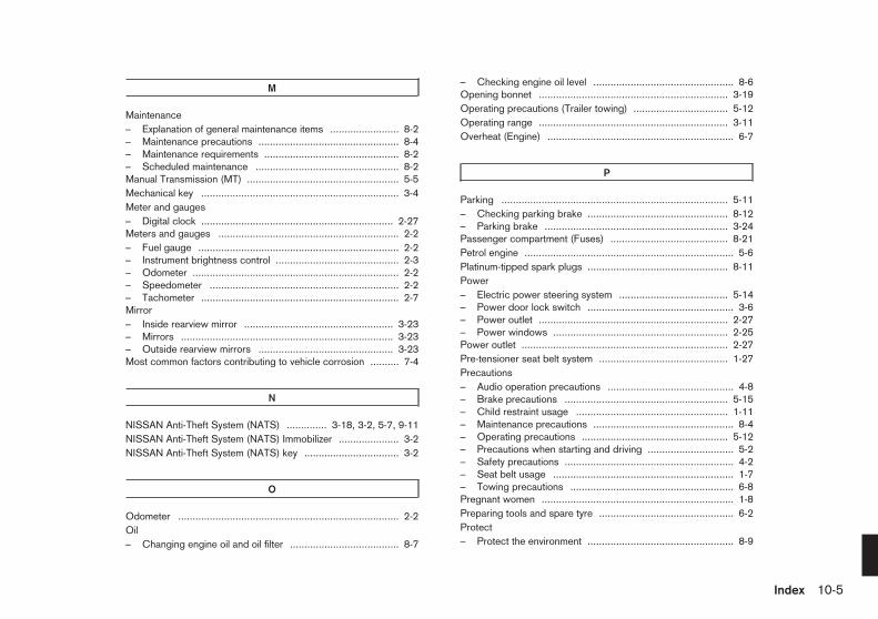
M
Maintenance– Explanation of general maintenance items ........................ 8-2– Maintenance precautions ................................................. 8-4– Maintenance requirements ............................................... 8-2– Scheduled maintenance .................................................. 8-2Manual Transmission (MT) ..................................................... 5-5Mechanical key ..................................................................... 3-4Meter and gauges– Digital clock ................................................................... 2-27Meters and gauges ............................................................... 2-2– Fuel gauge ...................................................................... 2-2– Instrument brightness control ........................................... 2-3– Odometer ........................................................................ 2-2– Speedometer .................................................................. 2-2– Tachometer ..................................................................... 2-7Mirror– Inside rearview mirror .................................................... 3-23– Mirrors .......................................................................... 3-23– Outside rearview mirrors ............................................... 3-23Most common factors contributing to vehicle corrosion .......... 7-4
N
NISSAN Anti-Theft System (NATS) .............. 3-18, 3-2, 5-7, 9-11NISSAN Anti-Theft System (NATS) Immobilizer ..................... 3-2NISSAN Anti-Theft System (NATS) key ................................. 3-2
O
Odometer ............................................................................. 2-2Oil– Changing engine oil and oil filter ...................................... 8-7
– Checking engine oil level ................................................. 8-6Opening bonnet .................................................................. 3-19Operating precautions (Trailer towing) ................................. 5-12Operating range .................................................................. 3-11Overheat (Engine) ................................................................. 6-7
P
Parking ............................................................................... 5-11– Checking parking brake ................................................. 8-12– Parking brake ................................................................ 3-24Passenger compartment (Fuses) ......................................... 8-21Petrol engine ......................................................................... 5-6Platinum-tipped spark plugs ................................................. 8-11Power– Electric power steering system ...................................... 5-14– Power door lock switch ................................................... 3-6– Power outlet .................................................................. 2-27– Power windows ............................................................. 2-25Power outlet ........................................................................ 2-27Pre-tensioner seat belt system ............................................. 1-27Precautions– Audio operation precautions ............................................ 4-8– Brake precautions ......................................................... 5-15– Child restraint usage ..................................................... 1-11– Maintenance precautions ................................................. 8-4– Operating precautions ................................................... 5-12– Precautions when starting and driving .............................. 5-2– Safety precautions ........................................................... 4-2– Seat belt usage ............................................................... 1-7– Towing precautions ......................................................... 6-8Pregnant women ................................................................... 1-8Preparing tools and spare tyre ............................................... 6-2Protect– Protect the environment ................................................... 8-9
Index 10-5

Protect environment .............................................................. 8-9Push starting ......................................................................... 6-7
R
Radio– Car phone or CB radio .................................................. 4-16– CD Player/LW-MW-FM radio ........................................ 4-10Rear– Rear window wiper and washer operation ...................... 2-23Rear cooler ........................................................................... 4-7Rear vents ............................................................................. 4-4Rear view monitor ................................................................. 4-2Rear window wiper blade .................................................... 8-16Recommended fuel/lubricants and capacities ........................ 9-2Recommended SAE viscosity number ................................... 9-4Remote keyless entry system .......................................... 3-8, 9-8Removing tyre ....................................................................... 6-3Repair and replacement procedure ...................................... 1-27Room light ........................................................................... 2-34– Battery saver system ..................................................... 2-34Running-in schedule .............................................................. 5-2
S
Safety– Child safety ..................................................................... 1-8– Head restraints adjustment .............................................. 1-6– Safety chains (Trailer towing) ......................................... 5-13Scheduled maintenance ........................................................ 8-2Seat– Front seats – Adjustment ................................................. 1-2– Head restraints adjustment .............................................. 1-6– Seat belts ........................................................................ 7-4
– Seats .............................................................................. 1-2– Second row seats ........................................................... 1-3– Third row seats ............................................................... 1-5Seat belt ............................................................................... 1-7– Child safety ..................................................................... 1-8– Injured persons ............................................................... 1-9– Precautions on seat belt usage ........................................ 1-7– Pregnant women ............................................................. 1-8– Seat belt warning light ................................................... 2-10– Seat belts ........................................................................ 7-4– Three-point type seat belts ............................................... 1-9Second row seats ................................................................. 1-3Security system ................................................................... 3-18– NISSAN Anti-Theft System (NATS) ............................... 3-18Servicing air conditioner ........................................................ 4-7Side vents ............................................................................. 4-4Sliding door ........................................................................... 3-7Spare tyre .................................................................... 6-2, 8-28Spark plugs ......................................................................... 8-11Special winter equipment .................................................... 5-17Speedometer ........................................................................ 2-2Starting– Before starting engine ..................................................... 5-2– Jump starting ................................................................... 6-6– NISSAN Anti-Theft System (NATS) ................................. 5-7– Precautions when starting and driving .............................. 5-2– Push starting ................................................................... 6-7– Starting engine ................................................................ 5-6Steering– Electric power steering system ...................................... 5-14– Steering lock ................................................................... 5-6– Steering wheel .............................................................. 3-23– Tilt operation ................................................................. 3-23Stopping vehicle .................................................................... 6-2Storage ............................................................................... 2-28– Card holder ................................................................... 2-31– Console box .................................................................. 2-29
10-6 Index

– Cup holders .................................................................. 2-29– Glove box ...................................................................... 2-28– Luggage hooks ............................................................. 2-32– Partition ......................................................................... 2-33– Ticket holder ................................................................. 2-31– Tonneau cover ............................................................... 2-32– Tray ............................................................................... 2-28– Under-seat tray .............................................................. 2-29– Utility hook .................................................................... 2-31Stowing damaged tyre and tools ............................................ 6-5Sun visors ........................................................................... 2-33Super Lock System ............................................................... 3-4Supplemental air bag systems ............................................. 1-25Supplemental Restraint System (air bag system)– Air bag system .............................................................. 1-21Switch– Defogger switch ............................................................ 2-24– Electronic Stability Programme (ESP) system .................. 5-9– Fog light switch ............................................................. 2-21– Front fog light switch ..................................................... 2-21– Hazard indicator flasher switch ...................................... 2-24– Ignition switch ................................................................. 5-4– Main lighting switch ....................................................... 2-17– Power door lock switch ................................................... 3-6– Rear fog light switch ...................................................... 2-21– Turn signal switch .......................................................... 2-21– Windscreen wiper and washer switch ............................ 2-22– Wiper and washer switch .............................................. 2-22
T
Tachometer ........................................................................... 2-7Tailgate ............................................................................... 3-20Third row seats ..................................................................... 1-5Three-point type seat belts .................................................... 1-9Three-way catalyst ................................................................. 5-3
Ticket holder ....................................................................... 2-31Tonneau cover .................................................................... 2-32Towing– Towing precautions ......................................................... 6-8– Towing recommended by NISSAN .................................. 6-9– Towing your vehicle ......................................................... 6-8– Trailer towing ................................................................ 5-12– Trailer towing brakes ..................................................... 5-13– Trailer towing detection ................................................. 5-13Transmission– Driving with Manual Transmission (MT) ............................ 5-8– Manual Transmission (MT) ............................................... 5-5Trip computer ........................................................................ 2-6Turn signal switch ............................................................... 2-21Tyre– Changing spare tyre ........................................................ 6-2– Changing tyres and wheels ........................................... 8-28– Flat tyre ........................................................................... 6-2– Installing spare tyre .......................................................... 6-5– Removing tyre ................................................................. 6-3– Spare tyre ..................................................................... 8-28– Stowing damaged tyre and tools ...................................... 6-5– Types of tyres ................................................................ 8-26– Tyre age ........................................................................ 8-27– Tyre chains .................................................................... 8-27– Tyre equipment .............................................................. 5-17– Tyre inflation pressure ................................................... 8-26– Tyre placard .................................................................... 9-8– Tyre pressure ................................................................ 5-12– Tyre rotation .................................................................. 8-27– Tyre wear and damage .................................................. 8-27– Tyres and wheels .......................................................... 8-26Tyre placard .......................................................................... 9-8
Index 10-7

U
Using remote keyless entry function ..................................... 3-13Using remote keyless entry system ........................................ 3-8Utility hook .......................................................................... 2-31
V
Vehicle battery .................................................................... 8-17Vehicle identification .............................................................. 9-7– Vehicle identification label ................................................ 9-7– Vehicle Identification Number (chassis number) ............... 9-7– Vehicle Identification Number (VIN) plate ......................... 9-7Vehicle information display .................................................... 2-4Vehicle security ................................................................... 5-16Vents .................................................................................... 4-4
W
Warning– Warning lights ............................................................... 2-11Warning lights and audible reminders .................................. 3-15Warning/indicator lights and audible reminders .................... 2-10Warnings and alerts .............................................................. 2-5Washing ............................................................................... 7-2Waxing .................................................................................. 7-2Wheel– Aluminium alloy wheels .................................................... 7-3– Blocking wheels .............................................................. 6-3– Cleaning wheels .............................................................. 7-3Wheel balance .................................................................... 8-28When travelling or registering in another country .................... 9-6Where to go for service ......................................................... 8-2Window washer fluid ........................................................... 8-16
Windows ............................................................................. 2-25– Manual windows ............................................................ 2-25– Power windows ............................................................. 2-25– Sliding windows ............................................................ 2-25Windscreen wiper and washer switch ................................. 2-22Windscreen wiper blades .................................................... 8-15Wiper– Rear window wiper and washer operation ...................... 2-23– Rear window wiper blade .............................................. 8-16– Windscreen wiper and washer switch ............................ 2-22– Windscreen wiper blades .............................................. 8-15– Wiper and washer switch .............................................. 2-22– Wiper blades ................................................................. 8-15
10-8 Index

RECOMMENDED FUEL
Petrol engine (model with three-waycatalyst)CAUTION
Do not use leaded petrol. Using leaded petrol willdamage the three-way catalyst.
Use UNLEADED PREMIUM petrol of at least 95octane (RON).
If unleaded premium petrol is not used, UNLEADEDREGULAR petrol with an octane rating of at least 91(RON) may be used at slightly reducedperformance. However, for maximum vehicle per-formance and the best driveability, the use of un-leaded premium petrol is recommended.
Diesel engine*EN590 Diesel fuel of at least 51 cetane must beused.
NOTE
Use only low sulphur diesel.* If two types of diesel fuel are available, use sum-
mer or winter fuel properly according to the fol-lowing temperature conditions.
• Above −7°C (20°F) ... Summer type dieselfuel.
• Below −7°C (20°F) ... Winter type diesel fuel.
CAUTION
• Do not use home heating oil, petrol or otheralternate fuels in the diesel engine, this cancause engine damage.
• Do not add petrol or other alternate fuels todiesel fuel.
• Do not use summer fuel at temperatures be-low −7°C (20°F). Cold temperatures will causewax to form in the fuel and may prevent theengine from running smoothly.
RECOMMENDED ENGINE OILSee “Recommended fuel/lubricants and capacities”in the “9. Technical information” section.
Petrol engine
• Genuine NISSAN engine oil
• API grade: SL or SM
• ILSAC grade: GF-3 or GF-4
• ACEA A1/B1, A3/B3, A3/B4, A5/B5, C2 or C3
Diesel engine
• Genuine NISSAN engine oil
• ACEA A1/B1*
• Viscosity SAE 5W-30
* With the technical performances of oil ACEA A3/B4
TYRE COLD PRESSURESee the tyre placard affixed to the driver’s sidecentre pillar.
PETROL STATION INFORMATION

ENVIRONMENTAL CONCERNNISSAN GREEN PROGRAM
Today, the efforts made by NISSAN to fulfil ourresponsibilities to protect and sustain the environ-ment are far-reaching. Within NISSAN, we promotethe highest levels of practice in every region and inevery area of operations.
COMPLIANCE AT EVERY STEPNISSAN focuses on ensuring that end of life vehiclecomponents are reused, recycled or recovered asthermal energy, and guarantees compliance with EUlegislation (the End of Life Vehicle Directive).
WE BUILD OUR VEHICLES WITHRECYCLING IN MINDReducing landfill waste, emissions, conserving natu-ral resources, and enhancing recycling activities areemphasised daily in our manufacturing, sales andservice operations and in the disposal of end of lifevehicles (ELV).
Design phaseTo reduce environmental impact we have developedyour NISSAN vehicle to be 95% recyclable. Wemark the components to facilitate dismantling, recy-cling and to reduce hazardous substances. Wecarefully verify and control substances of concern.We have already reduced to a minimum the cad-mium, mercury and lead in your NISSAN vehicle.NISSAN includes recycled material in your vehicleand looks for opportunities to increase the percent-age of recycled materials used.
Manufacturing phaseNISSAN plants based in the UK and Spain alreadyachieve a recycling rate of over 90% and are look-ing for further improvements. The UK plant installed8 windmills to cut carbon dioxide emissions at powerplants by more than 3,000 tonnes per year. Sincethe end of March 2007, NMISA (Spain) uses a solarpanel water heating system to save energy. This willgenerate 33% of the energy consumed in the bathsduring the painting of your vehicle.
Production and distribution phaseUsing resources efficiently to reduce the amount ofwaste generated during the production and distribu-tion stage. NISSAN promotes activities based onReducing, Reusing, and Recycling materials when-ever possible. The NISSAN GREEN PROGRAM2010 (NGP2010) is our midterm environmental ac-tion plan defining our goals for achieving a 100%recycling rate for operations in Japan and globally.
Use and service phaseNISSAN dealers are our window to you, our cus-tomer. In order to meet your expectations they pro-vide not only high quality services but are also envi-ronmentally responsible. NISSAN promotes activi-ties to recycle the waste generated as a result ofservice centre activities.
Disposal phaseRecycle your end of life vehicle or its components.When your NISSAN reaches the end of its life, andis no longer suitable for daily use, it still has value.
You can help prevent waste affecting the environ-ment by bringing your NISSAN to be recycled at ourcollection networks in your area. Our collection net-works guarantee no cost for the treatment of yourELV. For further information on how and where todispose of your ELV refer to your local NISSANdealer or consult: www.nissan.eu.
PROTECT THE ENVIRONMENTWHEN DRIVINGYour driving behaviour has significant impact on fueleconomy and the environment. Follow the tips be-low for better fuel-efficiency, better driving habits,and to be environmentally friendly by reducing emis-sions:
Defensive drivingAnticipating traffic conditions and acting accordinglyreduces fuel consumption, helping to protect of ournatural environment. Take your foot off the accelera-tor while approaching traffic lights and avoid lastminute braking when the light turns red.Avoid speeding, harsh acceleration, and strongbraking. The gain in time does not offset pollution ofthe environment. Try to maintain speed when drivinguphill to reduce fuel consumption and pollution.Maintain speed or allow the vehicle to go slowerwhere traffic allows.
Close windows when drivingDriving with a window open at 100 km/h (62 MPH)increases fuel consumption by up to 4%. Drivingwith the windows closed allows for better fueleconomy.
ENVIRONMENT (End of LifeVehicles)

Use the roof rack only when necessaryOnly install the roof luggage system when you reallyneed it, otherwise put it inside the vehicle or store itin your garage. Do not drive around with an emptyroof rack, kayak holder, or ski rack, this will reduceyour aerodynamic drag significantly.
Optimise the use of air conditioningThe air conditioning system has a positive effect ondriving and vehicle safety through comfort coolingand dehumidifying, drivers are more alert and havebetter visibility when window demisting/defoggingbecomes necessary. However, use of the air condi-tioning system will increase fuel consumption sub-stantially in an urban environment. Optimise the useof air conditioning by using the vents as much aspossible.
Use the parking brake on slopesUse the parking brake when holding your vehicle ona slope. Avoid using the clutch to hold your vehicleas this leads to unnecessary fuel consumption andwear.
Maintain a safe distanceAnticipate traffic conditions for a smoother drive andto assure comfort and safety during your trip. Driveand maintain a safe distance from other vehicleswhile in traffic. This will help reduce fuel consump-tion as you will not be constantly tapping yourbrakes.
Check your tyre pressureLow tyre pressure increases fuel consumption aswell as the use of non-recommended tyres. Correcttyre pressure will maximise the grip of your vehicleand optimise fuel consumption.
Have your car serviced regularlyRegular service allows you to run your vehicle inoptimal condition and with the best fuel efficiency.Have your vehicle serviced by your NISSAN dealeror a qualified workshop to ensure that it is main-tained to its original standard.
• In case of emergency ... 6-2
(Flat tyre, engine will not start, overheating,towing)
• How to start the engine ... 5-2
• How to read the meters and gauges ... 2-2
• Maintenance and do-it-yourself ... 8-2
• Technical information ... 9-2
QUICK REFERENCE


SECURITY INFORMATIONAs owner of this vehicle important codes havebeen supplied to you that may be required byyour NISSAN dealer to duplicate keys or re-pair the radio.
Please fill in the allocated areas or attach stick-er(s) if available. Remove this page and keepit in a safe place, not in the vehicle.
When selling your vehicle, we kindly requestyou to hand over this page to the buyer.
SECURITY INFORMATION
Radio security code(where fitted)
Key number
Wheel lock key code(where fitted)
Remove this page from the manual and keep it in a safe place, not in the vehicle.
When selling your vehicle, we kindly request you to hand over this page to the buyer.

Publication No.: OM10E-0M20E0E