nfpa 54 update - npga exponpgaexpo.com/files/215_cabot_nfpa54_update.pdf · 1.1.1 sample deleted...
TRANSCRIPT
NFPA 54 UPDATE
Paul Cabot
American Gas Association
• Summary Listing
• Schedule
• Revisions
– Definitions/General
– Piping
– Appliances and Appliance Installation
– Venting
PRESENTATION TOPICS
2015 Edition Revision
Status
• ANSI Approval – 8/14
• Publication – 9/14
1.1.1 Sample deleted text. 1.1.2 Sample added text.
Presentation Slide Format
Strikethrough denotes deleted text
Underlined text is what is new/added text
NFGC / IFGC Identifies Code(s) Impacted by Change
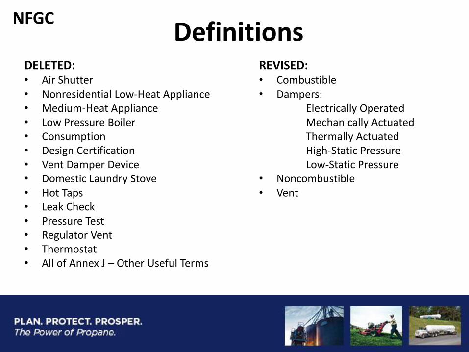
REVISED: • Combustible • Dampers: Electrically Operated Mechanically Actuated Thermally Actuated High-Static Pressure Low-Static Pressure • Noncombustible • Vent
Definitions DELETED: • Air Shutter • Nonresidential Low-Heat Appliance • Medium-Heat Appliance • Low Pressure Boiler • Consumption • Design Certification • Vent Damper Device • Domestic Laundry Stove • Hot Taps • Leak Check • Pressure Test • Regulator Vent • Thermostat • All of Annex J – Other Useful Terms
NFGC
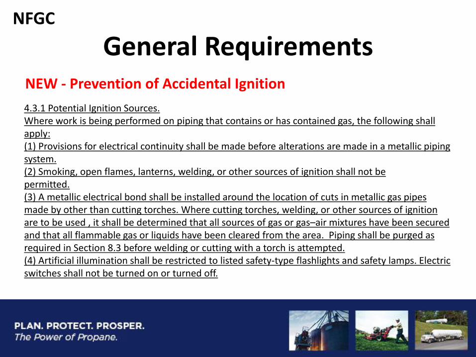
General Requirements NEW - Prevention of Accidental Ignition
4.3.1 Potential Ignition Sources. Where work is being performed on piping that contains or has contained gas, the following shall apply: (1) Provisions for electrical continuity shall be made before alterations are made in a metallic piping system. (2) Smoking, open flames, lanterns, welding, or other sources of ignition shall not be permitted. (3) A metallic electrical bond shall be installed around the location of cuts in metallic gas pipes made by other than cutting torches. Where cutting torches, welding, or other sources of ignition are to be used , it shall be determined that all sources of gas or gas–air mixtures have been secured and that all flammable gas or liquids have been cleared from the area. Piping shall be purged as required in Section 8.3 before welding or cutting with a torch is attempted. (4) Artificial illumination shall be restricted to listed safety-type flashlights and safety lamps. Electric switches shall not be turned on or turned off.
NFGC
Piping System Design
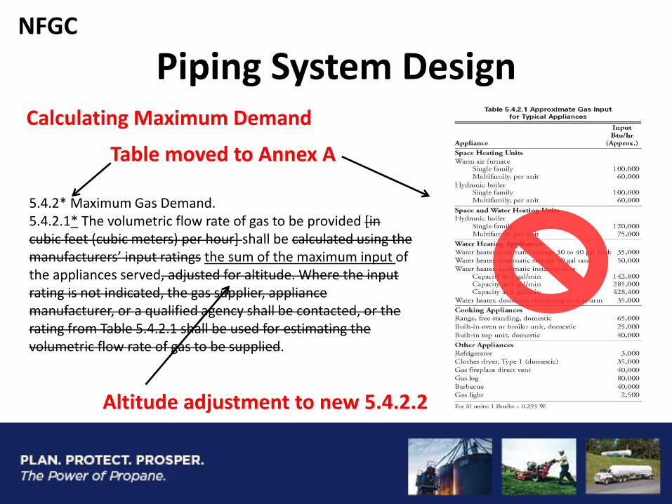
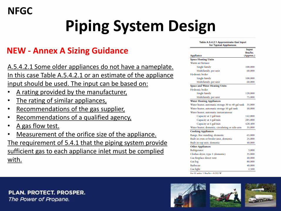
5.4.2* Maximum Gas Demand. 5.4.2.1* The volumetric flow rate of gas to be provided [in cubic feet (cubic meters) per hour] shall be calculated using the manufacturers’ input ratings the sum of the maximum input of the appliances served, adjusted for altitude. Where the input rating is not indicated, the gas supplier, appliance manufacturer, or a qualified agency shall be contacted, or the rating from Table 5.4.2.1 shall be used for estimating the volumetric flow rate of gas to be supplied.
Calculating Maximum Demand
Table moved to Annex A
Altitude adjustment to new 5.4.2.2
NFGC
Piping System Design
NEW - Annex A Sizing Guidance
A.5.4.2.1 Some older appliances do not have a nameplate. In this case Table A.5.4.2.1 or an estimate of the appliance input should be used. The input can be based on: • A rating provided by the manufacturer, • The rating of similar appliances, • Recommendations of the gas supplier, • Recommendations of a qualified agency, • A gas flow test. • Measurement of the orifice size of the appliance. The requirement of 5.4.1 that the piping system provide sufficient gas to each appliance inlet must be complied with.
NFGC
Piping Materials
5.6.4.1.3 Polyvinyl chloride (PVC) and cholorinated polyvinyl chloride (CPVC) plastic pipe, tubing, and fittings shall not be used to supply fuel gas.
NEW- Prohibition on PVC & CPVC for fuel gas piping
NFGC / IFGC
Piping System Design
REVISED - Fittings
5.6.8.4 Metallic Pipe Fittings. Metallic fittings shall comply with the following: (1) Threaded fittings in sizes larger than 4 in. (100 mm) shall not be used unless acceptable to the authority having jurisdiction .
AHJ approval dropped
NFGC / IFGC
Piping System Design
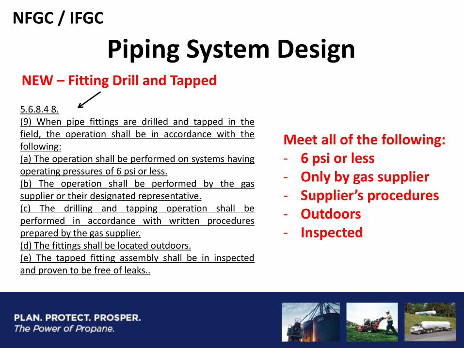
5.6.8.4 8. (9) When pipe fittings are drilled and tapped in the field, the operation shall be in accordance with the following: (a) The operation shall be performed on systems having operating pressures of 6 psi or less. (b) The operation shall be performed by the gas supplier or their designated representative. (c) The drilling and tapping operation shall be performed in accordance with written procedures prepared by the gas supplier. (d) The fittings shall be located outdoors. (e) The tapped fitting assembly shall be in inspected and proven to be free of leaks..
NEW – Fitting Drill and Tapped
Meet all of the following: - 6 psi or less - Only by gas supplier - Supplier’s procedures - Outdoors - Inspected
NFGC / IFGC
Piping Materials
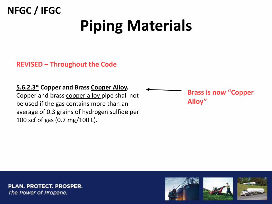
REVISED – Throughout the Code
5.6.2.3* Copper and Brass Copper Alloy. Copper and brass copper alloy pipe shall not be used if the gas contains more than an average of 0.3 grains of hydrogen sulfide per 100 scf of gas (0.7 mg/100 L).
Brass is now “Copper Alloy”
NFGC / IFGC
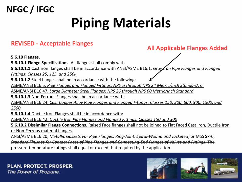
Piping Materials REVISED - Acceptable Flanges
5.6.10 Flanges. 5.6.10.1 Flange Specifications. All flanges shall comply with 5.6.10.1.1 Cast iron flanges shall be in accordance with ANSI/ASME B16.1, Gray Iron Pipe Flanges and Flanged Fittings: Classes 25, 125, and 250,. 5.6.10.1.2 Steel flanges shall be in accordance with the following: ASME/ANSI B16.5, Pipe Flanges and Flanged Fittings: NPS ½ through NPS 24 Metric/Inch Standard, or ASME/ANSI B16.47, Large Diameter Steel Flanges: NPS 26 through NPS 60 Metric/Inch Standard 5.6.10.1.3 Non-Ferrous Flanges shall be in accordance with: ASME/ANSI B16.24, Cast Copper Alloy Pipe Flanges and Flanged Fittings: Classes 150, 300, 600. 900, 1500, and 2500 5.6.10.1.4 Ductile Iron Flanges shall be in accordance with: ASME/ANSI B16.42, Ductile Iron Pipe Flanges and Flanged Fittings, Classes 150 and 300 5.6.10.2 Dissimilar Flange Connections. Raised Face flanges shall not be joined to Flat Faced Cast Iron, Ductile Iron or Non-Ferrous material flanges, ANSI/ASME B16.20, Metallic Gaskets For Pipe Flanges: Ring-Joint, Spiral-Wound and Jacketed; or MSS SP-6, Standard Finishes for Contact Faces of Pipe Flanges and Connecting-End Flanges of Valves and Fittings. The pressure-temperature ratings shall equal or exceed that required by the application.
All Applicable Flanges Added
NFGC / IFGC
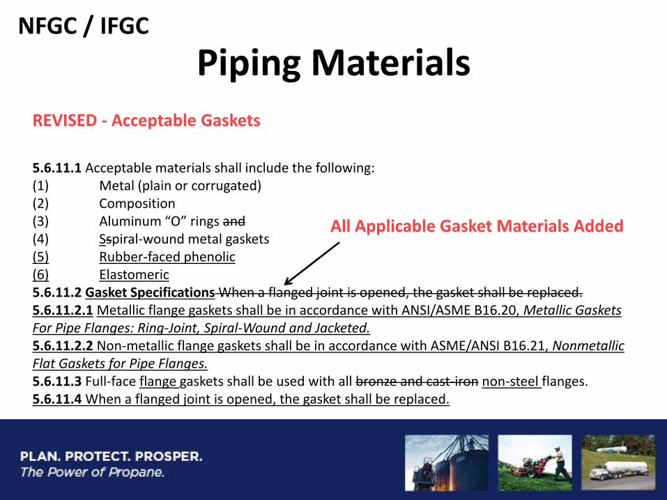
Piping Materials REVISED - Acceptable Gaskets
5.6.11.1 Acceptable materials shall include the following: (1) Metal (plain or corrugated) (2) Composition (3) Aluminum “O” rings and (4) Sspiral-wound metal gaskets (5) Rubber-faced phenolic (6) Elastomeric 5.6.11.2 Gasket Specifications When a flanged joint is opened, the gasket shall be replaced. 5.6.11.2.1 Metallic flange gaskets shall be in accordance with ANSI/ASME B16.20, Metallic Gaskets For Pipe Flanges: Ring-Joint, Spiral-Wound and Jacketed. 5.6.11.2.2 Non-metallic flange gaskets shall be in accordance with ASME/ANSI B16.21, Nonmetallic Flat Gaskets for Pipe Flanges. 5.6.11.3 Full-face flange gaskets shall be used with all bronze and cast-iron non-steel flanges. 5.6.11.4 When a flanged joint is opened, the gasket shall be replaced.
All Applicable Gasket Materials Added
NFGC / IFGC
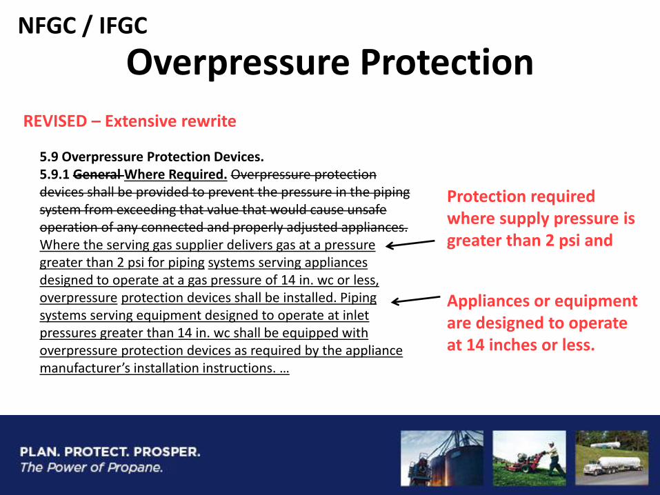
Overpressure Protection
REVISED – Extensive rewrite
5.9 Overpressure Protection Devices. 5.9.1 General Where Required. Overpressure protection devices shall be provided to prevent the pressure in the piping system from exceeding that value that would cause unsafe operation of any connected and properly adjusted appliances. Where the serving gas supplier delivers gas at a pressure greater than 2 psi for piping systems serving appliances designed to operate at a gas pressure of 14 in. wc or less, overpressure protection devices shall be installed. Piping systems serving equipment designed to operate at inlet pressures greater than 14 in. wc shall be equipped with overpressure protection devices as required by the appliance manufacturer’s installation instructions. …
Protection required where supply pressure is greater than 2 psi and
Appliances or equipment are designed to operate at 14 inches or less.
NFGC / IFGC
NFGC / IFGC
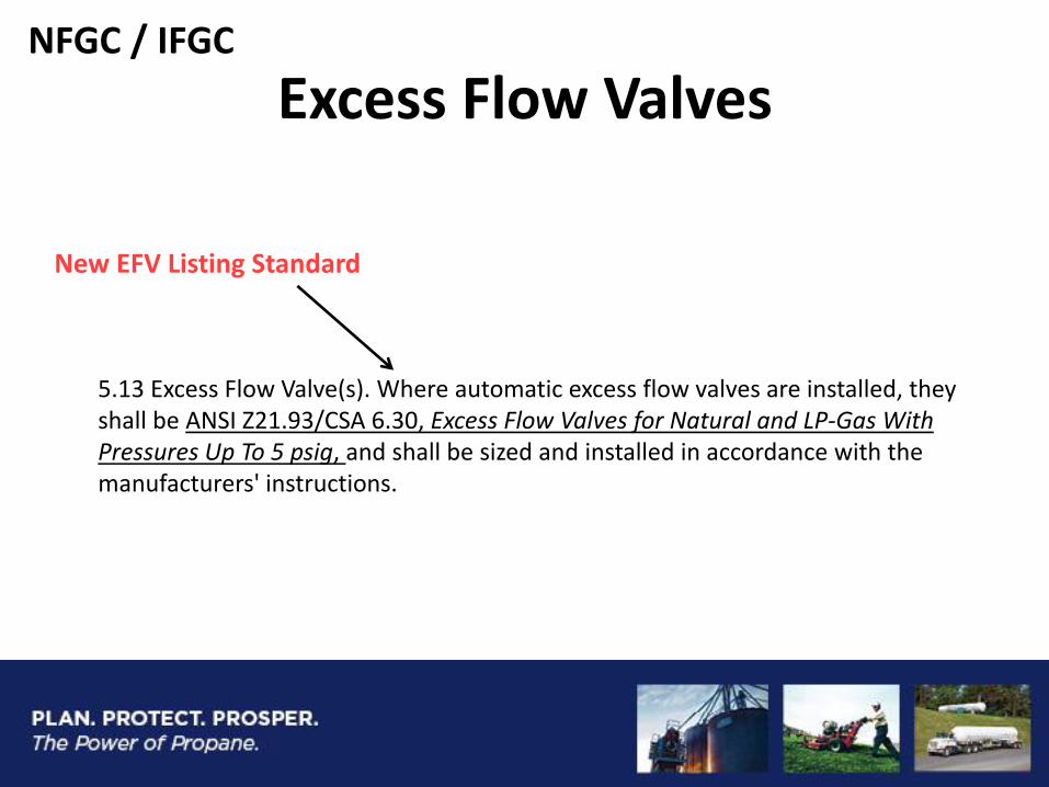
Excess Flow Valves
5.13 Excess Flow Valve(s). Where automatic excess flow valves are installed, they shall be ANSI Z21.93/CSA 6.30, Excess Flow Valves for Natural and LP-Gas With Pressures Up To 5 psig, and shall be sized and installed in accordance with the manufacturers' instructions.
New EFV Listing Standard
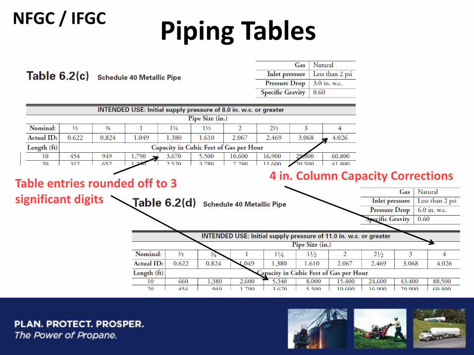
Piping Tables
Table entries rounded off to 3 significant digits
4 in. Column Capacity Corrections
NFGC / IFGC
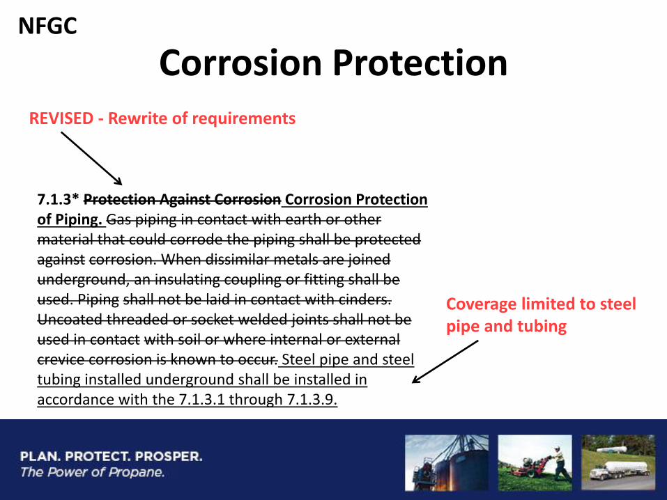
Corrosion Protection
Coverage limited to steel pipe and tubing
REVISED - Rewrite of requirements
7.1.3* Protection Against Corrosion Corrosion Protection of Piping. Gas piping in contact with earth or other material that could corrode the piping shall be protected against corrosion. When dissimilar metals are joined underground, an insulating coupling or fitting shall be used. Piping shall not be laid in contact with cinders. Uncoated threaded or socket welded joints shall not be used in contact with soil or where internal or external crevice corrosion is known to occur. Steel pipe and steel tubing installed underground shall be installed in accordance with the 7.1.3.1 through 7.1.3.9.
NFGC
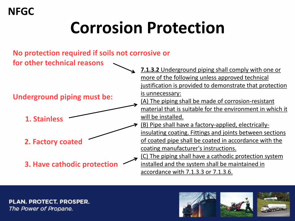
Underground piping must be:
Corrosion Protection
1. Stainless
2. Factory coated
7.1.3.2 Underground piping shall comply with one or more of the following unless approved technical justification is provided to demonstrate that protection is unnecessary: (A) The piping shall be made of corrosion-resistant material that is suitable for the environment in which it will be installed. (B) Pipe shall have a factory-applied, electrically-insulating coating. Fittings and joints between sections of coated pipe shall be coated in accordance with the coating manufacturer's instructions. (C) The piping shall have a cathodic protection system installed and the system shall be maintained in accordance with 7.1.3.3 or 7.1.3.6.
No protection required if soils not corrosive or for other technical reasons
3. Have cathodic protection
NFGC
Piping Installation
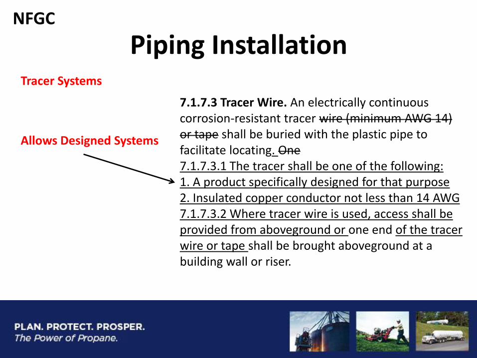
7.1.7.3 Tracer Wire. An electrically continuous corrosion-resistant tracer wire (minimum AWG 14) or tape shall be buried with the plastic pipe to facilitate locating. One 7.1.7.3.1 The tracer shall be one of the following: 1. A product specifically designed for that purpose 2. Insulated copper conductor not less than 14 AWG 7.1.7.3.2 Where tracer wire is used, access shall be provided from aboveground or one end of the tracer wire or tape shall be brought aboveground at a building wall or riser.
Tracer Systems
Allows Designed Systems
NFGC
Piping Installation
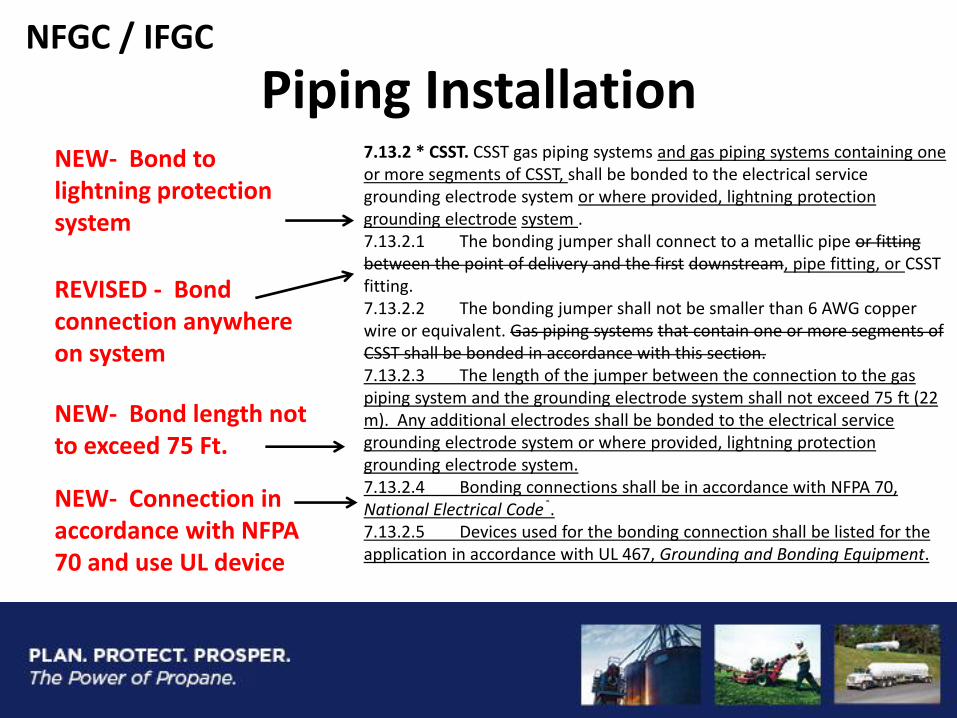
NEW- Bond length not to exceed 75 Ft.
7.13.2 * CSST. CSST gas piping systems and gas piping systems containing one or more segments of CSST, shall be bonded to the electrical service grounding electrode system or where provided, lightning protection grounding electrode system . 7.13.2.1 The bonding jumper shall connect to a metallic pipe or fitting between the point of delivery and the first downstream, pipe fitting, or CSST fitting. 7.13.2.2 The bonding jumper shall not be smaller than 6 AWG copper wire or equivalent. Gas piping systems that contain one or more segments of CSST shall be bonded in accordance with this section. 7.13.2.3 The length of the jumper between the connection to the gas piping system and the grounding electrode system shall not exceed 75 ft (22 m). Any additional electrodes shall be bonded to the electrical service grounding electrode system or where provided, lightning protection grounding electrode system. 7.13.2.4 Bonding connections shall be in accordance with NFPA 70, National Electrical Code®. 7.13.2.5 Devices used for the bonding connection shall be listed for the application in accordance with UL 467, Grounding and Bonding Equipment.
REVISED - Bond connection anywhere on system
NEW- Bond to lightning protection system
NEW- Connection in accordance with NFPA 70 and use UL device
NFGC / IFGC
Piping Installation
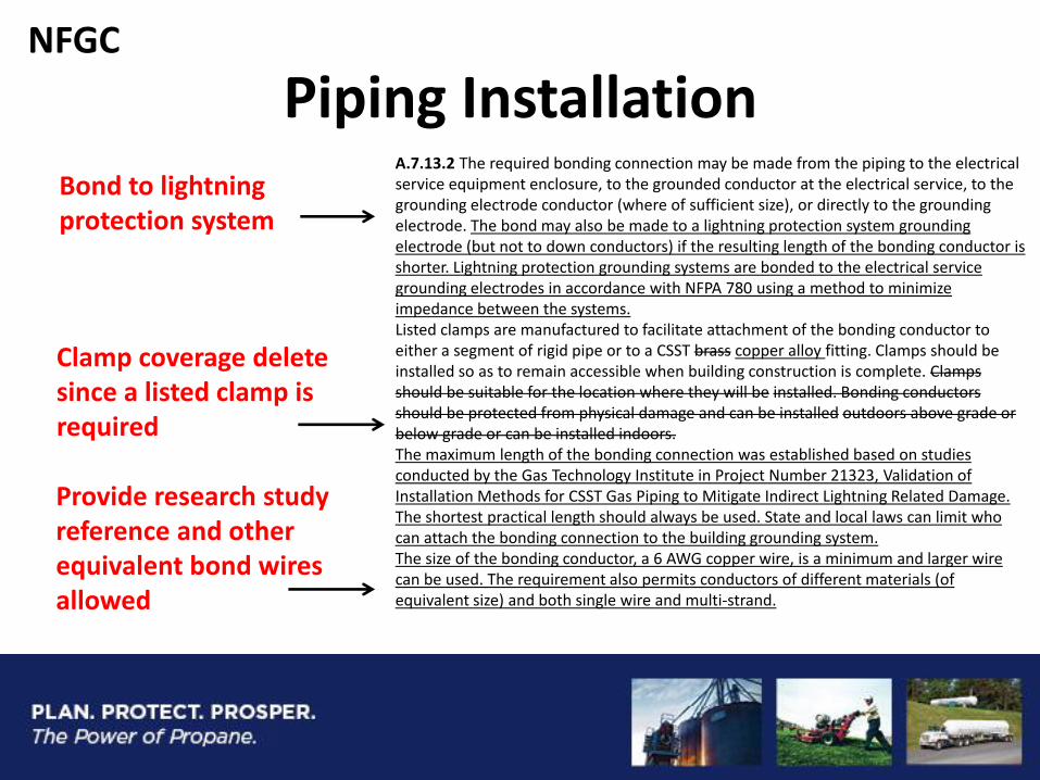
Provide research study reference and other equivalent bond wires allowed
A.7.13.2 The required bonding connection may be made from the piping to the electrical service equipment enclosure, to the grounded conductor at the electrical service, to the grounding electrode conductor (where of sufficient size), or directly to the grounding electrode. The bond may also be made to a lightning protection system grounding electrode (but not to down conductors) if the resulting length of the bonding conductor is shorter. Lightning protection grounding systems are bonded to the electrical service grounding electrodes in accordance with NFPA 780 using a method to minimize impedance between the systems. Listed clamps are manufactured to facilitate attachment of the bonding conductor to either a segment of rigid pipe or to a CSST brass copper alloy fitting. Clamps should be installed so as to remain accessible when building construction is complete. Clamps should be suitable for the location where they will be installed. Bonding conductors should be protected from physical damage and can be installed outdoors above grade or below grade or can be installed indoors. The maximum length of the bonding connection was established based on studies conducted by the Gas Technology Institute in Project Number 21323, Validation of Installation Methods for CSST Gas Piping to Mitigate Indirect Lightning Related Damage. The shortest practical length should always be used. State and local laws can limit who can attach the bonding connection to the building grounding system. The size of the bonding conductor, a 6 AWG copper wire, is a minimum and larger wire can be used. The requirement also permits conductors of different materials (of equivalent size) and both single wire and multi-strand.
Clamp coverage delete since a listed clamp is required
Bond to lightning protection system
NFGC
Piping Installation
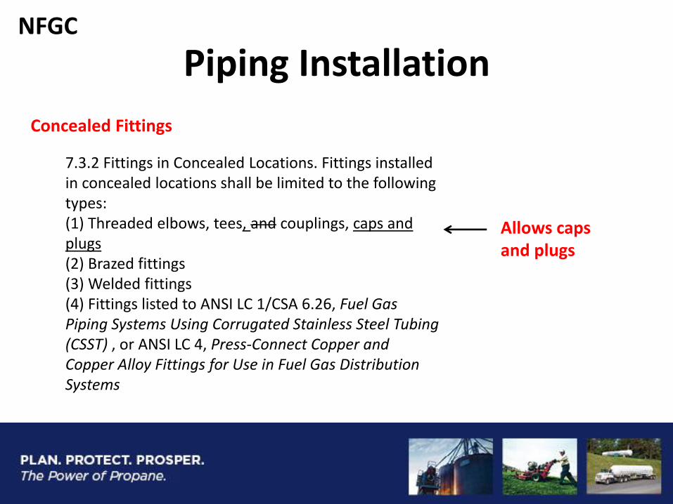
Concealed Fittings
Allows caps and plugs
7.3.2 Fittings in Concealed Locations. Fittings installed in concealed locations shall be limited to the following types: (1) Threaded elbows, tees, and couplings, caps and plugs (2) Brazed fittings (3) Welded fittings (4) Fittings listed to ANSI LC 1/CSA 6.26, Fuel Gas Piping Systems Using Corrugated Stainless Steel Tubing (CSST) , or ANSI LC 4, Press-Connect Copper and Copper Alloy Fittings for Use in Fuel Gas Distribution Systems
NFGC
Shutoff Valves
Requires Support for Valves on Tubing Systems
7.3.6 Shutoff Valves in Tubing Systems. Shutoff valves in tubing systems in concealed locations shall be rigidly and securely supported independently of the tubing.
NFGC
Repair Garages In accordance with NFPA 30A
9.1.11.2 Repair Garages. Appliances installed in repair garages shall be installed in a detached building or room, separated from repair areas by walls or partitions, floors, or floor–ceiling assemblies that are constructed so as to prohibit the transmission of vapors and that have a fire resistance rating of not less than 1 hour, and that have no openings in the wall separating the repair area within 8 ft (2.4 m) of the floor. Wall penetrations shall be firestopped. Air for combustion purposes shall be obtained from the outdoors. The heating room shall not be used for the storage of combustible materials. Exception No. 1: Overhead heaters where installed not less than 8 ft (2.4 m) above the floor shall be permitted. Exception No. 2: Heating appliances for vehicle repair areas where there is no dispensing or transferring of Class I or Class II flammable or combustible liquids or LP-Gas shall be installed in accordance with NFPA 30A, Code for Motor Fuel Dispensing Facilities and Repair Garages .
NFGC
Existing Appliances
9.1.24* Existing Appliances. Where an existing appliance is located within the conditioned space of an existing building envelope and where a building envelope component, other than roofing material, is replaced or altered, the appliance installations shall be inspected to verify compliance with the provisions of 9.3 and Chapter 12. Where the appliance installations do not comply with 9.3 and Chapter 12, it shall be altered as necessary to be in compliance with such.
Building Envelope Changes – “Weatherization”
Verify Combustion Air and Venting
NFGC –Z223 ONLY
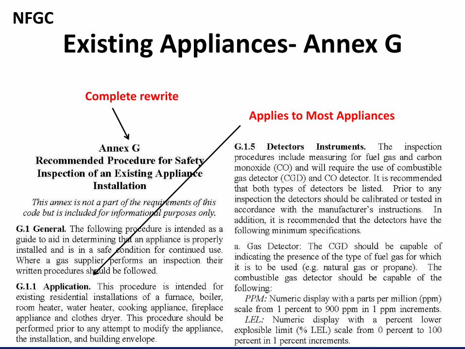
Existing Appliances- Annex G
Complete rewrite
Applies to Most Appliances
NFGC
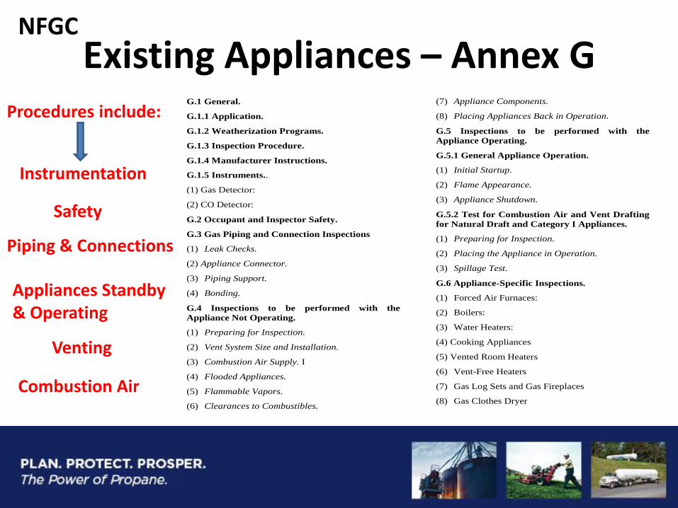
Existing Appliances – Annex G
Safety
Appliances Standby & Operating
NFGC
G.1 General.
G.1.1 Application.
G.1.2 Weatherization Programs.
G.1.3 Inspection Procedure.
G.1.4 Manufacturer Instructions.
G.1.5 Instruments..
(1) Gas Detector:
(2) CO Detector:
G.2 Occupant and Inspector Safety.
G.3 Gas Piping and Connection Inspections
(1) Leak Checks.
(2) Appliance Connector.
(3) Piping Support.
(4) Bonding.
G.4 Inspections to be performed with the
Appliance Not Operating.
(1) Preparing for Inspection.
(2) Vent System Size and Installation.
(3) Combustion Air Supply. I
(4) Flooded Appliances.
(5) Flammable Vapors.
(6) Clearances to Combustibles.
(7) Appliance Components.
(8) Placing Appliances Back in Operation.
G.5 Inspections to be performed with the
Appliance Operating.
G.5.1 General Appliance Operation.
(1) Initial Startup.
(2) Flame Appearance.
(3) Appliance Shutdown.
G.5.2 Test for Combustion Air and Vent Drafting
for Natural Draft and Category I Appliances.
(1) Preparing for Inspection.
(2) Placing the Appliance in Operation.
(3) Spillage Test.
G.6 Appliance-Specific Inspections.
(1) Forced Air Furnaces:
(2) Boilers:
(3) Water Heaters:
(4) Cooking Appliances
(5) Vented Room Heaters
(6) Vent-Free Heaters
(7) Gas Log Sets and Gas Fireplaces
(8) Gas Clothes Dryer
Instrumentation
Piping & Connections
Venting
Combustion Air
Procedures include:
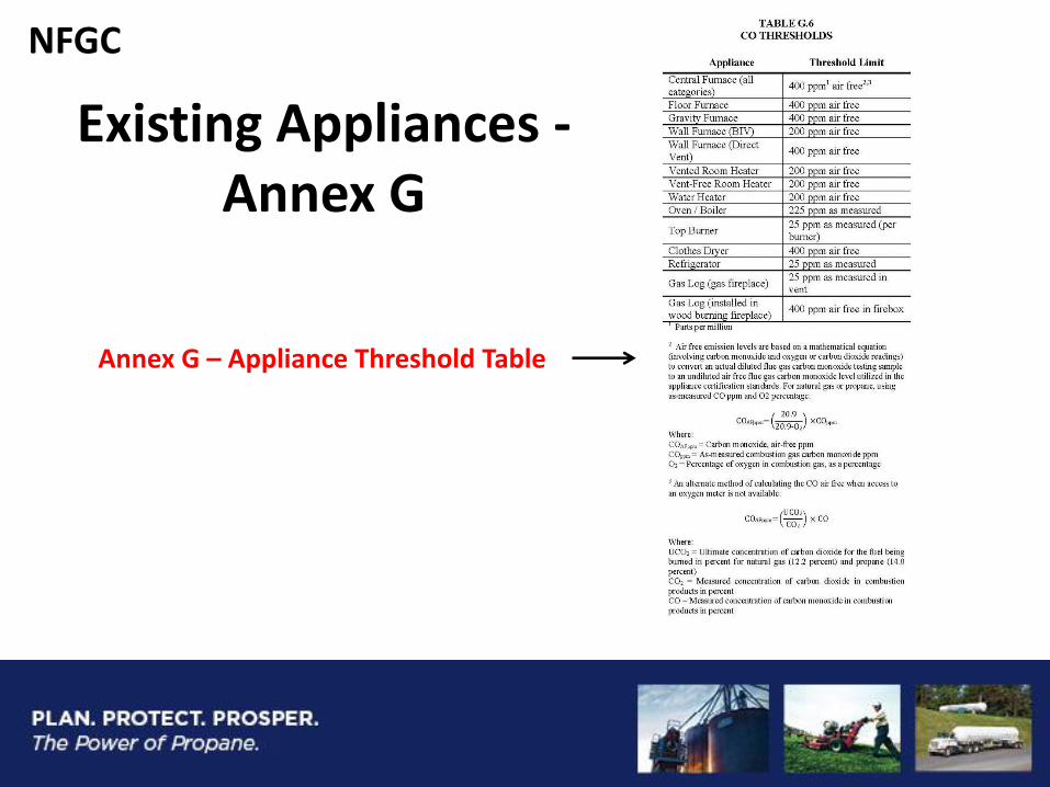
Existing Appliances - Annex G
Annex G – Appliance Threshold Table
NFGC
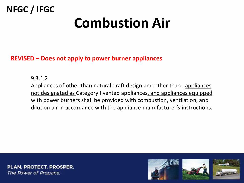
Combustion Air
REVISED – Does not apply to power burner appliances
9.3.1.2 Appliances of other than natural draft design and other than , appliances not designated as Category I vented appliances, and appliances equipped with power burners shall be provided with combustion, ventilation, and dilution air in accordance with the appliance manufacturer’s instructions.
NFGC / IFGC
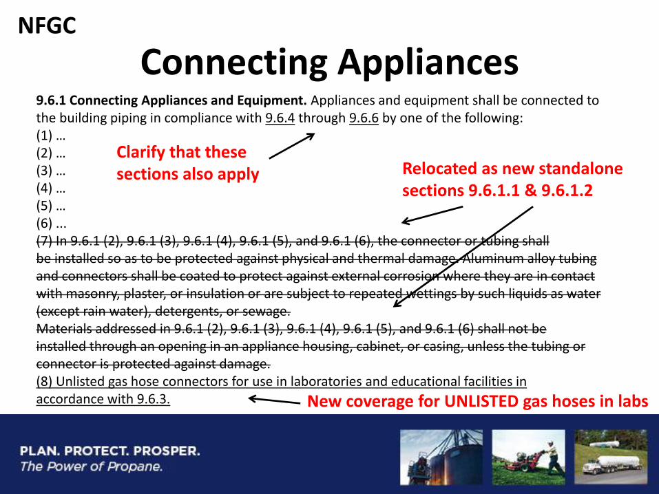
Connecting Appliances 9.6.1 Connecting Appliances and Equipment. Appliances and equipment shall be connected to the building piping in compliance with 9.6.4 through 9.6.6 by one of the following: (1) … (2) … (3) … (4) … (5) … (6) ... (7) In 9.6.1 (2), 9.6.1 (3), 9.6.1 (4), 9.6.1 (5), and 9.6.1 (6), the connector or tubing shall be installed so as to be protected against physical and thermal damage. Aluminum alloy tubing and connectors shall be coated to protect against external corrosion where they are in contact with masonry, plaster, or insulation or are subject to repeated wettings by such liquids as water (except rain water), detergents, or sewage. Materials addressed in 9.6.1 (2), 9.6.1 (3), 9.6.1 (4), 9.6.1 (5), and 9.6.1 (6) shall not be installed through an opening in an appliance housing, cabinet, or casing, unless the tubing or connector is protected against damage. (8) Unlisted gas hose connectors for use in laboratories and educational facilities in accordance with 9.6.3.
Clarify that these sections also apply Relocated as new standalone
sections 9.6.1.1 & 9.6.1.2
New coverage for UNLISTED gas hoses in labs
NFGC
Connecting Appliances
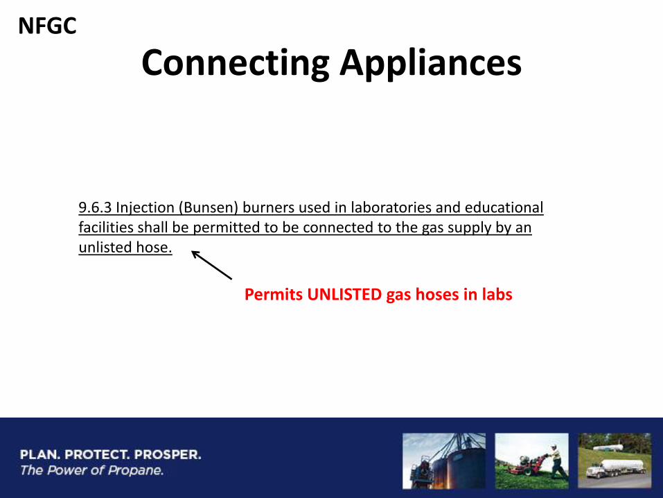
Permits UNLISTED gas hoses in labs
9.6.3 Injection (Bunsen) burners used in laboratories and educational facilities shall be permitted to be connected to the gas supply by an unlisted hose.
NFGC
Clearances around Cooking Tops
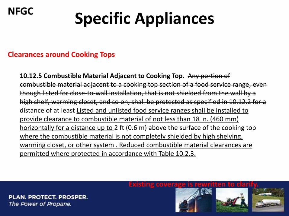
10.12.5 Combustible Material Adjacent to Cooking Top. Any portion of combustible material adjacent to a cooking top section of a food service range, even though listed for close-to-wall installation, that is not shielded from the wall by a high shelf, warming closet, and so on, shall be protected as specified in 10.12.2 for a distance of at least Listed and unlisted food service ranges shall be installed to provide clearance to combustible material of not less than 18 in. (460 mm) horizontally for a distance up to 2 ft (0.6 m) above the surface of the cooking top where the combustible material is not completely shielded by high shelving, warming closet, or other system . Reduced combustible material clearances are permitted where protected in accordance with Table 10.2.3.
Existing coverage is rewritten to clarify.
NFGC Specific Appliances
Specific Appliances Hot Plates & Laundry Stoves
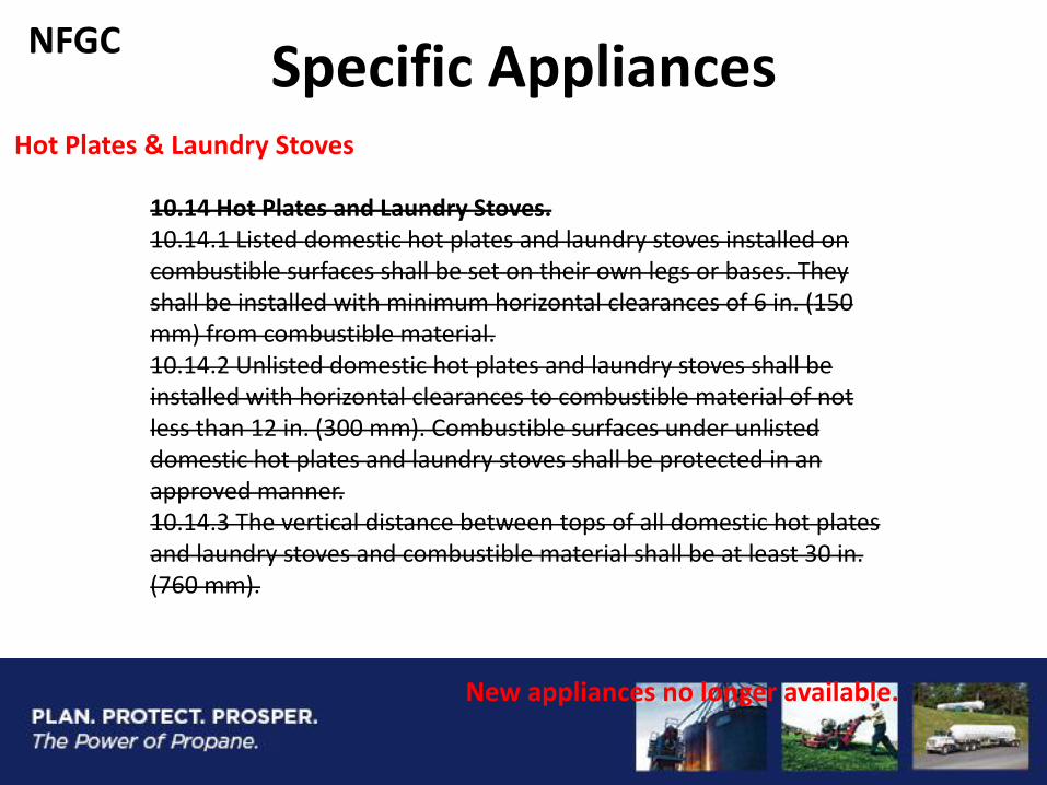
10.14 Hot Plates and Laundry Stoves. 10.14.1 Listed domestic hot plates and laundry stoves installed on combustible surfaces shall be set on their own legs or bases. They shall be installed with minimum horizontal clearances of 6 in. (150 mm) from combustible material. 10.14.2 Unlisted domestic hot plates and laundry stoves shall be installed with horizontal clearances to combustible material of not less than 12 in. (300 mm). Combustible surfaces under unlisted domestic hot plates and laundry stoves shall be protected in an approved manner. 10.14.3 The vertical distance between tops of all domestic hot plates and laundry stoves and combustible material shall be at least 30 in. (760 mm).
New appliances no longer available.
NFGC
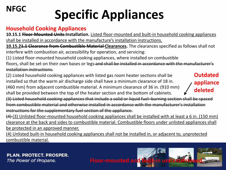
Specific Appliances Household Cooking Appliances 10.15.1 Floor-Mounted Units Installation. Listed floor-mounted and built-in household cooking appliances shall be installed in accordance with the manufacture’s installation instructions. 10.15.21.1 Clearance from Combustible Material Clearances. The clearances specified as follows shall not interfere with combustion air, accessibility for operation, and servicing: (1) Listed floor-mounted household cooking appliances, where installed on combustible floors, shall be set on their own bases or legs and shall be installed in accordance with the manufacturer's installation instructions. (2) Listed household cooking appliances with listed gas room heater sections shall be installed so that the warm air discharge side shall have a minimum clearance of 18 in. (460 mm) from adjacent combustible material. A minimum clearance of 36 in. (910 mm) shall be provided between the top of the heater section and the bottom of cabinets. (3) Listed household cooking appliances that include a solid or liquid fuel–burning section shall be spaced from combustible material and otherwise installed in accordance with the manufacturer's installation instructions for the supplementary fuel section of the appliance. (4) (3) Unlisted floor-mounted household cooking appliances shall be installed with at least a 6 in. (150 mm) clearance at the back and sides to combustible material. Combustible floors under unlisted appliances shall be protected in an approved manner. (4) Unlisted built-in household cooking appliances shall not be installed in, or adjacent to, unprotected combustible material.
Floor-mounted and built-in units combined.
Outdated appliance deleted
NFGC
Specific Appliances Household Cooking Appliances
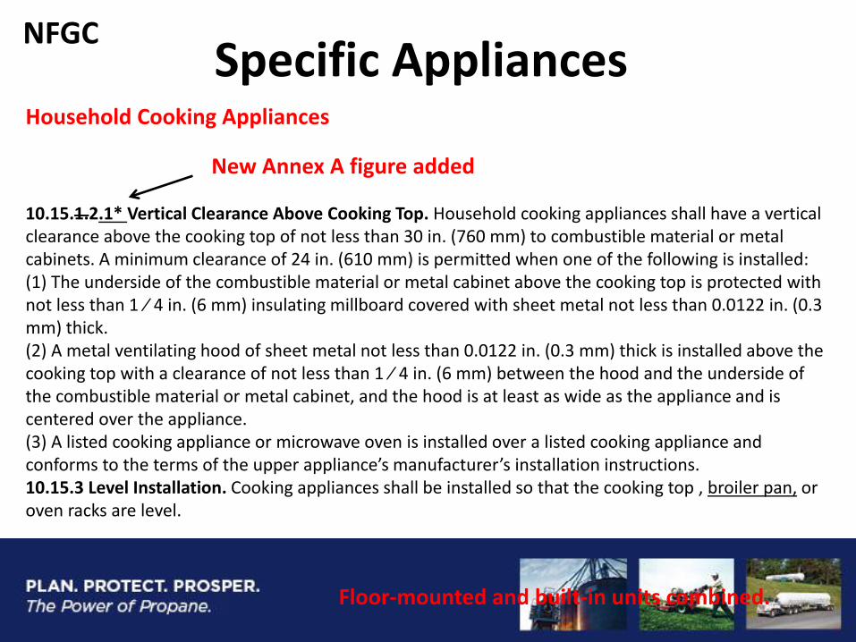
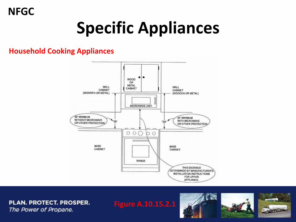
10.15.1.2.1* Vertical Clearance Above Cooking Top. Household cooking appliances shall have a vertical clearance above the cooking top of not less than 30 in. (760 mm) to combustible material or metal cabinets. A minimum clearance of 24 in. (610 mm) is permitted when one of the following is installed: (1) The underside of the combustible material or metal cabinet above the cooking top is protected with not less than 1 ⁄ 4 in. (6 mm) insulating millboard covered with sheet metal not less than 0.0122 in. (0.3 mm) thick. (2) A metal ventilating hood of sheet metal not less than 0.0122 in. (0.3 mm) thick is installed above the cooking top with a clearance of not less than 1 ⁄ 4 in. (6 mm) between the hood and the underside of the combustible material or metal cabinet, and the hood is at least as wide as the appliance and is centered over the appliance. (3) A listed cooking appliance or microwave oven is installed over a listed cooking appliance and conforms to the terms of the upper appliance’s manufacturer’s installation instructions. 10.15.3 Level Installation. Cooking appliances shall be installed so that the cooking top , broiler pan, or oven racks are level.
Floor-mounted and built-in units combined.
New Annex A figure added
NFGC
Specific Appliances Household Cooking Appliances
Figure A.10.15.2.1
NFGC
Venting
Plastic pipe used in venting systems
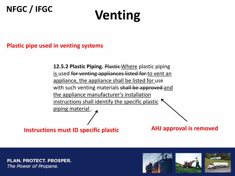
12.5.2 Plastic Piping. Plastic Where plastic piping is used for venting appliances listed for to vent an appliance, the appliance shall be listed for use with such venting materials shall be approved and the appliance manufacturer's installation instructions shall identify the specific plastic piping material .
AHJ approval is removed Instructions must ID specific plastic
NFGC / IFGC
Venting
Sizing of Category II, III & IV Vents
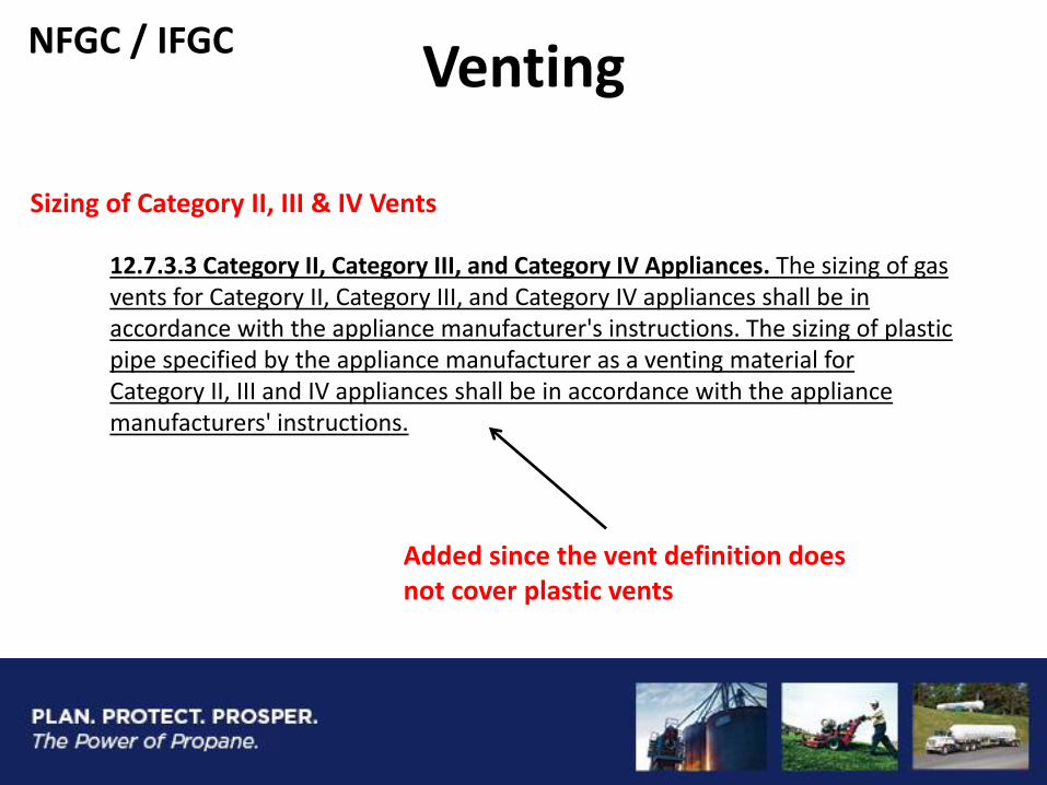
Added since the vent definition does not cover plastic vents
12.7.3.3 Category II, Category III, and Category IV Appliances. The sizing of gas vents for Category II, Category III, and Category IV appliances shall be in accordance with the appliance manufacturer's instructions. The sizing of plastic pipe specified by the appliance manufacturer as a venting material for Category II, III and IV appliances shall be in accordance with the appliance manufacturers' instructions.
NFGC / IFGC
2018 Edition Revision
Status
• Open for Public Input
• Due Date: July 6th 2018
• Use NFPA Online Proposal System