nfc forum type 3 tag operation ... -...
TRANSCRIPT

Type 3 Tag Operation Specification Technical Specification
NFC ForumTM T3TOP 1.1
NFCForum-TS-Type-3-Tag_1.1 2011-06-28

RESTRICTIONS ON USE This specification is copyright © 2005-2011 by the NFC Forum, and was made available pursuant to a license agreement entered into between the recipient (Licensee) and NFC Forum, Inc. (Licensor) and may be used only by Licensee, and in compliance with the terms of that license agreement (License). If you are not the Licensee, you may read this Specification, but are not authorized to implement or make any other use of this specification. However, you may obtain a copy of this Specification and implementation rights at the following page of Licensor's website: http://www.nfc-forum.org/specs/spec_license after entering into and agreeing to such license terms as Licensor is then requiring. On the date that this specification was downloaded by Licensee, the non-implementation terms of that license were as follows:
1. LICENSE GRANT.
Licensor hereby grants Licensee the right, without charge, to copy (for internal purposes only) and share this Specification with Licensee's members, employees and (to the extent related to Licensees use of this Specification) consultants. This license grant does not include the right to sublicense, modify or create derivative works based upon the Specification.
2. NO WARRANTIES.
THE SPECIFICATION IS PROVIDED "AS IS", WITHOUT WARRANTY OF ANY KIND, EXPRESS OR IMPLIED, INCLUDING BUT NOT LIMITED TO WARRANTIES OF MERCHANTABILITY, FITNESS FOR A PARTICULAR PURPOSE, ACCURACY, COMPLETENESS AND NONINFRINGEMENT OF THIRD PARTY RIGHTS. IN NO EVENT SHALL LICENSOR, ITS MEMBERS OR ITS CONTRIBUTORS BE LIABLE FOR ANY CLAIM, OR ANY DIRECT, SPECIAL, INDIRECT OR CONSEQUENTIAL DAMAGES, OR ANY DAMAGES WHATSOEVER RESULTING FROM LOSS OF USE, DATA OR PROFITS, WHETHER IN AN ACTION OF CONTRACT, NEGLIGENCE OR OTHER TORTIOUS ACTION, ARISING OUT OF OR IN CONNECTION WITH THE USE OR PERFORMANCE OF THE SPECIFICATION.
3. THIRD PARTY RIGHTS.
Without limiting the generality of Section 2 above, LICENSOR ASSUMES NO RESPONSIBILITY TO COMPILE, CONFIRM, UPDATE OR MAKE PUBLIC ANY THIRD PARTY ASSERTIONS OF PATENT OR OTHER INTELLECTUAL PROPERTY RIGHTS THAT MIGHT NOW OR IN THE FUTURE BE INFRINGED BY AN IMPLEMENTATION OF THE SPECIFICATION IN ITS CURRENT, OR IN ANY FUTURE FORM. IF ANY SUCH RIGHTS ARE DESCRIBED ON THE SPECIFICATION, LICENSOR TAKES NO POSITION AS TO THE VALIDITY OR INVALIDITY OF SUCH ASSERTIONS, OR THAT ALL SUCH ASSERTIONS THAT HAVE OR MAY BE MADE ARE SO LISTED.
4. TERMINATION OF LICENSE.
In the event of a breach of this Agreement by Licensee or any of its employees or members, Licensor shall give Licensee written notice and an opportunity to cure. If the breach is not cured within thirty (30) days after written notice, or if the breach is of a nature that cannot be cured, then Licensor may immediately or thereafter terminate the licenses granted in this Agreement.
5. MISCELLANEOUS.
All notices required under this Agreement shall be in writing, and shall be deemed effective five days from deposit in the mails. Notices and correspondence to the NFC Forum address as it appears below. This Agreement shall be construed and interpreted under the internal laws of the United States and the Commonwealth of Massachusetts, without giving effect to its principles of conflict of law.
NFC Forum, Inc. 401 Edgewater Place, Suite 600 Wakefield, MA, USA 01880

Contents
Type 3 Tag Operation Specification Page i
Contents 1 Introduction .................................................................................................... 1
1.1 Objectives ...................................................................................................................... 1 1.2 Applicable Documents or References ........................................................................... 1 1.3 Administration ............................................................................................................... 1 1.4 Name and Logo Usage .................................................................................................. 2 1.5 Intellectual Property ...................................................................................................... 2 1.6 Special Word Usage ...................................................................................................... 2 1.7 Convention and Notations ............................................................................................. 2
1.7.1 Representation of Numbers ............................................................................ 2 1.8 Abbreviations ................................................................................................................ 3 1.9 Glossary ......................................................................................................................... 3
2 Memory Structure and Management ............................................................ 6 2.1 Blocks ............................................................................................................................ 6 2.2 Services ......................................................................................................................... 6 2.3 System Information ....................................................................................................... 6
2.3.1 Manufacture Information ................................................................................ 6 2.3.2 System Definition Information ....................................................................... 7 2.3.3 Service Definition Information ....................................................................... 7
3 Analog Interface ............................................................................................ 8
4 Framing and Transmission Handling .......................................................... 9 4.1 Frame Structure ............................................................................................................. 9 4.2 Communication Protocol ............................................................................................... 9 4.3 Communication Endpoints ............................................................................................ 9
5 Command Set .............................................................................................. 10 5.1 State Diagram (Informative) ........................................................................................ 10 5.2 Command and Response Format ................................................................................. 10 5.3 Polling Command ........................................................................................................ 11 5.4 Check Command ......................................................................................................... 11
5.4.1 Command ...................................................................................................... 11 5.4.2 Response ....................................................................................................... 12
5.5 Update Command ........................................................................................................ 13 5.5.1 Command ...................................................................................................... 13 5.5.2 Response ....................................................................................................... 14
5.6 Block List .................................................................................................................... 15 5.6.1 Block List Format ......................................................................................... 15
5.7 Status Flag ................................................................................................................... 16 5.7.1 Status Flag1 .................................................................................................. 16 5.7.2 Status Flag2 .................................................................................................. 16
6 NDEF Detection and Access ....................................................................... 18 6.1 NDEF Management Data ............................................................................................ 18
6.1.1 System Code ................................................................................................. 18 6.1.2 Attribute Information Block ......................................................................... 18 6.1.3 Versioning ..................................................................................................... 20
6.2 NDEF Storage ............................................................................................................. 21 6.3 Life Cycle .................................................................................................................... 22 6.4 Command Sequence Description................................................................................. 23

Tables
Type 3 Tag Operation Specification Page ii
6.4.1 NDEF Detection ........................................................................................... 23 6.4.2 Read NDEF Message .................................................................................... 24 6.4.3 Write NDEF Message ................................................................................... 25 6.4.4 State Changes ................................................................................................ 27
A. Typical Activation Sequence ...................................................................... 28
B. Revision History .......................................................................................... 29
Tables Table 1: Abbreviations .................................................................................................................... 3
Table 2: Access Attributes............................................................................................................... 7
Table 3: Generic Data Format for T3T Commands ...................................................................... 10
Table 4: Generic Data Format for T3T Responses ........................................................................ 11
Table 5: Check Command Parameters .......................................................................................... 11
Table 6: Check Response Parameters ............................................................................................ 12
Table 7: Update Command Parameters ......................................................................................... 14
Table 8: Update Response Parameters .......................................................................................... 15
Table 9: Error Code List ................................................................................................................ 17
Table 10: Handling of the Mapping Document Version Numbers................................................ 21
Table 11: NDEF Services .............................................................................................................. 21
Table 12: Revision History ............................................................................................................ 29
Figures Figure 1: Manufacture Information ................................................................................................. 6
Figure 2: Type 3 Tag State Diagram ............................................................................................. 10
Figure 3: Example of Check Command / Response ...................................................................... 13
Figure 4: Two Bytes Block List Element ...................................................................................... 15
Figure 5: Three Bytes Block List Element .................................................................................... 16
Figure 6: Mapping of NDEF to a Type 3 Tag ............................................................................... 18
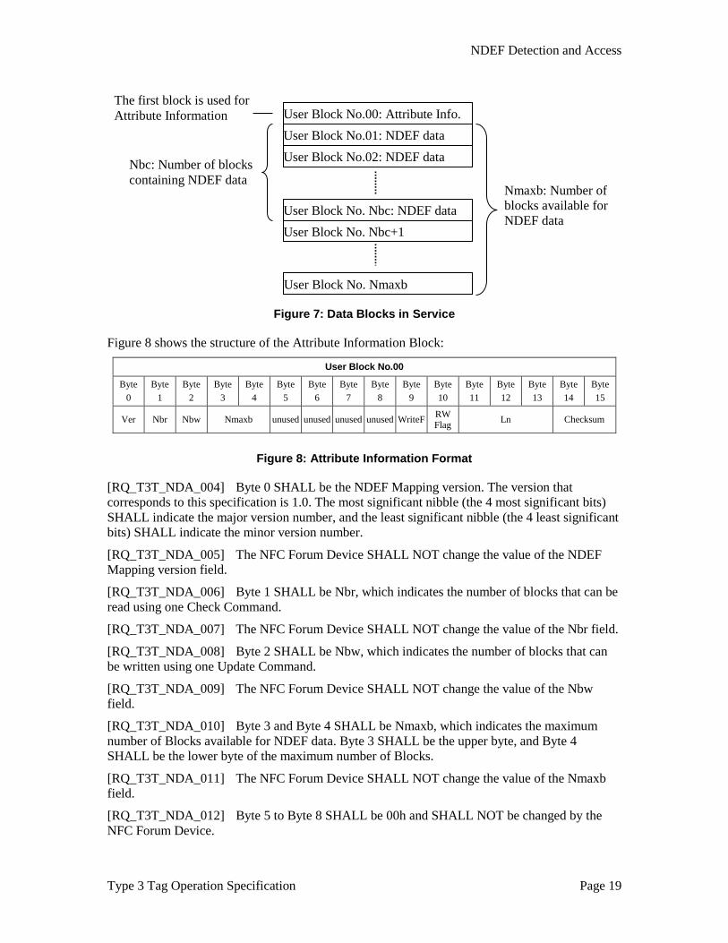
Figure 7: Data Blocks in Service ................................................................................................... 19
Figure 8: Attribute Information Format ........................................................................................ 19
Figure 9: Relation between NDEF Data and Storage Blocks ........................................................ 22
Figure 10: Life Cycle States .......................................................................................................... 23
Figure 11: General Sequence for Detecting NDEF Data .............................................................. 24
Figure 12: General Sequence for Reading NDEF Data ................................................................. 25
Figure 13: General Sequence for Writing NDEF Data .................................................................. 27
Introduction
Type 3 Tag Operation Specification Page 1
1 Introduction This specification is part of the NFC Forum documentation about tag types that NFC Forum Devices need to support in NFC Forum Reader/Writer Mode.
This specification documents how an NFC Forum Device SHALL operate an NFC Forum Type 3 Tag. This is not a specification of the NFC Forum Type 3 Tag itself.
1.1 Objectives The purpose of this specification is to document the requirements and to specify, with a set of rules and guidelines, the NFC Forum Device operation and management of a Type 3 Tag.
This specification also defines data mapping and how the NFC Forum Device detects, reads, and writes NDEF data into the Type 3 Tag Platform in order to achieve and maintain interchangeability and interoperability.
1.2 Applicable Documents or References [ANALOG] NFC Analog,
In progress, NFC Forum
[DIGITAL] NFC Digital Protocol, Version 1.0, NFC Forum
[NDEF] NFC Data Exchange Format, Version 1.0, NFC Forum
[RFC2119] Key words for use in RFCs to Indicate Requirement Levels, RFC 2119, S. Bradner, March 1997, Internet Engineering Task Force
1.3 Administration The NFC Forum Type 3 Tag Operation Specification is an open specification supported by the Near Field Communication Forum, Inc., located at:
401 Edgewater Place, Suite 600 Wakefield, MA, 01880
Tel.: +1 781-876-8955 Fax: +1 781-610-9864
http://www.nfc-forum.org/
The NFC Devices Technical Working Group maintains this specification. Comments, errors, and other feedback can be submitted at http://www.nfc-forum.org/apps/group_public/document.php?document_id=9800&wg_abbrev=chairs.

Introduction
Type 3 Tag Operation Specification Page 2
1.4 Name and Logo Usage The Near Field Communication Forum’s policy regarding the use of the trademarks NFC Forum and the NFC Forum logo is as follows:
• Any company MAY claim compatibility with NFC Forum specifications, whether a member of the NFC Forum or not.
• Permission to use the NFC Forum logos is automatically granted to designated members only as stipulated on the most recent Membership Privileges document, during the period of time for which their membership dues are paid.
• Member’s distributors and sales representatives MAY use the NFC Forum logo in promoting member’s products sold under the name of the member.
• The logo SHALL be printed in black or in color as illustrated on the Logo Page that is available from the NFC Forum at the address above. The aspect ratio of the logo SHALL be maintained, but the size MAY be varied. Nothing MAY be added to or deleted from the logos.
• Since the NFC Forum name is a trademark of the Near Field Communication Forum, the following statement SHALL be included in all published literature and advertising material in which the name or logo appears:
NFC Forum and the NFC Forum logo are trademarks of the Near Field Communication Forum.
1.5 Intellectual Property The Type 3 Tag Operation Specification conforms to the Intellectual Property guidelines specified in the NFC Forum's Intellectual Property Rights Policy, as outlined in the NFC Forum Rules of Procedure. These documents are available on the NFC Forum website.
1.6 Special Word Usage The key words “MUST”, “MUST NOT”, “REQUIRED”, “SHALL”, “SHALL NOT”, “SHOULD”, “SHOULD NOT”, “RECOMMENDED”, “MAY”, and “OPTIONAL” in this document are to be interpreted as described in [RFC2119].
1.7 Convention and Notations
1.7.1 Representation of Numbers The following conventions and notations apply in this document unless otherwise stated.
• Binary numbers are represented by strings of digits 0 and 1 shown with the most significant bit (msb) left and the least significant bit (lsb) right, “b” is added at the end.
Example: 11110101b
• Hexadecimal numbers are represented using the numbers 0 - 9 and the characters A – F, an “h” is added at the end. The most significant byte (MSB) is shown on the left, the least significant byte (LSB) on the right.
Example: F5h

Introduction
Type 3 Tag Operation Specification Page 3
• Decimal numbers are represented as is (without any tailing character).
Example: 245
1.8 Abbreviations The abbreviations as used in this document are defined in Table 1.
Table 1: Abbreviations
Abbreviation Description
lsb least significant bit
LSB Least Significant Byte
msb most significant bit
MSB Most Significant Byte
NDEF NFC Data Exchange Format
1.9 Glossary Access Attribute
The lowest 6 bits of Service Code. This value determines how to access Block Data.
Access Mode
A value specified in the Block List Element that identifies the method of access to use when accessing Block Data.
Block
The smallest data unit written to or read from memory.
Block Data
• Data to be written to or read from a Block.
• Data to be stored to a Block.
Block List
The enumeration (i.e., the ordered array) of all Block List Element instances.
Block List Element
Indicates the block number, the position of the Service within the Service Code List, and the access mode for one block.
Block Number
Indicates the logical position of a data block belonging to a specific Service. The NFC Forum Device uses this number to access the memory data.
Command
An instruction from one device to another device in order to move the other device through a state machine.

Introduction
Type 3 Tag Operation Specification Page 4
IDm
Manufacture ID. The Reader/Writer uses this 8 byte number to identify each Type 3 Tag with which to communicate.
Ln
Length of the NDEF data in bytes.
Nbc
Number of Blocks used by the NDEF data stored on the Type 3 Tag.
Nbr
Number of Blocks that can be read by the Check Command at one time.
Nbw
Number of Blocks that can be written by the Update Command at one time.
NFC Forum Device
NFC-Forum-compliant device. For this document, the NFC Forum Device is always acting in Reader/Writer mode, which is similar to a Proximity Coupling Device (PCD) in ISO terminology.
Nmaxb
Maximum number of Blocks available for NDEF data on a Type 3 Tag.
Overlap Service
A Service that shares the same Block Data with another service.
PMm
Manufacturer Parameter that is pre-configured by the Type 3 Tag manufacturer.
Reader/Writer
Role of an NFC Forum Device reached when an NFC Forum Device in Poll Mode has gone through a number of Activities. In this mode, the NFC Forum Device behaves like a legacy contactless reader and uses Commands from one of the Technology Subsets.
Response
Information sent from one device to another device upon receipt of a Command. The information received by the other device should allow this other device to continue the data exchange.
RWflag
Shows whether the Type 3 Tag is “read only” or allows “read/write” access.
Service
The concept that identifies both the method of access to the Block Data and a set of Block Data. A Type 3 Tag can contain more than one Service.
Service Code
The value that uniquely identifies each Service.

Introduction
Type 3 Tag Operation Specification Page 5
Service Code List
List of Service Codes that indicate which Services can be accessed.
Service Code List Order
The Service Code List Order is a field in each Block List Element. It identifies the Service Code that the Block belongs to. The value is the index of this Service Code in the Service Code List.
Status Flag
The information that indicates the error status of a Type 3 Tag, consisting of Status Flag1 and Status Flag2.
Technology
A group of transmission Parameters defined by the NFC standard that makes a complete communication protocol. A non-exhaustive list of transmission Parameters is: RF carrier, communication mode, bit rate, modulation scheme, bit-level coding, frame format, protocol, and Command set. NFC defines three groups and therefore three Technologies: NFC-A, NFC-B, and NFC-F. The three Technologies use the same RF carrier (13.56 MHz). Each Technology uses its own modulation scheme, bit-level coding, and frame format, but may have the same protocol and Command set.
Technology Subset
A legacy platform supporting a subset of a Technology. A Technology Subset supports at least the Poll Command of the Technology. The four Technology Subsets described in this specification are:
• Type 1 Tag Platform, which uses a particular subset of NFC-A, excluding anti-collision.
• Type 2 Tag Platform, which uses a particular subset of NFC-A, including anti-collision.
• Type 3 Tag Platform, which uses a particular subset of NFC-F.
• Type 4 Tag Platform, which uses a particular subset of NFC-A or NFC-B, including anti-collision.
Type 3 Tag
NFC Forum Type 3 compatible Tag, card, or token, including a contactless IC chip, which has built-in memory and memory access functions. The physical shape is not defined.
WriteFlag
Flag that indicates the current process of writing (ongoing or not).

Memory Structure and Management
Type 3 Tag Operation Specification Page 6
2 Memory Structure and Management
2.1 Blocks The basic unit of information used in memory management is called a block. Each block has a fixed size of 16 bytes. The number of memory blocks available depends on the chip hardware. Memory blocks are not addressed directly but relative to the Service they belong to.
2.2 Services Services are similar to files in a file system. Each Service has a number of memory blocks associated with it. Services can be addressed using their Service Code, which must be unique inside each Type 3 Tag.
2.3 System Information Each Type 3 Tag contains management data, called “System Information”. The System Information of a Type 3 Tag consists of the following parts:
• Manufacture Information
• System Definition Information
• Service Definition Information
Manufacture ID Information and System Definition Information are pre-assigned by the Type 3 Tag manufacturer.
2.3.1 Manufacture Information Manufacture Information consists of the Manufacture ID (IDm) and the Manufacture Parameter (PMm). The Manufacture Information cannot be deleted or rewritten by users.
Figure 1: Manufacture Information
2.3.1.1 Manufacture ID (IDm) The Manufacture ID (IDm) is an 8 byte number that is used by the NFC Forum Device to address a Type 3 Tag.
The IDm is defined in [DIGITAL] under the name of NFCID2.
Df D0 D1 D2 D3 D4 D5 D6 D7 D8 D9 Da Db Dc Dd De Df
IDm PMm Manufacture Information (16 bytes)
Maximum Response
Time Parameter
Update
Check

Memory Structure and Management
Type 3 Tag Operation Specification Page 7
2.3.1.2 Manufacture Parameter (PMm) The Manufacture Parameter (PMm) contains the Maximum Response Time parameters.
The PMm consists of the following fields defined in [DIGITAL] as part of SENSF_RES: PAD0, PAD1, MRTICHECK, MRTIUPDATE, and PAD2.
2.3.2 System Definition Information The System Definition Information consists of the System Code.
The System Code is a 2 byte number. The NFC Forum Device can use the corresponding parameter in the Polling Command to poll targets that have a specific System Code.
The System Code is coded in Big Endian order.
2.3.3 Service Definition Information A Service Definition Information is present for each Service that exists on a Type 3 Tag. It consists of the Service Code and the Number of Blocks for the Service.
The Service Code uniquely identifies the Service on a Type 3 Tag. It has a length of 2 bytes. The format is Little Endian.
The Service Code consists of a Service Number and an Access Attribute. The Service Number has a length of 10 bits (the 10 most significant bits of the 2 bytes) and is unique for each Service of a Type 3 Tag. The Access Attribute has a length of 6 bits (the 6 least significant bits of the Service Code) and specifies the permissions for accessing the associated memory blocks.
[RQ_T3T_MEM_001] The Access Attribute SHALL be interpreted by the NFC Forum Device as described in Table 2:
Table 2: Access Attributes
Value Access Attribute Comment
001001b Read/Write Data can be read or written.
001011b Read only Only reading data is possible.
The Number of Blocks is a 2 byte number specifying the number of memory blocks associated with this Service.
Each Service Definition Information usually references a number of memory blocks that are exclusively used by this Service. The only exceptions are Overlap Services, which share the same memory blocks but have different Access Attributes (e.g., read only or read/write).

Analog Interface
Type 3 Tag Operation Specification Page 8
3 Analog Interface The RF interface of the NFC Forum Device is defined in [ANALOG].
[RQ_T3T_RFI_001] The NFC Forum Device SHALL comply with the analog interface as defined in [ANALOG] for NFC-F.

Framing and Transmission Handling
Type 3 Tag Operation Specification Page 9
4 Framing and Transmission Handling
4.1 Frame Structure [RQ_T3T_FTH_001] The NFC Forum Device SHALL comply with the Sequence Format, the Bit Level Coding, Frame Format, and Data and Payload Format defined in [DIGITAL] for Type 3 Tag Platform.
4.2 Communication Protocol [RQ_T3T_FTH_002] The communication protocol SHALL comply with the requirements given in [DIGITAL] Section 7 for half-duplex communication protocols and the definitions given in [DIGITAL] for the Type 3 Tag Platform.
4.3 Communication Endpoints The NFC Forum Device and the Type 3 Tag are always the endpoints of the communication protocol described in Section 4.1 as this protocol is a link layer protocol.
However, the exchange of Commands and Responses is a higher communication layer and happens between two entities capable of constructing and extracting the Commands and Responses.
The entity extracting the Commands and constructing the Responses is always part of the Type 3 Tag. The entity constructing the Commands and extracting the Responses may be part of the NFC Forum Device, but might also be part of a device connected via another network to the NFC Forum Device. In this case, the NFC Forum Device forwards Command Packet Data it received from an entity via another network to the Type 3 Tag by encapsulating the Packet Data using the frame format described in [DIGITAL].
In a similar way, Response Packet Data received from the Type 3 Tag must be sent to the receiving entity by using the protocols of the other network. In this case, the NFC Forum Device does not need to interpret the data sent to and received from the Type 3 Tag.
NOTE Application developers can offer a low-level interface to send and receive arbitrary data to a Type 3 Tag. Such a low-level interface enables a number of applications that require a remote entity to communicate with a Type 3 Tag.

Command Set
Type 3 Tag Operation Specification Page 10
5 Command Set This section describes the Command set of a Type 3 Tag, which consists of the Polling, Check, and Update Commands. Additionally, an informative state diagram of the Type 3 Tag is provided.
5.1 State Diagram (Informative) This section shows the state diagram of a Type 3 Tag. This section is informative only.
A Type 3 Tag has only one state called “Mode 0”. In this state, the Polling Command, Check Command, and Update Command can be received. None of these Commands change the state of the Type 3 Tag.
Figure 2: Type 3 Tag State Diagram
5.2 Command and Response Format [RQ_T3T_CRF_001] An NFC Forum Device SHALL format Type 3 Tag Commands as specified in Table 3:
Table 3: Generic Data Format for T3T Commands
Byte 1 Byte 2..X
Command Code Command Parameters
[RQ_T3T_CRF_002] An NFC Forum Device SHALL interpret Type 3 Tag Responses as specified in Table 4:
Polling Check Update
Power Off
Mode 0
Power Off
Power On

Command Set
Type 3 Tag Operation Specification Page 11
Table 4: Generic Data Format for T3T Responses
Byte 1 Byte 2..X
Response Code Response Parameters
5.3 Polling Command The communication between the NFC Forum Device and a Type 3 Tag begins with the Polling Command issued by the NFC Forum Device. The Polling Command is used to detect the Type 3 Tags in the field. It is also used for initialization and anti-collision.
[RQ_T3T_CSE_001] The Polling Command is fully specified in [DIGITAL] under the name of SENSF_REQ/RES and the corresponding requirements SHALL apply.
NOTE This specification uses the term IDm instead of NFCID2 defined in [DIGITAL] (see Section 2.3.1.1 for information about the IDm).
5.4 Check Command The Check Command is used to read user data from the memory of a Type 3 Tag.
5.4.1 Command [RQ_T3T_CSE_002] The Command Code of the Check Command SHALL be 06h.
[RQ_T3T_CSE_003] The Check Command SHALL include all data elements in Table 5 and in the given order as Command Parameters:
Table 5: Check Command Parameters
Data Elements Length in Bytes
Value Comments
Manufacture ID (IDm) 8
Number of Services 1 n It depends on the implementation of the Type 3 Tag how many Services can be read simultaneously.
Service Code List 2n Each Service Code is specified in Little Endian format.
Number of Blocks 1 m It depends on the implementation of the Type 3 Tag how many blocks can be read simultaneously.
Block List 2m - 3m See Section 5.6.
[RQ_T3T_CSE_004] The Manufacture ID (IDm) SHALL be set to the value included in the Polling Response of the targeted Type 3 Tag.
[RQ_T3T_CSE_005] The Block List SHALL be formatted as defined in Section 5.6.
[RQ_T3T_CSE_006] The NFC Forum Device SHALL support values for the Number of Services from 1 to 15.

Command Set
Type 3 Tag Operation Specification Page 12
[RQ_T3T_CSE_007] Every Service Code List Order value in the Block List Element SHALL be smaller than Number of Services. The Maximum number of Service Code List Order is (n-1). The order number starts from 0 and is always smaller than Number of Services (n).
[RQ_T3T_CSE_008] The NFC Forum Device SHALL support values for the Number of Blocks from 1 to 15.
All Services that are specified by the Service Code List Order in Block List Element SHOULD exist on the Type 3 Tag.
Each Service Code value SHOULD be unique inside the Service Code List.
The Block Number that is set in each Block List Element SHOULD be smaller than the Number of Blocks that is defined for the corresponding Service in the Service Definition Information. The “Maximum number of Block” value is (m-1) because it starts from 0. This number is always smaller than Number of Blocks (m).
There MAY be Service Codes in Service Code List that are NOT referred to by any of the Block List Elements in the Block List.
5.4.2 Response [RQ_T3T_CSE_009] The NFC Forum Device SHALL interpret Responses with the Response code of 07h as Check Responses.
[RQ_T3T_CSE_010] The NFC Forum Device SHALL interpret Check Response Parameters to be formatted as defined in Table 6:
Table 6: Check Response Parameters
Data Elements Length in Bytes
Value Comments
Manufacture ID (IDm)
8
Status Flag1 1 00h: Success Others: Failure See Section 5.7
Status Flag2 1 See Section 5.7
Number of Blocks 1 m This value is the same as Number of Blocks in the Check Command. (if Status Flag1 = 00h)
Block Data 16m (if Status Flag1 = 00h)
[RQ_T3T_CSE_011] The NFC Forum Device SHALL check that the IDm in the Response is the same as the one sent in the Check Command.
[RQ_T3T_CSE_012] The values of Status Flag1 and Status Flag2 SHALL be interpreted according to the definition given in Section 5.7.
The following data is included in the Response if the Status Flag1 is equal to 00h:
• The Number of Blocks is the same value as in the Check Command.

Command Set
Type 3 Tag Operation Specification Page 13
• Block Data is the data read from the memory blocks specified in the Check Command. The order of Block Data is the same as the order of the Block List Elements in the Block List of the Check Command.
Example:
Check Command:
Cmd. Code IDm No. of
Services Service
Code List No. of Blocks Block List
06h
1
000Bh
3
Service Code List Order: 0
Block Number: 05h
Service Code List Order: 0
Block Number: 06h
Service Code List Order: 0
Block Number: 0Fh
Check Response:
Resp. Code IDm Status
Flag1 Status Flag2
No. of Blocks Block Data
07h 0 0 3
Service 000Bh, Block 05h data
Service 000Bh, Block 06h data
Service 000Bh, Block 0Fh data
Figure 3: Example of Check Command / Response
[RQ_T3T_CSE_013] The NFC Forum Device SHALL apply the Timing Requirements defined in [DIGITAL] for the Type 3 Tag Platform CHECK Command.
5.5 Update Command The Update Command is used to write user data to the memory blocks of a Type 3 Tag.
5.5.1 Command [RQ_T3T_CSE_014] The Command Code of the Update Command SHALL be 08h.
[RQ_T3T_CSE_015] The Update Command SHALL include all data elements of Table 7and in the given order as Command Parameters:
Command Set
Type 3 Tag Operation Specification Page 14
Table 7: Update Command Parameters
Data Elements Length in Bytes
Value Comments
Manufacture ID (IDm) 8
Number of Services 1 n It depends on the implementation of the Type 3 Tag how many Services can be written simultaneously.
Service Code List 2n Each Service Code is specified in little endian format.
Number of Blocks 1 m It depends on the implementation of the Type 3 Tag how many blocks can be written simultaneously.
Block List 2m - 3m See Section 5.6.
Block Data 16m
[RQ_T3T_CSE_016] The Manufacture ID (IDm) SHALL be set to the value included in the Polling Response of the targeted Type 3 Tag.
[RQ_T3T_CSE_017] The NFC Forum Device SHALL support values for the Number of Services from 1 to 12.
[RQ_T3T_CSE_018] Every Service Code List Order value in Block List Element SHALL be smaller than Number of Services. The maximum number of Service Code List Order is (n-1). The order number starts from 0 and is always smaller than Number of Services (n).
All Services that are specified by the Service Code List Order in the Block List Element SHOULD exist in the Type 3 Tag memory.
[RQ_T3T_CSE_019] The NFC Forum Device SHALL support values for the Number of Blocks from 1 to 13.
Each Service Code value SHOULD be unique inside the Service Code List.
The Block Number that is set in each Block List Element SHOULD be smaller than the Number of Blocks that is defined for the corresponding Service in the Service Definition Information. The “Maximum number of Block” value is (m-1) because it starts from 0. This number is always smaller than Number of Blocks (m).
There MAY be Service Codes in Service Code List that are NOT referred to by any of the Block List Elements in the Block List.
5.5.2 Response [RQ_T3T_CSE_020] The NFC Forum Device SHALL interpret Responses with the Response code of 09h as Update Responses.
[RQ_T3T_CSE_021] The NFC Forum Device SHALL interpret Update Response Parameters to be formatted as defined in Table 8:
Command Set
Type 3 Tag Operation Specification Page 15
Table 8: Update Response Parameters
Data Elements Length in Bytes
Value Comments
Manufacture ID (IDm) 8
Status Flag1 1 00h: Success / Others: Failure See Section 5.7
Status Flag2 1 See Section 5.7
[RQ_T3T_CSE_022] The NFC Forum Device SHALL check that the IDm in the Response is the same as the one sent in the Update Command.
[RQ_T3T_CSE_023] The values of Status Flag1 and Status Flag2 SHALL be interpreted according to the definition given in Section 5.7.
[RQ_T3T_CSE_024] The NFC Forum Device SHALL apply the Timing Requirements defined in [DIGITAL] for the Type 3 Tag Platform UPDATE Command .
5.6 Block List
5.6.1 Block List Format The Block List allows multiple Blocks to be specified in one Command.
[RQ_T3T_CSE_025] The Block List SHALL consist of one or more Block List Elements. Each Block List Element indicates a Block Number within the Service specified by its position in the Service Code List Order.
Figure 4 and Figure 5 show the two possible structures for Block List Elements:
Figure 4: Two Bytes Block List Element
b7 b6 b5 b4 b3 b2 b1 b0 b7 b6 b5 b4 b3 b2 b1 b0
Block number
Byte 0
Len
Byte 1
Access mode
Service Code List Order

Command Set
Type 3 Tag Operation Specification Page 16
b7 b6 b5 b4 b3 b2 b1 b0 b7 b6 b5 b4 b3 b2 b1 b0 b7 b6 b5 b4 b3 b2 b1 b0
Figure 5: Three Bytes Block List Element
[RQ_T3T_CSE_026] Block List Elements SHALL be either in a 2 byte or 3 byte format. Which format is used SHALL be specified by the Length bit, which is the MSB of the first byte of each Block List Element. The Length bit SHALL be set to 1b to indicate a 2 byte Block List Element. The Length bit SHALL be set to 0b to indicate a 3 byte Block List Element.
[RQ_T3T_CSE_027] Bits 6, 5, and 4 of the first byte of each Block List Element are named Access Mode and SHALL be set to 000b.
[RQ_T3T_CSE_028] Bits 3, 2, 1, and 0 of the first byte of each Block List Element are named Service Code List Order and indicate the Service the block referenced in the Block List Element belongs to. The Service Code List Order SHALL contain the position of the corresponding Service in the Service Code List of the Check or Update Commands. The first Service in the Service Code List has the number 0000b.
[RQ_T3T_CSE_029] When there is a 2 byte Block List Element, the 2nd byte SHALL contain the Block Number.
[RQ_T3T_CSE_030] When there is a 3 byte Block List Element, the 2nd and 3rd bytes SHALL contain the Block Number in Little Endian format.
5.7 Status Flag This section defines the allowed values of the Status Flag that indicate the Type 3 Tag's error conditions in a Check- or Update Response.
The status is described using Status Flag1 (1 byte for indicating the error status and erroneous block) and Status Flag2 (1 byte for indicating more details of error information provided by Status Flag1).
5.7.1 Status Flag1 Status Flag1 is set to 00h if the Command execution was successful.
If there is an error, a value other than 00h is set.
5.7.2 Status Flag2 Status Flag2 is set to 00h if the Command execution was successful.
Values 70h and 71h indicate hardware errors of the Type 3 Tag (see Table 9). Any other values indicate processing errors.
Block number
Byte 0
Len
Byte 1 Byte 2
Access mode
Service Code
Command Set
Type 3 Tag Operation Specification Page 17
Table 9: Error Code List
Error name Explanation Code
Memory Error Cannot write to memory. 70
Excessive Writes Memory has been written more than the maximum number of times. (This value depends on the hardware).
71

NDEF Detection and Access
Type 3 Tag Operation Specification Page 18
6 NDEF Detection and Access This section describes how the NFC Forum Device can store and access NDEF records on a Type 3 Tag using the Commands described in Section 5.
The procedures described in this section only apply when storing NDEF on a Type 3 Tag. They do not describe how to use the Commands described in Section 5 for other use cases.
Figure 6: Mapping of NDEF to a Type 3 Tag
6.1 NDEF Management Data
6.1.1 System Code [RQ_T3T_NDA_001] The System Code 12FCh SHALL be used for NDEF-enabled Type 3 Tags.
6.1.2 Attribute Information Block [RQ_T3T_NDA_002] The NDEF data SHALL be stored on the Type 3 Tag using the memory blocks assigned to the Service with Service code 000Bh.
[RQ_T3T_NDA_003] The Attribute Information Block SHALL be the first block of this Service (see Figure 7). The data length is 16 bytes.
NFC Forum Device Type 3 Tag
Type 3 Tag Commands
212 or 424 kbps Passive Mode
Type 3 Tag NDEF Mapping
NFC Forum Applications
NDEF Data
NDEF Detection and Access
Type 3 Tag Operation Specification Page 19
Figure 7: Data Blocks in Service
Figure 8 shows the structure of the Attribute Information Block:
User Block No.00
Byte 0
Byte 1
Byte 2
Byte 3
Byte 4
Byte 5
Byte 6
Byte 7
Byte 8
Byte 9
Byte 10
Byte 11
Byte 12
Byte 13
Byte 14
Byte 15
Ver Nbr Nbw Nmaxb unused unused unused unused WriteF RW Flag Ln Checksum
Figure 8: Attribute Information Format
[RQ_T3T_NDA_004] Byte 0 SHALL be the NDEF Mapping version. The version that corresponds to this specification is 1.0. The most significant nibble (the 4 most significant bits) SHALL indicate the major version number, and the least significant nibble (the 4 least significant bits) SHALL indicate the minor version number.
[RQ_T3T_NDA_005] The NFC Forum Device SHALL NOT change the value of the NDEF Mapping version field.
[RQ_T3T_NDA_006] Byte 1 SHALL be Nbr, which indicates the number of blocks that can be read using one Check Command.
[RQ_T3T_NDA_007] The NFC Forum Device SHALL NOT change the value of the Nbr field.
[RQ_T3T_NDA_008] Byte 2 SHALL be Nbw, which indicates the number of blocks that can be written using one Update Command.
[RQ_T3T_NDA_009] The NFC Forum Device SHALL NOT change the value of the Nbw field.
[RQ_T3T_NDA_010] Byte 3 and Byte 4 SHALL be Nmaxb, which indicates the maximum number of Blocks available for NDEF data. Byte 3 SHALL be the upper byte, and Byte 4 SHALL be the lower byte of the maximum number of Blocks.
[RQ_T3T_NDA_011] The NFC Forum Device SHALL NOT change the value of the Nmaxb field.
[RQ_T3T_NDA_012] Byte 5 to Byte 8 SHALL be 00h and SHALL NOT be changed by the NFC Forum Device.
User Block No.00: Attribute Info. User Block No.01: NDEF data User Block No.02: NDEF data
User Block No. Nbc: NDEF data
Nbc: Number of blocks containing NDEF data
The first block is used for Attribute Information
User Block No. Nmaxb
User Block No. Nbc+1
Nmaxb: Number of blocks available for NDEF data

NDEF Detection and Access
Type 3 Tag Operation Specification Page 20
[RQ_T3T_NDA_013] Byte 9 SHALL be WriteFlag. Allowed values for WriteFlag SHALL be:
• 00h: OFF (Writing data finished)
• 0Fh: ON (Writing data in progress)
The NFC Forum Device SHOULD set this flag to ON before writing to the Type 3 Tag, and set it back to OFF after writing. When reading NDEF data from the Type 3 Tag, even if this flag is set to ON, the NDEF data on the Type 3 Tag MAY be valid.
[RQ_T3T_NDA_014] Byte 10 SHALL be RWflag. Allowed values for RWFlag SHALL be:
• 00h: Access Attribute: Read only.
• 01h: Access Attribute: Read/Write available.
[RQ_T3T_NDA_015] The NFC Forum Device SHALL NOT try to write to a Type 3 Tag with this flag set to 00h, even if writing would be technically possible. Read-only Type 3 Tags always have this value set to 00h.
[RQ_T3T_NDA_016] The NFC Forum Device SHALL NOT change the value of the RWflag.
[RQ_T3T_NDA_017] Byte 11 to Byte 13 SHALL be Ln, which is the actual size of the stored NDEF data in bytes. Byte 11 SHALL be the upper byte, Byte 12 SHALL be the middle byte, and Byte 13 SHALL be the lower byte. The number of blocks containing NDEF data (Nbc) can be calculated by the formula 16/LnNbc = .
[RQ_T3T_NDA_018] The NFC Forum Device SHALL update the Ln field with a correct value each time NDEF data has been written.
[RQ_T3T_NDA_019] Byte 14 and Byte 15 SHALL be a checksum calculated using the formula:
1310 ByteByteByteChecksum +++=
Byte 14 SHALL be the upper byte of the checksum, and Byte 15 SHALL be the lower byte of the checksum.
[RQ_T3T_NDA_020] The NFC Forum Device SHALL update the checksum with a correct value every time any of the values of Bytes 0 to 13 are changed.
6.1.3 Versioning Byte 0 of the Attribute Information Block contains the version of the applied mapping document to the NFC Forum Type 3 Tag. The mapping document version SHALL be indicated with two numbers: major version number and minor version number.
The handling of the different mapping document version numbers applied to the Type 3 Tag (called T3VNo) and the one implemented in the NFC Forum Device (called NFCDevVNo) is explained in the four cases in Table 10.

NDEF Detection and Access
Type 3 Tag Operation Specification Page 21
Table 10: Handling of the Mapping Document Version Numbers
No Version Number Case Handling
1 Major NFCDevVNo is equal to major T3VNo, and minor NFCDevVNo is bigger than or equal to minor T3Vno
[RQ_T3T_NDA_021] The NFC Forum Device SHALL access the Type 3 Tag and SHALL use all features of the applied mapping document to this Type 3 Tag.
2 If major NFCDevVNo is equal to major T3VNo, and minor NFCDevVNo is lower than minor T3Vno
[RQ_T3T_NDA_022] Possibly not all features of the Type 3 Tag can be accessed. The NFC Forum Device SHALL use all its features and SHALL access this Type 3 Tag.
3 If major NFCDevVNo is smaller than major T3Vno
[RQ_T3T_NDA_023] Incompatible data format. The NFC Forum Device cannot understand the Type 3 Tag data. The NFC Forum Device SHALL reject this Type 3 Tag.
4 If major NFCDevVNo is bigger than major T3Vno
[RQ_T3T_NDA_024] The NFC Forum Device might implement the support for previous versions of this specification in addition to its main version. In case the NFC Forum Device supports the previous version, it SHALL access the Type 3 Tag. On the contrary, in case the NFC Forum Device does not support the previous version, it SHALL reject the Type 3 Tag.
Future versions of this specification have to define the allowed actions to an NFC Forum Tag with a version number lower than the version number of the NFC Forum Device (e.g., whether it is allowed to upgrade the NFC Forum Tag to the new version).
6.2 NDEF Storage [RQ_T3T_ NDA_025] The NDEF data SHALL be stored on the Type 3 Tag using the memory blocks assigned to the Service with Service Code 000Bh.
If the Type 3 Tag allows write access to the NDEF data, Service 0009h is available as an Overlap Service.
[RQ_T3T_ NDA_026] The NFC Forum Device SHALL use Service Code 0009h to write NDEF data.
Table 11: NDEF Services
Usage Service setup
NDEF is Read-Only Service Code 000Bh is available.
NDEF is Read/Writeable Service Code 0009h and Service Code 000Bh are available as Overlap Services.

NDEF Detection and Access
Type 3 Tag Operation Specification Page 22
The first byte of Block Number 1 of Service 000Bh contains the first byte of NDEF data. If the NDEF data is larger than 16 bytes, the 17th byte of NDEF data is stored in the first byte of User Block Number 2. The whole NDEF data is stored on the Type 3 Tag in this way.
[RQ_T3T_NDA_027] When the NFC Forum Device reads NDEF data, it SHALL ignore the padding if the NDEF data does not use all bytes of the last block.
[RQ_T3T_NDA_028] When the NFC Forum Device writes NDEF data to the Type 3 Tag, padding data MAY be added if the data length of the NDEF data is not a multiple of 16. Padding byte SHALL be (00h).
Figure 9: Relation between NDEF Data and Storage Blocks
6.3 Life Cycle This section describes the lifecycle of an NDEF-enabled Type 3 Tag, which may be in different states. Every state has its own valid operations.
For all states, the Type 3 Tag is considered to be initialized properly for NDEF data (System Code is 12FCh, the Service 000Bh exists, and the attribute information data is initialized properly).
The NDEF-enabled Type 3 Tag shall be delivered in one of the following states: INITIALIZED, READ/WRITE, or READ-ONLY.
The NFC Forum Device shall interpret the Type 3 Tag to be in one of the following states:
• INITIALIZED
The Type 3 Tag can be used to write NDEF data. Service 0009h exists as Overlap Service. The NFC Forum Device can write NDEF data using this Service Code. In this state, the Type 3 Tag does not contain any valid NDEF message content (Ln byte in the Attribute Information Block is 0h).
• READ/WRITE
The Type 3 Tag is considered to contain a valid NDEF message and be available for read/write access. Service 0009h exists as Overlap Service. The NFC Forum Device can read and write NDEF data using this Service Code.
NDEF Data
User Block No. 01
User Block No. 02
User Block No. 03
User Block No. Nbc
Padding Data

NDEF Detection and Access
Type 3 Tag Operation Specification Page 23
This state provides the ability to read the NDEF message and also to modify it (i.e., completely overwrite the existing NDEF message with a new NDEF message).
• READ ONLY
The Type 3 Tag is considered to contain a valid NDEF message and be available for read-only access. The NFC Forum Device can read NDEF data using Service Code 000Bh. The NDEF message cannot be deleted or overwritten with a new NDEF message. Service 0009h does not exist.
Figure 10: Life Cycle States
6.4 Command Sequence Description
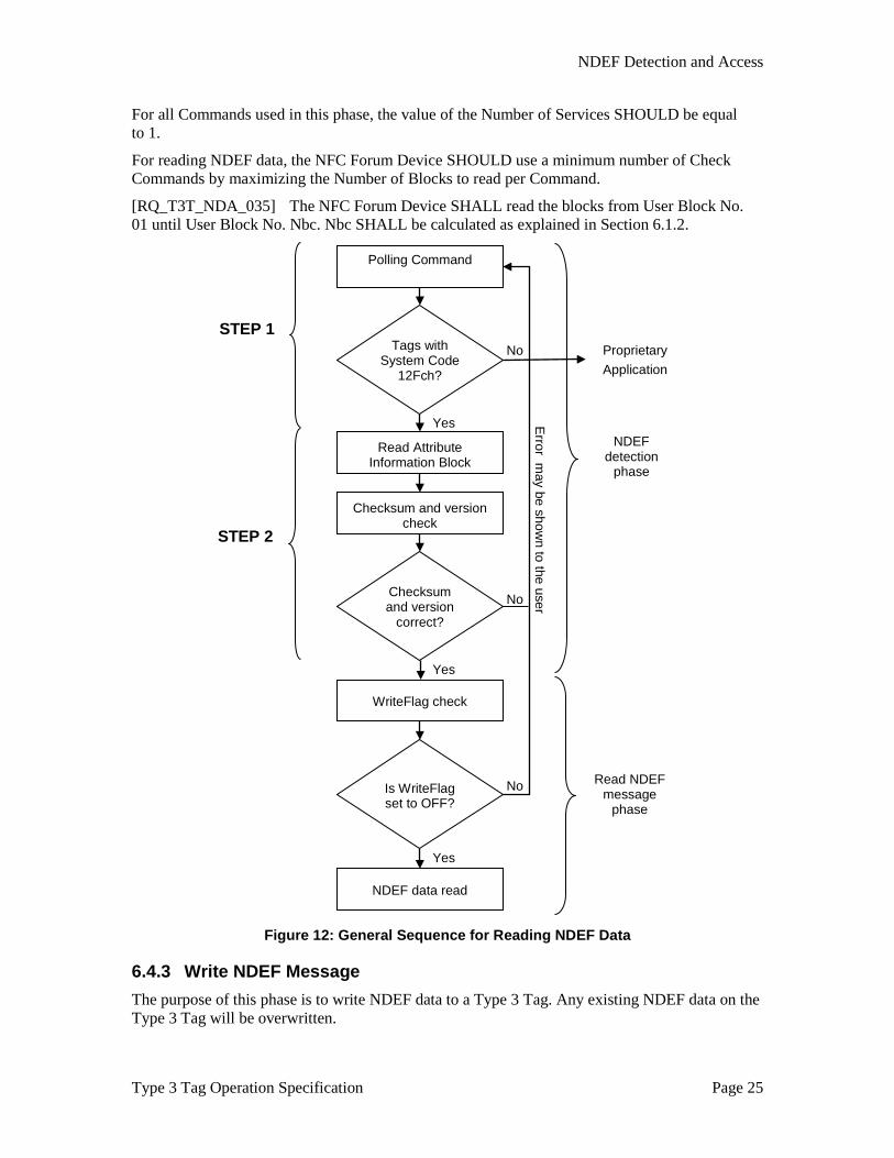
6.4.1 NDEF Detection NDEF data in the Type 3 Tag MAY be detected by the NFC Forum Device as follows:
STEP 1:
The first step to detect NDEF-enabled Type 3 Tags consists of the detection of Type 3 Tags in the RF field having a System Code of 12FCh.
The NFC Forum Device sends a Polling Command with System Code 12FCh. NDEF-enabled Type 3 Tags respond to the Polling Command by sending a Polling Response including IDm and PMm.
If there is at least one Type 3 Tag with System Code 12FCh in the field, go to STEP 2; otherwise, repeat STEP 1.
INITIALIZED READ/WRITE
READ ONLY
Update
Update

NDEF Detection and Access
Type 3 Tag Operation Specification Page 24
Figure 11: General Sequence for Detecting NDEF Data
STEP 2:
[RQ_T3T_NDA_029] If there is more than one NDEF-enabled Type 3 Tag in the field, the NFC Forum Device SHALL select one of them for this step. The NFC Forum Device MAY perform step 2 sequentially for each NDEF-enabled Type 3 Tag.
[RQ_T3T_NDA_030] The NFC Forum Device SHALL read the Attribute Information data using the Check Command. For the Check Command, the NFC Forum Device SHALL use the same IDm that it received in the Polling Response from the Type 3 Tag.
The value of the Number of Services SHOULD be equal to 1.
[RQ_T3T_NDA_031] The Attribute Information data contains a checksum to confirm that the Attribution Information data is valid. The NFC Forum Device SHALL validate the checksum.
[RQ_T3T_NDA_032] The NFC Forum Device SHALL check if it supports the NDEF mapping version number based on the rules given in Section 6.1.3.
If the checksum is correct and the NFC Forum Device supports the NDEF mapping version, the NFC Forum Device MAY proceed with:
• The read NDEF message phase, or
• The write NDEF message phase
[RQ_T3T_NDA_033] If the checksum is not correct or the NFC Forum Device does not support the NDEF mapping version, the NFC Forum Device SHALL NOT read or write NDEF data to this Type 3 Tag.
If the Attribute Information data is valid, the NFC Forum Device knows the parameters Nbr, Nbw, Nmaxb, RWflag, and Ln.
If the value of Ln is greater than 0, the Type 3 Tag contains NDEF data.
6.4.2 Read NDEF Message The purpose of this phase is to read the data blocks containing NDEF data in order to assemble the NDEF data structure stored on the Type 3 Tag.
[RQ_T3T_NDA_034] For all Commands, the NFC Forum Device SHALL use the same IDm that was used during the NDEF detection phase for the selected Type 3 Tag.
Tags with System Code
12FCh?
Sequence for reading or writing NDEF data
Polling Command
No
Yes
Sequence for proprietary FeliCa application
NDEF Detection and Access
Type 3 Tag Operation Specification Page 25
For all Commands used in this phase, the value of the Number of Services SHOULD be equal to 1.
For reading NDEF data, the NFC Forum Device SHOULD use a minimum number of Check Commands by maximizing the Number of Blocks to read per Command.
[RQ_T3T_NDA_035] The NFC Forum Device SHALL read the blocks from User Block No. 01 until User Block No. Nbc. Nbc SHALL be calculated as explained in Section 6.1.2.
Figure 12: General Sequence for Reading NDEF Data
6.4.3 Write NDEF Message The purpose of this phase is to write NDEF data to a Type 3 Tag. Any existing NDEF data on the Type 3 Tag will be overwritten.
No
No
No
Polling Command
Tags with System Code
12Fch?
Read Attribute Information Block
Checksum and version check
Checksum and version
correct?
WriteFlag check
Is WriteFlag set to OFF?
NDEF data read
STEP 1
STEP 2
Yes
Yes
Yes
Proprietary Application
NDEF detection
phase
Read NDEF message
phase
Error m
ay be shown to the user

NDEF Detection and Access
Type 3 Tag Operation Specification Page 26
[RQ_T3T_NDA_036] For all Commands, the NFC Forum Device SHALL use the same IDm that was used during the NDEF detection phase for the selected Type 3 Tag.
For all Commands used in this phase, the value of the Number of Services SHOULD be equal to 1.
For writing NDEF data, the NFC Forum Device SHOULD use a minimum number of Update Commands by maximizing the Number of Blocks to write per Command.
[RQ_T3T_NDA_037] The NFC Forum Device SHALL check the RWFlag and only attempt to write if its value is 01h.
Before writing NDEF data, the NFC Forum Device MAY check if the NDEF data size is smaller than the maximum memory size for NDEF data available on the Type 3 Tag.
[RQ_T3T_NDA_038] In this case, the NFC Forum Device SHALL calculate the maximum memory size for NDEF by multiplying Nmaxb times 16.
[RQ_T3T_NDA_039] Before writing NDEF data, the NFC Forum Device SHOULD update the Attribute Information with the WriteFlag set to ON.
[RQ_T3T_NDA_040] The NFC Forum Device SHALL start writing the blocks from User Block No. 01 until User Block No. Nbc. The number of blocks to use for NDEF data (Nbc) SHALL satisfy Nbc<= Nmaxb.
[RQ_T3T_NDA_041] After writing the NDEF data, the NFC Forum Device SHALL write updated Attribute Information data to User Block No. 00 using the Update Command.
[RQ_T3T_NDA_042] The Length information within the Attribute Information SHALL be changed according to the amount of NDEF data written.
[RQ_T3T_NDA_043] The WriteFlag SHALL be set to OFF.

NDEF Detection and Access
Type 3 Tag Operation Specification Page 27
Figure 13: General Sequence for Writing NDEF Data
6.4.4 State Changes A state change from “INITIALIZED” to “READ/WRITE” can be performed by writing a valid NDEF message to the Type 3 Tag as described in Section 6.4.3.
A state change from “READ/WRITE” to “INITIALIZED” can be performed by updating the attribute information block with an Ln value of 0.
No
No
Polling Command
Tags with System Code
12Fch?
Read Attribute Information Block
Checksum and version check
Checksum and version
correct?
Set WriteFlag to ON
Write Attribute Information Block
(WriteFlag set to OFF)
STEP 1
STEP 2
Yes
Yes
Proprietary Application
NDEF detection
phase
Write NDEF message
phase
Error m
ay be shown to the user
NDEF data write

Typical Activation Sequence
Type 3 Tag Operation Specification Page 28
A. Typical Activation Sequence This appendix is informative, outlining the typical activation sequence from the point of view of a standalone NFC Forum Device implementation.
The communication between the NFC Forum Device and the Type 3 Tag is initiated as follows:
1. The NFC Forum Device switches on the RF field. The NFC Forum Device sends a Polling Command. The NFC Forum Device should wait for at least 20 milliseconds after switching the RF field on before sending a Polling Command.
2. The NFC Forum Device waits to receive Polling Responses from the Type 3 Tags in the field. If the NFC Forum Device fails to receive a Polling Response, then the NFC Forum Device may send a Polling Command again.
3. Each Polling Response contains the IDm information of the sending Type 3 Tag, which can be used by the NFC Forum Device as part of the Check and Update Commands to further communicate with the Type 3 Tag. The NFC Forum Device may communicate with multiple Type 3 Tags using their respective IDm values.

Revision History
Type 3 Tag Operation Specification Page 29
B. Revision History The following table outlines the revision history of Type 3 Tag Operation Specification.
Table 12: Revision History
Document Name Revision and Release Date
Status Change Notice Supersedes
Type 3 Tag Operation Specification
Version 1.0, July 2007
Final None
Type 3 Tag Operation Specification
Version 1.1, June 2011
Final Alignment with Digital and Activity specification, fixed errata, editorial improvements; editorial updates for Figures 2 and 8
Version 1.0, July 2007