nexans euromold interface a 200 series screened cable connectors
TRANSCRIPT
Catalogue 2015
a Nexans company


1
Nexans Network SolutionsDiv. Euromold
COMPANY PRESENTATION
While every care is taken to ensure that the information contained in this publication is correct, no legal responsibility can be accepted for any inaccuracy. Nexans Network Solutions N.V. - Div. Euromold reserves the right to alter or modify the characteristics of its products described in this catalogue as standards and technology evolve.
EUROMOLDEuromold is the leading European specialised designer, manufacturer and distributor of prefabricated cable accessories for medium voltage energy distribution. Euromold provides a complete range of accessories for underground cables: premoulded EPDM rubber connectors for cables and epoxy bushings for transformers and switchgear, as well as a large range of cold-shrinkable terminations and joints from 12 to 42 kV.Euromold is also the manufacturer of electrical components for the high voltage accessories of the Nexans group.
ISO 9001 CertificateSince 1992, Euromold’s commitment to quality is demonstrated by its ISO 9001 certification.
Laboratory accreditationSince June 2000, Euromold’s independent ELAB laboratory obtained the BELAC accreditation no.144-TEST conform with the European standards for laboratories ISO 17025 for electrical testing of low and medium voltage cable accessories according to the international standards EN 50393, IEC 60502-4, IEC 61442 and HD 629.
International standardsAll our products meet the International standards like CENELEC HD 629.1, CENELEC EN 50180, IEC 60137, IEC 60502-4… or country speci-fications. Official certificates, CESI, KEMA, ATEX… prove the conformity of our products. Long duration tests of existing or new products are continuously performed in our test fields.

2
05/2
015
SEPARABLE CONNECTORSAND BUSHINGS
INTERFACE A
Table of contents158LR - elbow connector152SR - straight connector151SP - straight plug156SA - surge arrester 180AR-1 /-2 /-3 and 180AR-1-G /-3-G - equipment bushings250SFR-P - equipment bushing180A-24P-O - in-air bushingPITO-E - plug-in terminationAccessoriesBail restraints
Interface A1Dimensions according to European CENELEC EN 50180 and 50181 (in mm).
48 0-0.2
Dia. 48.5±0.2
Dia. 32.5±0.2
Dia. forpin 7.9+0.02
- 0.05
Dia. 31+0.1 - 0.3
9min
In mm.
3
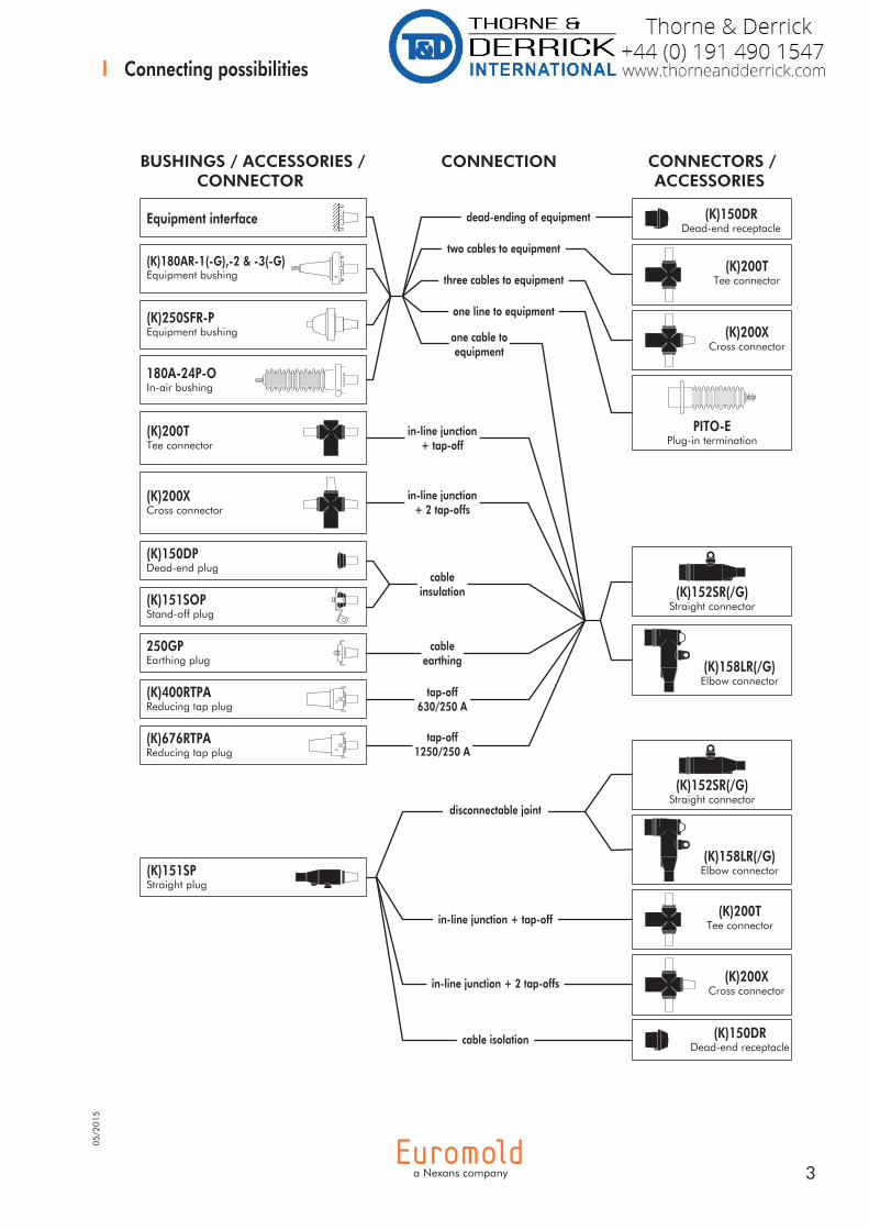
Connecting possibilities
PITO-EPlug-in termination
(K)150DRDead-end receptacle
(K)150DRDead-end receptacle
(K)151SPStraight plug
BUSHINGS / ACCESSORIES /CONNECTOR
CONNECTION CONNECTORS /ACCESSORIES
(K)400RTPAReducing tap plug
(K)151SOPStand-off plug
(K)150DPDead-end plug
cable isolation
in-line junction + 2 tap-offs
tap-off630/250 A
disconnectable joint
in-line junction+ 2 tap-offs
in-line junction+ tap-off
cableinsulation
tap-off1250/250 A
250GPEarthing plug
(K)250SFR-PEquipment bushing
(K)180AR-1(-G),-2 & -3(-G)Equipment bushing
Equipment interface
cableearthing
(K)200TTee connector
(K)200XCross connector
(K)200TTee connector
one cable toequipment
(K)200XCross connector
(K)200TTee connector
(K)200XCross connector
in-line junction + tap-off
dead-ending of equipment
two cables to equipment
one line to equipment
three cables to equipment
(K)676RTPAReducing tap plug
(K)152SR(/G)Straight connector
(K)158LR(/G)Elbow connector
(K)152SR(/G)Straight connector
180A-24P-OIn-air bushing
(K)158LR(/G)Elbow connector
05/2
015
4
05/2
015
Specifications and standardsThe separable connector 158LR meets the requirements of CENELEC HD 629.1.
Up to 24 kV - 250 A
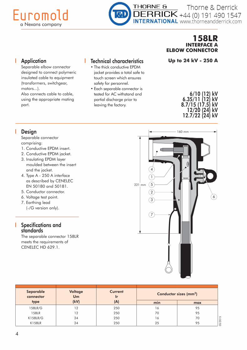
DesignSeparable connector comprising:1. Conductive EPDM insert.2. Conductive EPDM jacket.3. Insulating EPDM layer moulded between the insert and the jacket.4. Type A - 250 A interface as described by CENELEC EN 50180 and 50181.5. Conductor connector.6. Voltage test point.7. Earthing lead (-/G version only).
158LRINTERFACE A
ELBOW CONNECTOR
ApplicationSeparable elbow connector designed to connect polymeric insulated cable to equipment (transformers, switchgear, motors...).Also connects cable to cable, using the appropriate mating part.
6/10 (12) kV6.35/11 (12) kV
8.7/15 (17.5) kV12/20 (24) kV
12.7/22 (24) kV
Technical characteristics • The thick conductive EPDM
jacket provides a total safe to touch screen which ensures safety for personnel.
• Each separable connector is tested for AC withstand and partial discharge prior to leaving the factory.
Separable connector
type
VoltageUm(kV)
CurrentIr
(A)
Conductor sizes (mm2)
min max158LR/G
158LR
K158LR/G
K158LR
12
12
24
24
250
250
250
250
16
70
16
25
95
95
70
95
6
1
3
2
7
221 mm
160 mm
4
5

5
For adaptedbail restraints:
see 'Bail restraints and typical applications'.
For outdoorapplications.
Order: +MWS.
Components can be ordered individually.
For use withcopper tape
screened cables. Order: Kit MT.
For use with Alupe orC 33-226 cables.
Please contact our representative.
For use withother cable types.
Please contact our representative.
The kit also comprises lubricant, wipers, installation instructions and crimp chart.
Ordering instructionsSelect the part number which gives the best centring to the cable core insulation diameter and substitute X using table X, according to the conductor size and type.Add a 'K' for use up to 24 kV.
Example:The copper wire screened cable is 24 kV, 50 mm2 stranded aluminium with a diameter over core insulation of 20.4 mm.Order a K158LR-FG-50(K)M-12-2+11TL elbow connector kit.
For an option with a bolted conductor contact,specify the ordering part number below.
Conductorsizes
(mm²)
Aluminium Copper
DIN hexagonal Deep indent DIN hexagonal
162535507095
- 25(K)M-12-2 35(K)M-12-2 50(K)M-12-2 70(K)M-12-2 95(K)M-12-2 *
-25KM-12-135KM-12-1
50(K)M-12-1*70(K)M-12-1*95(K)M-12-1*
16(K)M-11-225(K)M-11-235(K)M-11-250(K)M-11-270(K)M-11-295(K)M-11-2
Table X
Conductor
contact
164LRC-Xor
164LRMC-X
Pin contact
+ hex key
154LRF
Bail
restraint
150BA-B1
Connector housing
(K)158BLR-W
(K)158LR-W-X+11TL
connector kit for
larger sizesCable adaptor
11TL
Connector housing
(K)158BLR/G-WCable reducer
211CA
(K)158LR/G-W-Xconnector kit for
smaller sizes
Kit contentsThe complete (K)158LR or (K)158LR/G elbow connector kit comprises the following components:
* The 158LR-FB is not compatible with these conductor contacts.
Orderingpart number
Dia. over core insulation (mm)
min max
158LR/G-11-X158LR/G-13-X
158LR-FB-X+11TL158LR-FG-X+11TL158LR-GA-X+11TL158LR-GAB-X+11TL158LR-GH-X+11TL
12.614.617.518.419.721.023.6
16.118.720.221.222.523.826.4
Table W
Ordering part number Dia. over core insulation (mm) Conductor sizes (mm²)
158LR/G-13-25.95-14-5
158LR-GAS-50.95-14-5+11TL
14.6 - 22.7
19.7 - 25.4
35 - 70
25 - 95
6
05/2
015
Up to 24 kV - 250 A
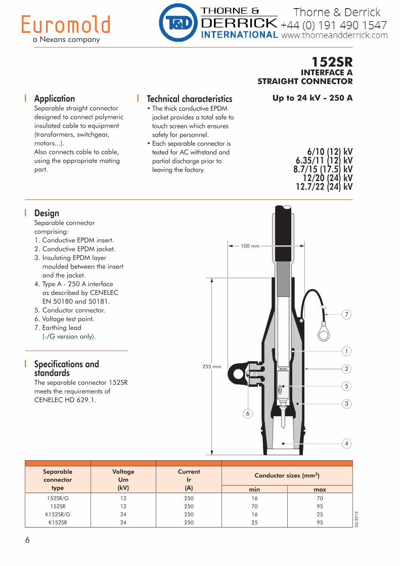
152SRINTERFACE A
STRAIGHT CONNECTOR
6/10 (12) kV6.35/11 (12) kV
8.7/15 (17.5) kV12/20 (24) kV
12.7/22 (24) kV
ApplicationSeparable straight connector designed to connect polymeric insulated cable to equipment (transformers, switchgear, motors...).Also connects cable to cable, using the appropriate mating part.
Technical characteristics • The thick conductive EPDM
jacket provides a total safe to touch screen which ensures safety for personnel.
• Each separable connector is tested for AC withstand and partial discharge prior to leaving the factory.
Separable connector
type
VoltageUm(kV)
CurrentIr
(A)
Conductor sizes (mm2)
min max152SR/G
152SR
K152SR/G
K152SR
12
12
24
24
250
250
250
250
16
70
16
25
70
95
25
95
255 mm
100 mm
1
2
3
4
6
7
5
Specifications and standardsThe separable connector 152SR meets the requirements of CENELEC HD 629.1.
DesignSeparable connector comprising:1. Conductive EPDM insert.2. Conductive EPDM jacket.3. Insulating EPDM layer moulded between the insert and the jacket.4. Type A - 250 A interface as described by CENELEC EN 50180 and 50181.5. Conductor connector.6. Voltage test point.7. Earthing lead (-/G version only).
7
For adaptedbail restraints:
see 'Bail restraints and typical applications'.
For outdoorapplications.
Order: +MWS.
Components can be ordered individually.
For use withcopper tape
screened cables. Order: Kit MT.
For use with Alupe orC 33-226 cables.
Please contact our representative.
For use withother cable types.
Please contact our representative.
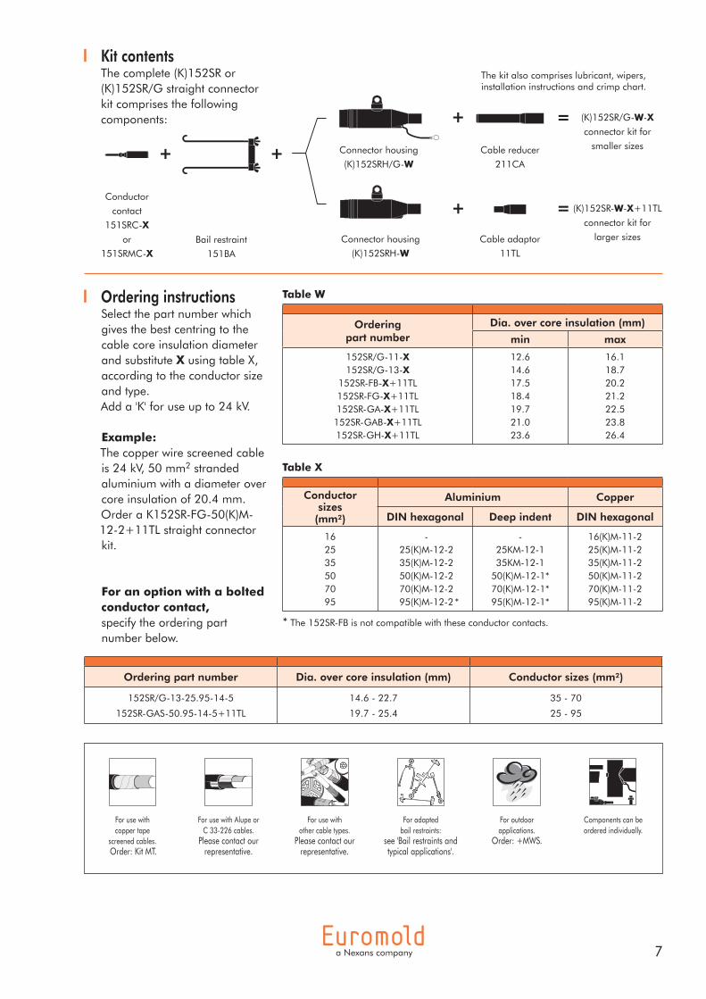
Kit contentsThe complete (K)152SR or (K)152SR/G straight connector kit comprises the following components:
The kit also comprises lubricant, wipers, installation instructions and crimp chart.
Ordering instructionsSelect the part number which gives the best centring to the cable core insulation diameter and substitute X using table X, according to the conductor size and type.Add a 'K' for use up to 24 kV.
Example:The copper wire screened cable is 24 kV, 50 mm2 stranded aluminium with a diameter over core insulation of 20.4 mm.Order a K152SR-FG-50(K)M-12-2+11TL straight connector kit.
For an option with a bolted conductor contact,specify the ordering part number below.
Bail restraint
151BA
Conductor
contact
151SRC-Xor
151SRMC-X
Connector housing
(K)152SRH-WCable adaptor
11TL
Connector housing
(K)152SRH/G-WCable reducer
211CA
(K)152SR/G-W-Xconnector kit for
smaller sizes
(K)152SR-W-X+11TL
connector kit for
larger sizes
* The 152SR-FB is not compatible with these conductor contacts.
Conductorsizes
(mm²)
Aluminium Copper
DIN hexagonal Deep indent DIN hexagonal
162535507095
- 25(K)M-12-2 35(K)M-12-2 50(K)M-12-2 70(K)M-12-2 95(K)M-12-2 *
-25KM-12-135KM-12-1
50(K)M-12-1*70(K)M-12-1*95(K)M-12-1*
16(K)M-11-225(K)M-11-235(K)M-11-250(K)M-11-270(K)M-11-295(K)M-11-2
Table X
Orderingpart number
Dia. over core insulation (mm)
min max
152SR/G-11-X152SR/G-13-X
152SR-FB-X+11TL152SR-FG-X+11TL152SR-GA-X+11TL152SR-GAB-X+11TL152SR-GH-X+11TL
12.614.617.518.419.721.023.6
16.118.720.221.222.523.826.4
Table W
Ordering part number Dia. over core insulation (mm) Conductor sizes (mm²)
152SR/G-13-25.95-14-5
152SR-GAS-50.95-14-5+11TL
14.6 - 22.7
19.7 - 25.4
35 - 70
25 - 95

8
05/2
015
ApplicationSeparable straight plug designed to connect polymeric insulated cable to cable.Mates with the elbow, straight and branch joint connectors.
Up to 24 kV - 200 A
151SPINTERFACE A
STRAIGHT PLUG
6/10 (12) kV6.35/11 (12) kV
8.7/15 (17.5) kV12/20 (24) kV
12.7/22 (24) kV
Technical characteristics • The thick conductive EPDM
jacket provides a total safe to touch screen which ensures safety for personnel.
• Each straight plug is tested for AC withstand and partial discharge prior to leaving the factory.
Separable plugtype
VoltageUm(kV)
CurrentIr
(A)
Conductor sizes (mm2)
min max
151SP
K151SP
12
24
200
200
16
16
95
95
223 mm
Dia. 54 mm
2
1
3
4
5
DesignSeparable connector comprising:1. Conductive EPDM insert.2. Conductive EPDM jacket.3. Insulating EPDM layer moulded between the insert and the jacket.4. Type A interface as described by CENELEC EN 50180 and 50181.5. Conductor connector.
9
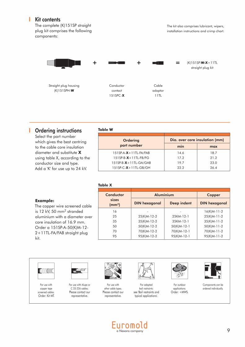
Kit contentsThe complete (K)151SP straight plug kit comprises the following components:
The kit also comprises lubricant, wipers,
installation instructions and crimp chart.
Straight plug housing
(K)151SPH-WConductor
contact
151SPC-X
Cable
adaptor
11TL
(K)151SP-W-X+11TL
straight plug kit
Ordering instructionsSelect the part numberwhich gives the best centring to the cable core insulation diameter and substitute X using table X, according to the conductor size and type.Add a 'K' for use up to 24 kV.
Example:The copper wire screened cable is 12 kV, 50 mm2 stranded aluminium with a diameter over core insulation of 16.9 mm.Order a 151SP-A-50(K)M-12-2+11TL-FA/FAB straight plug kit.
Table X
Table W
For adaptedbail restraints:
see 'Bail restraints and typical applications'.
For outdoorapplications.
Order: +MWS.
Components can be ordered individually.
For use withcopper tape
screened cables. Order: Kit MT.
For use with Alupe orC 33-226 cables.
Please contact our representative.
For use withother cable types.
Please contact our representative.
Conductorsizes
(mm²)
Aluminium Copper
DIN hexagonal Deep indent DIN hexagonal
16
25
35
50
70
95
-
25(K)M-12-2
35(K)M-12-2
50(K)M-12-2
70(K)M-12-2
95(K)M-12-2
-
25KM-12-1
35KM-12-1
50(K)M-12-1
70(K)M-12-1
95(K)M-12-1
16(K)M-11-2
25(K)M-11-2
35(K)M-11-2
50(K)M-11-2
70(K)M-11-2
95(K)M-11-2
Orderingpart number
Dia. over core insulation (mm)
min max
151SP-A-X+11TL-FA/FAB
151SP-B-X+11TL-FB/FG
151SP-B-X+11TL-GA/GAB
151SP-C-X+11TL-GB/GH
14.6
17.2
19.7
22.2
18.7
21.2
23.0
26.4
10
05/2
015
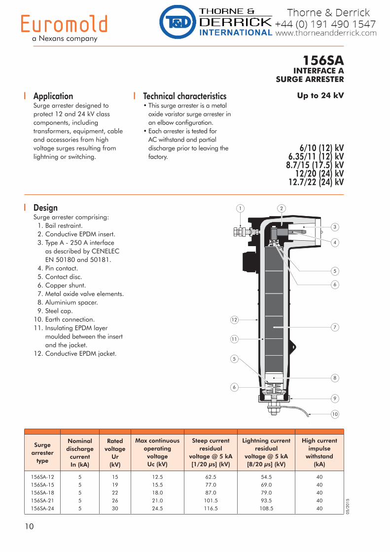
ApplicationSurge arrester designed to protect 12 and 24 kV class components, including transformers, equipment, cable and accessories from high voltage surges resulting from lightning or switching.
Up to 24 kV
156SAINTERFACE A
SURGE ARRESTER
Technical characteristics • This surge arrester is a metal
oxide varistor surge arrester in an elbow configuration.
• Each arrester is tested for AC withstand and partial discharge prior to leaving the factory.
6/10 (12) kV6.35/11 (12) kV
8.7/15 (17.5) kV12/20 (24) kV
12.7/22 (24) kV
DesignSurge arrester comprising: 1. Bail restraint. 2. Conductive EPDM insert. 3. Type A - 250 A interface as described by CENELEC EN 50180 and 50181. 4. Pin contact. 5. Contact disc. 6. Copper shunt. 7. Metal oxide valve elements. 8. Aluminium spacer. 9. Steel cap. 10. Earth connection. 11. Insulating EPDM layer moulded between the insert and the jacket. 12. Conductive EPDM jacket.
9
10
8
6
5
11
12
1 2
3
4
5
6
7
Surgearrester
type
Nominal discharge
current In (kA)
Rated voltage
Ur(kV)
Max continuousoperatingvoltageUc (kV)
Steep currentresidual
voltage @ 5 kA[1/20 µs] (kV)
Lightning currentresidual
voltage @ 5 kA[8/20 µs] (kV)
High currentimpulse
withstand(kA)
156SA-12
156SA-15
156SA-18
156SA-21
156SA-24
5
5
5
5
5
15
19
22
26
30
12.5
15.5
18.0
21.0
24.5
62.5
77.0
87.0
101.5
116.5
54.5
69.0
79.0
93.5
108.5
40
40
40
40
40
11
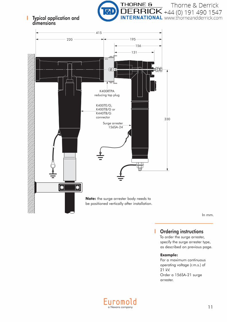
Typical application anddimensions
Ordering instructionsTo order the surge arrester, specify the surge arrester type, as described on previous page.
Example:For a maximum continuous operating voltage (r.m.s.) of 21 kV.Order a 156SA-21 surge arrester.
330
K400RTPAreducing tap plug
220 195
156
131
415
Surge arrester156SA-24
K400TE/G,K400TB/G orK440TB/Gconnector
In mm.
Note: the surge arrester body needs to be positioned vertically after installation.
12
05/2
015
Up to 24 kV - 250 A
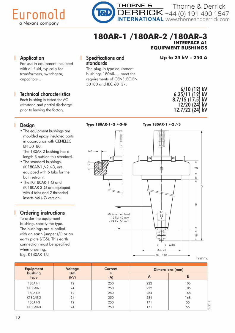
Equipmentbushing
type
VoltageUm(kV)
CurrentIr
(A)
Dimensions (mm)
A B
180AR-1
K180AR-1
180AR-2
K180AR-2
180AR-3
K180AR-3
12
24
12
24
12
24
250
250
250
250
250
250
222
222
284
284
171
171
106
106
168
168
55
55
180AR-1 /180AR-2 /180AR-3INTERFACE A1
EQUIPMENT BUSHINGS
ApplicationFor use in equipment insulated with oil fluid, typically for transformers, switchgear, capacitors...
6/10 (12) kV6.35/11 (12) kV
8.7/15 (17.5) kV12/20 (24) kV
12.7/22 (24) kV
Design• The equipment bushings are
moulded epoxy insulated parts in accordance with CENELEC EN 50180.
The 180AR-2 bushing has a length B outside this standard.
• The standard bushings, (K)180AR-1 /-2 /-3, are equipped with 6 tabs for the bail restraint.
• The (K)180AR-1-G and (K)180AR-3-G are equipped
with 4 tabs and 2 threaded inserts M6 (-G version).
Technical characteristics Each bushing is tested for AC withstand and partial discharge prior to leaving the factory.
Ordering instructionsTo order the equipment bushing, specify the type.The bushings are supplied with an earth jumper (/J) or an earth plate (/GS). This earth connection must be specified when ordering.E.g. K180AR-1/J.
Specifications and standardsThe plug-in type equipment bushings 180AR-… meet the requirements of CENELEC EN 50180 and IEC 60137.
Type 180AR-1-G /-3-G Type 180AR-1 /-2 /-3
In mm.
11
B
A
28
8
19
Dia. 110
Dia. 75
Minimum oil level:- 12 kV: 40 mm- 24 kV: 50 mm
M10
M6
Dia.16
13
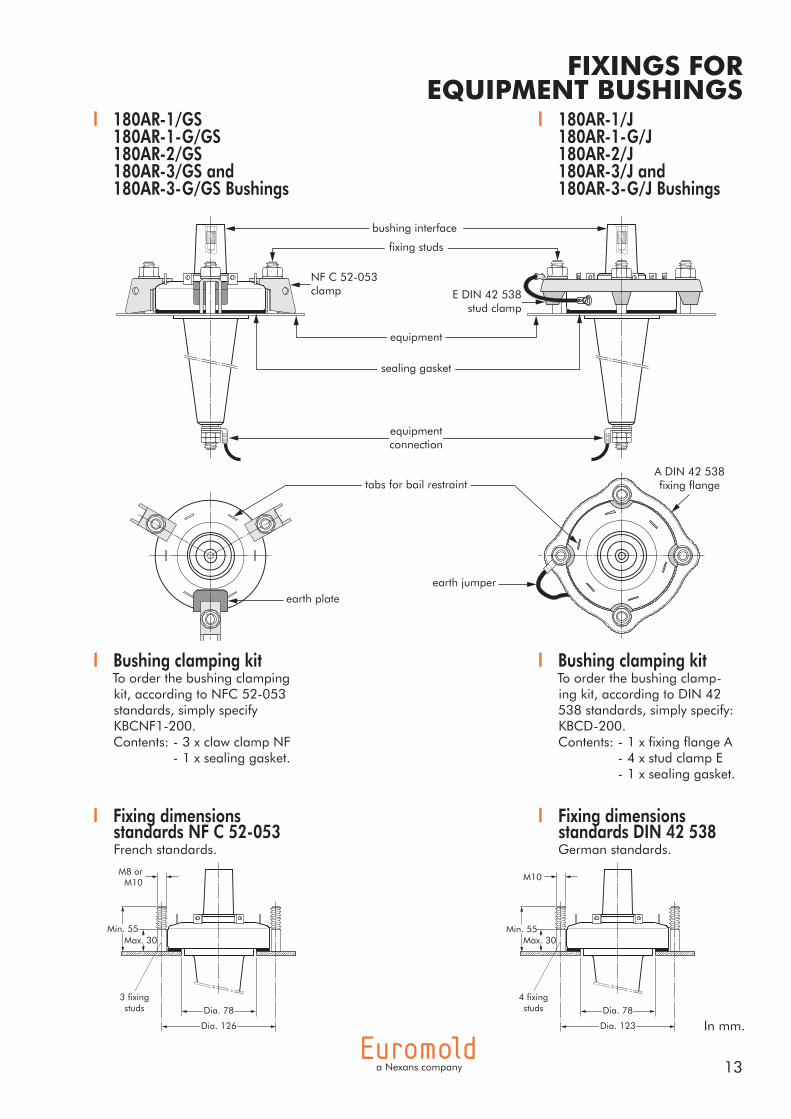
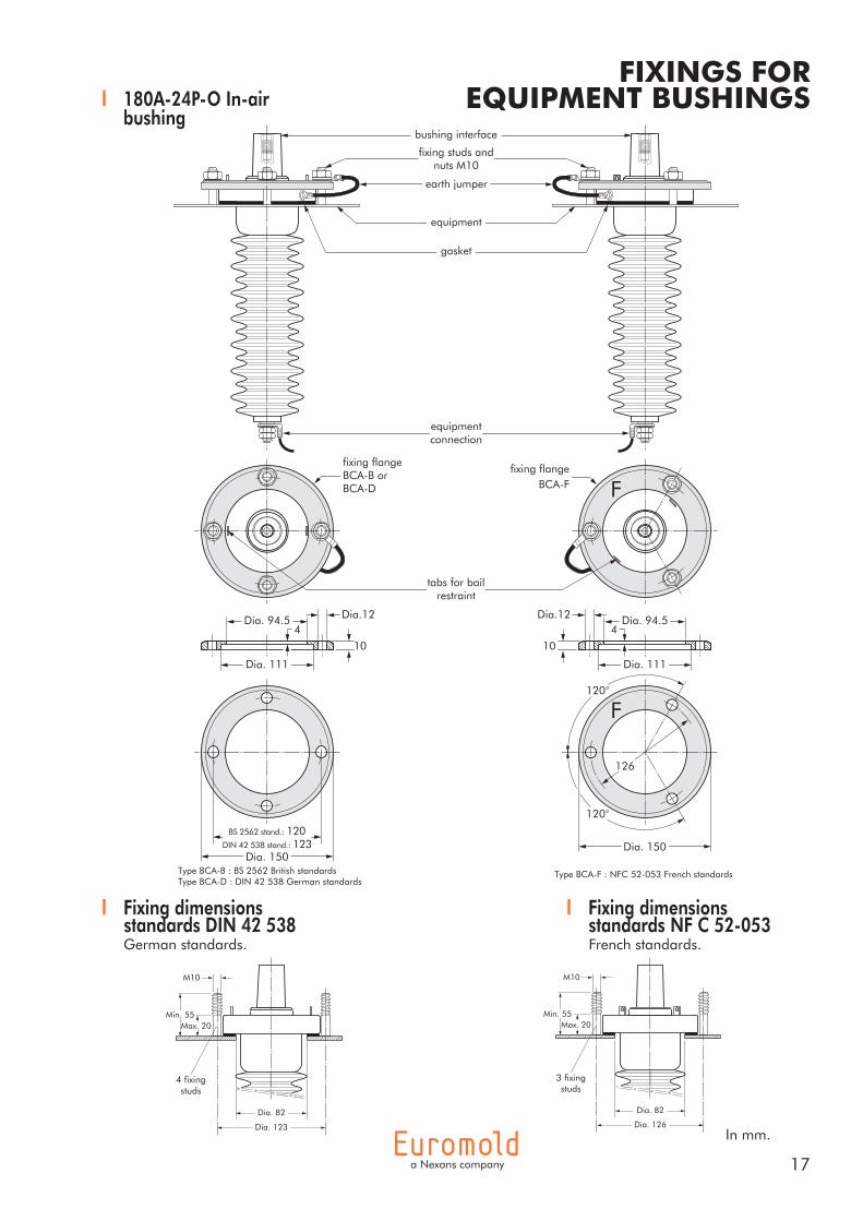
FIXINGS FOR EQUIPMENT BUSHINGS
180AR-1/J 180AR-1-G/J 180AR-2/J 180AR-3/J and 180AR-3-G/J Bushings
180AR-1/GS 180AR-1-G/GS 180AR-2/GS 180AR-3/GS and 180AR-3-G/GS Bushings
Bushing clamping kitTo order the bushing clamping kit, according to NFC 52-053 standards, simply specify KBCNF1-200.Contents: - 3 x claw clamp NF - 1 x sealing gasket.
Bushing clamping kitTo order the bushing clamp-ing kit, according to DIN 42 538 standards, simply specify: KBCD-200.Contents: - 1 x fixing flange A - 4 x stud clamp E - 1 x sealing gasket.
Fixing dimensions standards NF C 52-053French standards.
Fixing dimensions standards DIN 42 538German standards.
In mm.
M10
4 fixingstuds Dia. 78
Dia. 123
M8 orM10
3 fixingstuds
Min. 55
Dia. 78
Dia. 126
Max. 30Min. 55
Max. 30
earth jumper
A DIN 42 538fixing flange
earth plate
sealing gasket
equipment
fixing studs
bushing interface
E DIN 42 538stud clamp
NF C 52-053clamp
tabs for bail restraint
equipment connection
14
05/2
015
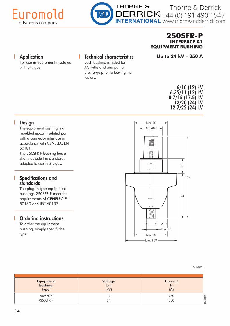
Up to 24 kV - 250 A
250SFR-PINTERFACE A1
EQUIPMENT BUSHING
ApplicationFor use in equipment insulated with SF6 gas.
6/10 (12) kV6.35/11 (12) kV
8.7/15 (17.5) kV12/20 (24) kV
12.7/22 (24) kV
DesignThe equipment bushing is a moulded epoxy insulated part with a connector interface in accordance with CENELEC EN 50181. The 250SFR-P bushing has a shank outside this standard, adapted to use in SF6 gas.
Technical characteristics Each bushing is tested forAC withstand and partialdischarge prior to leaving thefactory.
Ordering instructionsTo order the equipment bushing, simply specify the type.
Specifications and standardsThe plug-in type equipment bushings 250SFR-P meet the requirements of CENELEC EN 50180 and IEC 60137.
In mm.
Equipmentbushing
type
VoltageUm(kV)
CurrentIr
(A)
250SFR-P
K250SFR-P
12
24
250
250
Dia. 70
95
31
174
Dia. 109
M10
Dia. 20
Dia. 70
Dia. 48.5
15
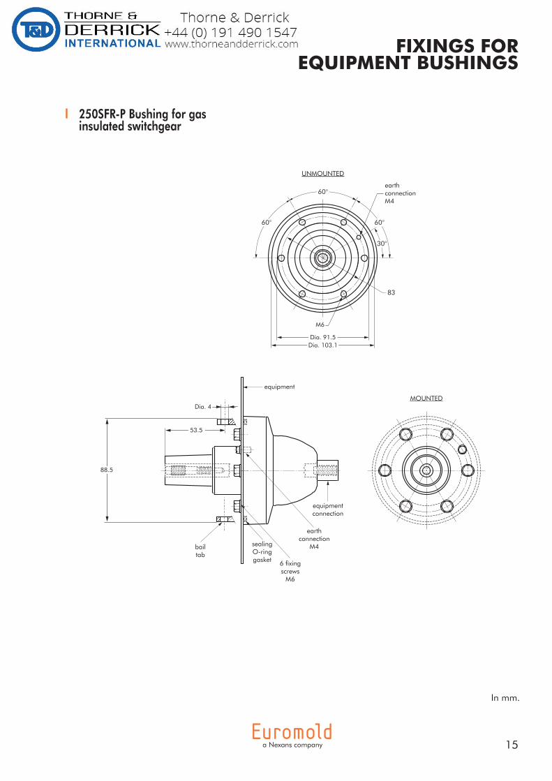
FIXINGS FOR EQUIPMENT BUSHINGS
250SFR-P Bushing for gas insulated switchgear
In mm.
equipment
MOUNTED
6 fixingscrews
M6
sealingO-ringgasket
bailtab
equipmentconnection
earthconnection
M4
30°
UNMOUNTED
60°
60°60°
Dia. 91.5Dia. 103.1
83
M6
earthconnectionM4
53.5
88.5
Dia. 4

16
05/2
015
180A-24P-OINTERFACE A1
IN-AIR BUSHING
Up to 24 kV - 250 AApplicationFor use in equipment insulated with air, typically for dry type transformers, motors, switchgear, capacitors...
Technical characteristics Each bushing is tested forAC withstand and partialdischarge prior to leaving thefactory.
Specifications and standardsThe plug-in type equipment bushings 180A-24P-O are moulded epoxy insulated parts and meet the requirements of CENELEC EN 50181, IEC 60071 and IEC 60137.
6/10 (12) kV6.35/11 (12) kV
8.7/15 (17.5) kV12/20 (24) kV
12.7/22 (24) kV
Equipmentbushing
type
VoltageUm(kV)
CurrentIr
(A)
Creepage distanceA-B
(mm)
180A-24P-O
180A-24P-O
12
24
250
250
630
630
Ordering instructionsTo order the equipment bushing, specify the type.The bushings are supplied with an earth jumper.To include the ring clamp, add:• /B, if per British standards• /D, if per German standards• /F, if per French standards.E.g. 180A-24P-O/F.
In mm.
59
Dia. 80
351
250
M10
Dia. 70
Dia. 110
20
20
B
A
Dia.16
17
180A-24P-O In-air bushing
In mm.
FIXINGS FOR EQUIPMENT BUSHINGS
10
Dia.12
Type BCA-B : BS 2562 British standardsType BCA-D : DIN 42 538 German standards
4
F
120°
120°
Type BCA-F : NFC 52-053 French standards
fixing studs andnuts M10
bushing interface
earth jumper
equipment
gasket
equipmentconnection
tabs for bailrestraint
fixing flangeBCA-B orBCA-D
fixing flangeBCA-F
Dia. 94.5
Dia. 111
BS 2562 stand.: 120DIN 42 538 stand.: 123
Dia. 150Dia. 150
10
Dia.124
Dia. 94.5
Dia. 111
126
M10
4 fixingstuds
Max. 20Min. 55
Dia. 123
Dia. 82
3 fixingstuds
Max. 20Min. 55
Dia. 126
Dia. 82
M10
Fixing dimensions standards NF C 52-053French standards.
Fixing dimensions standards DIN 42 538German standards.
18
05/2
015
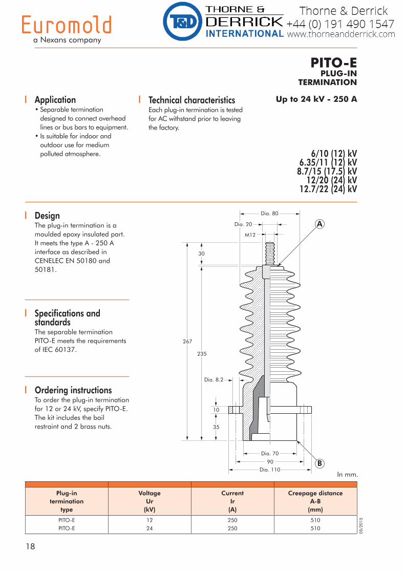
Ordering instructionsTo order the plug-in termination for 12 or 24 kV, specify PITO-E.The kit includes the bail restraint and 2 brass nuts.
Up to 24 kV - 250 A
Plug-intermination
type
VoltageUr
(kV)
CurrentIr
(A)
Creepage distanceA-B
(mm)
PITO-E
PITO-E
12
24
250
250
510
510
DesignThe plug-in termination is a moulded epoxy insulated part. It meets the type A - 250 Ainterface as described in CENELEC EN 50180 and 50181.
PITO-EPLUG-IN
TERMINATION
Application• Separable termination
designed to connect overhead lines or bus bars to equipment.
• Is suitable for indoor and outdoor use for medium polluted atmosphere. 6/10 (12) kV
6.35/11 (12) kV8.7/15 (17.5) kV
12/20 (24) kV12.7/22 (24) kV
Technical characteristics Each plug-in termination is testedfor AC withstand prior to leavingthe factory.
Specifications and standardsThe separable termination PITO-E meets the requirements of IEC 60137.
In mm.
19
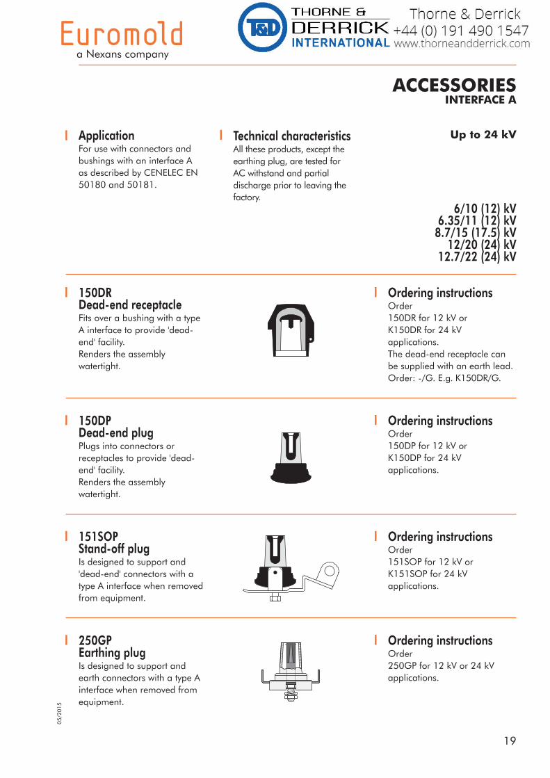
ACCESSORIESINTERFACE A
Up to 24 kVApplicationFor use with connectors and bushings with an interface A as described by CENELEC EN 50180 and 50181.
Technical characteristics All these products, except theearthing plug, are tested forAC withstand and partialdischarge prior to leaving thefactory.
6/10 (12) kV6.35/11 (12) kV
8.7/15 (17.5) kV12/20 (24) kV
12.7/22 (24) kV
250GPEarthing plugIs designed to support and earth connectors with a type A interface when removed from equipment.
Ordering instructionsOrder 250GP for 12 kV or 24 kVapplications.
Ordering instructionsOrder 151SOP for 12 kV orK151SOP for 24 kVapplications.
151SOPStand-off plugIs designed to support and 'dead-end' connectors with a type A interface when removed from equipment.
150DPDead-end plugPlugs into connectors or receptacles to provide 'dead-end' facility.Renders the assembly watertight.
Ordering instructionsOrder 150DP for 12 kV orK150DP for 24 kVapplications.
150DRDead-end receptacleFits over a bushing with a type A interface to provide 'dead-end' facility.Renders the assembly watertight.
Ordering instructionsOrder150DR for 12 kV orK150DR for 24 kVapplications.The dead-end receptacle canbe supplied with an earth lead.Order: -/G. E.g. K150DR/G.
05/2
015
20
05/2
015
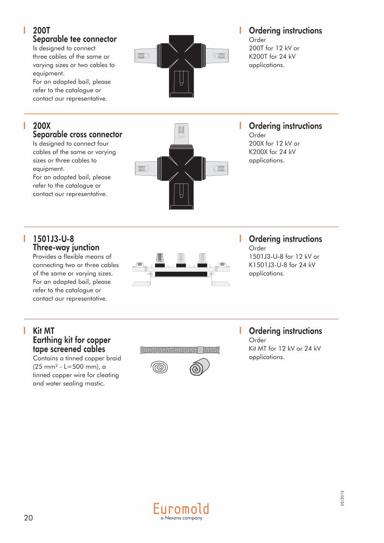
Kit MTEarthing kit for copper tape screened cablesContains a tinned copper braid (25 mm² - L=500 mm), a tinned copper wire for cleating and water sealing mastic.
Ordering instructionsOrder Kit MT for 12 kV or 24 kVapplications.
200XSeparable cross connectorIs designed to connect four cables of the same or varying sizes or three cables to equipment.For an adapted bail, please refer to the catalogue or contact our representative.
Ordering instructionsOrder 200X for 12 kV orK200X for 24 kVapplications.
1501J3-U-8Three-way junctionProvides a flexible means of connecting two or three cables of the same or varying sizes. For an adapted bail, please refer to the catalogue or contact our representative.
Ordering instructionsOrder 1501J3-U-8 for 12 kV orK1501J3-U-8 for 24 kVapplications.
200TSeparable tee connectorIs designed to connect three cables of the same or varying sizes or two cables to equipment.For an adapted bail, please refer to the catalogue or contact our representative.
Ordering instructionsOrder 200T for 12 kV orK200T for 24 kVapplications.
21
BAIL RESTRAINTSINTERFACE A
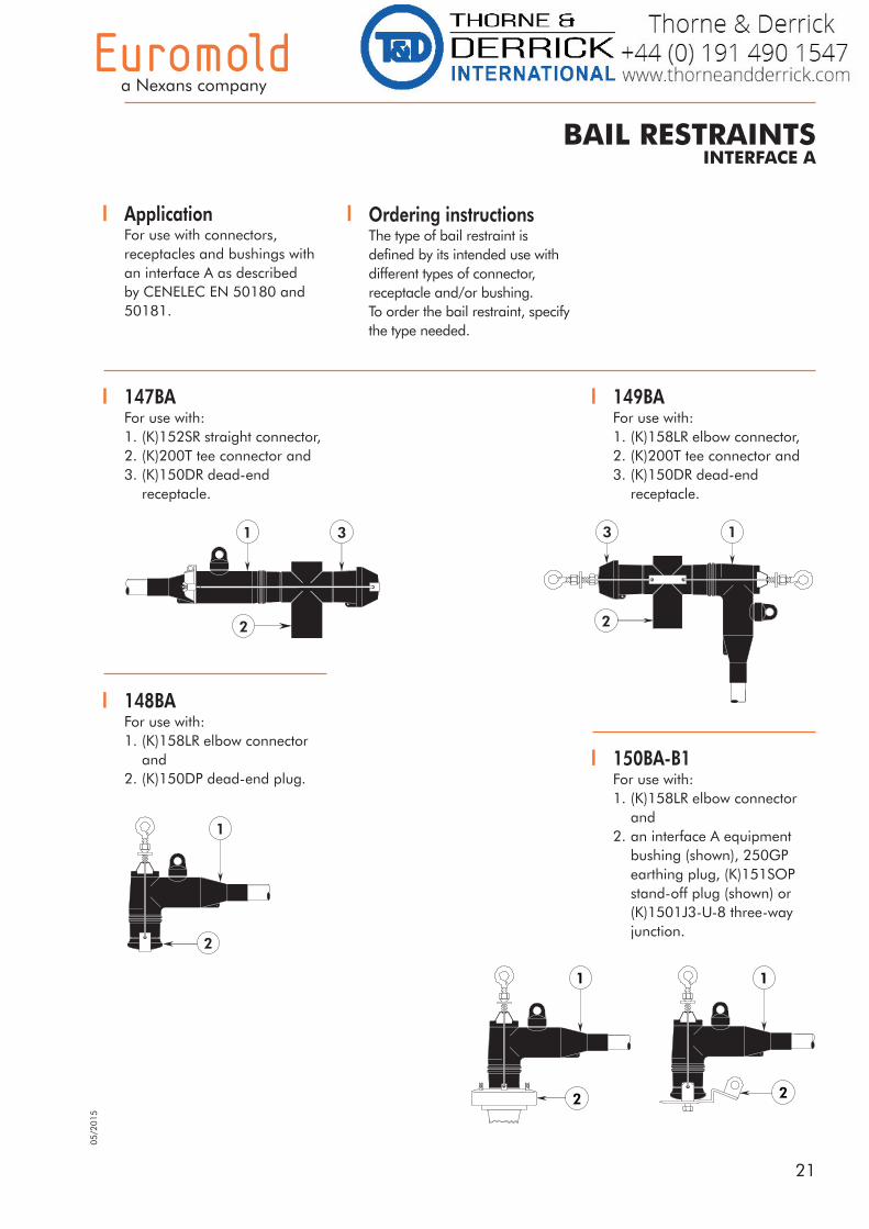
ApplicationFor use with connectors, receptacles and bushings with an interface A as described by CENELEC EN 50180 and 50181.
Ordering instructions The type of bail restraint is defined by its intended use with different types of connector, receptacle and/or bushing.To order the bail restraint, specify the type needed.
149BAFor use with:1. (K)158LR elbow connector,2. (K)200T tee connector and3. (K)150DR dead-end receptacle.
148BAFor use with:1. (K)158LR elbow connector and2. (K)150DP dead-end plug.
147BAFor use with:1. (K)152SR straight connector,2. (K)200T tee connector and3. (K)150DR dead-end receptacle.
150BA-B1For use with:1. (K)158LR elbow connector and2. an interface A equipment bushing (shown), 250GP earthing plug, (K)151SOP stand-off plug (shown) or (K)1501J3-U-8 three-way junction.
1
2
3 1
2
3
1
2
1
2
1
2
05/2
015
22
05/2
015
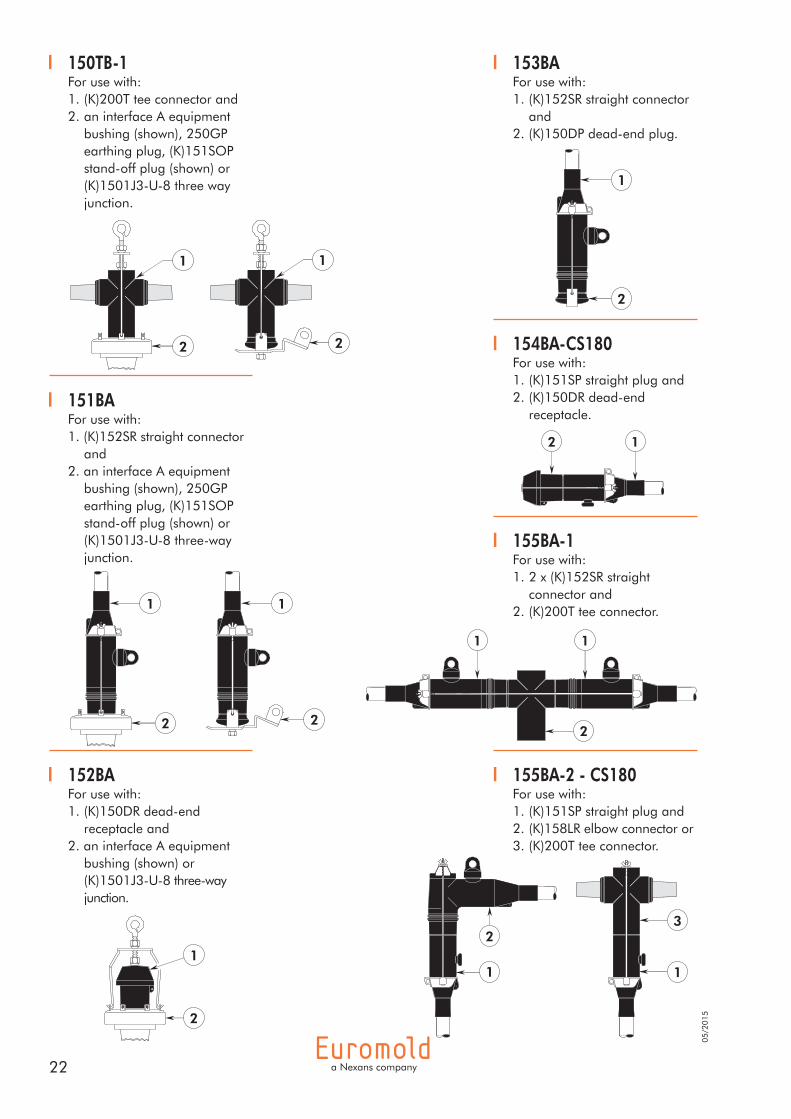
150TB-1For use with:1. (K)200T tee connector and2. an interface A equipment bushing (shown), 250GP earthing plug, (K)151SOP stand-off plug (shown) or (K)1501J3-U-8 three way junction.
151BAFor use with:1. (K)152SR straight connector and2. an interface A equipment bushing (shown), 250GP earthing plug, (K)151SOP stand-off plug (shown) or (K)1501J3-U-8 three-way junction.
153BAFor use with:1. (K)152SR straight connector and2. (K)150DP dead-end plug.
154BA-CS180For use with:1. (K)151SP straight plug and2. (K)150DR dead-end receptacle.
155BA-1For use with:1. 2 x (K)152SR straight connector and2. (K)200T tee connector.
155BA-2 - CS180For use with:1. (K)151SP straight plug and2. (K)158LR elbow connector or 3. (K)200T tee connector.
152BAFor use with:1. (K)150DR dead-end receptacle and2. an interface A equipment bushing (shown) or (K)1501J3-U-8 three-way junction.
1
2
1
2
1
2
1
2
3
11
2
1
2
1
2
1 2
2
1 1
23
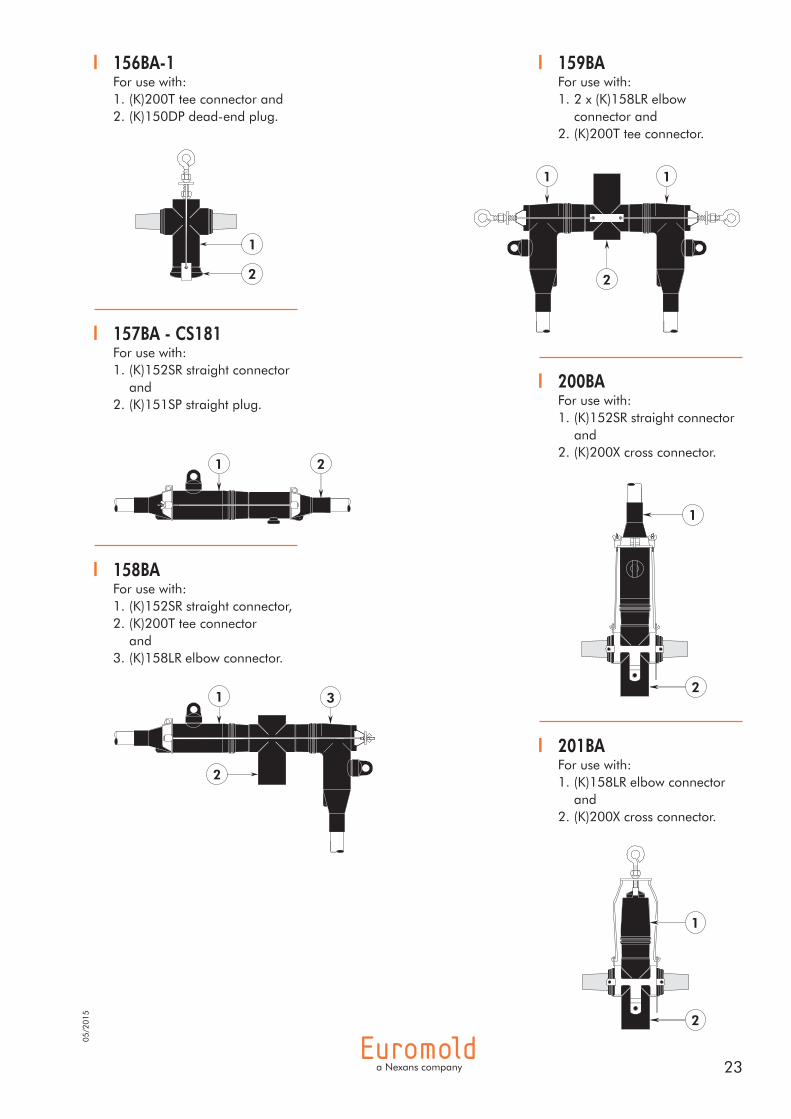
201BAFor use with:1. (K)158LR elbow connector and2. (K)200X cross connector.
159BAFor use with:1. 2 x (K)158LR elbow connector and2. (K)200T tee connector.
157BA - CS181For use with:1. (K)152SR straight connector and2. (K)151SP straight plug.
158BAFor use with:1. (K)152SR straight connector,2. (K)200T tee connector and3. (K)158LR elbow connector.
156BA-1For use with:1. (K)200T tee connector and2. (K)150DP dead-end plug.
200BAFor use with:1. (K)152SR straight connector and2. (K)200X cross connector.
1
2
1
2
1
2
1
2
1
2
3 1
2 1
05/2
015

24
05/2
015
202BAFor use with:1. (K)152SR straight connector,2. (K)200X cross connector and3. (K)150DR dead-end receptacle.
206BAFor use with:1. (K)152SR straight connector,2. (K)200X cross connector and 3. (K)158LR elbow connector.
207BAFor use with:1. 2 x (K)158LR elbow connector and2. (K)200X cross connector.
208BAFor use with:1. (K)200X cross connector and2. (K)150DR dead-end receptacle.
203BAFor use with:1. (K)158LR elbow connector,2. (K)200X cross connector and3. (K)150DR dead-end receptacle.
204BAFor use with:1. (K)200X cross connector and2. (K)151SP straight plug.
205BAFor use with:1. (K)200X cross connector and2. 2 x (K)152SR straight connector.
1
2 2
2
1 1
1
2
1 2
3 1
2
2
3 1 1
2
3


05/2
015
Additional catalogue information on power cable accessoriesis available by contacting us at the address below:
Distributed by:
a Nexans company
Nexans Network Solutions N.V. - Div. Euromold Zuid III, Industrielaan 12, B-9320 Erembodegem
Tel.: +32 (0)53 85 02 11 • [email protected] • www.euromold.be
Catalogue also available on CD-ROM, Website and Mobile Apps