“new shortwave technology from...
TRANSCRIPT

“New Shortwave Technology from Ampegon”

• Ampegon Mini Overview
• New DRM applications :-
• Cost effective information to the high seas!
• Disaster Recovery - DRM to FM rebroadcast
• DRM over SW - Signal coverage and energy advantages
• Updated High Power SW transmitter range (100 – 500kW)
• New fully solid state “low power” Shortwave Transmitter series.TXW-2006-SSATXW-2012-SSATXW-2025-SSA
Contents

8/27/15 3
Heritage of Excellence
Thales Broadcast & Multimedia
Thales Suisse Branch Broadcast
& Multimedia
Thales Broadcast & Multimedia
Thales Suisse Branch Broadcast
& Multimedia
1892
1937
1993 2006 04/2011 11/2012
1st MediumwaveTransmitter
1st MediumwaveTransmitter
Invention of PSM
Invention of PSM
1st Shortwave Transmitter
1st Shortwave Transmitter
500 kW SW PSM TX
500 kW SW PSM TX
Solid State MW TX
Solid State MW TX
Rotatable AntennaRotatable Antenna
DRMDRM
HVPS for FusionResearch
HVPS for FusionResearch
Cancer treatment with Hadrons
Cancer treatment with Hadrons
ABB Infocom
ABB Infocom ThomcastThomcast
Thomson Broadcast & Multimedia
Thomson Broadcast & Multimedia Thomson BroadcastThomson Broadcast
1st Antenna System
1st Antenna System
Digital Low Level RF System
Digital Low Level RF System
Klystron Supply Unit for
Synchrotrons
Klystron Supply Unit for
Synchrotrons
New Activity: Green Technologies
New Activity: Green Technologies
High Power Solid State RF AmplifierHigh Power Solid
State RF AmplifierPulsed Modulator for Free Electron LasersPulsed Modulator for Free Electron Lasers
Invention of EPSM
Invention of EPSM
Serial Resonant Converter
Serial Resonant Converter

Group-Organization
OwnerOwner
Ampegon Antenna Systems GmbH
Schifferstadt
JV Ampegon Broadcast Ltd.
Abuja
Ampegon AG
Turgi
Ampegon S&T Co. Ltd.
Beijing
Ampegon UK Limited
London
Ampegon AG(Australia)
Melbourne
Ampegon PPT GmbH
Dortmund
Sales & Service Offices
8/27/15 4

8/27/15 5
Ampegon Group Product Portfolio
• Photovoltaic (PV) Power Plants
• Development of Project Rights
• RF Amplifiers
• High Voltage Power Supplies & Modulators
• Digital Low Level RF
•Products for Industrial
and Medical Applications
TransmissionSystems
• Shortwave Transmitters
• Medium wave/ Long wave Transmitters
• DRM Equipment
• Broadcast Control Systems
• Transmission Auxiliaries
ScientificApplications
GreenTechnologies
• SW Broadcast Antennas
• LW/MW Broadcast Antennas
• LF/VLF Antennas
• Towers and Masts
AntennaSystems

8/27/15 6
European X-FEL Hamburg, Germany: DESY
• Project Overview Europe‘s longest x-ray source (3.4 km)• Electron energy: 10 GeV to 17.5 GeV, expandable to 20 GeV
• Total costs: 986 M€ (10 beamlines)
• Time planConstruction begin: Summer 2008Commissioning: 2013First experiments: 2014
• Development and delivery of Prototype Klystron Modulator System, 2008 • 12 kV, 2000 A
• 1.7 ms pulse duration at 10 Hz repetition frequency
• 24 switching modules, each providing min. voltage of 545 V
• Design criteria: maximum modularity and maximum redundancy

8/27/15 7
European X-FEL Hamburg, Germany: DESY
• Full system configuration tests of prototype at DESY site including cable, pulse transformer and klystron: 2009 / 2010
• Delivery of 22 units within 2012 / 2013
• Delivery of 7 more units 2013 / 2014
8/27/15 8
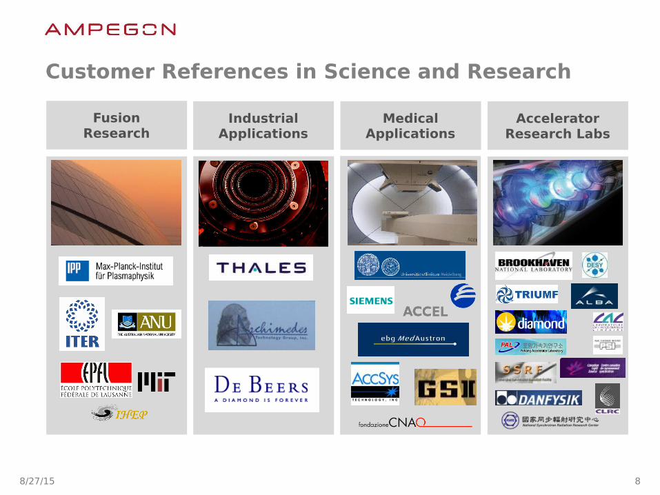
Customer References in Science and Research
FusionResearch
MedicalApplications
AcceleratorResearch Labs
IndustrialApplications

8/27/15 9
Transmission Systems
8/27/15 10
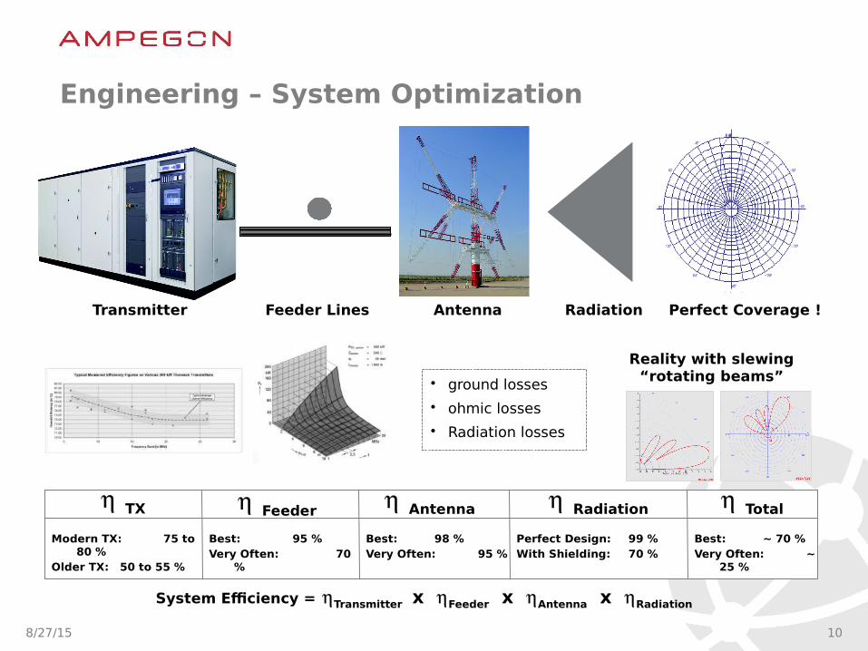
Engineering – System Optimization
TX Feeder Antenna Radiation
System Efficiency = Transmitter x Feeder x Antenna x Radiation
Total
Modern TX: 75 to 80 %
Older TX: 50 to 55 %
Best: 95 %Very Often: 70
%
Best: 98 %Very Often: 95 %
Perfect Design: 99 %With Shielding: 70 %
Best: ~ 70 %Very Often: ~
25 %
Transmitter Feeder Lines Antenna
Reality with slewing “rotating beams”
Radiation Perfect Coverage !
• ground losses
• ohmic losses
• Radiation losses
8/27/15 11
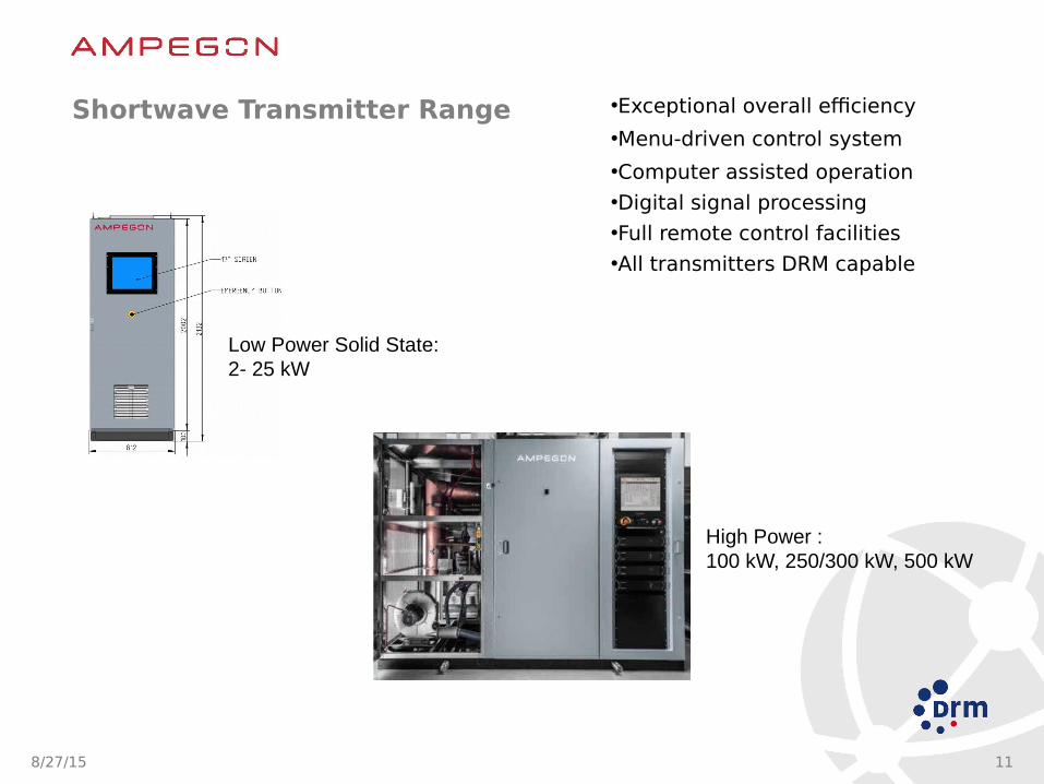
Shortwave Transmitter Range •Exceptional overall efficiency
•Menu-driven control system
•Computer assisted operation
•Digital signal processing
•Full remote control facilities
•All transmitters DRM capable
High Power :100 kW, 250/300 kW, 500 kW
Low Power Solid State:2- 25 kW
8/27/15 12
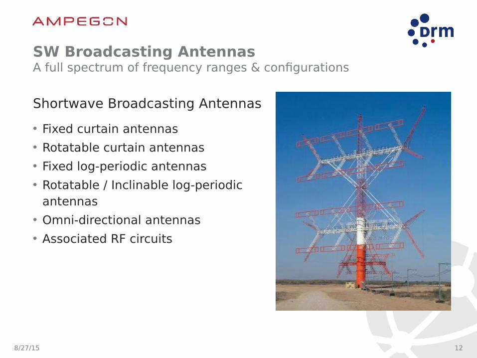
SW Broadcasting AntennasA full spectrum of frequency ranges & configurations
Shortwave Broadcasting Antennas
• Fixed curtain antennas
• Rotatable curtain antennas
• Fixed log-periodic antennas
• Rotatable / Inclinable log-periodic antennas
• Omni-directional antennas
• Associated RF circuits

8/27/15 13
Station Control System: Master Series IIOffering solutions tailored to meet any automation needs
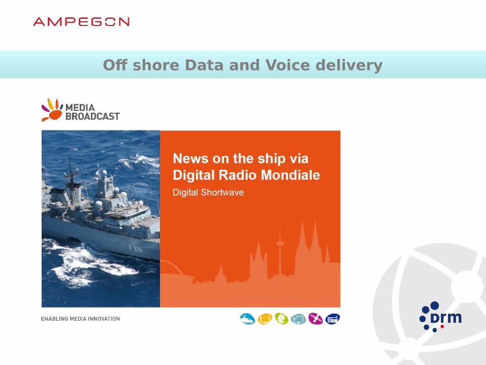
Off shore Data and Voice deliveryOff shore Data and Voice delivery

NAVY and Off shore broadcastNAVY and Off shore broadcast
• Current Situation Poor information available at sea (to late, to slow, too expensive)
• The Solution DRM wide coverage and digital transmission• The Advantage High Quality and cost efficient and live
broadcast• The Service High level service and encryption also possible
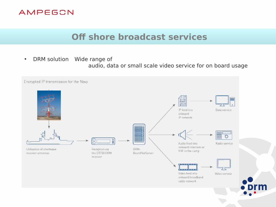
Off shore broadcast services Off shore broadcast services
• DRM solution Wide range of audio, data or small scale video service for on board usage
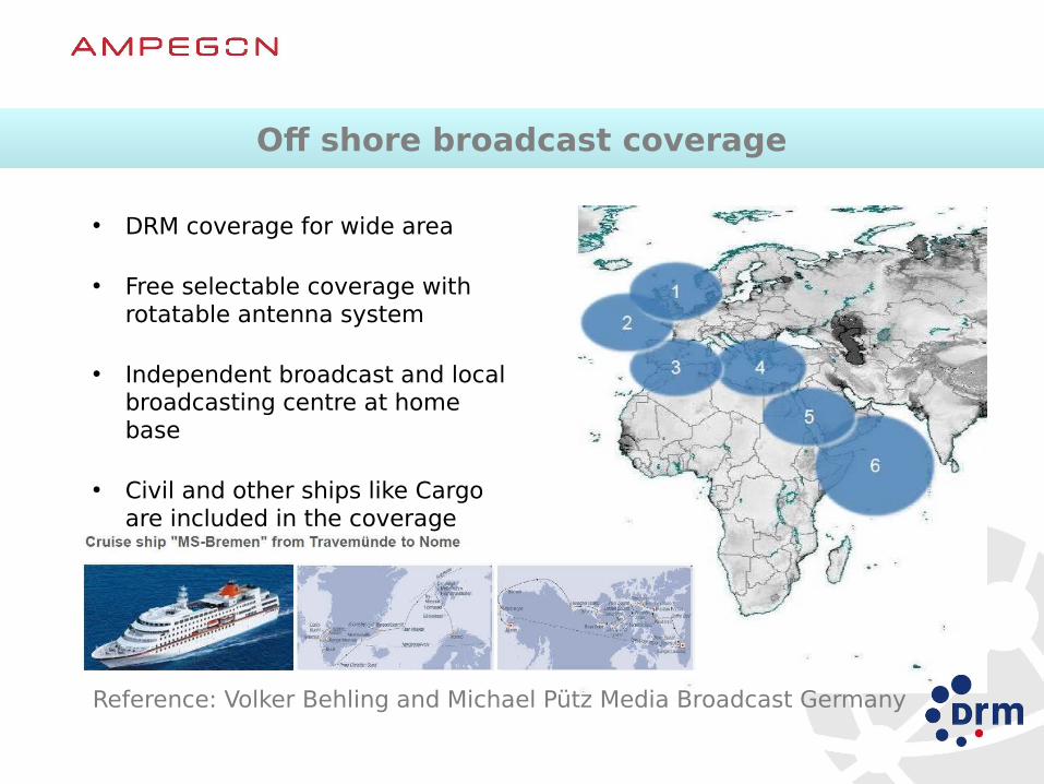
Off shore broadcast coverageOff shore broadcast coverage
• DRM coverage for wide area
• Free selectable coverage with rotatable antenna system
• Independent broadcast and local broadcasting centre at home base
• Civil and other ships like Cargo are included in the coverage
Reference: Volker Behling and Michael Pütz Media Broadcast Germany

MPEG xHE-AAC – Extended HE-AACMPEG xHE-AAC – Extended HE-AAC
AAC-LC
– Equally suits speech and music coding at very low bit rates
– MPEG/ISO standardised in 2012
– Applications:Media download (mobile devices), Streaming, Digital Radio, Mobile TV

• More choice for listeners– Up to 4 programmes on 1 frequency– Simulcast analog / digital
• Excellent audio quality– No distortion– Stereo and 5.1 surround sound
• Multimedia Applications– Great listener benefits– Extra revenue opportunities for broadcasters
• Good coverage area and robust signal– Supporting SFN (Single Frequency Networks)– Green and energy efficient
• Automatic tuning– by station name, no longer by frequency– re-tunes when leaving coverage area
• Emergency warning & alert – All stations switch, present audio and text information
DRM Key FeaturesDRM Key Features
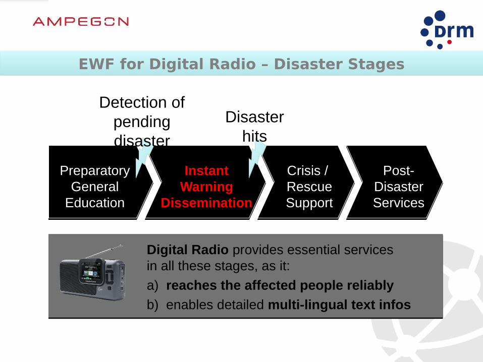
PreparatoryGeneral
Education
InstantWarning
Dissemination
Crisis / RescueSupport
Post-DisasterServices
Detection ofpendingdisaster
Disasterhits
Digital Radio provides essential servicesin all these stages, as it:
a) reaches the affected people reliably
b) enables detailed multi-lingual text infos
EWF for Digital Radio – Disaster StagesEWF for Digital Radio – Disaster Stages
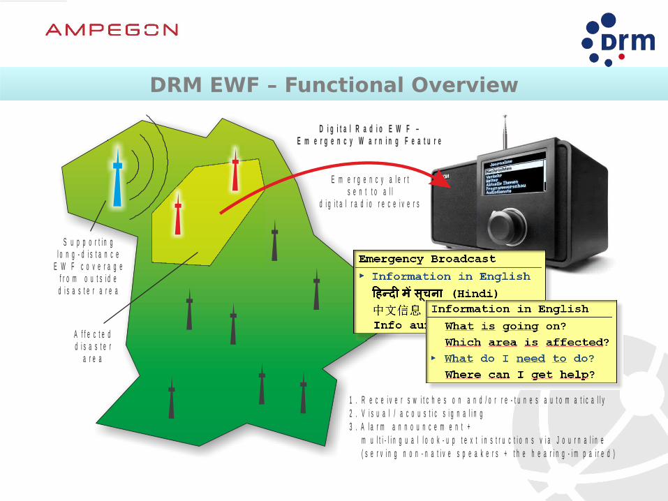
DRM EWF – Functional OverviewDRM EWF – Functional Overview
A f f e c t e dd i s a s t e r
a r e a
E m e r g e n c y a l e r ts e n t t o a l l
d i g i t a l r a d i o r e c e i v e r s
1 . R e c e i v e r s w i t c h e s o n a n d / o r r e - t u n e s a u t o m a t i c a l l y2 . V i s u a l / a c o u s t i c s i g n a l i n g3 . A l a r m a n n o u n c e m e n t + m u l t i - l i n g u a l l o o k - u p t e x t i n s t r u c t i o n s v i a J o u r n a l i n e ( s e r v i n g n o n - n a t i v e s p e a k e r s + t h e h e a r i n g - i m p a i r e d )
D i g i t a l R a d i o E W F –E m e r g e n c y W a r n i n g F e a t u r e
S u p p o r t i n gl o n g - d i s t a n c e
E W F c o v e r a g ef r o m o u t s i d e
d i s a s t e r a r e a

8/27/15 22
Radio New Zealand International
Operating in DRM since 2006 for aprox 19 hrs each day.
Servicing 10 islands with the Ampegon 100 kW shortwave DRM transmitter installed near Taupo, New Zealand.
Re-broadcast on AM and FM via RNZ’s partners in the Pacific.
Easily received on portable DRM receiver with simple whip or wire antenna.
Example of DRM RebroadcastingExample of DRM Rebroadcasting

PreparatoryGeneral
Education
InstantWarning
Dissemination
Crisis / RescueSupport
Post-DisasterServices
Detection ofpendingdisaster
Disasterhits
Digital Radio provides essential servicesin all these stages, as it:
a) reaches the affected people reliably
b) enables detailed multi-lingual text infos
EWF for Digital Radio – Disaster StagesEWF for Digital Radio – Disaster Stages
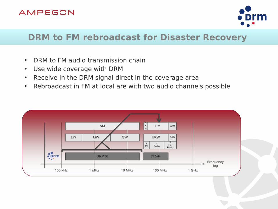
DRM to FM rebroadcast for Disaster Recovery DRM to FM rebroadcast for Disaster Recovery
• DRM to FM audio transmission chain• Use wide coverage with DRM• Receive in the DRM signal direct in the coverage area• Rebroadcast in FM at local are with two audio channels possible
8/27/15 25
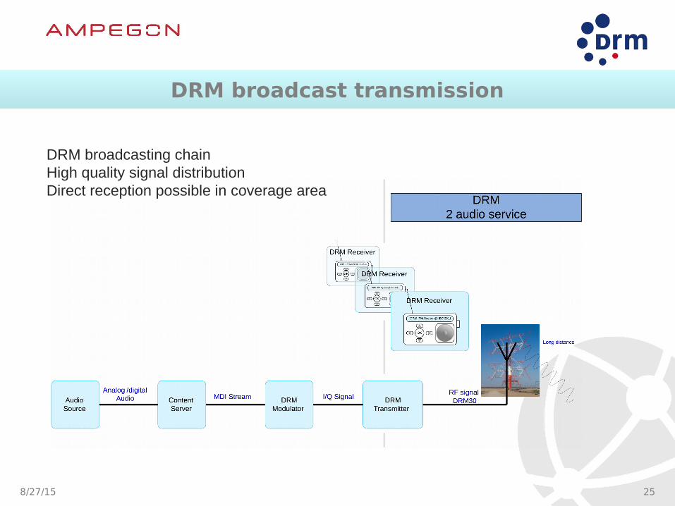
DRM broadcasting chainHigh quality signal distributionDirect reception possible in coverage area
DRM broadcast transmissionDRM broadcast transmission

• Reception and conversion to two FM audio Service
DRM broadcast receptionDRM broadcast reception
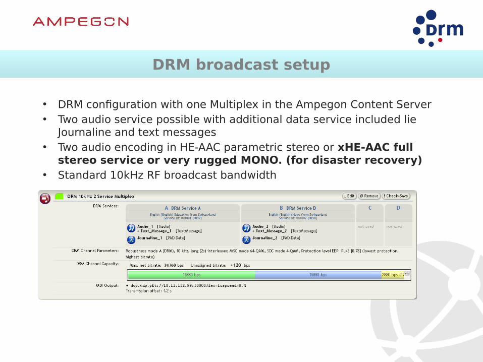
DRM broadcast setupDRM broadcast setup
• DRM configuration with one Multiplex in the Ampegon Content Server• Two audio service possible with additional data service included lie
Journaline and text messages• Two audio encoding in HE-AAC parametric stereo or xHE-AAC full
stereo service or very rugged MONO. (for disaster recovery) • Standard 10kHz RF broadcast bandwidth
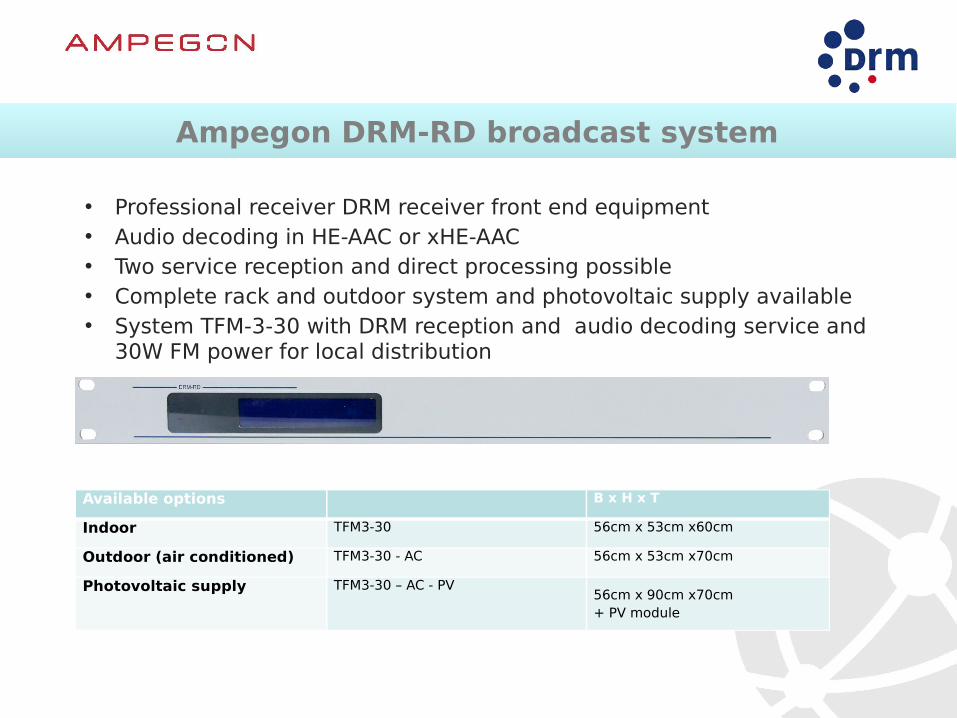
Ampegon DRM-RD broadcast systemAmpegon DRM-RD broadcast system
• Professional receiver DRM receiver front end equipment• Audio decoding in HE-AAC or xHE-AAC • Two service reception and direct processing possible• Complete rack and outdoor system and photovoltaic supply available• System TFM-3-30 with DRM reception and audio decoding service and
30W FM power for local distribution
Available options B x H x T
Indoor TFM3-30 56cm x 53cm x60cm
Outdoor (air conditioned) TFM3-30 - AC 56cm x 53cm x70cm
Photovoltaic supply TFM3-30 – AC - PV56cm x 90cm x70cm+ PV module

8/27/15 30
AM Energy consumption (MW or SW)
• AM Carrier > 66% of energy
• P-USB and P-LSB <33% energy
• AM reception level > 47dByV

8/27/15 31
Analog Energy consumption (MW or SW)
• AM Carrier > 66% of energy (no content)
• P-USB and P-LSB <33% energy (content)
• AM reception level > 47dByV

8/27/15 32
DRM energy consumption -
• Eliminates wasteful AM carrier!
• All energy carries information (content)
• 33% of analogue power. (17% per programme!)with 2 programs via XHE-AAC
• Also DRM reception level > 35dByV(16QAM most robust)or 39dByV (64QAM) according ITU BS1615

8/27/15 33
Coverage – FM vs DRM30
1 DRM transmitter (MW)15 FM transmitter

8/27/15 34
Coverage Example – 10 kW TX’er (5kW DRM power) Short Wave (Myanmar)
Analog
DRM
At Night (9:30 p.m.)
8/27/15 35
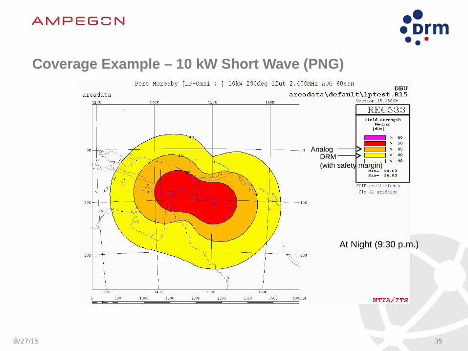
Coverage Example – 10 kW Short Wave (PNG)
AnalogDRM(with safety margin)
At Night (9:30 p.m.)

Tube based shortwave transmitterTube based shortwave transmitter
• Updated tube based High Power TXW-2100TXW-2200 / TXW2300TXW-2500
• New control system platform- embedded DRM modulator- audio signal processing- audio filtering and - modulation mode selection- analogue and digital fast acquisition measurements - fast supervision
• New tuning - drive and motor
positioning system
“old”
“new”
New full solid state Shortwave transmitterNew full solid state Shortwave transmitter
• Broadcast transmitter for shortwave service
• New technology approach
• Step forward in solid state technology
• UCS - Universals Control System platform usage

8/27/15 38
Solid state shortwave transmitterSolid state shortwave transmitter
• New full solid state RF amplifier unit
• Modular concept based on combining of type E-class switch mode RF-amplifier
• Top audio and system performance
• Redundant system approach
• Up to 4 adjusted broadcast band covered
• New low power antenna available to match best system performance and coverage
8/27/15 39
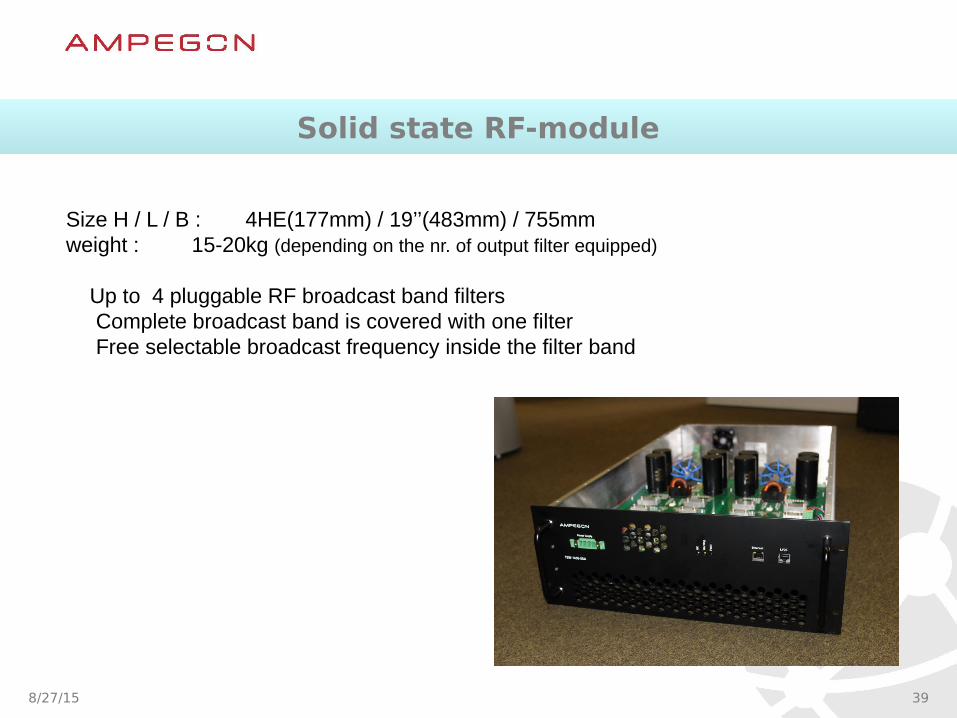
Size H / L / B : 4HE(177mm) / 19’’(483mm) / 755mmweight : 15-20kg (depending on the nr. of output filter equipped)
Up to 4 pluggable RF broadcast band filtersComplete broadcast band is covered with one filterFree selectable broadcast frequency inside the filter band
Solid state RF-moduleSolid state RF-module

Solid state transmitter blockdiagramSolid state transmitter blockdiagram
• Existing UCS from tube based transmitter family, DRM and Remote capability embedded
• New modular type E-class switch mode RF-amplifier
• Wide RF broadcast band coverage with one TX
• Flexible and robust system design
• RF protection included
• Wide range and redundant mains voltage supply available
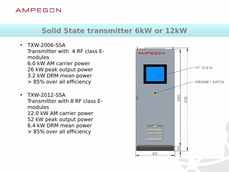
Solid State transmitter 6kW or 12kWSolid State transmitter 6kW or 12kW
• TXW-2006-SSATransmitter with 4 RF class E-modules6.0 kW AM carrier power26 kW peak output power3.2 kW DRM mean power> 85% over all efficiency
• TXW-2012-SSA Transmitter with 8 RF class E-modules12.0 kW AM carrier power52 kW peak output power6.4 kW DRM mean power> 85% over all efficiency
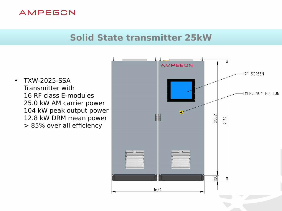
• TXW-2025-SSATransmitter with 16 RF class E-modules25.0 kW AM carrier power104 kW peak output power12.8 kW DRM mean power> 85% over all efficiency
Solid State transmitter 25kWSolid State transmitter 25kW

Solid State transmitter key performanceSolid State transmitter key performance
• Excellent Audio and RF linearity over the broadcast frequency
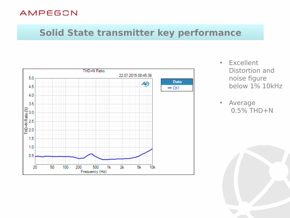
• Excellent Distortion and noise figurebelow 1% 10kHz
• Average 0.5% THD+N
Solid State transmitter key performanceSolid State transmitter key performance

Solid State transmitter key performanceSolid State transmitter key performance
• Excellent RF spectrummeasured at 2.4MHz full power 1.5kW module

8/27/15 46
Brochure
Leaflets
More Information is availableMore Information is available
Homepage

8/27/15 47
Thank you!
Questions?