new jersey department of environmental protection · pdf filenew jersey department of...
TRANSCRIPT

NEW JERSEY DEPARTMENT OF ENVIRONMENTAL PROTECTION
NEW JERSEY ADMINISTRATIVE CODE
TITLE 7, CHAPTER 27B
SUBCHAPTER 3
AIR TEST METHOD 3: SAMPLING AND ANALYTICAL PROCEDURES FOR THE
DETERMINATION OF VOLATILE ORGANIC COMPOUNDS FROM SOURCE
OPERATIONS
FILED:
EFFECTIVE: December 30, 1974
SEE: 7 N.J.R. 48(a)
REVISION EFFECTIVE :
REVISION OPERATIVE: March 28, 1992
SEE: 23 N.J.R. 1858(b), 24 N.J.R. 792(a).
REVISION EFFECTIVE: June 20, 1994
REVISION OPERATIVE: July 26, 1994
SEE: 25 N.J.R. 3339(a), 26 N.J.R. 2600(a).
ADMINISTRATIVE CORRECTION:
SEE: 27 N.J.R. 1406(a)

TABLE OF CONTENTS
SECTION PAGE
7:27B-3.1 Definitions..................................................................................................................4
7:27B-3.2 Sampling and analytical protocol: Acceptable Test Methods......................................10
7:27B-3.3 Operating Conditions During the Test .......................................................................12
7:27B-3.4 Sampling facility to be Provided by the Person Responsible for Emissions..................12
7:27B-3.5 Source Operations and Applicable Test Methods .....................................................13
7:27B-3.6 Procedures for the Determinations of Vapor Pressures of a single known VOC or mixtures
of known and /or unknown VOC .............................................................................14
7:27B-3.7 Procedures for the Direct Measurement of Volatile Organic Compounds Using a Flame
Ionization Detector (FID), a Photoionization Detector (PID) or a Non-Dispersive Infrared
Analyzer (NDIR) .....................................................................................................16
7:27B-3.8 Procedures for the Direct Measurement of Volatile Organic Compounds Using a Gas
Chromatograph (GC) with a Flame Ionization Detector (FID) or other Suitable Detector
................................................................................................................................21
7:27B-3.9 Procedures for the Sampling and Remote Analysis of Known Volatile Organic Compounds
Using a Gas Chromatograph (GC) with a Flame Ionization Detector (FID) or other Suitable
Detector ..................................................................................................................26
7:27B-3.10 Procedures for the Determination of Volatile Organic Compounds in Surface Coating
3
Formulations ............................................................................................................37
7:27B-3.11 Procedures for the Determination of Volatile Organic Compounds Emitted From
Transfer Operations Using a Flame Ionization Detector (FID) or Non-Dispersive
Infrared Analyzer (NDIR) ........................................................................................42
7:27B-3.12 Procedures for the Determination of Volatile Organic Compounds in Cutback and
Emulsified Asphalts ..................................................................................................46
7:27B -3.13 Procedures for the Determination of Leak Tightness of Gasoline Delivery Vessels......48
7:27B- 3.14 Procedures for the Direct Detection of Volatile Organic Compound
Fugitive Leaks..........................................................................................................50
7:27B-3.15 Procedures for the Direct Detection of Volatile Organic Compound
Fugitive Leaks from Gasoline Tank Trucks and Vapor Collection Systems ...............52
7:27B-3.16 Procedures for Determining the Efficiency of Gasoline Vapor Recovery Systems at
Service Stations .......................................................................................................54
7:27B-3.17 Procedures for the Determination of Volatile Organic Compounds Emitted from
Petroleum Solvent Dry Cleaning Operations..............................................................57
7:27B-3.18 Tests Methods and Sources Incorporated by Reference............................................58

4
7:27B-3.1 Definitions
The following words and terms, when used in this subchapter, have the following meanings,unless the context clearly indicates otherwise.
"Aliquot" means a representative portion of a sample.
"ASTM" means the American Society for Testing and Materials.
"Atm" means atmosphere.
"Batch cycle" means the total elapsed time per batch in any single manufacturing process vessel,including all phases of the operation during which the vessel contains process materials, excluding timewaiting for removal from the vessel.
"Calibration gas" means a gas of known composition and concentration, certified to within " twopercent by the manufacturer or, if laboratory blended, an independent analysis has been performed.
"Carrier gas" means nitrogen or helium containing less than two ppm of equivalent carbon ormethane.
"Combustion gas" means air which contains less than two ppm of equivalent carbon or methaneand is used to support the combustion of Volatile Organic Compounds (VOC) in the sample gas.
"Condenser" means a system for determining the moisture content of the source gas andconsisting of: a probe, two Greenburg-Smith impingers (one standard type containing 100 mls ofdistilled water and one dry modified type, both immersed in an ice bath), a drying tube containing asuitable desiccant, a pump, and a dry gas meter with a thermometer all connected in series. Thecondenser collects the moisture in a measured amount of source gas.
"Cutback asphalt" means any paving asphalt which has been liquified by blending withpetroleum solvents, or produced directly from the distillation of petroleum and having vaporizationproperties similar to the blended and liquified asphalt.
"Department" means the New Jersey Department of Environmental Protection.
"Dilution gas" means air or nitrogen containing less than two ppm of equivalent carbon ormethane.

"Direct analysis" means the continuous or semi-continuous on-site sampling and immediateanalysis of the source sample.
"Emulsified asphalt" means asphalt which has been liquified by mixing with water and anemulsifying agent.
"Fuel gas" means hydrogen or a mixture of hydrogen and an inert gas which contains less than oneppm of equivalent carbon or methane.
"Gas chromatograph-flame ionization detector (GC-FID)" means a gas chromatographinstrument equipped with a flame ionization detector and a suitable column to separate the VOC.The flame ionization detector must have a heating system capable of preventing any condensation of thesample gas. The flame ionization detector must be capable of meeting or exceeding by demonstrationthe manufacturer's specifications.
"Gasoline" means any petroleum distillate or petroleum distillate having a Reid vapor pressure offour pounds per square inch (207 millimeters of mercury) or greater and used as an automotive fuel.
"Gas sampling valve" means a two-position heated valve used to purge the sample loop with thesource gas and to insert the loop containing the source gas sample into the carrier gas stream leading tothe chromatograph. Both loop and valve must be heated to a temperature that will prevent anycondensation of the sample gas.
"Isokinetic sampling" means drawing a gas sample through a nozzle into a sampling train at the samevelocity as that in the stack or duct.
"Laboratory standard calibrations gases" means three gas mixtures each containing known concentrations of each of the VOC in the source gas (except trace components) in the same matrix, ifpossible, as will be sampled. One mixture is to have greater than, one mixture is to beapproximately equal to, and one mixture is to have less than the expected concentration of VOC in thesource gas. These gases can be certified to " two percent by the manufacturer or producedlocally by approved techniques if the concentration is confirmed by an independent analysis. Thestandards must be stable in the matrix and container over their period of use.
"LFL" means lower explosive limit.
"Modified particulate train" means a sampling train capable of collecting organic emissions at anisokinetic sampling rate.
"Needle valve" means a fine adjustment valve used to control the source gas sampling rate andconstructed of corrosion-resistant material.

6
"Organic substance" means any chemical compound or mixture of chemical compounds ofcarbon, excluding carbon monoxide, carbon dioxide, carbonic acid, metallic carbonates, metalliccarbides, and ammonium carbonate.
"ppm" means part per million by volume.
"Partial pressure" means the pressure exerted by a specified component in a mixture of gases.
"Performance test" or "test" means a series of test runs used for the purpose of determiningemissions of air contaminants to the outdoor atmosphere.
"Petroleum solvent dry cleaning" means a process used for the cleaning of textiles and fabricproducts in which articles are washed in a solution of organic material produced by petroleumdistillation that exists as a liquid under standard conditions, and then dried by exposure to a heated airstream.
"Probe" means glass, stainless steel or Teflon tubing as required by source gas conditions andequipped with a filter, if necessary. The probe and filter must have a heating or dilution system capableof preventing any condensation of the sample gas.
"Psia" means pounds per square inch absolute.
"Pump" means a leakless Teflon-coated diaphragm pump or equivalent with an appropriatecapacity and a heating or dilution system capable of preventing any condensation of the sample.
"Pure component standards" means a gas mixture consisting of only one VOC in an inert gas. Aseparate mixture is required for each VOC suspected in the source gas.
"Recorder/Integrator" means a strip chart recorder and an optional integrator to calculate theresults.
"Reid vapor pressure" or "RVP" means the absolute vapor pressure of a petroleum product inpounds per square inch (kilopascals) at 100 degrees Fahrenheit (oF) (37.8 degrees Celsius(oC)) as measured by "Method 1-Dry RVP Measurement Method" or "Method 2-Herzog Semi-Automatic Method" promulgated at 40 CFR 80, Appendix E; or any other test method approved inadvance in writing by the Department and the EPA.
"Rigid sampling container" means a leak-free sampling container large enough to hold a gassampling bag and capable of being evacuated to a pressure of 20 inches water without collapsing.

7
"Run" or "test run" means a single integrated measurement or procedure used for the purpose ofcollecting a sample of air contaminants emitted to the outdoor atmosphere during a specified timeinterval.
"Sample collector" means any device used to selectively separate and collect a sample of aspecified contaminant from a gas stream, including, but not limited to, thimbles, filters, impingers,bubblers, cyclones, condensers, and absorbers.
"Sample line" means glass, Teflon or stainless steel tubing with Teflon or stainless steel fittings,heated if necessary to prevent condensation.
"Sampling location" means the specific position at which a sampling port is located in a stack orchimney.
"Sampling port" means an opening in a stack or chimney into which sampling or measuringdevices may be inserted or through which a sample is extracted.
"Sampling rate" means the volume rate at which stack gases are drawn through a sampling train.
"Sampling train" means a combination of entrapment devices, instruments, and auxiliaryapparatus arranged in a prescribed sequence to selectively separate and collect samples of specified aircontaminants.
"SCFH" means standard cubic feet per hour on a wet basis unless otherwise specified in the text.
"SCFM" means standard cubic feet per minute on a wet basis unless otherwise specified in the text.
"Solvent recovery dryer" means a class of dry cleaning dryers that employs a condenser to liquifyand recover solvent vapors evaporated in a closed-loop, recirculating stream of heated air.
"Source operation" or "Source" means any process or any identifiable part of a process, emitting anair contaminant into the outdoor atmosphere through one or more stacks or chimneys..
"Standard conditions" means 70 degrees Fahrenheit (o F) (21.1 degrees Celsius (o C)) and oneatmosphere pressure (14.7 pounds per square inch absolute, 760 millimeters of mercury or 29.92inches Mercury).
"Std" means standard.
"Surface coating formulation" means the material used including, but not limited to paint, varnish, ink,and adhesive, applied a solid surface in order to achieve a finished coating.
8
"Temperature sensor" means a thermometer, potentiometer with thermocouple, or othertemperature sensing device calibrated with an approved standard.
"Test" or "performance test" means a series of test runs used for the purpose of determiningemissions of air contaminants to the outdoor atmosphere.
"Test Run" or "run" means a single integrated measurement or procedure used for the purpose ofcollecting a sample of air contaminants emitted to the outdoor atmosphere during a specified timeinterval.
"Transfer operation" means the moving of any substance from any storage tank, manufacturingprocess vessel, or delivery vessel into any receiving vessel.
"Vapor" means the gaseous form of substances which, under standard conditions, are in the solidor liquid state and which can be changed to these states by either increasing the pressure ordecreasing the temperature.
"Vapor pressure" means the pressure of the vapor phase of a substance, or the sum of the partial pressures of the vapor phases of individual substances in a mixture of substances, when inequilibrium with the non-vapor phase of the substance or substances.
"Velocity Meter" means an "S" type Pitot tube with a manometer or other appropriate gas flowmeasuring device.
"Volatile organic compounds" or "VOC" means any compound of carbon (other than carbonmonoxide, carbon dioxide, carbonic acid, metallic carbonates, metallic carbides, and ammoniumcarbonate) which participates in atmospheric photochemical reactions. For the purpose ofdetermining compliance with emission limits or content standards, VOC shall be measured bytest methods in the approved SIP (such as N.J.A.C. 7:27B-3) or 40 CFR Part 60, Appendix A, asapplicable, or which have been approved in writing by the Department and are acceptable toEPA. This term does not include the compounds which EPA has excluded from its definition ofVOC in the list set forth at 40 CFR 51.100(s)(1), which is incorporated by reference herein, togetherwith all amendments and supplements. The list at 40 CFR 51.100(s)(1) currently includes thecompounds and the classes of perfluorocarbons set forth below:
methane
ethane
methylene chloride (dichloromethane)

9
1,1,1-trichloroethane (methyl chloroform)
trichlorofluoromethane (CFC-11)
dichlorodifluoromethane (CFC-12)
trifluoromethane (HFC-23)
1,1,2-trichloro-1,2,2-trifluoroethane (CFC-113)
1,2-dichloro-1,1,2,2-tetrafluoroethane (CFC-114)
chloropentafluoroethane (CFC-115)
chlorodifluoromethane (HCFC-22)
2,2-dichloro-1,1,1-trifluoroethane (HCFC-123)
2-chloro-1,1,1,2-tetrafluoroethane (HCFC-124)
1,1-dichloro-1-fluoroethane (HCFC-141b)
1-chloro-1,1-difluoroethane (HCFC-142b)
pentafluoroethane (HFC-125)
1,1,2,2-tetrafluoroethane (HFC-134)
1,1,1,2-tetrafluoroethane (HFC-134a)
1,1,1-trifluoroethane (HFC-143a)
1,1-difluoroethane (HFC-152a)
parachlorobenzotrifluoride (PCBTF)
cyclic, branched or linear completely methylated siloxanes
Classes of perfluorocarbons:

10
cyclic, branched, or linear, completely fluorinated alkanes
cyclic, branched, or linear, completely fluorinated ethers with no unsaturations
cyclic, branched, or linear, completely fluorinated tertiary amines with no unsaturationssulfur containing perfluorocarbons with no unsaturations and with sulfur bonds only to carbonand fluorine
If there is any conflict between the list at 40 CFR 51.100(s)(1) and the list set forth above, the listat 40 CFR 51.100(s)(1) shall control.
"Zero gas" means air or gas which contains less than 1 ppm of equivalent carbon or methane.
7:27B-3.2 Sampling and Analytical protocol: acceptable test methods
(a) When N.J.A.C. 7:27-8, 7:27-16, 7:27-17, or 7:27-23 requires a source emissions test, theapplicant shall submit a written protocol to the Department at least 30 days prior to the date of the test,to the following address:
Chief, Bureau of Technical Services
Division of Environmental [Quality] Regulation
Department of Environmental Protection
[CN] P.O. Box [411] 437
380 Scotch Road
Trenton, New Jersey [08625-0411] 08625-0437
(b) The written protocol shall include a detailed description of the following:
1. Sampling location;
2. Sampling equipment;
3. Sampling and analytical procedures for the tests;

11
4. Data reporting forms; and
5. Quality assurance procedures.
(c) Any alternative test method, analytical method, instrumentation, source, test period, or datareporting forms shall be submitted in writing with the test protocol for approval at the discretion of theDepartment at least 30 days prior to the test, to the address set forth in (a) above.
(d) Any changes from the procedures and methods set forth in the protocol may be approvedverbally prior to the test at the discretion of the Department; however, the applicant shall note therequest and the Department's response in the final test report submitted by the applicant to theDepartment.
(e) Any Departmental approval pursuant to (c) or (d) above shall be confirmed in writing by theDepartment.
(f) The Department may itself employ such alternative procedures when warranted by testconditions or other circumstances.
(g) The applicant shall give notice to the Department at least 48 hours prior to the test in order toafford the opportunity for a Departmental observer(s) to be present.
(h) Performance tests shall be conducted in accordance with test methods set forth hereinafter.
(i) For determining the quality and quantity of VOC from source operations, the prescribed testprocedures shall be as follows:
1. For a single known VOC: Procedures for the Direct Measurement of VOC Using aFlame Ionization Detector or a Photoionization Detector or a Non-Dispersive Infrared Analyzer (N.J.A.C. 7:27B-3.7).
2. For a mixture of known VOC in known proportion: Procedures for the DirectMeasurement of VOC Using a Flame Ionization Detector, a Photoionization Detector or aNon-Dispersive Infrared Analyzer (> N.J.A.C. 7:27B-3.7).
3. For a mixture of known VOC in unknown proportions: Procedures for the DirectMeasurement of VOC Using a Gas Chromatograph with a Flame Ionization Detector or other suitabledetector (N.J.A.C. 7:27B-3.8).
4. For a mixture containing unknown VOC: A procedure has not been included in the
12
test methods, but an analysis using a gas chromatograph with a mass spectrometer will be required andconducted in accordance with established procedures by a qualified operator. Prior to any such test,the Department must receive and approve a written protocol from the operator.
5. For a known or unknown VOC in a stack where condensation is present, isokineticsampling will be required. A procedure has not been included in these test methods, but sampling usingan approved modified particulate train will be required, which shall be submitted for Departmentalreview pursuant to N.J.A.C. 7:27B-3.2(c), (d), and (e).
(j) Whenever a direct analysis at the source is not possible, the samples shall be taken inaccordance with the procedure described at N.J.A.C. 7:27B-3.9.
(k) Whenever a volume flow rate must be determined to establish mass emission rates of VOC orfor any other reason, the methods prescribed in N.J.A.C. 7:27B-1, AIR TEST METHOD 1 ( N.J.A.C.7:27B-3.18 Reference 1), or other flow determining method which shall be submitted for Departmentalreview pursuant to N.J.A.C. 7:27B-3.2(c), (d), and (e).
7:27B-3.3 Operating conditions during the test
Insofar as practical, the source operation will be tested while operating at normal routine conditionsand, as necessary, at other conditions including, but not limited to, design, maximum and fluctuatingrates.
7:27B-3.4 Sampling facilities
(a) The following sampling facilities shall be provided by the party responsible for the emissions:
1. Sampling ports installed at locations specified by the Department and of a size largeenough to accommodate the sampling equipment;
2. Safe sampling platforms and safe access thereto conforming with laws and regulationsconcerning safe construction and safe practice (N.J.A.C. 7:27B-3.18, Reference 2);
3. Utilities as needed for sampling and testing equipment, which may include electricalpower and water;
4. Any other facilities exclusive of instrumentation and sensing devices as may benecessary for the Department to accurately determine the emissions of VOC from the source operation;
5. Facilities, as necessary, for representative sampling of raw materials and for the

13
determination of the amount of raw materials being used during the test run; and
6. The facilities installed may be either permanent or temporary, at the discretion of theparty responsible for their provision.
7:27B-3.5 Source operations and applicable test methods
The following chart sets forth the applicable test methods, shown by section designation, for thevarious source operations that are regulated by N.J.A.C. 7:27-8, 7:27-16, 7:27-17, and 7:27-23:
Applicable Test Methods
Source Operation VaporPressure
Efficiency ofControlApparatus
LeaksFromSource
EmissionsFrom Source
VOCContent
Leak Tightness ofDelivery Vessel
RecoveredSolvent FlowRate
Storage of VOC 3.6 3.7 3.14
3.8
3.9
Transfer Operations 3.6 3.16 3.15 3.11 3.13
Open Top Tanks andSurface Cleaners
3.6 3.7 3.7 3.10
3.8 3.8
3.9 3.9
Surface Coating Operations
3.7 3.7
3.8 3.8
3.9 3.9
Source Operations Other Than Storage Tanks, Open Top Tanks, and SurfaceOuters
3.6 3.73.83.9
3.14 3.73.83.9
Cutback and EmulsifiedAsphalt
Petroleum Solvent DryCleaners
3.17
14
7:27B-3.6 Procedures for the determinations of vapor pressures of a single known VOC or mixturesof known and/or unknown VOC
(a) The vapor pressure of a single known volatile organic substance shall be determined as follows:1. The vapor pressure of certain single known VOC may be found in the following, or other
sources which shall be submitted to the Department for review, pursuant to N.J.A.C. 7:27B-3.2(c), (d), and(e), and may be used provided the vapor pressure was measured and the VOC was certified by themanufacturer or by the National Bureau of Standards as being of or equivalent to research grade.
i. Weast, R.C., "Handbook of Chemistry and Physics," Section D, Chemical Rubber Co.,Cleveland, Ohio;
ii. Perry, J.H., "Chemical Engineers" Handbook, Section 3, McGraw-Hill, New York;
iii. Lange, N.A., "Handbook of Chemistry," McGraw-Hill, New York;
iv. Boublik, T.; Grued, V.; and Hala, E., "The Vapor Pressure of Pure Substances,"Elsevier Scientific Publishing, New York;
v. Jordan, T.E., "Vapor Pressure of Organic Compounds" Interscience Publishers, New York.
2. In the absence of the referenced data above, the vapor pressure of the single VOC may bedetermined by the following methods:
i. "Method 1-Dry RVP Measurement Method" or "Method 2-Herzog Semi-AutomaticMethod" promulgated at 40 CFR 80, Appendix E; or any other test Method approved in advance in writing bythe Department and the EPA, ( N.J.A.C. 7:27B-3.18, Reference 3). This method may be used only if thesensitivity of the pressure measuring device is sufficient for the vapor pressure level. The results must beconverted to and reported as the true vapor pressure at standard conditions ( N.J.A.C. 7:27B-3.18, Reference5); or
ii. ASTM Designation D2879-75, "Standard Method of Test for VaporPressure--Temperature Relationship and Initial Decomposition Temperature of Liquids by Isoteniscope" (N.J.A.C. 7:27B-3.18, Reference 4).
(b) The vapor pressures of mixtures of known VOC in known proportions shall be determined as follows:
1. Data on partial pressure for certain mixtures of VOC are published in the International Critical

15
Tables and in scientific journals. The vapor pressure of a mixture which has been reported in such sources willbe acceptable provided the source is documented by a reprint which shall be submitted for review by theDepartment, pursuant to N.J.A.C. 7:27B-3.2(c), (d) and (e).
2. The vapor pressure may also be determined by the method set forth in (a)2i above. The Reid method isapplicable to volatile crude oil and volatile nonviscous petroleum products and other mixtures of VOC. Forpetroleum and petroleum distillates, refer to American Petroleum Institute (API) Bulletin 2517, "Selecting theProper Nomograph" ( N.J.A.C. 7:27B-3.18, Reference 5). The Reid vapor pressure can be converted to truevapor pressure at standard conditions. For mixtures other than petroleum and petroleum distillates, the resultingReid vapor pressure may be converted to true vapor pressure at standard conditions using Table 1.
TABLE 1
CONVERSION OF REID VAPOR PRESSURES TO TRUE VAPOR PRESSURES
Reid Vapor Pressure True Vapor Pressure
Psia Psia
1 0.5
2 1.1
3 1.7
4 2.3
5 2.9
6 3.6
7 4.2
8 4.8
9 5.5
10 6.1
11 6.7
12 7.4
13 8.0
14 8.6

16
14.7 9.0
3. The method set forth in (a)2ii above.7:27B-3.7 Procedures for the direct measurement of volatile organic compounds using a flameionization detector (FID), a photoionization detector (PID) or a non-dispersive infrared analyzer(NDIR)
(a) The method in this section is applicable for the determination of the concentration and the mass emissionrate of a known VOC or a mixture of known VOC in known proportions in systems with constant emissionsand flow rates. For the same circumstances as described above, the procedures specified in N.J.A.C.7:27B-3.8 or 3.9 may be used in place of this method. Any other alternative test method shall be submitted tothe Department for review, pursuant to N.J.A.C. 7:27B-3.2(c), (d) and (e).
(b) This method is based upon the following principles:
1. The flame ionization method is based upon ionization produced when the organic vapor in thesample is combusted in a hydrogen flame. The ions and electrons formed in the flame enter an electrode gap,decrease the gap resistance, and thus permit a current flow in an external circuit. The resulting current isproportional to the instantaneous concentration of the organic vapor.
2. The photoionization method is based upon ionization produced when an organic vapor in thesample is exposed to a high intensity ultraviolet source. The ions and electrons formed enter an electrode gap,decrease the gap resistance, and thus permit a current flow in an external circuit. The resulting current isproportional to the instantaneous concentration of the organic vapor.
3. The non-dispersive infrared method is based upon absorption of infrared energy when a bandof infrared energy containing the proper frequencies is alternately passed through an absorption cell containingthe organic vapor and a reference cell. The difference in absorption between the reference cell and theabsorption cell containing the organic vapor is proportional to the instantaneous concentration of the organicvapor.
(c) The following is a summary of this method:
1. The instrument is calibrated with standard gas mixtures to establish the instrument response tothe VOC being analyzed. A representative sample of the source gas is drawn into the instrument underconditions which prevent any condensation of the source gas and which remove particulate matter. Theresponse is recorded at specified intervals during the test period, and the true concentration of the VOC iscalculated from previously determined response factors. The total gas flow rate, moisture content, and theaverage molecular weight of the gas are determined during the sampling period, and the mass emission rate ofthe VOC is calculated and reported as pounds per hour.

17
2. For the purposes of this procedure, three separate test runs will be conducted, each of whichshall extend for one hour or a batch cycle whichever is longer. Any alternative test period shall be submitted tothe Department for review, pursuant to > N.J.A.C. 7:27B-3.2(c), (d) and (e).
(d) The following is a list of equipment used in this method:
1. Probe;
2. Sample line;
3. Temperature sensor;
4. Pump;
5. Detector: a total hydrocarbon analysis instrument having a flame ionization, a photoionizationor a non-dispersive infrared detector and a sampling system capable of preventing any condensation of thesample gas. The detector must be capable of meeting or exceeding the manufacturer's specifications bydemonstration, preferably by the manufacturer, and the other specifications listed below:
i. Linearity: the instrument response to the VOC being measured shall not deviate fromlinearity by more than five percent of the full scale value of the range being used.
ii. Zero drift: less than three percent of full scale per test period or one hour, whichever isshorter.
iii. Span drift: less than three percent of full scale per test period or one hour whichever isshorter.
iv. Response time: equal to or less than 30 seconds for 95 percent full scale.
6. Recorder/Integrator:
7. Gas cylinder supplies as follows:
i. Laboratory standard calibration gases;
ii. Field standard: a known concentration of methane used to check instrument response inthe field;
iii. Fuel gas;
18
iv. Combustion gas; and
v. Zero gas;
8. Velocity meter;
9. Condensor; and
10. Dilution system (if necessary): a system supplied by the instrument manufacturer or one similar tothat specified in N.J.A.C. 7:27B-3.9(e) 4, capable of producing dilution ratios which will prevent anycondensation of the sample gas and capable of bringing the sample concentration within the linear range ofthe detector.
(e) The procedure for this section shall be as follows:
1. A presampling survey of the source operation shall be conducted to establish certain basicinformation including but not limited to: sampling location; stack temperature and pressure; stack gasmoisture content; approximate particulate concentrations; composition of the gases; and the identificationand approximate concentrations of the VOC to be analyzed. It may be necessary to take samples foranalysis to acquire any information that is not readily available.
2. The instrument shall be calibrated as follows:
i. The instrument shall be operated according to the manufacturer's instructions;
ii. Adjust the analyzer to the zero reading by using zero gas; and
iii. Introduce three laboratory standard calibration gases separately recording the response foreach. Plot the response versus the concentration. No response should deviate from the best fit line through thethree points by more than five percent. If linearity cannot be obtained over the concentration range expected,the sample should be diluted to a concentration level where linearity can be obtained.
iv. Introduce a sample of the field standard and record the response.
3. The sampling and analysis shall be conducted as follows:
i. Assemble and connect any sampling probe, filter, and heating or dilution system to the instrument. All connections shall be tight and leak-free;
ii. Adjust the heating or dilution system to prevent any condensation of the sample gas;
19
iii. Analyze a sample of the field standard and adjust the instrument to the reading determinedduring calibration. If a dilution system must be used, record the response of the field standard with the dilutionsystem in place and determine a new calibration curve at the same conditions used in the field;
iv. The probe should be positioned at least two feet into the stack or at the centroid of the stack. Thesample port location should be in accordance with N.J.A.C. 7:27B-1, Air Test Method 1, ( N.J.A.C.7:27B-3.18, Reference 1);
v. Activate the system and adjust as necessary to achieve the manufacturer's recommendedoperating conditions. Record the instrument response using a continuous recording device if available; if acontinuous reading device is not available, take a reading at intervals of no less than one minute. Note anynon-representative operations or occurrences during the testing and omit those corresponding analyzer readingsfrom the calculations;
vi. For the purposes of this procedure, three separate and valid test runs will be conducted, eachof which shall extend for one hour or a batch cycle whichever is longer. Any alternative test period shall besubmitted to the Department for review pursuant to N.J.A.C. 7:27B-3.2(c), (d) and (e);
vii. During the test period, determine the stack gas velocity, temperature, moisture content,average gas molecular weight, and volumetric flow rates in accordance with the methods prescribed in N.J.A.C.7:27B-1 AIR TEST METHOD 1 (N.J.A.C. 7:27B-3.18, Reference 1) or other flow determining method whichshall be submitted to the Department for review, pursuant to > N.J.A.C. 7:27B-3.2(c), (d) and (e). SeeAppendix A for the required reporting form. (Any alternative reporting form shall be submitted to theDepartment for review pursuant to N.J.A.C. 7:27B-3.2(c) and (e).)
viii. At the conclusion of each test run, note the time and introduce the field standard gas anddetermine and record its response. The net response must agree within five percent of the pretest response forthe test to be valid.
(f) The calculations shall be performed as follows:
1. Establish the molecular weight of each VOC and calculate a weighted average molecular weight if morethan one VOC is present.
2. Calculate the total gas flow rate from the source in SCFM (70° F and 1 atm) including the contribution ofthe VOC and any moisture present.
3. Determine the response factor (RF) of the lab standard from the following equation.
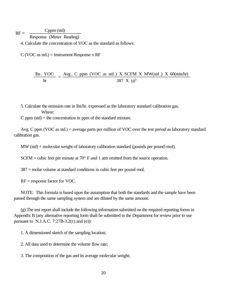
20
Reading)(Meter Response(std) Cppm
=RF
4. Calculate the concentration of VOC as the standard as follows:
C (VOC as std.) = Instrument Response x RF
5. Calculate the emission rate in lbs/hr. expressed as the laboratory standard calibration gas. Where:
C ppm (std) = the concentration in ppm of the standard mixture.
Avg. C ppm (VOC as std.) = average parts per million of VOC over the test period as laboratory standardcalibration gas.
MW (std) = molecular weight of laboratory calibration standard (pounds per pound-mol).
SCFM = cubic feet per minute at 70° F and 1 atm emitted from the source operation.
387 = molar volume at standard conditions in cubic feet per pound-mol.
RF = response factor for VOC.
NOTE: This formula is based upon the assumption that both the standards and the sample have beenpassed through the same sampling system and are diluted by the same amount.
(g) The test report shall include the following information submitted on the required reporting forms inAppendix B (any alternative reporting form shall be submitted to the Department for review prior to usepursuant to N.J.A.C. 7:27B-3.2(c) and (e)):
1. A dimensioned sketch of the sampling location;
2. All data used to determine the volume flow rate;
3. The composition of the gas and its average molecular weight;
10 X 38760(min/hr) X .)MW(std X SCFM X .)std as (VOC ppm C .Avg
= hr
VOC .lbs 6

21
4. A sketch and/or description of the sampling system used;
5. The identity, concentration and means of verification for each standard used;
6. A description of the analysis instrument and the conditions of operation;
7. Sufficient details of the calculations to allow the results to be reproduced independently;
8. The emission rate measured in lbs/hr of each VOC for each test;
9. Operating conditions of the source operation; and
10. An explanation for any unusual procedures or results.
7:27B-3.8 Procedures for the direct measurement of volatile organic compounds using a gaschromatograph (GC) with a flame ionization detector (FID) or other suitable detector
(a) The method in this section is applicable for the determination of the concentrations and the massemission rates of any known VOC in unknown proportions in systems with constant emissions and flow rates. For the same circumstances as described above, the procedure specified in N.J.A.C. 7:27B-3.9 may be used inplace of this method. Any other alternative test method shall be submitted to the Department for reviewpursuant to N.J.A.C. 7:27B-3.2(c), (d) and (e).
(b) This method is based upon the following principles:
1. Gas chromatography, whereby VOC are separated by passing an inert gas stream containing a knownvolume of the sample gas or a standard gas through a column containing a suitable stationary phase and/or asolid support; and
2. Ionization produced when each VOC in the gas sample as eluted from the gas chromatograph iscombusted in a hydrogen flame. The ions and electrons formed in the flame enter an electrode gap, decreasethe gas resistance, and thus permit a current flow in an external circuit. The resulting current is proportional tothe instantaneous concentration of the VOC. Any alternative detector shall be submitted to the Department forreview pursuant to N.J.A.C. 7:27B-3.2(c), (d) and (e).
(c) The following is a summary of this method:
1. The GC-FID is calibrated with standard gas mixtures containing each VOC being measured to establishthe calibration curves and retention times. A representative sample is drawn into the gas sampling loop underconditions which prevent any condensation of the sample gas and which remove particulate matter. The sampleis injected into the GC, the responses and retention times of the individual VOC are recorded on a strip chart

22
recorder, and the peak areas of each VOC are measured. The peaks are identified from the establishedretention times. The concentration of each VOC is determined by referring to the calibration curve. The totalgas flow rate, moisture content, and the average molecular weight of the gas are determined during the samplingperiod, and the mass emission rate of the VOC is calculated and reported as pounds per hour.
2. For the purposes of this procedure, three separate test runs will be conducted, each of which shallextend for one hour or a batch cycle whichever is longer. Any alternative test period shall be submitted to theDepartment for review pursuant to N.J.A.C. 7:27B-3.2(c), (d) and (e).
3. In situations where safety considerations, location, or number of sample points prohibit direct analysis atthe VOC source, the samples are collected in accordance with the method prescribed in N.J.A.C. 7:27B-3.9and transported to the GC-FID for analysis.
(d) The following is a list of equipment used in this method:
1. Probe;
2. Sample line;
3. Temperature sensor;
4. Pump;
5. Gas sampling valve;
6. Needle valve;
7. Gas chromatograph-flame ionization detector (GC-FID);
8. Recorder/Integrator;
9. Gas cylinder supplies as follows:i. Laboratory standard calibration gases;
ii. Pure components standard;
iii. Fuel gas;
iv. Combustion gas; and
v. Carrier gas.

23
10. Velocity meter;
11. Condensor; and
12. Dilution system (if necessary): a system as described in N.J.A.C. 7:27B-3.9.(e)4, capable ofproducing dilution ratios which will prevent any condensation of the sample gas and capable of bringing thesample concentration within the linear range of the GC detector.
(e) The procedure for this section shall be as follows:
1. A presampling survey of the source operation(s) shall be conducted to establish certain basicinformation including but not limited to: sampling location; stack temperature and pressure; stack gas moisturecontent; approximate particulate concentration; composition of the gases; and the identification andapproximate concentrations of the VOC to be analyzed. It may be necessary to take samples for analysis toacquire any information that is not readily available.
2. The instruction shall be calibrated as follows:
i. The instruction shall be operated according to the manufacturer's instructions;ii. The operating parameters of the instruction such as column selections, temperatures, carrier gas flow
rate, and chart speed shall be established for the VOC to be measured and verified in the laboratory prior toactual sampling. The conditions selected should produce baseline separation of the individual VOC peaks, ifpossible, but in no case should the height of the valley between the two peaks measured from the baseline to thelowest point in the valley be greater than 30 percent of the height of the shorter of the two peaks. More thanone set of conditions may be necessary for complete resolution;
iii. The instrument operating conditions shall be recorded on the chart and maintained throughout thecalibration and sample gas analyses. The operating conditions to be recorded are sample loop temperature,column temperature, carrier gas flow rate, and chart speed. Attenuator setting shall be adjusted as required andrecorded on the chart to indicate the time and amount of adjustment;
iv. Purge the sample loop with one of the calibration gas mixtures and record the concentration;
v. Activate the sampling valve to inject the sample and mark the injection point on the chart;
vi. Measure the distance on the chart from the injection point to the time at which the peak maximumoccurs for the calibration mixture. This distance divided by the chart speed will provide the retention time foreach compound;

24
vii. Calculate the sample peak areas by multiplying the height times the width at half height and adjusteach peak area by the attenuator setting as required. An integrator may be used to calculate peak areas;
viii. Repeat steps iv through vii for each calibration gas until two consecutive analyses agree within fivepercent. The corresponding peak areas for each VOC shall then be averaged;
ix. Plot the areas of each peak versus the concentration on suitable graph paper. If any point shoulddeviate from a straight line by more than five percent, the calibration shall be repeated. If a straight line is notobtained, less concentrated standards or a smaller sample must be used to bring the response within the linearrange of the detector; and
x. Draw a straight line through the points to establish a calibration curve for each VOC. Calculate theunknown VOC concentrations from their peak areas by reading from the appropriate calibration curve or bymultiplying the peak area by the slope of the calibration curve. Extrapolation beyond the calibrated range is notacceptable.
xi. The instrument calibration shall be checked just prior to each test. The calibration gas shall beintroduced through the sampling system in a manner similar to the introduction of the source gas.
3. The sampling and analysis shall be conducted as follows:
i. Assemble and connect any sampling probe, sample line, filter and heating or dilution system tothe GC-FID. All connections shall be tight.
ii. Turn on the GC and source gas sampling systems and adjust conditions to prevent anycondensation of the sample gas;
iii. If a dilution system is used, run three field standards through the dilution system and theinstrument and record each response. The response shall not deviate from linearity by more than five percent;
iv. The probe shall be positioned at least two feet into the stack or at the centroid of the stack. The sample port location shall be in accordance with N.J.A.C. 7:27B-1, AIR TEST METHOD 1 (N.J.A.C.7:27B-3.18, Reference 1);
v. After thoroughly purging the gas sampling loop with source gas, analyze a sample of thesource gas maintaining the same instrument operating conditions used during the calibration procedures. Calculate the concentrations of the components by referring to the calibration curve; and
vi. Repeat the analysis at uniform intervals as many times as practical during the test run. Noless than three sample analyses per test run shall be acceptable;

25
vii. For the purposes of this procedure three separate and valid test runs will be conducted,each of which shall extend for one hour or a batch cycle whichever is longer. Any alternative test period shallbe submitted to the Department for review pursuant to N.J.A.C. 7:27B-3.2(c), (d) and (e).
viii. During the test period, determine the stack gas velocity, temperature, moisture content,average gas molecular weight, and volumetric flow rates in accordance with the methods prescribed in N.J.A.C.7:27B-1, AIR TEST METHOD 1 (N.J.A.C. 7:27B-3.18, Reference 1), or other flow determining methodsubmitted to the Department for review pursuant to N.J.A.C. 7:27B-3.2(c), (d) and (e). See Appendix A forthe required reporting form. (Any alternative reporting forms shall be submitted to the Department for reviewpursuant to N.J.A.C. 7:27B-3.2(c) and (e).)
ix. At the conclusion of each test run introduce the calibration gas in a manner similar to theintroduction of the source gas and determine the response. The net response must agree to within " fivepercent of the pretest response for the test to be valid.
(f) The calculations shall be performed as follows:
1. Establish the molecular weight of each VOC.
2. Calculate the total gas flow rate from the source operation(s) in SCFM (70o F and 1 atm) includingthe contribution of the VOC and any moisture present.
3. Record the individual concentrations (C ppm) and determine the average concentration (C) of each VOCin ppm (avg. C ppm) for each test run from the calibration curves.
4. Calculate the emission rate in lbs/hr of each VOC as follows:
Where:
Avg. C ppm(VOC) = average parts per million of VOC over the test period.
MW (VOC) = molecular weight of VOC (pounds per pound-mol).
SCFM = cubic feet per minute at 70o F and 1 atm emitted from the source operation.
387 = molar volume at standard conditions in cubic feet per pound-mol.
10 X 387SCFM X (VOC)MW X ppm(VOC) C .Avg
= hr
VOC lbs6

26
NOTE: This formula is based upon the assumption that both the standards and the sample have beenpassed through the same sampling system and diluted by the same amount.
5. Calculate the total emission rate in lbs/hr of the VOC by totaling the individual VOC calculated in (f)4above.
(g) The test report shall include the following information submitted on the required reporting form inAppendix C (any alternative reporting form shall be submitted to the Department for review pursuant toN.J.A.C. 7:27-3.2(c) and (e)):
1. A dimensioned sketch of the sampling location;
2. All data used to determine the volume flow rates;
3. The composition of the gas and its average molecular weight;
4. A sketch and/or description of the sampling system used;
5. The identity, concentration, and means of verification for each standard used;
6. A description of the analysis instrument and the conditions of operation;
7. Copies of the chromatograms for each standard and each test run identified as to time taken andpertinent instrument and dilution conditions;
8. Sufficient details of the calculations to allow the results to be reproduced independently;9. The emission rate measured in lbs/hr of each VOC for each test;
10. Operating conditions of the source operations; and
11. An explanation for any unusual procedures or results.
7:27B-3.9 Procedures for the sampling and remote analysis of known volatile organic compoundsusing a gas chromatograph (GC) with a flame ionization detector (FID) or other suitable detector
(a) The method in this section is applicable for the determination of the concentration and the massemission rates of known VOC from a source where it is not practical to conduct a direct analysis at thesource or in systems where the flow rates are not constant. For the same circumstances as described above,any other alternative test method shall be submitted to the Department for review pursuant to N.J.A.C.7:27B-3.2(c), (d) and (e).

27
(b) This method is based upon the following principles:
1. The reduction of the moisture and VOC levels in the source gas by condensation or dilution;
2. Collecting the resulting dry sample gas in a Tedlar or equivalent bag;
3. Gas chromatography whereby each VOC is separated by passing an inert gas stream containinga known volume of the sample gas or standard gas through a column containing a stationary phase and/or asolid support; and
4. Ionization produced when each VOC in the sample gas as eluted from the gas chromatograph iscombusted in a hydrogen flame. The ions and electrons formed in the flame enter an electrode gap, decreasethe gap resistance, and thus permit a current flow in an external circuit. The resulting current is proportionalto the instantaneous concentration of the VOC. Any alternative detector shall be submitted to theDepartment for review pursuant to N.J.A.C. 7:27B-3.2(c), (d) and (e).
(c) The following is a summary of this method:
1. A representative sample from the source is drawn at a constant rate through a heated sampleline to a series of condensors in an ice bath where the moisture and condensable VOC are removed, or to adilution system which reduces the concentration of the source gas by a known amount with hydrocarbon-freeair. The dry sample gas is collected in a Tedlar or equivalent sampling bag which, along with any collectedcondensate, is transported to the GC-FID for analysis.
2. The GC-FID is calibrated with standard gas mixtures of each VOC being measured to establishthe calibration curve and retention times. Representative portions of any condensate and the bag sample areinjected separately into the calibrated GC-FID. The responses and retention times of the individual VOCare recorded on a strip chart recorder and the peak areas of each VOC are measured. The peaks areidentified from the established retention times. The concentration of each VOC is determined by referring tothe calibration curve. The total gas flow rate, moisture content, and the average molecular weight of the gasare determined during the sample period, and the mass emission rate of the VOC is calculated and reportedas pounds per hour.
3. For the purposes of this procedure, three separate test runs will be conducted, each of which shallextend for one hour or a batch cycle whichever is longer. Any alternative test period shall be submitted tothe Department for review pursuant to N.J.A.C. 7:27B-3.2(c), (d) and (e).
(d) The following is a list of equipment used in this method:
1. Probe;

28
2. Sample line;
3. Temperature sensor;
4. Pump;
5. Gas sampling valve;
6. Needle valve;
7. Condensation trap: three midget impingers (two with 10 ml of distilled water and one dry) in anice bath;
8. Gas meter: a dry gas meter to measure the volume of the gas sample collected;
9. Sample bag: a Tedlar or equivalent bag with a volume at least 50 percent greater than theexpected sample size and equipped with a hose connection and shut-off valve to collect and store thesample;
10. Gas chromatograph--flame ionization detector (GC-FID);
11. Recorder/Integrator;
12. Gas cylinder supplies, including the following:
i. Laboratory standard calibrations gases;ii. Pure component standards;
iii. Fuel gas;
iv. Combustion gas; and
v. Carrier gas.
13. Velometer;
14. Condensor (water);
15. Condensor (VOC): a system as specified in (e)3 below for collecting condensible VOC andmoisture from the source gas consisting of: a probe, three midget impingers (two containing ten ml. of
29
distilled water and one dry, all three immersed in an ice bath), a pump, and a dry gas meter all connected inseries;
16. Dilution system (if circumstances require): a system as specified in (e)4 below, capable of producingdilution ratios which will prevent any condensation of the sample gas and capable of bringing the sampleconcentration within the linear range of the detector;
17. Rotameters: flowmeters constructed of glass, stainless steel or Teflon of appropriate size used tomeasure the gas flow rate. The meters must be heated, if necessary, and calibrated with the gas to bemeasured. A calibration may be made with another gas and then corrected accordingly;
18. Charcoal tube: a drying tube filled with activated charcoal with glass wool plugs in both ends toabsorb organic vapors from the vented sample gas and to prevent the release of VOC into the work area;
19. Dilution gas; and
20. Sparger module: a sparge-desorb module to strip VOC from the impinger condensate and trap theVOC on a suitable adsorbant.
(e) The procedure for this section shall be as follows:
1. A presampling survey of the source operation(s) must be conducted to establish certain basicinformation including but not limited to: sampling location, stack temperature and pressure, stack gasmoisture content, approximate particulate concentration, composition of the gases, and the identification andapproximate concentrations of the VOC to be analyzed. It may be necessary to take samples for analysis toacquire any information that is not readily available;
2. The instrument shall be calibrated as follows:
i. The instrument shall be operated according to the manufacturer's instruction;ii. The operating parameters of the instrument such as column selections, temperatures, carrier gas
flow rate, and chart speed must be established for the VOC to be measured, and verified in the laboratoryprior to the actual sampling. The conditions selected should produce baseline separation of the individualVOC peaks, if possible, but in no case should the height of the valley between the peaks measured from thebaseline to the lowest point in the valley be greater than 30 percent of the height of the shorter of the twopeaks. More than one set of conditions may be necessary for complete resolution;
iii. The instrument operating conditions shall be recorded on the chart and maintained throughout thecalibration and sample gas analyses. The operating conditions are sample loop temperature, columntemperature, carrier gas flow rate, and chart speed. Attenuator settings shall be adjusted as required andrecorded on the chart to indicate the time and amount of adjustment;

30
iv. Purge the sample loop with one of the calibration gas mixtures and record the concentration;
v. Activate the sampling valve to inject the sample and mark the injection point on the chart;
vi. Measure the distance on the chart from the injection point to the time at which the peak maximumoccurs for the calibration mixture. This distance divided by the chart speed will provide the retention time foreach compound; and
vii. Calculate the sample peak areas by multiplying the height times the width at half height and adjusteach peak area by the attenuator setting as required. An integrator may be used to calculate peak areas.
viii. Repeat steps iv through vii for each calibration gas until two consecutive analyses agree withinfive percent. The corresponding peak areas for each VOC shall then be averaged.
ix. Plot the areas of each peak versus the concentrations on suitable graph paper. If any point shoulddeviate from a straight line by more than five percent, the calibration shall be repeated. If a straight line is notobtained, less concentration standards or a smaller sample must be used to bring the response within thelinear range of the detector.
x. Draw a straight line through the points to establish a calibration curve for each VOC. Calculate theunknown VOC concentrations from their peak areas by reading from appropriate calibration curve or bymultiplying the peak area by the slope of the calibration curve. Extrapolation beyond the calibrated range isnot acceptable.
xi. The instrument calibration shall be checked just prior to each test. The calibration gas shall beintroduced through the sampling system in a manner similar to the introduction of the source gas.
3. Sampling shall be conducted as follows when using a condensor system:
i. Each bag shall be tested for contamination by filling with nitrogen or air and allowing it to stand for24 hours. The gases shall be analyzed by gas chromatograph at high sensitivity. Any bag found to becontaminated shall be discarded.
ii. Each bag shall be checked for leaks by pressurizing it to two to four inches of water and allow tostand overnight. A deflated bag indicates a leak.
iii. Connect the probe to a condensor, sample bag, pump, and a dry gas meter as shown. SeeAppendix C. See Appendix D for the required reporting form. (Any alternative reporting form shall besubmitted to the Department for review pursuant to N.J.A.C. 7:7B-3.2(c) and (e));

31
iv. Conduct a leak check according to the following procedure:
(1) Insert a clean, leak-free sample bag in the rigid container and prepare the container for aleak check. If the sampling container is truly rigid, the following leak-check shall be performed:
(A) Adjust the three-way valves to allow the evacuation of the rigid container;
(B) Plug the end of the probe and pull a vacuum of 15 inches mercury across thesampling train; and
(C) Monitor the flow meter and gas meter for flow movement. Any leak equal to orgreater than four percent of the sampling rate is unacceptable;
(D) If an unacceptable leak exists, it shall be corrected and the leak checkprocedure repeated. If a leak occurred, the sample bag will have to be reevacuated prior to sampling. Thisis done by realigning the three-way valves so that a vacuum can be applied directly to the sample bag.
(2) If the sampling container cannot hold a vacuum of 15 inches mercury, then the followingleak check procedures shall be used:
(A) Adjust the three-way valves to prevent any flow from entering the sample bagand with a water manometer in the line, pull a vacuum of 5-10 cm water (2-4 in. water) on the rigid containerand then seal the container in such a way as to monitor the container pressure. Allow to stand for tenminutes. Any displacement in the water manometer indicates a leak. Refer to (1)(D), above if a leak occurs.
(B) After successfully leak checking the rigid container, adjust the three-way valvesto by-pass the rigid container; and repeat steps (1)(B) and (1)(C), above.
v. Turn on the probe heating system and adjust to a temperature to prevent any condensationof the sample gas;
vi. The probe should be positioned at least two feet into the stack or at the centroid of thestack. The sample port location shall be in accordance with N.J.A.C. 7:27B-3.18, Reference 1. Recordthe initial meter volume;
vii. Purge the system by aligning the three-way valves on the rigid container so that a vacuumcan be pulled directly on the impingers. The three-way valves shall be located close to the rigid container toavoid dilution air from entering the sample bag;
viii. Turn on the pump and adjust the flow so that a minimum of 20 liters of sample gas willbe collected during the test period;
ix. Purge the system for five minutes, then realign the three-way valves on the rigid containerso that the sample bag will be on the stream with the source gas. Continue to sample in this manner for theremainder of the test run;

32
x. Record the temperatures and pressures at five-minute intervals during the test period. SeeAppendix E for the required reporting form. (Any alternative reporting form shall be submitted to theDepartment for review pursuant to N.J.A.C. 7:27B-3.2(c) and (e).)
xi. Record the final meter volume at the conclusion of the test run. Remove the probe fromthe stack and perform a leak check as previously described. The test shall be voided if the leak rate is equalto or greater than four percent of the sampling rate as determined on the first post test leak check attempt;
xii. Rinse the probe, all connecting lines through the impingers and the impingers with anappropriate solvent. The rinse solution and impinger collect shall be placed in an opaque leak-proofcontainer for later analysis. The container should be filled to minimize loss of VOC in the headspace;
xiii. The sample bag must be protected from heat and sunlight to prevent reactions betweensample components and should be analyzed within 24 hours unless it can be shown that significant sampledegradation does not occur;
xiv. For the purposes of this procedure, three separate and valid test runs will be conducted,each of which shall extend for one hour or a batch cycle whichever is longer. Any alternative test periodshall be submitted to the Department for review pursuant to N.J.A.C. 7:27B-3.2(c), (d) and (e);
xv. During the test period, determine the stack gas velocity, temperature, moisture content,average gas molecular weight and volumetric flow rate in accordance with the methods prescribed inN.J.A.C. 7:27B-1 AIR TEST METHOD 1 (N.J.A.C. 7:27B-3.18, Reference 1), or other alternativemethod, which shall be submitted to the Department for review pursuant to N.J.A.C. 7:27B-3.2(c), (d) and(e). See Appendix A for the required reporting form. (Any alternative reporting form shall be submitted tothe Department for review pursuant to N.J.A.C. 7:27B-3.2(c) and (e).)
xvi. At the conclusion of each test run introduce the calibration gas in a manner similar to theintroduction of the source gas and determine the response. The net response must agree to within " fivepercent of the pretest response for the test to be valid.
4. Sampling shall be conducted as follows when using a dilution system:
i. Each bag shall be tested for contamination by filling with nitrogen or air and allowing it tostand for 24 hours. The gas shall be analyzed by gas chromotagraph at high sensitivity. Any bag found to becontaminated shall be discarded.
ii. Each bag shall be checked for leaks by pressurizing it to two to four inches of water andallow to stand overnight. A deflated bag indicates a leak.

33
iii. Connect the probe to a dilution system, sample bag, pump, and a dry gas meter in series asshown. See Appendix C. See Appendix D for the required reporting form. (Any alternative reporting formshall be submitted to the Department for review pursuant to N.J.A.C. 7:27B-3.2(c) and (e).)
iv. Conduct a leak check according to the procedure outlined in (e)3ii above;
v. Turn on the probe heating system and adjust to a temperature which will preventcondensation;
vi. The probe shall be positioned at least two feet into the stack or at the centroid ofthe stack. The sample port location should be in accordance with N.J.A.C. 7:27B-1, AIR TEST METHOD1 (N.J.A.C. 7:27B-3.18, Reference 1);
vii. Purge the system by aligning the three-way valves on the rigid container so avacuum can be pulled directly on the dilution system. The three-way valves shall be located close to the rigidcontainer to avoid dilution air from entering the sample bag;
viii. Turn on the pump and adjust the flow to give the desired dilution rate and toensure that a minimum of 20 liters of sample gas will be collected during the test period;
ix. Before sampling, verify that the system is working properly by introducing acalibration gas into the system and collect an audit sample maintaining the same operation conditions to beused during sampling. Transport this sample to the GC for immediate analysis, if possible; otherwise repeatthe audit at the end of the tests and transport the audit samples to the laboratory along with the test samples. The audit results should be within five percent of the calibration gas concentration; if not, correct theproblem and repeat the audit. In cases where immediate analysis is not possible, the audit results may beused to determine a correction factor;
x. Purge the system for five minutes. Then realign the three-way valves on the rigidcontainer so the sample bag will be on stream with the source gas. Continue to sample maintaining the samedilution rate used for the audit test for the remainder of the test run;
xi. Record the temperatures and pressures at five-minute intervals during the testperiod. See Appendix E for required reporting form. (Any alternative reporting form shall be submitted tothe Department for review pursuant to N.J.A.C. 7:27B-3.2(c) and (e).)
xii. Record the final meter volume at the conclusion of the test run. Remove theprobe from the stack and perform a leak check as previously described. The test shall be voided if the leakrate is equal or greater than four percent of the sampling rate as determined on the first post test leak checkattempt; and

34
xiii. Remove the sample bag from the rigid container. Visually inspect the samplebag. If any condensation is observed, the test run shall be voided and a new run must be conducted using agreater dilution ratio;
xiv. The sample bag must be protected from heat and sunlight to prevent reactionsbetween sample components and should be analyzed within 24 hours unless it can be shown that significantsample degradation does not occur;
xv. For the purpose of this procedure, three separate and valid test runs shall beconducted, each of which shall extend for one hour or a batch cycle, whichever is longer. Any alternativetest period shall be submitted to the Department for review pursuant to N.J.A.C. 7:27B-3.2(c), (d) and (e);
xvi. During the test period, determine the stock gas velocity, temperature, moisturecontent, average gas molecular weight, and volumetric flow rate in accordance with the methods prescribedin N.J.A.C. 7:27B-1 AIR TEST METHOD 1 (N.J.A.C. 7:27B-3.18, Reference 1), or other appropriateflow determining method which shall be submitted to the Department for review pursuant to N.J.A.C.7:27B-3.2(c), (d) and (e). See the required reporting form at Appendix A. (Any alternative reporting formshall be submitted to the Department for review pursuant to N.J.A.C. 7:27B-3.2(c) and (e).)
5. The bag sample shall be analyzed as follows:
i. Turn on the GC and adjust the sample valve and those conditions which will prevent anycondensation of the sample gas;
ii. After thoroughly purging the gas sampling loop with source gas, analyze an aliquot of the bagsample maintaining the same instrument operating conditions used during the calibration procedures; and
iii. Analyze each sample until two consecutive analyses agree within five percent. Average thecorresponding peak areas for each compound. Calculate the concentrations of the components by referring tothe calibration curves.
6. The condensation trap shall be analyzed as follows:
i. Connect the sparge and trap module to the GC injection system and set the valve,desorb temperature, and the inert gas flow rate as per manufacturer's specifications;
ii. Mix the condensate solution to obtain a representative sample and fill the sparger tothe recommended volume;
iii. Sparge the sample into an appropriate trap for a minimum of 10 minutes with an inertgas. Thermally desorb the VOC from the trap onto the GC column and analyze the VOC employing the same

35
instrument conditions used during the calibration procedures. Measure the area under each VOC peak. Savethe sparged solution;
iv. Analyze each sample until two consecutive analyses agree within five percent. Average the corresponding peak areas for each component and calculate the concentrations of the componentsby referring to the calibration curves;
v. Combine the sparged solutions and analyze by either extracting with a solvent or byre-sparging an aliquot as a check on the sparge efficiency; and
vi. Inject an appropriate aliquot of the rinse solution into the GC, employing the sameinstrument conditions used during the calibration procedures. Measure the area under each peak, eliminating thesolvent area.
(f) The calculations shall be performed as follows:
1. Establish the molecular weight of each VOC from the literature.
2. Calculate the total gas flow rate from the source operations in SCFM (70oF and 1 atm)including the VOC and any moisture present.
i. If impingers are used calculate the SCFM on a dry basis.
ii. If a dilution system is used with no impingers calculate the SCFM on a wet basis.
3. All flow meter readings must be corrected for temperature, pressure and specific gas density ifnecessary.
4. Bag Sample: Determine the concentration (C) of each VOC in ppm (Cppm VOC) by using thecalibration curves developed in (e)2x above and the area of each VOC. If the sample is collected using adilution system, the concentrations shall be corrected by the dilution factor (Df) as determined by thefollowing formula:
gas sourceml/min gas sourceml/min + gasdilution ml/min
= Df

36
5. Condensate and rinse: Convert the calibration curves used in (e)2x above from ppm vs. areato microgram (ugm) vs. area. Determine the concentration (C) of each VOC in the condensate and rinsein ppm (Cppm VOC) in the vapor phase from the VOC peak areas and the calibration
curves using the following formula:
Where:Area = area of VOC peak (area units).
Slope = slope of calibration curve (ugm/area unit). Vc = Condensate Volume (milliliters). Vj = injection volume (milliliters). Vg = volume of gas sampled (liters). MV VOC = molecular weight of VOC (gram per gram mol). 24.1 = molar volume at standard conditions in liters per gram mol.
6. Determine the total concentration (C) of each VOC in the source gas in ppm (C ppm) bysumming the results of each VOC from 4 and 5 above;
7. Calculate the emission rate in lbs/hr of each VOC as follows:
Where:
C ppm (VOC) = sum of bag sample and condensate concentrations in part per million of each VOC.
MW (VOC) = molecular weight of VOC (pounds per pound-mol).
g V x (VOC)MW x j V24.1 x c V x (slope) (Area)
= VOC Cppm
10 x 387min/hr 60 x ppm(VOC) C
= hrVOC) (lbs
6

37
SCFM = cubic feet minute at 70 oF and 1 atm emitted from the source operation (dry if impingersused; wet if no impingers used).
387 = molar volume at standard conditions in cubic feet per pound-mol.
8. Calculate the total emission rate of VOC in lb/hr by totaling the emission rates of eachindividual VOC as calculated in 6 above.
(g) The test report shall include the following information submitted on the required reporting formslisted in Appendices D and E (any alternative reporting forms shall be submitted to the Department forreview pursuant to N.J.A.C. 7:27B-3.2(c) and (e)):
1. A dimensioned sketch of the sampling location;
2. All data used to determine the volume flow rate;
3. The composition of the gas and its average molecular weight;
4. A sketch and/or description of the sampling system used;
5. The identity, concentration and means of verification for each standard used;
6. A description of the analysis instrument and the conditions of operations;
7. Copies of the chromatograms for each standard and each test run identified as to time takenand pertinent instrument and dilution conditions;
8. Sufficient details of the calculations to allow the results to be reproduced independently;
9. The emission rate measured in lbs/hr of each VOC for each test;
10. Operating conditions of the source operation; and
11. An explanation for any unusual procedures or results.
7:27B-3.10 Procedures for the determination of volatile organic compounds in surfacecoating formulations
(a) The method in this section is applicable for the determination of the VOC contained informulations used in surface coating operations. Any alternative test method shall be submitted to theDepartment for review pursuant to N.J.A.C. 7:27B-3.2(c), (d) and (e).
38
(b) This method is based upon the determination of the amount of VOC and water, if present, in asurface coating formulation, the density of the surface coating formulation, and the density of the volatilefraction of the surface quality.
(c) The procedure for this section shall be as follows:
1. Completely fill a container with a representative sample of the surface coating formulation tobe analyzed. Seal the container so that the VOC present will not escape; and
2. Classify each surface coating material as follows:
i. Class I: General solvent type paints (oil base), varnishes and lacquers including clear andpigmented varnishes and lacquers and coatings not clearly belonging to Class II; or
ii. Class II: Water-thinned coatings including emulsions, latex paints and colored enamels.
(d) The coating samples shall be analyzed as follows:
1. Class I surface coatings shall be analyzed as follows:
i. Determine the density of the formulation using the procedure specified in ASTMDesignation D 1475-60, "Standard Method for Test for Density of Paint, Varnish, Lacquer, andRelated Products" (N.J.A.C. 7:27B-3.18, Reference 7);
ii. Determine the VOC content by using the procedure specified in ASTM Designation D 2369-81, "Standard Method of Test for Volatile Content of Coatings" (N.J.A.C. 7:27B-3.18, Reference 8);curves using the following formula:
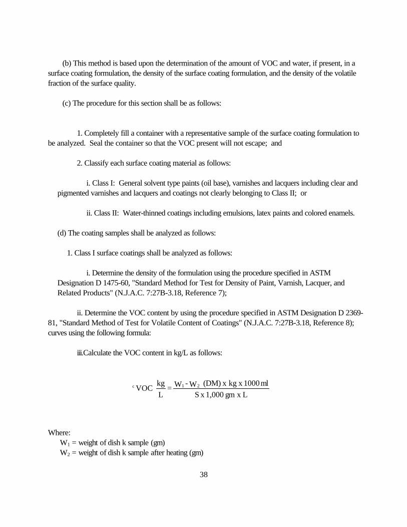
iii.Calculate the VOC content in kg/L as follows:
Where: W1 = weight of dish k sample (gm) W2 = weight of dish k sample after heating (gm)
L x gm 1,000 x Sml1000 x kg x (DM) W - W =
Lkg
VOC 21c

39
DM = density of coating (gm/ml) S = sample weight (gm) L = liters
iv. Sources included in a mathematical combination regulated by N.J.A.C. 7:27-16.5(a) shall beanalyzed as follows:
(1) Separate the volatile fraction from the solids either by high speed centrifuge, ASTMD2698-73, "Standard Test Method for the Determination of the Pigment Content of SolventReducibic Paints by High Speed Centrifuging" (N.J.A.C. 7:27B-3.18, Reference 12), or bydistillation, ASTM D95-83, "Standard Test Method for Determining Water in Petroleum andBituminous Materials by Distillation" (N.J.A.C. 7:27B-3.18, Reference 13). ASTM D95-83 shall bemodified by not adding the required solvent and continuing the distillation until the sample is dry. Measure the volume V and the weight W of the volatile fraction (see Appendix I);
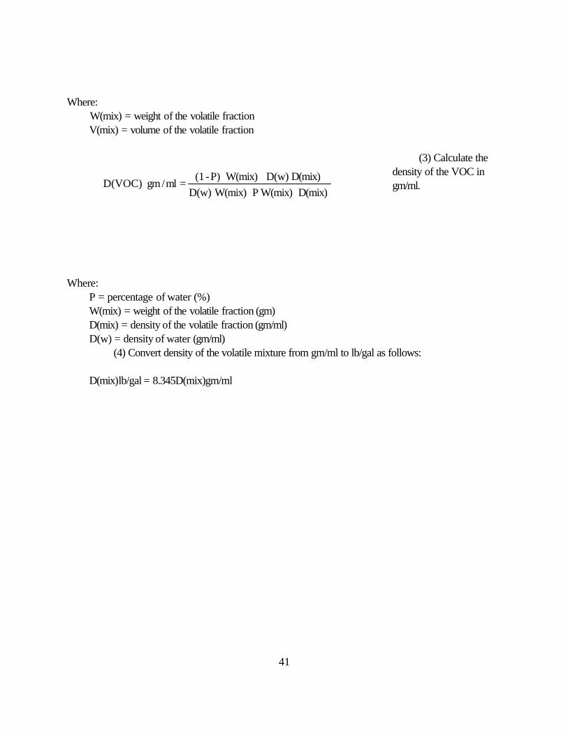
(2) Calculate the density of the VOC fraction in gm/ml as follows:
Where:W = weight of the volatile fractionV = volume of the volatile fraction(3) Convert density VOC from gm/ml to lb/gal as follows:D(voc)lb/gal = 8.345 D(VOC) gm/ml
2. Class II surface coatings shall be analyzed as follows:
i. Determine the density of the formulation using the procedure specified in ASTM Designation D1475-60, "Standard Method for Test for Density of Paint, Varnish, Lacquer, and Related Products"(N.J.A.C. 7:27B-3.18, Reference 7);
ii. Determine the water content of the formulation using the procedure specified in ASTM D4017-81,"Standard Test Method for Water in Paints and Paint Materials" by Karl Fisher (N.J.A.C. 7:27B-3.18,Reference 9);
iii. Determine the VOC content by using the procedure specified in ASTM Designation D2369-81,"Standard Method of Test for Volatile Content of Coatings" (N.J.A.C. 7:27B-3.18, Reference 8);
iv. Calculate the VOC content in kg VOC per liter of coating less water as follows:
VW
= D(voc)

40
Where: W1 = weight of dish k sample (gm) W2 = weight of dishk sample after heating (gm) P = percentage of water (%) Dm = density of coating (gm/ml) DH = density of water (gm/ml) S = sample weight (gm) L = liter
Convert VOC content from kg/1 to lb/gal as follows:
v. Sources included in a mathematical combination shall be analyzed as follows:
(1) Separate the volatile fraction (including water if present) from the solids either by highspeed centrifuge, using ASTM D2698-73, "Standard Test Method for the Determination of Pigment,Content of Solvent Reducibly Paints by High Speed Centrifuging" (N.J.A.C. 7:27B-3.18, Reference 12),or by distillation, ASTM D95-83, "Standard Test Method for Determining Water in Petroleum andBituminous and Materials by Distillation" (N.J.A.C. 7:27B-3.18, Reference 13). ASTM D95-83 shall bemodified by not adding the required solvent and continuing the distillation until the sample is dry and bypurging the distillation apparatus with 5-10 CC/min air or nitrogen. Measure the volume V (mix) and theweight W (mix) of the volatile fraction. See Appendix I.
(2) Calculate the density of the volatile fraction in gm/ml.
L x gm 1000 x S
1000 x kg x Dm x Dh
D P.01 - (1PS 0.1 - W - W
= Lkg
x VOC
m
21
c
L8.345 x kg VOC =
gallb
x VOC c
c
V(Mix)W(Mix)
=D(Mix)
41
Where: W(mix) = weight of the volatile fraction
V(mix) = volume of the volatile fraction
(3) Calculate thedensity of the VOC ingm/ml.
Where: P = percentage of water (%) W(mix) = weight of the volatile fraction (gm) D(mix) = density of the volatile fraction (gm/ml) D(w) = density of water (gm/ml)
(4) Convert density of the volatile mixture from gm/ml to lb/gal as follows:
D(mix)lb/gal = 8.345D(mix)gm/ml
D(mix) W(mix)P W(mix)D(w)D(mix) D(w) W(mix)P)-(1
= ml/gm D(VOC)

42
N.J.A.C. 7:27B-3.11 Procedures for the determination of volatile organic compounds emittedfrom transfer operations using a flame ionization detector (FID) or non-dispersive infraredanalyzer (NDIR)
(a) The procedure in this section is applicable for the determination of the mass emission of VOCrates from the transfer or loading of gasoline. Any alternative test method shall be submitted to theDepartment for review pursuant to N.J.A.C. 7:27B-3.2(c), (d) and (e).
(b) This method is based upon one of the following two principles:
1. Flame Ionization, which involves ionization produced when the VOC in the sample is combusted ina hydrogen flame. The ions and electrons formed in the flame enter an electrode gap, decrease the gapresistance, and thus permit a current flow in an external circuit. The resulting current is proportional to theinstantaneous concentration of the VOC; or
2. Non-Dispersive Infra-Red, which involves absorption of infrared energy when a band of infraredenergy containing the proper frequencies is alternately passed through an absorption cell containing theorganic vapor and a reference cell. The difference in absorption between the reference cell and theabsorption cell containing the organic vapor is proportional to the instantaneous concentration of theorganic vapor.
(c) The following is a summary of this method:
1. The instrument is calibrated with a propane or butane calibration gas to establish the response ofthe instrument. A representative sample of the VOC is drawn into the detector and the instrumentresponse is recorded on a strip chart recorder. The total gas flow rate and the volume of gasolinepumped are determined for each five minute period. The mass emission rate of VOC is calculated aspropane and the results are summed for each five minute period and reported as either percent controlefficiency or pounds of VOC per 10,000 gallons of gasoline transferred.
2. For the purpose of this procedure, three separate test runs will be conducted. Each test run shallbe conducted over a period of time during which at least 10,000 gallons of gasoline are transferred but inno case shall the test period be less than one hour in duration unless an alternative period shall besubmitted to the Department for review pursuant to N.J.A.C. 7:27B-3.2(c), (d) and (e).
3. During each test run, all flanges, valves, connections and fittings shall be tested for leaks using the testprocedures outlined in N.J.A.C. 7:27B-3.15.
(d) The following is a list of equipment used in this method:
1. Probe;

43
2. Temperature sensor;
3. Pump;
4. Flow meter: an appropriate flow measuring device as specified in EPA Method 2A or if testing avapor incinerator Method 2B (N.J.A.C. 7:27B-3.18, Reference 16);
5. Needle valve;
6. Detector, as set forth below:
i. Flame ionization detector: the instrument shall be capable of meeting manufacturer's specificationsby demonstration and those specifications listed in ii below;
ii. Non-Dispersive Infra-Red detector: the specifications are as follows:
(1) Linearity: the instrument response to propane or butane shall not deviate from linearity
by more than five percent of the full scale value of the range being used;
(2) Zero drift: less than five percent of full scale per test period or one hour whichever is less;
(3) Span drift: less than five percent of full scale per test period or one hour whichever is less; and
(4) Response time: less than or equal to 30 seconds for 95 percent full scale.
7. Gas supplies:
i. Calibration gases: three manufacturer's certified propane mixture in the range of 1,000; 10,000; and 100,000 ppm and a propane standard for leak determination as specified in N.J.A.C. 7:27B-3.15;
ii. Zero gas;
iii. Fuel gas; and
iv. Combustion gas.
8. Sample line: Teflon or stainless steel tubing with Teflon or stainless steel fittings.
(e) The procedure for this section shall be as follows:

44
1. Calibrate and install a pressure measurement device (liquid manometer, magnehelic gauge, orequivalent instrument), capable of measuring up to 500 mm of water gauge pressure with " 2.5 mm ofwater precision.
2. Connect the pressure measurement device to a pressure tap in the terminals vapor collection system,located as closely as possible to the connection with the gasoline tank truck.
3. During the performance test, record the pressure every five minutes while a gasoline tank truck isbeing loaded, and record the highest instantaneous pressure that occurs during each loading. Everyloading position shall be tested at least once during the performance test.
4. For the determination of volume at the exhaust vent, the following EPA reference methods shall beused (N.J.A.C. 7:27B-3.18, Reference 16):
i. Method 2B for combustion vapor processing systems; or
ii. Method 2A for all other vapor processing systems.
5. For the determination of VOC concentration at the exhaust vent, procedures outlined in N.J.A.C.7:27B-3.7 shall be used. The calibration gas shall be either propane or butane.
6. Immediately prior to a performance test all potential sources of vapor leakage in the terminal's vaporcollection system equipment shall be monitored for leaks using the procedures outlined in N.J.A.C.7:27B-3.15. The monitoring shall be conducted only while a gasoline tank truck is being loaded. Areading of 100 percent lower explosive limit or greater of propane shall be considered a leak. All leaksshall be repaired prior to conducting the performance test.
i. All testing equipment shall be prepared and installed as specified in the appropriate test methods.
7. The volume of gasoline dispensed during the performance test period at all loading racks whosevapor emissions are controlled by the processing system being tested shall be determined. This volumemay be determined from terminal records or from gasoline dispensing meters at each loading rack.
8. An emission testing interval shall consist of each five-minute period during the performance test. Foreach interval:
i. The reading from each measurement instrument shall be recorded; and
ii. The volume discharged and the average VOC concentration in the exhaust vent shall be determined,as specified in the appropriate test method. The average VOC concentration shall correspond to thevolume measurement and shall be adjusted by the sampling system response time.

45
9. Unless specified by the Department, each performance test shall consist of not less than threeseparate and valid test runs. Each test run shall be conducted over a period of time during which at least10,000 gallons of gasoline are transferred but in no case shall the test period be less than one hour induration.
10. To determine the efficiency of a control device, simultaneous tests shall be conducted on the vaporin the gaseous stream displaced from the receiving vessel upstream of any vapor control system and at theexhaust vent of the control system.
(f) The calculations shall be performed as follows:
1. Calculate the mass emitted during each testing interval as follows:
Where:
Cppm (as std) = parts per million of VOC as standard (propane or butane).
MW (std) = molecular weight of standard (propane or butane).
SCFM = Cubic feet per minute at 70oF and 1 atm emitted by the source.
387 = molar volume at standard conditions in cubic feet per pound-mol.
2. Calculate the total VOC emitted during the test period by summing the lbs. VOC per each testinterval as calculated in 1 above.
3. Calculate the efficiency of the emission control system as follows:
4. Calculatethe total emission rate of the VOC in lbs per 10,000 gallons of gasolinetransferred as follows:
10 x 387MW(std) x SCFMmin x 5 x std) (as Cppm
= interval Less
VOC lbs 6
inlet) (lbs/test 100 x outlet)lbs/test -inlet (lbs/test
= Efficiency %
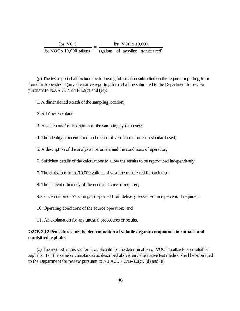
46
(g) The test report shall include the following information submitted on the required reporting formfound in Appendix B (any alternative reporting form shall be submitted to the Department for reviewpursuant to N.J.A.C. 7:27B-3.2(c) and (e)):
1. A dimensioned sketch of the sampling location;
2. All flow rate data;
3. A sketch and/or description of the sampling system used;
4. The identity, concentration and means of verification for each standard used;
5. A description of the analysis instrument and the conditions of operation;
6. Sufficient details of the calculations to allow the results to be reproduced independently;
7. The emissions in lbs/10,000 gallons of gasoline transferred for each test;
8. The percent efficiency of the control device, if required;
9. Concentration of VOC in gas displaced from delivery vessel, volume percent, if required;
10. Operating conditions of the source operation; and
11. An explanation for any unusual procedures or results.
7:27B-3.12 Procedures for the determination of volatile organic compounds in cutback and emulsified asphalts
(a) The method in this section is applicable for the determination of VOC in cutback or emulsifiedasphalts. For the same circumstances as described above, any alternative test method shall be submittedto the Department for review pursuant to N.J.A.C. 7:27B-3.2(c), (d) and (e).
red) transfergasoline of (gallons10,000 x VOC lbs
= gallons 10,000 x VOC lbs
VOC lbs
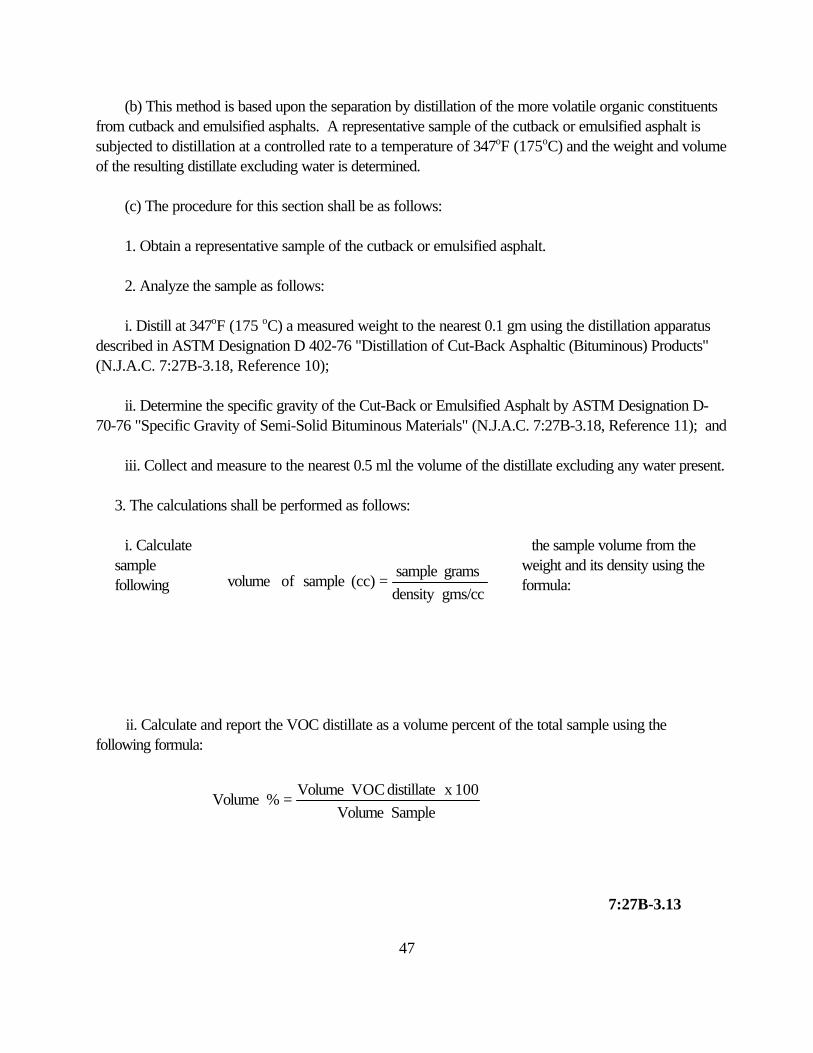
47
(b) This method is based upon the separation by distillation of the more volatile organic constituentsfrom cutback and emulsified asphalts. A representative sample of the cutback or emulsified asphalt issubjected to distillation at a controlled rate to a temperature of 347oF (175oC) and the weight and volumeof the resulting distillate excluding water is determined.
(c) The procedure for this section shall be as follows:
1. Obtain a representative sample of the cutback or emulsified asphalt.
2. Analyze the sample as follows:
i. Distill at 347oF (175 oC) a measured weight to the nearest 0.1 gm using the distillation apparatusdescribed in ASTM Designation D 402-76 "Distillation of Cut-Back Asphaltic (Bituminous) Products"(N.J.A.C. 7:27B-3.18, Reference 10);
ii. Determine the specific gravity of the Cut-Back or Emulsified Asphalt by ASTM Designation D-70-76 "Specific Gravity of Semi-Solid Bituminous Materials" (N.J.A.C. 7:27B-3.18, Reference 11); and
iii. Collect and measure to the nearest 0.5 ml the volume of the distillate excluding any water present.
3. The calculations shall be performed as follows:
i. Calculate the sample volume from thesample weight and its density using thefollowing formula:
ii. Calculate and report the VOC distillate as a volume percent of the total sample using thefollowing formula:
7:27B-3.13
gms/ccdensity grams sample
= (cc) sample of volume
Sample Volume100 x distillate VOC Volume
= % Volume

48
Procedures for the determination of leak tightness of gasoline delivery vessels
(a) The method in this section is applicable for the determination of the leak tightness of gasolinedelivery vessels. For the same circumstances as described above, any alternative test method shall besubmitted to the Department for review pursuant to N.J.A.C. 7:27B-3.2(c), (d) and (e).
(b) This method is based upon the application of a pressure/vacuum to the compartment(s) of agasoline delivery vessel and the measurement of the change in pressure/vacuum over a period of time.
(c) The following is a list of equipment used in this method:
1. Pressure source: pump or compressed gas cylinder of air or inert gas sufficient to pressurize thedelivery vessel to 25 inches of water (47 millimeters of mercury);
2. Regulator: low pressure regulator for controlling the pressurization of the delivery vessel;
3. Vacuum source: vacuum pump capable of evacuating the delivery vessel to 10 inches of water(19 millimeters of mercury)
4. Manometer: liquid manometer, or equivalent, capable of measuring up to 25 inches of water (47millimeters of mercury) with " 0.1 inch water (02 millimeters of mercury) precision;
5. Test cap for vapor recovery hose fittings: a cap shall be equipped with a tap for the manometerconnection and shall be equipped with a shut-off valve for connection to the pressure/vacuum source; and
6. Pressure/vacuum relief valves: the test apparatus shall be equipped with an in-linepressure/vacuum relief valve set to activate at 28 inches of water (53 millimeters of mercury) aboveatmospheric pressure and 12 inches of water (23 millimeters of mercury) below atmospheric pressure. The valves shall have a flow capacity greater than or equal to the pressurizing or evacuating pump rates.
(d) The following pretest conditions shall be met:
1. The delivery vessel shall be purged of gasoline vapors and tested empty; and
2. The delivery vessel shall be tested where it will be protected from the sun.
(e) The procedure for this section shall be as follows:
1. The dome covers are to be opened and then closed;
2. Connect static electrical ground connections to the delivery vessel. Attach the delivery and vaporhoses, remove the delivery elbows, and plug the liquid delivery fittings;

49
3. Attach the test cap to the vapor recovery line of the delivery vessel;
4. Connect the compartments of the delivery vessel internally to each other (if connecting thecompartments internally is not possible, each compartment shall be tested separately);
5. Connect the pressure/vacuum supply hose and the pressure/vacuum relief valve to the shut-offvalve. Attach the pressure source to the hose. Attach a manometer to the pressure tap;
6. Open the shut-off valve in the vapor recovery hose cap. Applying air pressure slowly, pressurizethe delivery vessel to 18 inches of water (34 millimeters of mercury);
7. Close the shut-off valve and allow the pressure in the delivery vessel to stabilize. Adjust thepressure, if necessary, to maintain 18 inches of water (34 millimeters of mercury). When the pressurestabilizes, record the time and initial pressure; and
8. At the end of five minutes, record the final pressure.
9. Repeat steps 6 through 8 above until the pressure for two consecutive runs agrees to within "12.5 mm water.
10. Disconnect the pressure source from the pressure/vacuum supply hose, and slowly open theshut-off valve to bring the tank to atmospheric pressure;
11. Connect the vacuum source to the pressure/vacuum supply hose;
12. Slowly evacuate the tank to six inches of water (11 millimeters of mercury);
13. Close the shut-off valve and allow the pressure in the delivery vessel to stabilize. Adjust thepressure, if necessary, to maintain six inches of water (11 millimeters of mercury) vacuum. When thepressure stabilizes, record the time and initial pressure; and
14. At the end of five minutes, record the time and final pressure.
15. Repeat steps 6 through 14 for each compartment if these were not interconnected.
16. Alternate methods for purging and pressurizing shall be submitted for review by the Departmentpursuant to N.J.A.C. 7:27B-3.2(c), (d) and (e). See Appendix G for the required reporting form (anyalternative reporting form shall be submitted to the Department for review, pursuant to N.J.A.C. 7:27B-3.2(c) and (e)).

50
N.J.A.C. 7:27B-3.14, Procedures for the direct detection of fugitive volatileorganic compound leaks.
7:27B-3.14 Procedures for the direct detection of fugitive volatile organic compound leaks
(a) The method in this section is applicable for the detection of fugitive VOC leaks. Any alternativetest method shall be submitted to the Department for review pursuant to N.J.A.C. 7:27B-3.2(c), (d) and(e).
(b) This method is based upon the detection of VOC leaks from individual sources by a portableinstrument. The instrument detector type is not specified but shall meet the performance criteria of (d)4below. This procedure is intended to locate and classify leaks only and shall not be used to measure massemission rates from individual sources.
(c) The following is a summary of this method:
1. The detector is calibrated with a standard gas mixture to establish the response of the instrument. A representative sample of fugitive emissions is drawn into the instrument. The response is read directlyfrom the instrument meter.
2. For purposes of this procedure a single test shall be sufficient to establish the presence of a leak.
(d) The following is a list of equipment used in this method:
1. Probe: glass, stainless steel, or Teflon tubing as required by source gas conditions and equippedwith 0.4 inch (one centimeter) tip spacer;
2. Pump: a leakless Teflon-coated diaphragm pump capable of maintaining an appropriate flow tothe detector;
3. Dilutor: (if circumstances require) capable of diluting the sample gas into the range of theinstrument such that concentration levels of 10,000 ppm can be measured. The dilutor tip shall beequipped with a 0.4 inch (one centimeter) spacer;
4. Monitoring instrument, as set forth below:
i. The monitoring instrument shall be certified as safe for operation in explosive atmospheres;

51
ii. The monitoring instrument detector shall be capable of measuring the leak concentration specifiedin the appropriate section in N.J.A.C. 7:27-16. Detector types which meet this requirement include butare not limited to catalytic oxidation, flame ionization, infra-red absorption, and photoionization; and
iii. The instrument shall be readable to within five percent of the specified leak concentration and shallhave a response time less than or equal to of 30 seconds for 95 percent of scale;
5. Standard calibration gas--8,000 ppmv Hexane or Methane in air.
(e) The procedure for this section shall be as follows:
1. A presampling survey shall be conducted to locate components where potential leaks could occur;
2. Calibration shall be conducted as follows:
i. The instrument should be operated according to the manufacturer's directions;
ii. Adjust the analyzer to zero by using ambient air; and
iii. Introduce the 8,000 ppm calibration gas into the instrument sample probe. Adjust the instrumentmeter readout and chart recorder to correspond to the calibration value. If necessary, use a dilutionsystem to bring the calibration gas into the instrument range.
3. Sampling and analyses shall be conducted as follows:
i. Place the instrument probe with the 0.4 inch (one centimeter) spacer at the surface of thecomponent interface where leakage is suspected. Move the probe along the interface periphery whileobserving the instrument readout. If an increased meter reading is observed, slowly probe the interfacewhere leakage is indicated until the maximum meter reading is obtained. Leave the probe at themaximum reading location for approximately two times the instrument response time. If theconcentration reading is in excess of the range of the instrument, add the dilution assembly and sampleas above using a correction factor to convert the measurements to the undiluted bases. Record thedate, time and identity of the leaking components. See Appendix F for the required reporting form. (Any alternative form shall be submitted to the Department for review pursuant to N.J.A.C. 7:27B-3.2(c) and (e).)
7:27B-3.15 Procedures for the direct detection of fugitive volatile organic compound leaksfrom gasoline tank trucks and vapor collection systems using a combustible gas detector

52
(a) The method in this section is applicable for the detection of fugitive VOC leaks from gasolinetank trucks and vapor collection systems. For the same circumstances as described above, anyalternative test method shall be submitted to the Department for review pursuant to N.J.A.C. 7:27B-3.2(c), (d) and (e).
(b) This method is based upon the detection of VOC leaks from individual sources by a portableinstrument. The instrument detector type is not specified but must meet the performance criteria ofN.J.A.C. 7:27B-3.14(d)4. This procedure is intended to locate and classify leaks only and shall notbe used as a measure of mass emission rates from individual sources.
(c) The following is a summary of this method:1. The detector is calibrated with a standard gas mixture to establish the response of the
instrument. A representative sample of the fugitive emissions is drawn into the instrument. Theresponse is read directly from the instrument meter.
2. For purposes of this procedure a single test shall be sufficient to establish the presence of aleak.
(d) The following is a list of equipment used in this method:
1. Probe: glass, stainless steel, or Teflon tubing as required by source gas conditions andequipped with a 1.0 inch (2.54 centimeter) tip spacer;
2. Pump: a leakless Teflon-coated diaphragm pump or other suitable pump capable ofmaintaining an appropriate flow to the detector;
3. Monitoring instrument as set forth below:
i. The monitoring instrument shall be certified as safe for operation in explosive atmosphere;
ii. The monitoring instrument detector shall be capable of measuring the leak concentrationspecified in the appropriate section of N.J.A.C. 7:27-16. Detector types meeting thisrequirement include but are not limited to catalytic oxidation, flame ionization, infra-redabsorption, and photoionization; and
iii. The instrument shall be readable to within five percent of the specified leakconcentration and shall have a response time of 30 seconds or less;
4. Standard calibration gas--at least 50 percent but less than 100 percent LEL of propane in air.

53
(e) The procedure for this section shall be as follows:
1. A presampling survey shall be conducted to locate components where potential leaks couldoccur;
2. Calibration shall be conducted as follows:
i. The instrument shall be operated according to the manufacturer's directions;
ii. Adjust the analyzer to zero according to the manufacturer's instructions; and
iii. Introduce the standard calibration gas into the instrument sample probe. Adjust the instrumentmeter readout to obtain the correct response. If unable to obtain the correct response within " fivepercent the instrument is unacceptable for use.
3. Sampling and Analysis shall be conducted as follows:
i. All leak testing shall be done during a loading operation;
ii. Place the instrument probe with the 1.0 inch (2.54 centimeters) spacer at the surface of thecomponent interface where leakage could occur. Move the probe along the interface periphery whileobserving the instrument readout. If an increased meter reading is observed, slowly probe the interfacewhere leakage is indicated until the maximum reading is obtained. Leave the probe at the maximumreading location for approximately two times the instrument response time. If the concentration readingis in excess of the range of the instrument, add the dilution assembly and sample as above using acorrection factor to convert the measurements to the undiluted basis. Record the date, time, amount,and identity of the leaking components. See Appendix F for the required reporting form. (Anyalternative reporting form shall be submitted to the Department for review pursuant to N.J.A.C.7:27B-3.2(c) and (e).)
7:27B-3.16 Procedures for determining the efficiency of gasoline vapor recovery systems atservice stations
(a) The method for this section is applicable for the determination of the efficiency of vaporrecovery systems controlling gasoline vapors emitted during the filling of underground storage tanks.

54
For the same circumstances as described above, any alternative method shall be submitted to theDepartment for review pursuant to N.J.A.C. 7:27B-3.2(c), (d) and (e).
(b) This method is based upon the amount of gasoline vapor discharged from the atmosphericvent(s) of underground storage tank(s) being filled. The procedure is intended for all control systemswhich have a vapor recovery line connecting the underground storage tank to the tank truck.
(c) The following is a summary of this method:
1. A positive displacement meter is mounted on each atmospheric vent pipe to determine theamount of vapor displaced during the filling of underground storage tanks. The efficiency of the vaporrecovery system is determined by comparing the amount of vapor emitted from the atmospheric ventswith the total amount of gasoline transferred to the underground storage tanks.
2. For the purpose of this procedure, a single test shall be sufficient to establish the efficiency ofthe vapor recovery system.
(d) The following is a list of equipment used in this method:
1. Gas meter device: a positive displacement meter with a capacity of 3000 SCFH and apressure drop of 0.05 inches of water at an air flow of 30 SCFH. This meter shall be designed to read(in 0.1 cubic foot increments) only the amount of positive vapors displaced and shall allow for anynegative in-breathing. The meter shall be equipped with taps for a thermocouple and a pressuresensor;
2. Coupling for atmospheric vent pipe: a coupling to connect the gas metering device to theatmospheric vent pipe. Coupling shall be sized for a minimum pressure drop;
3. Thermocouples: temperature sensing devices to measure the temperature of the vapors emittedat the gas metering device and ambient temperature; and
4. Manometer: liquid manometer or other equivalent pressure sensing device capable ofmeasuring zero to ten inches of water at the gas metering device.
5. Leak detection equipment standards shall be as follows:
i. The leak detection equipment shall be certified as safe for operation in explosive atmospheres;
ii. The monitoring instrument detector shall be capable of measuring the leak definitionconcentration specified in the appropriate section in N.J.A.C. 7:27-16. Detector types meeting this

55
requirement include but are not limited to catalytic oxidation, flame oxidation, infrared absorption andphotoionization; and
iii. The instrument shall be readable to within five percent of the specific leak concentration andshall have a response time of 30 seconds or less.
(e) The procedure for this section shall be as follows:
1. Mount the positive displacement meter to the top of the atmospheric vent of the storage tank(s). If the vent has restriction, remove the restriction before mounting the meter;
2. Connect the manometer and thermocouple to the taps on the meter;
3. Connect tank truck fuel and vapor return hoses to the underground storage tanks in accordancewith procedures outlined by the manufacturer;
4. Check the tank truck and all vapor return line connections with a leak detection instrument for atight seal before and during the test;
5. Record the initial reading of the gas meter(s);
6. Start the transfer of gasoline to the storage tank(s) in accordance with facilities' establishednormal procedures;
7. Record temperature, pressure, and gas meter readings at two minute intervals;
8. Record at the start and the end of the test the barometric pressure and ambient temperature;
9. Disconnect the tank truck hoses from the storage tank in accordance with the proceduresoutlined by the facility when the transfer has been completed;
10. Continue to record temperature, pressure, and gas meter readings at the underground storagetank vent(s) at two-minute intervals for a period of ten minutes after the completion of the gasolinetransfer;
11. Record the final reading of the gas meter;
12. Record the total volume of gasoline that was transferred; and
13. Disconnect the positive displacement meter from the atmospheric vent.
(f) Calculate the efficiency of the vapor recovery system using the following equation:

56
Where:
E = Percent efficiency of the vapor recovery system at standard conditions.
V v = Volume of displaced vapors vented from the atmospheric vent in actual cubic feet (ACF).
VT = Volume of gasoline transferred to storage tanks in gallons.
Tv = Temperature of vapors vented from atmospheric vent in degrees Fahrenheit.
Ts = Standard temperature (70° F).
Pb = Average barometric pressure during test in inches of mercury.
7.481 = Conversion factor of gallons per cubic foot (Gal/ft3).
29.92 = Standard pressure in inches of mercury.
(g) The test report shall include the following information submitted on the required reporting formslisted in Appendix H. (Any alternative report form shall be submitted to the Department for reviewpursuant to N.J.A.C. 7:27B-3.2(c) and (e)):
1. A dimensioned sketch of the sampling location detailing number of storage tanks, type of fill pipe; and type of vapor recovery system;
2. The total amount of each type of gasoline transferred;
3. The size of the storage tank(s) into which the gasoline was transferred;
4. The total amount of gasoline present in the storage tank(s) prior to transfer;
5. Pressure/vacuum test date listed on the tank truck; and
(29.92) 460 + T( V
)P460)( + T(7.481)( V - 1 = Evt
bsv

57
6. Identification of the tank truck.
N.J.A.C. 7:27B-3.17, Procedures for the determination of volatile organic compounds emittedfrom petroleum solvent dry cleaning operations
(a) The method in this section is applicable for the determination of the final recovered solventflow rate at the completion of the recovery cycle, and the VOC content in all filtration waste. For thesame circumstances as described above, any alternative method shall be submitted to the Departmentfor review, pursuant to N.J.A.C. 7:27B-3.2(c), (d), and (e).
(b) This method is based upon:
1. The determination of the volume of the recovered solvent; and
2. The separation and weight determination of the solvent.
(c) The following is a summary of this method:
1. The recovered solvent is diverted to a graduated cylinder at the end of the recovery cycle. Thevolume of solvent recovered during a one minute period is measured and recorded.
2. The recovered solvent is separated from other filtration waste and weighed.
(d) The procedure for this section shall be as follows:
1. Recovered solvent shall be determined as follows:
i. The flow rate of the recovered solvent is measured at the outlet of the solvent-water separator;
ii. The flow rate of the recovered solvent is measured at the end of the solvent recovery phase;
iii. Divert the flow of the recovered solvent to a graduated cylinder;
iv. Record the volume of recovered solvent to the nearest milliliter, after a one minute interval;
v. Record the type of articles cleaned and the length of the recovery cycle; and
vi. Repeat steps i-v over three cleaning cycles.

58
2. The solvent content in filtration waste shall be determined as follows:
i. Collect three one-kilogram samples of still and filtration waste in air-tight containers which areimpervious to petroleum solvents;
ii. Record the total mass of articles in kilograms cleaned since the last still boildown or filter change;
iii. Record the total mass of still and filter water in kilograms produced since the last waste removal;
iv. Determine the solvent content of the still and filter water using the procedure specified in ASTMD322-80, "Standard Test Method for Gasoline Dilutent in Used Gasoline Engine Oils by Distillation"(N.J.A.C. 7:27B-3.18, Reference 15); and
v. Report the results as mass of VOC per mass of dry weight of articles dry cleaned in kilogramsper kilogram.
7:27B-3.18 Test methods and sources incorporated by reference
(a) The following sources and test methods are incorporated by reference in this subchapter:
1. New Jersey Administrative Code Title 7, Chapter 27B-1, AIR TEST METHOD 1 is availablefrom New Jersey Department of Environmental Protection, John Fitch Plaza, CN 027, Trenton, NewJersey 08625. (Free)
2. Code of Federal Regulations, Title 29, Chapter XVII, Parts 1910 and 1926 are available fromthe Occupational Safety and Health Administration, U.S. Department of Labor, 1515 Broadway, NewYork, New York 10036.
3. Code of Federal Regulations, Title 40, Part 80, Appendix E--"Method 1--Dry RVPMeasurement Method" and "Method 2--Herzog Semi-Automatic Method" are available from theSuperintendent of Documents, Government Printing Office, Washington, D.C. 20402.
4. ASTM Designation D2879-75, Standard Method for Test for Vapor Pressure--TemperatureRelationship and Initial Decomposition Temperature of Liquids by Isoteniscope, American Society forTesting and Materials, 1916 Race Street, Philadelphia, PA 19103 ($4.00).
5. API (American Petroleum Institute) Bulletin 2517, Selecting the Proper Nomograph, 156William Street, New York, New York 10038.

59
6. ASTM Designation D2551-80, Standard Method of Test for Vapor Pressure of PetroleumProducts (micromethod), American Society for Testing and Materials, 1916 Race Street, Philadelphia,PA 19103 ($4.00).
7. ASTM Designation D1475-60, Standard Method of Test for Density of Paint, Varnish,Lacquer, and Related Products, American Society for Testing and Materials, 1916 Race Street,Philadelphia, PA 19103 ($4.00).
8. ASTM Designation D2369-81, Standard Method of Test for Volatile Content of Coatings,American Society for Testing and Materials, 1916 Race Street, Philadelphia, PA 19103 ($4.00).
9. ASTM Designation D4017-81, Standard Test Method for Water in Paints and Paint Materialsby Karl Fischer Titration Method, American Society for Testing and Materials, 1916 Race Street,Philadelphia, PA 19103. ($4.00)
10. ASTM Designation D402-76, Standard Test Method for Distillation of Cut-Back Asphaltic(Bituminous) Products, American Society for Testing and Materials, 1916 Race Street, Philadelphia,PA 19103 ($4.00).
11. ASTM Designation D-70-76, Standard Test Method for Specific Gravity of Semi-SolidBituminous Materials, American Society for Testing and Materials, 1916 Race Street, Philadelphia,PA 19103 ($4.00).
12. ASTM Designation D2698-73, Standard Test Method for the Determination of the PigmentContent of Solvent Reducible Paints by High Speed Centrifuging, American Society for Testing andMaterials, 1916 Race Street, Philadelphia, PA 19103 ($4.00).
13. ASTM Designation D95-83, Standard Method for Determining Water in Petroleum andBituminous Materials by Distillation, American Society for Testing and Materials, 1916 Race Street,Philadelphia, PA 19103 ($4.00).
14. Method 2-1 California Air Resources Board, Test Procedures for Determining the Efficiencyof Gasoline Vapor Recovery Systems at Service Stations. Available from State of California, AirResources Board, 1102 Q Street, Sacramento, California 95812.
15. ASTM Designation D322-80, Standard Test Method for Gasoline Dilutent in Used GasolineEngine Oils by Distillation, American Society for Testing and Materials, 1916 Race Street,Philadelphia, PA 19103 ($4.00).
16. Code of Federal Regulations, Title 40, Part 60--Reference Methods 2A and 2B are availablefrom the Superintendent of Documents, Government Printing Office, Washington, D.C. 20402.
60
GENERAL NOTEEditor's Note: In addition to the above text, Appendices A through H were filed with these rules, butnot reproduced herein. Further information regarding these Appendices may be obtained bycontacting:
Bureau of Technical ServicesDivision of Environmental RegulationDepartment of Environmental ProtectionCN 437 (380 Scotch Road)Trenton, New Jersey 08625-0437