neutrons and x-rays in sustainable energy materials research · neutrons and x-rays in sustainable...
TRANSCRIPT
Neutrons and X-rays in Sustainable
Energy Materials Research
Michael Toney
Synchrotron Materials Sciences Division
Stanford Synchrotron Radiation Lightsource (SSRL)
SLAC National Accelerator Laboratory
http://www-ssrl.slac.stanford.edu/toneygroup
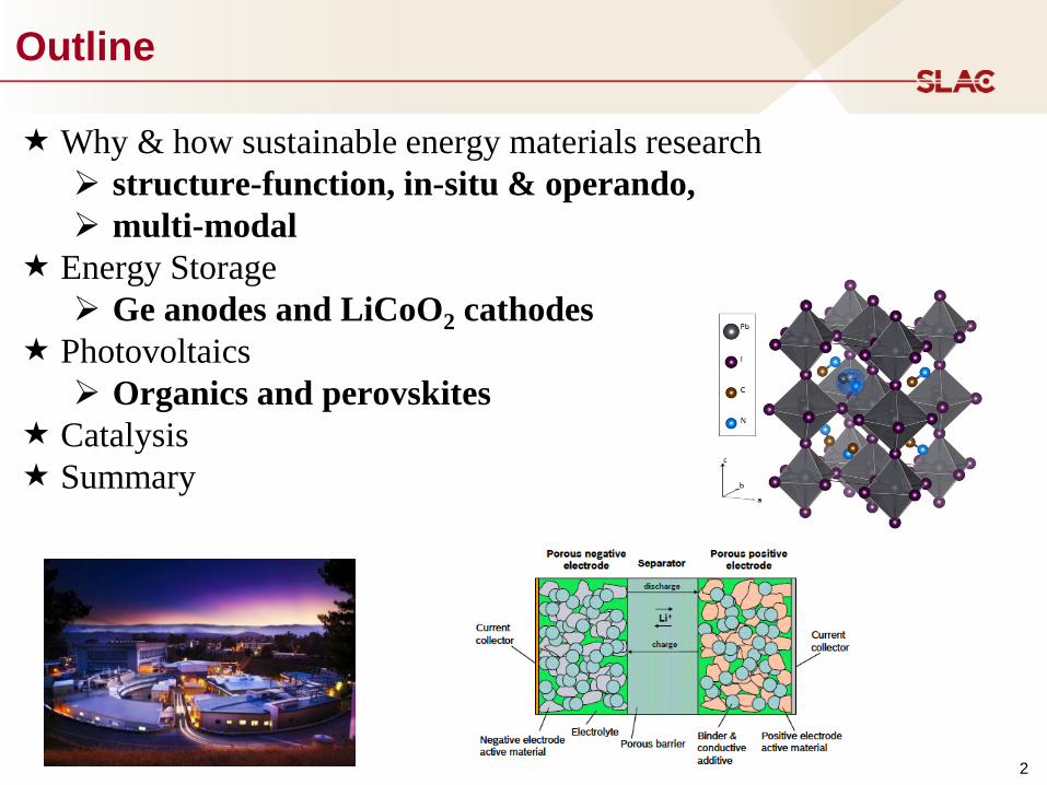
Outline
2
Why & how sustainable energy materials research
structure-function, in-situ & operando,
multi-modal
Energy Storage
Ge anodes and LiCoO2 cathodes
Photovoltaics
Organics and perovskites
Catalysis
Summary

3
Climate Change – One (Striking) Example
September 2012
3.5 million sq km
National Snow and Ice Data Center (NSIDC) http://nsidc.org/
4
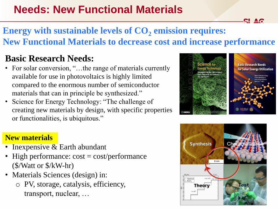
Needs: New Functional Materials
Basic Research Needs: • For solar conversion, “…the range of materials currently
available for use in photovoltaics is highly limited
compared to the enormous number of semiconductor
materials that can in principle be synthesized.”
• Science for Energy Technology: “The challenge of
creating new materials by design, with specific properties
or functionalities, is ubiquitous.”
New materials
• Inexpensive & Earth abundant
• High performance: cost = cost/performance
($/Watt or $/kW-hr)
• Materials Sciences (design) in:
o PV, storage, catalysis, efficiency,
transport, nuclear, …
Energy with sustainable levels of CO2 emission requires:
New Functional Materials to decrease cost and increase performance
5
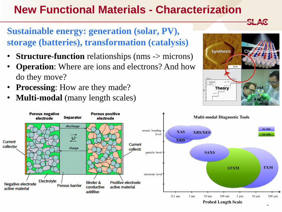
New Functional Materials - Characterization
• Structure-function relationships (nms -> microns)
• Operation: Where are ions and electrons? And how
do they move?
• Processing: How are they made?
• Multi-modal (many length scales)
Sustainable energy: generation (solar, PV),
storage (batteries), transformation (catalysis)
6
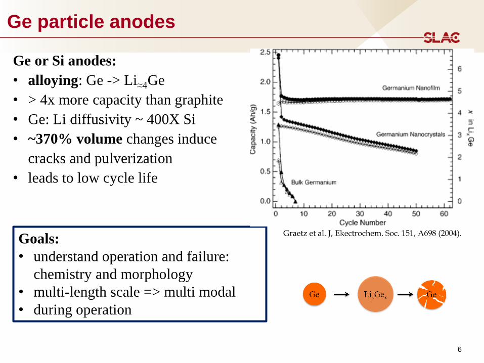
Ge particle anodes
Goals:
• understand operation and failure:
chemistry and morphology
• multi-length scale => multi modal
• during operation
Ge or Si anodes:
• alloying: Ge -> Li≈4Ge
• > 4x more capacity than graphite
• Ge: Li diffusivity ~ 400X Si
• ~370% volume changes induce
cracks and pulverization
• leads to low cycle life
Graetz et al. J, Ekectrochem. Soc. 151, A698 (2004).
7
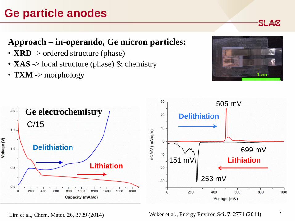
Ge particle anodes
Approach – in-operando, Ge micron particles:
• XRD -> ordered structure (phase)
• XAS -> local structure (phase) & chemistry
• TXM -> morphology
Lithiation
Delithiation
Ge electrochemistry 505 mV
253 mV
151 mV
699 mV
Lithiation
Delithiation C/15
1 cm
Lim et al., Chem. Mater. 26, 3739 (2014) Weker et al., Energy Environ Sci. 7, 2771 (2014)
8
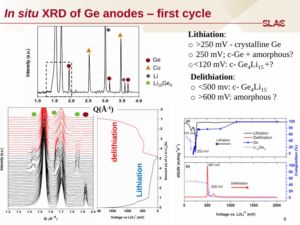
In situ XRD of Ge anodes – first cycle
Lithiation:
o >250 mV - crystalline Ge
o 250 mV; c-Ge + amorphous?
o<120 mV: c- Ge4Li15 +?
Delithiation:
o <500 mv: c- Ge4Li15
o >600 mV: amorphous ?
Ge
Cu
Li
Li15Ge4
deli
thia
tio
n
Lit
hia
tio
n
Q(Å-1)
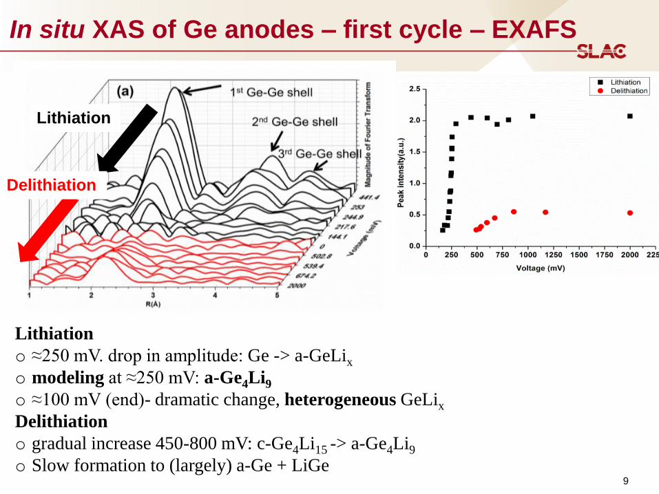
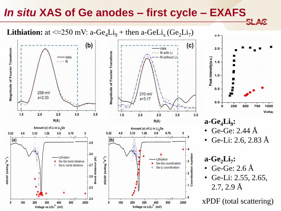
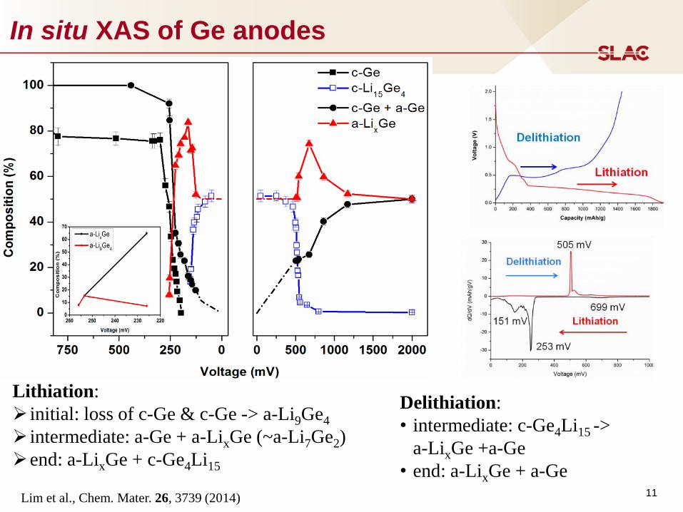
In situ XAS of Ge anodes – first cycle – EXAFS
9
Lithiation
Delithiation
Lithiation
o ≈250 mV. drop in amplitude: Ge -> a-GeLix
o modeling at ≈250 mV: a-Ge4Li9
o ≈100 mV (end)- dramatic change, heterogeneous GeLix
Delithiation
o gradual increase 450-800 mV: c-Ge4Li15 -> a-Ge4Li9
o Slow formation to (largely) a-Ge + LiGe
In situ XAS of Ge anodes – first cycle – EXAFS
Lithiation: at <≈250 mV: a-Ge4Li9 + then a-GeLix (Ge2Li7)
10
a-Ge4Li9:
• Ge-Ge: 2.44 Å
• Ge-Li: 2.6, 2.83 Å
a-Ge2Li7:
• Ge-Ge: 2.6 Å
• Ge-Li: 2.55, 2.65,
2.7, 2.9 Å
xPDF (total scattering)
11
In situ XAS of Ge anodes
Lithiation:
initial: loss of c-Ge & c-Ge -> a-Li9Ge4
intermediate: a-Ge + a-LixGe (~a-Li7Ge2)
end: a-LixGe + c-Ge4Li15
Delithiation:
• intermediate: c-Ge4Li15 ->
a-LixGe +a-Ge
• end: a-LixGe + a-Ge
Lim et al., Chem. Mater. 26, 3739 (2014)
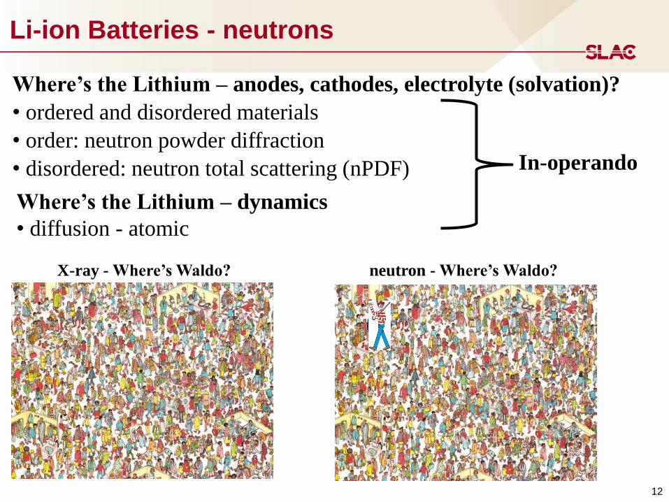
Li-ion Batteries - neutrons
12
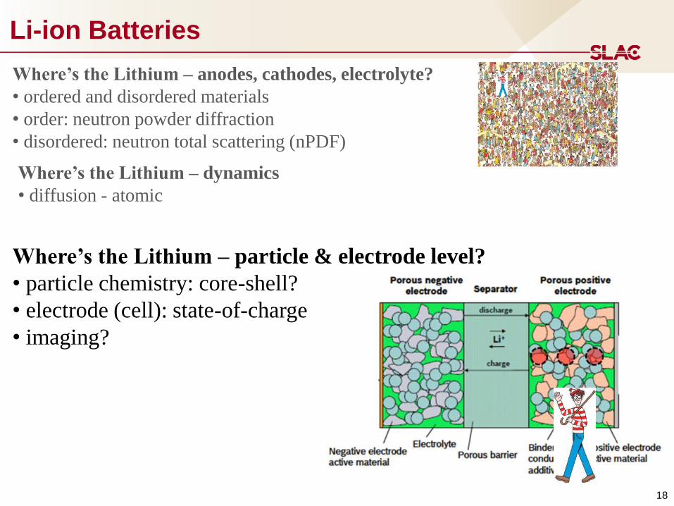
Where’s the Lithium – anodes, cathodes, electrolyte (solvation)?
• ordered and disordered materials
• order: neutron powder diffraction
• disordered: neutron total scattering (nPDF)
X-ray - Where’s Waldo? neutron - Where’s Waldo?
Where’s the Lithium – dynamics
• diffusion - atomic
In-operando
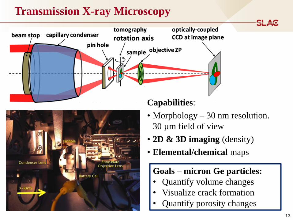
Transmission X-ray Microscopy
13
X-ray Microscopy
Capabilities:
• Morphology – 30 nm resolution.
30 µm field of view
• 2D & 3D imaging (density)
• Elemental/chemical maps
Goals – micron Ge particles:
• Quantify volume changes
• Visualize crack formation
• Quantify porosity changes

0
500
1000
1500
2000
2500
3000
0 500 1000 1500 2000
Po
ten
tial
vs
. L
i/L
i+ (
mV
)
Capacity (mA h/g)
1st cycle, C/5
Morphology changes during (de)lithiation
5 µm
1. Cracks form in larger particles (> 7.6 µm2 projected area or >3 µm diameter)
2. Cracks fill as lithiation continues
3. Cracks reappear during delithiation
4. After delithiation larger particles are porous
0.22
0.24
0.26
0.28
0.30
0.32
0.34
0 100 200 300 400 500 600 700
Pote
nti
al vs
. L
i/L
i+ a
t in
itia
l O
D d
rop
(V
)
Initial Area (µm2) 15
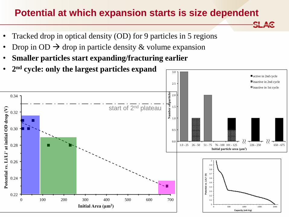
Potential at which expansion starts is size dependent
• Tracked drop in optical density (OD) for 9 particles in 5 regions
• Drop in OD drop in particle density & volume expansion
• Smaller particles start expanding/fracturing earlier
• 2nd cycle: only the largest particles expand
start of 2nd plateau
0
0.1
0.2
0.3
0.4
0.5
0.6
0.7
0.8
0.9
1
0 500 1000 1500 2000 P
ote
nti
al vs.
Li/L
i+ (
V)
Capacity (mA h/g)
0.0
0.5
1.0
1.5
2.0
2.5
3.0
1.0 - 25 26 - 50 51 - 75 76 - 100 101 - 125 226 - 250 650 - 675
Nu
mb
er o
f p
art
icle
s
Initial particle area (µm2)
active in 2nd cycle
inactive in 2nd cycle
inactive in 1st cycle
≈
≈
16
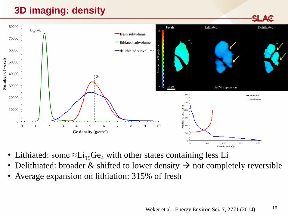
3D imaging: density
• Lithiated: some ≈Li15Ge4 with other states containing less Li
• Delithiated: broader & shifted to lower density not completely reversible
• Average expansion on lithiation: 315% of fresh
0
10000
20000
30000
40000
50000
60000
70000
80000
0 1 2 3 4 5 6 7 8 9 10
Nu
mb
er
of
vo
xel
s
Ge density (g/cm-3)
fresh subvolume
lithiated subvolume
delithiated subvolume
Ge
Li15Ge4
0
500
1000
1500
2000
2500
3000
0 500 1000 1500 2000
Pote
nti
al vs. L
i/L
i+ (
mV
)
Capacity (mA h/g)
1st lithiation
1st delithation
Weker et al., Energy Environ Sci. 7, 2771 (2014)
17
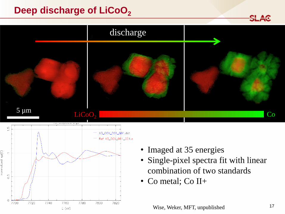
Deep discharge of LiCoO2
5 µm Co
discharge
LiCoO2
• Imaged at 35 energies
• Single-pixel spectra fit with linear
combination of two standards
• Co metal; Co II+
Wise, Weker, MFT, unpublished
Li-ion Batteries
18
Where’s the Lithium – anodes, cathodes, electrolyte?
• ordered and disordered materials
• order: neutron powder diffraction
• disordered: neutron total scattering (nPDF)
Where’s the Lithium – particle & electrode level?
• particle chemistry: core-shell?
• electrode (cell): state-of-charge
• imaging?
Where’s the Lithium – dynamics
• diffusion - atomic
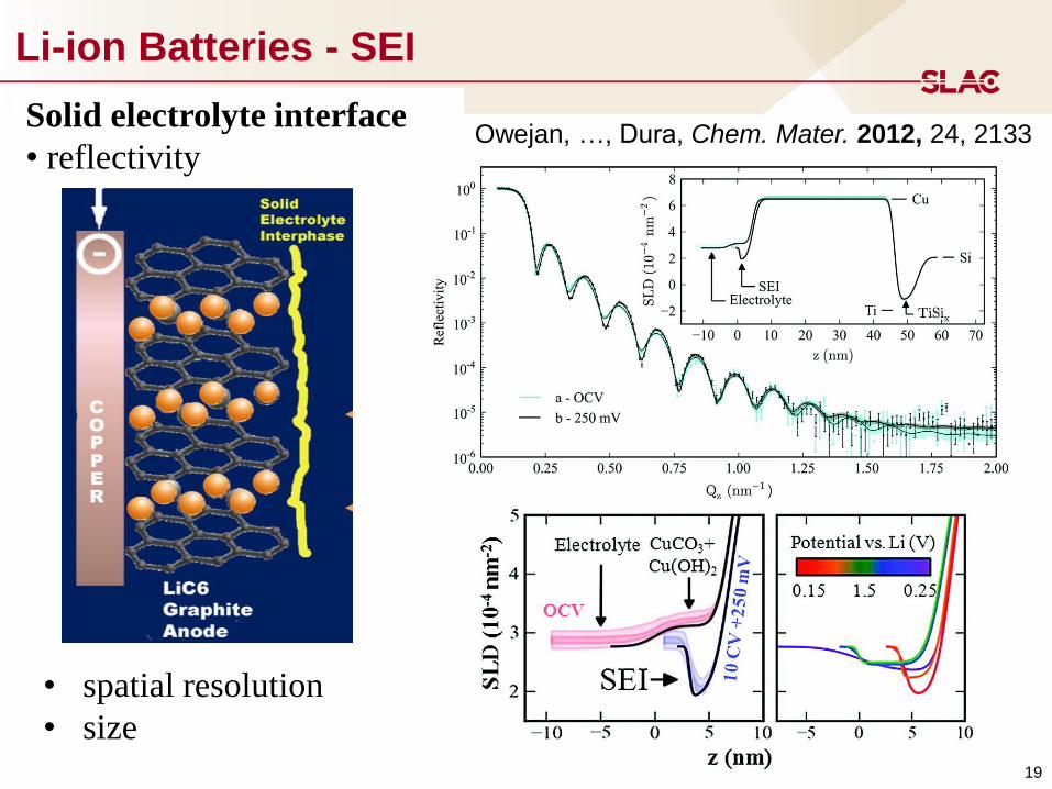
Li-ion Batteries - SEI
19
Solid electrolyte interface
• reflectivity Owejan, …, Dura, Chem. Mater. 2012, 24, 2133
• spatial resolution
• size
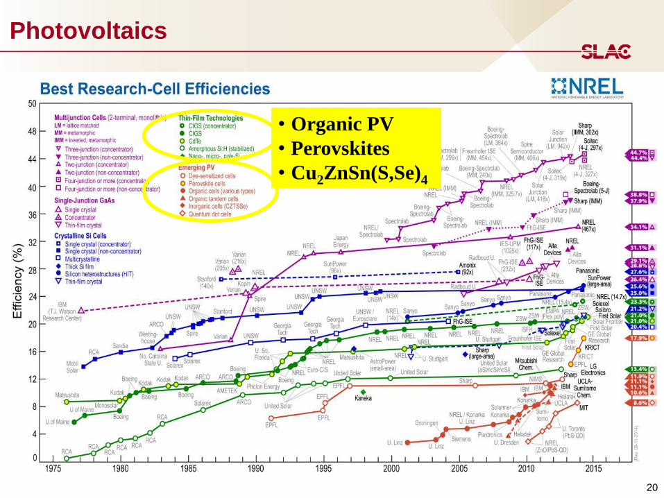
Photovoltaics
20
• Organic PV
• Perovskites
• Cu2ZnSn(S,Se)4
21
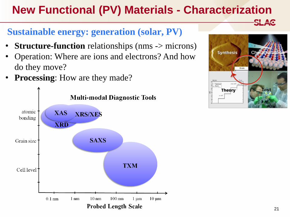
New Functional (PV) Materials - Characterization
• Structure-function relationships (nms -> microns)
• Operation: Where are ions and electrons? And how
do they move?
• Processing: How are they made?
Sustainable energy: generation (solar, PV)

Organic Solar Cells
22
Organic photovoltaic:
• Bulk heterojunction (BHJ)
• Light creates exciton (e- h+ pair)
• Exciton diffuses to donor/acceptor
interface & dissociates
• e- & h+ transport to electrodes
=> Power with PCE ≈ 10-12%
electrode
electrode
donor
acceptor
donor-acceptor interface
h+
e-
hν
Organic Solar Cells:
• flexible, solution processable
• inexpensive & mass production
• printing
acceptor: fullerene
phenyl-C61-butyric
ester (PC61BM)
& PC71BM
donor: semi-crystalline polymer
P3HT = poly(3-hexylthiophene)
PDPP2FT-C16
BHJs: 100s nm thick
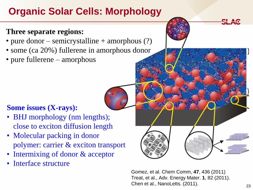
Organic Solar Cells: Morphology
23
Gomez, et al. Chem Comm, 47, 436 (2011)
Treat, et al., Adv. Energy Mater. 1, 82 (2011).
Chen et al., NanoLetts. (2011).
Three separate regions:
• pure donor – semicrystalline + amorphous (?)
• some (ca 20%) fullerene in amorphous donor
• pure fullerene – amorphous
Some issues (X-rays):
• BHJ morphology (nm lengths);
close to exciton diffusion length
• Molecular packing in donor
polymer: carrier & exciton transport
• Intermixing of donor & acceptor
• Interface structure
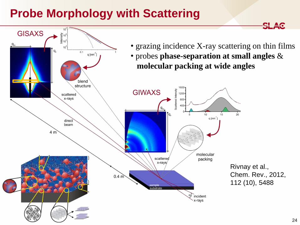
Probe Morphology with Scattering
24
• grazing incidence X-ray scattering on thin films
• probes phase-separation at small angles &
molecular packing at wide angles
Rivnay et al.,
Chem. Rev., 2012,
112 (10), 5488
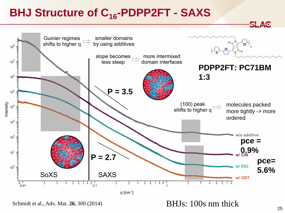
BHJ Structure of C16-PDPP2FT - SAXS
25
pce =
0.9%
P = 3.5
P = 2.7
PDPP2FT: PC71BM
1:3
molecules packed
more tightly -> more
ordered
pce=
5.6%
BHJs: 100s nm thick Schmidt et al., Adv. Mat. 26, 300 (2014)
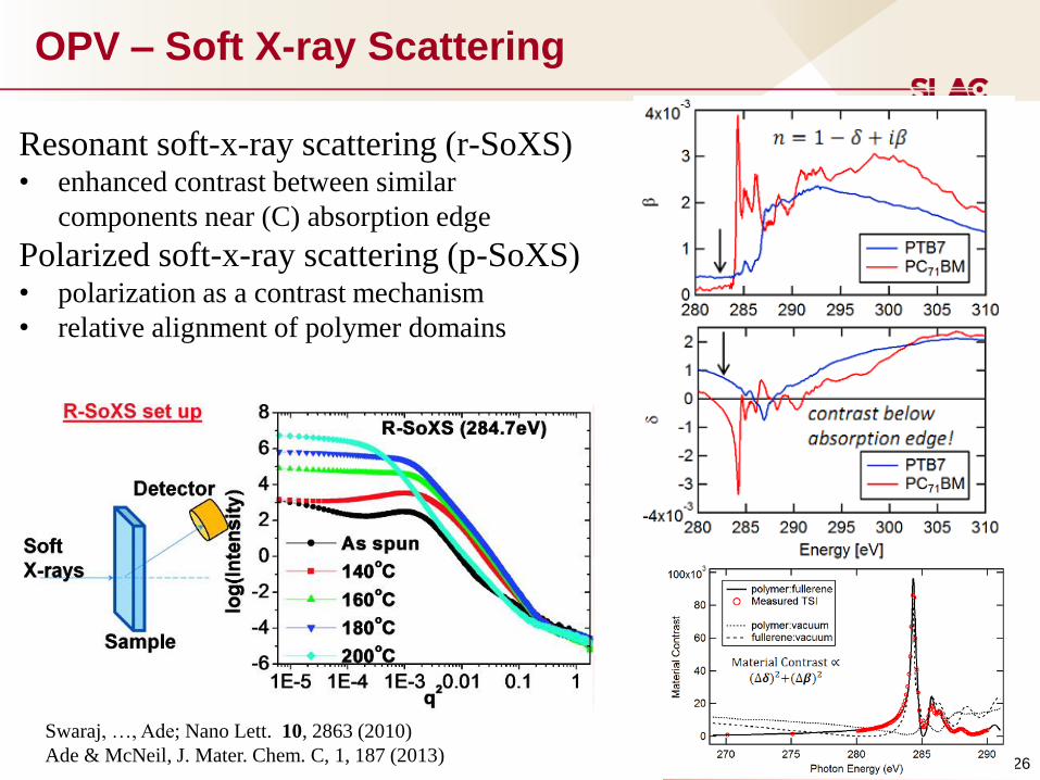
OPV – Soft X-ray Scattering
26
Resonant soft-x-ray scattering (r-SoXS) • enhanced contrast between similar
components near (C) absorption edge
Polarized soft-x-ray scattering (p-SoXS) • polarization as a contrast mechanism
• relative alignment of polymer domains
Swaraj, …, Ade; Nano Lett. 10, 2863 (2010)
Ade & McNeil, J. Mater. Chem. C, 1, 187 (2013)
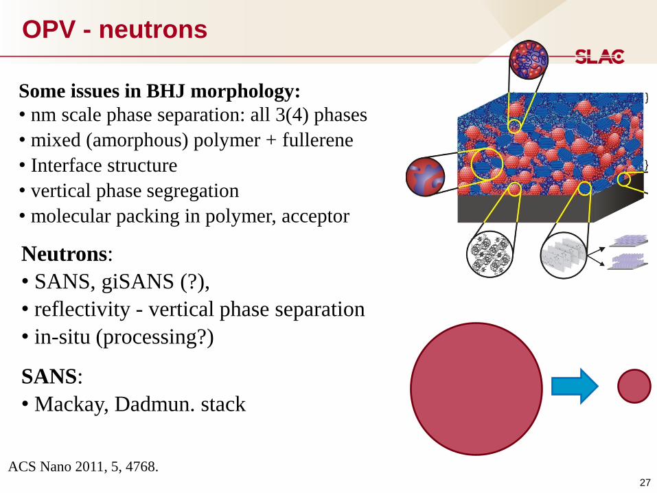
OPV - neutrons
27
Neutrons:
• SANS, giSANS (?),
• reflectivity - vertical phase separation
• in-situ (processing?)
Some issues in BHJ morphology:
• nm scale phase separation: all 3(4) phases
• mixed (amorphous) polymer + fullerene
• Interface structure
• vertical phase segregation
• molecular packing in polymer, acceptor
SANS:
• Mackay, Dadmun. stack
ACS Nano 2011, 5, 4768.
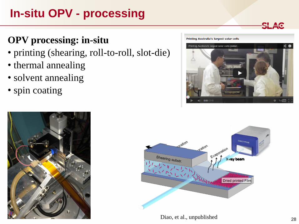
In-situ OPV - processing
28
OPV processing: in-situ
• printing (shearing, roll-to-roll, slot-die)
• thermal annealing
• solvent annealing
• spin coating
Diao, et al., unpublished
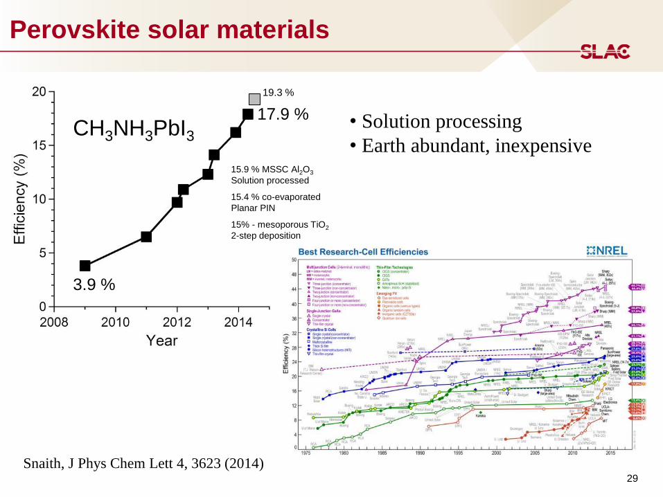
Perovskite solar materials
29
3.9 %
17.9 %
19.3 %
15% - mesoporous TiO2
2-step deposition
15.4 % co-evaporated
Planar PIN
15.9 % MSSC Al2O3
Solution processed
CH3NH3PbI3 • Solution processing
• Earth abundant, inexpensive
Snaith, J Phys Chem Lett 4, 3623 (2014)

30
Perovskite PV
CH3NH3PbI3: where’s the (organic) atoms + dynamics?
• orientation of CH3NH3+ (MA)
• dynamics of MA, I?
• films – 100s nm CH3NH3PbI3
XRD
start
2 hrs
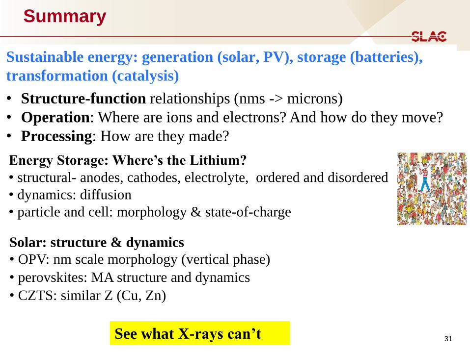
Summary
• Structure-function relationships (nms -> microns)
• Operation: Where are ions and electrons? And how do they move?
• Processing: How are they made?
Sustainable energy: generation (solar, PV), storage (batteries),
transformation (catalysis)
31
Energy Storage: Where’s the Lithium?
• structural- anodes, cathodes, electrolyte, ordered and disordered
• dynamics: diffusion
• particle and cell: morphology & state-of-charge
Solar: structure & dynamics
• OPV: nm scale morphology (vertical phase)
• perovskites: MA structure and dynamics
• CZTS: similar Z (Cu, Zn)
See what X-rays can’t

32
Thanks
• SSRL Materials Sciences & Technical Staff
o Johanna Nelson Weker, Chris Tassone
• Research Group (present and past)
o Linda Lim, Kristin Schmidt
• Cui & McGehee groups at Stanford


Battery Operation
34 34
Discharge Charge
Li+
Current collector (Cu foil)
Current collector (Al foil)
Composite electrode (Active powder/binder /conducting aids)
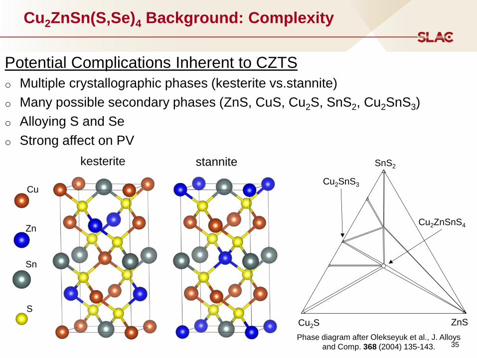
Cu2ZnSn(S,Se)4 Background: Complexity
Potential Complications Inherent to CZTS
o Multiple crystallographic phases (kesterite vs.stannite)
o Many possible secondary phases (ZnS, CuS, Cu2S, SnS2, Cu2SnS3)
o Alloying S and Se
o Strong affect on PV
kesterite stannite
Cu
Zn
Sn
S
35 Phase diagram after Olekseyuk et al., J. Alloys
and Comp. 368 (2004) 135-143.
Cu2S ZnS
SnS2
Cu2ZnSnS4
Cu2SnS3
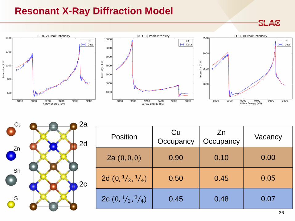
Resonant X-Ray Diffraction Model
Cu
Zn
Sn
S
2a
2d
2c
Position Cu
Occupancy
Zn
Occupancy Vacancy
0.90 0.10 0.00
0.50 0.45 0.05
0.45 0.48 0.07
36
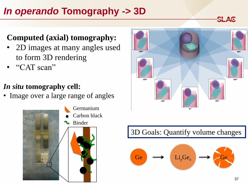
In operando Tomography -> 3D
37
In situ tomography cell:
• Image over a large range of angles
Germanium
Carbon black
Binder
LiyGex Ge Ge
Computed (axial) tomography:
• 2D images at many angles used
to form 3D rendering
• “CAT scan”
3D Goals: Quantify volume changes
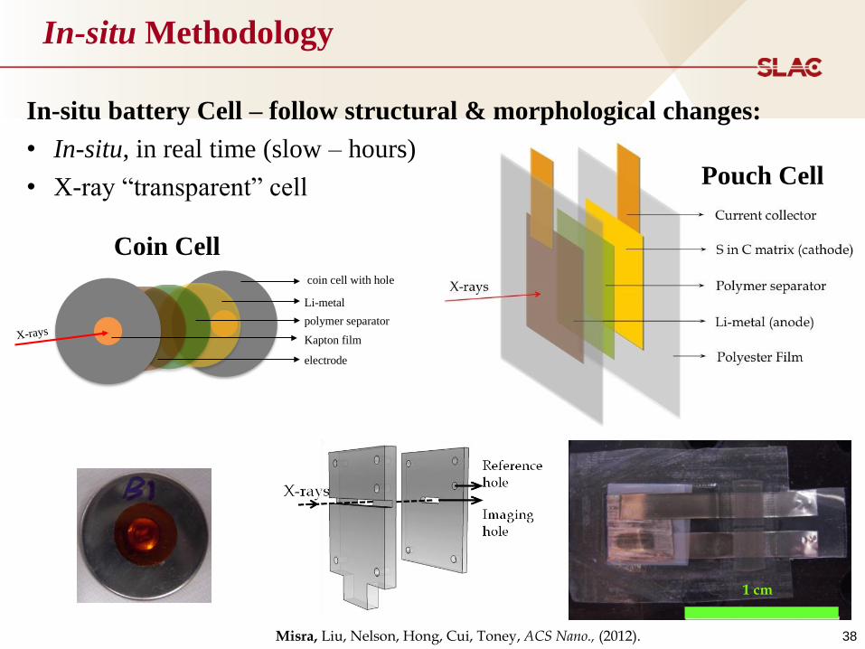
In-situ Methodology
38
X-ray Microscopy
In-situ battery Cell – follow structural & morphological changes:
• In-situ, in real time (slow – hours)
• X-ray “transparent” cell
Misra, Liu, Nelson, Hong, Cui, Toney, ACS Nano., (2012).
1 cm
coin cell with hole
electrode
Li-metal
Kapton film
polymer separator
X-rays
Coin Cell
Pouch Cell