neutron interferometry at a pulsed source
TRANSCRIPT
80
Neutron interferometry at a pulsed source
Nuclear Instruments and Methods in Physics Research A300 (1991) 80-84North-Holland
J. Kulda, P. Lukás and P. MikulaNuclear Physics Institute, Czechoslovak Academy of Sciences, 250 68 Rei near Prague, Czechoslovakia
Yu.A . Alexandrov, L.N. Sedláková and M. VránaLaboratory of Neutron Physics JINR Dubna, P.O Box 79, 101000 Moscow, USSR
H. RauchAtominstitut der Österreichischen Universitdten, Schüttelstrasse 115, A-1020 Wien, Austria
Received 20 August 1990
A compact setup providing vibration damping support as well as thermal shielding for a classical LLL interferometer wasdeveloped and installed at the IBR-2 pulsed reactor at JINR Dubna. Despite the low incident neutron flux successful experimentswere performed with two different LLL-type interferometer crystals and simultaneous observation of the interference patterns on tworeflection orders was demonstrated . This first experience leads to the conclusion that routine experiments m the multi-wavelengthregime are feasible, but a careful optimization of the setup regarding the opposing demands on TOF resolution, incident flux andbackground would be desirable to compensate at least partially for the rapid decrease of diffracted intensity at higher reflectionorders .
1. Introduction
Since its advent in mid 70's [1,2] neutron interferom-etry has become a well established tool both in funda-mental and nuclear physics. The experimental resultsobtained during the years by several groups includetests of fundamental statements of quantum mechanics(41T periodicity of spinors, principle of equivalence ingravity, cf . e.g . ref . [3]) on the one hand and highlyaccurate values of neutron scattenng lengths for a longlist of elements and their isotopes [4] on the other hand .All the experiments have been performed at stationarysources providing fluxes large enough to keep the mea-surement times within reasonable limits. Most of thescattering length measurements were done at the ILLGrenoble where a fixed wavelength (a = 2.0 ,4) is usedfor the greater part of the work .
Only few experiments dealt with the energy depen-dence of the neutron scattering lengths. In this connec-tion the low-lying resonance of 149Sm has been investi-gated by neutron interferometry methods [5,6] . Pulsedneutrons produced by a fast mechanical chopper havebeen used for testing the phase echo principle and thedispersiveness of a neutron bunch [7] . Up to now noexperiments have been done with polychromatic pulsedsources in the TOF regime where the main promiseconsists of the possibility to observe simultaneously the
0168-9002/91/$03 .50 U 1991 - Elsevier Science Publishers B.V . (North-Holland)
interference pattern at several orders of reflection onthe interferometer crystal . In this way information canbe obtained on scattering length variation with neutronenergy . This knowledge, as pointed out recently byLynn [8], becomes increasingly important with the useof new pulsed sources providing sufficiently high fluxesfor diffraction work in the epithermal range. The resultsobtained by multiple wavelength interferometry mayachieve high accuracy thanks to the direct determina-tion of the ratio of the two (or more) simultaneouslymeasured scattering lengths - a strategy already em-ployed with synchrotron radiation to determine disper-sion corrections to X-ray scattering lengths [9]. Thepresent article reports first steps aiming to fill this gapand paying attention mainly to the methodical aspectsof neutron interferometry at a pulsed source .
2. The DIFRAN setup
Our interferometers were installed on the double-axisspectrometer DIFRAN [10] at the pulsed reactor IBR-2at JINR, Dubna. This reactor operates at a repetitionrate of 5 cycles/s with a pulse width of about 280 lis .The flight path of the neutrons between the reactor coreand the instrument is 28 .5 m in an evacuated tube
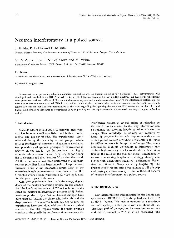
equipped with a set of collimators limiting the horizon-tal and vertical beam divergences to 7' and 15', respec-tively . The mean density of the thermal neutron flux atthe first axis of DIFRAN is 1 .9 X 10 6 n/(cm2 s) at anaverage power of 2 MW. Fig. 1 displays its spectraldistribution obtained from the vanadium scattering in-tensities corrected for absorption and multiple scatter-ing as well as a few points derived from the intensity ofa 400 symmetric Bragg reflection by a perfect Si plate of395 ltm thickness. Unlike the more recent spallationsources the IBR-2 flux spectrum exhibits a pronouncedMaxwellian component with a peak in the region of1 Á.
The incident beam is reflected by a bent perfect Simonochromator m a parallel (nondispersive) setting withrespect to the interferometer crystal . Its bending radiusR = 200 m provides an approximately rectangular re-flection curve of about 10" width and unit peak reflec-tivity [11] so that no losses in intensity occur. The 220reflection is used in both cases and the working wave-length A = 1 Á is defined with a relative uncertaintyAX/X = 7 x 10 -3 .
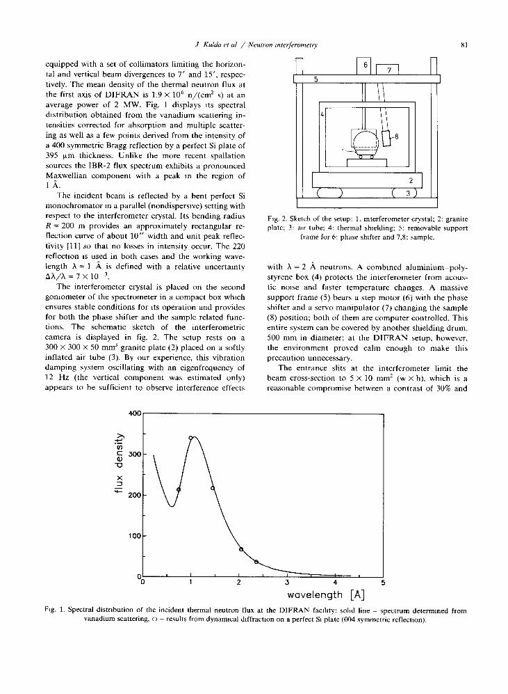
The interferometer crystal is placed on the secondgoniometer of the spectrometer in a compact box whichensures stable conditions for its operation and providesfor both the phase shifter and the sample related func-tions . The schematic sketch of the interferometriccamera is displayed in fig . 2. The setup rests on a300 X 300 x 50 mm3 granite plate (2) placed on a softlyinflated air tube (3) . By our experience, this vibrationdamping system oscillating with an eigenfrequency of12 Hz (the vertical component was estimated only)appears to be sufficient to observe interference effects
400
200
100
J Kulda et al / Neutron interferometry
Fig. 2 . Sketch of the setup : 1 . interferometer crystal ; 2 : graniteplate; 3 : air tube ; 4: thermal shielding ; 5 : removable support
frame for 6 : phase shifter and 7,8 : sample.
with A = 2 X neutrons . A combined aluminium-poly-styrene box (4) protects the interferometer from acous-tic noise and faster temperature changes. A massivesupport frame (5) bears a step motor (6) with the phaseshifter and a servo manipulator (7) changing the sample(8) position ; both of them are computer controlled . Thisentire system can be covered by another shielding drum,500 mm in diameter ; at the DIFRAN setup, however,the environment proved calm enough to make thisprecaution unnecessary .
The entrance slits at the interferometer limit thebeam cross-section to 5 x 10 mm2 (w X h), which is areasonable compromise between a contrast of 30% and
3
4
wavelength [A]
81
Fig . 1 . Spectral distribution of the incident thermal neutron flux at the DIFRAN facility : solid line - spectrum determined fromvanadium scattering, o - results from dynamical diffraction on a perfect Si plate (004 symmetric reflection) .
82
a minimum acceptable count rate of 0.25 cps in the Obeam which corresponds to approximately 1 neutronper 20 reactor bursts . The interfering neutron beams, Oand G, are detected by two 3He detectors of 90 mmdiameter with a massive Cd and borated polyethylenefront side shielding reducing the detector aperture tothe actual beam size. In this way the background can bekept as low as 0.05 cps.
3. Experimental results
The first part of the experiments was performed withan interferometer (reffered to as A) designed for low-wavelength work and manufactured at NPI kei [12]from zone-melted Si ingot of 2 in . diameter. The maxi-mum working wavelength was limited by its dimensionsto 1.3 f1 . With this crystal, when set to a= 1 .08 A, theinterference modulation was observed in the first-orderreflection 220 featuring a 30% contrast visibility at abeam cross section of 5 x 10 mm2. The higher reflectionorders, 440 etc., could, however, not be resolved fromthe background because of a rapid drop of their reflect-ing power. The integrated intensity diffracted by aperfect crystal illuminated by a white beam can bewritten according to ref . [13] as
N 1 Fhkl 1 X3Ihkl=Rnklio(Ä)so
21T sin2o
Hence, apart from the unimportant changes in thereduced dynamical reflectivity Rhk, (which oscillates
T
C(V41C
J. Kulda et aL / Neutron interferometry
about iT/2) and in the structure factor Fhkl " the inten-sity reflected by 440 drops compared to 220 by a factorof 8 due to the a/2 wavelength. Another factor ofabout 2 comes from the incident flux spectrum io(N)which has a minimum in the neighbourhood of 0.5 ?+(cf. fig. 1). At still higher orders this drop continues, butthe raise of the epithermal component of co(A) com-pensates it to some extent .
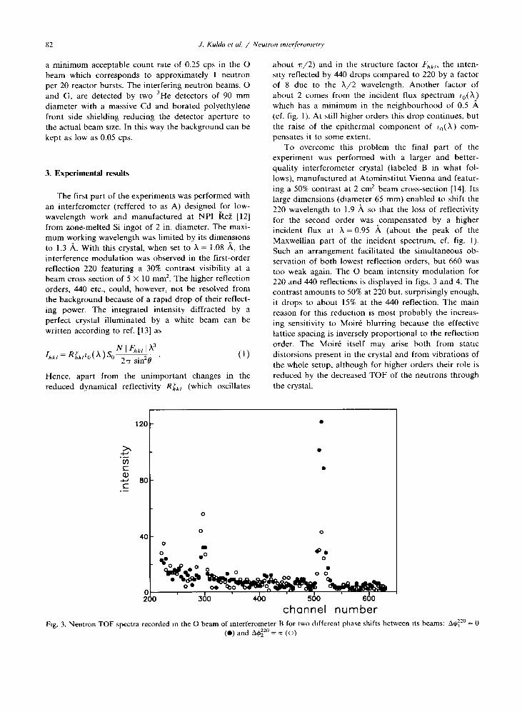
To overcome this problem the final part of theexperiment was performed with a larger and better-quality interferometer crystal (labeled B in what fol-lows), manufactured at Atominstitut Vienna and featur-ing a 50% contrast at 2 cm2 beam cross-section [14] . Itslarge dimensions (diameter 65 mm) enabled to shift the220 wavelength to 1.9 A so that the loss of reflectivityfor the second order was compensated by a higherincident flux at X = 0.95 Á (about the peak of theMaxwellian part of the incident spectrum, cf . fig . 1) .Such an arrangement facilitated the simultaneous ob-servation of both lowest reflection orders, but 660 wastoo weak again. The O beam intensity modulation for220 and 440 reflections is displayed in figs . 3 and 4. Thecontrast amounts to 50% at 220 but, surprisingly enough,it drops to about 15% at the 440 reflection . The mainreason for this reduction is most probably the increas-ing sensitivity to Moiré blurring because the effectivelattice spacing is inversely proportional to the reflectionorder. The Moiré itself may arise both from staticdistorsions present in the crystal and from vibrations ofthe whole setup, although for higher orders their role isreduced by the decreased TOF of the neutrons throughthe crystal .
Fig . 3 . Neutron TOF spectra recorded m the O beam of interferometer B for two different phase shifts between its beams: 00220 =0(") and A~22° _
(o)
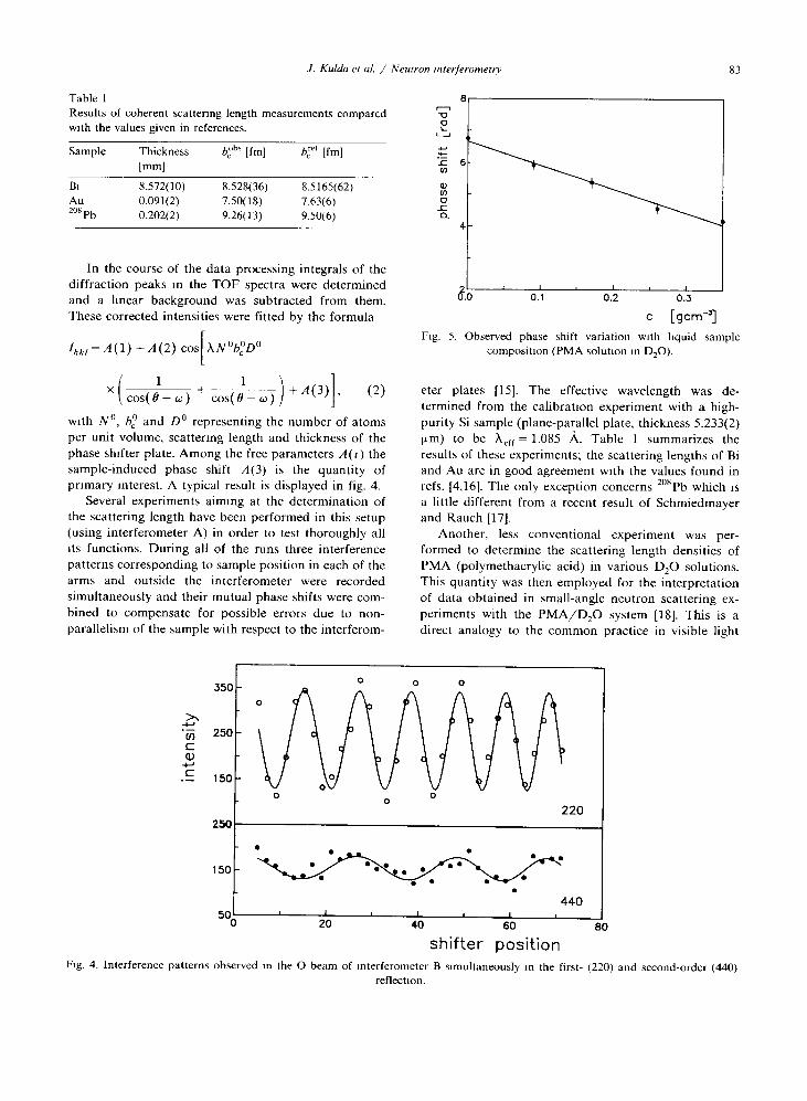
Table 1Results of coherent scattering length measurements comparedwith the values given in references .
Sample
Thickness
b° hs [fm]
b,"t [fm][mm]
Bi 8.572(10) 8.528(36) 8.5165(62)Au 0.09l(2) 7.50(l8) 7.63(6)208Pb 0.202(2) 9.26(13) 9.50(6)
In the course of the data processing integrals of thediffraction peaks m the TOF spectra were determinedand a linear background was subtracted from them .These corrected intensities were fitted by the formula
Intit =A(1) +A(2) cost XN°b°D°
1
1
() ()X(cos(6+w)+cos(0-w))+A 31
2
with N°, b° and D° representing the number of atomsper unit volume, scattering length and thickness of thephase shifter plate . Among the free parameters A(i) thesample-induced phase shift A(3) is the quantity ofprimary interest . A typical result is displayed in fig . 4.
Several experiments aiming at the determination ofthe scattering length have been performed in this setup(using interferometer A) in order to test thoroughly allits functions . During all of the runs three interferencepatterns corresponding to sample position in each of thearms and outside the interferometer were recordedsimultaneously and their mutual phase shifts were com-bined to compensate for possible errors due to non-parallelism of the sample with respect to the interferom-
"tAC
C
350
250
150
250
150
J. Kulda et al. / Neutron interferometry
8v0
L
a0rC1-
Fig. 5. Observed phase shift variation with liquid samplecomposition (PMA solution in Dz0).
eter plates [15] . The effective wavelength was de-termined from the calibration experiment with a high-purity Si sample (plane-parallel plate, thickness 5.233(2)Win) to be kfr = 1.085 Á. Table 1 summarizes theresults of these experiments ; the scattering lengths of Biand Au are in good agreement with the values found inrefs . [4,16] . The only exception concerns 208Pb which isa little different from a recent result of Schmiedmayerand Rauch [17] .
Another, less conventional experiment was per-formed to determine the scattering length densities ofPMA (polymethacrylic acid) in various Dz0 solutions.This quantity was then employed for the interpretationof data obtained in small-angle neutron scattering ex-periments with the PMA/D20 system [18] . This is adirect analogy to the common practice in visible light
D
220
440
40
60shifter position
80
c [gcm'1
83
Fig . 4 . Interference patterns observed m the O beam of interferometer B simultaneously m the first- (220) and second-order (440)reflection .
84
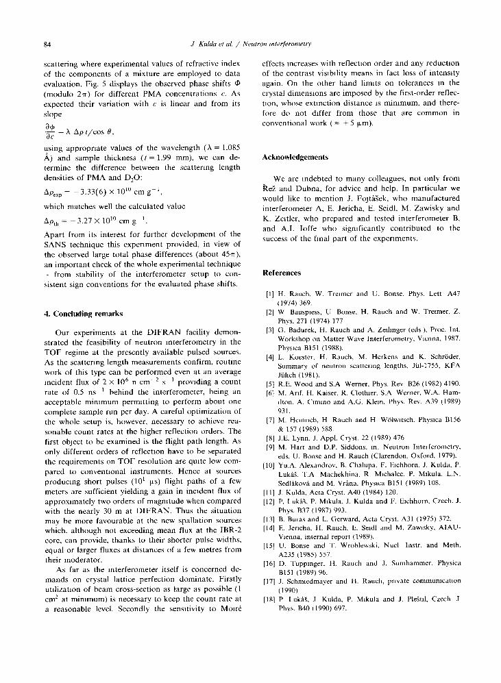
scattering where experimental values of refractive index
of the components of a mixture are employed to data
evaluation . Fig. 5 displays the observed phase shifts 0
(modulo 2m) for different PMA concentrations c. As
expected their variation with c is linear and from its
slope
a c= À Op t/cos 0,á
using appropriate values of the wavelength (X = 1 .085
Pi) and sample thickness (t= 1.99 mm), we can de-
termine the difference between the scattering lengthdensities of PMA and D20:
Opexp = -3 .33(6) x 10'° cm g-',
which matches well the calculated value
Op, = -3 .27x10' ° cmg- ' .
Apart from its interest for further development of the
SANS technique this experiment provided, in view of
the observed large total phase differences (about 45m),
an important check of the whole experimental technique
- from stability of the interferometer setup to con-
sistent sign conventions for the evaluated phase shifts .
4. Concluding remarks
Our experiments at the DIFRAN facility demon-strated the feasibility of neutron interferometry in the
TOF regime at the presently available pulsed sources.
As the scattering length measurements confirm, routine
work of this type can be performed even at an average
incident flux of 2 x 10⁶ n cm-2 s- ' providing a count
rate of 0.5 ns- ' behind the interferometer, being an
acceptable minimum permitting to perform about one
complete sample run per day. A careful optimization of
the whole setup is, however, necessary to achieve rea-sonable count rates at the higher reflection orders . The
first object to be examined is the flight path length . As
only different orders of reflection have to be separated
the requirements on TOF resolution are quite low com-
pared to conventional instruments. Hence at sources
producing short pulses (10' ws) flight paths of a few
meters are sufficient yielding a gain in incident flux of
approximately two orders of magnitude when comparedwith the nearly 30 m at DIFRAN. Thus the situationmay be more favourable at the new spallation sources
which, although not exceeding mean flux at the IBR-2
core, can provide, thanks to their shorter pulse widths,equal or larger fluxes at distances of a few metres from
their moderator.As far as the interferometer itself is concerned de-
mands on crystal lattice perfection dominate . Firstlyutilization of beam cross-section as large as possible (1cm2 at minimum) is necessary to keep the count rate at
a reasonable level. Secondly the sensitivity to Moiré
J Kulda et aL / Neutron interjerometry
effects increases with reflection order and any reductionof the contrast visibility means in fact loss of intensity
again. On the other hand limits on tolerances m the
crystal dimensions are imposed by the first-order reflec-
tion, whose extinction distance is minimum, and there-
fore do not differ from those that are common in
conventional work (= ±5
Acknowledgements
We are indebted to many colleagues, not only fromkez and Dubna, for advice and help . In particular we
would like to mention J. Fcjtásek, who manufacturedinterferometer A, E. Jericha, E. Seidl, M. Zawisky andK. Zeitler, who prepared and tested interferometer B,and A.I . Ioffe who significantly contributed to thesuccess of the final part of the experiments.
References
[1] H. Rauch, W. Treimer and U . Bonse, Phys . Lett A47(1974) 369.
[2] W Bauspiess, U Bonse, H. Rauch and W. Treimer, Z.Phys . 271 (1974) 177
[3] G. Badurek, H. Rauch and A. Zeilenger (eds ), Proc . Int.Workshop on Matter Wave Interferometry, Vienna, 1987,Physica B151 (1988) .
[4] L. Koester, H. Rauch, M. Herkens and K. Schrbder,Summary of neutron scattering lengths, Jù1-1755, KFAJülich (1981) .
[5] R.E. Wood and S.A Werner, Phys . Rev B26 (1982) 4190.[6] M. Anf, H. Kaiser, R. Clothier, S.A Werner, W.A . Ham-
ilton, A. Cimmo and A.G. Klein, Phys. Rev. A39 (1989)931 .M. Heinrich, H Rauch and H Wblwitsch, Physica B156& 157 (1989) 588.J.E . Lynn, J. Appl . Cryst. 22 (1989) 476M. Hart and D.P . Siddons, m. Neutron Interferometry,eds. U. Bonse and H. Rauch (Clarendon, Oxford, 1979).
[10] Yu.A . Alexandrov, B. Chalupa, F. Eichhorn, J. Kulda, P.Lukás, T.A Machekhina, R. Michalec, P. Mikula, L.N .Sedláková and M. Vrána, Physica B151 (1989) 108.
[11] J. Kulda, Acta Cryst. A40 (1984) 120.[12] P. Lukás, P. Mikula, J. Kulda and F. Eichhorn, Czech. J.
Phys. B37 (1987) 993.[13] B. Buras and L. Gerward, Acta Cryst. A31 (1975) 372.[14] E. Jericha, H . Rauch, E. Seidl and M. Zawisky, AIAU-
Vienna, internal report (1989).[15] U. Bonse and T. Wroblewski, Nucl Instr. and Meth .
A235 (1985) 557.[16] D. Tuppmger, H. Rauch and J. Sumhammer, Physica
B151 (1989) 96 .[17] J. Schmiedmayer and H . Rauch, private communication
(1990)[181 P LukM, J Kulda, P. Mikula and J . Plestil, Czech. J
Phys . B40 (1990) 697.
[8][9]
[Lm) .