networkhd™habitech.s3.amazonaws.com/pdfs/wyr/wyr-nhd-400-tx... · nhd-sw-0501...
TRANSCRIPT
Thank you for choosing this WyreStorm product. Please read these instructions carefully before installing to avoid complications later.
Copyright © 2017 WyreStorm Technologies | wyrestorm.com
NetworkHD™ 100 | 200 | 400 Series Components
Installation Guide Document Revision: v2.1
Document Date: November 7th 2017
Supported Firmware: v2.0.0 or higher

NetworkHD 100/200/400 Series Installation Guide | Copyright © 2017 WyreStorm Technologies | wyrestorm.com 2 of 37
IMPORTANT! Safety Information
Safety Classifications Note: Provides special information for installing, configuring, and operating the
equipment.
IMPORTANT! Provides special information that is critical to installing, configuring, and operating the equipment.
CAUTION! Provides special information on avoiding situations that may cause damage to equipment.
WARNING! Provides special information on avoiding situations that may cause physical danger to the installer, end user, etc.
ELECTRIC SHOCK! The source power poses an electric shock hazard that has the potential to cause serious injury to installers and end users.
ELECTRICAL DISCONNECT:
The source power outlet and power supply input power sockets should be easily accessible to disconnect power in the event of an electrical hazard or malfunction.
WEIGHT INJURY! Installing some of the equipment requires two installers to ensure safe handling during installation. Failure to use two installers may result in injury.
Safety Statements 1. Read these instructions in their entirety and retain a copy for later reference.
2. Follow all instructions and heed all warnings.
3. Do not expose this apparatus to rain, moisture, sprays, drips or splashes and ensure that no objects containing liquids are placed on the apparatus, including cups, glasses and vases.
4. Do not place this unit in a confined space such as enclosed shelving, cabinets or bookshelves. Ensure the unit is adequately ventilated.
5. To prevent the risk of electric shock or fire hazard due to overheating, do not cover the unit or obstruct ventilation openings with material, newspaper, cardboard or anything that may restrict airflow into the unit.
6. Do not install near external heat sources such as radiators, heat registers, boilers or any device that produces heat such as amplifiers or computers and do not place near sources of naked flame.
7. Unplug apparatus from power supply during lightning storms or when unused for long periods of time.
8. Protect the power cable from being walked on, pinched or restricted in any way, especially at plug connections.
9. Only use attachments/accessories specified by the manufacturer.
10. Units contain non-serviceable parts - Refer all servicing to qualified service personnel.
IMPORTANT! Do Not Hot swap HDMI or LAN connections - Please insert and extract cables carefully with the power SWITCHED OFF. Power is passed along transmissions so connecting and disconnecting cables while powered can result in damage to circuitry or possible injury.
NetworkHD 100/200/400 Series Installation Guide | Copyright © 2017 WyreStorm Technologies | wyrestorm.com 3 of 37
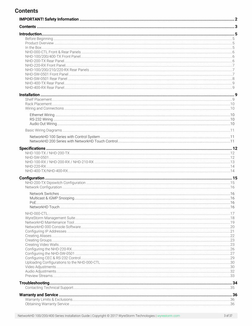
Contents IMPORTANT! Safety Information ...................................................................................................................................... 2
Contents ........................................................................................................................................................................... 3
Introduction....................................................................................................................................................................... 5 Before Beginning ..................................................................................................................................................................................................... 5 Product Overview .................................................................................................................................................................................................... 5 In the Box .................................................................................................................................................................................................................. 5 NHD-000-CTL Front & Rear Panels ...................................................................................................................................................................... 6 NHD-100/200/400-TX Front Panel ....................................................................................................................................................................... 6 NHD-200-TX Rear Panel ......................................................................................................................................................................................... 6 NHD-220-RX Front Panel........................................................................................................................................................................................ 7 NHD-100/200/210/220-RX Rear Panels ............................................................................................................................................................. 7 NHD-SW-0501 Front Panel .................................................................................................................................................................................... 7 NHD-SW-0501 Rear Panel ..................................................................................................................................................................................... 8 NHD-400-TX Rear Panel ......................................................................................................................................................................................... 9 NHD-400-RX Rear Panel ......................................................................................................................................................................................... 9
Installation ........................................................................................................................................................................ 9 Shelf Placement....................................................................................................................................................................................................... 9 Rack Placement .....................................................................................................................................................................................................10 Wiring and Connections .......................................................................................................................................................................................10
Ethernet Wiring .................................................................................................................................................................................................10 RS-232 Wiring ...................................................................................................................................................................................................10 Audio Out Wiring ...............................................................................................................................................................................................10
Basic Wiring Diagrams .........................................................................................................................................................................................11 NetworkHD 100 Series with Control System ...............................................................................................................................................11 NetworkHD 200 Series with NetworkHD Touch Control ............................................................................................................................11
Specifications ................................................................................................................................................................. 12 NHD-100-TX / NHD-200-TX .................................................................................................................................................................................12 NHD-SW-0501 ........................................................................................................................................................................................................12 NHD-100-RX / NHD-200-RX / NHD-210-RX ......................................................................................................................................................13 NHD-220-RX ...........................................................................................................................................................................................................14 NHD-400-TX/NHD-400-RX ...................................................................................................................................................................................14
Configuration .................................................................................................................................................................. 15 NHD-200-TX Dipswitch Configuration ...............................................................................................................................................................15 Network Configuration .........................................................................................................................................................................................16
Network Switches ............................................................................................................................................................................................16 Multicast & IGMP Snooping ............................................................................................................................................................................16 PoE ......................................................................................................................................................................................................................16 NetworkHD Touch ............................................................................................................................................................................................16
NHD-000-CTL .........................................................................................................................................................................................................17 WyreStorm Management Suite ...........................................................................................................................................................................18 NetworkHD Maintenance Tool ............................................................................................................................................................................19 NetworkHD 000 Console Software.....................................................................................................................................................................20 Configuring IP Addresses ....................................................................................................................................................................................21 Creating Aliases .....................................................................................................................................................................................................22 Creating Groups .....................................................................................................................................................................................................23 Creating Video Walls .............................................................................................................................................................................................23 Configuring the NHD-220-RX...............................................................................................................................................................................26 Configuring the NHD-SW-0501 ...........................................................................................................................................................................27 Configuring CEC & RS-232 Control .....................................................................................................................................................................29 Uploading Configurations to the NHD-000-CTL ...............................................................................................................................................30 Video Adjustments ................................................................................................................................................................................................30 Audio Adjustments ................................................................................................................................................................................................32 Preview Streams....................................................................................................................................................................................................33
Troubleshooting .............................................................................................................................................................. 34 Contacting Technical Support .............................................................................................................................................................................35
Warranty and Service ...................................................................................................................................................... 36 Warranty Limits & Exclusions ..............................................................................................................................................................................36 Obtaining Warranty Service .................................................................................................................................................................................36

NetworkHD 100/200/400 Series Installation Guide | Copyright © 2017 WyreStorm Technologies | wyrestorm.com 4 of 37
Publication Disclaimer .................................................................................................................................................... 37
NetworkHD 100/200/400 Series Installation Guide | Copyright © 2017 WyreStorm Technologies | wyrestorm.com 5 of 37
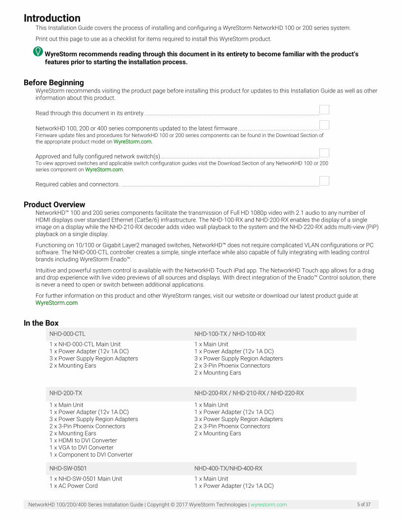
Introduction This Installation Guide covers the process of installing and configuring a WyreStorm NetworkHD 100 or 200 series system.
Print out this page to use as a checklist for items required to install this WyreStorm product.
WyreStorm recommends reading through this document in its entirety to become familiar with the product’s features prior to starting the installation process.
Before Beginning WyreStorm recommends visiting the product page before installing this product for updates to this Installation Guide as well as other information about this product.
Read through this document in its entirety. ....................................................................................................................................
NetworkHD 100, 200 or 400 series components updated to the latest firmware .............................................................. Firmware update files and procedures for NetworkHD 100 or 200 series components can be found in the Download Section of the appropriate product model on WyreStorm.com.
Approved and fully configured network switch(s) ......................................................................................................................... To view approved switches and applicable switch configuration guides visit the Download Section of any NetworkHD 100 or 200 series component on WyreStorm.com.
Required cables and connectors. .......................................................................................................................................................
Product Overview NetworkHD™ 100 and 200 series components facilitate the transmission of Full HD 1080p video with 2.1 audio to any number of HDMI displays over standard Ethernet (Cat5e/6) infrastructure. The NHD-100-RX and NHD-200-RX enables the display of a single image on a display while the NHD-210-RX decoder adds video wall playback to the system and the NHD-220-RX adds multi-view (PiP) playback on a single display.
Functioning on 10/100 or Gigabit Layer2 managed switches, NetworkHD™ does not require complicated VLAN configurations or PC software. The NHD-000-CTL controller creates a simple, single interface while also capable of fully integrating with leading control brands including WyreStorm Enado™.
Intuitive and powerful system control is available with the NetworkHD Touch iPad app. The NetworkHD Touch app allows for a drag and drop experience with live video previews of all sources and displays. With direct integration of the Enado™ Control solution, there is never a need to open or switch between additional applications.
For further information on this product and other WyreStorm ranges, visit our website or download our latest product guide at WyreStorm.com
In the Box NHD-000-CTL NHD-100-TX / NHD-100-RX
1 x NHD-000-CTL Main Unit 1 x Power Adapter (12v 1A DC) 3 x Power Supply Region Adapters 2 x Mounting Ears
1 x Main Unit 1 x Power Adapter (12v 1A DC) 3 x Power Supply Region Adapters 2 x 3-Pin Phoenix Connectors 2 x Mounting Ears
NHD-200-TX NHD-200-RX / NHD-210-RX / NHD-220-RX
1 x Main Unit 1 x Power Adapter (12v 1A DC) 3 x Power Supply Region Adapters 2 x 3-Pin Phoenix Connectors 2 x Mounting Ears 1 x HDMI to DVI Converter 1 x VGA to DVI Converter 1 x Component to DVI Converter
1 x Main Unit 1 x Power Adapter (12v 1A DC) 3 x Power Supply Region Adapters 2 x 3-Pin Phoenix Connectors 2 x Mounting Ears
NHD-SW-0501 NHD-400-TX/NHD-400-RX
1 x NHD-SW-0501 Main Unit 1 x AC Power Cord
1 x Main Unit 1 x Power Adapter (12v 1A DC)
NetworkHD 100/200/400 Series Installation Guide | Copyright © 2017 WyreStorm Technologies | wyrestorm.com 6 of 37
1 x 11-Pin Phoenix Connector 2 x 4-Pin Phoenix Connector 2 x 3-Pin Phoenix Connector 2 x Mounting Brackets
3 x Power Supply Region Adapters 2 x Mounting Brackets 1 x 3-Pin Phoenix Connector (RX only) 1 x IR Emitting Cable 1 x IR Receiving Cable
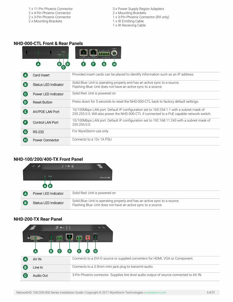
NHD-000-CTL Front & Rear Panels
Card Insert Provided insert cards can be placed to identify information such as an IP address.
Status LED Indicator Solid Blue: Unit is operating properly and has an active sync to a source. Flashing Blue: Unit does not have an active sync to a source.
Power LED Indicator Solid Red: Unit is powered on
Reset Button Press down for 5 seconds to reset the NHD-000-CTL back to factory default settings.
AV/POE LAN Port 10/100Mbps LAN port. Default IP configuration set to 169.254.1.1 with a subnet mask of 255.255.0.0. Will also power the NHD-000-CTL if connected to a PoE capable network switch.
Control LAN Port 10/100Mbps LAN port. Default IP configuration set to 192.168.11.243 with a subnet mask of 255.255.0.0.
RS-232 For WyreStorm use only.
Power Connector Connects to a 12v 1A PSU.
NHD-100/200/400-TX Front Panel
Power LED Indicator Solid Red: Unit is powered on
Status LED Indicator Solid Blue: Unit is operating properly and has an active sync to a source. Flashing Blue: Unit does not have an active sync to a source.
NHD-200-TX Rear Panel
AV IN Connects to a DVI-D source or supplied converters for HDMI, VGA or Component.
Line In Connects to a 3.5mm mini jack plug to transmit audio.
Audio Out 3-Pin Phoenix connector. Supplies line level audio output of source connected to AV IN.

NetworkHD 100/200/400 Series Installation Guide | Copyright © 2017 WyreStorm Technologies | wyrestorm.com 7 of 37
Ethernet Port PoE 10/100Mbps LAN port
RS-232 Output 3-Pin Phoenix connector. Connects to third party devices for RS-232 control.
3 Dipswitch Selector Configures the AV IN format. Dipswitch configuration information can be found on the underside of the unit.
Power Connector Connects to a 12v 1A PSU.
NHD-220-RX Front Panel
Power LED Indicator Solid Red: Unit is powered on.
Status LED Indicator Solid Blue: Unit is operating properly and has an active sync to a source. Flashing Blue: Unit does not have an active sync to a source.
ID Button When pressed OSD (On Screen Display) information such as IP address, Remote and Local hostnames.
NHD-100/200/210/220-RX Rear Panels
Grounding Screw Can be used to ground the decoder chassis.
Power Connector Connects to a 12V 1A PSU.
Ethernet Port PoE 10/100Mbps LAN port
HDMI Output 19-Pin type A HDMI female digital video/audio output.
Audio Out 3-Pin Phoenix connector. Supplies line level audio output of source connected to AV IN.
RS-232 Debug Port 3-Pin Phoenix connector. For WyreStorm use only.
RS-232 Output Port 3-Pin Phoenix connector. Connects to third party devices for RS-232 control.
NHD-SW-0501 Front Panel
NetworkHD 100/200/400 Series Installation Guide | Copyright © 2017 WyreStorm Technologies | wyrestorm.com 8 of 37
Mic Gain Adjusts the gain of the Mic Input from 0 to 40db.
HDMI Input 1-4 Selection Press to select and HDMI input as the active source. An illuminated LED indicates the currently HDMI source.
VGA Input Selection Press to select VGA input as the active source. An illuminated LED indicates the currently selected source is VGA>
Status LED Indicator Solid Blue: Unit is operating properly and has an active sync to a source. Flashing Blue: Unit does not have an active sync to a source.
Power LED Indicator Solid Red: Unit is powered on.
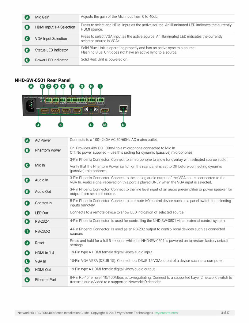
NHD-SW-0501 Rear Panel
AC Power Connects to a 100~240V AC 50/60Hz AC mains outlet.
Phantom Power On: Provides 48V DC 100mA to a microphone connected to Mic In Off: No power supplied – use this setting for dynamic (passive) microphones.
Mic In 3-Pin Phoenix Connector. Connect to a microphone to allow for overlay with selected source audio.
Verify that the Phantom Power switch on the rear panel is set to Off before connecting dynamic (passive) microphones.
Audio In 3-Pin Phoenix Connector. Connect to the analog audio output of the VGA source connected to the VGA In. Audio signal received on this port is played ONLY when the VGA input is selected.
Audio Out 3-Pin Phoenix Connector. Connect to the line level input of an audio pre-amplifier or power speaker for output from selected source.
Contact In 5-Pin Phoenix Connector. Connect to a remote I/O control device such as a panel switch for selecting inputs remotely.
LED Out Connects to a remote device to show LED indication of selected source.
RS-232-1 4-Pin Phoenix Connector. Is used for controlling the NHD-SW-0501 via an external control system.
RS-232-2 4-Pin Phoenix Connector. Is used as an RS-232 output to control local devices such as connected sources.
Reset Press and hold for a full 5 seconds while the NHD-SW-0501 is powered on to restore factory default settings.
HDMI In 1-4 19-Pin type A HDMI female digital video/audio input.
VGA In 15-Pin VGA VESA (DSUB 15). Connect to a DSUB 15 VGA output of a device such as a computer.
HDMI Out 19-Pin type A HDMI female digital video/audio output.
Ethernet Port 8-Pin RJ-45 female | 10/100Mbps auto-negotiating. Connect to a supported Layer 2 network switch to transmit audio/video to a supported NetworkHD decoder.
NetworkHD 100/200/400 Series Installation Guide | Copyright © 2017 WyreStorm Technologies | wyrestorm.com 9 of 37
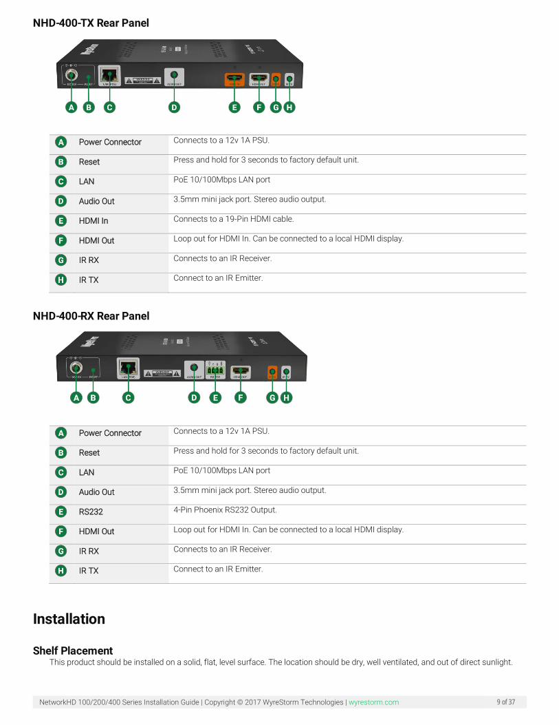
NHD-400-TX Rear Panel
Power Connector Connects to a 12v 1A PSU.
Reset Press and hold for 3 seconds to factory default unit.
LAN PoE 10/100Mbps LAN port
Audio Out 3.5mm mini jack port. Stereo audio output.
HDMI In Connects to a 19-Pin HDMI cable.
HDMI Out Loop out for HDMI In. Can be connected to a local HDMI display.
IR RX Connects to an IR Receiver.
IR TX Connect to an IR Emitter.
NHD-400-RX Rear Panel
Power Connector Connects to a 12v 1A PSU.
Reset Press and hold for 3 seconds to factory default unit.
LAN PoE 10/100Mbps LAN port
Audio Out 3.5mm mini jack port. Stereo audio output.
RS232 4-Pin Phoenix RS232 Output.
HDMI Out Loop out for HDMI In. Can be connected to a local HDMI display.
IR RX Connects to an IR Receiver.
IR TX Connect to an IR Emitter.
Installation
Shelf Placement This product should be installed on a solid, flat, level surface. The location should be dry, well ventilated, and out of direct sunlight.
NetworkHD 100/200/400 Series Installation Guide | Copyright © 2017 WyreStorm Technologies | wyrestorm.com 10 of 37
It is not acceptable to stack multiple products one atop of the other without a ventilation space between the units. WyreStorm recommends that if using more than two of this product, an empty space at least 1 rack unit (1.75 in) in height is used between every 2 chassis. This will assist in heat dissipation and prevent overheating.
Rack Placement Mounting ears are included with these products for installation on a solid flat surface. For NetworkHD decoders these mounting ears are typically used for mounting behind a display. If mounting a unit behind a display or in an enclosed area, ensure that the top and bottom vents are not obstructed.
NetworkHD 100 or 200 series encoders can be installed into the NHD-000-RACK. The NHD-000-RACK can hold up to 12 encoders and should be installed into a 19-inch equipment rack with at least 5RU of available space.
Note: The NHD-000-RACK is not included with NetworkHD components.
Wiring and Connections • WyreStorm recommends that all wiring for the installation is run and terminated prior to making connections to the product.
• Read through this section in this entirety before running or terminating the wires to ensure proper operation and to avoid damaging equipment
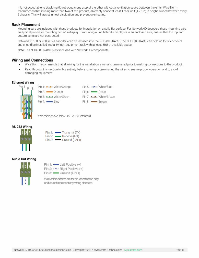
Ethernet Wiring
RS-232 Wiring
Audio Out Wiring

NetworkHD 100/200/400 Series Installation Guide | Copyright © 2017 WyreStorm Technologies | wyrestorm.com 11 of 37
Basic Wiring Diagrams
NetworkHD 100 Series with Control System
NetworkHD 200 Series with NetworkHD Touch Control
NetworkHD 100/200/400 Series Installation Guide | Copyright © 2017 WyreStorm Technologies | wyrestorm.com 12 of 37
Specifications
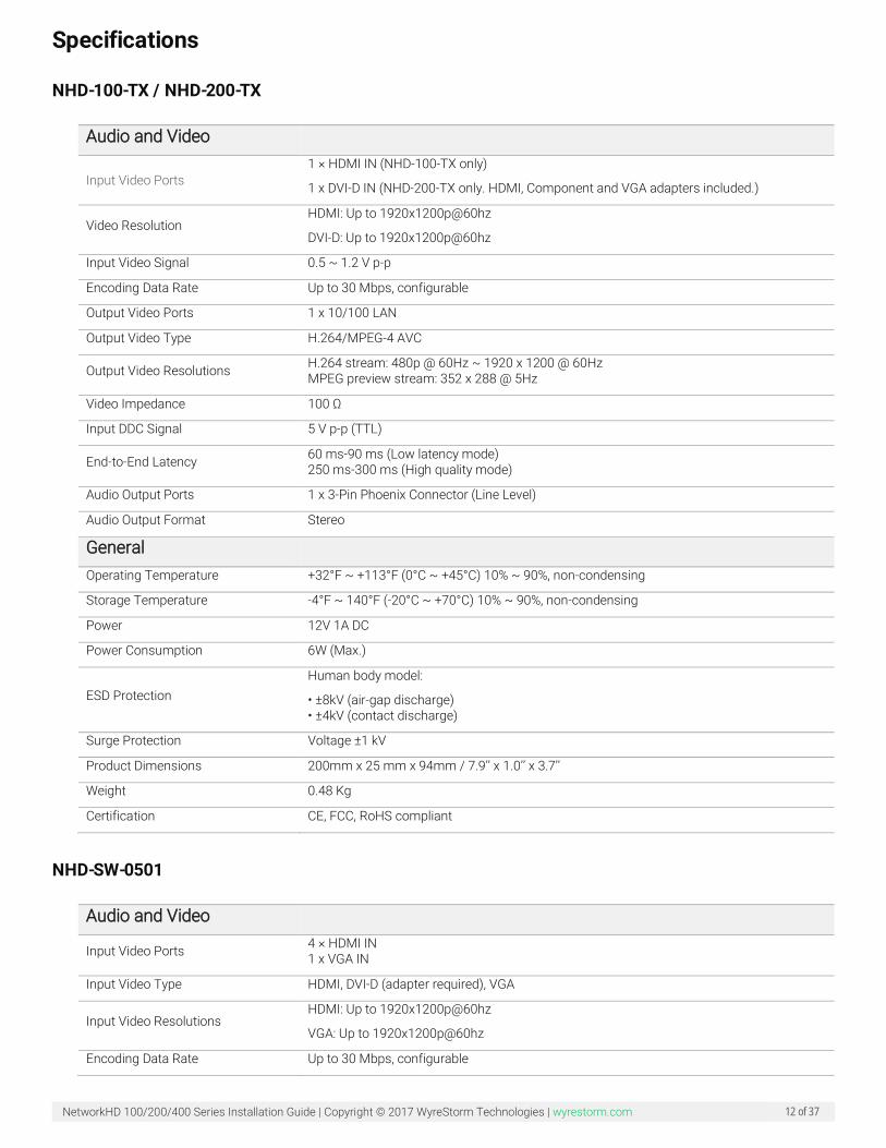
NHD-100-TX / NHD-200-TX
Audio and Video
Input Video Ports 1 × HDMI IN (NHD-100-TX only)
1 x DVI-D IN (NHD-200-TX only. HDMI, Component and VGA adapters included.)
Video Resolution HDMI: Up to 1920x1200p@60hz
DVI-D: Up to 1920x1200p@60hz
Input Video Signal 0.5 ~ 1.2 V p-p
Encoding Data Rate Up to 30 Mbps, configurable
Output Video Ports 1 x 10/100 LAN
Output Video Type H.264/MPEG-4 AVC
Output Video Resolutions H.264 stream: 480p @ 60Hz ~ 1920 x 1200 @ 60Hz MPEG preview stream: 352 x 288 @ 5Hz
Video Impedance 100 Ω
Input DDC Signal 5 V p-p (TTL)
End-to-End Latency 60 ms-90 ms (Low latency mode) 250 ms-300 ms (High quality mode)
Audio Output Ports 1 x 3-Pin Phoenix Connector (Line Level)
Audio Output Format Stereo
General
Operating Temperature +32°F ~ +113°F (0°C ~ +45°C) 10% ~ 90%, non-condensing
Storage Temperature -4°F ~ 140°F (-20°C ~ +70°C) 10% ~ 90%, non-condensing
Power 12V 1A DC
Power Consumption 6W (Max.)
ESD Protection Human body model:
• ±8kV (air-gap discharge) • ±4kV (contact discharge)
Surge Protection Voltage ±1 kV
Product Dimensions 200mm x 25 mm x 94mm / 7.9’’ x 1.0’’ x 3.7’’
Weight 0.48 Kg
Certification CE, FCC, RoHS compliant
NHD-SW-0501
Audio and Video
Input Video Ports 4 × HDMI IN 1 x VGA IN
Input Video Type HDMI, DVI-D (adapter required), VGA
Input Video Resolutions HDMI: Up to 1920x1200p@60hz
VGA: Up to 1920x1200p@60hz
Encoding Data Rate Up to 30 Mbps, configurable
NetworkHD 100/200/400 Series Installation Guide | Copyright © 2017 WyreStorm Technologies | wyrestorm.com 13 of 37
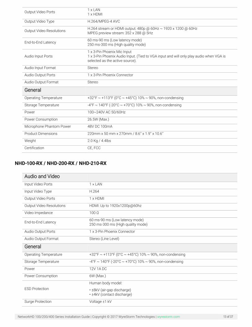
Output Video Ports 1 x LAN 1 x HDMI
Output Video Type H.264/MPEG-4 AVC
Output Video Resolutions H.264 stream or HDMI output: 480p @ 60Hz ~ 1920 x 1200 @ 60Hz MPEG preview stream: 352 x 288 @ 5Hz
End-to-End Latency 60 ms-90 ms (Low latency mode) 250 ms-300 ms (High quality mode)
Audio Input Ports 1 x 3-Pin Phoenix Mic Input 1 x 3-Pin Phoenix Audio Input. (Tied to VGA input and will only play audio when VGA is selected as the active source).
Audio Input Format Stereo
Audio Output Ports 1 x 3-Pin Phoenix Connector
Audio Output Format Stereo
General
Operating Temperature +32°F ~ +113°F (0°C ~ +45°C) 10% ~ 90%, non-condensing
Storage Temperature -4°F ~ 140°F (-20°C ~ +70°C) 10% ~ 90%, non-condensing
Power 100~240V AC 50/60Hz
Power Consumption 26.5W (Max.)
Microphone Phantom Power 48V DC 100mA
Product Dimensions 220mm x 50 mm x 270mm / 8.6’’ x 1.9’’ x 10.6’’
Weight 2.0 Kg / 4.4lbs
Certification CE, FCC
NHD-100-RX / NHD-200-RX / NHD-210-RX
Audio and Video
Input Video Ports 1 × LAN
Input Video Type H.264
Output Video Ports 1 x HDMI
Output Video Resolutions HDMI: Up to 1920x1200p@60hz
Video Impedance 100 Ω
End-to-End Latency 60 ms-90 ms (Low latency mode) 250 ms-300 ms (High quality mode)
Audio Output Ports 1 x 3-Pin Phoenix Connector
Audio Output Format Stereo (Line Level)
General
Operating Temperature +32°F ~ +113°F (0°C ~ +45°C) 10% ~ 90%, non-condensing
Storage Temperature -4°F ~ 140°F (-20°C ~ +70°C) 10% ~ 90%, non-condensing
Power 12V 1A DC
Power Consumption 6W (Max.)
ESD Protection Human body model:
• ±8kV (air-gap discharge) • ±4kV (contact discharge)
Surge Protection Voltage ±1 kV

NetworkHD 100/200/400 Series Installation Guide | Copyright © 2017 WyreStorm Technologies | wyrestorm.com 14 of 37
Product Dimensions 200mm x 25 mm x 94mm / 7.9’’ x 1.0’’ x 3.7’’
Weight 0.6 Kg
Certification CE, FCC, RoHS compliant
NHD-220-RX
Audio and Video
Input Video Ports 1 × LAN
Input Video Type H.264
Output Video Ports 1 x HDMI
Output Video Resolutions HDMI: Up to 3840x2160p@60hz
Video Impedance 100 Ω
End-to-End Latency 60 ms-90 ms (Low latency mode) 250 ms-300 ms (High quality mode)
Audio Output Ports 1 x 3-Pin Phoenix Connector
Audio Output Format Stereo (Line Level)
General
Operating Temperature +32°F ~ +113°F (0°C ~ +45°C) 10% ~ 90%, non-condensing
Storage Temperature -4°F ~ 140°F (-20°C ~ +70°C) 10% ~ 90%, non-condensing
Power 12V 1A DC
Power Consumption 6W (Max.)
ESD Protection Human body model:
• ±8kV (air-gap discharge) • ±4kV (contact discharge)
Surge Protection Voltage ±1 kV
Product Dimensions 200mm x 25 mm x 94mm / 7.9’’ x 1.0’’ x 3.7’’
Weight 0.6 Kg
Certification CE, FCC, RoHS compliant
NHD-400-TX/NHD-400-RX
Audio and Video
Input Video Ports HDMI 2.0a
Video Resolution (Max) 480i, 720p, 1080i,1080p | 2160p 4:2:0 @ 24/30fps | 2160p 4:2:0 @ 60fps | 2160p (YUV4:4:4, YUV4:2:2, RGB) @ 30Hzfps
Encoding Data Rate Max: 850Mbps - Typical: 50~300Mbps
Output Video Ports 400-TX: HDMI 2.0a (thru) 400-RX: HDMI 2.0a
Output Video Type JPEG2000/MPEG-4 AVC
End-to-End Latency
1 frame latency or less in most cases: 4K30Hz up to 30fps = 33ms 1080p up to 60fps = 16ms 720p up to 60fps = 16ms 1080i up to 30fps = 33ms
NetworkHD 100/200/400 Series Installation Guide | Copyright © 2017 WyreStorm Technologies | wyrestorm.com 15 of 37
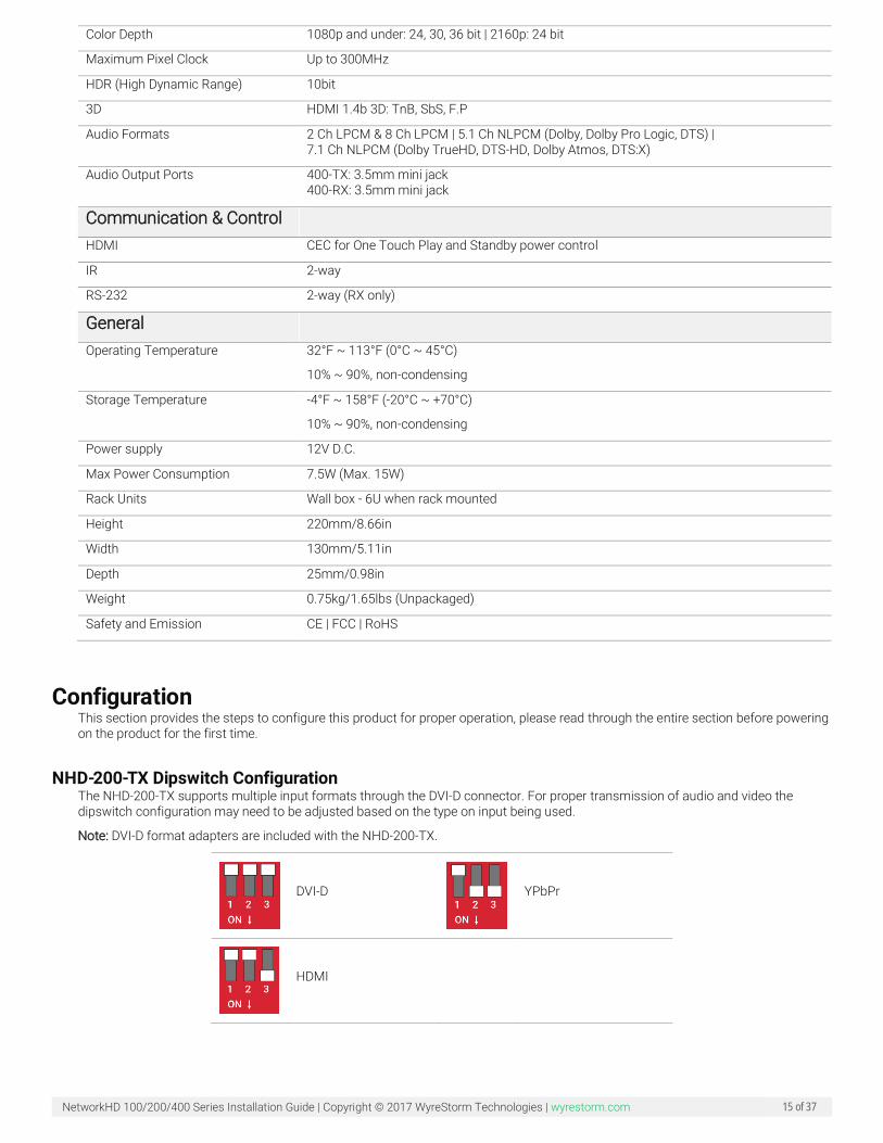
Color Depth 1080p and under: 24, 30, 36 bit | 2160p: 24 bit
Maximum Pixel Clock Up to 300MHz
HDR (High Dynamic Range) 10bit
3D HDMI 1.4b 3D: TnB, SbS, F.P
Audio Formats 2 Ch LPCM & 8 Ch LPCM | 5.1 Ch NLPCM (Dolby, Dolby Pro Logic, DTS) | 7.1 Ch NLPCM (Dolby TrueHD, DTS-HD, Dolby Atmos, DTS:X)
Audio Output Ports 400-TX: 3.5mm mini jack 400-RX: 3.5mm mini jack
Communication & Control
HDMI CEC for One Touch Play and Standby power control
IR 2-way
RS-232 2-way (RX only)
General
Operating Temperature 32°F ~ 113°F (0°C ~ 45°C)
10% ~ 90%, non-condensing
Storage Temperature -4°F ~ 158°F (-20°C ~ +70°C)
10% ~ 90%, non-condensing
Power supply 12V D.C.
Max Power Consumption 7.5W (Max. 15W)
Rack Units Wall box - 6U when rack mounted
Height 220mm/8.66in
Width 130mm/5.11in
Depth 25mm/0.98in
Weight 0.75kg/1.65lbs (Unpackaged)
Safety and Emission CE | FCC | RoHS
Configuration This section provides the steps to configure this product for proper operation, please read through the entire section before powering on the product for the first time.
NHD-200-TX Dipswitch Configuration The NHD-200-TX supports multiple input formats through the DVI-D connector. For proper transmission of audio and video the dipswitch configuration may need to be adjusted based on the type on input being used.
Note: DVI-D format adapters are included with the NHD-200-TX.
DVI-D
YPbPr
HDMI
NetworkHD 100/200/400 Series Installation Guide | Copyright © 2017 WyreStorm Technologies | wyrestorm.com 16 of 37
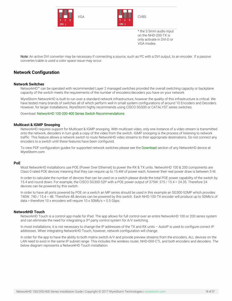
VGA
CVBS
* the 3.5mm audio input on the NHD-200-TX is only activate in DVI-D or VGA modes.
Note: An active DVI converter may be necessary if connecting a source, such as PC with a DVI output, to an encoder. If a passive converter/cable is used a color space issue may occur.
Network Configuration
Network Switches NetworkHD™ can be operated with recommended Layer 2 managed switches provided the overall switching capacity or backplane capacity of the switch meets the requirements of the number of encoders/decoders you have on your network.
WyreStorm NetworkHD is built to run over a standard network infrastructure, however the quality of this infrastructure is critical. We have tested many brands of switches all of which perform well in small system configurations of around 10 Encoders and Decoders. However, for larger installations, WyreStorm highly recommends using CISCO SG500 or CATALYST series switches.
Download: NetworkHD 100-200-400 Series Switch Recommendations
Multicast & IGMP Snooping NetworkHD requires support for Multicast & IGMP snooping. With multicast video, only one instance of a video stream is transmitted onto the network, decoders in turn grab a copy of the video from the switch. IGMP snooping is the process of listening to network traffic. This feature allows a network switch to route NetworkHD video streams to their appropriate destinations. Do not connect any encoders to a switch until these features have been configured.
To view PDF configuration guides for supported network switches please see the Download section of any NetworkHD device at WyreStorm.com
PoE Most NetworkHD installations use POE (Power Over Ethernet) to power the RX & TX units. NetworkHD 100 & 200 components are Class 0 rated POE devices meaning that they can require up to 15.4W of power each, however their real power draw is between 5-W.
In order to calculate the number of devices that can be used on a switch please divide the total POE power capability of the switch by 15.4 and round down. For example, the CISCO SG300-52P with a POE power output of 375W: 375 / 15.4 = 24.35. Therefore 24 devices can be powered by this switch.
In order to have all ports powered by POE on a switch an MP series should be used in this example an SG300-52MP which provides 740W. 740 / 15.4 = 48. Therefore 48 devices can be powered by this switch. Each NHD-100-TX encoder will produce up to 50Mb/s of data > therefore 10 x encoders will require 10 x 50Mb/s = 0.5 Gbps.
NetworkHD Touch NetworkHD Touch is a control app made for iPad. The app allows for full control over an entire NetworkHD 100 or 200 series system and can eliminate the need for integrating a 3rd party control system for A/V switching.
In most installations, it is not necessary to change the IP addresses of the TX and RX units – AutoIP is used to configure correct IP addresses. When integrating NetworkHD Touch, however, network configuration will change.
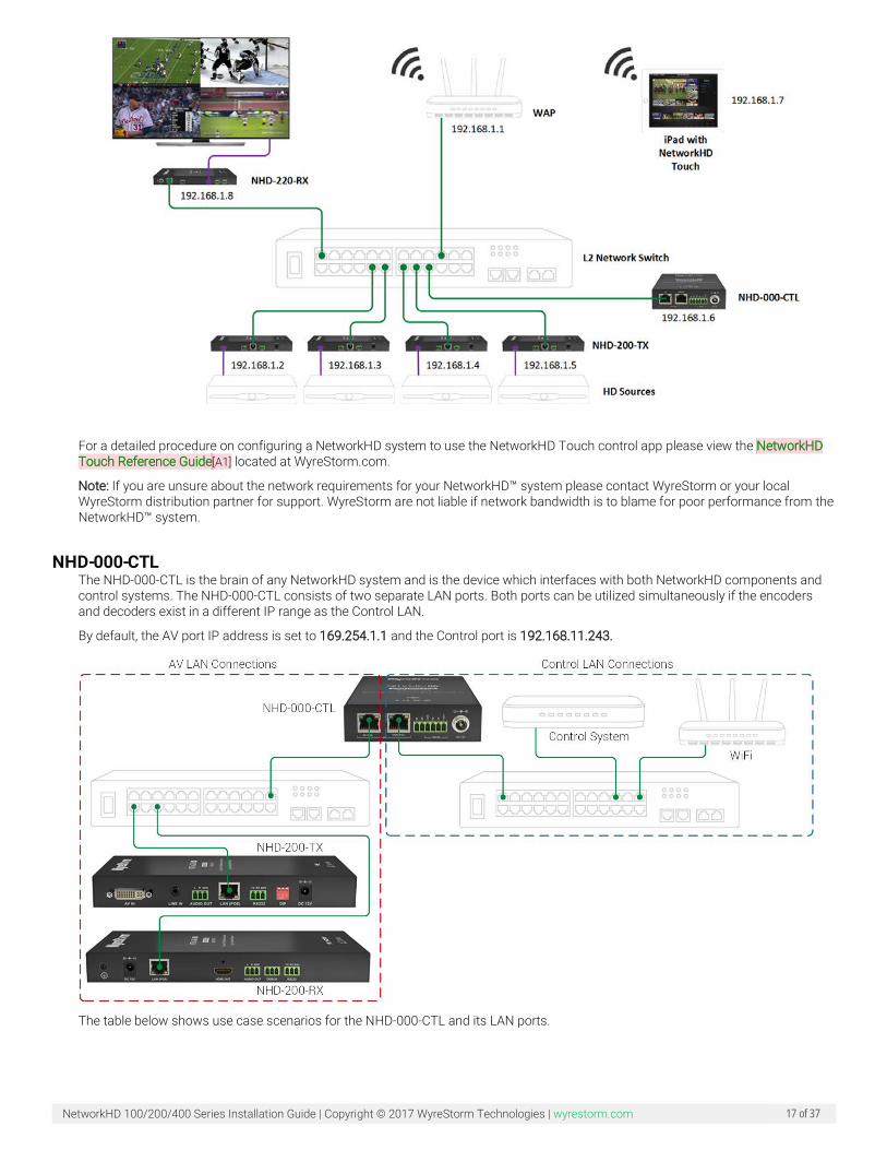
In order for the app to have the ability to both matrix switch A/V and provide preview streams from the encoders, ALL devices on the LAN need to exist in the same IP subnet range. This includes the wireless router, NHD-000-CTL and both encoders and decoders. The below diagram represents a NetworkHD Touch installation.
NetworkHD 100/200/400 Series Installation Guide | Copyright © 2017 WyreStorm Technologies | wyrestorm.com 17 of 37
For a detailed procedure on configuring a NetworkHD system to use the NetworkHD Touch control app please view the NetworkHD Touch Reference Guide[A1] located at WyreStorm.com.
Note: If you are unsure about the network requirements for your NetworkHD™ system please contact WyreStorm or your local WyreStorm distribution partner for support. WyreStorm are not liable if network bandwidth is to blame for poor performance from the NetworkHD™ system.
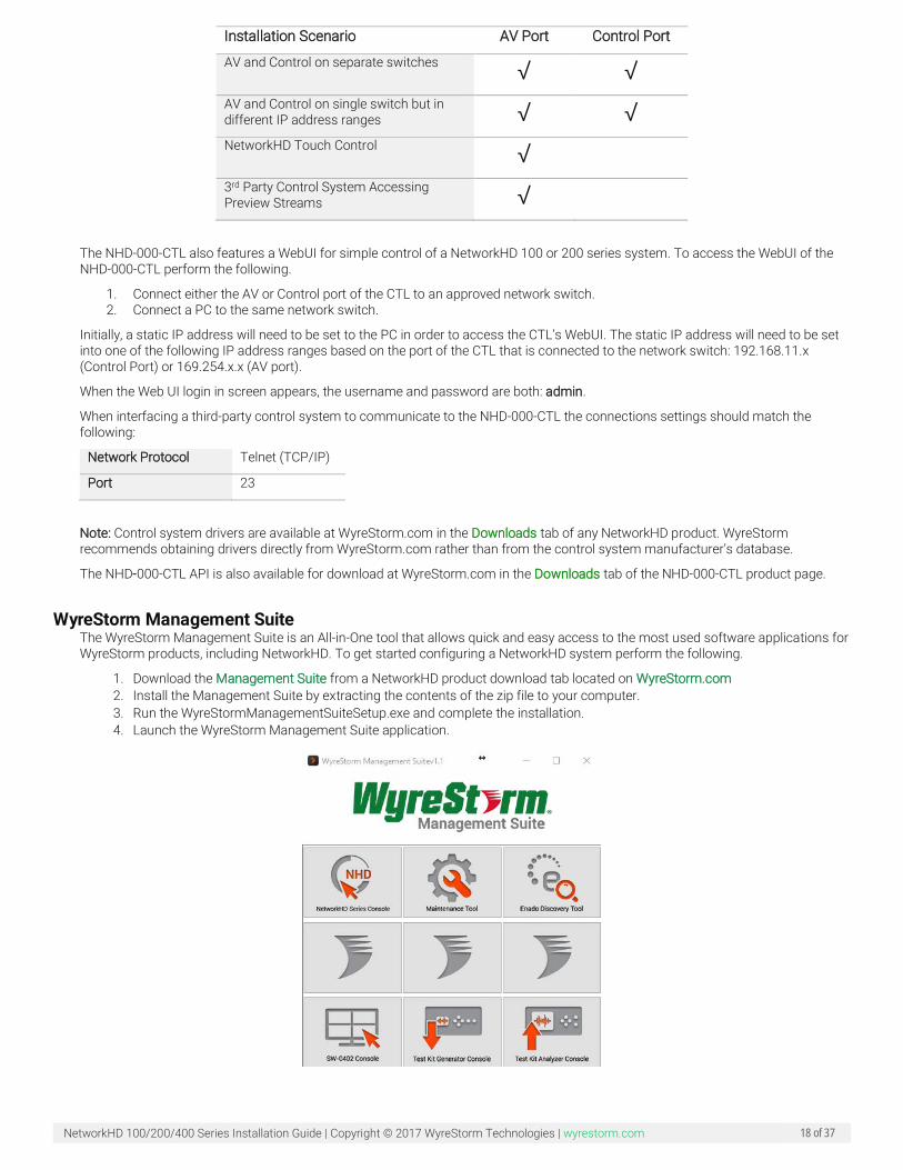
NHD-000-CTL The NHD-000-CTL is the brain of any NetworkHD system and is the device which interfaces with both NetworkHD components and control systems. The NHD-000-CTL consists of two separate LAN ports. Both ports can be utilized simultaneously if the encoders and decoders exist in a different IP range as the Control LAN.
By default, the AV port IP address is set to 169.254.1.1 and the Control port is 192.168.11.243.
The table below shows use case scenarios for the NHD-000-CTL and its LAN ports.
NetworkHD 100/200/400 Series Installation Guide | Copyright © 2017 WyreStorm Technologies | wyrestorm.com 18 of 37
Installation Scenario AV Port Control Port
AV and Control on separate switches √ √
AV and Control on single switch but in different IP address ranges √ √
NetworkHD Touch Control √
3rd Party Control System Accessing Preview Streams √
The NHD-000-CTL also features a WebUI for simple control of a NetworkHD 100 or 200 series system. To access the WebUI of the NHD-000-CTL perform the following.
1. Connect either the AV or Control port of the CTL to an approved network switch. 2. Connect a PC to the same network switch.
Initially, a static IP address will need to be set to the PC in order to access the CTL’s WebUI. The static IP address will need to be set into one of the following IP address ranges based on the port of the CTL that is connected to the network switch: 192.168.11.x (Control Port) or 169.254.x.x (AV port).
When the Web UI login in screen appears, the username and password are both: admin.
When interfacing a third-party control system to communicate to the NHD-000-CTL the connections settings should match the following:
Network Protocol Telnet (TCP/IP)
Port 23
Note: Control system drivers are available at WyreStorm.com in the Downloads tab of any NetworkHD product. WyreStorm recommends obtaining drivers directly from WyreStorm.com rather than from the control system manufacturer’s database.
The NHD-000-CTL API is also available for download at WyreStorm.com in the Downloads tab of the NHD-000-CTL product page.
WyreStorm Management Suite The WyreStorm Management Suite is an All-in-One tool that allows quick and easy access to the most used software applications for WyreStorm products, including NetworkHD. To get started configuring a NetworkHD system perform the following.
1. Download the Management Suite from a NetworkHD product download tab located on WyreStorm.com 2. Install the Management Suite by extracting the contents of the zip file to your computer. 3. Run the WyreStormManagementSuiteSetup.exe and complete the installation. 4. Launch the WyreStorm Management Suite application.
NetworkHD 100/200/400 Series Installation Guide | Copyright © 2017 WyreStorm Technologies | wyrestorm.com 19 of 37
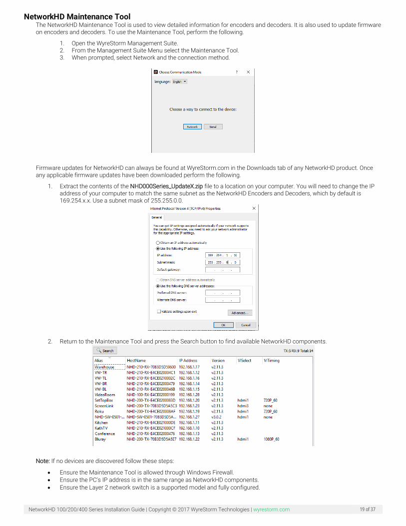
NetworkHD Maintenance Tool The NetworkHD Maintenance Tool is used to view detailed information for encoders and decoders. It is also used to update firmware on encoders and decoders. To use the Maintenance Tool, perform the following.
1. Open the WyreStorm Management Suite. 2. From the Management Suite Menu select the Maintenance Tool. 3. When prompted, select Network and the connection method.
Firmware updates for NetworkHD can always be found at WyreStorm.com in the Downloads tab of any NetworkHD product. Once any applicable firmware updates have been downloaded perform the following.
1. Extract the contents of the NHD000Series_UpdateX.zip file to a location on your computer. You will need to change the IP address of your computer to match the same subnet as the NetworkHD Encoders and Decoders, which by default is 169.254.x.x. Use a subnet mask of 255.255.0.0.
2. Return to the Maintenance Tool and press the Search button to find available NetworkHD components.
Note: If no devices are discovered follow these steps:
• Ensure the Maintenance Tool is allowed through Windows Firewall. • Ensure the PC’s IP address is in the same range as NetworkHD components. • Ensure the Layer 2 network switch is a supported model and fully configured.
NetworkHD 100/200/400 Series Installation Guide | Copyright © 2017 WyreStorm Technologies | wyrestorm.com 20 of 37
• Reboot your PC.
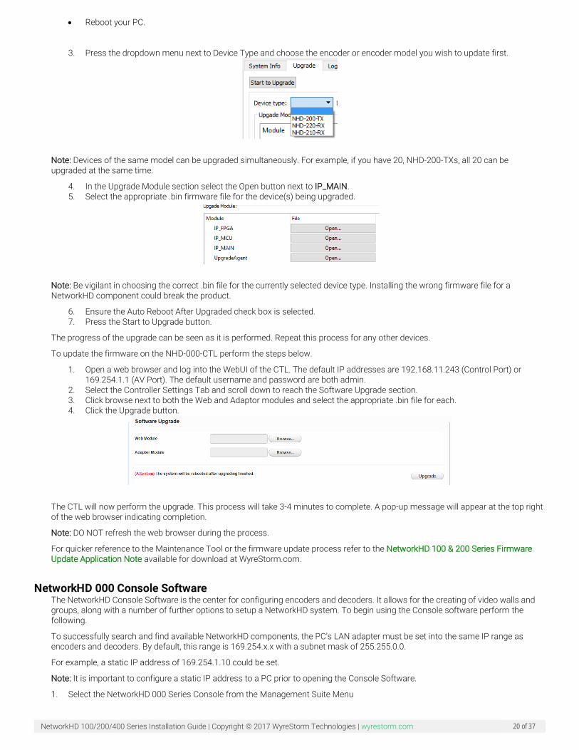
3. Press the dropdown menu next to Device Type and choose the encoder or encoder model you wish to update first.
Note: Devices of the same model can be upgraded simultaneously. For example, if you have 20, NHD-200-TXs, all 20 can be upgraded at the same time.
4. In the Upgrade Module section select the Open button next to IP_MAIN. 5. Select the appropriate .bin firmware file for the device(s) being upgraded.
Note: Be vigilant in choosing the correct .bin file for the currently selected device type. Installing the wrong firmware file for a NetworkHD component could break the product.
6. Ensure the Auto Reboot After Upgraded check box is selected. 7. Press the Start to Upgrade button.
The progress of the upgrade can be seen as it is performed. Repeat this process for any other devices.
To update the firmware on the NHD-000-CTL perform the steps below.
1. Open a web browser and log into the WebUI of the CTL. The default IP addresses are 192.168.11.243 (Control Port) or 169.254.1.1 (AV Port). The default username and password are both admin.
2. Select the Controller Settings Tab and scroll down to reach the Software Upgrade section. 3. Click browse next to both the Web and Adaptor modules and select the appropriate .bin file for each. 4. Click the Upgrade button.
The CTL will now perform the upgrade. This process will take 3-4 minutes to complete. A pop-up message will appear at the top right of the web browser indicating completion.
Note: DO NOT refresh the web browser during the process.
For quicker reference to the Maintenance Tool or the firmware update process refer to the NetworkHD 100 & 200 Series Firmware Update Application Note available for download at WyreStorm.com.
NetworkHD 000 Console Software The NetworkHD Console Software is the center for configuring encoders and decoders. It allows for the creating of video walls and groups, along with a number of further options to setup a NetworkHD system. To begin using the Console software perform the following.
To successfully search and find available NetworkHD components, the PC’s LAN adapter must be set into the same IP range as encoders and decoders. By default, this range is 169.254.x.x with a subnet mask of 255.255.0.0.
For example, a static IP address of 169.254.1.10 could be set.
Note: It is important to configure a static IP address to a PC prior to opening the Console Software.
1. Select the NetworkHD 000 Series Console from the Management Suite Menu
NetworkHD 100/200/400 Series Installation Guide | Copyright © 2017 WyreStorm Technologies | wyrestorm.com 21 of 37
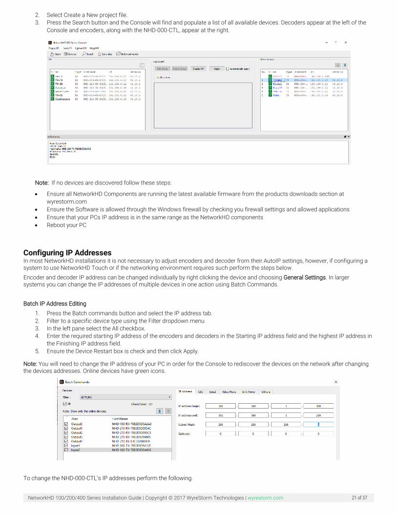
2. Select Create a New project file. 3. Press the Search button and the Console will find and populate a list of all available devices. Decoders appear at the left of the
Console and encoders, along with the NHD-000-CTL, appear at the right.
Note: If no devices are discovered follow these steps:
• Ensure all NetworkHD Components are running the latest available firmware from the products downloads section at wyrestorm.com
• Ensure the Software is allowed through the Windows firewall by checking you firewall settings and allowed applications • Ensure that your PCs IP address is in the same range as the NetworkHD components • Reboot your PC
Configuring IP Addresses In most NetworkHD installations it is not necessary to adjust encoders and decoder from their AutoIP settings, however, if configuring a system to use NetworkHD Touch or if the networking environment requires such perform the steps below. Encoder and decoder IP address can be changed individually by right clicking the device and choosing General Settings. In larger systems you can change the IP addresses of multiple devices in one action using Batch Commands. Batch IP Address Editing
1. Press the Batch commands button and select the IP address tab. 2. Filter to a specific device type using the Filter dropdown menu 3. In the left pane select the All checkbox. 4. Enter the required starting IP address of the encoders and decoders in the Starting IP address field and the highest IP address in
the Finishing IP address field. 5. Ensure the Device Restart box is check and then click Apply.
Note: You will need to change the IP address of your PC in order for the Console to rediscover the devices on the network after changing the devices addresses. Online devices have green icons.
To change the NHD-000-CTL’s IP addresses perform the following.
NetworkHD 100/200/400 Series Installation Guide | Copyright © 2017 WyreStorm Technologies | wyrestorm.com 22 of 37
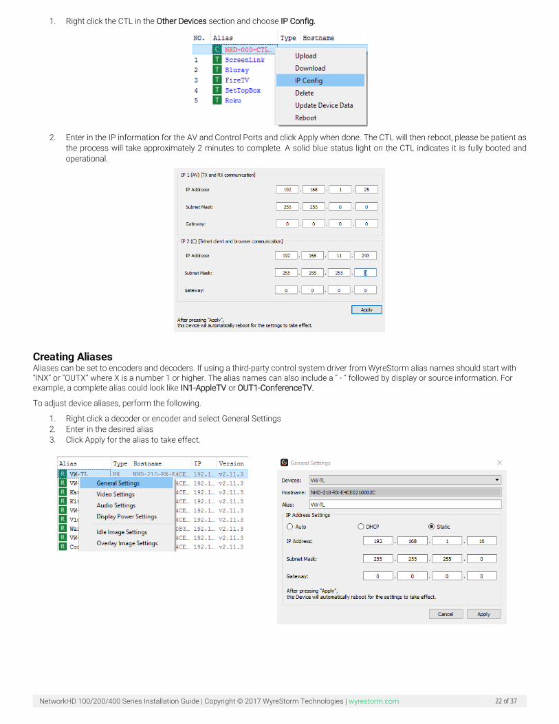
1. Right click the CTL in the Other Devices section and choose IP Config.
2. Enter in the IP information for the AV and Control Ports and click Apply when done. The CTL will then reboot, please be patient as
the process will take approximately 2 minutes to complete. A solid blue status light on the CTL indicates it is fully booted and operational.
Creating Aliases Aliases can be set to encoders and decoders. If using a third-party control system driver from WyreStorm alias names should start with “INX” or “OUTX” where X is a number 1 or higher. The alias names can also include a “ - “ followed by display or source information. For example, a complete alias could look like IN1-AppleTV or OUT1-ConferenceTV.
To adjust device aliases, perform the following.
1. Right click a decoder or encoder and select General Settings 2. Enter in the desired alias 3. Click Apply for the alias to take effect.
NetworkHD 100/200/400 Series Installation Guide | Copyright © 2017 WyreStorm Technologies | wyrestorm.com 23 of 37
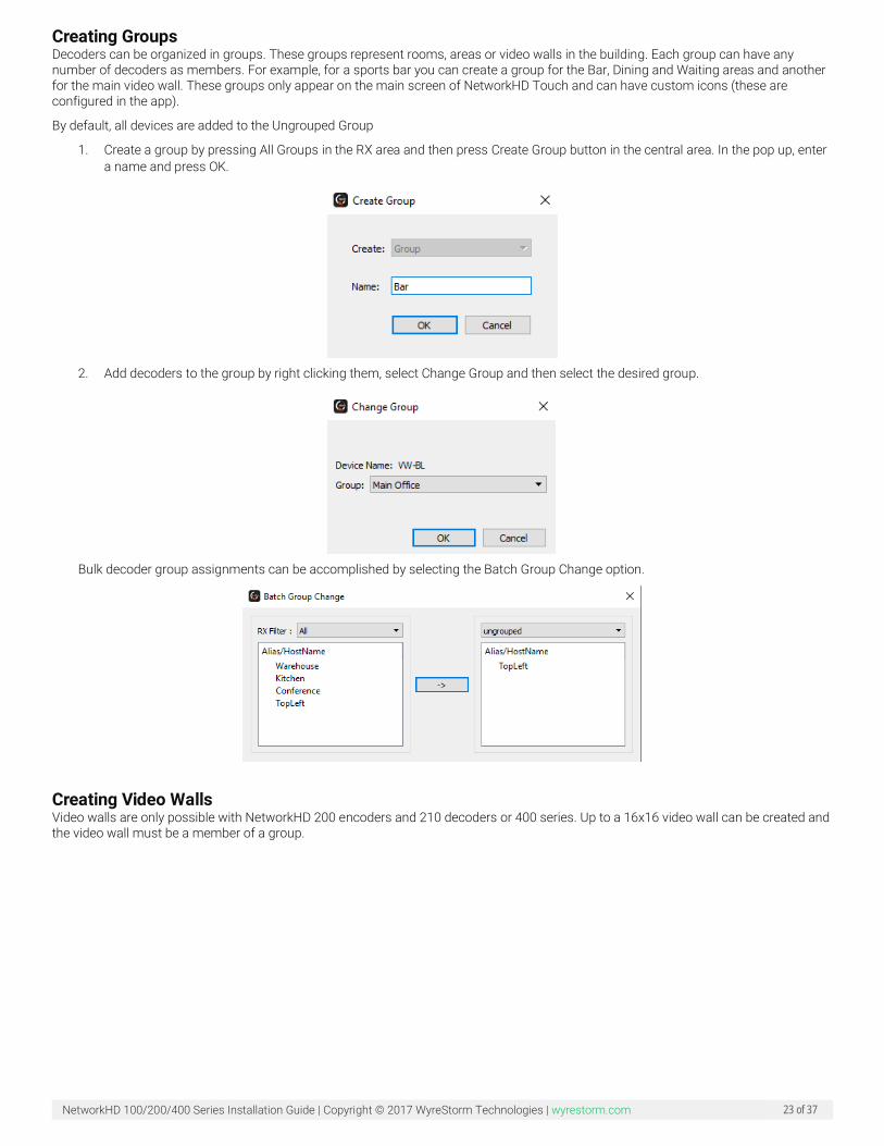
Creating Groups Decoders can be organized in groups. These groups represent rooms, areas or video walls in the building. Each group can have any number of decoders as members. For example, for a sports bar you can create a group for the Bar, Dining and Waiting areas and another for the main video wall. These groups only appear on the main screen of NetworkHD Touch and can have custom icons (these are configured in the app).
By default, all devices are added to the Ungrouped Group
1. Create a group by pressing All Groups in the RX area and then press Create Group button in the central area. In the pop up, enter a name and press OK.
2. Add decoders to the group by right clicking them, select Change Group and then select the desired group.
Bulk decoder group assignments can be accomplished by selecting the Batch Group Change option.
Creating Video Walls Video walls are only possible with NetworkHD 200 encoders and 210 decoders or 400 series. Up to a 16x16 video wall can be created and the video wall must be a member of a group.
NetworkHD 100/200/400 Series Installation Guide | Copyright © 2017 WyreStorm Technologies | wyrestorm.com 24 of 37
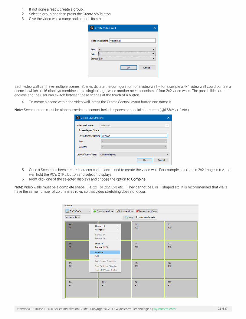
1. If not done already, create a group. 2. Select a group and then press the Create VW button. 3. Give the video wall a name and choose its size.
Each video wall can have multiple scenes. Scenes dictate the configuration for a video wall – for example a 4x4 video wall could contain a scene in which all 16 displays combine into a single image, while another scene consists of four 2x2 video walls. The possibilities are endless and the user can switch between these scenes at the touch of a button.
4. To create a scene within the video wall, press the Create Scene/Layout button and name it.
Note: Scene names must be alphanumeric and cannot include spaces or special characters (!@£$%^*\<+” etc.)
5. Once a Scene has been created screens can be combined to create the video wall. For example, to create a 2x2 image in a video
wall hold the PC’s CTRL button and select 4 displays. 6. Right click one of the selected displays and choose the option to Combine.
Note: Video walls must be a complete shape – ie. 2x1 or 2x2, 3x3 etc – They cannot be L or T shaped etc. It is recommended that walls have the same number of columns as rows so that video stretching does not occur.

NetworkHD 100/200/400 Series Installation Guide | Copyright © 2017 WyreStorm Technologies | wyrestorm.com 25 of 37
If using NetworkHD 200 series, the following prompt will appear asking for a Layout name. In this example, the 2x2 image could be called 2x2TopLeft.
7. Enter in a name and click the Ok button. When finished continue to step 11
If using NetworkHD 400 series a different window will appear asking to adjust for display bezel and gaps. It is not always necessary to adjust for bezel and gaps. However, if parts of the video image are being cut off, display measurements should be made to compensate appropriately
8. Start by giving the Layout a name. 9. Measure the OW (outer width), OH (outer height), VW (viewable width) and VH (viewable height) of a single screen which is part
of the video wall. Measurements should be recorded in centimeters and then multiplied by 100. For example, if the OW (outer width) of a display is 90cm, 90x100=9000. Once calculated, 9000 would be entered into the OW field. Repeat this process for all dimensions.
Each section of a video wall allows for the video image to be independently adjusted. To do this select the Advanced Settings tab.
10. Select a decoder and enter a value in the appropriate field. All values entered will be multiplied by 8
NetworkHD 100/200/400 Series Installation Guide | Copyright © 2017 WyreStorm Technologies | wyrestorm.com 26 of 37
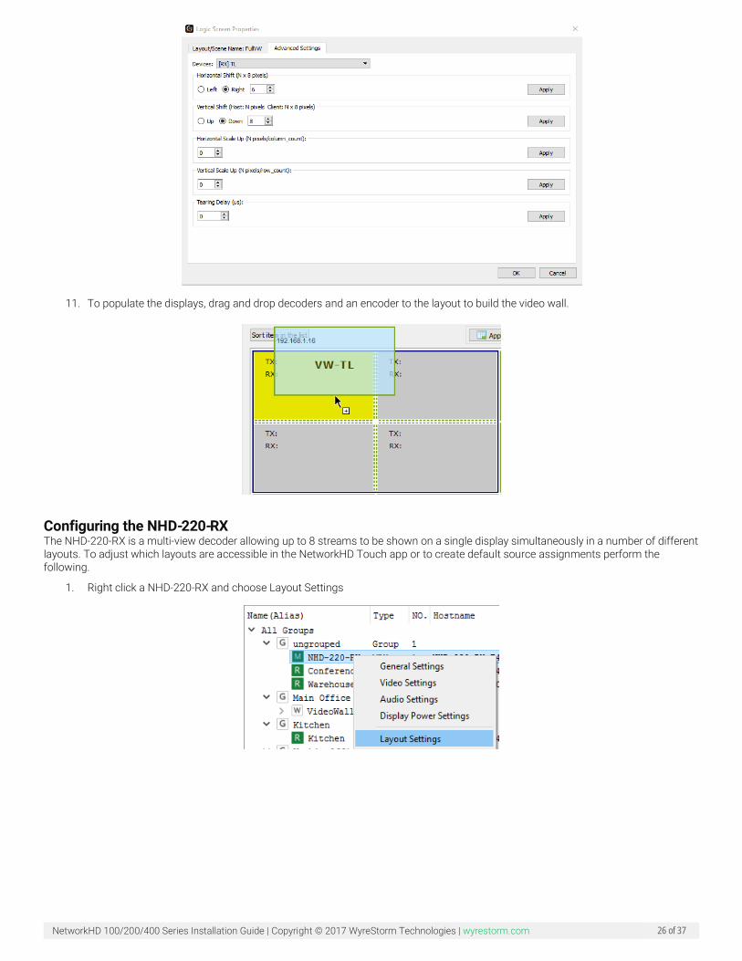
11. To populate the displays, drag and drop decoders and an encoder to the layout to build the video wall.
Configuring the NHD-220-RX The NHD-220-RX is a multi-view decoder allowing up to 8 streams to be shown on a single display simultaneously in a number of different layouts. To adjust which layouts are accessible in the NetworkHD Touch app or to create default source assignments perform the following.
1. Right click a NHD-220-RX and choose Layout Settings
NetworkHD 100/200/400 Series Installation Guide | Copyright © 2017 WyreStorm Technologies | wyrestorm.com 27 of 37
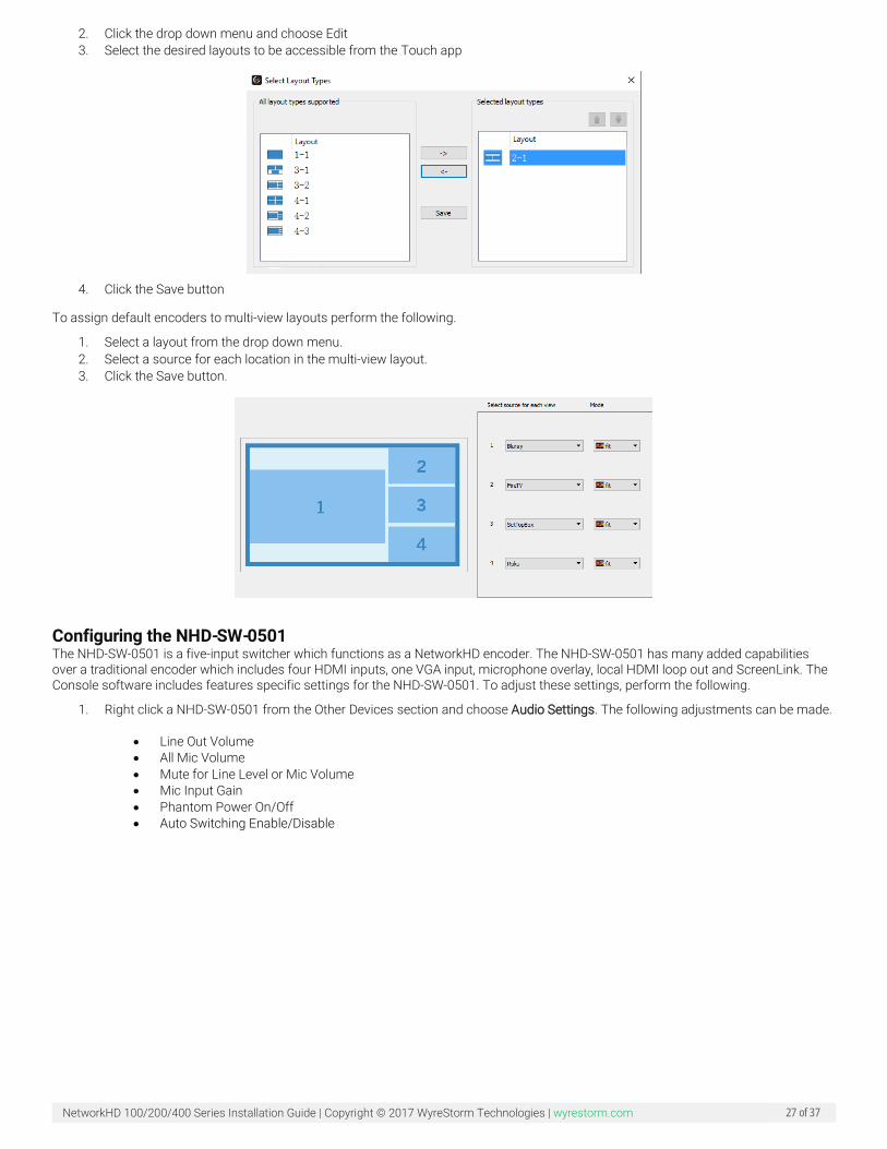
2. Click the drop down menu and choose Edit 3. Select the desired layouts to be accessible from the Touch app
4. Click the Save button
To assign default encoders to multi-view layouts perform the following.
1. Select a layout from the drop down menu. 2. Select a source for each location in the multi-view layout. 3. Click the Save button.
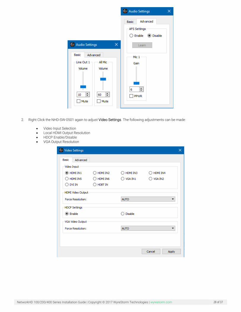
Configuring the NHD-SW-0501 The NHD-SW-0501 is a five-input switcher which functions as a NetworkHD encoder. The NHD-SW-0501 has many added capabilities over a traditional encoder which includes four HDMI inputs, one VGA input, microphone overlay, local HDMI loop out and ScreenLink. The Console software includes features specific settings for the NHD-SW-0501. To adjust these settings, perform the following.
1. Right click a NHD-SW-0501 from the Other Devices section and choose Audio Settings. The following adjustments can be made.
• Line Out Volume • All Mic Volume • Mute for Line Level or Mic Volume • Mic Input Gain • Phantom Power On/Off • Auto Switching Enable/Disable
NetworkHD 100/200/400 Series Installation Guide | Copyright © 2017 WyreStorm Technologies | wyrestorm.com 28 of 37
2. Right Click the NHD-SW-0501 again to adjust Video Settings. The following adjustments can be made:
• Video Input Selection • Local HDMI Output Resolution • HDCP Enable/Disable • VGA Output Resolution
NetworkHD 100/200/400 Series Installation Guide | Copyright © 2017 WyreStorm Technologies | wyrestorm.com 29 of 37
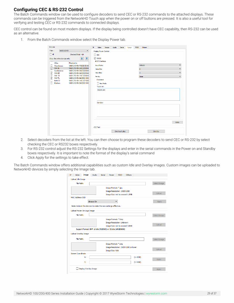
Configuring CEC & RS-232 Control The Batch Commands window can be used to configure decoders to send CEC or RS-232 commands to the attached displays. These commands can be triggered from the NetworkHD Touch app when the power on or off buttons are pressed. It is also a useful tool for verifying and testing CEC or RS-232 commands to connected displays.
CEC control can be found on most modern displays. If the display being controlled doesn’t have CEC capability, then RS-232 can be used as an alternative.
1. From the Batch Commands window select the Display Power tab.
2. Select decoders from the list at the left. You can then choose to program these decoders to send CEC or RS-232 by select
checking the CEC or RS232 boxes respectively. 3. For RS-232 control adjust the RS-232 Settings for the displays and enter in the serial commands in the Power on and Standby
boxes respectively. It is important to note the format of the display’s serial command 4. Click Apply for the settings to take effect.
The Batch Commands window offers additional capabilities such as custom Idle and Overlay images. Custom images can be uploaded to NetworkHD devices by simply selecting the Image tab.
NetworkHD 100/200/400 Series Installation Guide | Copyright © 2017 WyreStorm Technologies | wyrestorm.com 30 of 37
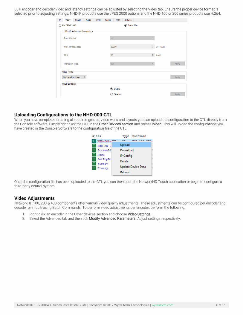
Bulk encoder and decoder video and latency settings can be adjusted by selecting the Video tab. Ensure the proper device format is selected prior to adjusting settings. NHD-IP products use the JPEG 2000 options and the NHD-100 or 200 series products use H.264.
Uploading Configurations to the NHD-000-CTL When you have completed creating all required groups, video walls and layouts you can upload the configuration to the CTL directly from the Console software. Simply right click the CTL in the Other Devices section and press Upload. This will upload the configurations you have created in the Console Software to the configuration file of the CTL.
Once the configuration file has been uploaded to the CTL you can then open the NetworkHD Touch application or begin to configure a third-party control system.
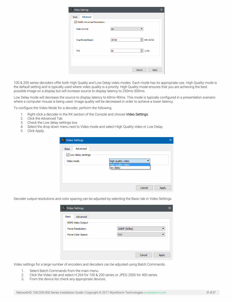
Video Adjustments NetworkHD 100, 200 & 400 components offer various video quality adjustments. These adjustments can be configured per encoder and decoder or in bulk using Batch Commands. To perform video adjustments per encoder, perform the following.
1. Right click an encoder in the Other devices section and choose Video Settings. 2. Select the Advanced tab and then tick Modify Advanced Parameters. Adjust settings respectively.
NetworkHD 100/200/400 Series Installation Guide | Copyright © 2017 WyreStorm Technologies | wyrestorm.com 31 of 37
100 & 200 series decoders offer both High Quality and Low Delay video modes. Each mode has its appropriate use. High Quality mode is the default setting and is typically used where video quality is a priority. High Quality mode ensures that you are achieving the best possible image on a display but will increase source to display latency to 250ms-300ms.
Low Delay mode will decrease the source to display latency to 60ms-90ms. This mode is typically configured in a presentation scenario where a computer mouse is being used. Image quality will be decreased in order to achieve a lower latency.
To configure the Video Mode for a decoder, perform the following.
1. Right click a decoder in the RX section of the Console and choose Video Settings. 2. Click the Advanced Tab 3. Check the Low delay settings box 4. Select the drop down menu next to Video mode and select High Quality video or Low Delay. 5. Click Apply.
Decoder output resolutions and color spacing can be adjusted by selecting the Basic tab in Video Settings.
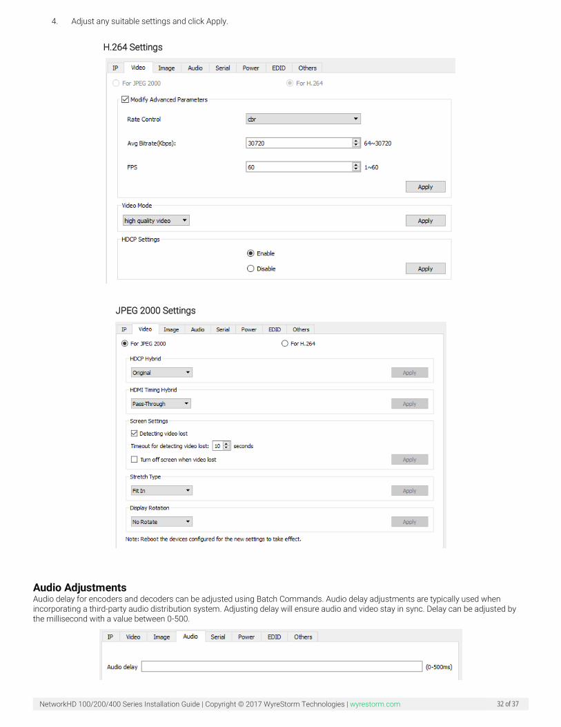
Video settings for a large number of encoders and decoders can be adjusted using Batch Commands.
1. Select Batch Commands from the main menu. 2. Click the Video tab and select H.264 for 100 & 200 series or JPEG 2000 for 400 series. 3. From the device list check any appropriate devices.
NetworkHD 100/200/400 Series Installation Guide | Copyright © 2017 WyreStorm Technologies | wyrestorm.com 32 of 37
4. Adjust any suitable settings and click Apply.
H.264 Settings
JPEG 2000 Settings
Audio Adjustments Audio delay for encoders and decoders can be adjusted using Batch Commands. Audio delay adjustments are typically used when incorporating a third-party audio distribution system. Adjusting delay will ensure audio and video stay in sync. Delay can be adjusted by the millisecond with a value between 0-500.
NetworkHD 100/200/400 Series Installation Guide | Copyright © 2017 WyreStorm Technologies | wyrestorm.com 33 of 37
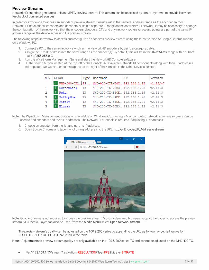
Preview Streams NetworkHD encoders generate a unicast MPEG preview stream. This stream can be accessed by control systems to provide live video feedback of connected sources.
In order for any device to access an encoder’s preview stream it must exist in the same IP address range as the encoder. In most NetworkHD installations, encoders and decoders exist in a separate IP range as the control/Wi-Fi network. It may be necessary to change the configuration of the network so that the encoders, decoders, CTL and any network routers or access points are part of the same IP address range as the device accessing the preview stream.
The following steps show how to access and configure an encoder’s preview stream using the latest version of Google Chrome running on a Windows PC.
1. Connect a PC to the same network switch as the NetworkHD encoders by using a category cable. 2. Assign the PC’s IP address into the same range as the encoder(s). By default, this will be in the 169.254.x.x range with a subnet
mask of 255.255.0.0. 3. Run the WyreStorm Management Suite and start the NetworkHD Console software. 4. Hit the search button located at the top left of the Console. All available NetworkHD components along with their IP addresses
will populate. NetworkHD encoders appear at the right of the Console in the Other Devices section.
Note: The WyreStorm Management Suite is only available on Windows OS. If using a Mac computer, network scanning software can be
used to find encoders and their IP addresses. The NetworkHD Console is required if adjusting IP addresses.
5. Choose an encoder from the list and note its IP address. 6. Open Google Chrome and type the following address into the URL: http://<Encoder_IP_Address>/stream
Note: Google Chrome is not required to access the preview stream. Most modern web browsers support the codec to access the preview stream. VLC Media Player can also be used, from the Media Menu select Open Network Stream.
The preview stream’s quality can be adjusted on the 100 & 200 series by appending the URL as follows. Accepted values for RESOLUTION, FPS & BITRATE are listed in the table.
Note: Adjustments to preview stream quality are only available on the 100 & 200 series TX and cannot be adjusted on the NHD-400-TX.
• http://192.168.1.55/stream?resolution=RESOLUTION&fps=FPS&bitrate=BITRATE
NetworkHD 100/200/400 Series Installation Guide | Copyright © 2017 WyreStorm Technologies | wyrestorm.com 34 of 37
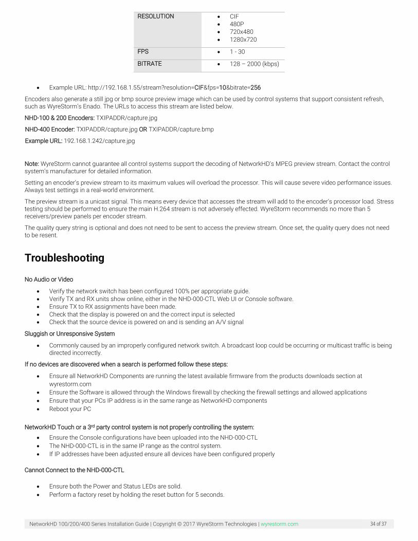
RESOLUTION • CIF • 480P • 720x480 • 1280x720
FPS • 1 - 30
BITRATE • 128 – 2000 (kbps)
• Example URL: http://192.168.1.55/stream?resolution=CIF&fps=10&bitrate=256
Encoders also generate a still jpg or bmp source preview image which can be used by control systems that support consistent refresh, such as WyreStorm’s Enado. The URLs to access this stream are listed below.
NHD-100 & 200 Encoders: TXIPADDR/capture.jpg
NHD-400 Encoder: TXIPADDR/capture.jpg OR TXIPADDR/capture.bmp
Example URL: 192.168.1.242/capture.jpg
Note: WyreStorm cannot guarantee all control systems support the decoding of NetworkHD’s MPEG preview stream. Contact the control system’s manufacturer for detailed information.
Setting an encoder’s preview stream to its maximum values will overload the processor. This will cause severe video performance issues. Always test settings in a real-world environment.
The preview stream is a unicast signal. This means every device that accesses the stream will add to the encoder’s processor load. Stress testing should be performed to ensure the main H.264 stream is not adversely effected. WyreStorm recommends no more than 5 receivers/preview panels per encoder stream.
The quality query string is optional and does not need to be sent to access the preview stream. Once set, the quality query does not need to be resent.
Troubleshooting
No Audio or Video
• Verify the network switch has been configured 100% per appropriate guide. • Verify TX and RX units show online, either in the NHD-000-CTL Web UI or Console software. • Ensure TX to RX assignments have been made. • Check that the display is powered on and the correct input is selected • Check that the source device is powered on and is sending an A/V signal
Sluggish or Unresponsive System
• Commonly caused by an improperly configured network switch. A broadcast loop could be occurring or multicast traffic is being directed incorrectly.
If no devices are discovered when a search is performed follow these steps:
• Ensure all NetworkHD Components are running the latest available firmware from the products downloads section at wyrestorm.com
• Ensure the Software is allowed through the Windows firewall by checking the firewall settings and allowed applications • Ensure that your PCs IP address is in the same range as NetworkHD components • Reboot your PC
NetworkHD Touch or a 3rd party control system is not properly controlling the system:
• Ensure the Console configurations have been uploaded into the NHD-000-CTL • The NHD-000-CTL is in the same IP range as the control system. • If IP addresses have been adjusted ensure all devices have been configured properly
Cannot Connect to the NHD-000-CTL
• Ensure both the Power and Status LEDs are solid. • Perform a factory reset by holding the reset button for 5 seconds.

NetworkHD 100/200/400 Series Installation Guide | Copyright © 2017 WyreStorm Technologies | wyrestorm.com 35 of 37
Note: Resetting the CTL will cause it to lose all TX and RX alias information. Alias Cannot Be Set
• If a device Alias cannot be set, another device may have been previously connected with the same Alias - ensure that the old device is offline and use the X in the CTL matrix to remove its record from the CTL.
Contacting Technical Support Should further clarification of the content of this manual or assistance on troubleshooting be required, please contact WyreStorm technical support.
Phone: North America: 844.280.WYRE (9973) | UK/EMEA: +44 (0) 1793 230 343 Email: [email protected]
On Line Chat (Accessible through website): http://WyreStorm.com/Contact-Tech-Support
Revision History V2.1 - 171107 - November 2017 Section Update
Preview Streams Added note to step 6 that adjustments are not available to the NHD-400-TX.
NetworkHD 100/200/400 Series Installation Guide | Copyright © 2017 WyreStorm Technologies | wyrestorm.com 36 of 37
Warranty and Service This product is covered by a 2 year limited parts and labor warranty. During this period there will be no charge for unit repair, component replacement or complete product replacement in the event of malfunction. The decision to repair or replace will be made by the manufacturer. This limited warranty only covers defects in materials or workmanship and excludes normal wear and tear or cosmetic damage. Visit the product page located at WyreStorm.com for additional information on this product including important technical information not provided in this document and warranty terms & conditions.
Warranty Limits & Exclusions 1. This Limited Warranty ONLY COVERS failures due to defects in materials or workmanship and DOES NOT COVER normal wear
and tear or cosmetic damage.
The limited warranty also DOES NOT COVER damage that occurs in shipment or failures caused by products not supplied by the warrantor, failures resulting from accident, misuse, abuse, neglect, mishandling, misapplication, alteration, incorrect installation, set-up adjustment, implementation of/to consumer controls, improper maintenance, power line surge, lightening damage, modification, service by anyone other than a manufacturer-approved service center or factory-authorized personnel, or damage attributable to acts of God.
2. There are no express warranties except as listed under “limited warranty coverage.” The warrantor is not liable for incidental or consequential damage resulting from the use of this product or arising out of any breach of this warranty.
For example: damages for lost time, the cost of having a person/persons remove or re-install previously installed equipment, travel to and from service location, loss of or damage to media, images, data or other recorded/stored content. The items listed here are not exclusive, but are for illustration only.
Parts and service not covered by this limited warranty are not the responsibility of the warrantor and should be considered the responsibility of the individual.
Obtaining Warranty Service Prior to returning a WyreStorm product for factory service, a service authorization must be obtained from a WyreStorm technical support representative. At the time of contact an address for shipping and an authorization number will be supplied. Refer to If no devices are discovered when a search is performed follow these steps:
• Ensure all NetworkHD Components are running the latest available firmware from the products downloads section at wyrestorm.com
• Ensure the Software is allowed through the Windows firewall by checking the firewall settings and allowed applications • Ensure that your PCs IP address is in the same range as NetworkHD components • Reboot your PC
NetworkHD Touch or a 3rd party control system is not properly controlling the system:
• Ensure the Console configurations have been uploaded into the NHD-000-CTL • The NHD-000-CTL is in the same IP range as the control system. • If IP addresses have been adjusted ensure all devices have been configured properly
Cannot Connect to the NHD-000-CTL
• Ensure both the Power and Status LEDs are solid. • Perform a factory reset by holding the reset button for 5 seconds.
Note: Resetting the CTL will cause it to lose all TX and RX alias information. Alias Cannot Be Set
• If a device Alias cannot be set, another device may have been previously connected with the same Alias - ensure that the old device is offline and use the X in the CTL matrix to remove its record from the CTL.
Contacting Technical Support for contact information.
When shipping a unit for service, carefully pack in the original packaging when available and send it prepaid, with adequate insurance. Please include a document or letter detailing the reason for return and include a daytime telephone number and/or email address where you can be contacted.

NetworkHD 100/200/400 Series Installation Guide | Copyright © 2017 WyreStorm Technologies | wyrestorm.com 37 of 37
If repair is required during the limited warranty period, the purchaser will be required to provide a sales receipt or other proof of purchase, indicating date and location of purchase as well as the price paid for the product. The customer will be charged for the repair of any unit received unless such information is provided.
Publication Disclaimer The material contained in this document consists of information that is the sole property of WyreStorm. This document is intended to provide information to allow interfacing to the relevant WyreStorm equipment by third party products.
WYRESTORM IS NOT RESPONSIBLE FOR MALFUNCTIONS AND/OR THE IN-OPERABILITY WHICH MAY BE CAUSED BY THE APPLICATION OF THIS INFORMATION, WHETHER EXPECTED OR NOT.
WyreStorm reserves the right to change software, control codes and specifications without notice.
WyreStorm will not be liable for any use of this information or any changes it may make to those products. The use of this information constitutes an agreement by the user to these limitations and exclusions.