network information book hunter valley north werris creek ... · added and diagram legend updated....
TRANSCRIPT
Division / Business Unit: Enterprise Services
Function: Operations
Document Type: Guideline
© Australian Rail Track Corporation Limited (ARTC)
Disclaimer
This document has been prepared by ARTC for internal use and may not be relied on by any other party without ARTC‟s prior written consent. Use of this document shall be subject
to the terms of the relevant contract with ARTC.
ARTC and its employees shall have no liability to unauthorised users of the information for any loss, damage, cost or expense incurred or arising by reason of an unauthorised user
using or relying upon the information in this document, whether caused by error, negligence, omission or misrepresentation in this document.
This document is uncontrolled when printed.
Authorised users of this document should visit ARTC‟s intranet or extranet (www.artc.com.au) to access the latest version of this document.
CONFIDENTIAL Page 1 of 48
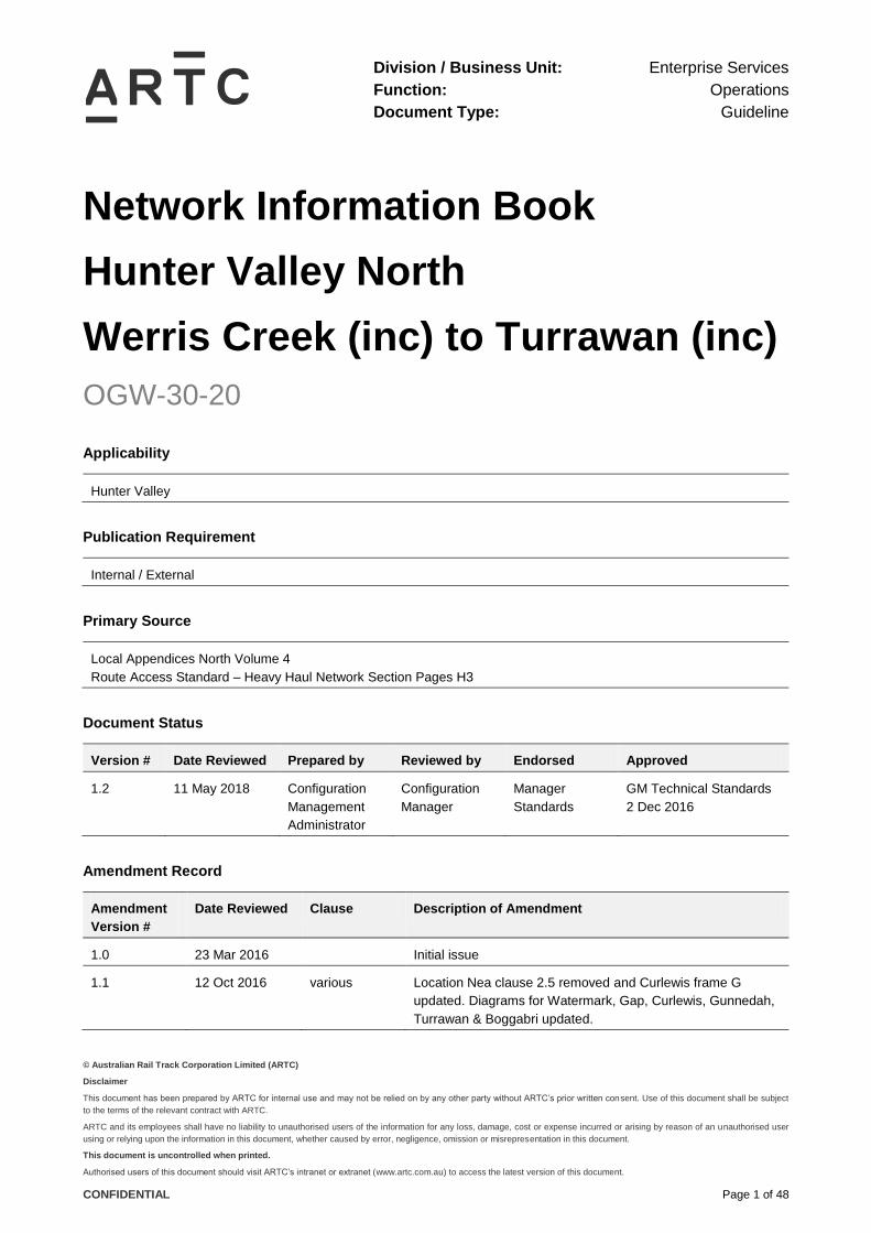
Network Information Book
Hunter Valley North
Werris Creek (inc) to Turrawan (inc)
OGW-30-20
Applicability
Hunter Valley
Publication Requirement
Internal / External
Primary Source
Local Appendices North Volume 4
Route Access Standard – Heavy Haul Network Section Pages H3
Document Status
Version # Date Reviewed Prepared by Reviewed by Endorsed Approved
1.2 11 May 2018 Configuration
Management
Administrator
Configuration
Manager
Manager
Standards
GM Technical Standards
2 Dec 2016
Amendment Record
Amendment
Version #
Date Reviewed Clause Description of Amendment
1.0 23 Mar 2016 Initial issue
1.1 12 Oct 2016 various Location Nea clause 2.5 removed and Curlewis frame G
updated. Diagrams for Watermark, Gap, Curlewis, Gunnedah,
Turrawan & Boggabri updated.

Werris Creek (inc) to Turrawan (inc)
OGW-30-20
Table of Contents
This document is uncontrolled when printed. Version Number: 1.2 Date Reviewed: 11 May 2018 Page 2 of 48
1.2 11 May 2018 Various Gunnedah residential area signs and new Boggabri Coal level
crossings added. Additional sidings and speed sign updates
on Werris Creek diagrams. Boggabri signal and Gunnedah
level crossing updates. Safety interface agreement details
added and diagram legend updated.
Werris Creek (inc) to Turrawan (inc)
OGW-30-20
Table of Contents
This document is uncontrolled when printed. Version Number: 1.2 Date Reviewed: 11 May 2018 Page 3 of 48
Table of Contents
Table of Contents ............................................................................................................................................. 3
1 General Information ............................................................................................................................... 5
1.1 Board Extent................................................................................................................................... 5
1.2 Safe Working System ..................................................................................................................... 5
1.3 Applicable Rules ............................................................................................................................ 5
1.4 Adjacent Train Control Centres ...................................................................................................... 5
1.5 Section Operating Equipment ........................................................................................................ 6
1.5.1 Motorised Point Machines .............................................................................................................. 6
1.5.2 Interlockings and Sidings ................................................................................................................ 6
1.6 Level Crossings .............................................................................................................................. 7
1.7 Maximum Permitted Speeds and Permanent Speed Restrictions ................................................. 9
1.8 Maximum Train Length .................................................................................................................. 9
1.9 Structure Clearances ..................................................................................................................... 9
1.10 Communications ............................................................................................................................ 9
1.11 Wayside Monitoring Systems ....................................................................................................... 10
1.12 Ruling Gradients .......................................................................................................................... 10
1.13 Curve and Gradient Data ............................................................................................................. 10
1.14 Drawing Legend ........................................................................................................................... 11
2 Locations and Sections Information .................................................................................................. 12
2.1 Werris Creek (WCK) .................................................................................................................... 12
2.1.1 Werris Creek South (WKS) ........................................................................................................... 13
2.1.2 Werris Creek Coal Siding ............................................................................................................. 15
2.1.3 Werris Creek Station..................................................................................................................... 16
2.1.4 Werris Creek (silo) Wheat Sidings ................................................................................................ 17
2.1.5 Werris Creek (Gap)....................................................................................................................... 18
2.2 Burilda (BUR) ............................................................................................................................... 21
2.3 Breeza (BZA)................................................................................................................................ 23
2.4 Watermark (WMK) ....................................................................................................................... 25
2.5 Curlewis (CLS) ............................................................................................................................. 27
2.6 Gunnedah (GDH) ......................................................................................................................... 30
2.6.1 Ground Frames Stock & Wheat Sidings ....................................................................................... 33
2.6.2 Working Arrangements for the Gunnedah Coal Loop ................................................................... 34
Werris Creek (inc) to Turrawan (inc)
OGW-30-20
Table of Contents
This document is uncontrolled when printed. Version Number: 1.2 Date Reviewed: 11 May 2018 Page 4 of 48
2.7 Emerald Hill (EHI) ........................................................................................................................ 36
2.8 Boggabri (BOG)............................................................................................................................ 38
2.8.1 Boggabri Maules Creek Branch Line ............................................................................................ 38
2.8.2 Boggabri Coal Balloon Loop ......................................................................................................... 39
2.9 Baan Baa (BAA) ........................................................................................................................... 43
2.10 Narrabri Coal (NCL) ..................................................................................................................... 45
2.11 Turrawan (TWN)........................................................................................................................... 47

Werris Creek (inc) to Turrawan (inc)
OGW-30-20
General Information
This document is uncontrolled when printed. Version Number: 1.2 Date Reviewed: 11 May 2018 Page 5 of 48
1 General Information
1.1 Board Extent
Werris Creek (inclusive) to Turrawan (inclusive).
This area is controlled by Newcastle North Network Controller.
Contact Numbers:
Phone: (02) 4902 7902
Train Transit Manager: (02) 4902 9410
Emergency: (02) 4902 7962
1.2 Safe Working System
Rail Vehicle Detection (RVD).
Operator keys are required for any sidings from Werris Creek to Turrawan.
1.3 Applicable Rules
The Network Rules and Procedures apply to the sections covered by this Information Book.
1.4 Adjacent Train Control Centres
John Holland Rail – North West Control Phone: 02 4028 9501
ARTC Upper Hunter 2 ph 02 4902 7911 Emergency 02 4902 7971
ARTC Train Order Control ph.02 4902 7916 Emergency 02 4902 7976

Werris Creek (inc) to Turrawan (inc)
OGW-30-20
General Information
This document is uncontrolled when printed. Version Number: 1.2 Date Reviewed: 11 May 2018 Page 6 of 48
1.5 Section Operating Equipment
1.5.1 Motorised Point Machines
All motorised points have a fixed nose; that means there are no swingnose points between Werris
Creek and Turrawan.
1.5.2 Interlockings and Sidings
Km Interlocking, Station, Platform or Siding Length of Passenger Platform (metres)
410.710 Werris Creek 100
415.829 Werris Creek (Gap)
420.822 Burilda
433.783 Breeza
446.110 Watermark
458.485 Curlewis Main, 122
475.556 Gunnedah Loop Line South, 140
476.560 Gunnedah Stockyards & Wheat siding
480.009 Gunnedah Coal Loop
493.097 Emerald Hill Main, 39
513.885 Boggabri Main 110
520.083 Boggabri East Maules Creek branch
521.414 Boggabri Coal Loop
531.016 Baan Baa
540.318 Narrabri Coal Loop
547.265 Turrawan

Werris Creek (inc) to Turrawan (inc)
OGW-30-20
General Information
This document is uncontrolled when printed. Version Number: 1.2 Date Reviewed: 11 May 2018 Page 7 of 48
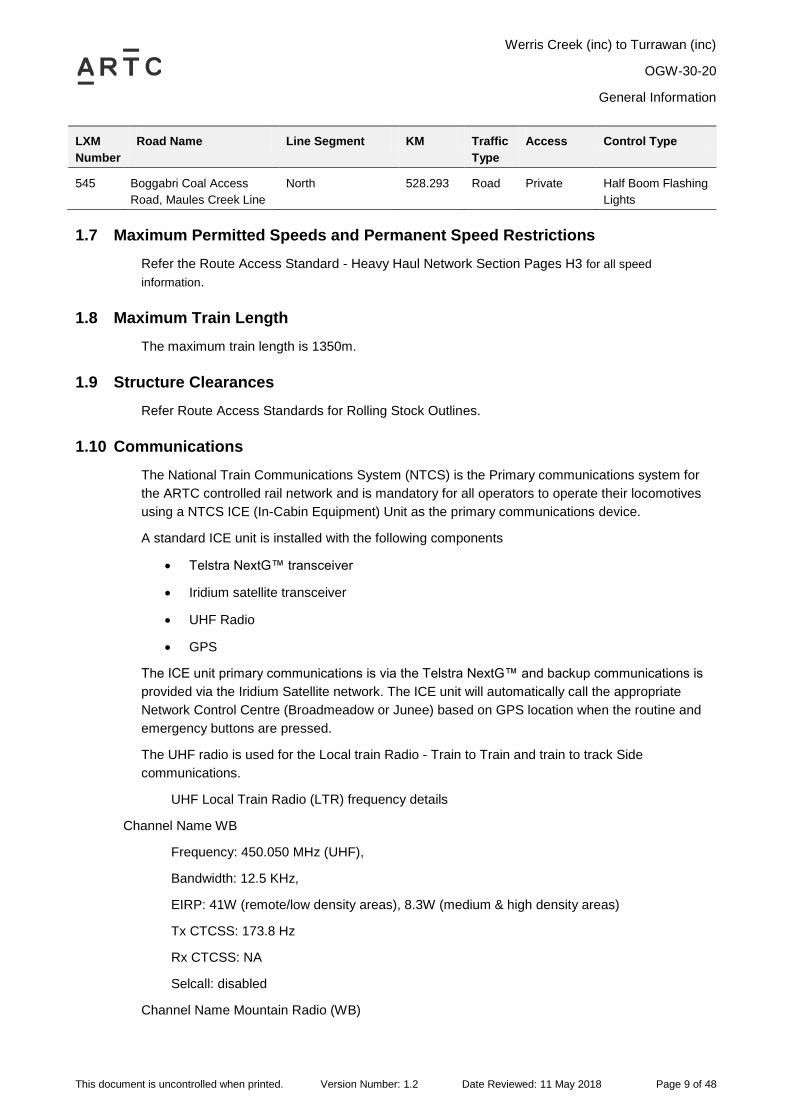
1.6 Level Crossings
LXM
Number
Road Name Line Segment KM Traffic
Type
Access Control Type
473 Single Street Main North 408.995 Public Primary Flashing
Lights
1809 Werris Creek Coal Siding
Lxing (South Street)
Werris Creek
Coal Siding
409.860 Public Stop Signs
474 Station Entrance
Werris Creek
Main North 411.187 Public Stop Signs
Station Entrance
Werris Creek
Werris Creek -
Mungindi
410.900 Private
4048 Werris Creek Lxing Werris Creek -
Mungindi
411.871 Private Stop Signs
4049 Gap Junction Lxing Werris Creek -
Mungindi
413.300 Private Stop Signs
514 Cana Road Werris Creek -
Mungindi
418.183 Public Stop Signs
515 Bulunbulun Road
Breeza
Werris Creek -
Mungindi
431.747 Public Stop Signs
516 Maitland Street
Breeza
Werris Creek -
Mungindi
433.416 Public Half Boom Flashing
Lights
3039 Breeza Lxing Werris Creek -
Mungindi
435.609 Private Stop Signs
3040 Breeza Lxing Werris Creek -
Mungindi
437.701 Private Stop Signs
3041 Breeza Lxing Werris Creek -
Mungindi
438.566 Private Stop Signs
3042 Breeza Lxing Werris Creek -
Mungindi
441.141 Private
3043 Breeza Lxing Werris Creek -
Mungindi
443.636 Private
517 Riordan Road Werris Creek -
Mungindi
444.903 Public Stop Signs
518 Watermark Lxing Werris Creek -
Mungindi
448.524 Public Stop Signs
519 Spring Ridge Road
Nea
Werris Creek -
Mungindi
450.556 Public Stop Signs
520 Kamilaroi Highway
Curlewis
Werris Creek -
Mungindi
457.930 Public Half Boom Flashing
Lights
3045 Curlewis Lxing Werris Creek -
Mungindi
460.413 Private
3046 Curlewis Lxing Werris Creek -
Mungindi
463.572 Private
Werris Creek (inc) to Turrawan (inc)
OGW-30-20
General Information
This document is uncontrolled when printed. Version Number: 1.2 Date Reviewed: 11 May 2018 Page 8 of 48
LXM
Number
Road Name Line Segment KM Traffic
Type
Access Control Type
3047 Gunnedah Lxing Werris Creek -
Mungindi
465.885 Private Stop Signs
3048 Gunnedah Lxing Werris Creek -
Mungindi
468.650 Private
521 Kamilaroi Road
Gunnedah
Werris Creek -
Mungindi
470.520 Public Stop Signs
522 Carroll Street
Gunnedah
Werris Creek -
Mungindi
474.166 Public Half Boom Flashing
Lights
523 Marquis Street
Gunnedah
Werris Creek -
Mungindi
475.476 Public Half Boom Flashing
Lights
524 New Street
Gunnedah
Werris Creek -
Mungindi
476.330 Public Primary Flashing
Lights
3049 Gunnedah Lxing Werris Creek -
Mungindi
481.460 Public
526 Rothsay Crossing
Emerald Hill
Werris Creek -
Mungindi
486.424 Public Stop Signs
527 Goolhi Road
Emerald Hill
Werris Creek -
Mungindi
493.063 Public Half Boom Flashing
Lights
3050 Emerald Hill Lxing Werris Creek -
Mungindi
496.100 Private
528 Binnalong Road
Boggabri
Werris Creek -
Mungindi
509.036 Public Stop Signs
529 Boston Street
Boggabri
Werris Creek -
Mungindi
515.775 Public Half Boom Flashing
Lights
530 Stock Route Werris Creek -
Mungindi
516.780 Public Stop Signs
531 Caloola Road
Baan Baa
Werris Creek -
Mungindi
530.780 Public Half Boom Flashing
Lights
532 Longsight Crossing
Baan Baa
Werris Creek -
Mungindi
532.472 Public Stop Signs
1826 Baan Baa Lxing Werris Creek -
Mungindi
535.147 Public Stop Signs
533 Turrawan Lxing Werris Creek -
Mungindi
537.259 Public Stop Signs
534 Narrabri Coal Lxing
Turrawan
Werris Creek -
Mungindi
540.297 Public Half Boom Flashing
Lights
535 Greylands Crossing
Turrawan
Werris Creek -
Mungindi
544.072 Public Stop Signs
1900 Turrawan Lxing Werris Creek -
Mungindi
546.811 Public Stop Signs
544 Boggabri Coal Access
Road, Boggabri Coal Line
North 528.270 Road Private Half Boom Flashing
Lights
Werris Creek (inc) to Turrawan (inc)
OGW-30-20
General Information
This document is uncontrolled when printed. Version Number: 1.2 Date Reviewed: 11 May 2018 Page 9 of 48
LXM
Number
Road Name Line Segment KM Traffic
Type
Access Control Type
545 Boggabri Coal Access
Road, Maules Creek Line
North 528.293 Road Private Half Boom Flashing
Lights
1.7 Maximum Permitted Speeds and Permanent Speed Restrictions
Refer the Route Access Standard - Heavy Haul Network Section Pages H3 for all speed
information.
1.8 Maximum Train Length
The maximum train length is 1350m.
1.9 Structure Clearances
Refer Route Access Standards for Rolling Stock Outlines.
1.10 Communications
The National Train Communications System (NTCS) is the Primary communications system for
the ARTC controlled rail network and is mandatory for all operators to operate their locomotives
using a NTCS ICE (In-Cabin Equipment) Unit as the primary communications device.
A standard ICE unit is installed with the following components
Telstra NextG™ transceiver
Iridium satellite transceiver
UHF Radio
GPS
The ICE unit primary communications is via the Telstra NextG™ and backup communications is
provided via the Iridium Satellite network. The ICE unit will automatically call the appropriate
Network Control Centre (Broadmeadow or Junee) based on GPS location when the routine and
emergency buttons are pressed.
The UHF radio is used for the Local train Radio - Train to Train and train to track Side
communications.
UHF Local Train Radio (LTR) frequency details
Channel Name WB
Frequency: 450.050 MHz (UHF),
Bandwidth: 12.5 KHz,
EIRP: 41W (remote/low density areas), 8.3W (medium & high density areas)
Tx CTCSS: 173.8 Hz
Rx CTCSS: NA
Selcall: disabled
Channel Name Mountain Radio (WB)

Werris Creek (inc) to Turrawan (inc)
OGW-30-20
General Information
This document is uncontrolled when printed. Version Number: 1.2 Date Reviewed: 11 May 2018 Page 10 of 48
Frequency: 450.050 MHz (UHF),
Bandwidth: 12.5 KHz,
EIRP: 41W (remote/low density areas), 8.3W (medium & high density areas)
Tx CTCSS: 103.5 Hz
Rx CTCSS: NA
Selcall: disabled
Alternate Communication for this section is by mobile or satellite phones.
1.11 Wayside Monitoring Systems
There are no wayside monitoring systems in place in this section.
1.12 Ruling Gradients
Down 1 in 52
Up 1 in 75
1.13 Curve and Gradient Data
For all Curve and Gradient data, refer to the ARTC Internet.
https://extranet.artc.com.au/eng_network-config_cd.html
Werris Creek (inc) to Turrawan (inc)
OGW-30-20
General Information
This document is uncontrolled when printed. Version Number: 1.2 Date Reviewed: 11 May 2018 Page 11 of 48
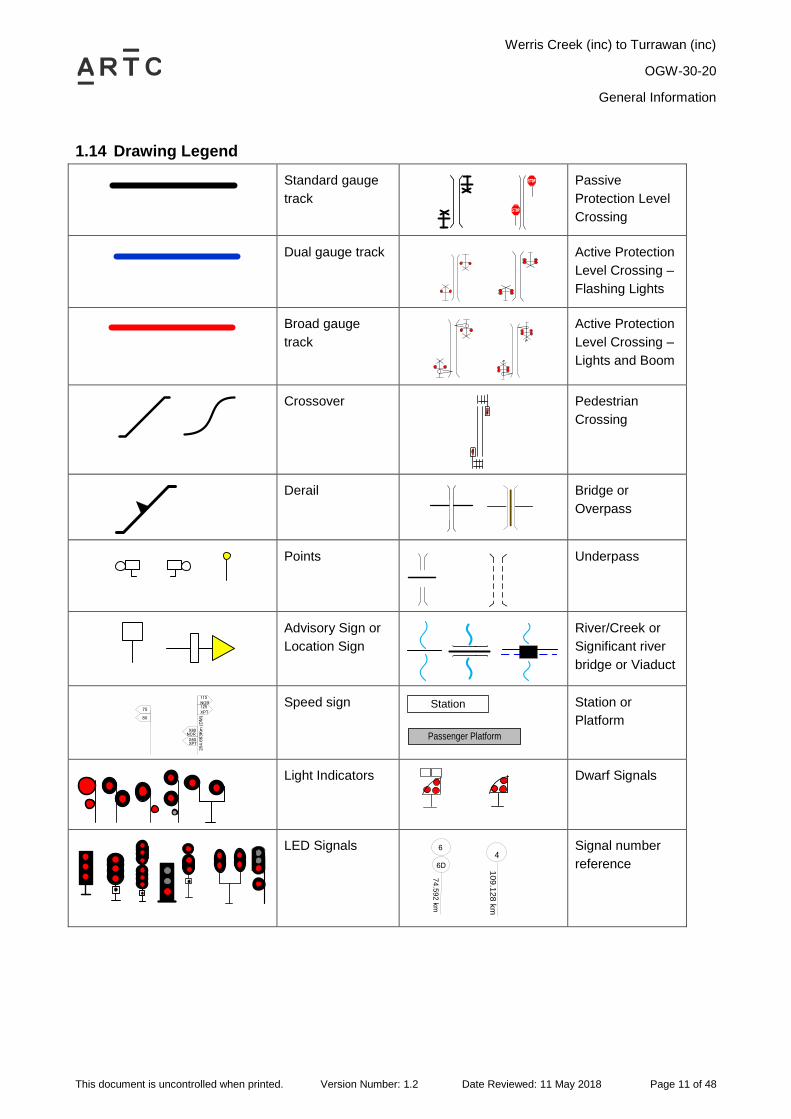
1.14 Drawing Legend
Standard gauge
track
Passive
Protection Level
Crossing
Dual gauge track
Active Protection
Level Crossing –
Flashing Lights
Broad gauge
track
Active Protection
Level Crossing –
Lights and Boom
Crossover
Pedestrian
Crossing
Derail
Bridge or
Overpass
Points
Underpass
Advisory Sign or
Location Sign
River/Creek or
Significant river
bridge or Viaduct
75
80
20
4.6
63
Km
(D
M)
X80
X80
115NOR125XPT
NOR
XPT
Speed sign Station
Passenger Platform
Station or
Platform
Light Indicators
Dwarf Signals
LED Signals
74
.59
2 k
m
6
6D
10
9.1
28
km
4
Signal number
reference
Werris Creek (inc) to Turrawan (inc)
OGW-30-20
Locations and Sections Information
This document is uncontrolled when printed. Version Number: 1.2 Date Reviewed: 11 May 2018 Page 12 of 48
2 Locations and Sections Information
2.1 Werris Creek (WCK)
General Arrangements
Werris Creek is a Rail Vehicle Detection location controlled from Network Control Centre North.
It is a consolidated location, incorporating locations previously known as Werris Creek South,
Werris Creek and Gap.
There is a substantial yard on the Down side, utilising ground frames, managed by Pacific
National.
Goods loop 1380 metres
Up loop 789 metres
Operation of Points and Signals
The points and signals on the Mainline and Loop line at Werris Creek are power operated and
controlled by track circuit and cannot be moved unless the track indicator diagram is showing that
the track(s) controlling the points is unoccupied.
Other
For ease of understanding, the Werris Creek location is described under several discrete
headings in this Network Information Book:
Werris Creek (South)
Werris Creek Coal Siding
Werris Creek Station
Werris Creek (silo) Wheat Sidings and
Werris Creek (Gap)
Werris Creek (inc) to Turrawan (inc)
OGW-30-20
Locations and Sections Information
This document is uncontrolled when printed. Version Number: 1.2 Date Reviewed: 11 May 2018 Page 13 of 48
2.1.1 Werris Creek South (WKS)
Single Street Level Crossing
Type F flashing lights and bells are provided at Single Street level crossing at the 408.995km
mark.
The warning equipment is automatically controlled by track circuit for Down and Up trains, subject
to the clearance of the signals on each side of the crossing.
If a train closely approaches Down outer home signal no.23 or Up starting signal no.5 at stop, the
setting of the applicable signal route will cause the level crossing warning indicators to be
displayed, but clearing of the signals will be delayed for 15 seconds.
If it becomes necessary to hold a train at signal no.23 or no.5 after the signal has been cleared,
the level crossing warning indicators will continue to be displayed for a period of 120 seconds
after the signal is returned to stop, and will then cancel automatically.
Ground Frame
Lever B
Lever B is located on the Up side of the main line adjacent to the points and provides access to
the Up Loop line.
Lever B is unlocked by the releasing switch from the Network Controller Network Control Centre
North.
Working on the Goods Loop
The Goods loop is on a falling grade towards Werris Creek station and must not be used for
shunting purposes. When a train arrives in the Goods loop, the locomotive must be released with
the least possible delay.
Before the locomotive is detached, the train must be secured by applying sufficient vehicle
handbrakes to prevent the train from moving on the falling grade. The employee who detaches
the locomotive will be responsible for securing the train.
The terminal operator will be responsible for advising the Network Controller immediately all
vehicles are clear for the passage of a train from the main line to the Goods loop.
EXCEPTION: Traffic for Werris Creek station may be placed in the Goods loop, provided that this
traffic is accompanied by a Qualified Worker. The Qualified Worker must secure
the vehicles with handbrakes while waiting for the arrival of a locomotive at the
country end of the Goods Loop, before being placed where required by the
terminal operator.
When the locomotive is attached to the vehicles, the automatic air brake must be connected and
operating on all vehicles being shunted to the country end of the loop line and, when the
locomotive is detached, the vehicles must be secured by handbrakes.
EXCEPTION: There is a TOC Waiver (#14017 16/12/2014) allowing a special procedure for
Pacific National running around coal trains to and from Werris Creek coal siding
without applying handbrakes.
Werris Creek (inc) to Turrawan (inc)
OGW-30-20
Locations and Sections Information
This document is uncontrolled when printed. Version Number: 1.2 Date Reviewed: 11 May 2018 Page 14 of 48
Freight Trains Entering the Yard
All rail traffic entering the non-track circuited shunting yard must have authority from the Werris
Creek Operations Supervisor.
Up freight trains must not be allowed to enter Nos. 1, 2, 4, 7, 9, 10, 11 and 12 sidings until the
Qualified Worker has provided an assurance to the Network Controller that the siding concerned
will be kept clear for the entry of the train. The Qualified Worker must inform the Driver of the
movements required and ensure that the points over which the train will pass are in the proper
position.
Securing Vehicles in Yard
As the roads in the shunting yard are on a grade falling away from Sydney, vehicles placed in the
siding must be secured with handbrakes.
Admitting Locomotives to and from the Locomotive Depot
A stop sign is provided 50 metres from No.2 points in the locomotive arrival road at the
Quipolly end of the yard. Outgoing locomotives must not be permitted to enter No.2 shunting
neck until directed to do so by the Werris Creek Operations Supervisor, after ensuring that
the vehicular roadway is clear in both directions.
Two stop signs are provided at the points leading from the locomotive release road to No. 2
shunting neck for locomotives entering or departing the locomotive depot. All locomotives must
be brought to a stand at the stop sign, and:
Must not proceed until instructed by the Werris Creek Operations Supervisor.
A stop sign is provided alongside No.1 locomotive road and locomotives proceeding from the
locomotive depot must not pass this stop sign, until authorised to do so by the Werris Creek
Operations Supervisor.
Refer safety interface agreements IA1601, IA1602 and IA1603 for further details regarding
sidings in Werris Creek yard.

Werris Creek (inc) to Turrawan (inc)
OGW-30-20
Locations and Sections Information
This document is uncontrolled when printed. Version Number: 1.2 Date Reviewed: 11 May 2018 Page 15 of 48
2.1.2 Werris Creek Coal Siding
General Arrangements
Balloon Loop length: 1664 metres
Coal siding length: 1383 metres (clear of the balloon loop)
Arrival road: over 1350 metres (clear of road crossing and the balloon loop)
The Werris Creek Coal Siding is a private siding consisting of a balloon loop and a siding, both of
which can pass through the coal loader.
Access to the coal siding is from the Up end of the Goods Loop. This requires all trains to run-
around on the goods loop to put the locos on the Sydney end. Trains may be stabled unattended
in the loop and siding.
Access to and from the Coal Siding is by the ARTC signals provided. The ARTC Network
Controller will set the route and the shunt signal will display a yellow indication for entry into the
Coal siding.
Rail Traffic Departing the Werris Creek Coal Siding
When arriving at the stop sign, the driver will contact the ARTC Network Controller at the Network
Control Centre North and request authority to depart. The Network Controller will give permission
to pass the stop board and clear 15-27 shunt signal. The train will then proceed onto the Goods
Loop and prepare to run around.
Werris Creek (inc) to Turrawan (inc)
OGW-30-20
Locations and Sections Information
This document is uncontrolled when printed. Version Number: 1.2 Date Reviewed: 11 May 2018 Page 16 of 48
2.1.3 Werris Creek Station
General Arrangements
The station platform is triangular shaped, at the junction between the Main North line to Armidale,
and the North-West Main to Narrabri / Moree / North Star.
The NSW Trains Explorer train (NP23 / 43 and NP24 / 44) divides on the Down, and combines on
the Up at Werris Creek (Station).
Working Trains to Armidale Line (CRN)
Signal 15-49 will be kept at stop until the driver advises that they have a valid Train Order for the
section towards Armidale. Once the driver has obtained a Train Order from CRN Train Order
Control, the driver must notify NCCN North Board Network Controller of the order/authority
number, and the Network Controller should then clear the MLI, which will display a pulsating
white aspect.
Traffic may proceed only to the “Shunt Limit” sign at 411.101km, without possession of a Train
Order. There is only 94 metres clear of G-frame points to the Shunt Limit.
Ground Frames
Frame G
Frame G is located on the Up side of the Main North line adjacent to the crossover and provides
access to the Up Loop.
Frame G is unlocked by the releasing switch from the Network Controller NCCN.
Traffic may proceed only to the Shunt Limit sign at 411.101km, without possession of a Train
Order.
Note: Trains must not traverse 104 points (reversed) to/from the North West main. With 104
points reversed, trains must only proceed to/from Main North line (Armidale side).
Werris Creek (inc) to Turrawan (inc)
OGW-30-20
Locations and Sections Information
This document is uncontrolled when printed. Version Number: 1.2 Date Reviewed: 11 May 2018 Page 17 of 48
2.1.4 Werris Creek (silo) Wheat Sidings
A private siding located on the up side of the mainline between the station platform and Werris
Creek (Gap).
Propelling Trains
Trains may be propelled from Frame Q to Werris Creek shunting yards, under control of signals.
The Driver must sound the locomotive whistle freely while approaching the private level crossing
at 411.871 km and the Qualified Worker must be prepared to stop the train at this level crossing if
it is obstructed.
Ground Frames
Frame J
Frame J is located on the Up side of the main line adjacent to the crossover and provides access
to Werris Creek Bulk Wheat sidings.
Frame J is unlocked by the releasing switch from the Network Controller NCCN.
Frame Q
Frame Q is located on the Down side of the main line adjacent to the crossover and provides
access to Werris Creek Bulk Wheat sidings.
Frame Q is unlocked by the releasing switch from the Network Controller NCCN.
Werris Creek (inc) to Turrawan (inc)
OGW-30-20
Locations and Sections Information
This document is uncontrolled when printed. Version Number: 1.2 Date Reviewed: 11 May 2018 Page 18 of 48
2.1.5 Werris Creek (Gap)
Werris Creek (Gap) is a junction at the down end of Werris Creek yard and a train order location
for the Werris Creek – Caroona section.
Signal 15-61 provides authority to enter the Werris Creek to Caroona section. Signal 15-61 will be
kept at stop until the driver advises that they have a valid Train Order for the section towards
Caroona. Once the driver has obtained a Train Order from ARTC Train Order Control, the driver
must notify NCCN North Board Network Controller of the order/authority number, and the
Network Controller should then clear the MLI, which will display a pulsating white aspect.
Traffic may proceed only to the “Shunt Limit” sign at 415.978km, without possession of a Train
Order.
Werris Creek (inc) to Turrawan (inc)
OGW-30-20
Locations and Sections Information
This document is uncontrolled when printed. Version Number: 1.2 Date Reviewed: 11 May 2018 Page 19 of 48
Werris Creek (inc) to Turrawan (inc)
OGW-30-20
Locations and Sections Information
This document is uncontrolled when printed. Version Number: 1.2 Date Reviewed: 11 May 2018 Page 20 of 48
Werris Creek (inc) to Turrawan (inc)
OGW-30-20
Locations and Sections Information
This document is uncontrolled when printed. Version Number: 1.2 Date Reviewed: 11 May 2018 Page 21 of 48
2.2 Burilda (BUR)
General Arrangements
Burilda is a Rail Vehicle Detection location controlled from Network Control Centre North.
Loop length: 1370 metres
Operation of Points and Signals
The points and signals at Burilda are power operated and controlled by track circuit and cannot
be moved unless the track indicator diagram is showing that the track(s) controlling the points is
unoccupied.
Werris Creek (inc) to Turrawan (inc)
OGW-30-20
Locations and Sections Information
This document is uncontrolled when printed. Version Number: 1.2 Date Reviewed: 11 May 2018 Page 22 of 48
Werris Creek (inc) to Turrawan (inc)
OGW-30-20
Locations and Sections Information
This document is uncontrolled when printed. Version Number: 1.2 Date Reviewed: 11 May 2018 Page 23 of 48
2.3 Breeza (BZA)
General Arrangements
Breeza is a Rail Vehicle Detection location controlled from Network Control Centre North.
Loop length 1350 metres
There is a Shunt Limit Board facing Up trains at 433.015km.
Operation of Points and Signals
The points and signals at Breeza are power operated and controlled by track circuit and cannot
be moved unless the track indicator diagram is showing that the track(s) controlling the points is
unoccupied.
Ground Frames
Frame E
Frame E is located on the Down side of the main line adjacent to the crossover and provides
access to the Silo siding.
Frame E is unlocked by releasing switch from the Network Controller NCCN.
Hogarth Street Level Crossing
Type F flashing lights and bells, and half-boom barriers are provided at the Hogarth Street
(Quirindi-Narrabri Road) level crossing at 433.416 km.
Werris Creek (inc) to Turrawan (inc)
OGW-30-20
Locations and Sections Information
This document is uncontrolled when printed. Version Number: 1.2 Date Reviewed: 11 May 2018 Page 24 of 48
Werris Creek (inc) to Turrawan (inc)
OGW-30-20
Locations and Sections Information
This document is uncontrolled when printed. Version Number: 1.2 Date Reviewed: 11 May 2018 Page 25 of 48
2.4 Watermark (WMK)
General Arrangements
Watermark is a Rail Vehicle Detection location controlled from Network Control Centre North.
Loop length 1350 metres
The crossing loop allows trains up to 1350 metres in length to cross. The crossing loop is
constructed 300 metres longer than existing crossing loops and will allow for simultaneous entry
of rail traffic.
Operation of Points and Signals
The points and signals at Watermark are power operated and controlled by track circuit and
cannot be moved unless the track indicator diagram is showing that the track(s) controlling the
points is unoccupied.

Werris Creek (inc) to Turrawan (inc)
OGW-30-20
Locations and Sections Information
This document is uncontrolled when printed. Version Number: 1.2 Date Reviewed: 11 May 2018 Page 26 of 48
Werris Creek (inc) to Turrawan (inc)
OGW-30-20
Locations and Sections Information
This document is uncontrolled when printed. Version Number: 1.2 Date Reviewed: 11 May 2018 Page 27 of 48
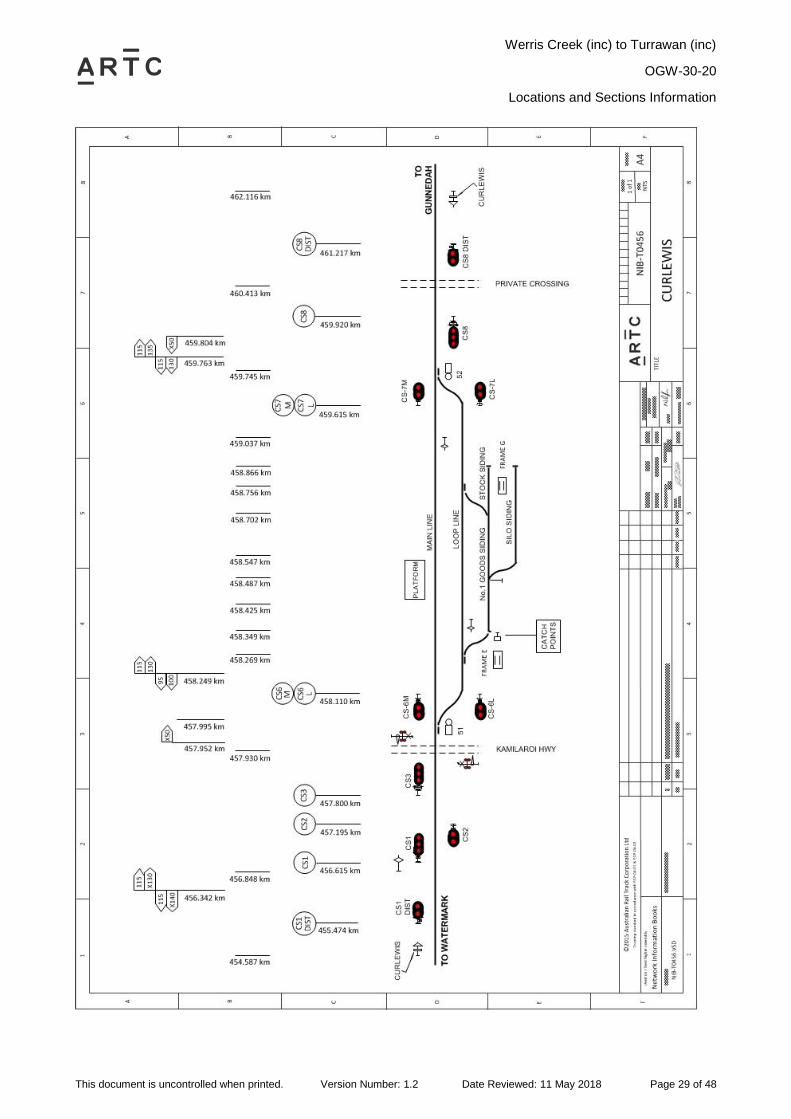
2.5 Curlewis (CLS)
General Arrangements
Curlewis is a Rail Vehicle Detection location controlled from Network Control Centre North.
Loop length 1490 metres
Passenger platform is located on the mainline.
Operation of Points and Signals
The points and signals at Curlewis are power operated and controlled by track circuit and cannot
be moved unless the track indicator diagram is showing that the track(s) controlling the points is
unoccupied.
Ground Frames
Frame E
Frame E is located on the Up side of the main line adjacent to the crossover and provides access
to No. 1 siding.
Frame E is unlocked by releasing switch from the Network Controller NCCN.
Frame G
Frame G is located on the Up side between the Silo Siding and the Stock Siding adjacent to the
crossover and provides access from No.1 Goods Siding to the Loop Line.
Frame G is unlocked by releasing switch from the Network Controller NCCN.
Kamilaroi Highway (Quirindi – Narrabri Road) Level Crossing
Type F flashing lights and bells, half-boom barriers and pedestrian boom barriers are provided at
the Kamilaroi Highway (Quirindi – Narrabri Road) level crossing at 457.930 km.
The warning equipment is automatically controlled by track circuit for Down and Up trains subject
to the clearance of the signals on either side of the level crossing, and manually controlled by an
operator‟s pushbutton unit for trains shunting the Loop line and No. 1 siding.
If a train closely approaches Up starting signal No. 7 or Down home signal No. 2, the setting of
the applicable signal route will cause the level crossing warning indicators to be displayed, but
clearing of the signals will be delayed for 15 seconds.
If it becomes necessary to hold a train at signal No. 7 or No. 2 after the signal has been cleared,
the level crossing warning indicators will continue to be displayed for a period of 120 seconds
after the signal is returned to stop, and will then cancel automatically.
Operator’s Pushbutton Unit for the Level Crossing
An operator‟s pushbutton unit is provided in a box inscribed "Shunter's switch" and attached to a
post located near frame C.
When a shunting movement will be required to obstruct the level crossing, before hand-signalling
the train over the level crossing, the Qualified Worker controlling the shunt must unlock the
operator‟s pushbutton unit and depress the "Start" pushbutton for one second to cause the
warning equipment to operate.
The warning indications must be cancelled manually when the rear of the shunting movement has
cleared the level crossing.

Werris Creek (inc) to Turrawan (inc)
OGW-30-20
Locations and Sections Information
This document is uncontrolled when printed. Version Number: 1.2 Date Reviewed: 11 May 2018 Page 28 of 48
If the movement is not proceeded with, the warning indications must be cancelled by pressing the
"Cancel" pushbutton in the operator‟s pushbutton unit for one second.
The operator‟s pushbutton unit must be kept closed and secured by an SL lock when not in use.
Werris Creek (inc) to Turrawan (inc)
OGW-30-20
Locations and Sections Information
This document is uncontrolled when printed. Version Number: 1.2 Date Reviewed: 11 May 2018 Page 29 of 48
Werris Creek (inc) to Turrawan (inc)
OGW-30-20
Locations and Sections Information
This document is uncontrolled when printed. Version Number: 1.2 Date Reviewed: 11 May 2018 Page 30 of 48
2.6 Gunnedah (GDH)
General Arrangements
Gunnedah is a Rail Vehicle Detection location controlled from Network Control Centre North.
Loop line South: 250 metres (platform road)
Loop line North: 1360 metres
Passenger station is located on Loop line South.
Yard Limits
In the Up direction, yard limits are GH26 to Shunt Limit board at 474.745km
In the down direction, yard limits are GH 1 to GH 26.
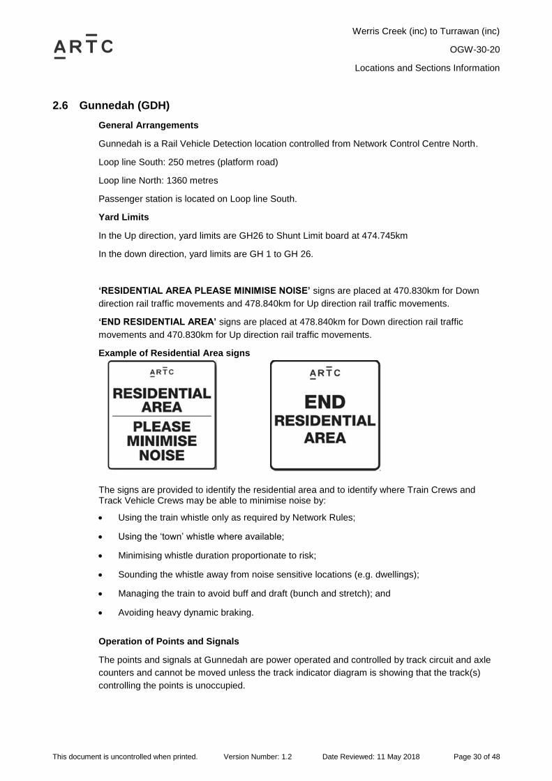
‘RESIDENTIAL AREA PLEASE MINIMISE NOISE’ signs are placed at 470.830km for Down
direction rail traffic movements and 478.840km for Up direction rail traffic movements.
‘END RESIDENTIAL AREA’ signs are placed at 478.840km for Down direction rail traffic
movements and 470.830km for Up direction rail traffic movements.
Example of Residential Area signs
The signs are provided to identify the residential area and to identify where Train Crews and Track Vehicle Crews may be able to minimise noise by:
Using the train whistle only as required by Network Rules;
Using the „town‟ whistle where available;
Minimising whistle duration proportionate to risk;
Sounding the whistle away from noise sensitive locations (e.g. dwellings);
Managing the train to avoid buff and draft (bunch and stretch); and
Avoiding heavy dynamic braking.
Operation of Points and Signals
The points and signals at Gunnedah are power operated and controlled by track circuit and axle
counters and cannot be moved unless the track indicator diagram is showing that the track(s)
controlling the points is unoccupied.
Werris Creek (inc) to Turrawan (inc)
OGW-30-20
Locations and Sections Information
This document is uncontrolled when printed. Version Number: 1.2 Date Reviewed: 11 May 2018 Page 31 of 48
Manildra Sidings, Goods Sidings and Loop Line
Shunting between the Manildra Sidings and Loop Line South can only commence when No.68
release has been given by the Network Controller and the release key has been taken by the
shunter. The release key will allow the operation of Frame K. To ensure that 48 points are not
inadvertently operated while non-signalling shunting movements occur, No.68 release will lock
and detect 48A / B points normal, but will not automatically call the points from the reverse
position. All main and shunt class routes that read over 48 points reverse will be required normal
before No.68 release can be given and will be locked when No.68 release is reversed, meaning
that the release must be restored before any signalling movements onto the Main Line through 48
points can occur. Refer safety interface agreement IA2215 for further details on Manildra sidings.
Shunting between the Goods Sidings and Loop Line South can only commence when No.69
release has been given by the Network Controller and the release key has been taken by the
shunter. The release key will allow the operation of Frame F. To ensure that 50 points are not
inadvertently operated while non-signalling shunting movements occur, No.69 release will lock
and detect 50A / B points normal, but will not automatically call the points from the reverse
position. All main and shunt class routes that read over 50 crossover reverse will be required
normal before No.69 release can be given and will be locked when No.69 release is reversed,
meaning that the release must be restored before any signalling movements onto the Main Line
through 50 points can occur.
Movements over 50A points will be only the authority of GH7 signal and 50A points indicator. The
signals will display a white arrow automatically when No 69 release is taken and levers 1F and 2F
(catch points) have been reversed with 50 points in the normal position.
Catch points (48B) on the Sydney end of the Loop Line provide protection for the Main Line from
unauthorised movements. The catch points are to be used for trapping protection only and not as
an overlap.
The Loop Line South may be used for the stabling of Manildra train unattended on arrival
overnight. However, the Loop Line South must not be used for the storage of wagons during the
day. Number 48 and 50 crossover must be placed in the normal position. Catch points (48B) are
provided on the Sydney end of the Loop Line South to protect the Main Line from unauthorised
movements from the Loop Line South.
Ground Frames
Frame K
Frame K is located on the Up side of the Main Line adjacent to the crossovers and provides
access to the Manildra Group Mill Sidings.
Frame K is unlocked by a key from releasing switch K which is located adjacent to frame K.
Releasing switch K is electrically released by No 68 release from Network Control Centre North.
Frame F
Frame F is located on the Up side of the Loop Line adjacent to catch points and provides
protection to the Loop Line from unauthorised movement from the Goods sidings.
Frame F is unlocked by a key from releasing switch F which is located adjacent to frame F.
Releasing switch F is electrically released by No 69 release from Network Control Centre North.
Werris Creek (inc) to Turrawan (inc)
OGW-30-20
Locations and Sections Information
This document is uncontrolled when printed. Version Number: 1.2 Date Reviewed: 11 May 2018 Page 32 of 48
Grain Siding
Shunting operations can only commence when 49, 51 and 52 points are set normal and No 70
release given by the Network Controller. This will enable the release key to be taken from the
releasing switch by the qualified worker / shunter. The release key (loose key) will enable
shunting operations to take place. The key shall be carried by the qualified worker / shunter in
control of the shunt movement. To ensure that 49, 51 and 52 points are not operated while non-
signalled shunting movements within the Grain Siding are taking place, No 70 release will lock
49, 51 and 52 points in the normal position. No 70 release, when given, will lock normal all routes
onto the Main Line from the Grain Siding and all routes into the Grain Siding from the Main Line.
The release must be restored before any signalled movements from the Grain Siding to the Main
Line or to the Grain Siding from the Main Line can occur.
Shunting operations into the Shunting Neck or Loco Roads can also commence when 8(S)B or
11(S)A routes are cleared by the Network Controller from signals GH8 and GH11 respectively. To
ensure that opposing non-signalled movements are not authorised during these operations, the
routes 8(S)B and 11(S)A will both require and lock 70 release normal.
Movements over 52A and 51B points will be on the authority of signals GH 11 and GH 10
respectively. The signals will display a white arrow automatically when No 70 release is given
with 51 and 52 points locked in the normal position.
Movements over 49B points will be on the authority of GH 8 signal and 49B points indicator. The
signals will display a white arrow automatically when No 70 release is given, with 49 points locked
in the normal position.
Carroll Street Level Crossing
Type F flashing lights and bells are provided at Carroll Street level crossing at 474.166 km.
Failure of Signals Protecting the Carroll Street Level Crossing
In the event of failure of the signals protecting the active level crossing at Carroll Street level
crossings, or if rail traffic is authorised to p ass the protecting signals in the STOP position, rail
traffic crews will be required to activate the level crossing warning equipment by operating the
push buttons provided on the level crossing hut before passing the protecting signals in the STOP
position.
Ensure that the level crossing roadside flashing lights and audible warning devices have activated
and the crossing is clear of road and pedestrian traffic.
Proceed past the signal at stop in accordance with ARTC Network Rule ANSG 608 Passing
Signals at STOP.
Marquis Street and New Street Level Crossings
Type F flashing lights, bells, half boom barriers, active pedestrian warning and pedestrian swing
gates are provided at Marquis Street level crossing at 475.476 km. Type F flashing lights and
bells are provided at New Street level crossing at 476.330 km.
To prevent the unnecessary operation of Marquis Street and New Street level crossings, level
crossing operation is not initiated when rail traffic approaches GH 2, GH 3, GH 4, GH 13 or GH
14 signals at STOP.
Failure of Signals Protecting the Marquis Street and New Street Level Crossings
In the event of failure of the signals protecting the active level crossing at Marquis Street or New
Street level crossings, or if rail traffic is authorised to pass the protecting signals in the STOP
Werris Creek (inc) to Turrawan (inc)
OGW-30-20
Locations and Sections Information
This document is uncontrolled when printed. Version Number: 1.2 Date Reviewed: 11 May 2018 Page 33 of 48
position, rail traffic crews will be required to activate the level crossing warning equipment by
operating the push buttons provided on the level crossing hut before passing the protecting
signals in the STOP position.
Advisory signs are located adjacent to the protecting signals stating:
BEFORE PASSING SIGNAL AT STOP PRESS BUTTON TO ACTIVATE LEVEL CROSSING
WARNING. BEFORE PASSING OVER LEVEL CROSSING ENSURE IT IS OPERATING
Signals Protecting the Level Crossings
Signal Km Line Level Crossing
GH 2 475.496 Main Marquis Street
GH 3 475.351 Main Marquis Street
GH 13 476.307 Main New Street
GH 14 476.441 Main New Street
Operation of Push Buttons on Protecting Signals
Press the push button on the signal and provided the operation is successful, a white light will be
displayed.
Ensure that the level crossing roadside flashing lights and audible warning devices have activated
and the crossing is clear of road and pedestrian traffic.
Proceed past the signal at stop in accordance with ARTC Network Rule ANSG 608 Passing
Signals at STOP.
Note: Rail Traffic Crews must obtain the appropriate authority from the relevant Network
Controller before passing signals at STOP.
2.6.1 Ground Frames Stock & Wheat Sidings
Frames L and M
Frames L and M are located on the Down side of the Main Line adjacent to the crossovers and
provide access to the Stock sidings.
Frame L is unlocked by a key from releasing switch L which is located adjacent to frame L.
Releasing switch L is electrically released by No 71 release from Network Control Centre North.
Frame M is unlocked by a key from releasing switch M, N which is located midway between M &
N frames, up side. Releasing switch M is electrically released by No 71 release from Network
Control Centre North.
Frame N
Frame N is located on the Down side of the Main Line adjacent to the crossovers and provides
access to the Wheat sidings.
Frame N is unlocked by a key from releasing switch M, N which is located midway between M &
N frames, up side. Releasing switch N is electrically released by No 71 release from Network
Control Centre North.
Note: Frames M & N are unlocked by the one key.
Werris Creek (inc) to Turrawan (inc)
OGW-30-20
Locations and Sections Information
This document is uncontrolled when printed. Version Number: 1.2 Date Reviewed: 11 May 2018 Page 34 of 48
2.6.2 Working Arrangements for the Gunnedah Coal Loop
Entry to and exit from the Gunnedah Coal Loop is remotely controlled by the Network Controller
from the Network Control Centre North.
Only one 1340m train fits in this balloon loop.
Rail Traffic Entering the Gunnedah Coal Loop
The train must proceed through Gunnedah Yard according to the signals provided. The ARTC
Network Controller will set the route and signal will display a yellow subsidiary shunt indication for
entry into the Gunnedah Coal Loop
Rail Traffic Departing the Gunnedah Coal Loop
When arriving at the stop sign, the driver will contact the ARTC Network Controller at the Network
Control Centre North Broadmeadow and request authority to depart. The Network Controller will
reverse the main line points and clear the signal. The train will then proceed onto the Main Line
and continue on the authority of fixed signals.
Refer safety interface agreement IA2214 for further details.

Werris Creek (inc) to Turrawan (inc)
OGW-30-20
Locations and Sections Information
This document is uncontrolled when printed. Version Number: 1.2 Date Reviewed: 11 May 2018 Page 35 of 48
Werris Creek (inc) to Turrawan (inc)
OGW-30-20
Locations and Sections Information
This document is uncontrolled when printed. Version Number: 1.2 Date Reviewed: 11 May 2018 Page 36 of 48
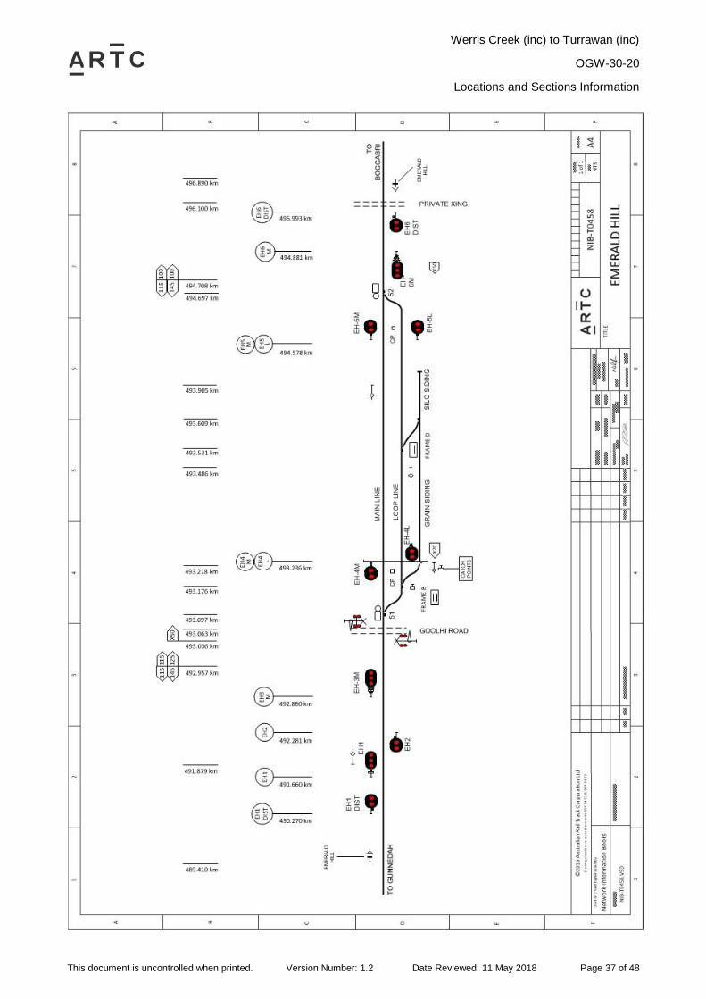
2.7 Emerald Hill (EHI)
General Arrangements
Emerald Hill is a Rail Vehicle Detection location controlled from Network Control Centre North.
Loop length 1337 metres
Refer safety interface agreement IA1523 for details of loading operations at this location.
Operation of Points and Signals
The points and signals at Emerald Hill are power operated and controlled by track circuit and
cannot be moved unless the track indicator diagram is showing that the track(s) controlling the
points is unoccupied.
Goohli Road (Gunnedah Road) Level Crossing
Type F flashing lights, bells, half boom barriers, are provided at Goohli Road level crossing at
493.063 km.
To prevent the unnecessary operation of Goohli Road level crossing, level crossing operation is
not initiated when rail traffic approaches EH 3, EH 4M, or EH 4L signals at Stop.
Failure of Signals Protecting the Goohli Road Level Crossing
In the event of failure of the signals protecting the active level crossing at Goohli Road level
crossing, or if rail traffic is authorised to pass the protecting signals in the STOP position, rail
traffic crews will be required to activate the level crossing warning equipment by operating the
push buttons provided on the level crossing hut before passing the protecting signals in the STOP
position.
Ground Frames
Frame B
Frame B is located on the Up side of the Loop line adjacent to the crossover and provides access
to the Grain siding.
Frame B is unlocked by releasing switch from Network Controller NCCN.
Frame D
Frame D is located on the Up side of the Loop line adjacent to the crossover and provides access
to the Silo siding.
Frame D is unlocked by releasing switch from Network Controller NCCN.
Werris Creek (inc) to Turrawan (inc)
OGW-30-20
Locations and Sections Information
This document is uncontrolled when printed. Version Number: 1.2 Date Reviewed: 11 May 2018 Page 37 of 48
Werris Creek (inc) to Turrawan (inc)
OGW-30-20
Locations and Sections Information
This document is uncontrolled when printed. Version Number: 1.2 Date Reviewed: 11 May 2018 Page 38 of 48
2.8 Boggabri (BOG)
General Arrangements
Boggabri is a Rail Vehicle Detection location controlled from Network Control Centre North.
It is a consolidated location incorporating Boggabri, Boggabri Maules Creek branch, and Boggabri
Coal loop.
Loop length 1377 metres
Passenger station is located on the mainline.
Yard Limits
Boggabri yard limits extend from BI 1 to BC 8 signals.
Operation of Points and Signals
All points worked from the Network Control Centre North are controlled by track circuit / axle
counter and cannot be moved unless the track indicator diagram is showing the track(s)
controlling the points is unoccupied.
Ground Frames
Frame F is located on the down side of the main line and provides access to the sleeper siding.
Release is obtained from the Network Controller NCCN.
2.8.1 Boggabri Maules Creek Branch Line
Entry to and exit from the Boggabri Maules Creek branch line is remotely controlled by the
Network Controller from the Network Control Centre North. Further details on the branch line are
included in safety interface agreement IA2203.
Rail Traffic departing the Maules Creek Coal & Boggabri Coal East Balloon Loops
When arriving at the departure signal and train loading is completed the driver will contact the
ARTC Network Controller at the Network Control Centre North and request authority to depart.
When authorised to proceed, the Network Controller will clear the applicable signal. The train will
then proceed onto the branch line and continue on the authority of fixed signals.
Note: Boggabri Maules Creek branch line is a private siding. Rail movements on the branch
lines to Maules Creek Coal and Boggabri Coal East Balloon Loops is remotely
controlled by the Network Controller from Network Control Centre North. The rail
operation within the Maules Creek Coal and Boggabri Coal East Balloon Loops are
managed by the respective producers / owner of the load-out terminals. Both of these
balloon loops hold at least one 1340m loaded train and two 1340m rakes on the
approach side of the load point.
Special instruction for isolating the points leading to Boggabri Maules Creek branch line
for maintenance purposes
To prevent access to the Boggabri Maules Creek Branch line during maintenance work within the
branch lines, special key-locked isolating switches are provided in a locked box to enable the
power for No 51 points providing access from the main line to Boggabri Maules Creek Branch line
to be isolated.
Number 51 points to the Boggabri Maules Creek Branch line must be set in the normal position
for main line rail traffic movements prior to the maintenance isolation switch being operated.
Werris Creek (inc) to Turrawan (inc)
OGW-30-20
Locations and Sections Information
This document is uncontrolled when printed. Version Number: 1.2 Date Reviewed: 11 May 2018 Page 39 of 48
Special instruction for isolating the points leading to Maules Creek branch line or
Boggabri East branch line for maintenance purposes
To prevent access to the either of the mine branches during maintenance work within the branch
lines, special key-locked isolating switches are provided in a locked box to enable the power for
No 55 points providing access from the branch line to the individual coal loop branches to be
isolated.
Number 55 points must be set in the position for the other coal loop prior to the maintenance
isolation switch being operated. For example, to isolate the Maules Creek coal branch, 55 points
must be set to the Boggabri East coal branch before the isolation switch is operated. An
indication appears on the Network Controllers Phoenix panel to show that the maintenance
switch has been operated.
Boggabri Coal Maules Creek Coal Branch Line Level Crossing at 528.293km and Boggabri
Coal Branch Line Level Crossing at 528.270km.
Type F flashing lights, bells, half boom barriers, active warning is provided at Boggabri Coal
access road, Maules Creek Coal Branch Line Level Crossing at 528.293km and Boggabri Coal
Branch Line Level Crossing at 528.270km.
To prevent the unnecessary operation of Boggabri Coal access road level crossings, level
crossing operation is not initiated when rail traffic approaches BC12, BC14 signals at stop.
Failure of Signals Protecting the Boggabri Access Road Level Crossing
In the event of failure of the signals protecting the active level crossing at the Boggabri Access
Road, or if rail traffic is authorised to pass the protecting signals in the Stop position, rail traffic
crews will be required to activate the level crossing warning equipment by operating the push
buttons provided on the level crossing hut before passing the protecting signals in the STOP
position.
2.8.2 Boggabri Coal Balloon Loop
Entry to and exit from the Boggabri Coal Loop is remotely controlled by the Network Controller
from the Network Control Centre North.
When arriving at the departure signal and train loading is completed the driver will contact the
ARTC Network Controller at the Network Control Centre North and request authority to depart.
When authorised to proceed, the Network Controller will clear the applicable signal. The train will
then proceed onto the main line and continue on the authority of fixed signals.
Note: Boggabri Coal is a private siding, the rail operations within Boggabri Coal Balloon loop
is managed by the producer / owner of the load-out terminals. Only one 1340m coal
train fits in this loop, and requires access to the mainline to complete loading.
Refer safety interface agreement IA2204 for further details.
Werris Creek (inc) to Turrawan (inc)
OGW-30-20
Locations and Sections Information
This document is uncontrolled when printed. Version Number: 1.2 Date Reviewed: 11 May 2018 Page 40 of 48
Werris Creek (inc) to Turrawan (inc)
OGW-30-20
Locations and Sections Information
This document is uncontrolled when printed. Version Number: 1.2 Date Reviewed: 11 May 2018 Page 41 of 48

Werris Creek (inc) to Turrawan (inc)
OGW-30-20
Locations and Sections Information
This document is uncontrolled when printed. Version Number: 1.2 Date Reviewed: 11 May 2018 Page 42 of 48
Werris Creek (inc) to Turrawan (inc)
OGW-30-20
Locations and Sections Information
This document is uncontrolled when printed. Version Number: 1.2 Date Reviewed: 11 May 2018 Page 43 of 48
2.9 Baan Baa (BAA)
General Arrangements
Baan Baa is a silo siding located in the Boggabri to Narrabri Coal section.
Siding length: 402 metres
Safeworking
Note: If a train or track vehicle has locked away in the siding, a Special Proceed Authority
(SPA) or TOA is needed to shunt or depart Baan Baa.
Train crew shunting Baan Baa should take both frame keys at the start of shunting, and not return
either key until all shunting work is complete. Returning either key will lock up the interlocking,
and may require the train to depart the section to rectify.
Ground Frames
Frame E
Frame E is located on the Down side of the main line adjacent to the points and provides access
to No. 2 siding.
Frame E is unlocked by releasing switch from Network Controller NCCN.
Frame F
Frame F is located on the Down side of the main line adjacent to the points and provides access
to No. 2 siding.
Frame F is unlocked by releasing switch from Network Controller NCCN.
Operator’s Pushbutton Unit for the Level Crossing
An operator‟s pushbutton unit is provided in a box inscribed "Shunter's switch" and attached to a
post located near Frame E.
When a shunting movement will be required to obstruct the level crossing, before hand-signalling
the train over the level crossing, the Qualified Worker controlling the shunt must unlock the
operator‟s pushbutton unit and depress the "Start" pushbutton for one second to cause the
warning equipment to operate.
The warning indications must be cancelled manually when the rear of the shunting movement has
cleared the level crossing.
If the movement is not proceeded with, the warning indications must be cancelled by pressing the
"Cancel" pushbutton in the operator‟s pushbutton unit for one second.
The operator‟s pushbutton unit must be kept closed and secured by an SL lock when not in use.

Werris Creek (inc) to Turrawan (inc)
OGW-30-20
Locations and Sections Information
This document is uncontrolled when printed. Version Number: 1.2 Date Reviewed: 11 May 2018 Page 44 of 48
Werris Creek (inc) to Turrawan (inc)
OGW-30-20
Locations and Sections Information
This document is uncontrolled when printed. Version Number: 1.2 Date Reviewed: 11 May 2018 Page 45 of 48
2.10 Narrabri Coal (NCL)
Narrabri Coal is a Rail Vehicle Detection location controlled from Network Control Centre North.
It is a private coal balloon loop.
Entry to and exit from the Narrabri Coal Loop is remotely controlled by the Network Controller
from the Network Control Centre North.
When arriving at the departure signal and train loading is completed the driver will contact the
ARTC Network Controller at the Network Control Centre North and request authority to depart.
When authorised to proceed, the Network Controller will clear the applicable signal. The train will
then proceed onto the main line and continue on the authority of fixed signals.
Note: Narrabri Coal is a private siding. The rail operations within the Narrabri Coal Balloon
loop are managed by the producer/owner of the load-out terminals. A second 1340m
coal train fits in this loop once the first has completed loading.
Refer safety interface agreement IA2221 for further details.

Werris Creek (inc) to Turrawan (inc)
OGW-30-20
Locations and Sections Information
This document is uncontrolled when printed. Version Number: 1.2 Date Reviewed: 11 May 2018 Page 46 of 48
Werris Creek (inc) to Turrawan (inc)
OGW-30-20
Locations and Sections Information
This document is uncontrolled when printed. Version Number: 1.2 Date Reviewed: 11 May 2018 Page 47 of 48
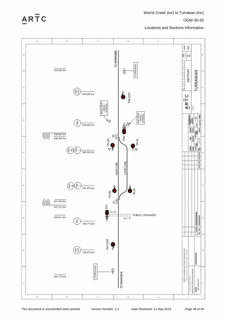
2.11 Turrawan (TWN)
General Arrangements
Turrawan is a Rail Vehicle Detection location controlled from Network Control Centre North.
Train control north of Turrawan is by Train Order Working.
Loop length 1080 metres
Operation of Points and Signals
All points worked from the Network Control Centre North are controlled by track circuit/axle
counter and cannot be moved unless the track indicator diagram is showing the track(s)
controlling the points is unoccupied.
Once the driver has obtained a Train Order (or Proceed Authority) from train Order Control, the
driver must notify NCCN North Board Network Controller of the order/authority number, and the
Network Controller should then clear the relevant MLI.
Main Line Indicators TN 3M and TN 3L will indicate with a pulsating white light, when the road is
cleared for departure into Train Order Territory. On TN 3M and TN 3L there are signs stating:
„DO NOT PROCEED UNLESS IN POSSESSION OF A TRAIN ORDER‟
Begin and End Train Order Working signs are located at 548.694km.
Werris Creek (inc) to Turrawan (inc)
OGW-30-20
Locations and Sections Information
This document is uncontrolled when printed. Version Number: 1.2 Date Reviewed: 11 May 2018 Page 48 of 48