network force/torque sensor system - ati industrial … ft.pdf · network . force/torque sensor...
TRANSCRIPT
Engineered Products for Robotic ProductivityPinnacle Park • 1031 Goodworth Drive • Apex, NC 27539 • Tel: 919.772.0115 • Fax: 919.772.8259 • www.ati-ia.com • Email: [email protected]
Net F/T
Network Force/Torque Sensor System
Manual
Document #: 9620-05-NET FT
Manual, FT, Net FTDocument #9620-05-NET FT-13
Pinnacle Park • 1031 Goodworth Drive • Apex, NC 27539 • Tel: 919.772.0115 • Fax: 919.772.8259 • www.ati-ia.com • Email: [email protected] B-2
ForewordInformation contained in this document is the property of ATI Industrial Automation, Inc. and shall not be reproduced in whole or in part without prior written approval of ATI Industrial Automation, Inc. The information herein is subject to change without notice and should not be construed as a commitment on the part of ATI Industrial Automation, Inc. This manual is periodically revised to reflect and incorporate changes made to the F/T system.
ATI Industrial Automation, Inc. assumes no responsibility for any errors or omissions in this document. Users’ critical evaluation is welcome to assist in the preparation of future.
Copyright © by ATI Industrial Automation, Inc., Apex, North Carolina USA. All Rights Reserved. Published in the USA.
In consideration that ATI Industrial Automation, Inc. (ATI) products are intended for use with robotic and/or automated machines, ATI does not recommend the use of its products for applications wherein failure or malfunction of a ATI component or system threatens life or makes injury probable. Anyone who uses or incorporates ATI components within any potentially life threatening system must obtain ATI’s prior consent based upon assurance to ATI that a malfunction of ATI’s component does not pose direct or indirect threat of injury or death, and (even if such consent is given) shall indemnify ATI from any claim, loss, liability, and related expenses arising from any injury or death resulting from use of ATI components.
All trademarks belong to their respective owners. Windows and Excel are registered trademarks of Microsoft Corporation. Ipad is a registered trademark of Apple Inc.
FCC Compliance - Class A
This device complies with Part 15 Subpart B of the FCC Title 47. Operation is subject to the following two conditions: (1) this device may not cause harmful interference, and (2) this device must accept any interference received, including interference that may cause undesired operation.
Any modifications to the device could impact compliance. It is the user’s responsibility to certify the device remains compliant after modifications
“ Electromagnetic Compatibility”
This device complies with EMC Directive 2004/108/EC and conforms to the following standards: EN55022:1998+A1:2000 +A2:2003, EN61000-4-2:1995 +A1:1998+A2:2001, EN61000-4-3:2002, EN61000-4-4:2004, EN61000-4-5:1995 +A1:1996, EN61000-4-6:1996 +A1:2001, EN61000-4-8:1995, EN61000-4-11:2001.
Manual, FT, Net FTDocument #9620-05-NET FT-13
Pinnacle Park • 1031 Goodworth Drive • Apex, NC 27539 • Tel: 919.772.0115 • Fax: 919.772.8259 • www.ati-ia.com • Email: [email protected] B-3
Note
Please read the manual before calling customer service. Before calling, have the following information available:
1. Serial number (e.g., FT01234)
2. Transducer model (e.g., Nano17, Gamma, Theta, etc.)
3. Calibration (e.g., US-15-50, SI-65-6, etc.)
4. Accurate and complete description of the question or problem
5. Computer and software information. Operating system, PC type, drivers, application software, and other relevant information about your configuration.
If possible, be near the F/T system when calling.
How to Reach Us
Sale, Service and Information about ATI products:
ATI Industrial Automation 1031 Goodworth Drive Apex, NC 27539 USA www.ati-ia.com Tel: +1.919.772.0115 Fax: +1.919.772.8259 E-mail: [email protected]
Technical support and questions:Application Engineering Tel: +1.919.772.0115, Option 2, Option 2 Fax: +1.919.772.8259 E-mail: [email protected]
Manual, FT, Net FTDocument #9620-05-NET FT-13
Pinnacle Park • 1031 Goodworth Drive • Apex, NC 27539 • Tel: 919.772.0115 • Fax: 919.772.8259 • www.ati-ia.com • Email: [email protected] B-4
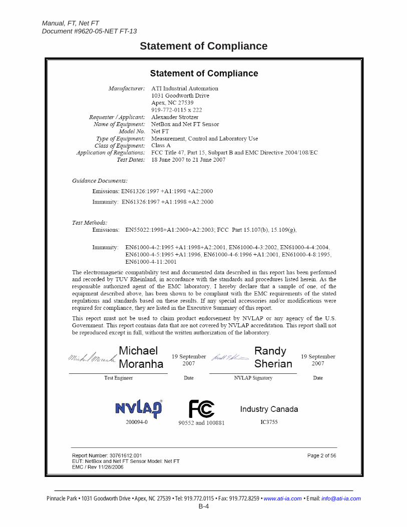
Statement of Compliance
Manual, FT, Net FTDocument #9620-05-NET FT-13
Pinnacle Park • 1031 Goodworth Drive • Apex, NC 27539 • Tel: 919.772.0115 • Fax: 919.772.8259 • www.ati-ia.com • Email: [email protected] B-5
Table of ContentsForeword .......................................................................................................................................B-2Statement of Compliance ............................................................................................................B-4Glossary ......................................................................................................................................B-101. Safety ....................................................................................................................................B-12
1.1 ExplanationofNotifications ................................................................................................... B-12
1.2 General Safety Guidelines ...................................................................................................... B-12
1.3 Safety Precautions .................................................................................................................. B-12
2. System Overview .................................................................................................................B-132.1 Multiple Calibrations ............................................................................................................... B-13
2.2 MultipleConfigurations .......................................................................................................... B-13
2.3 Force and Torque Values ........................................................................................................ B-13
2.4 System Status Code ................................................................................................................ B-13
2.5 Thresholding ............................................................................................................................ B-13
2.6 Tool Transformations .............................................................................................................. B-13
2.7 Multiple Interfaces ................................................................................................................... B-13
2.8 Power Supply ........................................................................................................................... B-13
3. GettingStarted ....................................................................................................................B-143.1 Unpacking ................................................................................................................................ B-14
3.2 System Components Description .......................................................................................... B-143.2.1 F/T Transducer ..............................................................................................................B-15
3.2.2 Transducer Cable ..........................................................................................................B-16
3.2.3 Net Box ..........................................................................................................................B-16
3.3 ConnectingtheSystemComponents ................................................................................... B-173.3.1 Connecting the Transducer to the Net Box ...................................................................B-17
3.3.2 Providing Power to the Net F/T .....................................................................................B-173.3.2.1 Method 1: Providing Power with PoE ............................................................B-173.3.2.2 Method 2: Providing Power to Pwr/CAN Input ...............................................B-18
3.3.3 Connecting to Ethernet ..................................................................................................B-193.3.3.1 Option 1: Connect to an Ethernet Network ....................................................B-203.3.3.2 Option 2: Connect directly to a Computer’s Ethernet Interface .....................B-20
3.4 IPAddressConfigurationforEthernet .................................................................................. B-21
3.5 ConnectingtoEthernetusingaWindowsComputer .......................................................... B-223.5.1 Windows Vista and Windows 7 .....................................................................................B-22
3.5.2 Windows XP ..................................................................................................................B-23
3.6 ConnectingtoanEthernet-basedFieldbus .......................................................................... B-25
3.7 ConnectingtoDeviceNet(usingDeviceNet-CompatibilityMode) ...................................... B-25

Manual, FT, Net FTDocument #9620-05-NET FT-13
Pinnacle Park • 1031 Goodworth Drive • Apex, NC 27539 • Tel: 919.772.0115 • Fax: 919.772.8259 • www.ati-ia.com • Email: [email protected] B-6
3.8 ConnectingtheNetBoxtoaCANBusNetwork .................................................................. B-25
3.9 DIP Switches and Termination Resistor ................................................................................ B-253.9.1 Termination Resistor ......................................................................................................B-26
3.9.2 Node Address ................................................................................................................B-26
3.9.3 Baud Rate .....................................................................................................................B-28
3.10 Baud Rate ................................................................................................................................. B-28
3.11 Power-Up Cycle ....................................................................................................................... B-29
4. WebPages ...........................................................................................................................B-314.1 WelcomePage(index.htm) ..................................................................................................... B-31
4.2 SnapshotPage(rundata.htm) ................................................................................................ B-32
4.3 DemoPage(demo.htm) .......................................................................................................... B-34
4.4 SettingsPage(setting.htm) .................................................................................................... B-35
4.5 ThresholdingPage(moncon.htm) ......................................................................................... B-364.5.1 Threshold Relay ............................................................................................................B-38
4.5.1.1 Standard Net Box Threshold Relay ...............................................................B-384.5.1.2 Fieldbus Net Box and Optional Solid State Threshold Relay.........................B-40
4.6 ConfigurationsPage(config.htm) ......................................................................................... B-42
4.7 CommunicationSettingsPage(comm.htm) ......................................................................... B-464.7.1 TCP Modbus Register Map ...........................................................................................B-50
4.8 SystemInformationPage(manuf.htm) ................................................................................. B-51
4.9 ATIWebSiteMenuItem .......................................................................................................... B-51
5. Java Demo Application .......................................................................................................B-525.1 StartingtheDemo ................................................................................................................... B-52
5.2 Data Display with the Demo ................................................................................................... B-53
5.3 CollectingDatawiththeDemo ............................................................................................... B-54
5.4 The Errors Display of the Demo ............................................................................................. B-56
5.5 DevelopingYourOwnJavaApplication ................................................................................ B-57
6. NetF/TConfigurationUtility ...............................................................................................B-586.1 FindingNetF/TsontheNetwork ........................................................................................... B-58
6.2 BackingUpaConfigurationtoaComputer .......................................................................... B-60
6.3 RestoringaSavedConfiguration .......................................................................................... B-60
6.4 InspectingaSavedConfigurationFile .................................................................................. B-61
7. Net F/T iPad Application .....................................................................................................B-627.1 MonitoringandDataCollection ............................................................................................. B-62
7.2 ExportingData ......................................................................................................................... B-64
7.3 DataCollectionSettings ......................................................................................................... B-65
8. CommonGatewayInterface(CGI) .....................................................................................B-67
Manual, FT, Net FTDocument #9620-05-NET FT-13
Pinnacle Park • 1031 Goodworth Drive • Apex, NC 27539 • Tel: 919.772.0115 • Fax: 919.772.8259 • www.ati-ia.com • Email: [email protected] B-7
8.1 SettingsCGI(setting.cgi) ....................................................................................................... B-68
8.2 ThresholdingCGI(moncon.cgi) ............................................................................................. B-69
8.3 ConfigurationsCGI(config.cgi) ............................................................................................. B-69
8.4 CommunicationsCGI(comm.cgi) .......................................................................................... B-72
9. SystemSettingsXMLPages ..............................................................................................B-739.1 SystemandConfigurationInformation(netftapi2.xml) ....................................................... B-73
9.2 CalibrationInformation(netftcalapi.xml) .............................................................................. B-76
10. UDPInterfaceUsingRDT....................................................................................................B-7710.1 RDT Protocol ........................................................................................................................... B-77
10.2 Extended RDT Requests ......................................................................................................... B-79
10.3 CalculatingF/TValuesforRDT .............................................................................................. B-79
10.4 Multi-Unit Mode ....................................................................................................................... B-79
10.5 Multiple Clients ........................................................................................................................ B-79
10.6 Notes on UDP and RDT Mode ................................................................................................ B-80
10.7 Example Code .......................................................................................................................... B-80
11. TCP Interface .......................................................................................................................B-8011.1 General ..................................................................................................................................... B-80
11.2 Command Codes ..................................................................................................................... B-80
11.3 Read F/T Command ................................................................................................................. B-80
11.4 Read F/T Response ................................................................................................................. B-81
11.5 Read Calibration Info Command ............................................................................................ B-81
11.6 Read Calibration Info Response ............................................................................................ B-82
11.7 WriteToolTransformCommand ............................................................................................ B-82
11.8 WriteMonitorConditionCommand ....................................................................................... B-83
11.9 WriteResponse ....................................................................................................................... B-83
12. EtherNet/IP Operation .........................................................................................................B-8412.1 Overview .................................................................................................................................. B-84
12.2 ModuleandNetworkStatusLED ........................................................................................... B-84
13. DeviceNet-Compatibility Mode Operation .........................................................................B-8513.1 Overview .................................................................................................................................. B-85
13.2 MAC ID ...................................................................................................................................... B-85
13.3 Baud Rate ................................................................................................................................. B-85
13.4 ModuleandNetworkStatusLED ........................................................................................... B-85
13.5 EDS File .................................................................................................................................... B-85
14. EtherNet/IP and DeviceNet CIP Model ...............................................................................B-8614.1 Overview .................................................................................................................................. B-86
Manual, FT, Net FTDocument #9620-05-NET FT-13
Pinnacle Park • 1031 Goodworth Drive • Apex, NC 27539 • Tel: 919.772.0115 • Fax: 919.772.8259 • www.ati-ia.com • Email: [email protected] B-8
14.2 CalculatingF/TValuesforCIP ............................................................................................... B-8814.2.1 EtherNet/IP ....................................................................................................................B-88
14.2.2 DeviceNet .....................................................................................................................B-88
14.3 Object Model ............................................................................................................................ B-8914.3.1 Data Types ....................................................................................................................B-89
14.3.2 EtherNet/IP ....................................................................................................................B-89
14.3.3 Transducer Force/Torque Object (0x65—6 Instances) ..................................................B-90
14.3.4 Transducer Force/Torque Object (0x65—6 Instances) ..................................................B-90
14.3.5 System Status Object (0x67—1 Instance) ....................................................................B-91
14.3.6 ConfigurationsObject(0x71—16Instances) .................................................................B-91
14.3.7 Transducer Force/Torque Object (0x65—6 Instances) ..................................................B-92
14.3.8 Thresholding Settings Object (0x73—32 Instances) .....................................................B-93
15. CAN Bus Operation .............................................................................................................B-9415.1 Overview .................................................................................................................................. B-94
15.2 Protocol Description ............................................................................................................... B-94
15.3 Base Address and Communication Format .......................................................................... B-94
15.4 Baud Rate ................................................................................................................................. B-95
15.5 CalculatingF/TValuesforCAN .............................................................................................. B-95
16. Fieldbus Operation ..............................................................................................................B-9616.1 PROFINET Fieldbus Interface ................................................................................................ B-96
16.1.1 Enabling the PROFINET Interface ................................................................................B-97
16.1.2 Communications CGI (comm.cgi) Options ....................................................................B-99
16.1.3 XML Page Elements ......................................................................................................B-99
16.1.4 Returning Default Settings ............................................................................................B-99
16.1.5 Replacing and Installed PROFINET Fieldbus Net Box ...............................................B-10016.1.5.1 Replacing and Installed PROFINET Fieldbus Net Box ................................B-10016.1.5.2 Replacement with Previously Commissioned Fieldbus Net Box .................B-100
17. Advanced Topics ...............................................................................................................B-10117.1 ImprovingEthernetThroughput .......................................................................................... B-101
17.1.1 Direct Connection between Net F/T and Host .............................................................B-101
17.1.2 Choice of Operating System .......................................................................................B-101
17.1.3 Increasing Operating System Performance ................................................................B-101
17.1.4 Avoid Logging the Host to a Company Network ..........................................................B-101
17.1.5 Use a Dedicated Network ............................................................................................B-101
17.2 ReducingNoise ..................................................................................................................... B-10217.2.1 Mechanical Vibration ...................................................................................................B-102
17.2.2 Electrical Interference ..................................................................................................B-102
17.3 DetectingFailures(Diagnostics) ......................................................................................... B-102

Manual, FT, Net FTDocument #9620-05-NET FT-13
Pinnacle Park • 1031 Goodworth Drive • Apex, NC 27539 • Tel: 919.772.0115 • Fax: 919.772.8259 • www.ati-ia.com • Email: [email protected] B-9
17.3.1 Detecting Sensitivity Changes .....................................................................................B-102
17.4 Scheduled Maintenance ....................................................................................................... B-10217.4.1 Periodic Inspection ......................................................................................................B-102
17.5 AWordaboutResolution ..................................................................................................... B-103
17.6 ConnectingtoSpecificIndustrialRobots ........................................................................... B-10317.6.1 ABB Robotics ..............................................................................................................B-104
17.6.2 Denso Robotics ...........................................................................................................B-104
17.6.3 Fanuc Robotics ...........................................................................................................B-104
17.6.4 Kuka Robotics .............................................................................................................B-105
17.6.5 Motoman Robotics ......................................................................................................B-105
18. Troubleshooting ................................................................................................................B-10618.1 System Status Code .............................................................................................................. B-106
18.2 StatusWord ........................................................................................................................... B-108
18.3 Questions and Answers........................................................................................................ B-10918.3.1 Errors with Force and Torque Readings ......................................................................B-110
19. GeneralSpecifications ......................................................................................................B-11119.1 Environmental ........................................................................................................................B-111
19.1.1 Storage and Operating Temperatures ......................................................................... B-111
19.2 TransducerDataFiltering ......................................................................................................B-111
19.3 ElectricalSpecifications(PowerSupply) .............................................................................B-11319.3.1 Communications ..........................................................................................................B-113
19.3.1.1 Ethernet Interface ........................................................................................B-11319.3.1.2 CAN Interface ..............................................................................................B-114
19.3.2 Mating Connectors ......................................................................................................B-114
19.3.3 Standard Threshold Relay ...........................................................................................B-114
19.3.4 Solid-State Threshold Relay ........................................................................................B-114
19.3.5 NetBox Transducer Cabling ........................................................................................B-115
19.4 NetBoxWeight .......................................................................................................................B-115
20. Drawings ............................................................................................................................B-11620.1 9105-NETBDrawing ...............................................................................................................B-116
20.2 9105-NETBADrawing .............................................................................................................B-117
20.3 9105-NETB-PN2Drawing .......................................................................................................B-118
Manual, FT, Net FTDocument #9620-05-NET FT-13
Pinnacle Park • 1031 Goodworth Drive • Apex, NC 27539 • Tel: 919.772.0115 • Fax: 919.772.8259 • www.ati-ia.com • Email: [email protected] B-10
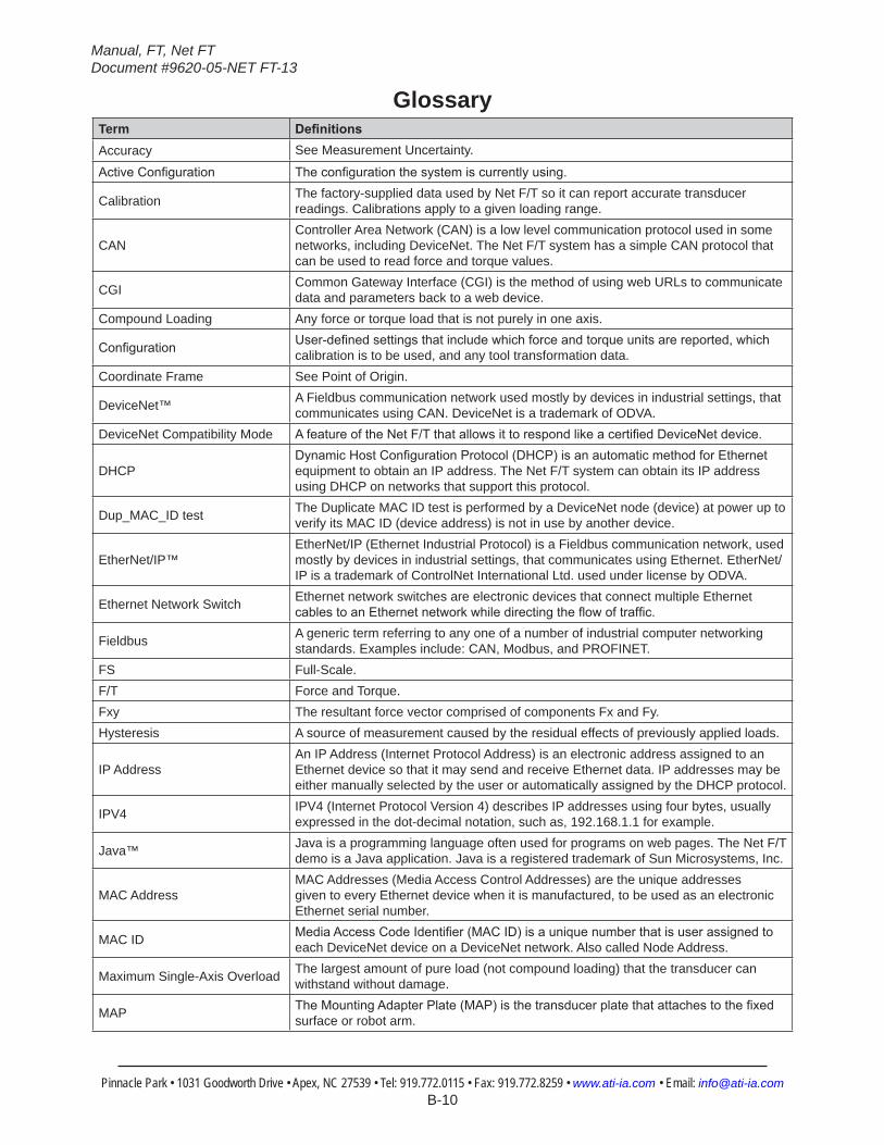
GlossaryTerm DefinitionsAccuracy See Measurement Uncertainty.
ActiveConfiguration Theconfigurationthesystemiscurrentlyusing.
Calibration The factory-supplied data used by Net F/T so it can report accurate transducer readings. Calibrations apply to a given loading range.
CANController Area Network (CAN) is a low level communication protocol used in some networks, including DeviceNet. The Net F/T system has a simple CAN protocol that can be used to read force and torque values.
CGI Common Gateway Interface (CGI) is the method of using web URLs to communicate data and parameters back to a web device.
Compound Loading Any force or torque load that is not purely in one axis.
Configuration User-definedsettingsthatincludewhichforceandtorqueunitsarereported,whichcalibration is to be used, and any tool transformation data.
Coordinate Frame See Point of Origin.
DeviceNet™ A Fieldbus communication network used mostly by devices in industrial settings, that communicates using CAN. DeviceNet is a trademark of ODVA.
DeviceNet Compatibility Mode AfeatureoftheNetF/TthatallowsittorespondlikeacertifiedDeviceNetdevice.
DHCPDynamicHostConfigurationProtocol(DHCP)isanautomaticmethodforEthernetequipment to obtain an IP address. The Net F/T system can obtain its IP address using DHCP on networks that support this protocol.
Dup_MAC_ID test The Duplicate MAC ID test is performed by a DeviceNet node (device) at power up to verify its MAC ID (device address) is not in use by another device.
EtherNet/IP™EtherNet/IP (Ethernet Industrial Protocol) is a Fieldbus communication network, used mostly by devices in industrial settings, that communicates using Ethernet. EtherNet/IP is a trademark of ControlNet International Ltd. used under license by ODVA.
Ethernet Network Switch Ethernet network switches are electronic devices that connect multiple Ethernet cablestoanEthernetnetworkwhiledirectingtheflowoftraffic.
Fieldbus A generic term referring to any one of a number of industrial computer networking standards. Examples include: CAN, Modbus, and PROFINET.
FS Full-Scale.F/T Force and Torque.Fxy The resultant force vector comprised of components Fx and Fy.Hysteresis A source of measurement caused by the residual effects of previously applied loads.
IP AddressAn IP Address (Internet Protocol Address) is an electronic address assigned to an Ethernet device so that it may send and receive Ethernet data. IP addresses may be either manually selected by the user or automatically assigned by the DHCP protocol.
IPV4 IPV4 (Internet Protocol Version 4) describes IP addresses using four bytes, usually expressed in the dot-decimal notation, such as, 192.168.1.1 for example.
Java™ Java is a programming language often used for programs on web pages. The Net F/T demo is a Java application. Java is a registered trademark of Sun Microsystems, Inc.
MAC AddressMAC Addresses (Media Access Control Addresses) are the unique addresses given to every Ethernet device when it is manufactured, to be used as an electronic Ethernet serial number.
MAC ID MediaAccessCodeIdentifier(MACID)isauniquenumberthatisuserassignedtoeach DeviceNet device on a DeviceNet network. Also called Node Address.
Maximum Single-Axis Overload The largest amount of pure load (not compound loading) that the transducer can withstand without damage.
MAP TheMountingAdapterPlate(MAP)isthetransducerplatethatattachestothefixedsurface or robot arm.
Manual, FT, Net FTDocument #9620-05-NET FT-13
Pinnacle Park • 1031 Goodworth Drive • Apex, NC 27539 • Tel: 919.772.0115 • Fax: 919.772.8259 • www.ati-ia.com • Email: [email protected] B-11
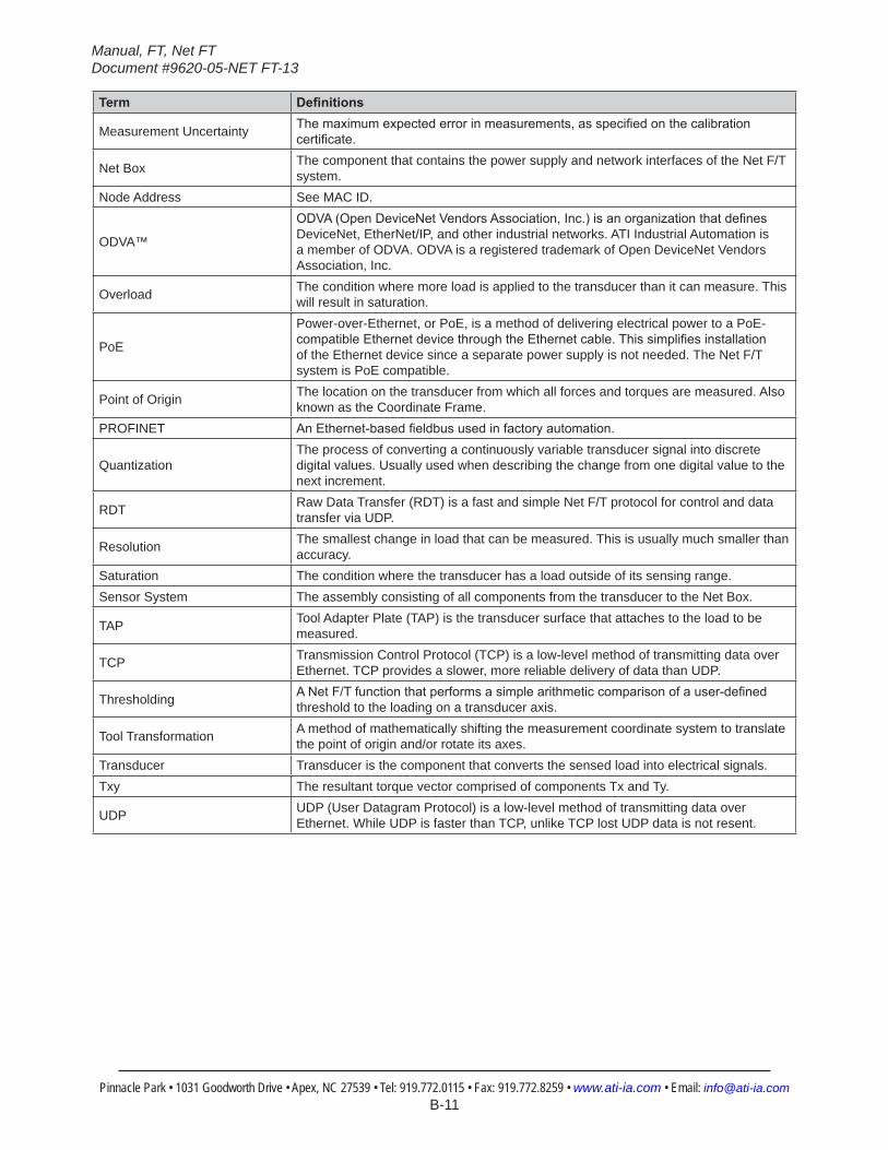
Term Definitions
Measurement Uncertainty Themaximumexpectederrorinmeasurements,asspecifiedonthecalibrationcertificate.
Net Box The component that contains the power supply and network interfaces of the Net F/T system.
Node Address See MAC ID.
ODVA™
ODVA(OpenDeviceNetVendorsAssociation,Inc.)isanorganizationthatdefinesDeviceNet, EtherNet/IP, and other industrial networks. ATI Industrial Automation is a member of ODVA. ODVA is a registered trademark of Open DeviceNet Vendors Association, Inc.
Overload The condition where more load is applied to the transducer than it can measure. This will result in saturation.
PoE
Power-over-Ethernet, or PoE, is a method of delivering electrical power to a PoE-compatibleEthernetdevicethroughtheEthernetcable.Thissimplifiesinstallationof the Ethernet device since a separate power supply is not needed. The Net F/T system is PoE compatible.
Point of Origin The location on the transducer from which all forces and torques are measured. Also known as the Coordinate Frame.
PROFINET AnEthernet-basedfieldbususedinfactoryautomation.
QuantizationThe process of converting a continuously variable transducer signal into discrete digital values. Usually used when describing the change from one digital value to the next increment.
RDT Raw Data Transfer (RDT) is a fast and simple Net F/T protocol for control and data transfer via UDP.
Resolution The smallest change in load that can be measured. This is usually much smaller than accuracy.
Saturation The condition where the transducer has a load outside of its sensing range.Sensor System The assembly consisting of all components from the transducer to the Net Box.
TAP Tool Adapter Plate (TAP) is the transducer surface that attaches to the load to be measured.
TCP Transmission Control Protocol (TCP) is a low-level method of transmitting data over Ethernet. TCP provides a slower, more reliable delivery of data than UDP.
Thresholding ANetF/Tfunctionthatperformsasimplearithmeticcomparisonofauser-definedthreshold to the loading on a transducer axis.
Tool Transformation A method of mathematically shifting the measurement coordinate system to translate the point of origin and/or rotate its axes.
Transducer Transducer is the component that converts the sensed load into electrical signals.Txy The resultant torque vector comprised of components Tx and Ty.
UDP UDP (User Datagram Protocol) is a low-level method of transmitting data over Ethernet. While UDP is faster than TCP, unlike TCP lost UDP data is not resent.
Manual, FT, Net FTDocument #9620-05-NET FT-13
Pinnacle Park • 1031 Goodworth Drive • Apex, NC 27539 • Tel: 919.772.0115 • Fax: 919.772.8259 • www.ati-ia.com • Email: [email protected] B-12
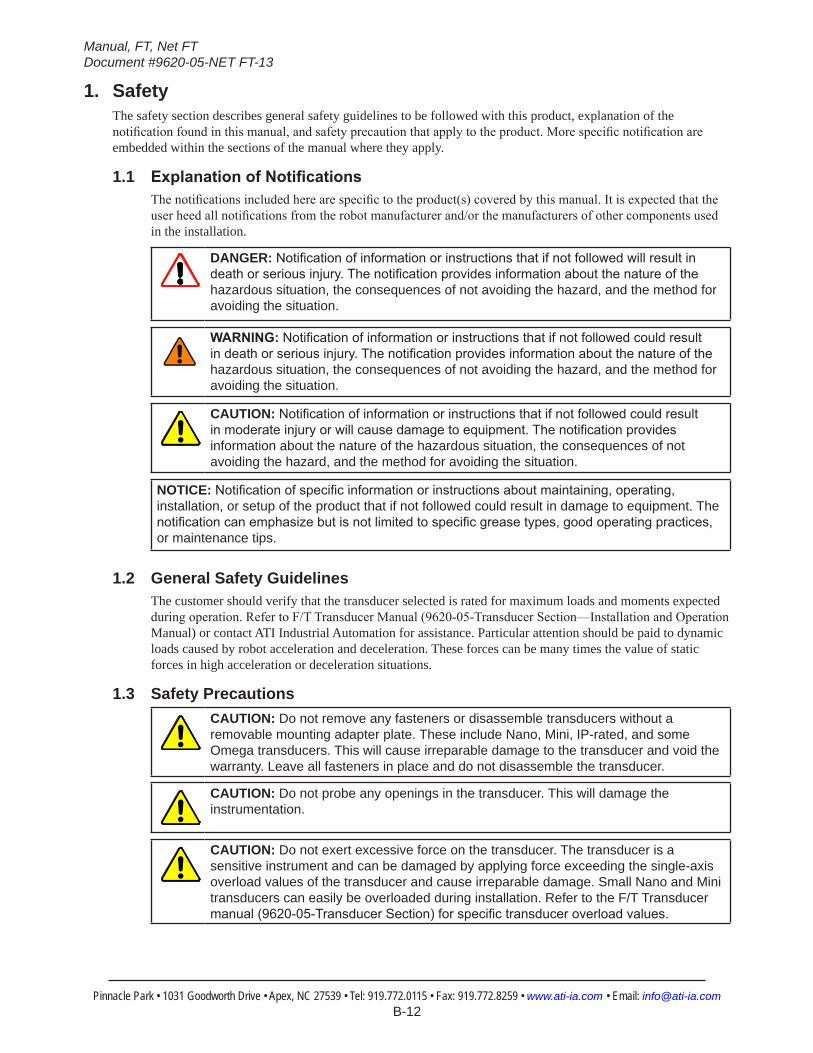
1. SafetyThe safety section describes general safety guidelines to be followed with this product, explanation of the notification found in this manual, and safety precaution that apply to the product. More specific notification are embedded within the sections of the manual where they apply.
1.1 ExplanationofNotificationsThe notifications included here are specific to the product(s) covered by this manual. It is expected that the user heed all notifications from the robot manufacturer and/or the manufacturers of other components used in the installation.
DANGER: Notificationofinformationorinstructionsthatifnotfollowedwillresultindeathorseriousinjury.Thenotificationprovidesinformationaboutthenatureofthehazardous situation, the consequences of not avoiding the hazard, and the method for avoiding the situation.
WARNING:Notificationofinformationorinstructionsthatifnotfollowedcouldresultindeathorseriousinjury.Thenotificationprovidesinformationaboutthenatureofthehazardous situation, the consequences of not avoiding the hazard, and the method for avoiding the situation.
CAUTION: Notificationofinformationorinstructionsthatifnotfollowedcouldresultinmoderateinjuryorwillcausedamagetoequipment.Thenotificationprovidesinformation about the nature of the hazardous situation, the consequences of not avoiding the hazard, and the method for avoiding the situation.
NOTICE: Notificationofspecificinformationorinstructionsaboutmaintaining,operating,installation, or setup of the product that if not followed could result in damage to equipment. The notificationcanemphasizebutisnotlimitedtospecificgreasetypes,goodoperatingpractices,or maintenance tips.
1.2 General Safety GuidelinesThe customer should verify that the transducer selected is rated for maximum loads and moments expected during operation. Refer to F/T Transducer Manual (9620-05-Transducer Section—Installation and Operation Manual) or contact ATI Industrial Automation for assistance. Particular attention should be paid to dynamic loads caused by robot acceleration and deceleration. These forces can be many times the value of static forces in high acceleration or deceleration situations.
1.3 Safety PrecautionsCAUTION: Do not remove any fasteners or disassemble transducers without a removable mounting adapter plate. These include Nano, Mini, IP-rated, and some Omega transducers. This will cause irreparable damage to the transducer and void the warranty. Leave all fasteners in place and do not disassemble the transducer.
CAUTION: Do not probe any openings in the transducer. This will damage the instrumentation.
CAUTION: Do not exert excessive force on the transducer. The transducer is a sensitive instrument and can be damaged by applying force exceeding the single-axis overload values of the transducer and cause irreparable damage. Small Nano and Mini transducers can easily be overloaded during installation. Refer to the F/T Transducer manual(9620-05-TransducerSection)forspecifictransduceroverloadvalues.
Manual, FT, Net FTDocument #9620-05-NET FT-13
Pinnacle Park • 1031 Goodworth Drive • Apex, NC 27539 • Tel: 919.772.0115 • Fax: 919.772.8259 • www.ati-ia.com • Email: [email protected] B-13
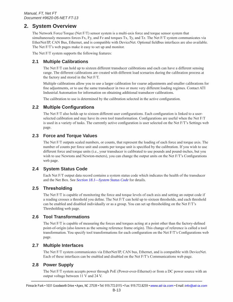
2. System OverviewThe Network Force/Torque (Net F/T) sensor system is a multi-axis force and torque sensor system that simultaneously measures forces Fx, Fy, and Fz and torques Tx, Ty, and Tz. The Net F/T system communicates via EtherNet/IP, CAN Bus, Ethernet, and is compatible with DeviceNet. Optional fieldbus interfaces are also available. The Net F/T’s web pages make it easy to set up and monitor.
The Net F/T system supports the following features:
2.1 Multiple CalibrationsThe Net F/T can hold up to sixteen different transducer calibrations and each can have a different sensing range. The different calibrations are created with different load scenarios during the calibration process at the factory and stored in the Net F/T. Multiple calibrations allow you to use a larger calibration for coarse adjustments and smaller calibrations for fine adjustments, or to use the same transducer in two or more very different loading regimes. Contact ATI Industrial Automation for information on obtaining additional transducer calibrations.The calibration to use is determined by the calibration selected in the active configuration.
2.2 MultipleConfigurationsThe Net F/T also holds up to sixteen different user configurations. Each configuration is linked to a user-selected calibration and may have its own tool transformation. Configurations are useful when the Net F/T is used in a variety of tasks. The currently active configuration is user selected on the Net F/T’s Settings web page.
2.3 Force and Torque ValuesThe Net F/T outputs scaled numbers, or counts, that represent the loading of each force and torque axis. The number of counts per force unit and counts per torque unit is specified by the calibration. If you wish to use different force and torque units (i.e., your transducer is calibrated to use pounds and pound-inches, but you wish to use Newtons and Newton-meters), you can change the output units on the Net F/T’s Configurations web page.
2.4 System Status CodeEach Net F/T output data record contains a system status code which indicates the health of the transducer and the Net Box. See Section 18.1—System Status Code for details.
2.5 ThresholdingThe Net F/T is capable of monitoring the force and torque levels of each axis and setting an output code if a reading crosses a threshold you define. The Net F/T can hold up to sixteen thresholds, and each threshold can be enabled and disabled individually or as a group. You can set up thresholding on the Net F/T’s Thresholding web page.
2.6 Tool TransformationsThe Net F/T is capable of measuring the forces and torques acting at a point other than the factory-defined point-of-origin (also known as the sensing reference frame origin). This change of reference is called a tool transformation. You specify tool transformations for each configuration on the Net F/T’s Configurations web page.
2.7 Multiple InterfacesThe Net F/T system communicates via EtherNet/IP, CAN bus, Ethernet, and is compatible with DeviceNet. Each of these interfaces can be enabled and disabled on the Net F/T’s Communications web page.
2.8 Power SupplyThe Net F/T system accepts power through PoE (Power-over-Ethernet) or from a DC power source with an output voltage between 11 V and 24 V.
Manual, FT, Net FTDocument #9620-05-NET FT-13
Pinnacle Park • 1031 Goodworth Drive • Apex, NC 27539 • Tel: 919.772.0115 • Fax: 919.772.8259 • www.ati-ia.com • Email: [email protected] B-14
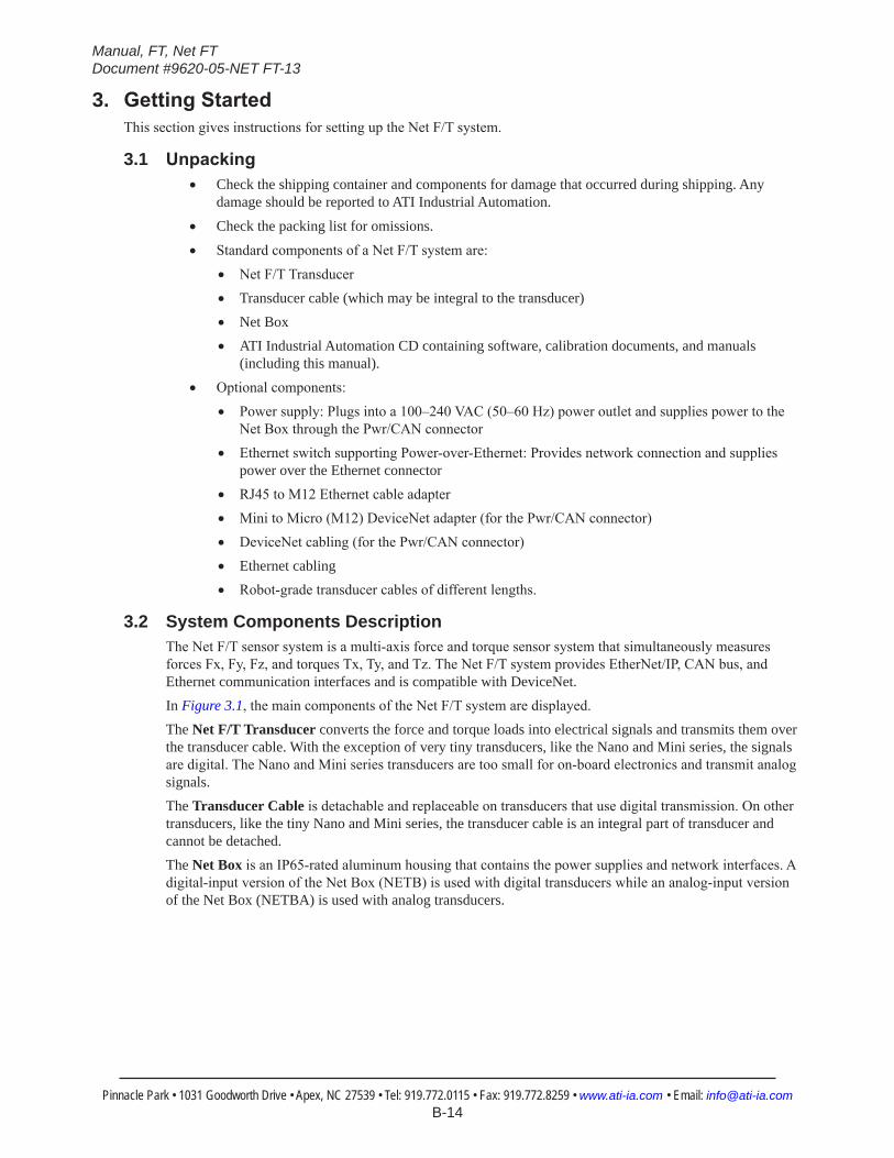
3. GettingStartedThis section gives instructions for setting up the Net F/T system.
3.1 Unpacking• Check the shipping container and components for damage that occurred during shipping. Any
damage should be reported to ATI Industrial Automation.
• Check the packing list for omissions.
• Standard components of a Net F/T system are:• Net F/T Transducer• Transducer cable (which may be integral to the transducer)• Net Box• ATI Industrial Automation CD containing software, calibration documents, and manuals
(including this manual).• Optional components:
• Power supply: Plugs into a 100–240 VAC (50–60 Hz) power outlet and supplies power to the Net Box through the Pwr/CAN connector
• Ethernet switch supporting Power-over-Ethernet: Provides network connection and supplies power over the Ethernet connector
• RJ45 to M12 Ethernet cable adapter• Mini to Micro (M12) DeviceNet adapter (for the Pwr/CAN connector)• DeviceNet cabling (for the Pwr/CAN connector)• Ethernet cabling• Robot-grade transducer cables of different lengths.
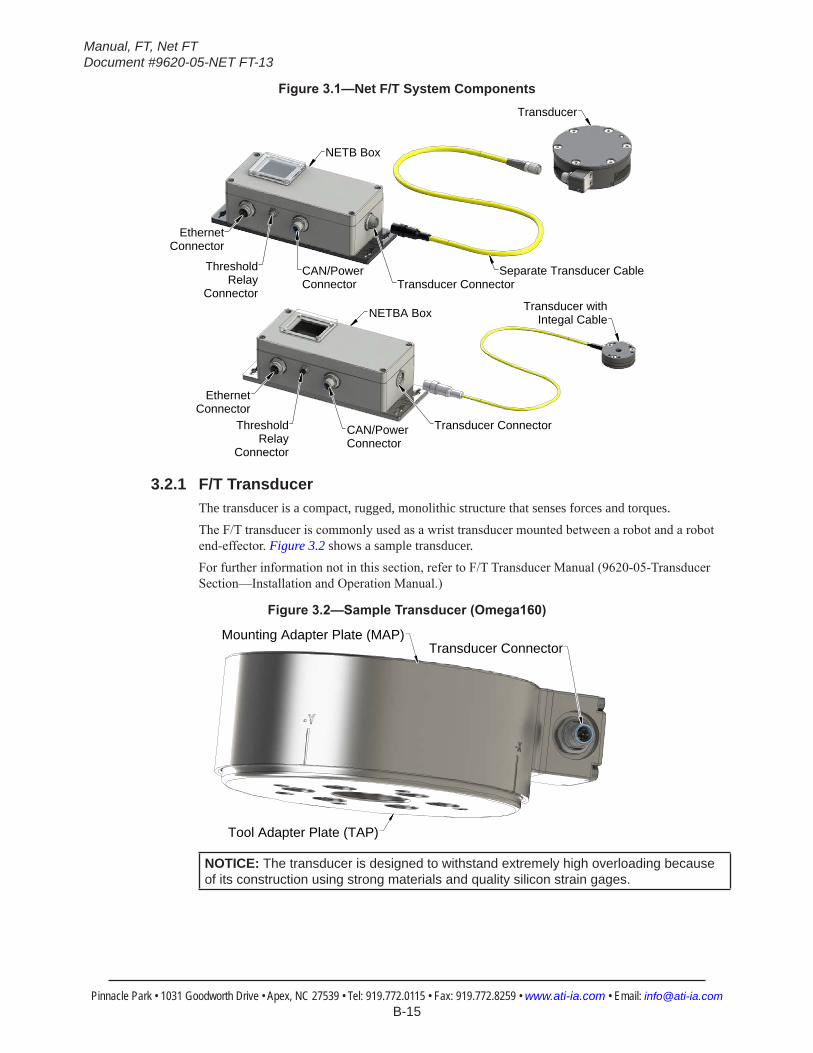
3.2 System Components DescriptionThe Net F/T sensor system is a multi-axis force and torque sensor system that simultaneously measures forces Fx, Fy, Fz, and torques Tx, Ty, and Tz. The Net F/T system provides EtherNet/IP, CAN bus, and Ethernet communication interfaces and is compatible with DeviceNet.In Figure 3.1, the main components of the Net F/T system are displayed.The Net F/T Transducer converts the force and torque loads into electrical signals and transmits them over the transducer cable. With the exception of very tiny transducers, like the Nano and Mini series, the signals are digital. The Nano and Mini series transducers are too small for on-board electronics and transmit analog signals.The Transducer Cable is detachable and replaceable on transducers that use digital transmission. On other transducers, like the tiny Nano and Mini series, the transducer cable is an integral part of transducer and cannot be detached.The Net Box is an IP65-rated aluminum housing that contains the power supplies and network interfaces. A digital-input version of the Net Box (NETB) is used with digital transducers while an analog-input version of the Net Box (NETBA) is used with analog transducers.
Manual, FT, Net FTDocument #9620-05-NET FT-13
Pinnacle Park • 1031 Goodworth Drive • Apex, NC 27539 • Tel: 919.772.0115 • Fax: 919.772.8259 • www.ati-ia.com • Email: [email protected] B-15
Figure3.1—Net F/T System Components
EthernetConnector
EthernetConnector
ThresholdRelay
Connector
ThresholdRelay
Connector
CAN/PowerConnector
CAN/PowerConnector
Separate Transducer Cable
NETBA Box
NETB Box
Transducer
Transducer withIntegal Cable
Transducer Connector
Transducer Connector
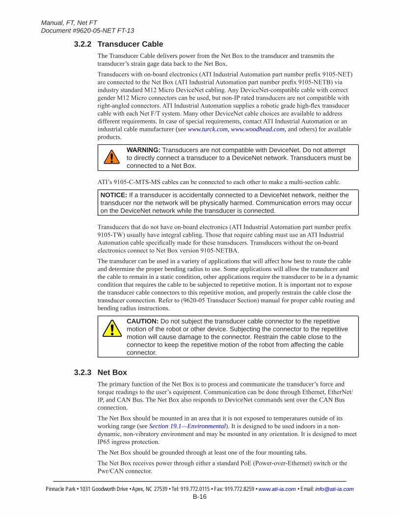
3.2.1 F/T TransducerThe transducer is a compact, rugged, monolithic structure that senses forces and torques. The F/T transducer is commonly used as a wrist transducer mounted between a robot and a robot end-effector. Figure 3.2 shows a sample transducer.For further information not in this section, refer to F/T Transducer Manual (9620-05-Transducer Section—Installation and Operation Manual.)
Figure3.2—SampleTransducer(Omega160)
Mounting Adapter Plate (MAP)
Tool Adapter Plate (TAP)
Transducer Connector
NOTICE: The transducer is designed to withstand extremely high overloading because of its construction using strong materials and quality silicon strain gages.
Manual, FT, Net FTDocument #9620-05-NET FT-13
Pinnacle Park • 1031 Goodworth Drive • Apex, NC 27539 • Tel: 919.772.0115 • Fax: 919.772.8259 • www.ati-ia.com • Email: [email protected] B-16
3.2.2 Transducer CableThe Transducer Cable delivers power from the Net Box to the transducer and transmits the transducer’s strain gage data back to the Net Box.Transducers with on-board electronics (ATI Industrial Automation part number prefix 9105-NET) are connected to the Net Box (ATI Industrial Automation part number prefix 9105-NETB) via industry standard M12 Micro DeviceNet cabling. Any DeviceNet-compatible cable with correct gender M12 Micro connectors can be used, but non-IP rated transducers are not compatible with right-angled connectors. ATI Industrial Automation supplies a robotic grade high-flex transducer cable with each Net F/T system. Many other DeviceNet cable choices are available to address different requirements. In case of special requirements, contact ATI Industrial Automation or an industrial cable manufacturer (see www.turck.com, www.woodhead.com, and others) for available products.
WARNING:Transducers are not compatible with DeviceNet. Do not attempt to directly connect a transducer to a DeviceNet network. Transducers must be connected to a Net Box.
ATI’s 9105-C-MTS-MS cables can be connected to each other to make a multi-section cable.
NOTICE: If a transducer is accidentally connected to a DeviceNet network, neither the transducer nor the network will be physically harmed. Communication errors may occur on the DeviceNet network while the transducer is connected.
Transducers that do not have on-board electronics (ATI Industrial Automation part number prefix 9105-TW) usually have integral cabling. Those that require cabling must use an ATI Industrial Automation cable specifically made for these transducers. Transducers without the on-board electronics connect to Net Box version 9105-NETBA.The transducer can be used in a variety of applications that will affect how best to route the cable and determine the proper bending radius to use. Some applications will allow the transducer and the cable to remain in a static condition, other applications require the transducer to be in a dynamic condition that requires the cable to be subjected to repetitive motion. It is important not to expose the transducer cable connectors to this repetitive motion, and properly restrain the cable close the transducer connection. Refer to (9620-05 Transducer Section) manual for proper cable routing and bending radius instructions.
CAUTION: Do not subject the transducer cable connector to the repetitive motion of the robot or other device. Subjecting the connector to the repetitive motion will cause damage to the connector. Restrain the cable close to the connector to keep the repetitive motion of the robot from affecting the cable connector.
3.2.3 Net BoxThe primary function of the Net Box is to process and communicate the transducer’s force and torque readings to the user’s equipment. Communication can be done through Ethernet, EtherNet/IP, and CAN Bus. The Net Box also responds to DeviceNet commands sent over the CAN Bus connection.The Net Box should be mounted in an area that it is not exposed to temperatures outside of its working range (see Section 19.1—Environmental). It is designed to be used indoors in a non-dynamic, non-vibratory environment and may be mounted in any orientation. It is designed to meet IP65 ingress protection.The Net Box should be grounded through at least one of the four mounting tabs.The Net Box receives power through either a standard PoE (Power-over-Ethernet) switch or the Pwr/CAN connector.
Manual, FT, Net FTDocument #9620-05-NET FT-13
Pinnacle Park • 1031 Goodworth Drive • Apex, NC 27539 • Tel: 919.772.0115 • Fax: 919.772.8259 • www.ati-ia.com • Email: [email protected] B-17
3.3 ConnectingtheSystemComponents
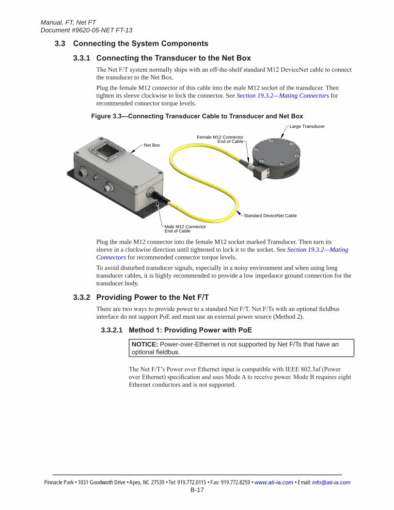
3.3.1 ConnectingtheTransducertotheNetBoxThe Net F/T system normally ships with an off-the-shelf standard M12 DeviceNet cable to connect the transducer to the Net Box.Plug the female M12 connector of this cable into the male M12 socket of the transducer. Then tighten its sleeve clockwise to lock the connector. See Section 19.3.2—Mating Connectors for recommended connector torque levels.
Figure3.3—ConnectingTransducerCabletoTransducerandNetBox
Female M12 ConnectorEnd of Cable
Male M12 ConnectorEnd of Cable
Large Transducer
Net Box
Standard DeviceNet Cable
Plug the male M12 connector into the female M12 socket marked Transducer. Then turn its sleeve in a clockwise direction until tightened to lock it to the socket. See Section 19.3.2—Mating Connectors for recommended connector torque levels.To avoid disturbed transducer signals, especially in a noisy environment and when using long transducer cables, it is highly recommended to provide a low impedance ground connection for the transducer body.
3.3.2 ProvidingPowertotheNetF/TThere are two ways to provide power to a standard Net F/T. Net F/Ts with an optional fieldbus interface do not support PoE and must use an external power source (Method 2).
3.3.2.1 Method1:ProvidingPowerwithPoE
NOTICE: Power-over-Ethernet is not supported by Net F/Ts that have an optionalfieldbus.
The Net F/T’s Power over Ethernet input is compatible with IEEE 802.3af (Power over Ethernet) specification and uses Mode A to receive power. Mode B requires eight Ethernet conductors and is not supported.
Manual, FT, Net FTDocument #9620-05-NET FT-13
Pinnacle Park • 1031 Goodworth Drive • Apex, NC 27539 • Tel: 919.772.0115 • Fax: 919.772.8259 • www.ati-ia.com • Email: [email protected] B-18
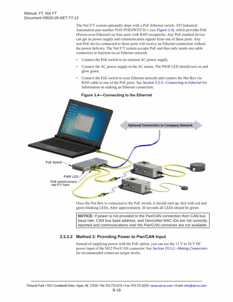
The Net F/T system optionally ships with a PoE Ethernet switch. ATI Industrial Automation part number 9105-POESWITCH-1 (see Figure 3.4), which provides PoE (Power-over-Ethernet) on four ports with RJ45 receptacles. Any PoE enabled device can get its power supply and communication signals from one of these ports. Any non-PoE device connected to these ports will receive an Ethernet connection without the power delivery. The Net F/T system accepts PoE and thus only needs one cable connection to function on an Ethernet network.
• Connect the PoE switch to its external AC power supply.
• Connect the AC power supply to the AC mains. The PWR LED should turn on and glow green.
• Connect the PoE switch to your Ethernet network and connect the Net Box via RJ45 cable to one of the PoE ports. See Section 3.3.3—Connecting to Ethernet for information on making an Ethernet connection.
Figure3.4—ConnectingtotheEthernet
PoE Switch
PWR LEDPoE portsConnect Net F/T here
Optional Connection to Company Network
Once the Net Box is connected to the PoE switch, it should start up, first with red and green blinking LEDs. After approximately 20 seconds all LEDs should be green.
NOTICE: If power is not provided to the Pwr/CAN connection then CAN bus baud rate, CAN bus base address, and DeviceNet MAC IDs are not correctly reported and communications over the Pwr/CAN connector are not available.
3.3.2.2 Method2:ProvidingPowertoPwr/CANInputInstead of supplying power with the PoE option, you can use the 11 V to 24 V DC power input of the M12 Pwr/CAN connector. See Section 19.3.2—Mating Connectors for recommended connector torque levels.
Manual, FT, Net FTDocument #9620-05-NET FT-13
Pinnacle Park • 1031 Goodworth Drive • Apex, NC 27539 • Tel: 919.772.0115 • Fax: 919.772.8259 • www.ati-ia.com • Email: [email protected] B-19
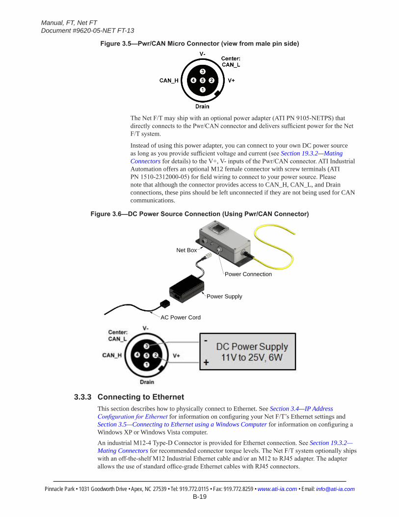
Figure3.5—Pwr/CANMicroConnector(viewfrommalepinside)
The Net F/T may ship with an optional power adapter (ATI PN 9105-NETPS) that directly connects to the Pwr/CAN connector and delivers sufficient power for the Net F/T system.
Instead of using this power adapter, you can connect to your own DC power source as long as you provide sufficient voltage and current (see Section 19.3.2—Mating Connectors for details) to the V+, V- inputs of the Pwr/CAN connector. ATI Industrial Automation offers an optional M12 female connector with screw terminals (ATI PN 1510-2312000-05) for field wiring to connect to your power source. Please note that although the connector provides access to CAN_H, CAN_L, and Drain connections, these pins should be left unconnected if they are not being used for CAN communications.
Figure3.6—DCPowerSourceConnection(UsingPwr/CANConnector)
AC Power Cord
Power Supply
Net Box
Power Connection
3.3.3 ConnectingtoEthernetThis section describes how to physically connect to Ethernet. See Section 3.4—IP Address Configuration for Ethernet for information on configuring your Net F/T’s Ethernet settings and Section 3.5—Connecting to Ethernet using a Windows Computer for information on configuring a Windows XP or Windows Vista computer.An industrial M12-4 Type-D Connector is provided for Ethernet connection. See Section 19.3.2—Mating Connectors for recommended connector torque levels. The Net F/T system optionally ships with an off-the-shelf M12 Industrial Ethernet cable and/or an M12 to RJ45 adapter. The adapter allows the use of standard office-grade Ethernet cables with RJ45 connectors.

Manual, FT, Net FTDocument #9620-05-NET FT-13
Pinnacle Park • 1031 Goodworth Drive • Apex, NC 27539 • Tel: 919.772.0115 • Fax: 919.772.8259 • www.ati-ia.com • Email: [email protected] B-20
Figure3.7—EthernetM12-4,Type-DConnector(viewfromfemalepinside)
There are two ways that the Net Box can connect to Ethernet.
NOTICE: To achieve the best Ethernet performance (and to reduce the likelihood of loosing data), we recommend connecting the Net Box directly to the host computer, as described in Option 2.
3.3.3.1 Option 1: Connect to an Ethernet NetworkUse the M12 to RJ45 adapter to connect a standard RJ45 Ethernet cable to the Net Box. Be certain to tighten the sleeve fully clockwise to lock the connector.
Plug the other end of the Ethernet cable into the port of an Ethernet switch. See Figure 3.8 for a proposed setup.
Figure3.8—ConnectingtoEthernet
RJ45 Connection
M12 Connection
Net Box
AdapterCable
Standard RJ45 Cable
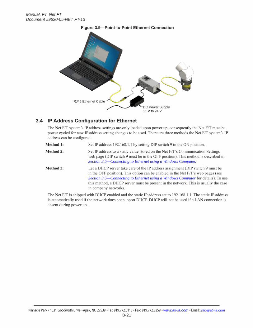
3.3.3.2 Option 2: Connect directly to a Computer’s Ethernet InterfaceThe Net F/T system is connected directly to a computer’s Ethernet port via a cable and is not connected to an Ethernet switch. Use the M12 to RJ45 adapter to connect a standard RJ45 Ethernet cable to the Net box. The most basic configuration would be a point-to-point connection between a computer’s Ethernet interface and the Net F/T’s Ethernet interface (see Figure 3.9). In this case, power has to be provided via the Pwr/CAN connector (see Section 3.3.2.2—Method 2: Providing Power to Pwr/CAN Input for details). This configuration has the lowest latency and lowest chance of lost data packages and provides the best high-speed connection.
If necessary, the computer may be connected to an Ethernet network via a second Ethernet port on the computer. Note that most computers do not have a second Ethernet port and one may need to be installed. Doing so is outside the scope of this document. Contact your IT department for assistance.
Manual, FT, Net FTDocument #9620-05-NET FT-13
Pinnacle Park • 1031 Goodworth Drive • Apex, NC 27539 • Tel: 919.772.0115 • Fax: 919.772.8259 • www.ati-ia.com • Email: [email protected] B-21
Figure3.9—Point-to-Point Ethernet Connection
RJ45 Ethernet Cable
DC Power Supply11 V to 24 V
3.4 IPAddressConfigurationforEthernetThe Net F/T system’s IP address settings are only loaded upon power up, consequently the Net F/T must be power cycled for new IP address setting changes to be used. There are three methods the Net F/T system’s IP address can be configured.
Method 1: Set IP address 192.168.1.1 by setting DIP switch 9 to the ON position.
Method 2: Set IP address to a static value stored on the Net F/T’s Communication Settings web page (DIP switch 9 must be in the OFF position). This method is described in Section 3.5—Connecting to Ethernet using a Windows Computer.
Method 3: Let a DHCP server take care of the IP address assignment (DIP switch 9 must be in the OFF position). This option can be enabled in the Net F/T’s web pages (see Section 3.5—Connecting to Ethernet using a Windows Computer for details). To use this method, a DHCP server must be present in the network. This is usually the case in company networks.
The Net F/T is shipped with DHCP enabled and the static IP address set to 192.168.1.1. The static IP address is automatically used if the network does not support DHCP. DHCP will not be used if a LAN connection is absent during power up.
Manual, FT, Net FTDocument #9620-05-NET FT-13
Pinnacle Park • 1031 Goodworth Drive • Apex, NC 27539 • Tel: 919.772.0115 • Fax: 919.772.8259 • www.ati-ia.com • Email: [email protected] B-22
3.5 ConnectingtoEthernetusingaWindowsComputerMost of the Ethernet configuration is performed via the Net F/T’s web pages. To initially access the web pages, you will need to configure your Net F/T to work on your network by getting it assigned an IP address and telling it some basic information about your network.For purposes of this initial connection, your computer will be connected directly to the Net F/T and disconnected from your LAN. You will be temporarily giving your computer a fixed IP address of 192.168.1.100. It is important that the Ethernet cable to the Net F/T is disconnected from your computer during this step.
NOTICE: If your computer has multiple connections to Ethernet, such as a LAN connection and a wireless connection, be sure to select the LAN that will be connected to the Net F/T.
1. Unplug the Ethernet cable from the LAN port on your computer.2. Open your computer’s Internet Protocol (TCP IP) Properties window. Follow the instructions below for
your computer’s operating system.
3.5.1 WindowsVistaandWindows7a. From the Start menu, select Control Panel.
b. For Vista, click on Control Panel Home.
c. Click on the Network and Internet icon.
d. Click on the Network and Sharing Center icon.
e. For Vista, click on the Manage Network Connections task link. For Windows 7, click on the Local Area Connection link.
f. For Vista, right-click on Local Area Connection and select the Properties button. For Windows 7, click on the Properties button.
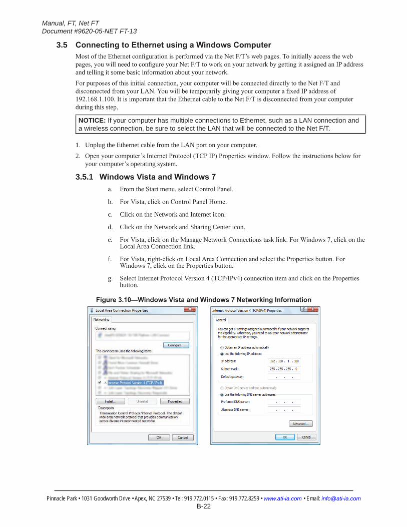
g. Select Internet Protocol Version 4 (TCP/IPv4) connection item and click on the Properties button.
Figure3.10—WindowsVistaandWindows7NetworkingInformation
Manual, FT, Net FTDocument #9620-05-NET FT-13
Pinnacle Park • 1031 Goodworth Drive • Apex, NC 27539 • Tel: 919.772.0115 • Fax: 919.772.8259 • www.ati-ia.com • Email: [email protected] B-23
3.5.2 WindowsXPa. From the Start menu, select Control Panel.
b. Open the Network Connections icon from within the Control Panel. If your Control Panel says Pick a category at the top, you will need to first click on the Network and Internet Connections icon.
c. Click on the Network Connections icon.
d. Right-click on Local Area Connection and select Properties.
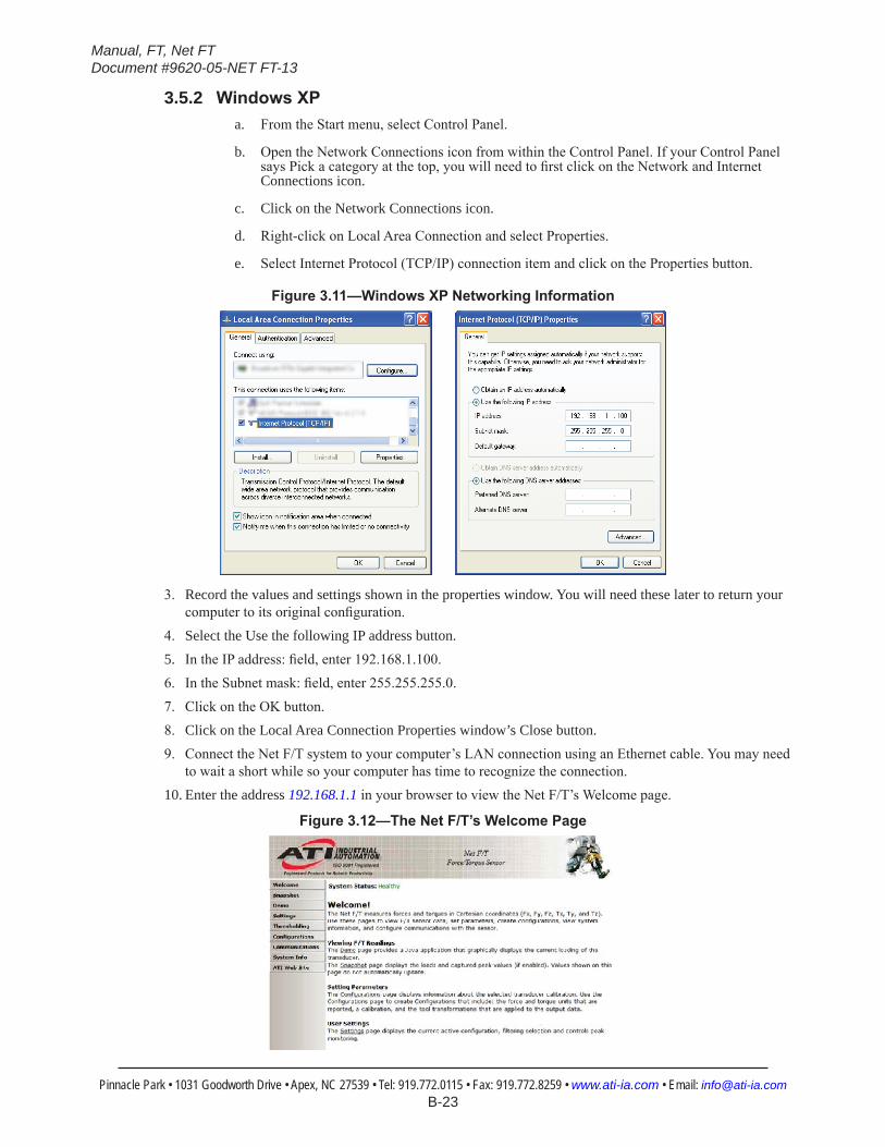
e. Select Internet Protocol (TCP/IP) connection item and click on the Properties button.
Figure3.11—WindowsXPNetworkingInformation
3. Record the values and settings shown in the properties window. You will need these later to return your computer to its original configuration.
4. Select the Use the following IP address button.5. In the IP address: field, enter 192.168.1.100.6. In the Subnet mask: field, enter 255.255.255.0.7. Click on the OK button.8. Click on the Local Area Connection Properties window’s Close button.9. Connect the Net F/T system to your computer’s LAN connection using an Ethernet cable. You may need
to wait a short while so your computer has time to recognize the connection.10. Enter the address 192.168.1.1 in your browser to view the Net F/T’s Welcome page.
Figure3.12—TheNetF/T’sWelcomePage
Manual, FT, Net FTDocument #9620-05-NET FT-13
Pinnacle Park • 1031 Goodworth Drive • Apex, NC 27539 • Tel: 919.772.0115 • Fax: 919.772.8259 • www.ati-ia.com • Email: [email protected] B-24
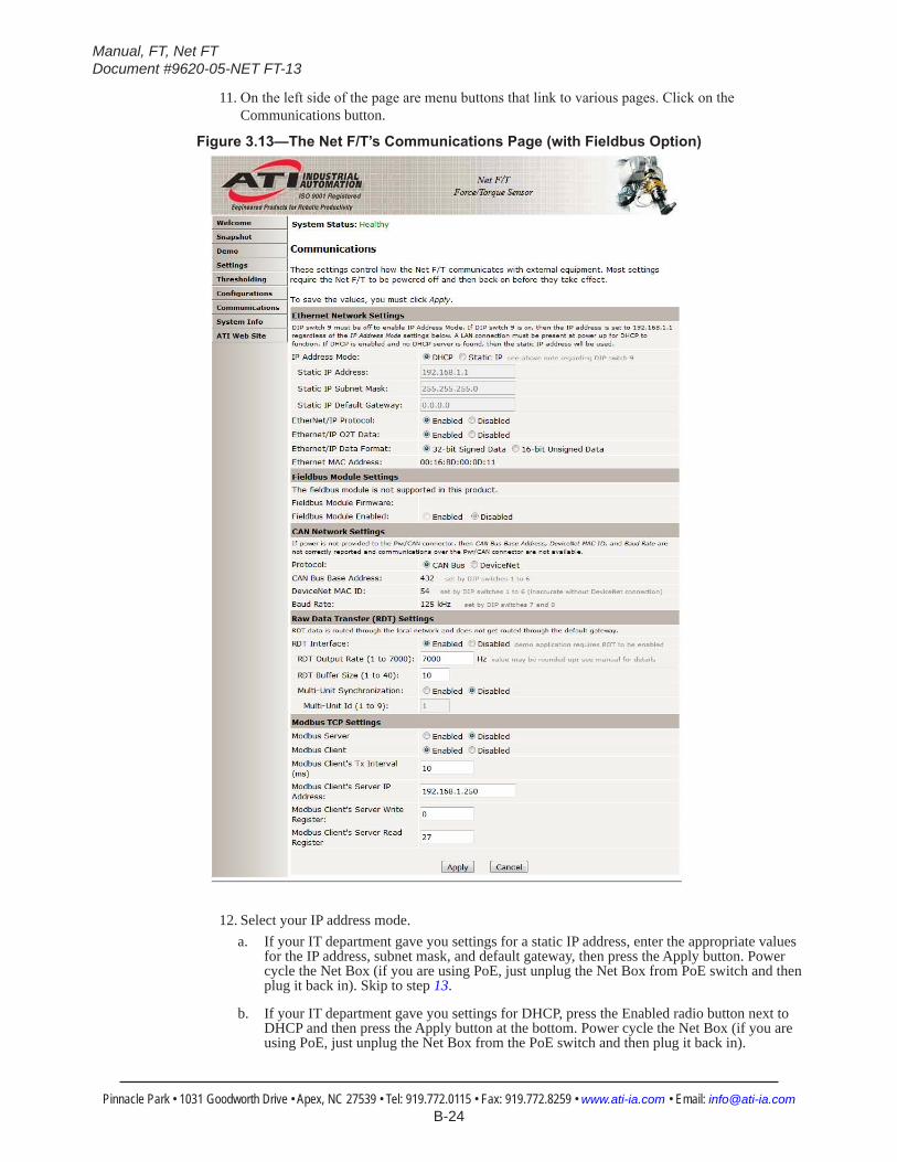
11. On the left side of the page are menu buttons that link to various pages. Click on the Communications button.
Figure3.13—TheNetF/T’sCommunicationsPage(withFieldbusOption)
12. Select your IP address mode.a. If your IT department gave you settings for a static IP address, enter the appropriate values
for the IP address, subnet mask, and default gateway, then press the Apply button. Power cycle the Net Box (if you are using PoE, just unplug the Net Box from PoE switch and then plug it back in). Skip to step 13.
b. If your IT department gave you settings for DHCP, press the Enabled radio button next to DHCP and then press the Apply button at the bottom. Power cycle the Net Box (if you are using PoE, just unplug the Net Box from the PoE switch and then plug it back in).
Manual, FT, Net FTDocument #9620-05-NET FT-13
Pinnacle Park • 1031 Goodworth Drive • Apex, NC 27539 • Tel: 919.772.0115 • Fax: 919.772.8259 • www.ati-ia.com • Email: [email protected] B-25
Next, determine the IP address assigned to the Net F/T by following the instructions in Section 6.1—Finding Net F/Ts on the Network.
NOTICE: IP addresses assigned by a DHCP server are not permanent and may change if the Net F/T is disconnected from the network for a period of time. Contact your IT department for more information.
13. Open up the TCP/IP properties of your local area connection again. Restore the settings to where they were before you reconfigured them (use the values you recorded in Step 3).
14. Open up a new web browser window, enter the IP address you gave (or the DHCP server has assigned to the Net F/T) the Net F/T system into the browser’s address bar, and press Enter. The Net F/T’s Welcome page should display again. You can now communicate with the Net F/T over your network without needing to configure the communications settings again.
NOTICE: IftheNetFTConfigurationUtilityfoundtheNetF/T,buttheinternetbrowserisunable to open the found IP address, you may need to clear previous device entries from the computer’s ARP table by restarting the computer or, if you have administrative privileges, by going to the computer’s Start menu, selecting Run..., and entering “arp –d *”.
This should only be necessary if another device previously occupied the same IP address that the Net F/T is now using.
3.6 ConnectingtoanEthernet-basedFieldbusNet F/Ts with an optional fieldbus module connect to the fieldbus via the Net F/T’s standard Ethernet connection. Although the fieldbus uses the same Ethernet connection as the Net F/T uses for its standard communications, the fieldbus option has its own MAC address and its own IP address. The fieldbus’s MAC address is shown as MAC ID 2 on the connector side of the Net Box.To be used, the fieldbus module option must be enabled on the Net F/T’s Communications page.
3.7 ConnectingtoDeviceNet(usingDeviceNet-CompatibilityMode)The Net F/T system has a DeviceNet compatibility mode which allows operation over a DeviceNet network. The DeviceNet-compatibility mode fully implements all DeviceNet commands. The DeviceNet MAC ID address and baud rate settings follow Section 3.9—DIP Switches and Termination Resistor. For protocol information, refer to Section 13—DeviceNet-Compatibility Mode Operation.The Net F/T Pwr/CAN connector matches standard DeviceNet connectors and connections. The Pwr/CAN connector mates to a standard female DeviceNet M12 connector.
3.8 ConnectingtheNetBoxtoaCANBusNetworkThe Net F/T supports a basic CAN protocol. The CAN Bus base address and baud rate settings follow Section 3.9—DIP Switches and Termination Resistor. For protocol information refer to Section 15—CAN Bus Operation.
3.9 DIP Switches and Termination ResistorThe configuration DIP switches and termination resistor are located inside of the Net Box where they are safely protected from outside debris and liquids. The cover of the Net Box must be removed to gain access to these.Before opening the Net Box, make sure that the box is not powered and that you and the Net Box are electrically grounded.To remove the cover, fully loosen each of the four screws that fasten the cover to the Net Box chassis. The cover can then be removed by lifting it straight up and off of the chassis.
Manual, FT, Net FTDocument #9620-05-NET FT-13
Pinnacle Park • 1031 Goodworth Drive • Apex, NC 27539 • Tel: 919.772.0115 • Fax: 919.772.8259 • www.ati-ia.com • Email: [email protected] B-26
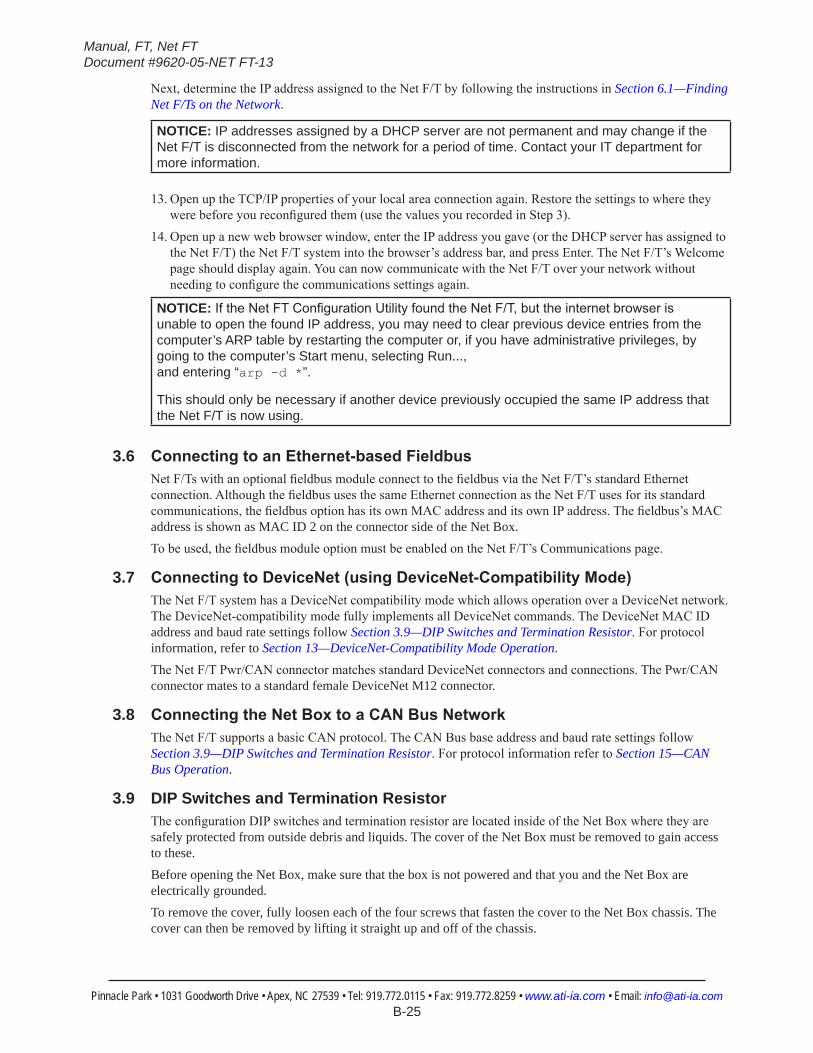
The internal electronics have a clear shield to help protect them from debris or errant tool movements. There are access holes in the shield for the DIP switches and termination resistor jumper.
Figure3.14—NetBoxDIPSwitches,TerminationResistorandLEDs
Loosen Screws Loosen Screws
DIP Switches
CAN bus Termination Jumper
Status LEDs
Before replacing the Net Box cover, you must ensure that no debris or liquids are in the chassis. To replace the Net Box cover, place the cover back on the chassis (verify that the window is above the LEDs and DIP switches) and tighten the four screws until each is snug.
3.9.1 Termination ResistorBy default, the Net Box ships with a CAN bus termination resistor installed. Remove the termination jumper if you want to disable the internal termination resistor. To remove the termination resistor, you will need to use a pair of tweezers or pliers to pull the jumper off. Safely store the jumper somewhere in case you need to re-enable the termination resistor.
3.9.2 Node AddressBy default, the Net Box ships with a CAN Bus base address of 432 and DeviceNet MAC ID of 54. These are defined by the DIP switch settings (see Figure 3.15 for details).
Manual, FT, Net FTDocument #9620-05-NET FT-13
Pinnacle Park • 1031 Goodworth Drive • Apex, NC 27539 • Tel: 919.772.0115 • Fax: 919.772.8259 • www.ati-ia.com • Email: [email protected] B-27
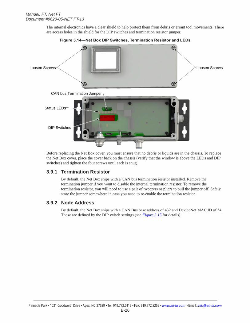
Figure3.15—NetBoxDIPSwitches,TerminationResistorandLEDs
Use Table 3.1 and Table 3.2 as an aid for finding the switch settings to set the desired address. The numbers on the left side of the colons are the desired MAC ID while the numbers on the right side represent the switch settings for switches 1 through 6 to select the MAC ID. The number 1 represents a switch in the ON position and the number 0 represents a switch in the OFF position.
NOTICE: The Net F/T can operate in either the CAN Bus protocol or the DeviceNet-Compatibility Mode protocol, but not both protocols. The desired protocol can be enabled on the Net F/T’s Communications web page.
Both protocols use the same DIP switches to set their address. Be sure to use the correct address table for your protocol.
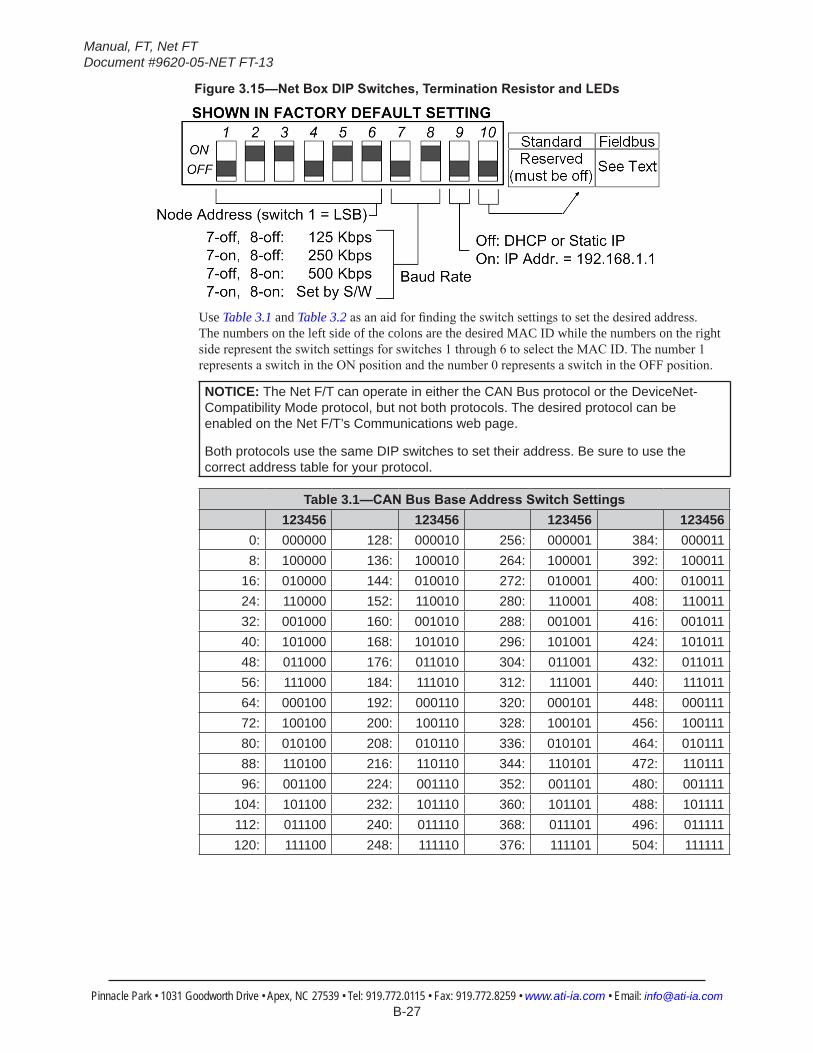
Table 3.1—CANBusBaseAddressSwitchSettings123456 123456 123456 123456
0: 000000 128: 000010 256: 000001 384: 0000118: 100000 136: 100010 264: 100001 392: 100011
16: 010000 144: 010010 272: 010001 400: 01001124: 110000 152: 110010 280: 110001 408: 11001132: 001000 160: 001010 288: 001001 416: 00101140: 101000 168: 101010 296: 101001 424: 10101148: 011000 176: 011010 304: 011001 432: 01101156: 111000 184: 111010 312: 111001 440: 11101164: 000100 192: 000110 320: 000101 448: 00011172: 100100 200: 100110 328: 100101 456: 10011180: 010100 208: 010110 336: 010101 464: 01011188: 110100 216: 110110 344: 110101 472: 11011196: 001100 224: 001110 352: 001101 480: 001111
104: 101100 232: 101110 360: 101101 488: 101111112: 011100 240: 011110 368: 011101 496: 011111120: 111100 248: 111110 376: 111101 504: 111111
Manual, FT, Net FTDocument #9620-05-NET FT-13
Pinnacle Park • 1031 Goodworth Drive • Apex, NC 27539 • Tel: 919.772.0115 • Fax: 919.772.8259 • www.ati-ia.com • Email: [email protected] B-28
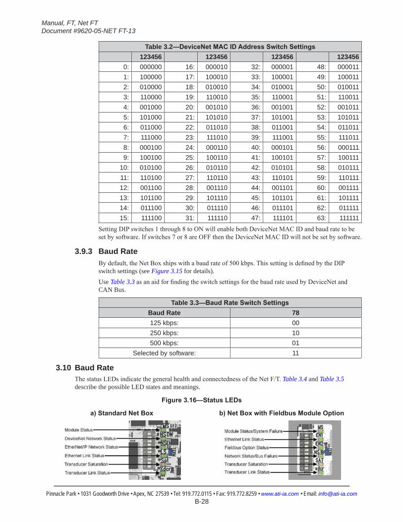
Table 3.2—DeviceNetMACIDAddressSwitchSettings123456 123456 123456 123456
0: 000000 16: 000010 32: 000001 48: 0000111: 100000 17: 100010 33: 100001 49: 1000112: 010000 18: 010010 34: 010001 50: 0100113: 110000 19: 110010 35: 110001 51: 1100114: 001000 20: 001010 36: 001001 52: 0010115: 101000 21: 101010 37: 101001 53: 1010116: 011000 22: 011010 38: 011001 54: 0110117: 111000 23: 111010 39: 111001 55: 1110118: 000100 24: 000110 40: 000101 56: 0001119: 100100 25: 100110 41: 100101 57: 100111
10: 010100 26: 010110 42: 010101 58: 01011111: 110100 27: 110110 43: 110101 59: 11011112: 001100 28: 001110 44: 001101 60: 00111113: 101100 29: 101110 45: 101101 61: 10111114: 011100 30: 011110 46: 011101 62: 01111115: 111100 31: 111110 47: 111101 63: 111111
Setting DIP switches 1 through 8 to ON will enable both DeviceNet MAC ID and baud rate to be set by software. If switches 7 or 8 are OFF then the DeviceNet MAC ID will not be set by software.
3.9.3 Baud RateBy default, the Net Box ships with a baud rate of 500 kbps. This setting is defined by the DIP switch settings (see Figure 3.15 for details).Use Table 3.3 as an aid for finding the switch settings for the baud rate used by DeviceNet and CAN Bus.
Table 3.3—BaudRateSwitchSettingsBaud Rate 78125 kbps: 00250 kbps: 10500 kbps: 01
Selected by software: 11
3.10 Baud RateThe status LEDs indicate the general health and connectedness of the Net F/T. Table 3.4 and Table 3.5 describe the possible LED states and meanings.
Figure3.16—StatusLEDs
a)StandardNetBox b)NetBoxwithFieldbusModuleOption
Manual, FT, Net FTDocument #9620-05-NET FT-13
Pinnacle Park • 1031 Goodworth Drive • Apex, NC 27539 • Tel: 919.772.0115 • Fax: 919.772.8259 • www.ati-ia.com • Email: [email protected] B-29
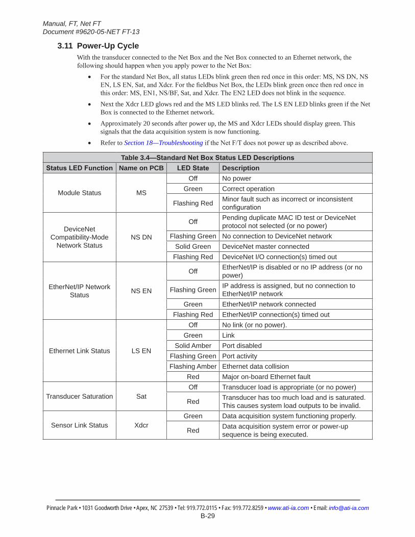
3.11 Power-Up CycleWith the transducer connected to the Net Box and the Net Box connected to an Ethernet network, the following should happen when you apply power to the Net Box:
• For the standard Net Box, all status LEDs blink green then red once in this order: MS, NS DN, NS EN, LS EN, Sat, and Xdcr. For the fieldbus Net Box, the LEDs blink green once then red once in this order: MS, EN1, NS/BF, Sat, and Xdcr. The EN2 LED does not blink in the sequence.
• Next the Xdcr LED glows red and the MS LED blinks red. The LS EN LED blinks green if the Net Box is connected to the Ethernet network.
• Approximately 20 seconds after power up, the MS and Xdcr LEDs should display green. This signals that the data acquisition system is now functioning.
• Refer to Section 18—Troubleshooting if the Net F/T does not power up as described above.
Table 3.4—StandardNetBoxStatusLEDDescriptionsStatusLEDFunction Name on PCB LEDState Description
Module Status MS
Off No powerGreen Correct operation
Flashing Red Minor fault such as incorrect or inconsistent configuration
DeviceNet Compatibility-Mode
Network StatusNS DN
Off Pending duplicate MAC ID test or DeviceNet protocol not selected (or no power)
Flashing Green No connection to DeviceNet networkSolid Green DeviceNet master connected
Flashing Red DeviceNet I/O connection(s) timed out
EtherNet/IP Network Status NS EN
Off EtherNet/IP is disabled or no IP address (or no power)
Flashing Green IP address is assigned, but no connection to EtherNet/IP network
Green EtherNet/IP network connectedFlashing Red EtherNet/IP connection(s) timed out
Ethernet Link Status LS EN
Off No link (or no power).Green Link
Solid Amber Port disabledFlashing Green Port activityFlashing Amber Ethernet data collision
Red Major on-board Ethernet fault
Transducer Saturation SatOff Transducer load is appropriate (or no power)
Red Transducer has too much load and is saturated. This causes system load outputs to be invalid.
Sensor Link Status XdcrGreen Data acquisition system functioning properly.
Red Data acquisition system error or power-up sequence is being executed.
Manual, FT, Net FTDocument #9620-05-NET FT-13
Pinnacle Park • 1031 Goodworth Drive • Apex, NC 27539 • Tel: 919.772.0115 • Fax: 919.772.8259 • www.ati-ia.com • Email: [email protected] B-30
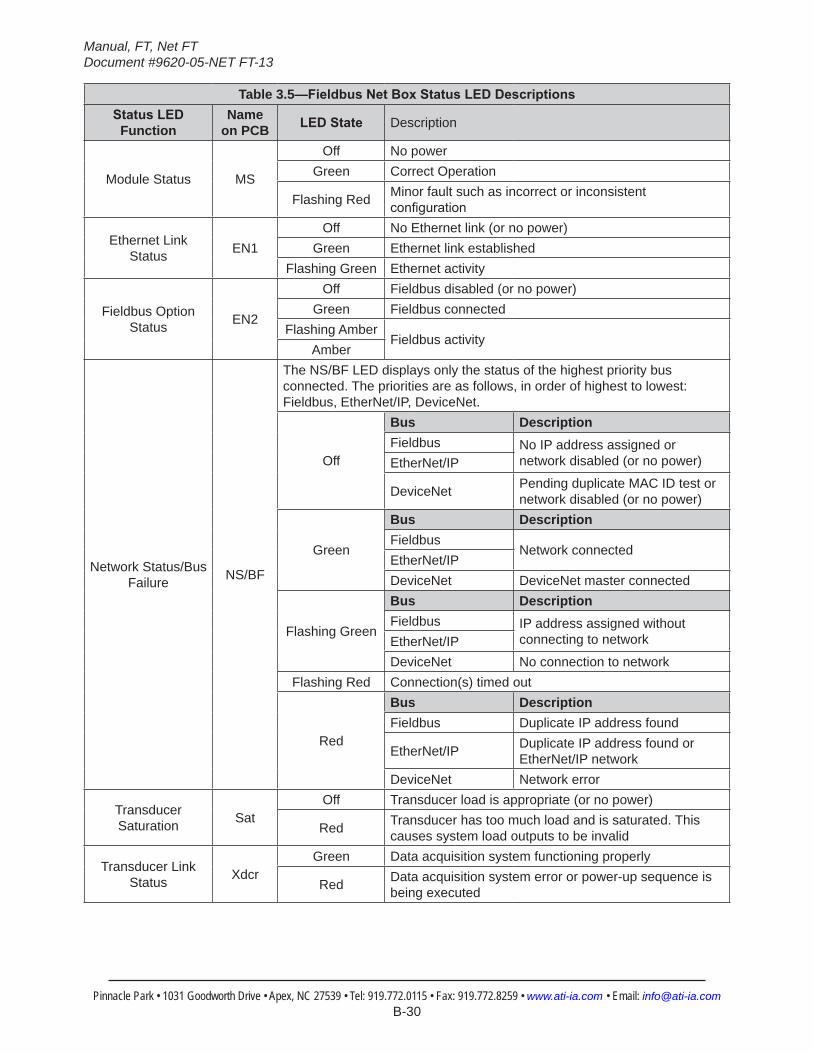
Table 3.5—FieldbusNetBoxStatusLEDDescriptionsStatusLED
FunctionName
on PCB LEDState Description
Module Status MS
Off No powerGreen Correct Operation
Flashing Red Minor fault such as incorrect or inconsistent configuration
Ethernet Link Status EN1
Off No Ethernet link (or no power)Green Ethernet link established
Flashing Green Ethernet activity
Fieldbus Option Status EN2
Off Fieldbus disabled (or no power)Green Fieldbus connected
Flashing AmberFieldbus activity
Amber
Network Status/Bus Failure NS/BF
The NS/BF LED displays only the status of the highest priority bus connected. The priorities are as follows, in order of highest to lowest: Fieldbus, EtherNet/IP, DeviceNet.
Off
Bus DescriptionFieldbus No IP address assigned or
network disabled (or no power)EtherNet/IP
DeviceNet Pending duplicate MAC ID test or network disabled (or no power)
Green
Bus DescriptionFieldbus
Network connectedEtherNet/IPDeviceNet DeviceNet master connected
Flashing Green
Bus DescriptionFieldbus IP address assigned without
connecting to networkEtherNet/IPDeviceNet No connection to network
Flashing Red Connection(s) timed out
Red
Bus DescriptionFieldbus Duplicate IP address found
EtherNet/IP Duplicate IP address found or EtherNet/IP network
DeviceNet Network error
Transducer Saturation Sat
Off Transducer load is appropriate (or no power)
Red Transducer has too much load and is saturated. This causes system load outputs to be invalid
Transducer Link Status Xdcr
Green Data acquisition system functioning properly
Red Data acquisition system error or power-up sequence is being executed
Manual, FT, Net FTDocument #9620-05-NET FT-13
Pinnacle Park • 1031 Goodworth Drive • Apex, NC 27539 • Tel: 919.772.0115 • Fax: 919.772.8259 • www.ati-ia.com • Email: [email protected] B-31
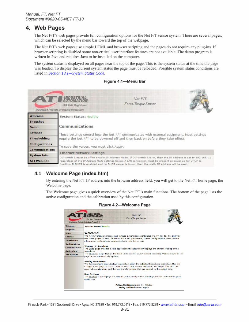
4. WebPagesThe Net F/T’s web pages provide full configuration options for the Net F/T sensor system. There are several pages, which can be selected by the menu bar toward the top of the webpage.
The Net F/T’s web pages use simple HTML and browser scripting and the pages do not require any plug-ins. If browser scripting is disabled some non-critical user interface features are not available. The demo program is written in Java and requires Java to be installed on the computer.
The system status is displayed on all pages near the top of the page. This is the system status at the time the page was loaded. To display the current system status the page must be reloaded. Possible system status conditions are listed in Section 18.1—System Status Code.
Figure4.1—Menu Bar
4.1 WelcomePage(index.htm)By entering the Net F/T IP address into the browser address field, you will get to the Net F/T home page, the Welcome page.The Welcome page gives a quick overview of the Net F/T’s main functions. The bottom of the page lists the active configuration and the calibration used by this configuration.
Figure4.2—WelcomePage
Manual, FT, Net FTDocument #9620-05-NET FT-13
Pinnacle Park • 1031 Goodworth Drive • Apex, NC 27539 • Tel: 919.772.0115 • Fax: 919.772.8259 • www.ati-ia.com • Email: [email protected] B-32
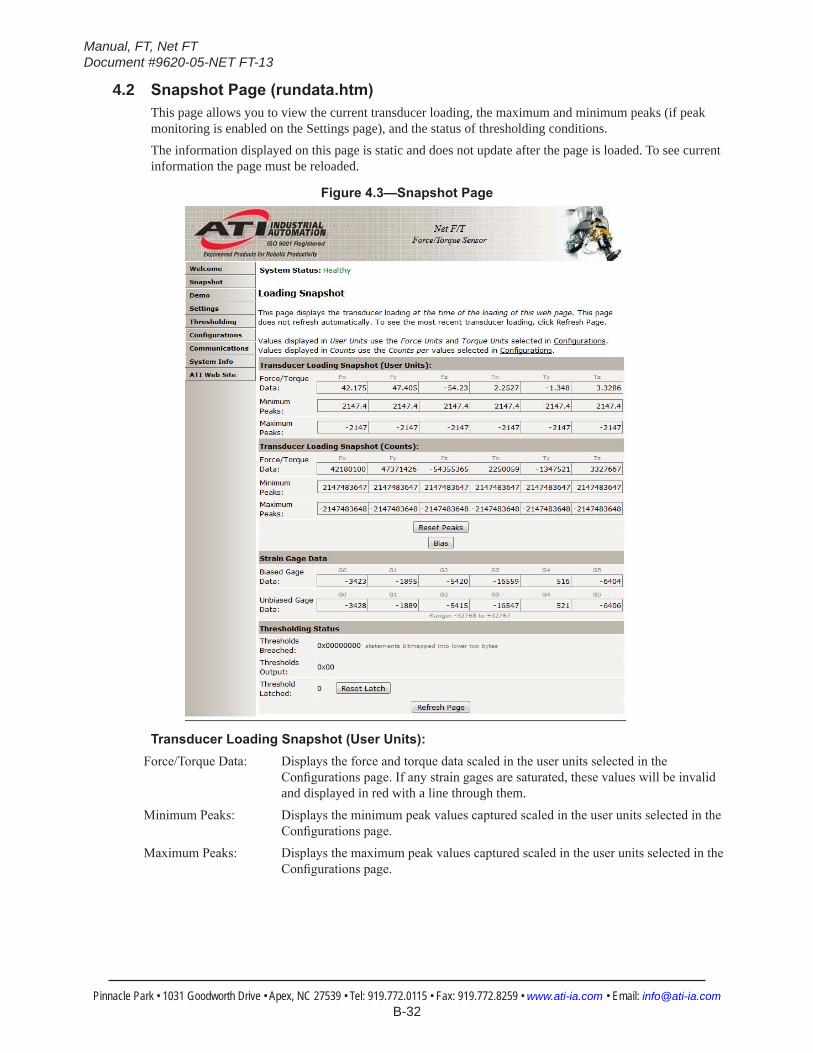
4.2 SnapshotPage(rundata.htm)This page allows you to view the current transducer loading, the maximum and minimum peaks (if peak monitoring is enabled on the Settings page), and the status of thresholding conditions.The information displayed on this page is static and does not update after the page is loaded. To see current information the page must be reloaded.
Figure4.3—SnapshotPage
TransducerLoadingSnapshot(UserUnits):Force/Torque Data: Displays the force and torque data scaled in the user units selected in the
Configurations page. If any strain gages are saturated, these values will be invalid and displayed in red with a line through them.
Minimum Peaks: Displays the minimum peak values captured scaled in the user units selected in the Configurations page.
Maximum Peaks: Displays the maximum peak values captured scaled in the user units selected in the Configurations page.

Manual, FT, Net FTDocument #9620-05-NET FT-13
Pinnacle Park • 1031 Goodworth Drive • Apex, NC 27539 • Tel: 919.772.0115 • Fax: 919.772.8259 • www.ati-ia.com • Email: [email protected] B-33
Transducer Loading Snapshot (Counts):Force/Torque Data: Displays the force and torque data scaled with the Counts per Force and Counts per
Torque displayed in the Configurations page. If any strain gages are saturated, these values will be invalid and displayed in red with a line through them.
Minimum Peaks: Displays the minimum peak values captured scaled with the Counts per Force and Counts per Torque displayed in the Configurations page.
Maximum Peaks: Displays the maximum peak values captured scaled with the Counts per Force and Counts per Torque displayed in the Configurations page.
Reset Peaks button: Clears the captured peaks and reloads the Snapshot page.
Bias button: Tares the force and torque values at the current readings and reloads the Snapshot page. This sets the current load level as the new zero point. This can be undone by setting the Software Bias Vector to all zeros on the Settings page.
Strain Gage Data:Biased Gage Data: Displays the transducer’s strain gages minus the software bias vector.
Unbiased Gage Data: Displays the transducer’s raw strain gage information for easy troubleshooting of saturation errors. Saturated strain gage values are displayed in red.
NOTICE: When saturation occurs, the reported force and torque values are invalid.
NOTICE: Individual strain-gage values do not correspond to individual force and torque axes.
NOTICE: The transducer readings on this page are captured as the web page requests them. It is possible that the readings towards the bottom of the page come from later F/T data records than the readings towards the top of the page.
Thresholding Status:Thresholds Breached: Indicates which threshold conditions are or have been true since the last reset latch
function execution. Each bit in the lower two bytes of this hexadecimal number represents a thresholding statement. Table 4.1 shows the bit pattern representing each thresholding statement number. The Thresholds Breached value is the result of or’ing the bit patterns for all true statements together. The Thresholds Breached value is cleared to zero by the reset latch function.
Table 4.1—Bit Patterns for Thresholds Breached#: Bit Pattern #: Bit Pattern #: Bit Pattern #: Bit Pattern0: 0x00000001 4: 0x00000010 8: 0x00000100 12: 0x000010001: 0x00000002 5: 0x00000020 9: 0x00000200 13: 0x000020002: 0x00000004 6: 0x00000040 10: 0x00000400 14: 0x000040003: 0x00000008 7: 0x00000080 11: 0x00000800 15: 0x00008000
Thresholds Output: Displays the Thresholds Output value set by bitwise or’ing the Output Codes of all true thresholding statements.
Threshold Latched: Displays a one if any threshold conditions are or have been true. The Threshold Latched value is cleared to zero by the reset latch function.
Reset Latch button: Clears any threshold latching and reloads the Snapshot page. If no threshold conditions remain true then Thresholds Breached, Thresholds Output, and Threshold Latched will all be set to zero and the System Status: Threshold Level Latched condition will be cleared.
Refresh Page button: Reloads the Snapshot page with updated values. This is the same as using the browser’s reload or refresh command.
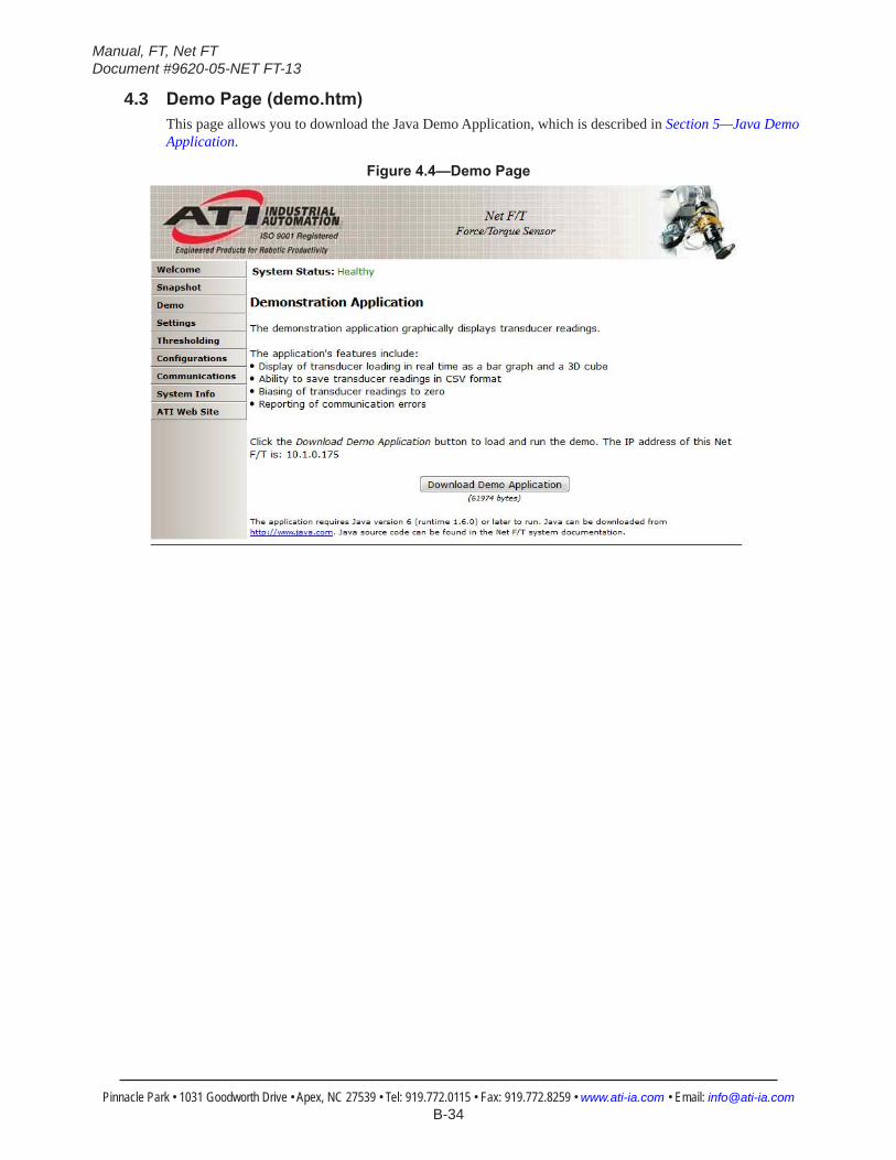
Manual, FT, Net FTDocument #9620-05-NET FT-13
Pinnacle Park • 1031 Goodworth Drive • Apex, NC 27539 • Tel: 919.772.0115 • Fax: 919.772.8259 • www.ati-ia.com • Email: [email protected] B-34
4.3 DemoPage(demo.htm)This page allows you to download the Java Demo Application, which is described in Section 5—Java Demo Application.
Figure4.4—DemoPage
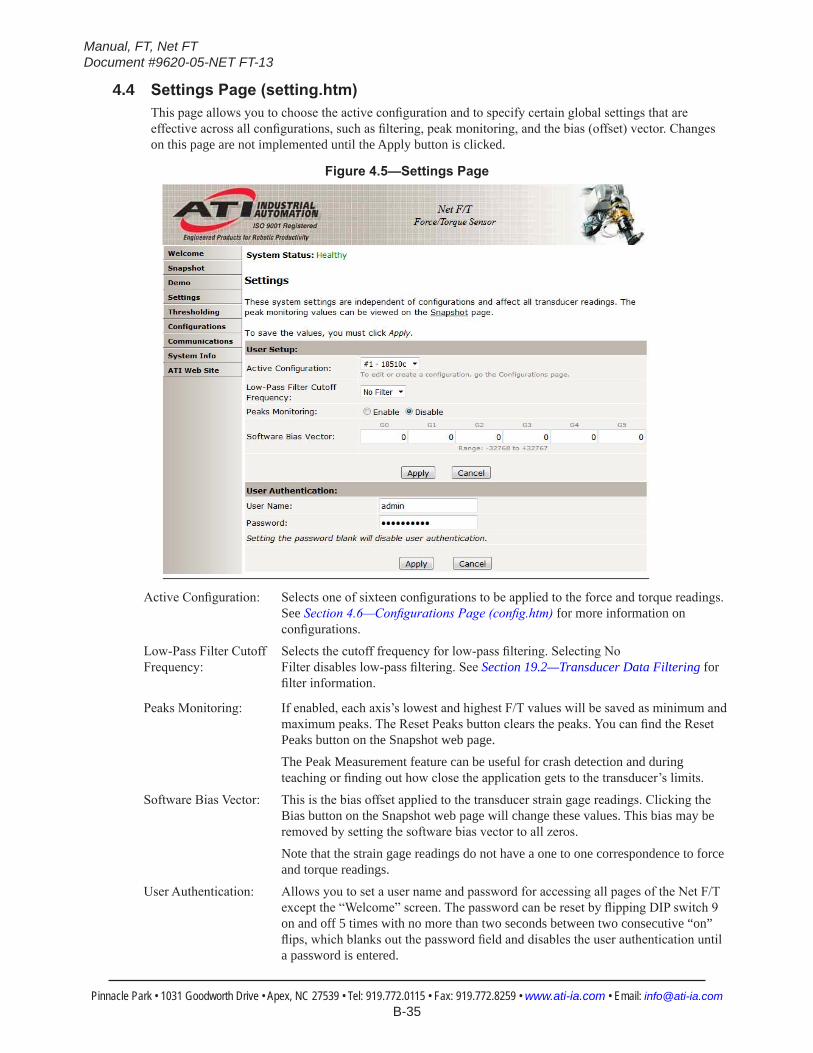
Manual, FT, Net FTDocument #9620-05-NET FT-13
Pinnacle Park • 1031 Goodworth Drive • Apex, NC 27539 • Tel: 919.772.0115 • Fax: 919.772.8259 • www.ati-ia.com • Email: [email protected] B-35
4.4 SettingsPage(setting.htm)This page allows you to choose the active configuration and to specify certain global settings that are effective across all configurations, such as filtering, peak monitoring, and the bias (offset) vector. Changes on this page are not implemented until the Apply button is clicked.
Figure4.5—SettingsPage
Active Configuration: Selects one of sixteen configurations to be applied to the force and torque readings. See Section 4.6—Configurations Page (config.htm) for more information on configurations.
Low-Pass Filter Cutoff Selects the cutoff frequency for low-pass filtering. Selecting NoFrequency: Filter disables low-pass filtering. See Section 19.2—Transducer Data Filtering for
filter information.
Peaks Monitoring: If enabled, each axis’s lowest and highest F/T values will be saved as minimum and maximum peaks. The Reset Peaks button clears the peaks. You can find the Reset Peaks button on the Snapshot web page.
The Peak Measurement feature can be useful for crash detection and during teaching or finding out how close the application gets to the transducer’s limits.
Software Bias Vector: This is the bias offset applied to the transducer strain gage readings. Clicking the Bias button on the Snapshot web page will change these values. This bias may be removed by setting the software bias vector to all zeros.
Note that the strain gage readings do not have a one to one correspondence to force and torque readings.
User Authentication: Allows you to set a user name and password for accessing all pages of the Net F/T except the “Welcome” screen. The password can be reset by flipping DIP switch 9 on and off 5 times with no more than two seconds between two consecutive “on” flips, which blanks out the password field and disables the user authentication until a password is entered.
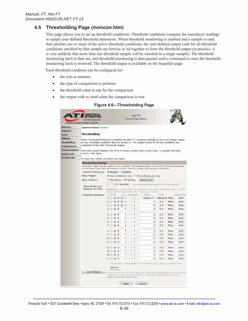
Manual, FT, Net FTDocument #9620-05-NET FT-13
Pinnacle Park • 1031 Goodworth Drive • Apex, NC 27539 • Tel: 919.772.0115 • Fax: 919.772.8259 • www.ati-ia.com • Email: [email protected] B-36
4.5 ThresholdingPage(moncon.htm)This page allows you to set up threshold conditions. Threshold conditions compare the transducer readings to simple user-defined threshold statements. When threshold monitoring is enabled and a sample is read that satisfies one or more of the active threshold conditions, the user-defined output code for all threshold conditions satisfied by that sample are bitwise or’ed together to form the threshold output (in practice, it is very unlikely that more than one threshold sample will be satisfied in a single sample). The threshold monitoring latch is then set, and threshold monitoring is then paused until a command to reset the threshold monitoring latch is received. The threshold output is available on the Snapshot page.Each threshold condition can be configured for:
• the axis to monitor
• the type of comparison to perform
• the threshold value to use for the comparison
• the output code to send when the comparison is true
Figure4.6—ThresholdingPage
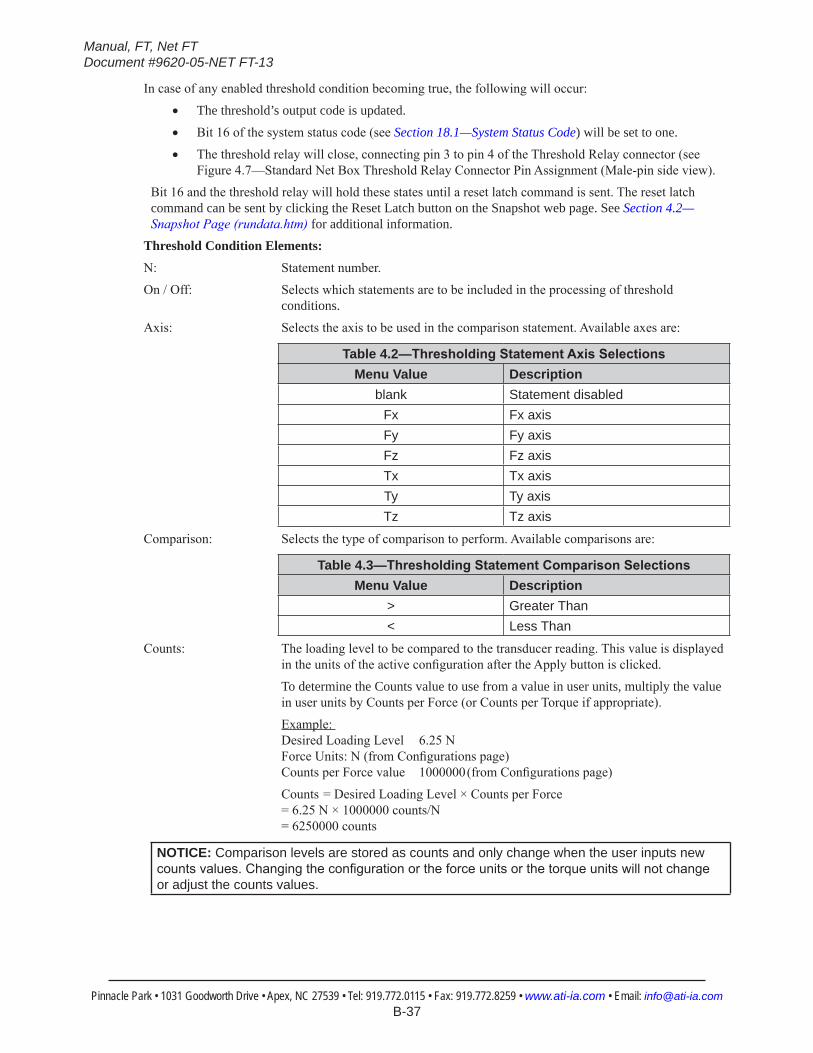
Manual, FT, Net FTDocument #9620-05-NET FT-13
Pinnacle Park • 1031 Goodworth Drive • Apex, NC 27539 • Tel: 919.772.0115 • Fax: 919.772.8259 • www.ati-ia.com • Email: [email protected] B-37
In case of any enabled threshold condition becoming true, the following will occur:
• The threshold’s output code is updated.
• Bit 16 of the system status code (see Section 18.1—System Status Code) will be set to one.
• The threshold relay will close, connecting pin 3 to pin 4 of the Threshold Relay connector (see Figure 4.7—Standard Net Box Threshold Relay Connector Pin Assignment (Male-pin side view).
Bit 16 and the threshold relay will hold these states until a reset latch command is sent. The reset latch command can be sent by clicking the Reset Latch button on the Snapshot web page. See Section 4.2—Snapshot Page (rundata.htm) for additional information.
Threshold Condition Elements:N: Statement number.
On / Off: Selects which statements are to be included in the processing of threshold conditions.
Axis: Selects the axis to be used in the comparison statement. Available axes are:
Table 4.2—ThresholdingStatementAxisSelectionsMenu Value Description
blank Statement disabledFx Fx axisFy Fy axisFz Fz axisTx Tx axisTy Ty axisTz Tz axis
Comparison: Selects the type of comparison to perform. Available comparisons are:
Table 4.3—ThresholdingStatementComparisonSelectionsMenu Value Description
> Greater Than< Less Than
Counts: The loading level to be compared to the transducer reading. This value is displayed in the units of the active configuration after the Apply button is clicked.
To determine the Counts value to use from a value in user units, multiply the value in user units by Counts per Force (or Counts per Torque if appropriate).
Example: Desired Loading Level 6.25 N Force Units: N (from Configurations page) Counts per Force value 1000000 (from Configurations page)
Counts = Desired Loading Level × Counts per Force = 6.25 N × 1000000 counts/N = 6250000 counts
NOTICE: Comparison levels are stored as counts and only change when the user inputs new countsvalues.Changingtheconfigurationortheforceunitsorthetorqueunitswillnotchangeor adjust the counts values.
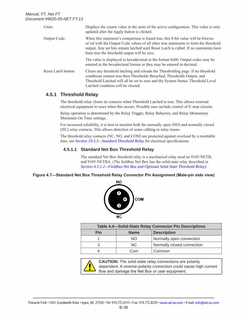
Manual, FT, Net FTDocument #9620-05-NET FT-13
Pinnacle Park • 1031 Goodworth Drive • Apex, NC 27539 • Tel: 919.772.0115 • Fax: 919.772.8259 • www.ati-ia.com • Email: [email protected] B-38
Units: Displays the counts value in the units of the active configuration. This value is only updated after the Apply button is clicked.
Output Code: When this statement’s comparison is found true, this 8-bit value will be bitwise or’ed with the Output Code values of all other true statements to form the threshold output. Any set bits remain latched until Reset Latch is called. If no statements have been true the threshold output will be zero.
The value is displayed in hexadecimal in the format 0x00. Output codes may be entered in the hexadecimal format or they may be entered in decimal.
Reset Latch button: Clears any threshold latching and reloads the Thresholding page. If no threshold conditions remain true then Thresholds Breached, Thresholds Output, and Threshold Latched will all be set to zero and the System Status: Threshold Level Latched condition will be cleared.
4.5.1 Threshold RelayThe threshold relay closes its contacts when Threshold Latched is true. This allows external electrical equipment to react when this occurs. Possible uses include control of E-stop circuits.Relay operation is determined by the Relay Trigger, Relay Behavior, and Relay Momentary Minimum-On Time settings.For increased reliability, it is best to monitor both the normally open (NO) and normally closed (NC) relay contacts. This allows detection of some cabling or relay issues.The threshold relay contacts (NC, NO, and COM) are protected against overload by a resettable fuse, see Section 19.3.3—Standard Threshold Relay for electrical specifications.
4.5.1.1 Standard Net Box Threshold RelayThe standard Net Box threshold relay is a mechanical relay used on 9105-NETB, and 9105-NETBA. (The fieldbus Net Box has the solid-state relay described in Section 4.5.1.2—Fieldbus Net Box and Optional Solid State Threshold Relay).
Figure4.7—StandardNetBoxThresholdRelayConnectorPinAssignment(Male-pinsideview)
Table 4.4—Solid-State Relay Connector Pin DescriptionsPin Name Description1 NO Normally open connection3 NC Normally closed connection4 Com Common
CAUTION: The solid-state relay connections are polarity dependent. A reverse-polarity connection could cause high current flowanddamagetheNetBoxoruserequipment.

Manual, FT, Net FTDocument #9620-05-NET FT-13
Pinnacle Park • 1031 Goodworth Drive • Apex, NC 27539 • Tel: 919.772.0115 • Fax: 919.772.8259 • www.ati-ia.com • Email: [email protected] B-39
Figure4.8—ExampleCircuitforStandardNetBoxThresholdRelayMonitoring
ComNO
NC
4
1
3
+Voltage
Activ e-High Output
Threshold RelayNet Box
Activ e-Low Output
R R
Figure4.9—Example Circuit for a Relay Interface
ComNO
NC 1
4
3
+Voltage
Threshold RelayNet Box
Activ e-High Output
R
+Voltage
User Relay orMonitoringEquipment
The standard threshold relay contacts (NC, NO, and Com) are protected against overload by a self-resetting fuse. The maximum guaranteed fuse hold current is 50 mA.
The relay will completely close its contacts within 6 ms.
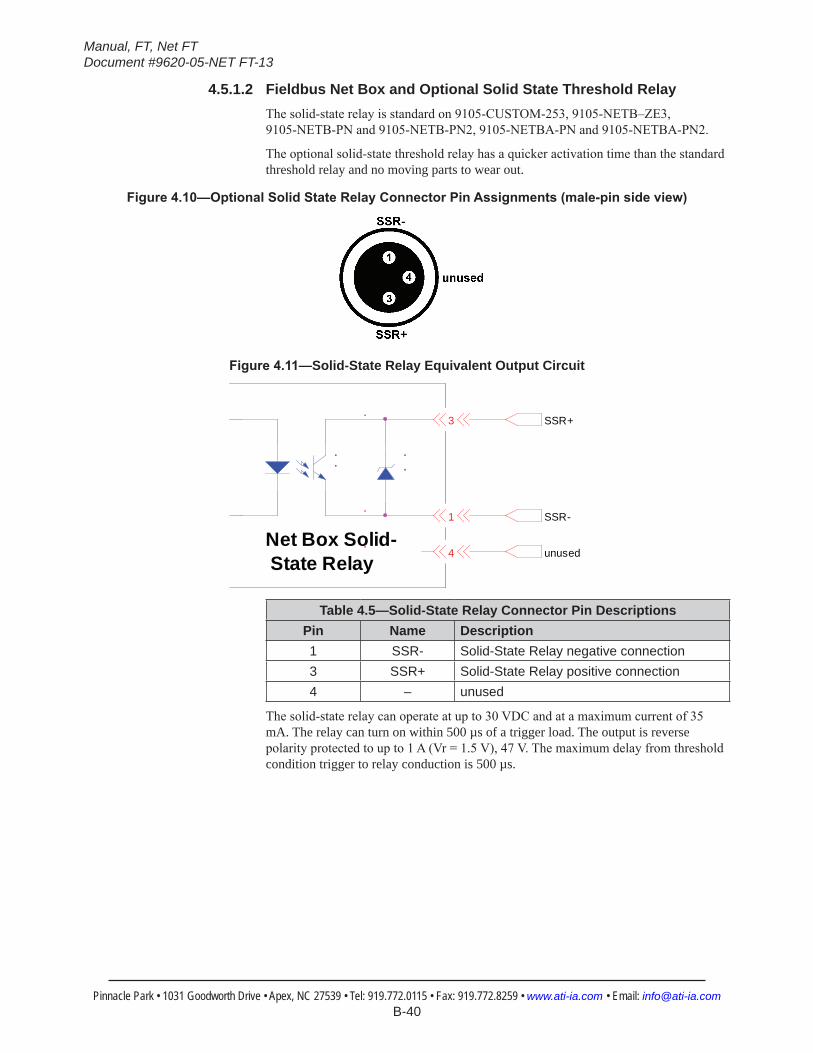
Manual, FT, Net FTDocument #9620-05-NET FT-13
Pinnacle Park • 1031 Goodworth Drive • Apex, NC 27539 • Tel: 919.772.0115 • Fax: 919.772.8259 • www.ati-ia.com • Email: [email protected] B-40
4.5.1.2 Fieldbus Net Box and Optional Solid State Threshold RelayThe solid-state relay is standard on 9105-CUSTOM-253, 9105-NETB–ZE3, 9105-NETB-PN and 9105-NETB-PN2, 9105-NETBA-PN and 9105-NETBA-PN2.
The optional solid-state threshold relay has a quicker activation time than the standard threshold relay and no moving parts to wear out.
Figure4.10—OptionalSolidStateRelayConnectorPinAssignments(male-pinsideview)
Figure4.11—Solid-State Relay Equivalent Output Circuit
SSR+
SSR-
3
1
4 unusedNet Box Solid- State Relay
Table 4.5—Solid-State Relay Connector Pin DescriptionsPin Name Description1 SSR- Solid-State Relay negative connection3 SSR+ Solid-State Relay positive connection4 – unused
The solid-state relay can operate at up to 30 VDC and at a maximum current of 35 mA. The relay can turn on within 500 µs of a trigger load. The output is reverse polarity protected to up to 1 A (Vr = 1.5 V), 47 V. The maximum delay from threshold condition trigger to relay conduction is 500 µs.
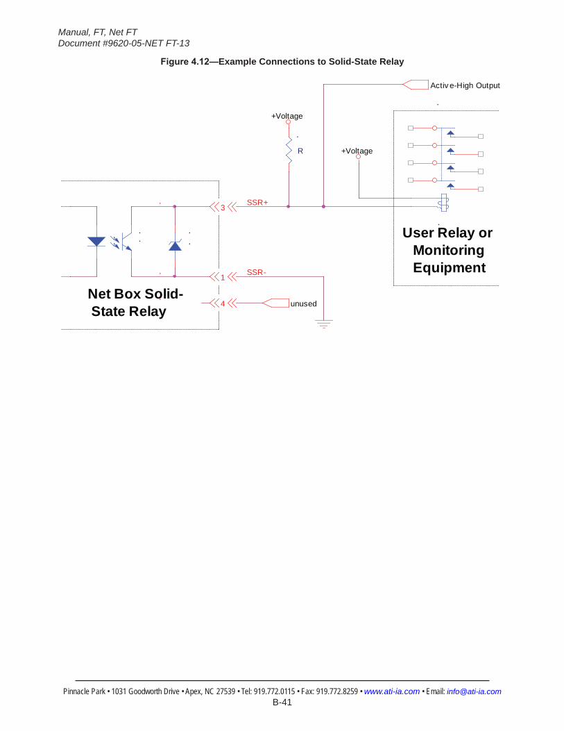
Manual, FT, Net FTDocument #9620-05-NET FT-13
Pinnacle Park • 1031 Goodworth Drive • Apex, NC 27539 • Tel: 919.772.0115 • Fax: 919.772.8259 • www.ati-ia.com • Email: [email protected] B-41
Figure4.12—Example Connections to Solid-State Relay
Activ e-High Output
1
3SSR+
4
SSR-
unused
R
+Voltage
+Voltage
User Relay or Monitoring Equipment
Net Box Solid- State Relay

Manual, FT, Net FTDocument #9620-05-NET FT-13
Pinnacle Park • 1031 Goodworth Drive • Apex, NC 27539 • Tel: 919.772.0115 • Fax: 919.772.8259 • www.ati-ia.com • Email: [email protected] B-42
4.6 ConfigurationsPage(config.htm)This page allows you to specify the output parameters of the sensor system. Up to sixteen configurations can be defined. Changing configurations allows a different transducer calibration and tool transformation to be used. Changes on this page are not implemented until the Apply button is clicked.
Figure4.13—ConfigurationsPage
View Configuration: Selects the configuration to be viewed and edited. Clicking the Go button updates the page with the selected configuration.
Configuration Name: Defines a name for the configuration.
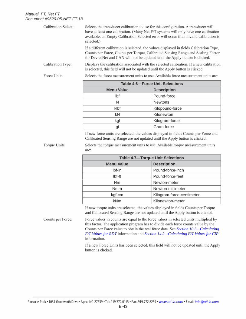
Manual, FT, Net FTDocument #9620-05-NET FT-13
Pinnacle Park • 1031 Goodworth Drive • Apex, NC 27539 • Tel: 919.772.0115 • Fax: 919.772.8259 • www.ati-ia.com • Email: [email protected] B-43
Calibration Select: Selects the transducer calibration to use for this configuration. A transducer will have at least one calibration. (Many Net F/T systems will only have one calibration available; an Empty Calibration Selected error will occur if an invalid calibration is selected.)
If a different calibration is selected, the values displayed in fields Calibration Type, Counts per Force, Counts per Torque, Calibrated Sensing Range and Scaling Factor for DeviceNet and CAN will not be updated until the Apply button is clicked.
Calibration Type: Displays the calibration associated with the selected calibration. If a new calibration is selected, this field will not be updated until the Apply button is clicked.
Force Units: Selects the force measurement units to use. Available force measurement units are:
Table 4.6—Force Unit SelectionsMenu Value Description
lbf Pound-forceN Newtons
klbf Kilopound-forcekN Kilonewtonkgf Kilogram-forcegf Gram-force
If new force units are selected, the values displayed in fields Counts per Force and Calibrated Sensing Range are not updated until the Apply button is clicked.
Torque Units: Selects the torque measurement units to use. Available torque measurement units are:
Table 4.7—Torque Unit SelectionsMenu Value Description
lbf-in Pound-force-inchlbf-ft Pound-force-feetNm Newton-meter
Nmm Newton-millimeterkgf-cm Kilogram-force-centimeterkNm Kilonewton-meter
If new torque units are selected, the values displayed in fields Counts per Torque and Calibrated Sensing Range are not updated until the Apply button is clicked.
Counts per Force: Force values in counts are equal to the force values in selected units multiplied by this factor. The application program has to divide each force counts value by the Counts per Force value to obtain the real force data. See Section 10.3—Calculating F/T Values for RDT information and Section 14.2—Calculating F/T Values for CIP information.
If a new Force Units has been selected, this field will not be updated until the Apply button is clicked.
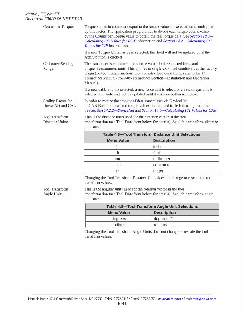
Manual, FT, Net FTDocument #9620-05-NET FT-13
Pinnacle Park • 1031 Goodworth Drive • Apex, NC 27539 • Tel: 919.772.0115 • Fax: 919.772.8259 • www.ati-ia.com • Email: [email protected] B-44
Counts per Torque: Torque values in counts are equal to the torque values in selected units multiplied by this factor. The application program has to divide each torque counts value by the Counts per Torque value to obtain the real torque data. See Section 10.3—Calculating F/T Values for RDT information and Section 14.2—Calculating F/T Values for CIP information.
If a new Torque Units has been selected, this field will not be updated until the Apply button is clicked.
Calibrated Sensing The transducer is calibrated up to these values in the selected force and Range: torque measurement units. This applies to single-axis load conditions at the factory
origin (no tool transformation). For complex load conditions, refer to the F/T Transducer Manual (9620-05-Transducer Section—Installation and Operation Manual).
If a new calibration is selected, a new force unit is select, or a new torque unit is selected, this field will not be updated until the Apply button is clicked.
Scaling Factor for In order to reduce the amount of data transmitted via DeviceNet DeviceNet and CAN: or CAN Bus, the force and torque values are reduced to 16 bits using this factor.
See Section 14.2.2—DeviceNet and Section 15.5—Calculating F/T Values for CAN.
Tool Transform This is the distance units used for the distance vector in the tool Distance Units: transformation (see Tool Transform below for details). Available transform distance
units are:
Table 4.8—Tool Transform Distance Unit SelectionsMenu Value Description
In inchft foot
mm millimetercm centimeterm meter
Changing the Tool Transform Distance Units does not change or rescale the tool transform values.
Tool Transform This is the angular units used for the rotation vector in the tool Angle Units: transformation (see Tool Transform below for details). Available transform angle
units are:
Table 4.9—ToolTransformAngleUnitSelectionsMenu Value Description
degrees degrees (°)radians radians
Changing the Tool Transform Angle Units does not change or rescale the tool transform values.

Manual, FT, Net FTDocument #9620-05-NET FT-13
Pinnacle Park • 1031 Goodworth Drive • Apex, NC 27539 • Tel: 919.772.0115 • Fax: 919.772.8259 • www.ati-ia.com • Email: [email protected] B-45
Tool Transform: Tool transform offsets are defined here. To keep the transducer’s point of origin at the factory-defined location these values need to be all zero. Descriptions of the values and the order in which the values are applied to the factory-defined point of origin are as follows:
Table 4.10—Torque Unit SelectionsColumn Description Order
Dx Distance to move X axis 1Dy Distance to move Y axis 2Dz Distance to move Z axis 3Rx Rotation angle about X axis 4Ry Rotation angle about Y axis 5Rz Rotation angle about Z axis 6
Forces and torques are by default reported with respect to the factory point of origin [The factory point of origin places the X, Y, and Z axes as shown on the transducer drawings in the F/T Transducer Manual (9620-05-Transducer Section—Installation and Operation Manual)]. The tool transformation function allows measurement of the forces and torques at some point other than the origin of the transducer. Tool transformations are particularly useful when this point is chosen as the point-of-contact between the robotic end-effector (tool) and the object being worked. A tool transformation can translate the reported origin a distance (Dx, Dy and Dz) from the factory origin and also rotate the reported origin (Rx, Ry and Rz) about the factory origin. A tool transformation allows a coordinate frame to be created that aligns resolved force/torque components with the natural axes of the task geometry.
All transducer working specifications pertain to the factory point-of-origin only. This includes the transducer’s range, resolution, and accuracy. The transducer working specifications at a customer-applied point-of-origin will differ from those at the factory point of-origin.
User-defined Field #1: Defines a short note for this configuration.
User-defined Field #2: Defines a second short note for this configuration.
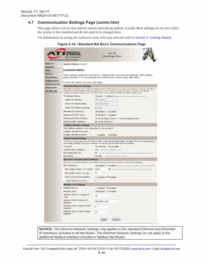
Manual, FT, Net FTDocument #9620-05-NET FT-13
Pinnacle Park • 1031 Goodworth Drive • Apex, NC 27539 • Tel: 919.772.0115 • Fax: 919.772.8259 • www.ati-ia.com • Email: [email protected] B-46
4.7 CommunicationSettingsPage(comm.htm)This page allows you to view and set system networking options. Usually these settings are set once when the system is first installed and do not need to be changed later.For information on setting the system to work with your network refer to Section 3—Getting Started.
Figure4.14—StandardNetBox’sCommunicationsPage
NOTICE: The Ethernet Network Settings only applies to the standard Ethernet and EtherNet/IP interfaces included in all Net Boxes. The Ethernet Network Settings do not apply to the additionalfieldbusinterfaceincludedinfieldbusNetBoxes.
Manual, FT, Net FTDocument #9620-05-NET FT-13
Pinnacle Park • 1031 Goodworth Drive • Apex, NC 27539 • Tel: 919.772.0115 • Fax: 919.772.8259 • www.ati-ia.com • Email: [email protected] B-47
Ethernet Network Settings:Ethernet/IP O2T Data If enabled, the Net F/T accepts a 4-byte output bitmap which is identical to the
Profinet bitmap in Table 16.3. If disabled, the Net F/T does not accept any Ethernet/IP output data.
Ethernet/IP Data Format: Changes the Ethernet/IP output data between the current 32-bit values, and 16-bit unsigned values. The 16-bit unsigned values use the same 16-bit scaling factor used by the DeviceNet, CAN, and TCP interface data (see Figure 14.1), and since they are unsigned, a “no load” value is reported as +32768 counts, a negative full-scale load is reported as approximately 0 counts, and a positive full-scale load is reported as approximately 65536 counts.
IP Address Mode: Controls how the Net F/T determines its IP Address. If DHCP is selected, it will obtain an IP address from the Ethernet network’s DHCP server. If the Net Box does not receive an address from the DHCP server within 30 seconds after power up, it will default to use the static IP settings. If Static IP is selected, the Static IP Address and Static IP Subnet Mask will be used for the IP address.
NOTICE: DHCP-assigned addresses are not permanent and may change if the Net F/T is disconnected from the network for a period of time. Contact your IT department for more information. If this occurs, you can determine the changed IP address by following the instructions in Section 6.1—Finding Net F/Ts on the Network.
Static IP addresses are often more desirable in permanent Net F/T installations because the address will not change.
Static IP Address: Sets the static IP address. Refer to Section 3.4—IP Address Configuration for Ethernet for usage details. Contact your IT department for information on what static IP address to assign.
Static IP Subnet Mask: Sets the subnet mask portion of the IP address. Many networks use the default 255.255.255.0. Contact your IT department for information on what static IP subnet mask to assign.
Static IP Default Sets the default gateway. Contact your IT department for information onGateway: what default gateway to assign.
EtherNet/IP Protocol: Controls whether or not the Net F/T uses EtherNet/IP. EtherNet/IP is only needed for industrial networks using the EtherNet/IP protocol. Most non-industrial applications will leave EtherNet/IP disabled. DeviceNet protocol must be disabled when EtherNet/IP protocol is enabled.
Ethernet MAC Address: The unique address given to this Net F/T at the time of manufacture. This address can be used to uniquely identify this Net F/T from other Net F/Ts and other Ethernet devices.
Fieldbus Module Settings (only displays on fieldbus Net Boxes):Fieldbus Module Displays the type of fieldbus protocol supported by the fieldbus Net Box.Firmware:
Fieldbus Module If enabled, the Net Box will support the fieldbus protocol listed in Fieldbus Enabled: Module Firmware. If disabled, then that fieldbus protocol is unavailable to the
network.
Manual, FT, Net FTDocument #9620-05-NET FT-13
Pinnacle Park • 1031 Goodworth Drive • Apex, NC 27539 • Tel: 919.772.0115 • Fax: 919.772.8259 • www.ati-ia.com • Email: [email protected] B-48
CAN Network Settings:Protocol: Controls which protocol will be used on the Pwr/CAN connector. When CAN Bus
is selected the basic CAN protocol described in Section 15—CAN Bus Operation is used. When DeviceNet is selected the DeviceNet-compatibility mode protocol described in Section 13—DeviceNet-Compatibility Mode Operation is used. It is best to select CAN Bus when neither protocol is needed; otherwise a DeviceNet protocol failure will be signaled. EtherNet/IP protocol must be disabled when DeviceNet protocol is enabled.
CAN Bus Base Displays the base address to be used by the CAN bus protocol.Address: See Section 3.9.2—Node Address for information on setting this address.
DeviceNet MAC ID: Displays the DeviceNet MAC ID address to be used by the DeviceNet compatibility-mode protocol. See Section 3.9.2—Node Address for information on setting this address.
Baud Rate: Displays the CAN bus baud rate used by the CAN network. See Section 3.9.3—Baud Rate for information on setting the baud rate.
NOTICE: The values displayed for CAN Bus Base Address, DeviceNet MAC ID, and Baud Rate are only valid if power is supplied to the Pwr/CAN connector. Otherwise indeterminate data is displayed.
Raw Data Transfer (RDT) Settings:RDT Interface: If enabled, the Net Box will be allowed to establish a point-to-point UDP
connection to a host computer. This is the fastest way to read F/T data from the sensor system. In Section 10—UDP Interface Using RDT the RDT interface is described in detail. RDT data is routed through the local network and does not get routed through the default gateway.
RDT Output Rate: The rate per second at which the Net Box will send streaming RDT data to a host. It can be adjusted in integer fractions of 7000. (e.g., 7000÷2=3500 or 7000÷3=2333). If you enter a different sample rate, the Net F/T will automatically change to the next higher possible sample rate.
RDT Buffer Size: The RDT interface can operate in different modes. One of these is the Buffer Mode where the Net Box sends more than one data package per sample. Multiple data packages are buffered and sent in one block. This reduces the amount of overhead data to be sent with the effect of reducing the overall network traffic. The number of data sets per block is the Buffer Mode Size.
Multi-Unit If enabled, the Net Box will synchronize its RDT data output with other NetSynchronization: F/T sensor systems on the same network. In a network with only one sensor system,
this option should be disabled. Refer to Section 10.4—Multi-Unit Mode for details. Multi-Unit IDs must be assigned for this to work correctly.
Multi-Unit ID: If Multi-Unit Synchronization is enabled, each Net F/T using multi-unit synchronization needs to have a unique ID assigned to it.

Manual, FT, Net FTDocument #9620-05-NET FT-13
Pinnacle Park • 1031 Goodworth Drive • Apex, NC 27539 • Tel: 919.772.0115 • Fax: 919.772.8259 • www.ati-ia.com • Email: [email protected] B-49
Modbus TCP Settings:Modbus Server: The internal TCP Modbus Server is active whenever it is selected on the Modbus
Setting portion of the Communications screen. The Modbus Server supports the following Modbus commands:
• Read Input Registers
• Read Holding Registers
• Write Single Register
• Write Multiple Registers
• Read/Write Multiple Registers
Modbus Client: The internal TCP Modbus Client is active whenever it is selected on the Modbus Setting portion of the Communications screen.
Every “Modbus Client’s Tx Interval” milliseconds the Modbus Client uses the Modbus Read/Write Multiple Registers command to write its internal registers 0 through 26 to the remote Modbus Server registers starting with the register number specified by “Modbus Client’s Server Write Register”. In the same command, it also reads its internal registers 27 to 42 from those in the remote Modbus Server starting with the register number specified by “Modbus Client’s Server Read Register”. The remote Modbus Server is located at the Modbus Client’s Server IP Address.
If the remote Modbus Server reports that it does not support the Modbus Read/Write Multiple Registers command, the register transfers are instead done from then on using the Read Holding Registers and the Write Multiple Registers commands.

Manual, FT, Net FTDocument #9620-05-NET FT-13
Pinnacle Park • 1031 Goodworth Drive • Apex, NC 27539 • Tel: 919.772.0115 • Fax: 919.772.8259 • www.ati-ia.com • Email: [email protected] B-50
4.7.1 TCPModbusRegisterMapTable 4.11—TCPModbusRegisterMap
NetBoxRegister CorrespondingRobotRegister Direction(fromNetBox) Function0 128 Out Force X1 129 Out Force Y2 130 Out Force Z3 131 Out Torque X4 132 Out Torque Y5 133 Out Torque Z6 134 Out Status MSB7 135 Out Status LSB8 136 Out Gage 09 137 Out Gage 1
10 138 Out Gage 211 139 Out Gage 312 140 Out Gage 413 141 Out Gage 514 142 Out Force Units15 143 Out Torque Units16 144 Out Scale Factor 017 145 Out Scale Factor 118 146 Out Scale Factor 219 147 Out Scale Factor 320 148 Out Scale Factor 421 149 Out Scale Factor 522 150 Out Counts per Force MSW23 151 Out Counts per Force LSW24 152 Out Counts per Torque MSW25 153 Out Counts per Torque LSW26 154 Out Sequence Number27 155 In System Commands28 156 In Transform Distance Units29 157 In Transform Angle Units30 158 In Dx * 10031 159 In Dy * 10032 160 In Dz * 10033 161 In Rx * 10034 162 In Ry * 10035 163 In Rz * 10036 164 In MCEnable LSW37 165 In MCEnable MSW38 166 In WMC index39 167 In WMC axis40 168 In WMC output code41 169 In WMC comparison42 170 In WMC compare value
Note: The choice of writing NetBox registers 0 to 26 to UR registers 128 to 154 (and of reading UR registers 155 to 170 into NetBox registers 27 to 42) was arbitrary, and could have used any available set of contiguous UR registers of the same length. If you change Modbus register assignments, make sure that you make the corresponding register number changes in the Demo programs.
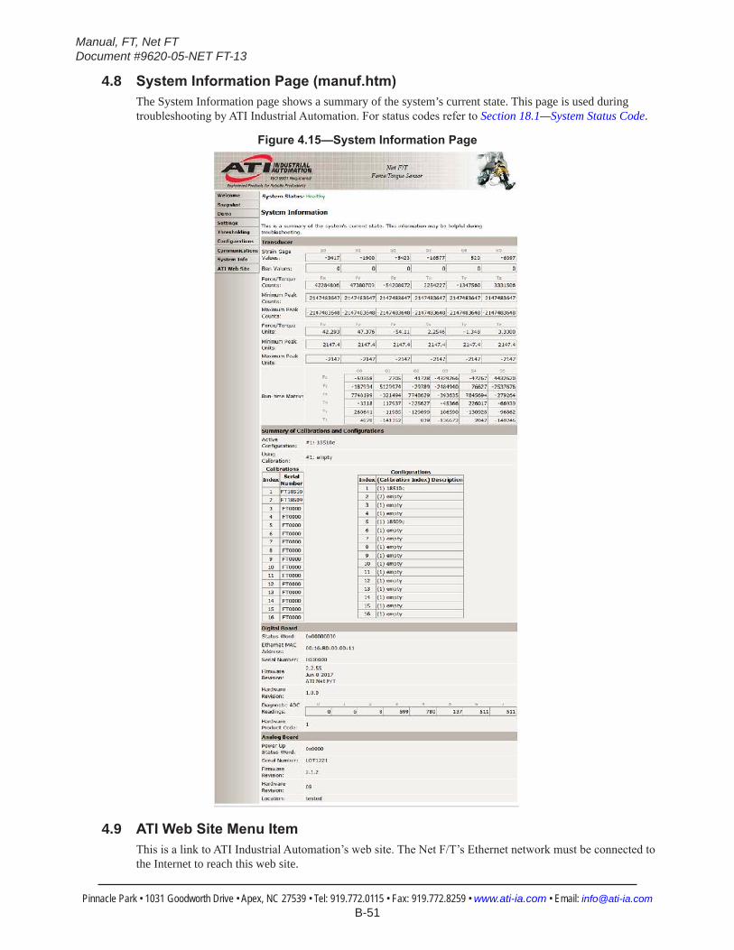
Manual, FT, Net FTDocument #9620-05-NET FT-13
Pinnacle Park • 1031 Goodworth Drive • Apex, NC 27539 • Tel: 919.772.0115 • Fax: 919.772.8259 • www.ati-ia.com • Email: [email protected] B-51
4.8 SystemInformationPage(manuf.htm)The System Information page shows a summary of the system’s current state. This page is used during troubleshooting by ATI Industrial Automation. For status codes refer to Section 18.1—System Status Code.
Figure4.15—SystemInformationPage
4.9 ATIWebSiteMenuItemThis is a link to ATI Industrial Automation’s web site. The Net F/T’s Ethernet network must be connected to the Internet to reach this web site.
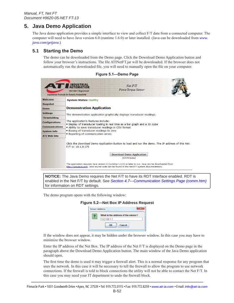
Manual, FT, Net FTDocument #9620-05-NET FT-13
Pinnacle Park • 1031 Goodworth Drive • Apex, NC 27539 • Tel: 919.772.0115 • Fax: 919.772.8259 • www.ati-ia.com • Email: [email protected] B-52
5. Java Demo ApplicationThe Java demo application provides a simple interface to view and collect F/T data from a connected computer. The computer will need to have Java version 6.0 (runtime 1.6.0) or later installed. (Java can be downloaded from www.java.com/getjava.)
5.1 StartingtheDemoThe demo can be downloaded from the Demo page. Click the Download Demo Application button and follow your browser’s instructions. The file ATINetFT.jar will be downloaded. If the browser does not automatically run the downloaded file, you will need to manually open the file on your computer.
Figure5.1—DemoPage
NOTICE: The Java Demo requires the Net F/T to have its RDT Interface enabled. RDT is enabled in the Net F/T by default. See Section 4.7—Communication Settings Page (comm.htm) for information on RDT settings.
The demo program opens with the following window:
Figure5.2—Net Box IP Address Request
If the window does not appear, it may be hidden under the browser window. In this case you may have to minimize the browser window.Enter the IP address of the Net Box. The IP address of the Net F/T is displayed on the Demo page in the paragraph above the Download Demo Application button. The main window of the Java Demo application should open.The first time the demo is used it may trigger a firewall alert. This is a normal response for any program that uses the network. In this case it will be necessary to tell the firewall to allow the program to use network connections. If the firewall is told to block connections the utility will not be able to contact the Net F/T. In this case you may need your IT department to undo the firewall block.
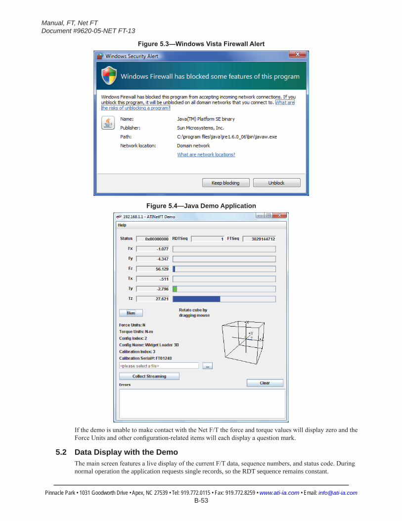
Manual, FT, Net FTDocument #9620-05-NET FT-13
Pinnacle Park • 1031 Goodworth Drive • Apex, NC 27539 • Tel: 919.772.0115 • Fax: 919.772.8259 • www.ati-ia.com • Email: [email protected] B-53
Figure5.3—WindowsVistaFirewallAlert
Figure5.4—Java Demo Application
If the demo is unable to make contact with the Net F/T the force and torque values will display zero and the Force Units and other configuration-related items will each display a question mark.
5.2 Data Display with the DemoThe main screen features a live display of the current F/T data, sequence numbers, and status code. During normal operation the application requests single records, so the RDT sequence remains constant.
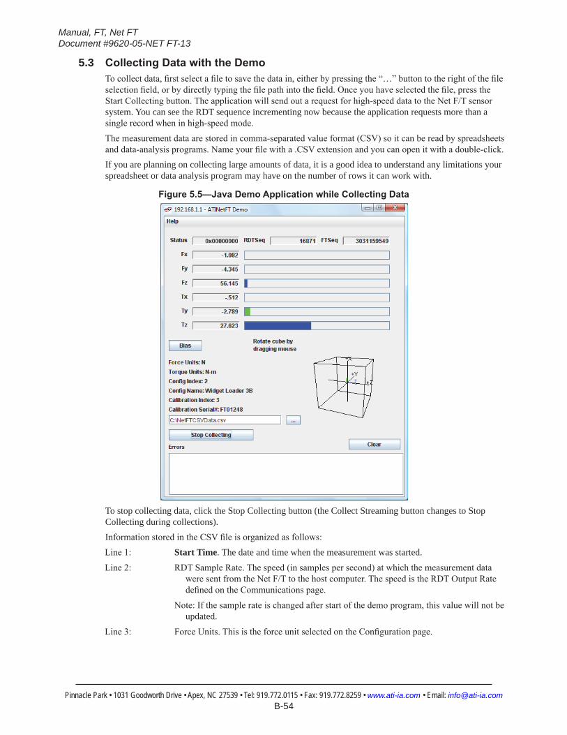
Manual, FT, Net FTDocument #9620-05-NET FT-13
Pinnacle Park • 1031 Goodworth Drive • Apex, NC 27539 • Tel: 919.772.0115 • Fax: 919.772.8259 • www.ati-ia.com • Email: [email protected] B-54
5.3 CollectingDatawiththeDemoTo collect data, first select a file to save the data in, either by pressing the “…” button to the right of the file selection field, or by directly typing the file path into the field. Once you have selected the file, press the Start Collecting button. The application will send out a request for high-speed data to the Net F/T sensor system. You can see the RDT sequence incrementing now because the application requests more than a single record when in high-speed mode.The measurement data are stored in comma-separated value format (CSV) so it can be read by spreadsheets and data-analysis programs. Name your file with a .CSV extension and you can open it with a double-click.If you are planning on collecting large amounts of data, it is a good idea to understand any limitations your spreadsheet or data analysis program may have on the number of rows it can work with.
Figure5.5—JavaDemoApplicationwhileCollectingData
To stop collecting data, click the Stop Collecting button (the Collect Streaming button changes to Stop Collecting during collections).Information stored in the CSV file is organized as follows:Line 1: Start Time. The date and time when the measurement was started.
Line 2: RDT Sample Rate. The speed (in samples per second) at which the measurement data were sent from the Net F/T to the host computer. The speed is the RDT Output Rate defined on the Communications page.
Note: If the sample rate is changed after start of the demo program, this value will not be updated.
Line 3: Force Units. This is the force unit selected on the Configuration page.
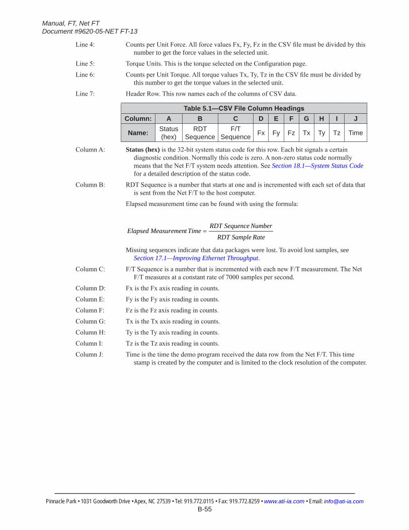
Manual, FT, Net FTDocument #9620-05-NET FT-13
Pinnacle Park • 1031 Goodworth Drive • Apex, NC 27539 • Tel: 919.772.0115 • Fax: 919.772.8259 • www.ati-ia.com • Email: [email protected] B-55
Line 4: Counts per Unit Force. All force values Fx, Fy, Fz in the CSV file must be divided by this number to get the force values in the selected unit.
Line 5: Torque Units. This is the torque selected on the Configuration page.
Line 6: Counts per Unit Torque. All torque values Tx, Ty, Tz in the CSV file must be divided by this number to get the torque values in the selected unit.
Line 7: Header Row. This row names each of the columns of CSV data.
Table 5.1—CSVFileColumnHeadingsColumn: A B C D E F G H I J
Name: Status (hex)
RDT Sequence
F/T Sequence Fx Fy Fz Tx Ty Tz Time
Column A: Status (hex) is the 32-bit system status code for this row. Each bit signals a certain diagnostic condition. Normally this code is zero. A non-zero status code normally means that the Net F/T system needs attention. See Section 18.1—System Status Code for a detailed description of the status code.
Column B: RDT Sequence is a number that starts at one and is incremented with each set of data that is sent from the Net F/T to the host computer.
Elapsed measurement time can be found with using the formula:
RateSampleRDT
NumberSequenceRDTTimetMeasuremenElapsed =
Missing sequences indicate that data packages were lost. To avoid lost samples, see Section 17.1—Improving Ethernet Throughput.
Column C: F/T Sequence is a number that is incremented with each new F/T measurement. The Net F/T measures at a constant rate of 7000 samples per second.
Column D: Fx is the Fx axis reading in counts.
Column E: Fy is the Fy axis reading in counts.
Column F: Fz is the Fz axis reading in counts.
Column G: Tx is the Tx axis reading in counts.
Column H: Ty is the Ty axis reading in counts.
Column I: Tz is the Tz axis reading in counts.
Column J: Time is the time the demo program received the data row from the Net F/T. This time stamp is created by the computer and is limited to the clock resolution of the computer.
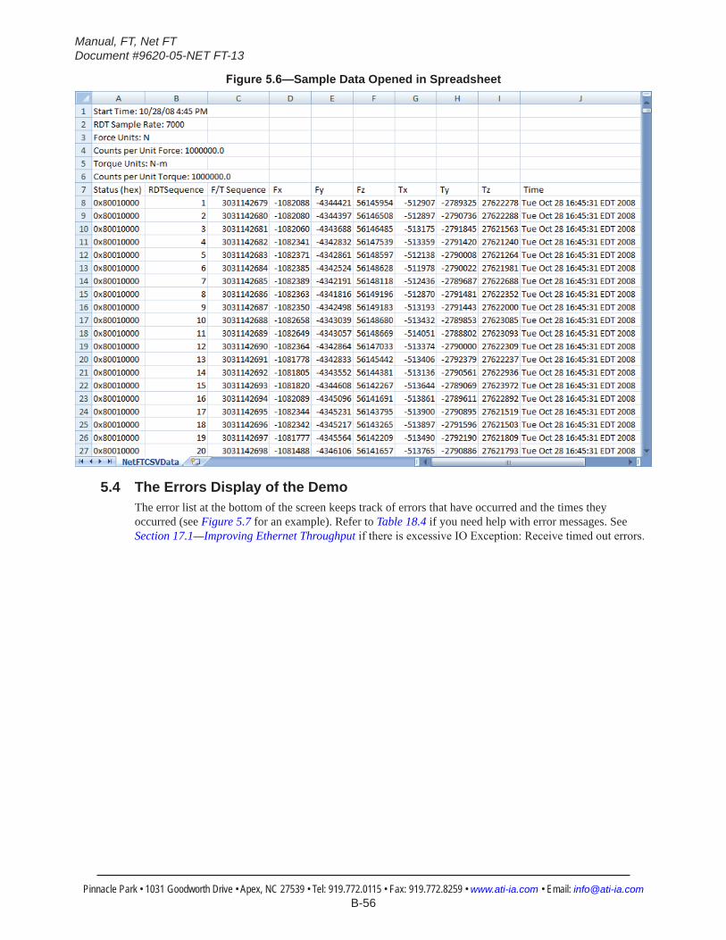
Manual, FT, Net FTDocument #9620-05-NET FT-13
Pinnacle Park • 1031 Goodworth Drive • Apex, NC 27539 • Tel: 919.772.0115 • Fax: 919.772.8259 • www.ati-ia.com • Email: [email protected] B-56
Figure5.6—Sample Data Opened in Spreadsheet
5.4 The Errors Display of the DemoThe error list at the bottom of the screen keeps track of errors that have occurred and the times they occurred (see Figure 5.7 for an example). Refer to Table 18.4 if you need help with error messages. See Section 17.1—Improving Ethernet Throughput if there is excessive IO Exception: Receive timed out errors.
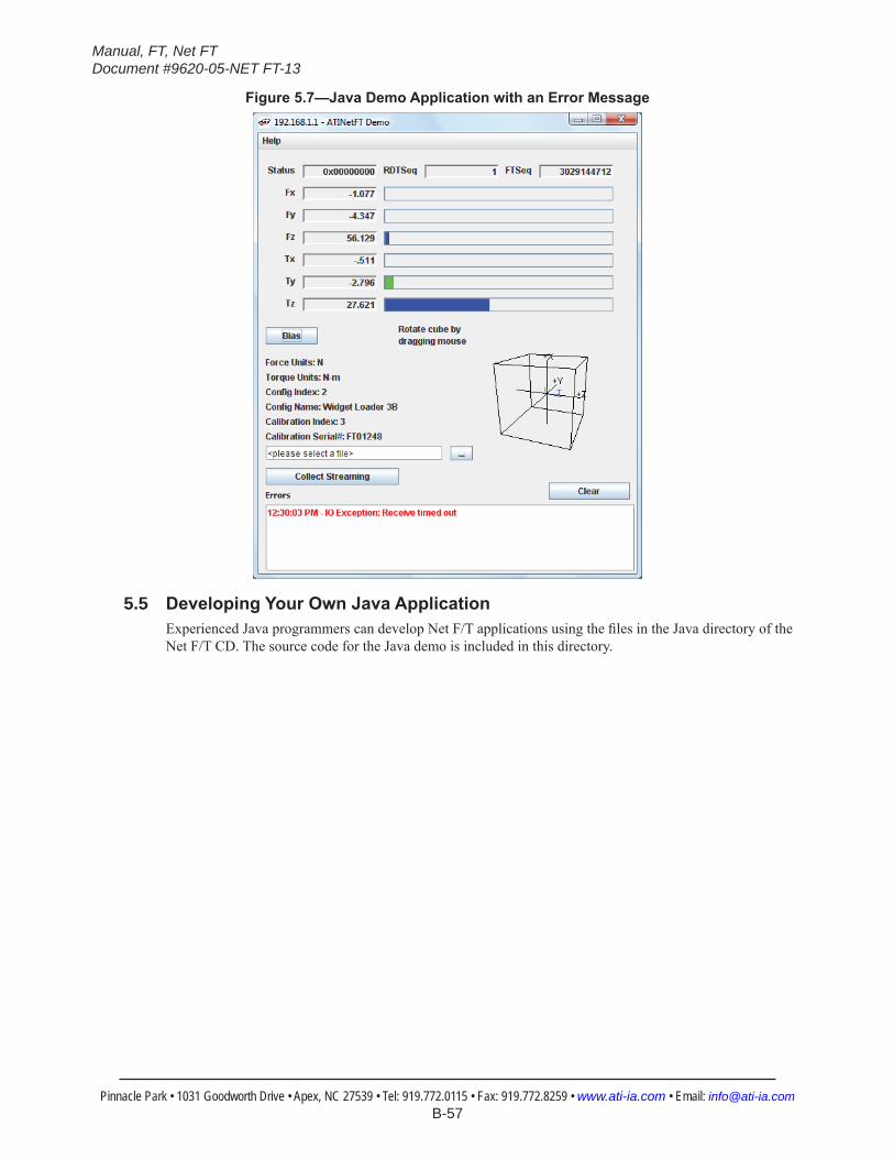
Manual, FT, Net FTDocument #9620-05-NET FT-13
Pinnacle Park • 1031 Goodworth Drive • Apex, NC 27539 • Tel: 919.772.0115 • Fax: 919.772.8259 • www.ati-ia.com • Email: [email protected] B-57
Figure5.7—JavaDemoApplicationwithanErrorMessage
5.5 DevelopingYourOwnJavaApplicationExperienced Java programmers can develop Net F/T applications using the files in the Java directory of the Net F/T CD. The source code for the Java demo is included in this directory.

Manual, FT, Net FTDocument #9620-05-NET FT-13
Pinnacle Park • 1031 Goodworth Drive • Apex, NC 27539 • Tel: 919.772.0115 • Fax: 919.772.8259 • www.ati-ia.com • Email: [email protected] B-58
6. NetF/TConfigurationUtilityThe Net F/T Configuration Utility is a Windows program that can find Net F/Ts on an Ethernet network, back up configurations to a computer, restore configurations, and display saved configuration files.
The utility’s installation package is in the Utilities directory of the Net F/T CD. Install the file by opening the NetFT_Configuration_Utility_Setup.msi file. The utility will be installed in the ATI Industrial Automation item in the program lists of Windows’ Start menu.
6.1 FindingNetF/TsontheNetworkLaunch Net F/T Configuration Utility. Click the Find Net F/T button.
Figure6.1—NetF/TConfigurationUtility
If your system has multiple connections to Ethernet a Select Connection window will appear. If this is the case, click on the entry 192.168.1.100 and then click OK.
Figure6.2—SelectinganEthernetConnection
The first time the utility is used it may trigger a firewall alert. This is a normal response for any program that uses the network. In this case it will be necessary to tell the firewall to allow the program to use network connections. If the firewall is told to block connections the utility will not be able to contact the Net F/T. In this case you may need your IT department to undo the firewall block.If the firewall alert appears it is likely that the utility will not find any Net F/Ts during that search. In this case it will be necessary to click the Find Net F/T button again and start over.
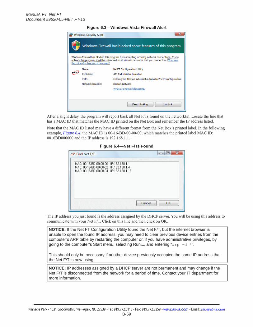
Manual, FT, Net FTDocument #9620-05-NET FT-13
Pinnacle Park • 1031 Goodworth Drive • Apex, NC 27539 • Tel: 919.772.0115 • Fax: 919.772.8259 • www.ati-ia.com • Email: [email protected] B-59
Figure6.3—WindowsVistaFirewallAlert
After a slight delay, the program will report back all Net F/Ts found on the network(s). Locate the line that has a MAC ID that matches the MAC ID printed on the Net Box and remember the IP address listed. Note that the MAC ID listed may have a different format from the Net Box’s printed label. In the following example, Figure 6.4, the MAC ID is 00-16-BD-00-00-00, which matches the printed label MAC ID: 0016BD000000 and the IP address is 192.168.1.1.
Figure6.4—Net F/Ts Found
The IP address you just found is the address assigned by the DHCP server. You will be using this address to communicate with your Net F/T. Click on this line and then click on OK.
NOTICE: IftheNetFTConfigurationUtilityfoundtheNetF/T,buttheinternetbrowserisunable to open the found IP address, you may need to clear previous device entries from the computer’s ARP table by restarting the computer or, if you have administrative privileges, by going to the computer’s Start menu, selecting Run..., and entering “arp –d *”.
This should only be necessary if another device previously occupied the same IP address that the Net F/T is now using.
NOTICE: IP addresses assigned by a DHCP server are not permanent and may change if the Net F/T is disconnected from the network for a period of time. Contact your IT department for more information.
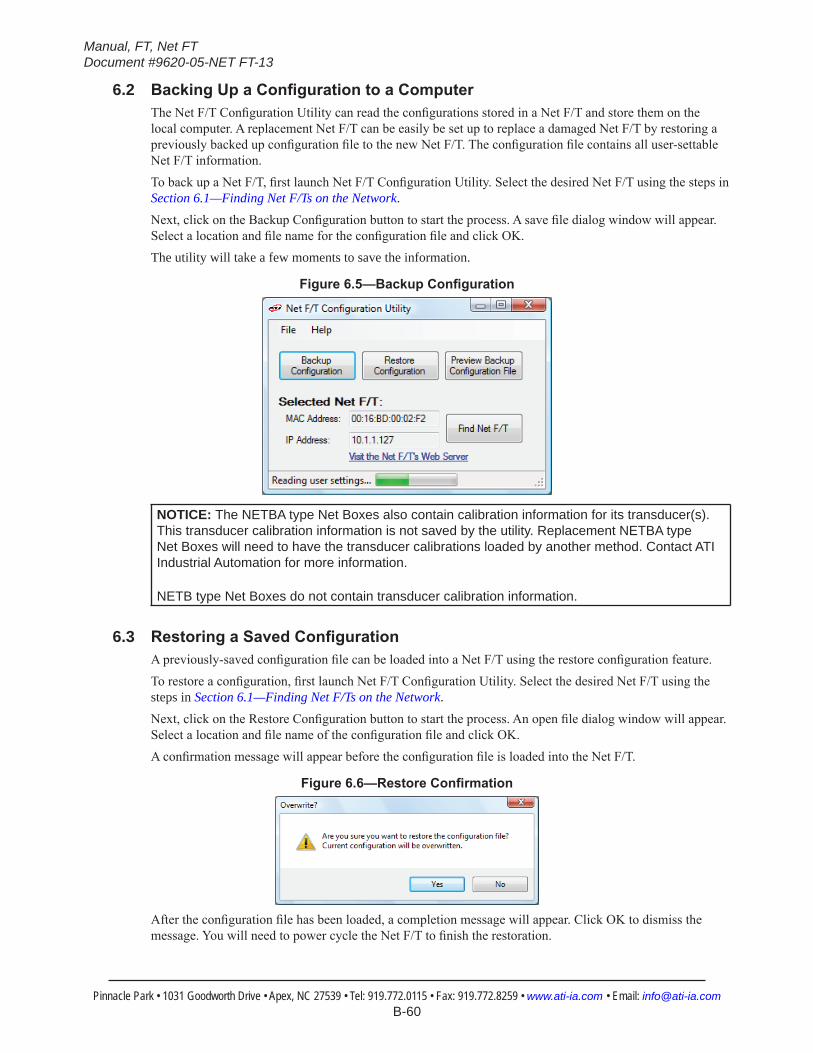
Manual, FT, Net FTDocument #9620-05-NET FT-13
Pinnacle Park • 1031 Goodworth Drive • Apex, NC 27539 • Tel: 919.772.0115 • Fax: 919.772.8259 • www.ati-ia.com • Email: [email protected] B-60
6.2 BackingUpaConfigurationtoaComputerThe Net F/T Configuration Utility can read the configurations stored in a Net F/T and store them on the local computer. A replacement Net F/T can be easily be set up to replace a damaged Net F/T by restoring a previously backed up configuration file to the new Net F/T. The configuration file contains all user-settable Net F/T information.To back up a Net F/T, first launch Net F/T Configuration Utility. Select the desired Net F/T using the steps in Section 6.1—Finding Net F/Ts on the Network.Next, click on the Backup Configuration button to start the process. A save file dialog window will appear. Select a location and file name for the configuration file and click OK.The utility will take a few moments to save the information.
Figure6.5—BackupConfiguration
NOTICE: The NETBA type Net Boxes also contain calibration information for its transducer(s). This transducer calibration information is not saved by the utility. Replacement NETBA type Net Boxes will need to have the transducer calibrations loaded by another method. Contact ATI Industrial Automation for more information.
NETB type Net Boxes do not contain transducer calibration information.
6.3 RestoringaSavedConfigurationA previously-saved configuration file can be loaded into a Net F/T using the restore configuration feature.To restore a configuration, first launch Net F/T Configuration Utility. Select the desired Net F/T using the steps in Section 6.1—Finding Net F/Ts on the Network.Next, click on the Restore Configuration button to start the process. An open file dialog window will appear. Select a location and file name of the configuration file and click OK.A confirmation message will appear before the configuration file is loaded into the Net F/T.
Figure6.6—RestoreConfirmation
After the configuration file has been loaded, a completion message will appear. Click OK to dismiss the message. You will need to power cycle the Net F/T to finish the restoration.
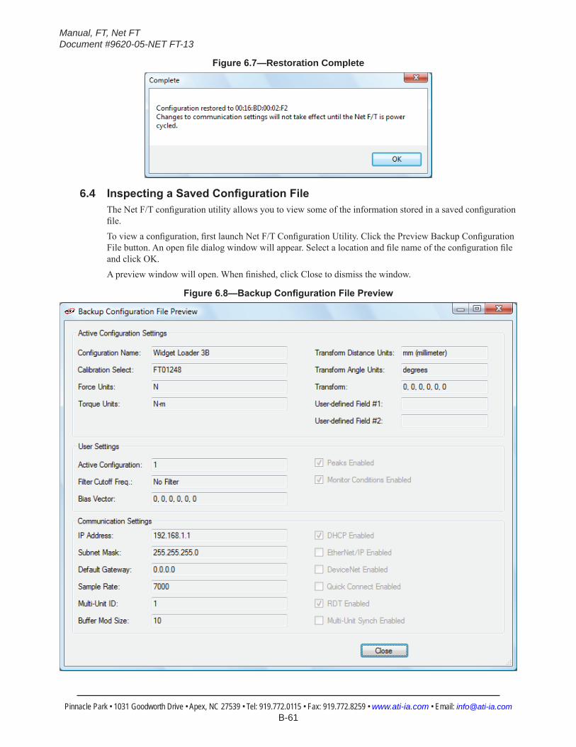
Manual, FT, Net FTDocument #9620-05-NET FT-13
Pinnacle Park • 1031 Goodworth Drive • Apex, NC 27539 • Tel: 919.772.0115 • Fax: 919.772.8259 • www.ati-ia.com • Email: [email protected] B-61
Figure6.7—Restoration Complete
6.4 InspectingaSavedConfigurationFileThe Net F/T configuration utility allows you to view some of the information stored in a saved configuration file.To view a configuration, first launch Net F/T Configuration Utility. Click the Preview Backup Configuration File button. An open file dialog window will appear. Select a location and file name of the configuration file and click OK.A preview window will open. When finished, click Close to dismiss the window.
Figure6.8—BackupConfigurationFilePreview

Manual, FT, Net FTDocument #9620-05-NET FT-13
Pinnacle Park • 1031 Goodworth Drive • Apex, NC 27539 • Tel: 919.772.0115 • Fax: 919.772.8259 • www.ati-ia.com • Email: [email protected] B-62
7. Net F/T iPad ApplicationThe Net F/T iPad application can be down loaded from the App Store. Type in Net F/T iPad in the search field and search to find the application. Then install the application on your device.
The Net F/T iPad Application allows the users to connect to transducers in their network. The application will display 10 seconds of recorded the F/T readings in numeric and waveform line graph and can record that data to a file for additional processing.
Figure7.1—Initial Screen
7.1 MonitoringandDataCollectionTo find a Transducer connected to the network click the Find button a list of all available transducer will be displayed with the IP and MAC addresses in the listed. Select the desired transducer from the displayed list. The IP address of the transducer selected will be displayed to the left of the Find button.
Figure7.2—Find Transducer’s Connected to the Network
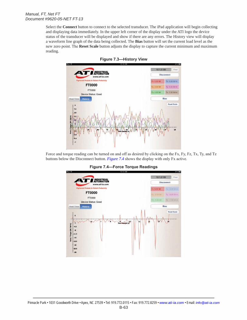
Manual, FT, Net FTDocument #9620-05-NET FT-13
Pinnacle Park • 1031 Goodworth Drive • Apex, NC 27539 • Tel: 919.772.0115 • Fax: 919.772.8259 • www.ati-ia.com • Email: [email protected] B-63
Select the Connect button to connect to the selected transducer. The iPad application will begin collecting and displaying data immediately. In the upper left corner of the display under the ATI logo the device status of the transducer will be displayed and show if there are any errors. The History view will display a waveform line graph of the data being collected. The Bias button will set the current load level as the new zero point. The Reset Scale button adjusts the display to capture the current minimum and maximum reading.
Figure7.3—History View
Force and torque reading can be turned on and off as desired by clicking on the Fx, Fy, Fz, Tx, Ty, and Tz buttons below the Disconnect button. Figure 7.4 shows the display with only Fx active.
Figure7.4—ForceTorqueReadings
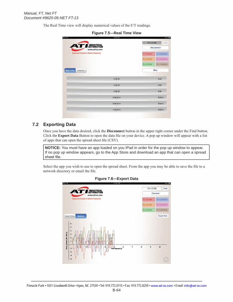
Manual, FT, Net FTDocument #9620-05-NET FT-13
Pinnacle Park • 1031 Goodworth Drive • Apex, NC 27539 • Tel: 919.772.0115 • Fax: 919.772.8259 • www.ati-ia.com • Email: [email protected] B-64
The Real Time view will display numerical values of the F/T readings.
Figure7.5—Real Time View
7.2 ExportingDataOnce you have the data desired, click the Disconnect button in the upper right corner under the Find button. Click the Export Data Button to open the data file on your device. A pop up window will appear with a list of apps that can open the spread sheet file (CSV).
NOTICE: You must have an app loaded on you iPad in order for the pop up window to appear. If no pop up window appears, go to the App Store and download an app that can open a spread sheetfile.
Select the app you wish to use to open the spread sheet. From the app you may be able to save the file to a network directory or email the file.
Figure7.6—Export Data
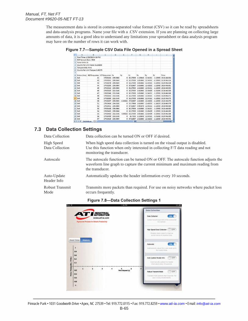
Manual, FT, Net FTDocument #9620-05-NET FT-13
Pinnacle Park • 1031 Goodworth Drive • Apex, NC 27539 • Tel: 919.772.0115 • Fax: 919.772.8259 • www.ati-ia.com • Email: [email protected] B-65
The measurement data is stored in comma-separated value format (CSV) so it can be read by spreadsheets and data-analysis programs. Name your file with a .CSV extension. If you are planning on collecting large amounts of data, it is a good idea to understand any limitations your spreadsheet or data analysis program may have on the number of rows it can work with.
Figure7.7—Sample CSV Data File Opened in a Spread Sheet
7.3 DataCollectionSettingsData Collection Data collection can be turned ON or OFF if desired.
High Speed When high speed data collection is turned on the visual output is disabled. Data Collection Use this function when only interested in collecting F/T data reading and not
monitoring the transducer.
Autoscale The autoscale function can be turned ON or OFF. The autoscale function adjusts the waveform line graph to capture the current minimum and maximum reading from the transducer.
Auto-Update Automatically updates the header information every 10 seconds.Header Info
Robust Transmit Transmits more packets than required. For use on noisy networks where packet loss Mode occurs frequently.
Figure7.8—DataCollectionSettings1

Manual, FT, Net FTDocument #9620-05-NET FT-13
Pinnacle Park • 1031 Goodworth Drive • Apex, NC 27539 • Tel: 919.772.0115 • Fax: 919.772.8259 • www.ati-ia.com • Email: [email protected] B-66
Display Dropped Displays how many packets are dropped.Packets
Reset Settings Clears all stored settings and IP addresses.
Stored IP Address Displays the stored IP address.Version Displays the Net F/T iPad application software version.
Figure7.9—DataCollectionSettings2
Manual, FT, Net FTDocument #9620-05-NET FT-13
Pinnacle Park • 1031 Goodworth Drive • Apex, NC 27539 • Tel: 919.772.0115 • Fax: 919.772.8259 • www.ati-ia.com • Email: [email protected] B-67
8. CommonGatewayInterface(CGI)The Net F/T can be configured over Ethernet using the standard HTTP get method, which sends configuration variables and their values in the requested URL.
Each variable is only settable from the CGI page which is responsible for that variable. The following tables list each CGI page and the settable variables associated with it.
URLs are constructed using the syntax:
http://<netFTAddress>/<CGIPage.cgi>?<firstVariableAssignment><&nextVariable Assignment>where:
http:// indicates an HTTP request
<netFTAddress> is the Ethernet address of the Net F/T system
/ a separator
<CGIPage.cgi> the name of the CGI page that holds the variables you will be accessing
? a separator marking the start of variable assignments
<firstVariableAssignment> a variable assignment using the format described below
<&nextVariableAssignment> a variable assignment using the format described below, but the variable name is proceeded by an ampersand. This variable assignment is optional and may be repeated for multiple variables.
Variables are assigned new values using the syntax:
variableName=newValuewhere:
variableName is the name of the variable to be assigned
= indicates assignment
newValue is the value to be assigned to the variable. Text for text variables should not be enclosed in quotes. To include the ampersand character in text for a text variable use %26. Floating point numbers are limited to twenty characters.
Example:
http://192.168.1.1/setting.cgi?setcfgsel=2&setuserfilter=0&setpke=1 tells the Net F/T at IP address 192.168.1.1 to set CGI variables setcfgsel to 2, setuserfilter to 0, and setpke to 1.
The maximum length of these URLs may be determined by a number of factors external to the Net F/T. Exceeding the maximum length may result in an error or variables being incorrectly set.
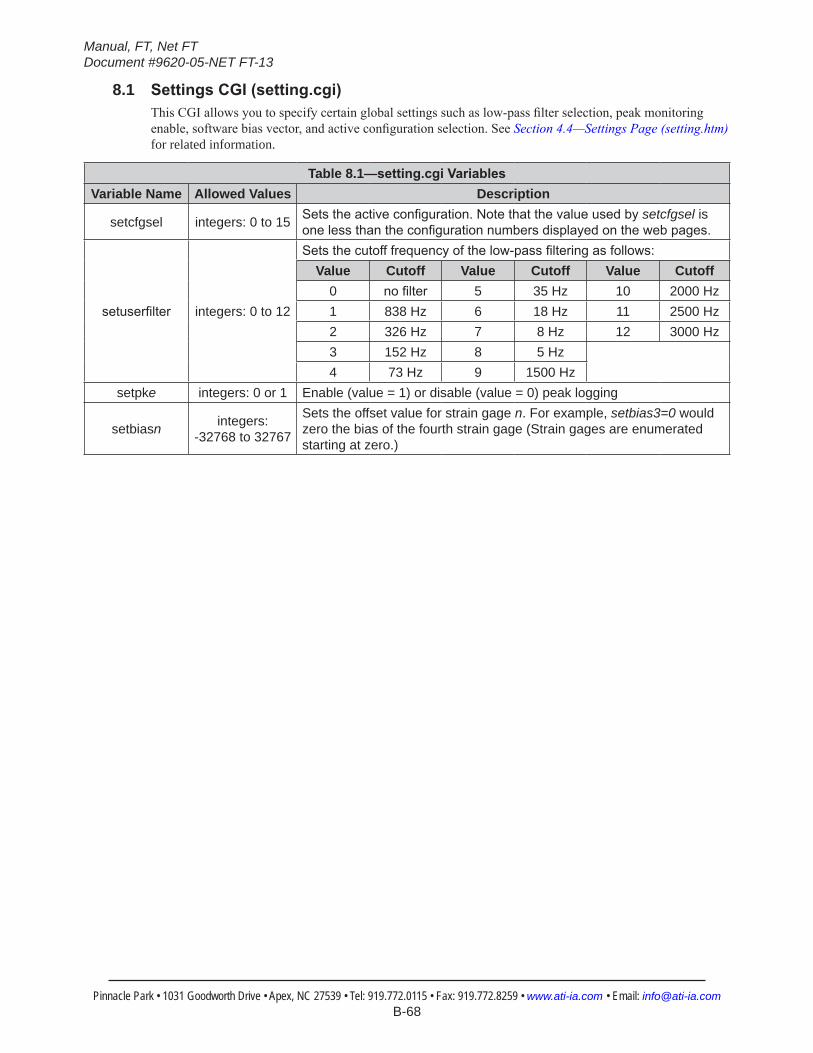
Manual, FT, Net FTDocument #9620-05-NET FT-13
Pinnacle Park • 1031 Goodworth Drive • Apex, NC 27539 • Tel: 919.772.0115 • Fax: 919.772.8259 • www.ati-ia.com • Email: [email protected] B-68
8.1 SettingsCGI(setting.cgi)This CGI allows you to specify certain global settings such as low-pass filter selection, peak monitoring enable, software bias vector, and active configuration selection. See Section 4.4—Settings Page (setting.htm) for related information.
Table 8.1—setting.cgiVariablesVariable Name Allowed Values Description
setcfgsel integers: 0 to 15 Setstheactiveconfiguration.Notethatthevalueusedbysetcfgsel is onelessthantheconfigurationnumbersdisplayedonthewebpages.
setuserfilter integers: 0 to 12
Setsthecutofffrequencyofthelow-passfilteringasfollows:Value Cutoff Value Cutoff Value Cutoff
0 nofilter 5 35 Hz 10 2000 Hz1 838 Hz 6 18 Hz 11 2500 Hz2 326 Hz 7 8 Hz 12 3000 Hz3 152 Hz 8 5 Hz4 73 Hz 9 1500 Hz
setpke integers: 0 or 1 Enable (value = 1) or disable (value = 0) peak logging
setbiasn integers: -32768 to 32767
Sets the offset value for strain gage n. For example, setbias3=0 would zero the bias of the fourth strain gage (Strain gages are enumerated starting at zero.)
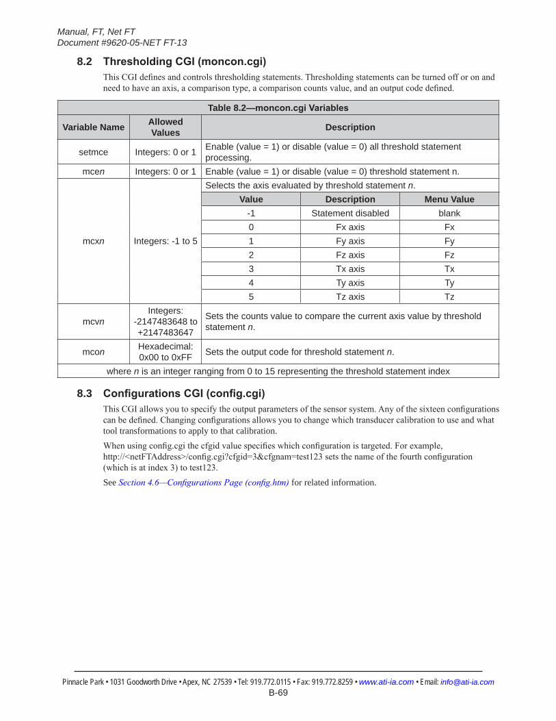
Manual, FT, Net FTDocument #9620-05-NET FT-13
Pinnacle Park • 1031 Goodworth Drive • Apex, NC 27539 • Tel: 919.772.0115 • Fax: 919.772.8259 • www.ati-ia.com • Email: [email protected] B-69
8.2 ThresholdingCGI(moncon.cgi)This CGI defines and controls thresholding statements. Thresholding statements can be turned off or on and need to have an axis, a comparison type, a comparison counts value, and an output code defined.
Table 8.2—moncon.cgiVariables
Variable Name Allowed Values Description
setmce Integers: 0 or 1 Enable (value = 1) or disable (value = 0) all threshold statement processing.
mcen Integers: 0 or 1 Enable (value = 1) or disable (value = 0) threshold statement n.
mcxn Integers: -1 to 5
Selects the axis evaluated by threshold statement n.Value Description Menu Value
-1 Statement disabled blank0 Fx axis Fx1 Fy axis Fy2 Fz axis Fz3 Tx axis Tx4 Ty axis Ty5 Tz axis Tz
mcvnIntegers:
-2147483648 to +2147483647
Sets the counts value to compare the current axis value by threshold statement n.
mcon Hexadecimal: 0x00 to 0xFF Sets the output code for threshold statement n.
where n is an integer ranging from 0 to 15 representing the threshold statement index
8.3 ConfigurationsCGI(config.cgi)This CGI allows you to specify the output parameters of the sensor system. Any of the sixteen configurations can be defined. Changing configurations allows you to change which transducer calibration to use and what tool transformations to apply to that calibration.When using config.cgi the cfgid value specifies which configuration is targeted. For example, http://<netFTAddress>/config.cgi?cfgid=3&cfgnam=test123 sets the name of the fourth configuration (which is at index 3) to test123.See Section 4.6—Configurations Page (config.htm) for related information.
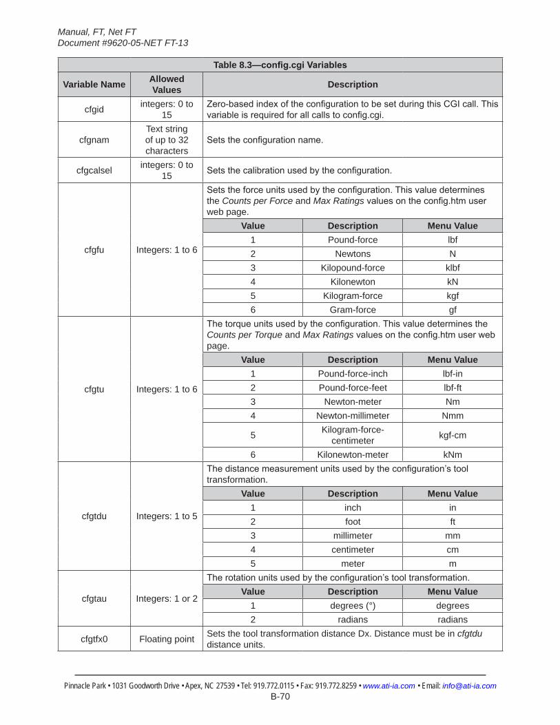
Manual, FT, Net FTDocument #9620-05-NET FT-13
Pinnacle Park • 1031 Goodworth Drive • Apex, NC 27539 • Tel: 919.772.0115 • Fax: 919.772.8259 • www.ati-ia.com • Email: [email protected] B-70
Table 8.3—config.cgiVariables
Variable Name Allowed Values Description
cfgid integers: 0 to 15
Zero-basedindexoftheconfigurationtobesetduringthisCGIcall.Thisvariableisrequiredforallcallstoconfig.cgi.
cfgnamText string of up to 32 characters
Setstheconfigurationname.
cfgcalsel integers: 0 to 15 Setsthecalibrationusedbytheconfiguration.
cfgfu Integers: 1 to 6
Setstheforceunitsusedbytheconfiguration.Thisvaluedeterminesthe Counts per Force and Max Ratingsvaluesontheconfig.htmuserweb page.
Value Description Menu Value1 Pound-force lbf2 Newtons N3 Kilopound-force klbf4 Kilonewton kN5 Kilogram-force kgf6 Gram-force gf
cfgtu Integers: 1 to 6
Thetorqueunitsusedbytheconfiguration.ThisvaluedeterminestheCounts per Torque and Max Ratingsvaluesontheconfig.htmuserwebpage.
Value Description Menu Value1 Pound-force-inch lbf-in2 Pound-force-feet lbf-ft3 Newton-meter Nm4 Newton-millimeter Nmm
5 Kilogram-force-centimeter kgf-cm
6 Kilonewton-meter kNm
cfgtdu Integers: 1 to 5
Thedistancemeasurementunitsusedbytheconfiguration’stooltransformation.
Value Description Menu Value1 inch in2 foot ft3 millimeter mm4 centimeter cm5 meter m
cfgtau Integers: 1 or 2
Therotationunitsusedbytheconfiguration’stooltransformation.Value Description Menu Value
1 degrees (°) degrees2 radians radians
cfgtfx0 Floating point Sets the tool transformation distance Dx. Distance must be in cfgtdu distance units.
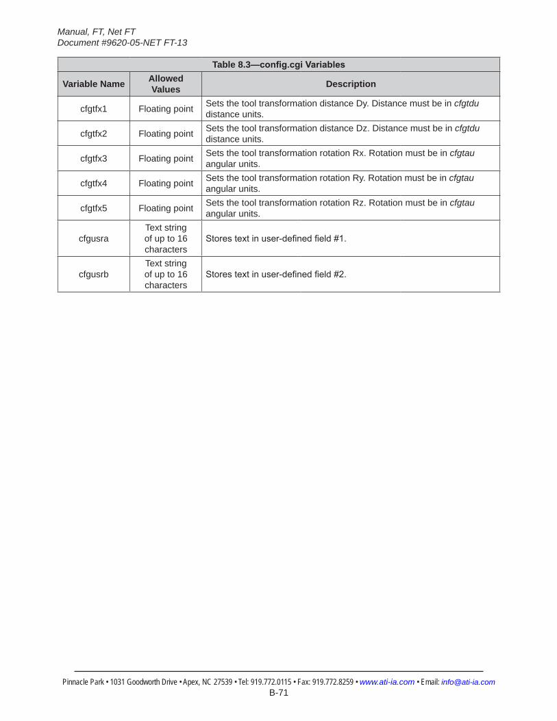
Manual, FT, Net FTDocument #9620-05-NET FT-13
Pinnacle Park • 1031 Goodworth Drive • Apex, NC 27539 • Tel: 919.772.0115 • Fax: 919.772.8259 • www.ati-ia.com • Email: [email protected] B-71
Table 8.3—config.cgiVariables
Variable Name Allowed Values Description
cfgtfx1 Floating point Sets the tool transformation distance Dy. Distance must be in cfgtdu distance units.
cfgtfx2 Floating point Sets the tool transformation distance Dz. Distance must be in cfgtdu distance units.
cfgtfx3 Floating point Sets the tool transformation rotation Rx. Rotation must be in cfgtau angular units.
cfgtfx4 Floating point Sets the tool transformation rotation Ry. Rotation must be in cfgtau angular units.
cfgtfx5 Floating point Sets the tool transformation rotation Rz. Rotation must be in cfgtau angular units.
cfgusraText string of up to 16 characters
Storestextinuser-definedfield#1.
cfgusrbText string of up to 16 characters
Storestextinuser-definedfield#2.
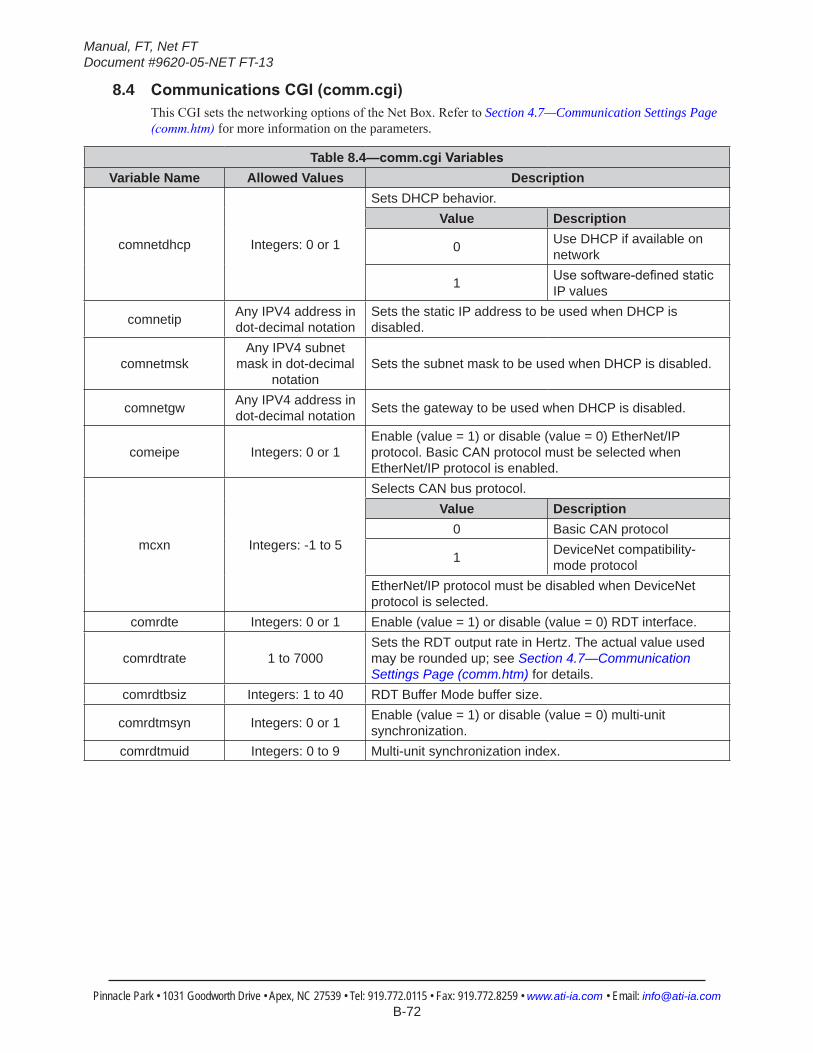
Manual, FT, Net FTDocument #9620-05-NET FT-13
Pinnacle Park • 1031 Goodworth Drive • Apex, NC 27539 • Tel: 919.772.0115 • Fax: 919.772.8259 • www.ati-ia.com • Email: [email protected] B-72
8.4 CommunicationsCGI(comm.cgi)This CGI sets the networking options of the Net Box. Refer to Section 4.7—Communication Settings Page (comm.htm) for more information on the parameters.
Table 8.4—comm.cgiVariablesVariable Name Allowed Values Description
comnetdhcp Integers: 0 or 1
Sets DHCP behavior.Value Description
0 Use DHCP if available on network
1 Usesoftware-definedstaticIP values
comnetip Any IPV4 address in dot-decimal notation
Sets the static IP address to be used when DHCP is disabled.
comnetmskAny IPV4 subnet
mask in dot-decimal notation
Sets the subnet mask to be used when DHCP is disabled.
comnetgw Any IPV4 address in dot-decimal notation Sets the gateway to be used when DHCP is disabled.
comeipe Integers: 0 or 1Enable (value = 1) or disable (value = 0) EtherNet/IP protocol. Basic CAN protocol must be selected when EtherNet/IP protocol is enabled.
mcxn Integers: -1 to 5
Selects CAN bus protocol.Value Description
0 Basic CAN protocol
1 DeviceNet compatibility-mode protocol
EtherNet/IP protocol must be disabled when DeviceNet protocol is selected.
comrdte Integers: 0 or 1 Enable (value = 1) or disable (value = 0) RDT interface.
comrdtrate 1 to 7000Sets the RDT output rate in Hertz. The actual value used may be rounded up; see Section 4.7—Communication Settings Page (comm.htm) for details.
comrdtbsiz Integers: 1 to 40 RDT Buffer Mode buffer size.
comrdtmsyn Integers: 0 or 1 Enable (value = 1) or disable (value = 0) multi-unit synchronization.
comrdtmuid Integers: 0 to 9 Multi-unit synchronization index.
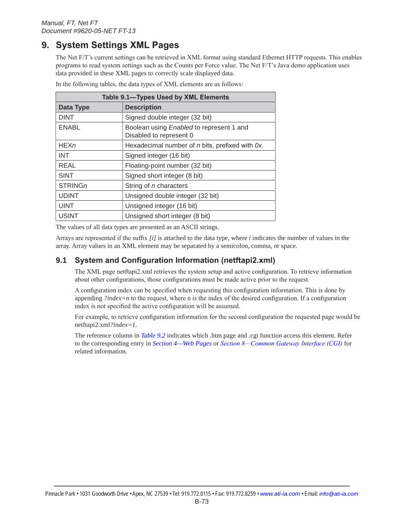
Manual, FT, Net FTDocument #9620-05-NET FT-13
Pinnacle Park • 1031 Goodworth Drive • Apex, NC 27539 • Tel: 919.772.0115 • Fax: 919.772.8259 • www.ati-ia.com • Email: [email protected] B-73
9. SystemSettingsXMLPagesThe Net F/T’s current settings can be retrieved in XML format using standard Ethernet HTTP requests. This enables programs to read system settings such as the Counts per Force value. The Net F/T’s Java demo application uses data provided in these XML pages to correctly scale displayed data.
In the following tables, the data types of XML elements are as follows:
Table 9.1—TypesUsedbyXMLElementsData Type DescriptionDINT Signed double integer (32 bit)ENABL Boolean using Enabled to represent 1 and
Disabled to represent 0HEXn Hexadecimal number of nbits,prefixedwith0x.INT Signed integer (16 bit)REAL Floating-point number (32 bit)SINT Signed short integer (8 bit)STRINGn String of n charactersUDINT Unsigned double integer (32 bit)UINT Unsigned integer (16 bit)USINT Unsigned short integer (8 bit)
The values of all data types are presented as an ASCII strings.
Arrays are represented if the suffix [i] is attached to the data type, where i indicates the number of values in the array. Array values in an XML element may be separated by a semicolon, comma, or space.
9.1 SystemandConfigurationInformation(netftapi2.xml)The XML page netftapi2.xml retrieves the system setup and active configuration. To retrieve information about other configurations, those configurations must be made active prior to the request.A configuration index can be specified when requesting this configuration information. This is done by appending ?index=n to the request, where n is the index of the desired configuration. If a configuration index is not specified the active configuration will be assumed.For example, to retrieve configuration information for the second configuration the requested page would be netftapi2.xml?index=1.The reference column in Table 9.2 indicates which .htm page and .cgi function access this element. Refer to the corresponding entry in Section 4—Web Pages or Section 8—Common Gateway Interface (CGI) for related information.

Manual, FT, Net FTDocument #9620-05-NET FT-13
Pinnacle Park • 1031 Goodworth Drive • Apex, NC 27539 • Tel: 919.772.0115 • Fax: 919.772.8259 • www.ati-ia.com • Email: [email protected] B-74
Table 9.2—XMLElementsinnetftapi2.xmlXMLElement Data Type Description Referencerunstat HEX32 System status code –runft DINT[6] Force and torque values in counts rundatarunpkmx DINT[6] Maximum peak values in counts rundatarunpkmn DINT[6] Minimum peak values in counts rundatarunsg INT[6] Strain gage values rundatarunmcb HEX32 Thresholds breached rundatarunmco HEX8 Thresholds output rundatarunmcl USINT Threshold latched rundatasetcfgsel USINT Activeconfiguration settingsetuserfilter USINT Low-passfiltercutofffrequencymenuselection settingsetpke USINT Peak monitoring processing status settingsetbias DINT[6] Software bias vector settingsetmce USINT Threshold processing status monconmce USINT[16] Threshold statements’ individual enabling monconmcx USINT[16] Threshold statements’ selected axes monconmcc USINT[16] Threshold statements’ comparisons monconmcv DINT[16] Threshold statements’ counts values for comparison monconmco HEX8[16] Threshold statements’ output codes monconcfgnam STRING32 Nameofactiveconfiguration configcfgcalsel USINT Calibrationusedbyactiveconfiguration configcfgcalsn STRING8 Serialnumberofactiveconfiguration’scalibration configcfgfu USINT Forceunitsusedbyactiveconfiguration configscfgfu STRING8 Nameofforceunitsusedbyactiveconfiguration configcfgtu USINT Torqueunitsusedbyactiveconfiguration configscfgtu STRING8 Nameoftorqueunitsusedbyactiveconfiguration config
cfgcpf DINT Countsperforceasdeterminedbytheactiveconfigurationsettings config
cfgcpt DINT Countspertorqueasdeterminedbytheactiveconfigurationsettings config
cfgmr REAL[6] Calibrated sensing ranges in units as determined by the active configurationsettings config
cfgtdu USINT Tooltransformationdistanceunitsusedbyactiveconfiguration config
scfgtdu STRING16 Name of tool transformation distance units used by active configuration config
cfgtau USINT Tooltransformationrotationunitsusedbyactiveconfiguration config
scfgtau STRING8 Name of tool transformation rotation units used by active configuration config
cfgtfx REAL[6] Tool transformation distances and rotations applied by active configuration config
cfgusra STRING16 User-definedfield#1fortheactiveconfiguration configcfgusrb STRING16 User-definedfield#2fortheactiveconfiguration configcomnetdhcp ENABL DHCP behavior setting comm
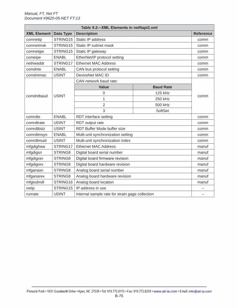
Manual, FT, Net FTDocument #9620-05-NET FT-13
Pinnacle Park • 1031 Goodworth Drive • Apex, NC 27539 • Tel: 919.772.0115 • Fax: 919.772.8259 • www.ati-ia.com • Email: [email protected] B-75
Table 9.2—XMLElementsinnetftapi2.xmlXMLElement Data Type Description Referencecomnetip STRING15 Static IP address commcomnetmsk STRING15 Static IP subnet mask commcomnetgw STRING15 Static IP gateway commcomeipe ENABL EtherNet/IP protocol setting commnethwaddr STRING17 Ethernet MAC Address commcomdnte ENABL CAN bus protocol setting commcomdntmac USINT DeviceNet MAC ID comm
comdntbaud USINT
CAN network baud rate:
comm
Value Baud Rate0 125 kHz1 250 kHz2 500 kHz3 SoftSet
comrdte ENABL RDT interface setting commcomrdtrate UDINT RDT output rate commcomrdtbsiz USINT RDT Buffer Mode buffer size commcomrdtmsyn ENABL Multi-unit synchronization setting commcomrdtmuid USINT Multi-unit synchronization index commmfgdighwa STRING17 Ethernet MAC Address manufmfgdigsn STRING8 Digital board serial number manufmfgdigver STRING8 Digitalboardfirmwarerevision manufmfgdigrev STRING8 Digital board hardware revision manufmfganasn STRING8 Analog board serial number manufmfganarev STRING8 Analog board hardware revision manufmfgtxdmdl STRING16 Analog board location manufnetip STRING15 IP address in use –runrate UDINT Internal sample rate for strain gage collection –
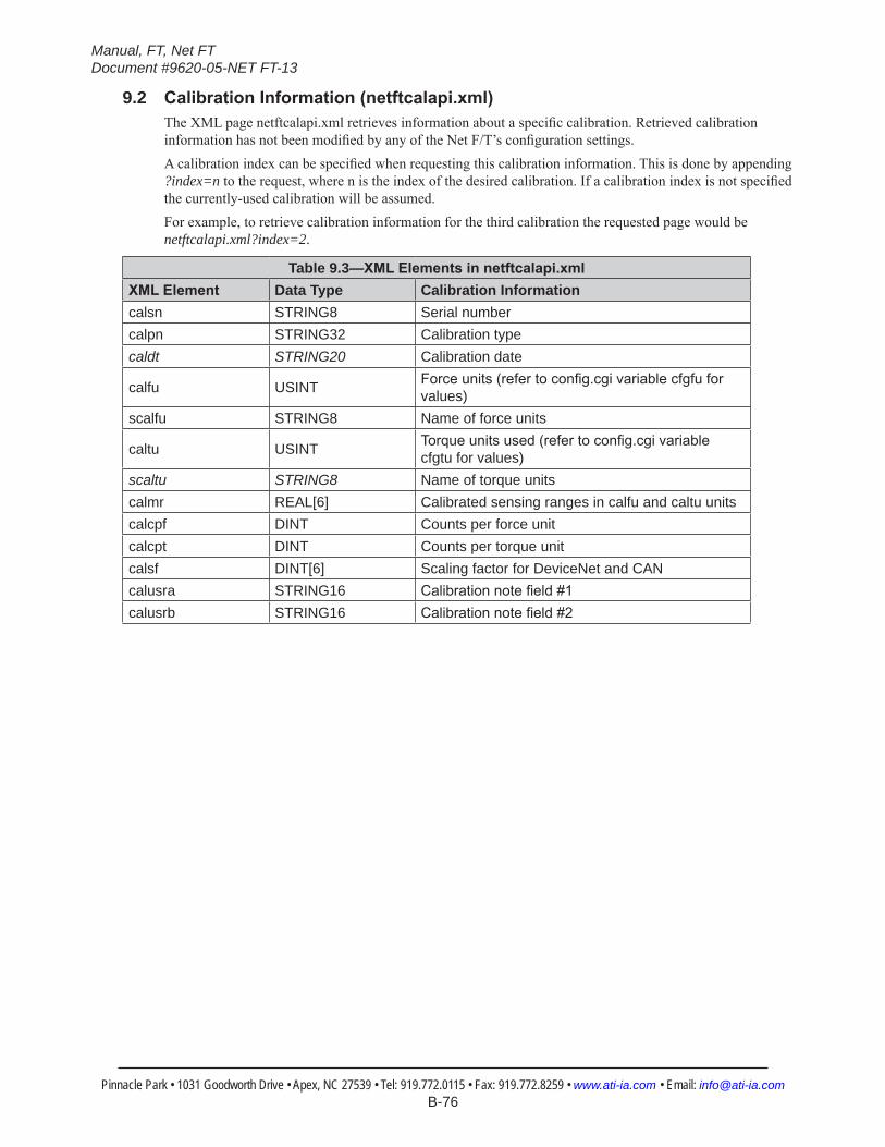
Manual, FT, Net FTDocument #9620-05-NET FT-13
Pinnacle Park • 1031 Goodworth Drive • Apex, NC 27539 • Tel: 919.772.0115 • Fax: 919.772.8259 • www.ati-ia.com • Email: [email protected] B-76
9.2 CalibrationInformation(netftcalapi.xml)The XML page netftcalapi.xml retrieves information about a specific calibration. Retrieved calibration information has not been modified by any of the Net F/T’s configuration settings.A calibration index can be specified when requesting this calibration information. This is done by appending ?index=n to the request, where n is the index of the desired calibration. If a calibration index is not specified the currently-used calibration will be assumed.For example, to retrieve calibration information for the third calibration the requested page would be netftcalapi.xml?index=2.
Table 9.3—XMLElementsinnetftcalapi.xmlXMLElement Data Type Calibration Informationcalsn STRING8 Serial numbercalpn STRING32 Calibration typecaldt STRING20 Calibration date
calfu USINT Forceunits(refertoconfig.cgivariablecfgfuforvalues)
scalfu STRING8 Name of force units
caltu USINT Torqueunitsused(refertoconfig.cgivariablecfgtu for values)
scaltu STRING8 Name of torque unitscalmr REAL[6] Calibrated sensing ranges in calfu and caltu unitscalcpf DINT Counts per force unitcalcpt DINT Counts per torque unitcalsf DINT[6] Scaling factor for DeviceNet and CANcalusra STRING16 Calibrationnotefield#1calusrb STRING16 Calibrationnotefield#2

Manual, FT, Net FTDocument #9620-05-NET FT-13
Pinnacle Park • 1031 Goodworth Drive • Apex, NC 27539 • Tel: 919.772.0115 • Fax: 919.772.8259 • www.ati-ia.com • Email: [email protected] B-77
10. UDPInterfaceUsingRDTThe Net F/T can output data at up to 7000 Hz over Ethernet using UDP. This method of fast data collection is called Raw Data Transfer (RDT). If the overhead of DeviceNet or EtherNet/IP is too much for your project, or you need extra speed in your data acquisition, RDT provides an easy method to get the forces, torques, and status codes of the Net F/T system.
NOTICE: Multi-bytevaluesmustbetransferredtothenetworkhighbytefirstandwiththecorrectnumberofbytes.Somecompilersalignstructurestolargefieldsizes,suchas32-or64-bitfields,andsend an incorrect number of bytes. C compilers usually provide the functions htons(), htonl(), ntohs(), and ntohl() that can automatically handle these issues.
10.1 RDT ProtocolThere are six commands in the RDT protocol. These are listed in Table 10.1. Any command received by the Net F/T will take precedence over any previously-received commands.
Table 10.1—RDT CommandsCommand Command Name Command Response
0x0000 Stop streaming none0x0002 Start high-speed real-time streaming RDT record(s)0x0003 Start high-speed buffered streaming RDT record(s)0x0004 Start multi-unit streaming (synchronized) RDT record(s)0x0041 Reset Threshold Latch none0x0042 Set Software Bias none
The three streaming modes are further described in Table 10.2.
Table 10.2—StreamingModesMode Command Speed Situation Best Suited To
0x0002 Start high-speed real-time streaming Fast (up to 7000 Hz) Real-time response applications.
0x0003 Start high-speed buffered streaming
Fast (up to 7000 Hz), but comes in bursts (buffers)
Collecting data at high speed, but not responding to it in real-time. Buffer size is set on the Communication Settings web page. See Section 4.7—Communication Settings Page (comm.htm).
0x0004Start multi-unit streaming (synchronized)
Slower, depending on the number of sensor systems involved
Multi-unit synchronization. The multi-unit ID number is set on the Communication Settings web page.
To start the Net F/T outputting RDT messages, you first send an RDT request to it. The Net F/T listens for RDT requests on UDP port 49152. It also sends the RDT output messages from this port.
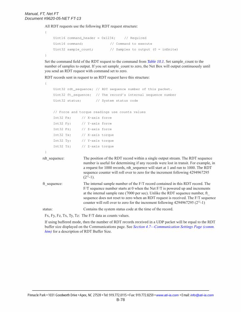
Manual, FT, Net FTDocument #9620-05-NET FT-13
Pinnacle Park • 1031 Goodworth Drive • Apex, NC 27539 • Tel: 919.772.0115 • Fax: 919.772.8259 • www.ati-ia.com • Email: [email protected] B-78
All RDT requests use the following RDT request structure:{
Uint16 command_header = 0x1234; // Required
Uint16 command; // Command to execute
Uint32sample_count; //Samplestooutput(0=infinite)
}
Set the command field of the RDT request to the command from Table 10.1. Set sample_count to the number of samples to output. If you set sample_count to zero, the Net Box will output continuously until you send an RDT request with command set to zero.RDT records sent in request to an RDT request have this structure:{
Uint32 rdt_sequence; // RDT sequence number of this packet.
Uint32 ft_sequence; // The record’s internal sequence number
Uint32 status; // System status code
// Force and torque readings use counts values
Int32 Fx; // X-axis force
Int32 Fy; // Y-axis force
Int32 Fz; // Z-axis force
Int32 Tx; // X-axis torque
Int32 Ty; // Y-axis torque
Int32 Tz; // Z-axis torque
}
rdt_sequence: The position of the RDT record within a single output stream. The RDT sequence number is useful for determining if any records were lost in transit. For example, in a request for 1000 records, rdt_sequence will start at 1 and run to 1000. The RDT sequence counter will roll over to zero for the increment following 4294967295 (232-1).
ft_sequence: The internal sample number of the F/T record contained in this RDT record. The F/T sequence number starts at 0 when the Net F/T is powered up and increments at the internal sample rate (7000 per sec). Unlike the RDT sequence number, ft_sequence does not reset to zero when an RDT request is received. The F/T sequence counter will roll over to zero for the increment following 4294967295 (232-1)
status: Contains the system status code at the time of the record.Fx, Fy, Fz, Tx, Ty, Tz: The F/T data as counts values.If using buffered mode, then the number of RDT records received in a UDP packet will be equal to the RDT buffer size displayed on the Communications page. See Section 4.7—Communication Settings Page (comm.htm) for a description of RDT Buffer Size.
Manual, FT, Net FTDocument #9620-05-NET FT-13
Pinnacle Park • 1031 Goodworth Drive • Apex, NC 27539 • Tel: 919.772.0115 • Fax: 919.772.8259 • www.ati-ia.com • Email: [email protected] B-79
10.2 Extended RDT RequestsExtended RDT requests have the following structure:{
uint16 hdr; /* Always set to 0x1234 */
uint16 cmd; /* The command code, with high bit set to ‘1’. */
uint32 count; /* The number of samples to send in response. */
uint32 ipaddr_dest; /* The ip address to send the response to. */
uint16 port_dest; /* The port to send the response to. */
}
The extended RDT request format is used when you want the Net F/T to send the UDP F/T data to a different IP address than the IP address the request comes from. This is useful, for example, if you wish to have the Net F/T stream data to a multicast address so multiple clients can receive the stream at once.The command codes used in the Extended RDT format are the same as the command codes in normal RDT requests, except that the high bit is set to a ‘1’. For example, the command code 2, for high-speed streaming, is changed to 0x8002 for use with the Extended RDT request packet structure.For example, to request high speed streaming to the multicast address 224.0.5.128, port 28250, you would send a UDP packet with the following data:
{ 0x12, 0x34, 0x80, 0x02, 0x00, 0x00, 0x00, 0x00, 224, 0, 5, 128, 0x6e, 0x5a };
Your clients can then subscribe to the UDP multicast IP address 224.0.5.128, and receive the streaming data on port 28250. Consult your client system’s documentation for information on how to subscribe to a multicast IP address.
10.3 CalculatingF/TValuesforRDTTo obtain the real force and torque values, each force output value has to be divided by the Counts per Force and each torque output value has to be divided by the Counts per Torque factor. The Counts per Force and Counts per Torque factors can be obtained from netftapi2.xml page. See cfgcpf and cfgcpt in Section 9.1—System and Configuration Information (netftapi2.xml).
10.4 Multi-Unit ModeThis mode allows multiple Net F/T systems to be used in unison. Multi-unit synchronization starts the sampling of all systems at approximately the same moment in time and then coordinate their transmissions to prevent communication collisions. Communications will remain coordinated for a time and then multi-unit synchronization will need to be stopped and restarted to resynchronize.
10.5 Multiple ClientsThe RDT protocol is designed to respond to one client only. If a second client sends a command, the Net F/T will respond to the new client. Multiple clients could repeatedly request single packets, minimizing problems. (The Java demo operates in this manner.)
Manual, FT, Net FTDocument #9620-05-NET FT-13
Pinnacle Park • 1031 Goodworth Drive • Apex, NC 27539 • Tel: 919.772.0115 • Fax: 919.772.8259 • www.ati-ia.com • Email: [email protected] B-80
10.6 Notes on UDP and RDT ModeRDT communications use UDP, with its minimal overhead, to maximize throughput. Unlike TCP, UDP does not check if a package was actually received.In some Ethernet network configurations this can lead to the loss of RDT data sets. By checking the RDT sequence number of each set, it can be determined if a data set was lost. The RDT sequence number of each data set sent will be one greater than the last data set sent for that RDT request. If a received data set’s RDT sequence number is not one greater than the last received data set, then a loss of data has occurred (the program must also account for rollover of the RDT sequence number).The likelihood of data loss highly depends on the Ethernet network configuration and there are ways to reduce the probability of data loss to almost zero. Refer to Section 17.1—Improving Ethernet Throughput for details.If there are multiple Net F/Ts on the same network, data collisions between Net F/Ts and the subsequent data losses can be eliminated by using the Net F/T’s multi-unit synchronization function.The maximum data latency, measured from the beginning of data acquisition to when the last data bit is sent to the Ethernet network, is less than 28 ms.The Net F/T only supports one UDP connection at a time.
10.7 Example CodeExample C code can be found on the ATI website at http://www.ati-ia.com/Products/ft/software/net_ft_software.aspx and on the product CD.
11. TCP Interface11.1 General
The TCP interface listens on TCP port 49151. All commands are 20 bytes in length. All responses begin with the two byte header 0x12, 0x34.
11.2 Command CodesREADFT = 0, /* Read F/T values. */
READCALINFO = 1, /* Read calibration info. */
WRITETRANSFORM = 2, /* Write tool transformation. */
WRITETHRESHOLD = 3, /* Write monitor condition. */
11.3 Read F/T Command{
uint8 command; /*MustbeREADFT(0).*/
uint8 reserved[15]; /* Should be all 0s. */
uint16 MCEnable; /* Bitmap of MCs to enable. */
uint16 sysCommands; /* Bitmap of system commands. */
}
Each bit position 0-15 in MCEnable corresponds to the monitor condition at that index. If the bit is a ‘1’, that monitor condition is enabled. If the bit is a ‘0’, that monitor condition is disabled.Bit 0 of sysCommands controls the Bias. If bit 0 is a ‘1’, the system is biased. If bit 0 is a ‘0’, no action is taken.Bit 1 of sysCommands controls the monitor condition latch. If bit 1 is a ‘1’, the monitor condition latch is cleared, and monitor condition evaluation begins again. If bit 1 is a ‘0’, no action is taken.
Manual, FT, Net FTDocument #9620-05-NET FT-13
Pinnacle Park • 1031 Goodworth Drive • Apex, NC 27539 • Tel: 919.772.0115 • Fax: 919.772.8259 • www.ati-ia.com • Email: [email protected] B-81
11.4 Read F/T Response{
uint16 header; /* always 0x1234. */
uint16 status; /* Upper 16 bits of status code. */
uint16 ForceX; /* 16-bit Force X counts. */
uint16 ForceY; /* 16-bit Force Y counts. */
uint16 ForceZ; /* 16-bit Force Z counts. */
uint16 TorqueX; /* 16-bit Torque X counts. */
uint16 TorqueY; /* 16-bit Torque Y counts. */
uint16 TorqueZ; /* 16-bit Torque Z counts. */
}
The status code is the upper 16 bits of the 32-bit status code described in the Net F/T user manual.The force and torque values in the response are equal to (actual ft value * calibration counts per unit / 16-bit scaling factor). The counts per unit and scaling factor are read using the read calibration information command.
11.5 Read Calibration Info Command{
uint8command; /*MustbeREADCALINFO(1).*/
uint8 reserved[19]; /* Should be all 0s. */
}
Manual, FT, Net FTDocument #9620-05-NET FT-13
Pinnacle Park • 1031 Goodworth Drive • Apex, NC 27539 • Tel: 919.772.0115 • Fax: 919.772.8259 • www.ati-ia.com • Email: [email protected] B-82
11.6 Read Calibration Info Response{
uint16 header; /* always 0x1234. */
uint8 forceUnits; /* Force Units. */
uint8 torqueUnits; /* Torque Units. */
uint32 countsPerForce; /* Calibration Counts per force unit. */
uint32 countsPerTorque; /* Calibration Counts per torque unit. */
uint16 scaleFactors[6]; /* Further scaling for 16-bit counts. */
}
The status code is the upper 16 bits of the 32-bit status code described in the Net F/T user manual.The force and torque values in the response are equal to (actual ft value * calibration counts per unit / 16-bit scaling factor). The counts per unit and scaling factor are read using the read calibration information command.The force unit codes are:
1: Pound
2: Newton
3: Kilopound
4: Kilonewton
5: Kilogram
6: Gram
The torque unit codes are:
1: Pound-inch
2: Pound-foot
3: Newton-meter
4: Newton-millimeter
5: Kilogram-centimeter
6: Kilonewton-meter
11.7 WriteToolTransformCommand{
uint8command;/*MustbeWRITETRANSFORM(2).*/
uint8 transformDistUnits; /* Units of dx,dy,dz */
uint8 transformAngleUnits; /* Units of rx,ry,rz */
int16 transform[6]; /* dx, dy, dz, rx, ry, rz */
uint8 reserved[5]; /* Should be all zeroes. */
}
The ‘transform’ elements are multiplied by 100 to provide good granularity with integer numbers.
The distance unit codes are:
1: Inch
2: Foot
3: Millimeter
4: Centimeter
5: Meter
The angle unit codes are:
1: Degrees
2: Radians.
The response is a standard Write Response.
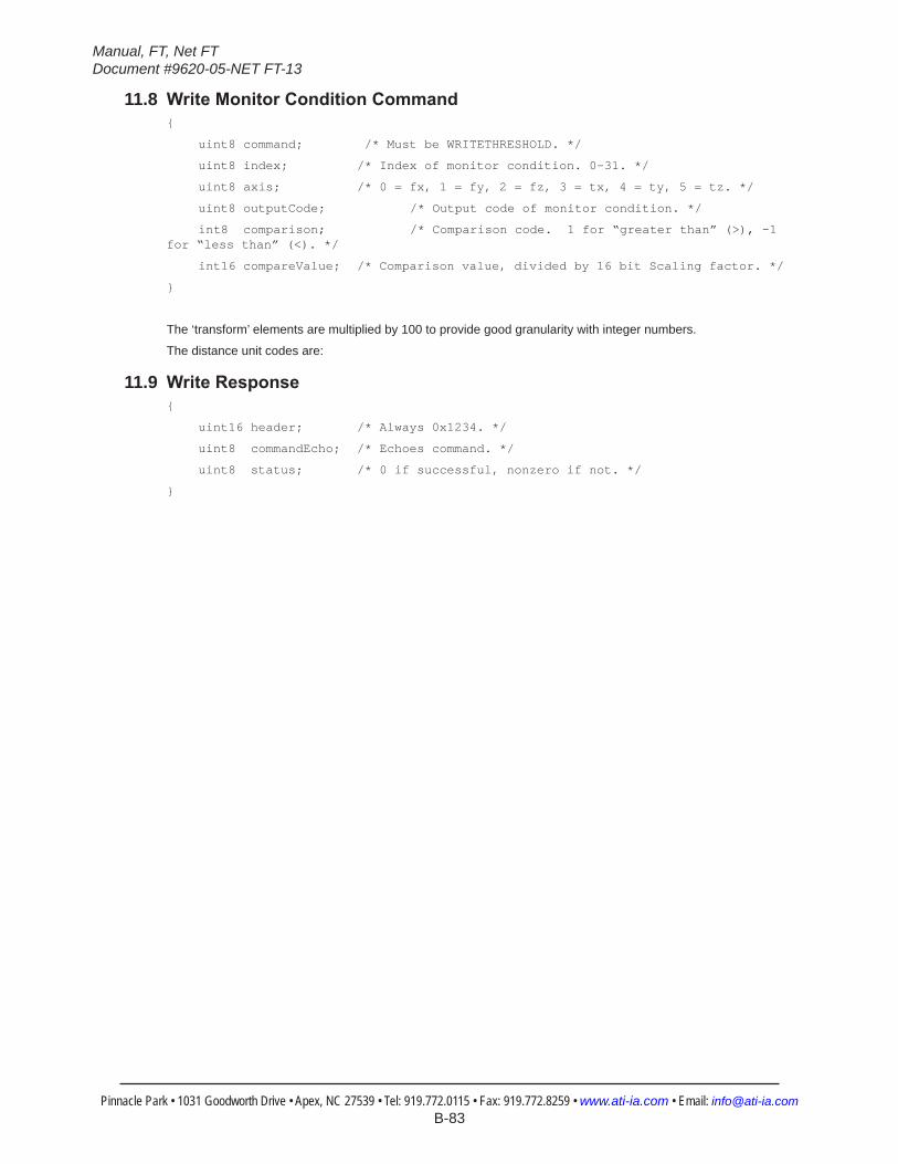
Manual, FT, Net FTDocument #9620-05-NET FT-13
Pinnacle Park • 1031 Goodworth Drive • Apex, NC 27539 • Tel: 919.772.0115 • Fax: 919.772.8259 • www.ati-ia.com • Email: [email protected] B-83
11.8 WriteMonitorConditionCommand{
uint8 command; /* Must be WRITETHRESHOLD. */
uint8 index; /* Index of monitor condition. 0-31. */
uint8 axis; /* 0 = fx, 1 = fy, 2 = fz, 3 = tx, 4 = ty, 5 = tz. */
uint8 outputCode; /* Output code of monitor condition. */
int8comparison; /*Comparisoncode.1for“greaterthan”(>),-1for“lessthan”(<).*/
int16 compareValue; /* Comparison value, divided by 16 bit Scaling factor. */
}
The ‘transform’ elements are multiplied by 100 to provide good granularity with integer numbers.
The distance unit codes are:
11.9 WriteResponse{
uint16 header; /* Always 0x1234. */
uint8 commandEcho; /* Echoes command. */
uint8 status; /* 0 if successful, nonzero if not. */
}
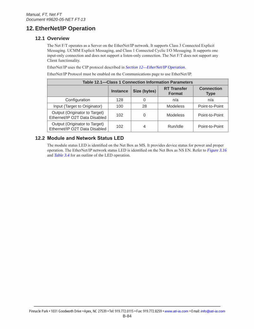
Manual, FT, Net FTDocument #9620-05-NET FT-13
Pinnacle Park • 1031 Goodworth Drive • Apex, NC 27539 • Tel: 919.772.0115 • Fax: 919.772.8259 • www.ati-ia.com • Email: [email protected] B-84
12. EtherNet/IP Operation12.1 Overview
The Net F/T operates as a Server on the EtherNet/IP network. It supports Class 3 Connected Explicit Messaging. UCMM Explicit Messaging, and Class 1 Connected Cyclic I/O Messaging. It supports one input-only connection and does not support a listen-only connection. The Net F/T does not support any Client functionality.EtherNet/IP uses the CIP protocol described in Section 12—EtherNet/IP Operation.EtherNet/IP Protocol must be enabled on the Communications page to use EtherNet/IP.
Table 12.1—Class 1 Connection Information Parameters
Instance Size(bytes) RT Transfer Format
Connection Type
Configuration 128 0 n/a n/aInput (Target to Originator) 100 28 Modeless Point-to-Point
Output (Originator to Target) Ethernet/IP O2T Data Disabled 102 0 Modeless Point-to-Point
Output (Originator to Target) Ethernet/IP O2T Data Disabled 102 4 Run/Idle Point-to-Point
12.2 ModuleandNetworkStatusLEDThe module status LED is identified on the Net Box as MS. It provides device status for power and proper operation. The EtherNet/IP network status LED is identified on the Net Box as NS EN. Refer to Figure 3.16 and Table 3.4 for an outline of the LED operation.
Manual, FT, Net FTDocument #9620-05-NET FT-13
Pinnacle Park • 1031 Goodworth Drive • Apex, NC 27539 • Tel: 919.772.0115 • Fax: 919.772.8259 • www.ati-ia.com • Email: [email protected] B-85
13. DeviceNet-Compatibility Mode Operation13.1 Overview
The Net F/T operates as a Group 2-Only Server on the DeviceNet network. It supports Explicit Messaging and Polled I/O messaging for the predefined master/Slave Connection set. The Net F/T DeviceNet Node does support the Unconnected Message Manager (UCMM).DeviceNet-compatibility mode uses the CIP protocol described in Section 14—EtherNet/IP and DeviceNet CIP Model.To use the Net F/T’s DeviceNet-Compatibility Mode, DeviceNet must be selected on the Communications page and power must be present on the Pwr/CAN connector.
13.2 MAC IDThe MAC ID is set by either hardware or software configuration to a value from 0 to 63. In order for the MAC ID to be set by software, DIP switch positions 1 through 8 must be ON. If the MAC ID is set by software, the baud rate must also be set by software. For more information refer to Section 3.9.2—Node Address and Table 3.2. The factory set MAC ID is 54.
13.3 Baud RateBaud Rate is set by either hardware or software configuration to 125 kbps, 250 kbps or 500 kbps. The baud rate will be set by software when DIP switch positions 7 and 8 are ON. For more information refer to Section 3.9.3—Baud Rate and Table 3.3. The factory set baud rate is 500 kbps.
13.4 ModuleandNetworkStatusLEDThe module status LED is identified on the Net Box as MS. It provides device status for power and proper operation. The DeviceNet network status LED is identified on the Net Box as NS DN. Refer to Figure 3.16 and Table 3.4 for an outline of the LED operation.
13.5 EDS FileThe DeviceNet EDS (Electronic Data Sheet) file for the system can be found in the \EDS directory on the system CD.
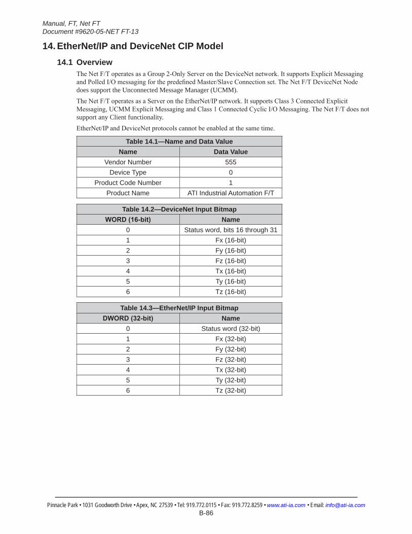
Manual, FT, Net FTDocument #9620-05-NET FT-13
Pinnacle Park • 1031 Goodworth Drive • Apex, NC 27539 • Tel: 919.772.0115 • Fax: 919.772.8259 • www.ati-ia.com • Email: [email protected] B-86
14. EtherNet/IP and DeviceNet CIP Model14.1 Overview
The Net F/T operates as a Group 2-Only Server on the DeviceNet network. It supports Explicit Messaging and Polled I/O messaging for the predefined Master/Slave Connection set. The Net F/T DeviceNet Node does support the Unconnected Message Manager (UCMM).The Net F/T operates as a Server on the EtherNet/IP network. It supports Class 3 Connected Explicit Messaging, UCMM Explicit Messaging and Class 1 Connected Cyclic I/O Messaging. The Net F/T does not support any Client functionality.EtherNet/IP and DeviceNet protocols cannot be enabled at the same time.
Table 14.1—Name and Data ValueName Data Value
Vendor Number 555Device Type 0
Product Code Number 1Product Name ATI Industrial Automation F/T
Table 14.2—DeviceNet Input BitmapWORD(16-bit) Name
0 Status word, bits 16 through 311 Fx (16-bit)2 Fy (16-bit)3 Fz (16-bit)4 Tx (16-bit)5 Ty (16-bit)6 Tz (16-bit)
Table 14.3—EtherNet/IP Input BitmapDWORD(32-bit) Name
0 Status word (32-bit)1 Fx (32-bit)2 Fy (32-bit)3 Fz (32-bit)4 Tx (32-bit)5 Ty (32-bit)6 Tz (32-bit)
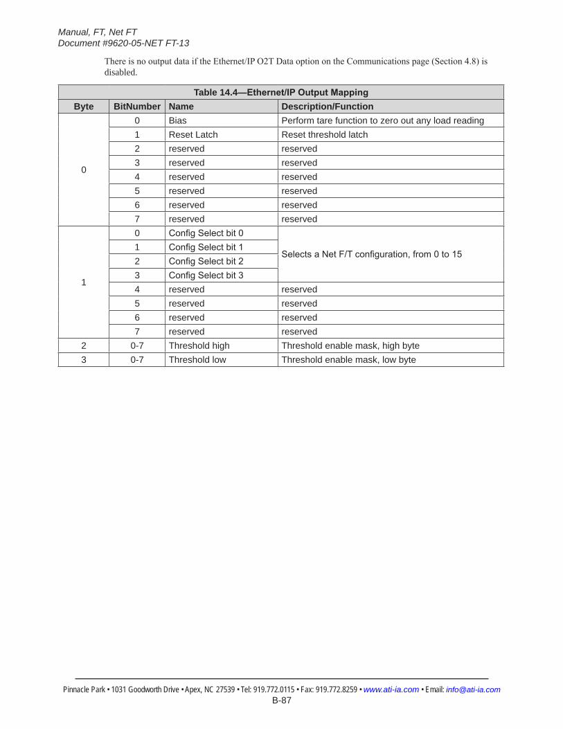
Manual, FT, Net FTDocument #9620-05-NET FT-13
Pinnacle Park • 1031 Goodworth Drive • Apex, NC 27539 • Tel: 919.772.0115 • Fax: 919.772.8259 • www.ati-ia.com • Email: [email protected] B-87
There is no output data if the Ethernet/IP O2T Data option on the Communications page (Section 4.8) is disabled.
Table 14.4—Ethernet/IPOutputMappingByte BitNumber Name Description/Function
0
0 Bias Perform tare function to zero out any load reading1 Reset Latch Reset threshold latch2 reserved reserved3 reserved reserved4 reserved reserved5 reserved reserved6 reserved reserved7 reserved reserved
1
0 ConfigSelectbit0
SelectsaNetF/Tconfiguration,from0to151 ConfigSelectbit12 ConfigSelectbit23 ConfigSelectbit34 reserved reserved5 reserved reserved6 reserved reserved7 reserved reserved
2 0-7 Threshold high Threshold enable mask, high byte3 0-7 Threshold low Threshold enable mask, low byte
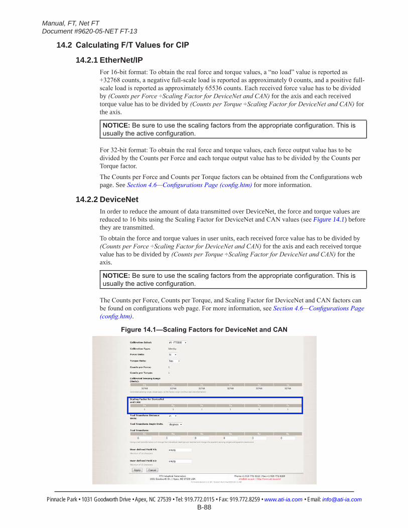
Manual, FT, Net FTDocument #9620-05-NET FT-13
Pinnacle Park • 1031 Goodworth Drive • Apex, NC 27539 • Tel: 919.772.0115 • Fax: 919.772.8259 • www.ati-ia.com • Email: [email protected] B-88
14.2 CalculatingF/TValuesforCIP
14.2.1 EtherNet/IPFor 16-bit format: To obtain the real force and torque values, a “no load” value is reported as +32768 counts, a negative full-scale load is reported as approximately 0 counts, and a positive full-scale load is reported as approximately 65536 counts. Each received force value has to be divided by (Counts per Force ÷Scaling Factor for DeviceNet and CAN) for the axis and each received torque value has to be divided by (Counts per Torque ÷Scaling Factor for DeviceNet and CAN) for the axis.
NOTICE: Besuretousethescalingfactorsfromtheappropriateconfiguration.Thisisusuallytheactiveconfiguration.
For 32-bit format: To obtain the real force and torque values, each force output value has to be divided by the Counts per Force and each torque output value has to be divided by the Counts per Torque factor.The Counts per Force and Counts per Torque factors can be obtained from the Configurations web page. See Section 4.6—Configurations Page (config.htm) for more information.
14.2.2 DeviceNet In order to reduce the amount of data transmitted over DeviceNet, the force and torque values are reduced to 16 bits using the Scaling Factor for DeviceNet and CAN values (see Figure 14.1) before they are transmitted.To obtain the force and torque values in user units, each received force value has to be divided by (Counts per Force ÷Scaling Factor for DeviceNet and CAN) for the axis and each received torque value has to be divided by (Counts per Torque ÷Scaling Factor for DeviceNet and CAN) for the axis.
NOTICE: Besuretousethescalingfactorsfromtheappropriateconfiguration.Thisisusuallytheactiveconfiguration.
The Counts per Force, Counts per Torque, and Scaling Factor for DeviceNet and CAN factors can be found on configurations web page. For more information, see Section 4.6—Configurations Page (config.htm).
Figure14.1—ScalingFactorsforDeviceNetandCAN
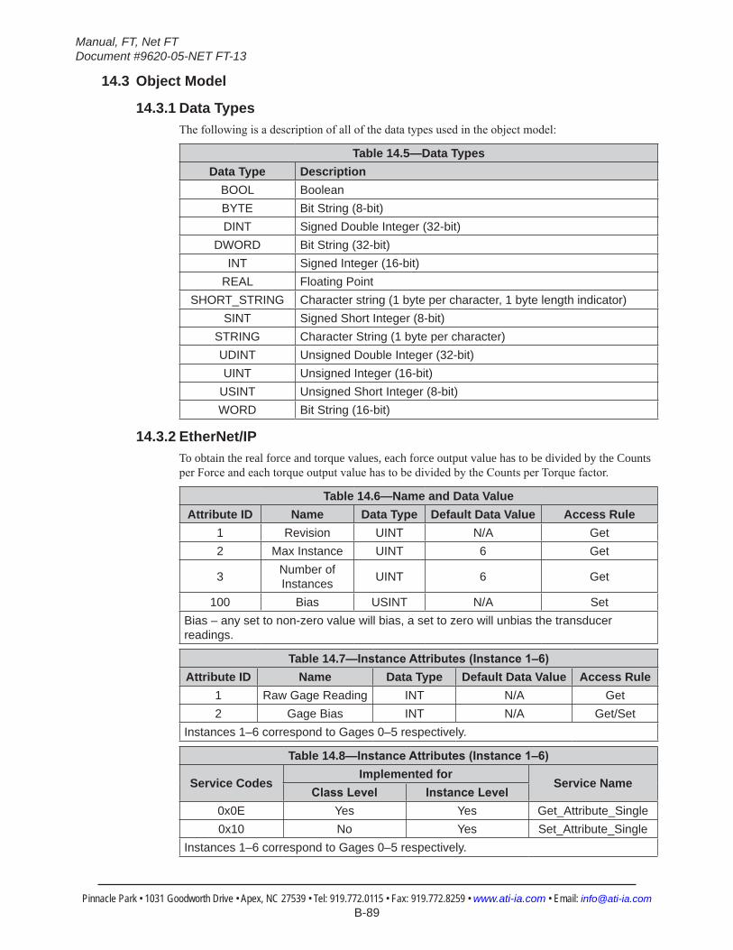
Manual, FT, Net FTDocument #9620-05-NET FT-13
Pinnacle Park • 1031 Goodworth Drive • Apex, NC 27539 • Tel: 919.772.0115 • Fax: 919.772.8259 • www.ati-ia.com • Email: [email protected] B-89
14.3 Object Model
14.3.1 Data TypesThe following is a description of all of the data types used in the object model:
Table 14.5—Data TypesData Type Description
BOOL BooleanBYTE Bit String (8-bit)DINT Signed Double Integer (32-bit)
DWORD Bit String (32-bit)INT Signed Integer (16-bit)
REAL Floating PointSHORT_STRING Character string (1 byte per character, 1 byte length indicator)
SINT Signed Short Integer (8-bit)STRING Character String (1 byte per character)UDINT Unsigned Double Integer (32-bit)UINT Unsigned Integer (16-bit)
USINT Unsigned Short Integer (8-bit)WORD Bit String (16-bit)
14.3.2 EtherNet/IPTo obtain the real force and torque values, each force output value has to be divided by the Counts per Force and each torque output value has to be divided by the Counts per Torque factor.
Table 14.6—Name and Data ValueAttribute ID Name Data Type Default Data Value Access Rule
1 Revision UINT N/A Get2 Max Instance UINT 6 Get
3 Number of Instances UINT 6 Get
100 Bias USINT N/A SetBias – any set to non-zero value will bias, a set to zero will unbias the transducer readings.
Table 14.7—InstanceAttributes(Instance1–6)Attribute ID Name Data Type Default Data Value Access Rule
1 Raw Gage Reading INT N/A Get2 Gage Bias INT N/A Get/Set
Instances 1–6 correspond to Gages 0–5 respectively.
Table 14.8—InstanceAttributes(Instance1–6)
Service CodesImplemented for
Service NameClassLevel InstanceLevel
0x0E Yes Yes Get_Attribute_Single0x10 No Yes Set_Attribute_Single
Instances 1–6 correspond to Gages 0–5 respectively.
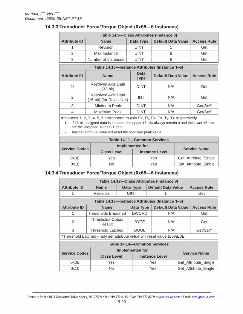
Manual, FT, Net FTDocument #9620-05-NET FT-13
Pinnacle Park • 1031 Goodworth Drive • Apex, NC 27539 • Tel: 919.772.0115 • Fax: 919.772.8259 • www.ati-ia.com • Email: [email protected] B-90
14.3.3 TransducerForce/TorqueObject(0x65—6Instances)Table 14.9—ClassAttributes(Instance0)
Attribute ID Name Data Type Default Data Value Access Rule1 Revision UINT 1 Get2 Max Instance UINT 6 Get3 Number of Instances UINT 6 Get
Table 14.10—InstanceAttributes(Instance1–6)
Attribute ID Name Data Type Default Data Value Access Rule
11 Resolved Axis Data (32-bit) DINT N/A Get
2 Resolved Axis Data (16-bit) (for DeviceNet) INT N/A Get
3 Minimum Peak DINT N/A Get/Set2
4 Maximum Peak DINT N/A Get/Set2
Instances 1, 2, 3, 4, 5, 6 correspond to axis Fx, Fy, Fz, Tx, Ty, Tz respectively.1. If 16-bit unsigned data is enabled, the upper 16 bits always remain 0 and the lower 16-bits
are the unsigned 16-bit F/T data.2. Anysetattributevaluewillresetthespecifiedpeakvalue.
Table 14.11—Common Services
Service CodesImplemented for
Service NameClassLevel InstanceLevel
0x0E Yes Yes Get_Attribute_Single0x10 No Yes Set_Attribute_Single
14.3.4 TransducerForce/TorqueObject(0x65—6Instances)Table 14.12—ClassAttributes(Instance0)
Attribute ID Name Data Type Default Data Value Access Rule1 Revision UINT 1 Get
Table 14.13—InstanceAttributes(Instance1–6)Attribute ID Name Data Type Default Data Value Access Rule
1 Thresholds Breached DWORD N/A Get
2 Thresholds Output Result BYTE N/A Get
3 Threshold Latched BOOL N/A Get/Set††Threshold Latched – any set attribute value will reset value to FALSE.
Table 14.14—Common Services
Service CodesImplemented for
Service NameClassLevel InstanceLevel
0x0E Yes Yes Get_Attribute_Single0x10 No Yes Set_Attribute_Single
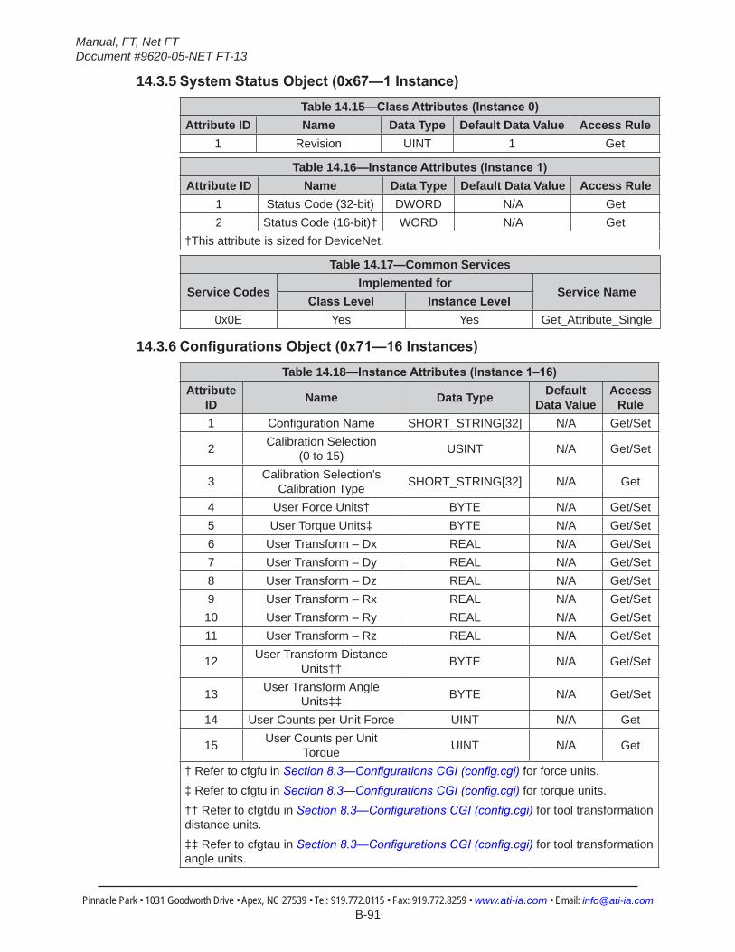
Manual, FT, Net FTDocument #9620-05-NET FT-13
Pinnacle Park • 1031 Goodworth Drive • Apex, NC 27539 • Tel: 919.772.0115 • Fax: 919.772.8259 • www.ati-ia.com • Email: [email protected] B-91
14.3.5 SystemStatusObject(0x67—1Instance)Table 14.15—ClassAttributes(Instance0)
Attribute ID Name Data Type Default Data Value Access Rule1 Revision UINT 1 Get
Table 14.16—InstanceAttributes(Instance1)Attribute ID Name Data Type Default Data Value Access Rule
1 Status Code (32-bit) DWORD N/A Get2 Status Code (16-bit)† WORD N/A Get
†This attribute is sized for DeviceNet.
Table 14.17—Common Services
Service CodesImplemented for
Service NameClassLevel InstanceLevel
0x0E Yes Yes Get_Attribute_Single
14.3.6 ConfigurationsObject(0x71—16Instances)Table 14.18—InstanceAttributes(Instance1–16)
Attribute ID Name Data Type Default
Data ValueAccess
Rule1 ConfigurationName SHORT_STRING[32] N/A Get/Set
2 Calibration Selection (0 to 15) USINT N/A Get/Set
3 Calibration Selection’s Calibration Type SHORT_STRING[32] N/A Get
4 User Force Units† BYTE N/A Get/Set5 User Torque Units‡ BYTE N/A Get/Set6 User Transform – Dx REAL N/A Get/Set7 User Transform – Dy REAL N/A Get/Set8 User Transform – Dz REAL N/A Get/Set9 User Transform – Rx REAL N/A Get/Set10 User Transform – Ry REAL N/A Get/Set11 User Transform – Rz REAL N/A Get/Set
12 User Transform Distance Units†† BYTE N/A Get/Set
13 User Transform Angle Units‡‡ BYTE N/A Get/Set
14 User Counts per Unit Force UINT N/A Get
15 User Counts per Unit Torque UINT N/A Get
† Refer to cfgfu in Section 8.3—Configurations CGI (config.cgi) for force units.‡ Refer to cfgtu in Section 8.3—Configurations CGI (config.cgi) for torque units.†† Refer to cfgtdu in Section 8.3—Configurations CGI (config.cgi) for tool transformation distance units.‡‡ Refer to cfgtau in Section 8.3—Configurations CGI (config.cgi) for tool transformation angle units.
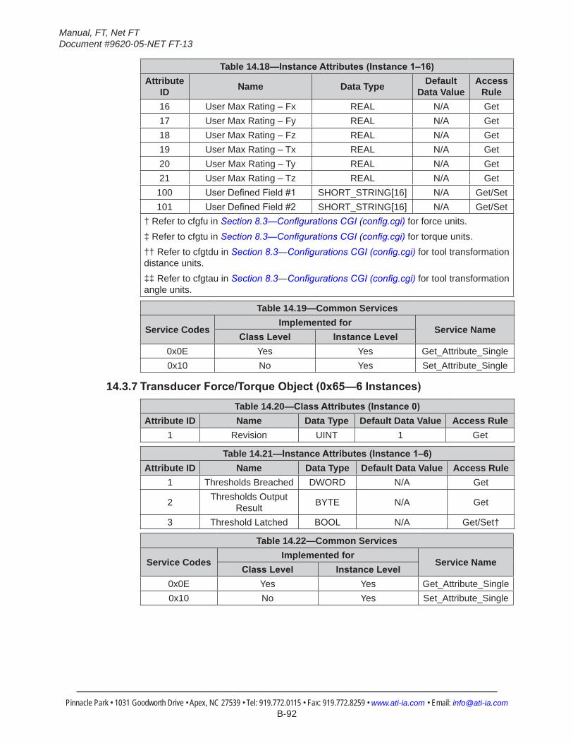
Manual, FT, Net FTDocument #9620-05-NET FT-13
Pinnacle Park • 1031 Goodworth Drive • Apex, NC 27539 • Tel: 919.772.0115 • Fax: 919.772.8259 • www.ati-ia.com • Email: [email protected] B-92
Table 14.18—InstanceAttributes(Instance1–16)Attribute
ID Name Data Type Default Data Value
Access Rule
16 User Max Rating – Fx REAL N/A Get17 User Max Rating – Fy REAL N/A Get18 User Max Rating – Fz REAL N/A Get19 User Max Rating – Tx REAL N/A Get20 User Max Rating – Ty REAL N/A Get21 User Max Rating – Tz REAL N/A Get100 UserDefinedField#1 SHORT_STRING[16] N/A Get/Set101 UserDefinedField#2 SHORT_STRING[16] N/A Get/Set
† Refer to cfgfu in Section 8.3—Configurations CGI (config.cgi) for force units.‡ Refer to cfgtu in Section 8.3—Configurations CGI (config.cgi) for torque units.†† Refer to cfgtdu in Section 8.3—Configurations CGI (config.cgi) for tool transformation distance units.‡‡ Refer to cfgtau in Section 8.3—Configurations CGI (config.cgi) for tool transformation angle units.
Table 14.19—Common Services
Service CodesImplemented for
Service NameClassLevel InstanceLevel
0x0E Yes Yes Get_Attribute_Single0x10 No Yes Set_Attribute_Single
14.3.7 TransducerForce/TorqueObject(0x65—6Instances)Table 14.20—ClassAttributes(Instance0)
Attribute ID Name Data Type Default Data Value Access Rule1 Revision UINT 1 Get
Table 14.21—InstanceAttributes(Instance1–6)Attribute ID Name Data Type Default Data Value Access Rule
1 Thresholds Breached DWORD N/A Get
2 Thresholds Output Result BYTE N/A Get
3 Threshold Latched BOOL N/A Get/Set†
Table 14.22—Common Services
Service CodesImplemented for
Service NameClassLevel InstanceLevel
0x0E Yes Yes Get_Attribute_Single0x10 No Yes Set_Attribute_Single
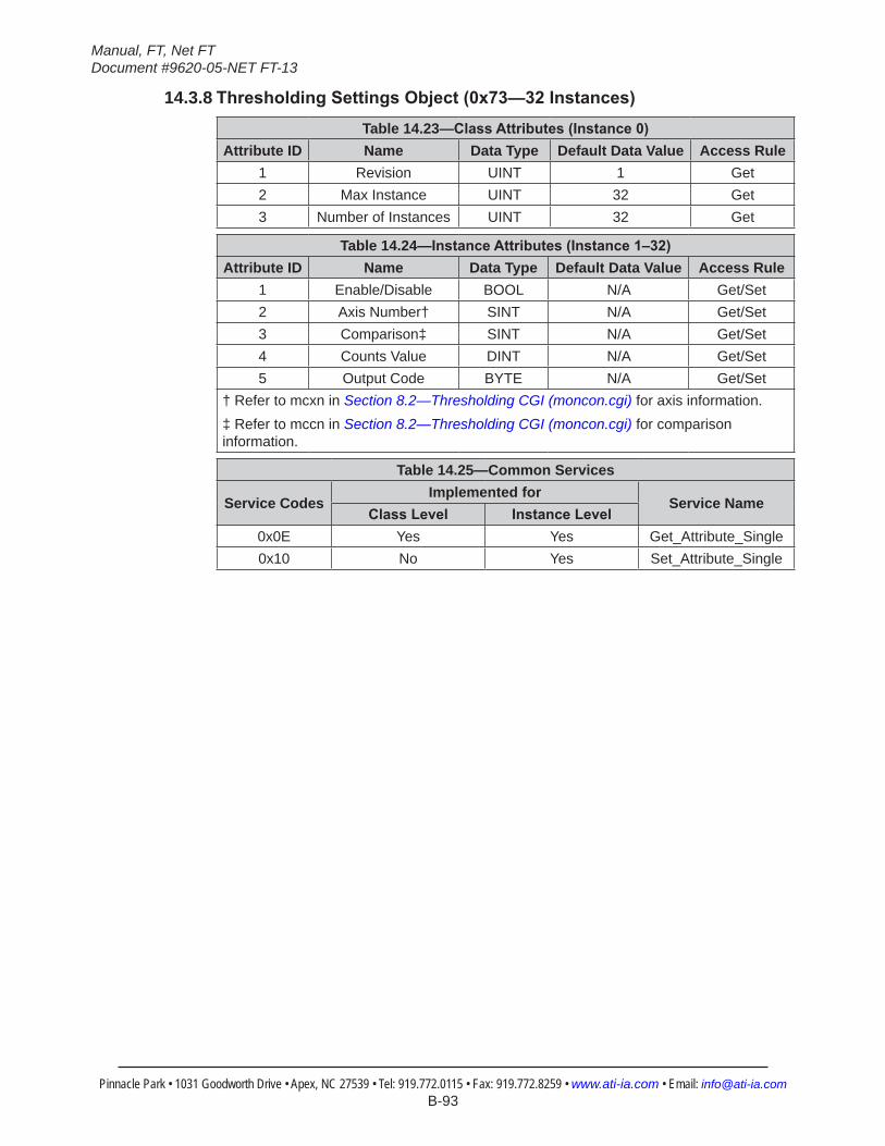
Manual, FT, Net FTDocument #9620-05-NET FT-13
Pinnacle Park • 1031 Goodworth Drive • Apex, NC 27539 • Tel: 919.772.0115 • Fax: 919.772.8259 • www.ati-ia.com • Email: [email protected] B-93
14.3.8 ThresholdingSettingsObject(0x73—32Instances)Table 14.23—ClassAttributes(Instance0)
Attribute ID Name Data Type Default Data Value Access Rule1 Revision UINT 1 Get2 Max Instance UINT 32 Get3 Number of Instances UINT 32 Get
Table 14.24—InstanceAttributes(Instance1–32)Attribute ID Name Data Type Default Data Value Access Rule
1 Enable/Disable BOOL N/A Get/Set2 Axis Number† SINT N/A Get/Set3 Comparison‡ SINT N/A Get/Set4 Counts Value DINT N/A Get/Set5 Output Code BYTE N/A Get/Set
† Refer to mcxn in Section 8.2—Thresholding CGI (moncon.cgi) for axis information.‡ Refer to mccn in Section 8.2—Thresholding CGI (moncon.cgi) for comparison information.
Table 14.25—Common Services
Service CodesImplemented for
Service NameClassLevel InstanceLevel
0x0E Yes Yes Get_Attribute_Single0x10 No Yes Set_Attribute_Single
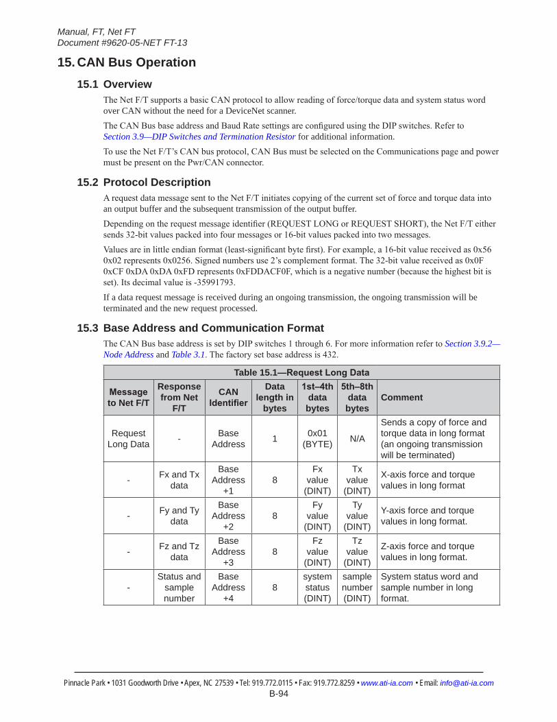
Manual, FT, Net FTDocument #9620-05-NET FT-13
Pinnacle Park • 1031 Goodworth Drive • Apex, NC 27539 • Tel: 919.772.0115 • Fax: 919.772.8259 • www.ati-ia.com • Email: [email protected] B-94
15. CAN Bus Operation15.1 Overview
The Net F/T supports a basic CAN protocol to allow reading of force/torque data and system status word over CAN without the need for a DeviceNet scanner.The CAN Bus base address and Baud Rate settings are configured using the DIP switches. Refer to Section 3.9—DIP Switches and Termination Resistor for additional information.To use the Net F/T’s CAN bus protocol, CAN Bus must be selected on the Communications page and power must be present on the Pwr/CAN connector.
15.2 Protocol DescriptionA request data message sent to the Net F/T initiates copying of the current set of force and torque data into an output buffer and the subsequent transmission of the output buffer.Depending on the request message identifier (REQUEST LONG or REQUEST SHORT), the Net F/T either sends 32-bit values packed into four messages or 16-bit values packed into two messages.Values are in little endian format (least-significant byte first). For example, a 16-bit value received as 0x56 0x02 represents 0x0256. Signed numbers use 2’s complement format. The 32-bit value received as 0x0F 0xCF 0xDA 0xDA 0xFD represents 0xFDDACF0F, which is a negative number (because the highest bit is set). Its decimal value is -35991793.If a data request message is received during an ongoing transmission, the ongoing transmission will be terminated and the new request processed.
15.3 Base Address and Communication FormatThe CAN Bus base address is set by DIP switches 1 through 6. For more information refer to Section 3.9.2—Node Address and Table 3.1. The factory set base address is 432.
Table 15.1—RequestLongData
Messageto Net F/T
Response from Net
F/T
CAN Identifier
Data lengthin
bytes
1st–4thdata bytes
5th–8thdata bytes
Comment
Request Long Data - Base
Address 1 0x01 (BYTE) N/A
Sends a copy of force and torque data in long format (an ongoing transmission will be terminated)
- Fx and Tx data
Base Address
+18
Fx value
(DINT)
Tx value
(DINT)
X-axis force and torque values in long format
- Fy and Ty data
Base Address
+28
Fy value
(DINT)
Ty value
(DINT)
Y-axis force and torque values in long format.
- Fz and Tz data
Base Address
+38
Fz value
(DINT)
Tz value
(DINT)
Z-axis force and torque values in long format.
-Status and
sample number
Base Address
+48
system status (DINT)
sample number (DINT)
System status word and sample number in long format.
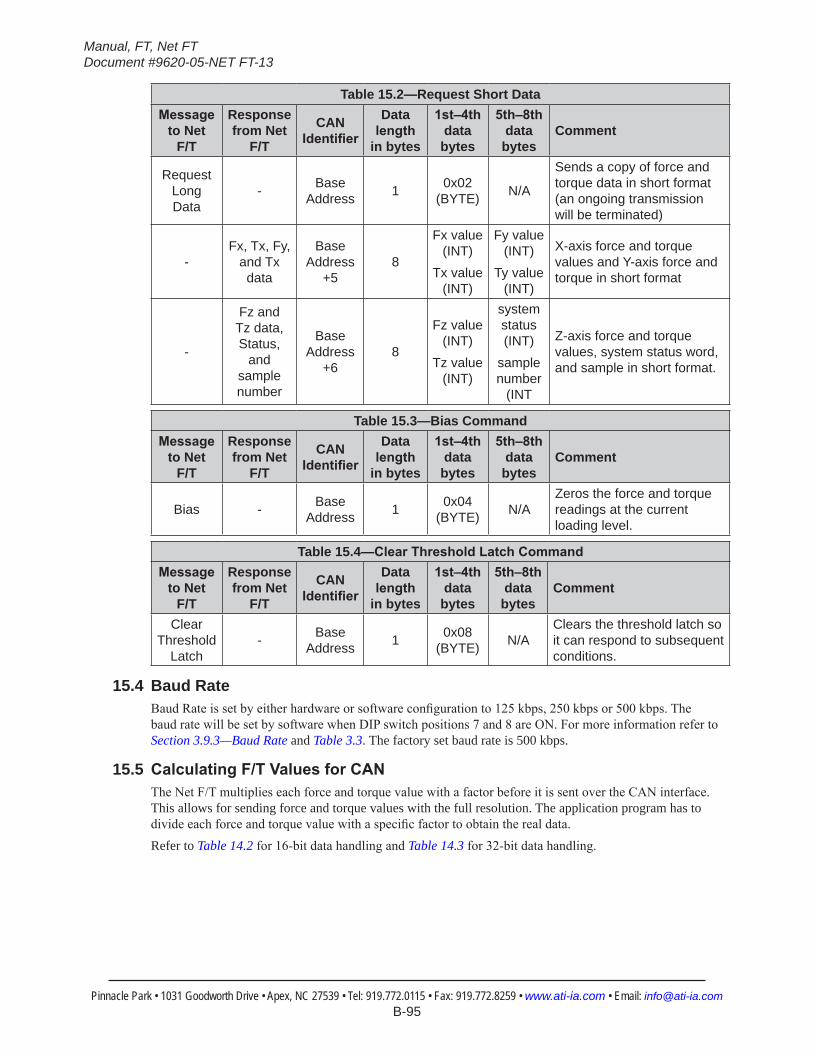
Manual, FT, Net FTDocument #9620-05-NET FT-13
Pinnacle Park • 1031 Goodworth Drive • Apex, NC 27539 • Tel: 919.772.0115 • Fax: 919.772.8259 • www.ati-ia.com • Email: [email protected] B-95
Table 15.2—Request Short DataMessage
to Net F/T
Response from Net
F/T
CAN Identifier
Data length
in bytes
1st–4thdata bytes
5th–8thdata bytes
Comment
Request Long Data
- Base Address 1 0x02
(BYTE) N/A
Sends a copy of force and torque data in short format (an ongoing transmission will be terminated)
-Fx, Tx, Fy,
and Tx data
Base Address
+58
Fx value (INT)
Tx value (INT)
Fy value (INT)
Ty value (INT)
X-axis force and torque values and Y-axis force and torque in short format
-
Fz and Tz data, Status,
and sample number
Base Address
+68
Fz value (INT)
Tz value (INT)
system status (INT)
sample number
(INT
Z-axis force and torque values, system status word, and sample in short format.
Table 15.3—Bias CommandMessage
to Net F/T
Response from Net
F/T
CAN Identifier
Data length
in bytes
1st–4thdata bytes
5th–8thdata bytes
Comment
Bias - Base Address 1 0x04
(BYTE) N/AZeros the force and torque readings at the current loading level.
Table 15.4—ClearThresholdLatchCommandMessage
to Net F/T
Response from Net
F/T
CAN Identifier
Data length
in bytes
1st–4thdata bytes
5th–8thdata bytes
Comment
Clear Threshold
Latch- Base
Address 1 0x08 (BYTE) N/A
Clears the threshold latch so it can respond to subsequent conditions.
15.4 Baud RateBaud Rate is set by either hardware or software configuration to 125 kbps, 250 kbps or 500 kbps. The baud rate will be set by software when DIP switch positions 7 and 8 are ON. For more information refer to Section 3.9.3—Baud Rate and Table 3.3. The factory set baud rate is 500 kbps.
15.5 CalculatingF/TValuesforCANThe Net F/T multiplies each force and torque value with a factor before it is sent over the CAN interface. This allows for sending force and torque values with the full resolution. The application program has to divide each force and torque value with a specific factor to obtain the real data.Refer to Table 14.2 for 16-bit data handling and Table 14.3 for 32-bit data handling.
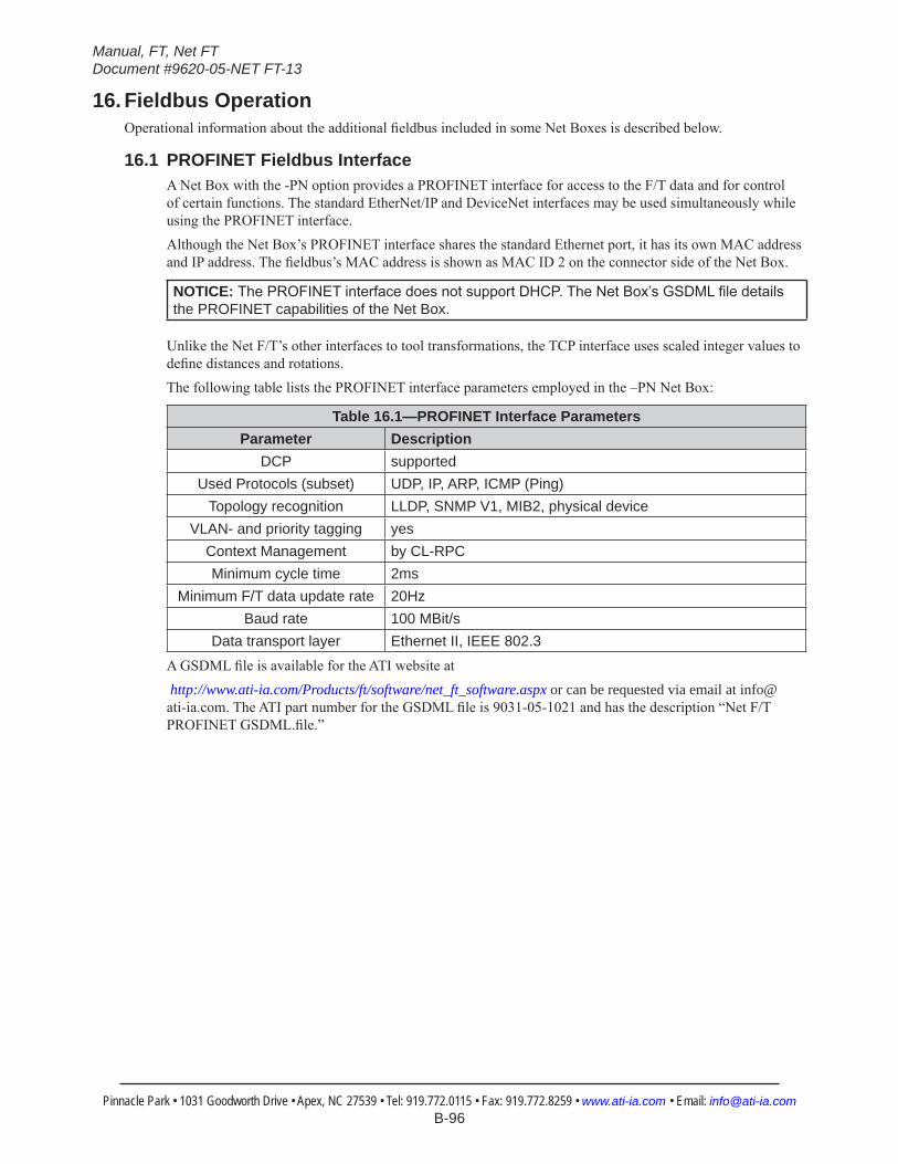
Manual, FT, Net FTDocument #9620-05-NET FT-13
Pinnacle Park • 1031 Goodworth Drive • Apex, NC 27539 • Tel: 919.772.0115 • Fax: 919.772.8259 • www.ati-ia.com • Email: [email protected] B-96
16. Fieldbus OperationOperational information about the additional fieldbus included in some Net Boxes is described below.
16.1 PROFINET Fieldbus InterfaceA Net Box with the -PN option provides a PROFINET interface for access to the F/T data and for control of certain functions. The standard EtherNet/IP and DeviceNet interfaces may be used simultaneously while using the PROFINET interface.Although the Net Box’s PROFINET interface shares the standard Ethernet port, it has its own MAC address and IP address. The fieldbus’s MAC address is shown as MAC ID 2 on the connector side of the Net Box.
NOTICE: ThePROFINETinterfacedoesnotsupportDHCP.TheNetBox’sGSDMLfiledetailsthe PROFINET capabilities of the Net Box.
Unlike the Net F/T’s other interfaces to tool transformations, the TCP interface uses scaled integer values to define distances and rotations.The following table lists the PROFINET interface parameters employed in the –PN Net Box:
Table 16.1—PROFINET Interface ParametersParameter Description
DCP supportedUsed Protocols (subset) UDP, IP, ARP, ICMP (Ping)
Topology recognition LLDP, SNMP V1, MIB2, physical deviceVLAN- and priority tagging yes
Context Management by CL-RPCMinimum cycle time 2ms
Minimum F/T data update rate 20HzBaud rate 100 MBit/s
Data transport layer Ethernet II, IEEE 802.3A GSDML file is available for the ATI website at http://www.ati-ia.com/Products/ft/software/net_ft_software.aspx or can be requested via email at [email protected]. The ATI part number for the GSDML file is 9031-05-1021 and has the description “Net F/T PROFINET GSDML.file.”
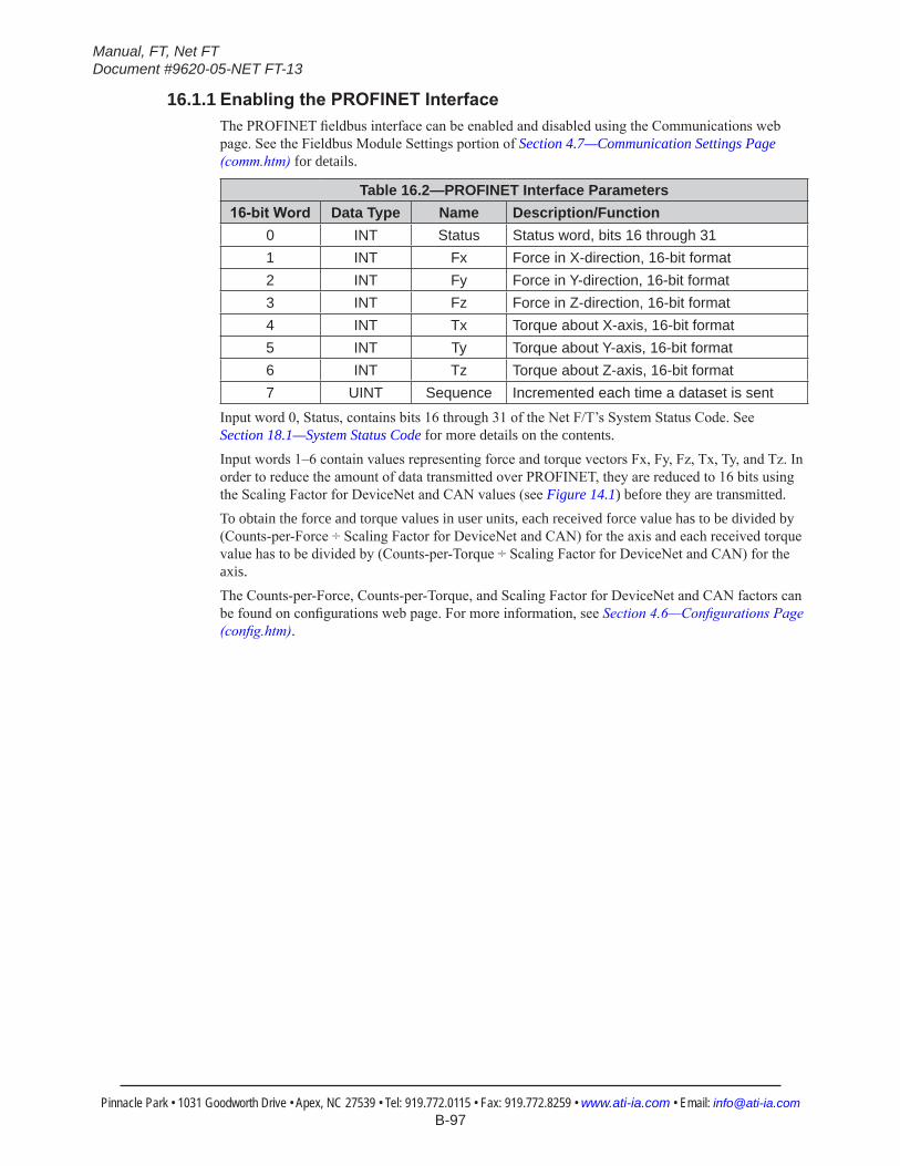
Manual, FT, Net FTDocument #9620-05-NET FT-13
Pinnacle Park • 1031 Goodworth Drive • Apex, NC 27539 • Tel: 919.772.0115 • Fax: 919.772.8259 • www.ati-ia.com • Email: [email protected] B-97
16.1.1 EnablingthePROFINETInterfaceThe PROFINET fieldbus interface can be enabled and disabled using the Communications web page. See the Fieldbus Module Settings portion of Section 4.7—Communication Settings Page (comm.htm) for details.
Table 16.2—PROFINET Interface Parameters16-bitWord Data Type Name Description/Function
0 INT Status Status word, bits 16 through 311 INT Fx Force in X-direction, 16-bit format2 INT Fy Force in Y-direction, 16-bit format3 INT Fz Force in Z-direction, 16-bit format4 INT Tx Torque about X-axis, 16-bit format5 INT Ty Torque about Y-axis, 16-bit format6 INT Tz Torque about Z-axis, 16-bit format7 UINT Sequence Incremented each time a dataset is sent
Input word 0, Status, contains bits 16 through 31 of the Net F/T’s System Status Code. See Section 18.1—System Status Code for more details on the contents.Input words 1–6 contain values representing force and torque vectors Fx, Fy, Fz, Tx, Ty, and Tz. In order to reduce the amount of data transmitted over PROFINET, they are reduced to 16 bits using the Scaling Factor for DeviceNet and CAN values (see Figure 14.1) before they are transmitted.To obtain the force and torque values in user units, each received force value has to be divided by (Counts-per-Force ÷ Scaling Factor for DeviceNet and CAN) for the axis and each received torque value has to be divided by (Counts-per-Torque ÷ Scaling Factor for DeviceNet and CAN) for the axis.The Counts-per-Force, Counts-per-Torque, and Scaling Factor for DeviceNet and CAN factors can be found on configurations web page. For more information, see Section 4.6—Configurations Page (config.htm).
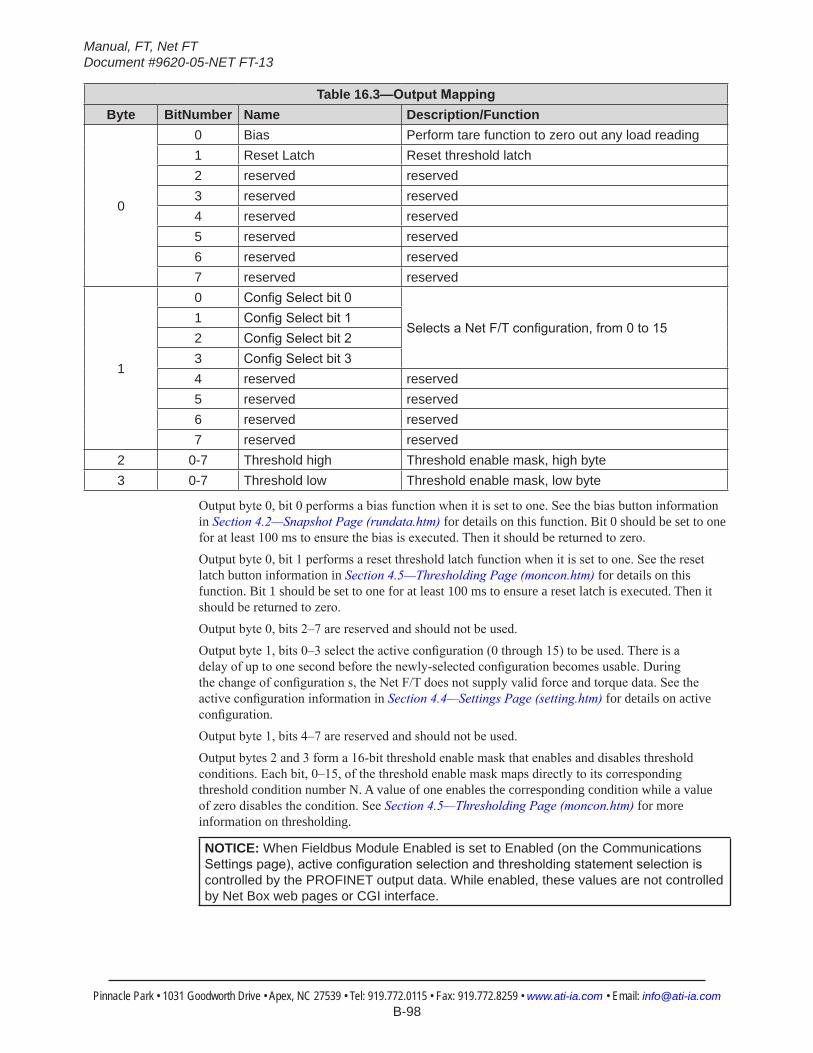
Manual, FT, Net FTDocument #9620-05-NET FT-13
Pinnacle Park • 1031 Goodworth Drive • Apex, NC 27539 • Tel: 919.772.0115 • Fax: 919.772.8259 • www.ati-ia.com • Email: [email protected] B-98
Table 16.3—OutputMappingByte BitNumber Name Description/Function
0
0 Bias Perform tare function to zero out any load reading1 Reset Latch Reset threshold latch2 reserved reserved3 reserved reserved4 reserved reserved5 reserved reserved6 reserved reserved7 reserved reserved
1
0 ConfigSelectbit0
SelectsaNetF/Tconfiguration,from0to151 ConfigSelectbit12 ConfigSelectbit23 ConfigSelectbit34 reserved reserved5 reserved reserved6 reserved reserved7 reserved reserved
2 0-7 Threshold high Threshold enable mask, high byte3 0-7 Threshold low Threshold enable mask, low byte
Output byte 0, bit 0 performs a bias function when it is set to one. See the bias button information in Section 4.2—Snapshot Page (rundata.htm) for details on this function. Bit 0 should be set to one for at least 100 ms to ensure the bias is executed. Then it should be returned to zero.Output byte 0, bit 1 performs a reset threshold latch function when it is set to one. See the reset latch button information in Section 4.5—Thresholding Page (moncon.htm) for details on this function. Bit 1 should be set to one for at least 100 ms to ensure a reset latch is executed. Then it should be returned to zero.Output byte 0, bits 2–7 are reserved and should not be used.Output byte 1, bits 0–3 select the active configuration (0 through 15) to be used. There is a delay of up to one second before the newly-selected configuration becomes usable. During the change of configuration s, the Net F/T does not supply valid force and torque data. See the active configuration information in Section 4.4—Settings Page (setting.htm) for details on active configuration.Output byte 1, bits 4–7 are reserved and should not be used.Output bytes 2 and 3 form a 16-bit threshold enable mask that enables and disables threshold conditions. Each bit, 0–15, of the threshold enable mask maps directly to its corresponding threshold condition number N. A value of one enables the corresponding condition while a value of zero disables the condition. See Section 4.5—Thresholding Page (moncon.htm) for more information on thresholding.
NOTICE: When Fieldbus Module Enabled is set to Enabled (on the Communications Settingspage),activeconfigurationselectionandthresholdingstatementselectioniscontrolled by the PROFINET output data. While enabled, these values are not controlled by Net Box web pages or CGI interface.
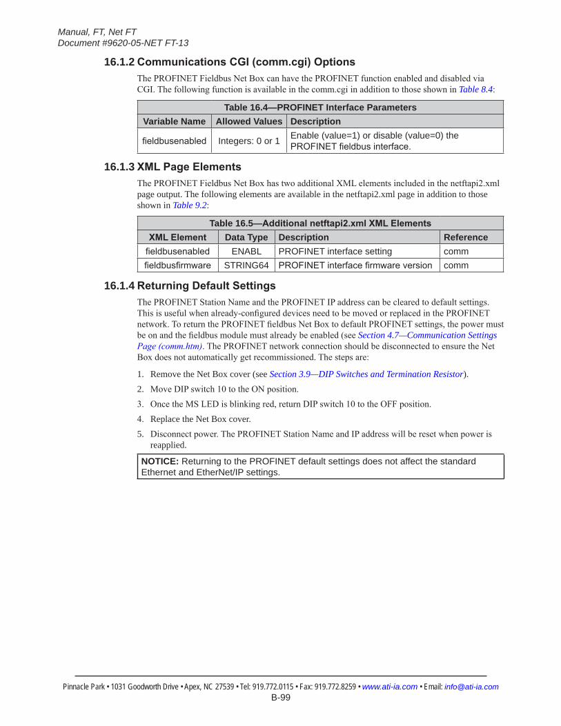
Manual, FT, Net FTDocument #9620-05-NET FT-13
Pinnacle Park • 1031 Goodworth Drive • Apex, NC 27539 • Tel: 919.772.0115 • Fax: 919.772.8259 • www.ati-ia.com • Email: [email protected] B-99
16.1.2 CommunicationsCGI(comm.cgi)OptionsThe PROFINET Fieldbus Net Box can have the PROFINET function enabled and disabled via CGI. The following function is available in the comm.cgi in addition to those shown in Table 8.4:
Table 16.4—PROFINET Interface ParametersVariable Name Allowed Values Description
fieldbusenabled Integers: 0 or 1 Enable (value=1) or disable (value=0) the PROFINETfieldbusinterface.
16.1.3 XMLPageElementsThe PROFINET Fieldbus Net Box has two additional XML elements included in the netftapi2.xml page output. The following elements are available in the netftapi2.xml page in addition to those shown in Table 9.2:
Table 16.5—Additionalnetftapi2.xmlXMLElementsXMLElement Data Type Description Referencefieldbusenabled ENABL PROFINET interface setting commfieldbusfirmware STRING64 PROFINETinterfacefirmwareversion comm
16.1.4 ReturningDefaultSettingsThe PROFINET Station Name and the PROFINET IP address can be cleared to default settings. This is useful when already-configured devices need to be moved or replaced in the PROFINET network. To return the PROFINET fieldbus Net Box to default PROFINET settings, the power must be on and the fieldbus module must already be enabled (see Section 4.7—Communication Settings Page (comm.htm). The PROFINET network connection should be disconnected to ensure the Net Box does not automatically get recommissioned. The steps are:
1. Remove the Net Box cover (see Section 3.9—DIP Switches and Termination Resistor).2. Move DIP switch 10 to the ON position.3. Once the MS LED is blinking red, return DIP switch 10 to the OFF position.4. Replace the Net Box cover.5. Disconnect power. The PROFINET Station Name and IP address will be reset when power is
reapplied.
NOTICE: Returning to the PROFINET default settings does not affect the standard Ethernet and EtherNet/IP settings.
Manual, FT, Net FTDocument #9620-05-NET FT-13
Pinnacle Park • 1031 Goodworth Drive • Apex, NC 27539 • Tel: 919.772.0115 • Fax: 919.772.8259 • www.ati-ia.com • Email: [email protected] B-100
16.1.5 ReplacingandInstalledPROFINETFieldbusNetBoxReplacing an installed PROFINET Fieldbus Net Box can easily be done if the Topology of the PROFINET network was properly defined with the PROFINET engineering tool and the PROFINET controller supports automatic device replacement.
16.1.5.1 ReplacingandInstalledPROFINETFieldbusNetBox1. Remove the power and network connections of the PROFINET Fieldbus Net Box
that is to be replaced. Mechanically unmount the Net Box if necessary.
2. Mount the replacement PROFINET Fieldbus Net Box and connect the power and PROFINET network connections to it.
3. The new Net Box will automatically be assigned the name and IP address of the former Net Box.
4. After a few seconds, the NS/BF LED will turn solid green and the Net Box will be correctly operating on the network.
16.1.5.2 Replacement with Previously Commissioned Fieldbus Net Box1. Remove the power and network connections of the PROFINET Fieldbus Net Box
that is to be replaced. Mechanically unmount the Net Box if necessary.
2. Mount the replacement PROFINET Fieldbus Net Box and connect the power to it. Do not make the network connection.
3. Follow the steps in Section 16.1.4—Returning Default Settings to remove the previous commission.
4. Connect the PROFINET Fieldbus Net Box to the PROFINET network.
5. The new Net Box will automatically be assigned the name and IP address of the former Net Box.
6. After a few seconds, the NS/BF LED will turn solid green and the Net Box will be correctly operating on the network.
Manual, FT, Net FTDocument #9620-05-NET FT-13
Pinnacle Park • 1031 Goodworth Drive • Apex, NC 27539 • Tel: 919.772.0115 • Fax: 919.772.8259 • www.ati-ia.com • Email: [email protected] B-101
17. Advanced Topics17.1 ImprovingEthernetThroughput
In an optimum network setup, the Net F/T’s RDT data will arrive at the host computer with no loss of dataIf you observe lost data samples, you may do one or all of the following:
17.1.1 Direct Connection between Net F/T and HostTo achieve the best Ethernet performance (and avoiding the loss of data packages), we recommend connecting the Net Box directly to the host computer. If you need to use a switch, then try to use only one switch between sensor system and host. Avoid going through several switches or going through a hub.
17.1.2 ChoiceofOperatingSystemThe Windows operating system periodically performs housekeeping processes that can require a significant amount of processing power over a short amount of time. During these intervals, a loss of data can occur because Windows does not treat UDP data with a high enough priority. If a loss of data is not acceptable for your application, then the use of a real-time operating system is recommended.
17.1.3 IncreasingOperatingSystemPerformanceThe following items may also help you increase the performance of your computer system so it can best respond to the Net F/T’s fast data rates:Disable software firewall. One way to improve the Ethernet performance is not to have any software firewall activated. In some cases, this may require help from IT personnel.Disable file and printer sharing. The processes associated what file and printer sharing can slow down an operating system’s response to Ethernet data and may lead to lost data.Disable unnecessary network services. Unnecessary network services and protocols can slow down an operating system’s response to Ethernet data and may lead to lost data. For the best UDP performance, it may be necessary to turn off every network service except for TCP/IP.Use an Ethernet traffic snooper. An Ethernet traffic snooper can be invaluable in detecting that there are processes using up Ethernet bandwidth and potentially slowing down the response of your computer’s operating system. This is an advanced technique that your IT department may need to perform. The free software program Wireshark (www.wireshark.org) is commonly used for this type of investigation.Use a dedicated computer. A dedicated measurement computer isolated from the company network will not be burdened by the company network processes.Use the Net F/T’s multi-unit synchronization capability if there are multiple Net F/Ts on the same network. This will eliminate data collisions from Net F/Ts transmitting at the same time.
17.1.4 AvoidLoggingtheHosttoaCompanyNetworkBeing logged onto a network requires the periodic access to the Ethernet interface by processes other than your measurement application. This can lead to loss of UDP packages.
17.1.5 Use a Dedicated NetworkPlacing the Net F/T on a dedicated Ethernet network with no other devices on the network, other than the host computer, will remove data collisions and give the best network performance.
Manual, FT, Net FTDocument #9620-05-NET FT-13
Pinnacle Park • 1031 Goodworth Drive • Apex, NC 27539 • Tel: 919.772.0115 • Fax: 919.772.8259 • www.ati-ia.com • Email: [email protected] B-102
17.2 ReducingNoise
17.2.1 Mechanical VibrationIn many cases, perceived noise is actually a real fluctuation of force and/or torque, caused by vibrations in the tooling or the robot arm. The Net F/T system offers digital low-pass filters that can dampen frequencies above a certain threshold. If this is not sufficient, you may want to add a digital filter to the application software.
17.2.2 Electrical InterferenceCheck the Net F/T’s ground connections if you observe interference by motors or other noise-generating equipment.Consider using the Net F/T’s digital low pass filters if sufficient grounding is not possible or does not reduce the noise.Verify that you are using a Class 1 power supply, which has an earth ground connection.
17.3 DetectingFailures(Diagnostics)
17.3.1 DetectingSensitivityChangesSensitivity checking of the transducer can also be used to measure the transducer system’s health. This is done by applying known loads to the transducer and verifying the system output matches the known loads. For example, a transducer mounted to a robot arm may have an end-effector attached to it.If the end-effector has moving parts, they must be moved in a known position. Place the robot arm in an orientation that allows the gravity load from the end-effector to exert load on many transducer output axes.Record the output readings.Position the robot arm to apply another load, this time causing the outputs to move far from the earlier readings.Record the second set of output readings.Find the differences from the first and second set of readings and use it as your sensitivity value.Even if the values vary somewhat from sample set to sample set, they can be used to detect gross errors. Either the resolved outputs or the raw transducer voltages may be used (the same must be used for all steps of this process).
17.4 Scheduled Maintenance
17.4.1 Periodic InspectionFor most applications, there are no parts that need to be replaced during normal operation. With industrial-type applications that continuously or frequently move the system’s cabling, you should periodically check the cable jacket for signs of wear. These applications should implement the procedures discussed in Section 17.3—Detecting Failures (Diagnostics) to detect any failures.The transducer must be kept free of excessive dust, debris, or moisture. Applications with metallic debris (i.e., electrically-conductive) must protect the transducer from this debris. Transducers without specific factory-installed protection are to be considered unprotected. The internal structure of the transducers can become clogged with particles and will become uncalibrated or even damaged.
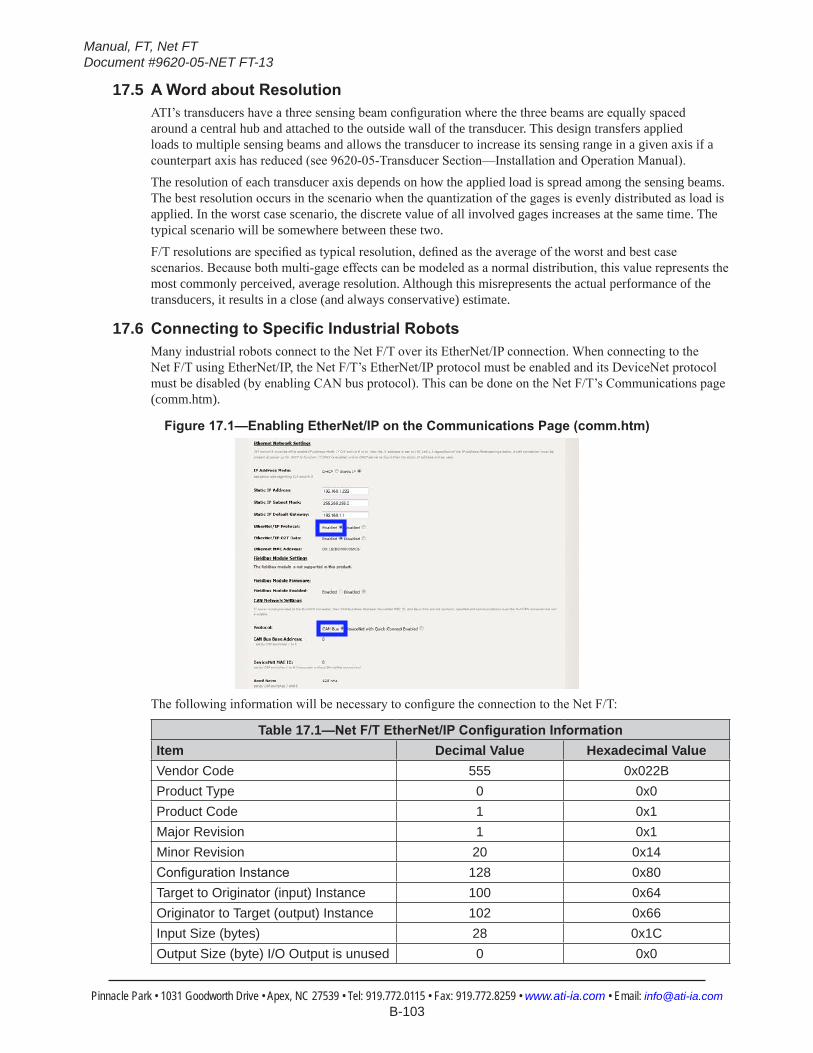
Manual, FT, Net FTDocument #9620-05-NET FT-13
Pinnacle Park • 1031 Goodworth Drive • Apex, NC 27539 • Tel: 919.772.0115 • Fax: 919.772.8259 • www.ati-ia.com • Email: [email protected] B-103
17.5 AWordaboutResolutionATI’s transducers have a three sensing beam configuration where the three beams are equally spaced around a central hub and attached to the outside wall of the transducer. This design transfers applied loads to multiple sensing beams and allows the transducer to increase its sensing range in a given axis if a counterpart axis has reduced (see 9620-05-Transducer Section—Installation and Operation Manual).The resolution of each transducer axis depends on how the applied load is spread among the sensing beams. The best resolution occurs in the scenario when the quantization of the gages is evenly distributed as load is applied. In the worst case scenario, the discrete value of all involved gages increases at the same time. The typical scenario will be somewhere between these two.F/T resolutions are specified as typical resolution, defined as the average of the worst and best case scenarios. Because both multi-gage effects can be modeled as a normal distribution, this value represents the most commonly perceived, average resolution. Although this misrepresents the actual performance of the transducers, it results in a close (and always conservative) estimate.
17.6 ConnectingtoSpecificIndustrialRobotsMany industrial robots connect to the Net F/T over its EtherNet/IP connection. When connecting to the Net F/T using EtherNet/IP, the Net F/T’s EtherNet/IP protocol must be enabled and its DeviceNet protocol must be disabled (by enabling CAN bus protocol). This can be done on the Net F/T’s Communications page (comm.htm).
Figure17.1—EnablingEtherNet/IPontheCommunicationsPage(comm.htm)
The following information will be necessary to configure the connection to the Net F/T:
Table 17.1—NetF/TEtherNet/IPConfigurationInformationItem Decimal Value Hexadecimal ValueVendor Code 555 0x022BProduct Type 0 0x0Product Code 1 0x1Major Revision 1 0x1Minor Revision 20 0x14ConfigurationInstance 128 0x80Target to Originator (input) Instance 100 0x64Originator to Target (output) Instance 102 0x66Input Size (bytes) 28 0x1COutput Size (byte) I/O Output is unused 0 0x0
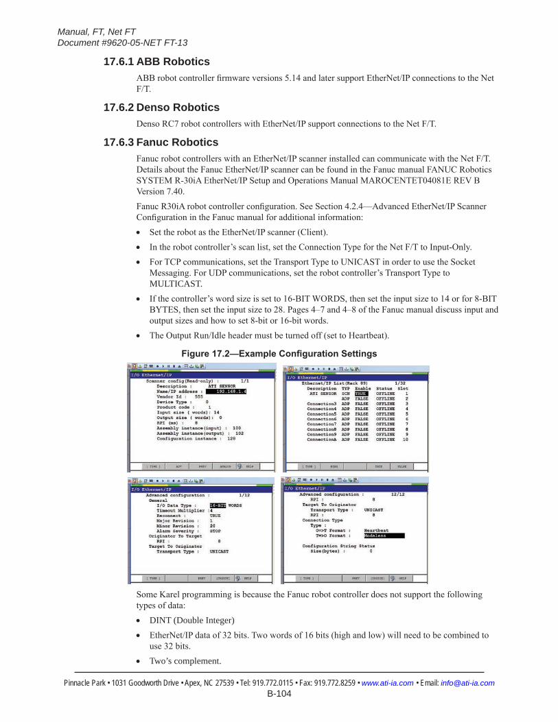
Manual, FT, Net FTDocument #9620-05-NET FT-13
Pinnacle Park • 1031 Goodworth Drive • Apex, NC 27539 • Tel: 919.772.0115 • Fax: 919.772.8259 • www.ati-ia.com • Email: [email protected] B-104
17.6.1 ABB RoboticsABB robot controller firmware versions 5.14 and later support EtherNet/IP connections to the Net F/T.
17.6.2 Denso RoboticsDenso RC7 robot controllers with EtherNet/IP support connections to the Net F/T.
17.6.3 Fanuc RoboticsFanuc robot controllers with an EtherNet/IP scanner installed can communicate with the Net F/T. Details about the Fanuc EtherNet/IP scanner can be found in the Fanuc manual FANUC Robotics SYSTEM R-30iA EtherNet/IP Setup and Operations Manual MAROCENTET04081E REV B Version 7.40.Fanuc R30iA robot controller configuration. See Section 4.2.4—Advanced EtherNet/IP Scanner Configuration in the Fanuc manual for additional information:• Set the robot as the EtherNet/IP scanner (Client).• In the robot controller’s scan list, set the Connection Type for the Net F/T to Input-Only.• For TCP communications, set the Transport Type to UNICAST in order to use the Socket
Messaging. For UDP communications, set the robot controller’s Transport Type to MULTICAST.
• If the controller’s word size is set to 16-BIT WORDS, then set the input size to 14 or for 8-BIT BYTES, then set the input size to 28. Pages 4–7 and 4–8 of the Fanuc manual discuss input and output sizes and how to set 8-bit or 16-bit words.
• The Output Run/Idle header must be turned off (set to Heartbeat).
Figure17.2—ExampleConfigurationSettings
Some Karel programming is because the Fanuc robot controller does not support the following types of data:• DINT (Double Integer)• EtherNet/IP data of 32 bits. Two words of 16 bits (high and low) will need to be combined to
use 32 bits.• Two’s complement.

Manual, FT, Net FTDocument #9620-05-NET FT-13
Pinnacle Park • 1031 Goodworth Drive • Apex, NC 27539 • Tel: 919.772.0115 • Fax: 919.772.8259 • www.ati-ia.com • Email: [email protected] B-105
17.6.4 Kuka RoboticsKuka robots with the KUKA.ForceTorqueControl package connect to the Net F/T and provide the robot with real-time force control.
17.6.5 Motoman RoboticsA Motoman robot controller with an EtherNet/IP add-on board is required for connections to the Net F/T.
Manual, FT, Net FTDocument #9620-05-NET FT-13
Pinnacle Park • 1031 Goodworth Drive • Apex, NC 27539 • Tel: 919.772.0115 • Fax: 919.772.8259 • www.ati-ia.com • Email: [email protected] B-106
18. TroubleshootingThis section includes answers to some issues that might arise when setting up and using the Net F/T system. The question or problem is listed followed by its probable answer or solution. They are categorized for easy reference.The information in this section should answer many questions that might arise in the field. Customer service is available to users who have problems or questions addressed in the manuals.
Note
Please read the manual before calling customer service. Before calling, have the following information available:
1. Serial number (e.g., FT01234)
2. Transducer model (e.g., Nano17, Gamma, Theta, etc.)
3. Calibration (e.g., US-15-50, SI-65-6, etc.)
4. Accurate and complete description of the question or problem
5. Computer and software information. Operating system, PC type, drivers, application software, and other relevant information about your configuration.
If possible, be near the F/T system when calling.
How to Reach Us
ATI Industrial Automation 1031 Goodworth Drive Apex, NC 27539 USA www.ati-ia.com
Application Engineering Tel: +1.919.772.0115, Option 2, Option 2 Fax: +1.919.772.8259 E-mail: [email protected]
18.1 System Status CodeThis section includes answers to some issues that might arise when setting up and using the Net F/T system. The question or problem is listed followed by its probable answer or solution. They are categorized for easy reference.The Net F/T performs many diagnostic checks during operation and reports results in a 32-bit system status code. Each F/T record includes this system status code. The bit patterns for all present error conditions are or’ed together to form the system status code. If any error condition is present then bit 31 of the system status code is set.Bit 16 is set if a threshold is latched. This bit does not indicate a system error.The system status code should be: 0x00000000 if no errors and no threshold statements are breached 0x80010000 if no errors and a threshold statement is breached.Any other code signals means there is a serious error. Table 16.1–System Status Code Bit Assignments describes possible errors and their bit assignments.
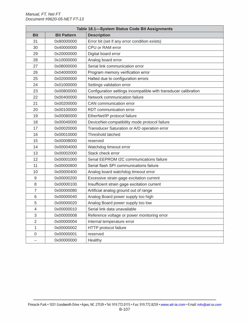
Manual, FT, Net FTDocument #9620-05-NET FT-13
Pinnacle Park • 1031 Goodworth Drive • Apex, NC 27539 • Tel: 919.772.0115 • Fax: 919.772.8259 • www.ati-ia.com • Email: [email protected] B-107
Table 18.1—SystemStatusCodeBitAssignmentsBit Bit Pattern Description31 0x80000000 Error bit (set if any error condition exists)30 0x40000000 CPU or RAM error29 0x20000000 Digital board error28 0x10000000 Analog board error27 0x08000000 Serial link communication error26 0x04000000 Programmemoryverificationerror25 0x02000000 Haltedduetoconfigurationerrors24 0x01000000 Settings validation error23 0x00800000 Configurationsettingsincompatiblewithtransducercalibration22 0x00400000 Network communication failure21 0x00200000 CAN communication error20 0x00100000 RDT communication error19 0x00080000 EtherNet/IP protocol failure18 0x00040000 DeviceNet-compatibility mode protocol failure17 0x00020000 Transducer Saturation or A/D operation error16 0x00010000 Threshold latched15 0x00008000 reserved14 0x00004000 Watchdog timeout error13 0x00002000 Stack check error12 0x00001000 Serial EEPROM I2C communications failure11 0x00000800 SerialflashSPIcommunicationsfailure10 0x00000400 Analog board watchdog timeout error9 0x00000200 Excessive strain gage excitation current8 0x00000100 Insufficientstraingageexcitationcurrent7 0x00000080 Artificialanaloggroundoutofrange6 0x00000040 Analog Board power supply too high5 0x00000020 Analog Board power supply too low4 0x00000010 Serial link data unavailable3 0x00000008 Reference voltage or power monitoring error2 0x00000004 Internal temperature error1 0x00000002 HTTP protocol failure0 0x00000001 reserved– 0x00000000 Healthy

Manual, FT, Net FTDocument #9620-05-NET FT-13
Pinnacle Park • 1031 Goodworth Drive • Apex, NC 27539 • Tel: 919.772.0115 • Fax: 919.772.8259 • www.ati-ia.com • Email: [email protected] B-108
18.2 StatusWordThe status word is a bitmap which contains information about the errors that can occur in various subsystems of the Digital F/T sensor.
Table 18.2—StatusWordBitAssignmentsBit Description0 Watchdog reset – the analog board was reset by the watchdog timer.1 Excitation voltage too high 2 Excitation voltage too low 3 Artificialanaloggroundoutofrange(above0.007V).4 Power supply too high ( > 25V).5 Power supply too low ( < 10 V).6 Not used.7 Error accessing stored settings in EEPROM – EEPROM hardware did not respond.8 Invalidconfigurationdata(baudrate).9 Strain gauge bridge supply current too high ( > 3V on current sense).10 Not used (was Strain gauge bridge supply current too low)11 Thermistor too high (> 100C (1.5V on thermistor) ).12 Thermistor too low. (< -40C (0.1V on thermistor ).13 Not used (was DAC reading out of range )14 Not used.15 Any error sets this bit.
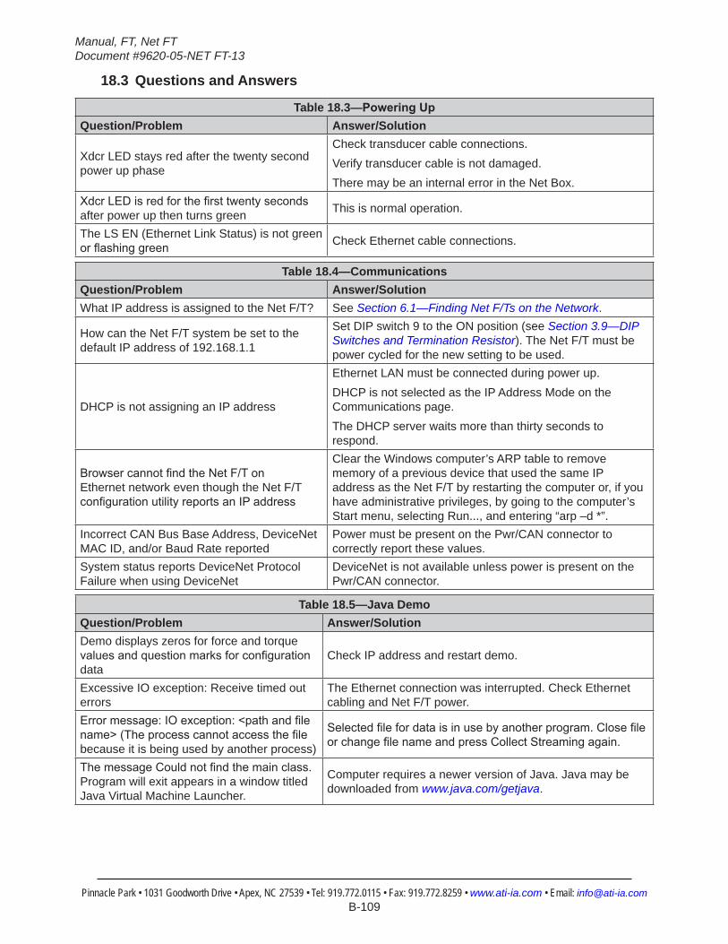
Manual, FT, Net FTDocument #9620-05-NET FT-13
Pinnacle Park • 1031 Goodworth Drive • Apex, NC 27539 • Tel: 919.772.0115 • Fax: 919.772.8259 • www.ati-ia.com • Email: [email protected] B-109
18.3 Questions and Answers
Table 18.3—PoweringUpQuestion/Problem Answer/Solution
Xdcr LED stays red after the twenty second power up phase
Check transducer cable connections.Verify transducer cable is not damaged.There may be an internal error in the Net Box.
XdcrLEDisredforthefirsttwentysecondsafter power up then turns green This is normal operation.
The LS EN (Ethernet Link Status) is not green orflashinggreen Check Ethernet cable connections.
Table 18.4—CommunicationsQuestion/Problem Answer/SolutionWhat IP address is assigned to the Net F/T? See Section 6.1—Finding Net F/Ts on the Network.
How can the Net F/T system be set to the default IP address of 192.168.1.1
Set DIP switch 9 to the ON position (see Section 3.9—DIP Switches and Termination Resistor). The Net F/T must be power cycled for the new setting to be used.
DHCP is not assigning an IP address
Ethernet LAN must be connected during power up.DHCP is not selected as the IP Address Mode on the Communications page.The DHCP server waits more than thirty seconds to respond.
BrowsercannotfindtheNetF/TonEthernet network even though the Net F/T configurationutilityreportsanIPaddress
Clear the Windows computer’s ARP table to remove memory of a previous device that used the same IP address as the Net F/T by restarting the computer or, if you have administrative privileges, by going to the computer’s Start menu, selecting Run..., and entering “arp –d *”.
Incorrect CAN Bus Base Address, DeviceNet MAC ID, and/or Baud Rate reported
Power must be present on the Pwr/CAN connector to correctly report these values.
System status reports DeviceNet Protocol Failure when using DeviceNet
DeviceNet is not available unless power is present on the Pwr/CAN connector.
Table 18.5—Java DemoQuestion/Problem Answer/SolutionDemo displays zeros for force and torque valuesandquestionmarksforconfigurationdata
Check IP address and restart demo.
Excessive IO exception: Receive timed out errors
The Ethernet connection was interrupted. Check Ethernet cabling and Net F/T power.
Errormessage:IOexception:<pathandfilename>(Theprocesscannotaccessthefilebecause it is being used by another process)
Selectedfilefordataisinusebyanotherprogram.ClosefileorchangefilenameandpressCollectStreamingagain.
ThemessageCouldnotfindthemainclass.Program will exit appears in a window titled Java Virtual Machine Launcher.
Computer requires a newer version of Java. Java may be downloaded from www.java.com/getjava.
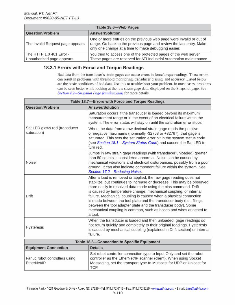
Manual, FT, Net FTDocument #9620-05-NET FT-13
Pinnacle Park • 1031 Goodworth Drive • Apex, NC 27539 • Tel: 919.772.0115 • Fax: 919.772.8259 • www.ati-ia.com • Email: [email protected] B-110
Table 18.6—WebPagesQuestion/Problem Answer/Solution
The Invalid Request page appearsOne or more entries on the previous web page were invalid or out of range. Go back to the previous page and review the last entry. Make only one change at a time to make debugging easier.
The HTTP 1.0 401 Error - Unauthorized page appears
You tried to access one of the protected pages of the web server. These pages are reserved for ATI Industrial Automation maintenance.
18.3.1 ErrorswithForceandTorqueReadingsBad data from the transducer’s strain gages can cause errors in force/torque readings. These errors can result in problems with threshold monitoring, transducer biasing, and accuracy. Listed below are the basic conditions of bad data. Use this to troubleshoot your problem. In most cases, problems can be seen better while looking at the raw strain gage data, displayed on the Snapshot page. See Section 4.2—Snapshot Page (rundata.htm) for more details.
Table 18.7—ErrorswithForceandTorqueReadingsQuestion/Problem Answer/Solution
Sat LED glows red (transducer saturation)
Saturation occurs if the transducer is loaded beyond its maximum measurement range or in the event of an electrical failure within the system. The error status will stay on until the saturation error stops.When the data from a raw decimal strain gage reads the positive or negative maximums (nominally -32768 or +32767), that gage is saturated. This sets the saturation error bit in the system status code (see Section 18.1—System Status Code) and causes the Sat LED to turn red.
Noise
Jumps in raw strain gage readings (with transducer unloaded) greater than 80 counts is considered abnormal. Noise can be caused by mechanical vibrations and electrical disturbances, possibly from a poor ground. It can also indicate component failure within the system. See Section 17.2—Reducing Noise.
Drift
After a load is removed or applied, the raw gage reading does not stabilize, but continues to increase or decrease. This may be observed more easily in resolved data mode using the bias command. Drift is caused by temperature change, mechanical coupling, or internal failure. Mechanical coupling is caused when a physical connection ismadebetweenthetoolplateandthetransducerbody(i.e.,filingsbetween the tool adapter plate and the transducer body). Some mechanical coupling is common, such as hoses and wires attached to a tool.
Hysteresis
When the transducer is loaded and then unloaded, gage readings do not return quickly and completely to their original readings. Hysteresis is caused by mechanical coupling (explained in Drift section) or internal failure.
Table 18.8—ConnectiontoSpecificEquipmentEquipment Connection Details
Fanuc robot controllers using EtherNet/IP
Set robot controller connection type to Input Only and set the robot controller as the EtherNet/IP scanner (client). When using Socket Messaging, set the transport type to Multicast for UDP or Unicast for TCP.
Manual, FT, Net FTDocument #9620-05-NET FT-13
Pinnacle Park • 1031 Goodworth Drive • Apex, NC 27539 • Tel: 919.772.0115 • Fax: 919.772.8259 • www.ati-ia.com • Email: [email protected] B-111
19. GeneralSpecifications19.1 Environmental
The standard F/T system is designed to be used in standard laboratory or light-manufacturing conditions. Transducers with an IP60 designation are able to withstand dusty environments. Transducers with an IP65 designation can be washed down with fresh water. Transducers with an IP68 designation can be submerged in up to 10 m of fresh water.The Net Box is rated to IP65.
19.1.1 StorageandOperatingTemperaturesThe Net F/T transducer and Net Box can be stored and used at varying temperatures.
Table 19.1—NetBoxStorageandOperatingTemperaturesStorageTemperature,°C OperatingTemperature,°C
-40 to +100 -20 to +70
NOTICE: These temperature ranges specify the storage and operation ranges in which the system can survive without damage. They do not take accuracy into account. See ATI Industrial Automation manual 9620-05-Transducer Section for transducer environmental information.
When mated with appropriate connectors, the 9105-Net Box can be used in wet environments. The 9105-NETB Net Box can only be used in humidity up to 95% RH, non-condensing.
19.2 TransducerDataFilteringFigure 19.1 shows the frequency response of the transducer’s data acquisition hardware and various filtering options. The graph does not include the effects of any mechanical filtering (which occurs in any spring and mass system).
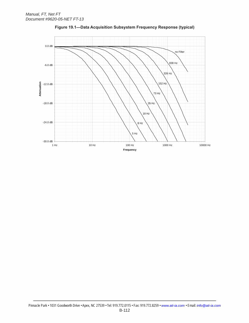
Manual, FT, Net FTDocument #9620-05-NET FT-13
Pinnacle Park • 1031 Goodworth Drive • Apex, NC 27539 • Tel: 919.772.0115 • Fax: 919.772.8259 • www.ati-ia.com • Email: [email protected] B-112
Figure19.1—DataAcquisitionSubsystemFrequencyResponse(typical)
-30.0 dB
-24.0 dB
-18.0 dB
-12.0 dB
-6.0 dB
0.0 dB
1 Hz 10 Hz 100 Hz 1000 Hz 10000 Hz
Frequency
Atte
nuat
ion
5 Hz
8 Hz
18 Hz
35 Hz
73 Hz
152 Hz
326 Hz
838 Hz
no Filter
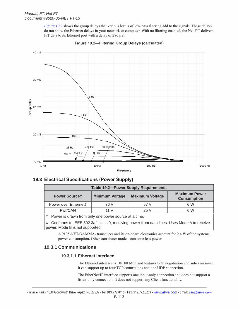
Manual, FT, Net FTDocument #9620-05-NET FT-13
Pinnacle Park • 1031 Goodworth Drive • Apex, NC 27539 • Tel: 919.772.0115 • Fax: 919.772.8259 • www.ati-ia.com • Email: [email protected] B-113
Figure 19.2 shows the group delays that various levels of low-pass filtering add to the signals. These delays do not show the Ethernet delays in your network or computer. With no filtering enabled, the Net F/T delivers F/T data to its Ethernet port with a delay of 286 µS.
Figure19.2—FilteringGroupDelays(calculated)
0 mS
10 mS
20 mS
30 mS
40 mS
1 Hz 10 Hz 100 Hz 1000 Hz
Frequency
Gro
up D
elay
838 Hz
no filtering326 Hz
152 Hz73 Hz
35 Hz
18 Hz
8 Hz
5 Hz
19.3 ElectricalSpecifications(PowerSupply)Table 19.2—Power Supply Requirements
Power Source† MinimumVoltage MaximumVoltage Maximum Power Consumption
Power over Ethernet‡ 36 V 57 V 6 WPwr/CAN 11 V 25 V 6 W
† Power is drawn from only one power source at a time.‡ Conforms to IEEE 802.3af, class 0, receiving power from data lines. Uses Mode A to receive power. Mode B is not supported.
A 9105-NET-GAMMA- transducer and its on-board electronics account for 2.4 W of the systems power consumption. Other transducer models consume less power.
19.3.1 Communications
19.3.1.1 Ethernet InterfaceThe Ethernet interface is 10/100 Mbit and features both negotiation and auto crossover. It can support up to four TCP connections and one UDP connection.
The EtherNet/IP interface supports one input-only connection and does not support a listen-only connection. It does not support any Client functionality.

Manual, FT, Net FTDocument #9620-05-NET FT-13
Pinnacle Park • 1031 Goodworth Drive • Apex, NC 27539 • Tel: 919.772.0115 • Fax: 919.772.8259 • www.ati-ia.com • Email: [email protected] B-114
19.3.1.2 CAN InterfaceThe CAN interface supports 125 kbps, 250 kbps, and 500 kbps (see Section 3.9.3—Baud Rate). A switchable termination resistor is available (see Section 3.9.1—Termination Resistor).
19.3.2 MatingConnectors
Table 19.3—MechanicalSpecificationsofMatingConnectorsConnector MatingType Recommended Torque Maximum Torque
Ethernet M12 D-Coded, 4-Pin, male 0.8 Nm to 1.0 Nm 3.0 Nm
Threshold Relay M8 3-Pin, female 0.5 Nm to 0.6 Nm 1.0 NmPwr/CAN M12 5-Pin, female 0.8 Nm to 1.0 Nm 3.0 Nm
NETB Transducer M12 5-Pin, male 0.8 Nm to 1.0 Nm 3.0 NmNETBA Transducer Circular, female 0.7 Nm
19.3.3 Standard Threshold RelayThe standard threshold relay contacts (NC, NO, or COM) are protected against overload by a resettable fuse. The relay will turn on within 6 ms.
Table 19.4—StandardThresholdRelaySpecificationsMaximumRating MaximumLoad
Current 50 mA 10 µAVoltage 42 VDC, 30 VAC 10 mVDC
19.3.4 Solid-State Threshold RelayThe optional solid state threshold relay contacts (SSR+ and SSR-) are protected against reverse voltage by a zener diode. The relay will turn on within 500 µs.
Table 19.5—Solid-StateRelaySpecificationsMaximumLoad
Current 35 mAVoltage 30 VDC
Figure19.3—Solid-StateRelayVoltageDropvs.Current Vssr vs. Issr
0V
1V
2V
3V
4V
5V
0mA 10mA 20mA 30mA 40mA
Issr (current)
Vssr
(vol
tage
dro
p)
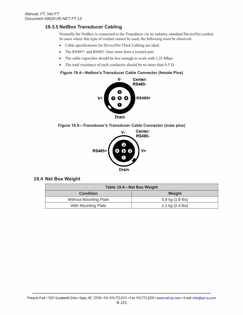
Manual, FT, Net FTDocument #9620-05-NET FT-13
Pinnacle Park • 1031 Goodworth Drive • Apex, NC 27539 • Tel: 919.772.0115 • Fax: 919.772.8259 • www.ati-ia.com • Email: [email protected] B-115
19.3.5 NetBoxTransducerCablingNormally the NetBox is connected to the Transducer via an industry-standard DeviceNet cordset. In cases where this type of cordset cannot be used, the following must be observed:• Cable specifications for DeviceNet Thick Cabling are ideal.• The RS485+ and RS485- lines must form a twisted pair.• The cable capacities should be low enough to work with 1.25 Mbps.• The total resistance of each conductor should be no more than 0.5 Ω
Figure19.4—Netbox’sTransducerCableConnector(femalePins)
Figure19.5—Transducer’sTransducerCableConnector(malepins)
19.4 NetBoxWeightTable 19.6—NetBoxWeight
Condition WeightWithout Mounting Plate 0.8 kg (1.8 lbs)
With Mounting Plate 1.1 kg (2.4 lbs)
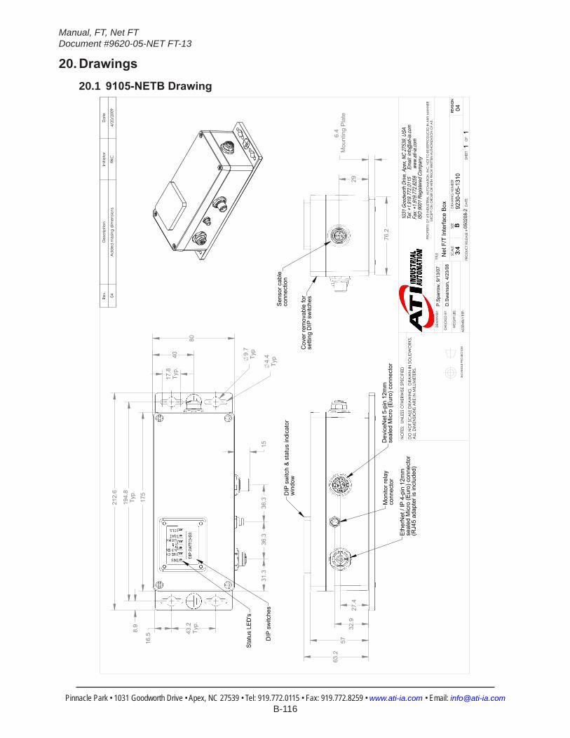
Manual, FT, Net FTDocument #9620-05-NET FT-13
Pinnacle Park • 1031 Goodworth Drive • Apex, NC 27539 • Tel: 919.772.0115 • Fax: 919.772.8259 • www.ati-ia.com • Email: [email protected] B-116
20. Drawings20.1 9105-NETBDrawing
175
15
212.
6
80
17.8
Typ.
43.2
Typ.
194.
8Ty
p.
16.5
8.9
9.7
Typ
4.4
Typ
31.3
36.3
36.3
40
DIP
sw
itche
s
Sta
tus
LED
's
5763
.2
32.9
27.4
DIP
sw
itch
& s
tatu
s in
dica
tor
win
dow
Eth
erN
et /
IP 4
-pin
12m
mse
aled
Mic
ro (E
uro)
con
nect
or(R
J45
adap
ter i
s in
clud
ed)
Mon
itor r
elay
conn
ecto
rD
evic
eNet
5-p
in 1
2mm
seal
ed M
icro
(Eur
o) c
onne
ctor
76.2
6.4
Mou
ntin
g P
late
29
Sen
sor c
able
conn
ectio
n
Cov
er re
mov
able
for
setti
ng D
IP s
witc
hesRe
v.D
escr
iptio
nIn
itiat
orD
ate
04A
dd
ed m
issin
g d
imen
sions
RKC
4/20
/200
9
B3:
41
1
REVI
SIO
N
NO
TES:
UN
LESS
OTH
ERW
ISE
SPEC
IFIE
D
DO
NO
T SC
ALE
DRA
WIN
G.
DRA
WN
IN S
OLID
WO
RKS.
ALL
DIM
ENSI
ON
S A
RE IN
MILL
IMET
ERS.
3rd
AN
GLE
PRO
JEC
TION
DRA
WN
BY:
CHE
CKE
D B
Y:
WEI
GHT
LBS
:
ASS
EMBL
Y RE
F:
P.Sp
arro
w, 9
/13/
07
D.S
wan
son,
4/2
3/08
TITLE SC
ALE
SIZE
DRA
WIN
G N
UMBE
R
PRO
DUC
T RE
LEA
SE #
SHEE
T
OF
9230
-05-
1310
B3:
41
1
0502
08-2
REVI
SIO
N
04
PRO
PERT
Y O
F A
TI IN
DUS
TRIA
L A
UTO
MA
TION
, IN
C. N
OT
TO B
E RE
PRO
DUC
ED IN
AN
Y M
AN
NER
EXC
EPT
ON
ORD
ER O
R W
ITH P
RIO
R W
RITT
EN A
UTHO
RIZA
TION
OF
ATI.
1031
Goo
dwor
th Dr
ive, A
pex,
NC 27
539,
USA
Tel: +
1.919
.772.0
115
Em
ail: in
fo@ati
-ia.co
mFa
x: +1
.919.7
72.82
59
www
.ati-ia
.com
ISO
9001
Reg
ister
ed C
ompa
ny
Net
F/T
Inte
rface
Box D
ATE
:
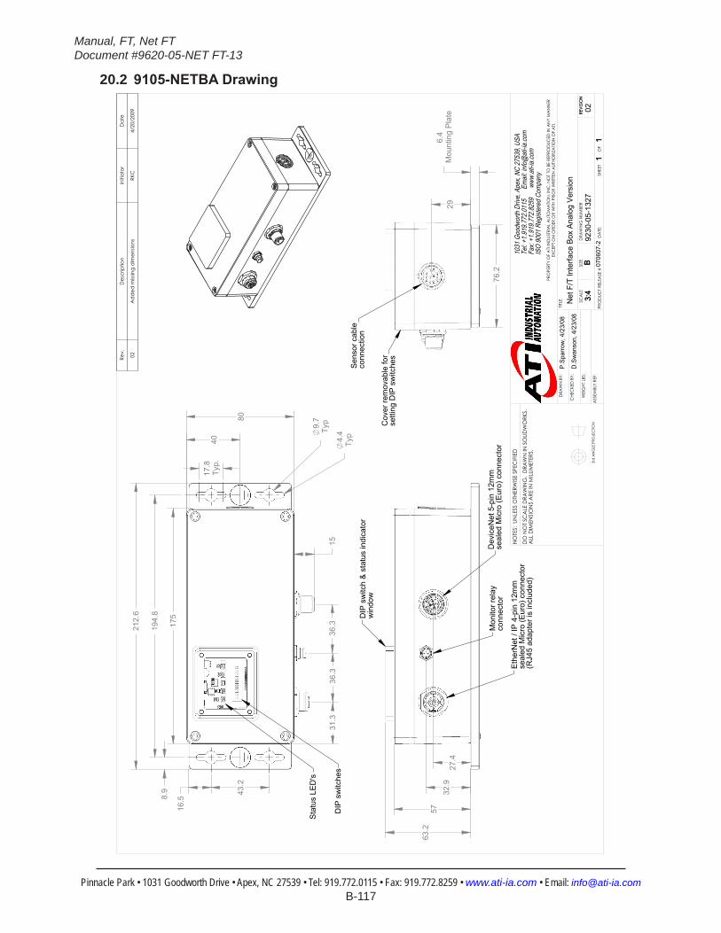
Manual, FT, Net FTDocument #9620-05-NET FT-13
Pinnacle Park • 1031 Goodworth Drive • Apex, NC 27539 • Tel: 919.772.0115 • Fax: 919.772.8259 • www.ati-ia.com • Email: [email protected] B-117
20.2 9105-NETBADrawing
16.5
43.2
17.8
Typ.
194.
8
80
175
212.
6
8.9
9.7
Typ
4.4
Typ
36.3
36.3
1531
.3
40
DIP
sw
itche
s
Sta
tus
LED
's
5763
.2
27.4
32.9
DIP
sw
itch
& s
tatu
s in
dica
tor
win
dow
Eth
erN
et /
IP 4
-pin
12m
mse
aled
Mic
ro (E
uro)
con
nect
or(R
J45
adap
ter i
s in
clud
ed)
Mon
itor r
elay
conn
ecto
rD
evic
eNet
5-p
in 1
2mm
seal
ed M
icro
(Eur
o) c
onne
ctor
76.2
6.4
Mou
ntin
g P
late
29
Sen
sor c
able
conn
ectio
n
Cov
er re
mov
able
for
setti
ng D
IP s
witc
hesRe
v.D
escr
iptio
nIn
itiat
orD
ate
02A
dd
ed m
issin
g d
imen
sions
RKC
4/20
/200
9
B3:
41
1
REVI
SIO
N
NO
TES:
UN
LESS
OTH
ERW
ISE
SPEC
IFIE
D
DO
NO
T SC
ALE
DRA
WIN
G.
DRA
WN
IN S
OLID
WO
RKS.
ALL
DIM
ENSI
ON
S A
RE IN
MILL
IMET
ERS.
3rd
AN
GLE
PRO
JEC
TION
DRA
WN
BY:
CHE
CKE
D B
Y:
WEI
GHT
LBS
:
ASS
EMBL
Y RE
F:
P.Sp
arro
w, 4
/23/
08
D.S
wan
son,
4/2
3/08
TITLE SC
ALE
SIZE
DRA
WIN
G N
UMBE
R
PRO
DUC
T RE
LEA
SE #
SHEE
T
OF
9230
-05-
1327
B3:
41
1
0706
07-2
REVI
SIO
N
02
PRO
PERT
Y O
F A
TI IN
DUS
TRIA
L A
UTO
MA
TION
, IN
C. N
OT
TO B
E RE
PRO
DUC
ED IN
AN
Y M
AN
NER
EXC
EPT
ON
ORD
ER O
R W
ITH P
RIO
R W
RITT
EN A
UTHO
RIZA
TION
OF
ATI.
1031
Goo
dwor
th Dr
ive, A
pex,
NC 27
539,
USA
Tel: +
1.919
.772.0
115
Em
ail: in
fo@ati
-ia.co
mFa
x: +1
.919.7
72.82
59
www
.ati-ia
.com
ISO
9001
Reg
ister
ed C
ompa
ny
Net
F/T
Inte
rface
Box
Ana
log
Vers
ion
DA
TE:

Manual, FT, Net FTDocument #9620-05-NET FT-13
Pinnacle Park • 1031 Goodworth Drive • Apex, NC 27539 • Tel: 919.772.0115 • Fax: 919.772.8259 • www.ati-ia.com • Email: [email protected] B-118
20.3 9105-NETB-PN2Drawing
3rd
AN
GLE
PRO
JEC
TION
77
71
7.6
Spa
cer P
late
6
.4 M
ount
ing
Pla
te
IP67
Rat
edS
elf-C
losi
ng C
ap
Pow
er
Con
nect
or
OU
T
Eth
erne
t C
onne
ctor
O
UT
Eth
erne
t C
onne
ctor
IN
Pow
er
Con
nect
or
IN
80
175
212
.6
194
.8
43.
2 7
6.2
117
.2
A
B
DIP
Sw
itche
s
Con
nect
or
Mou
ntin
gB
lock
Con
figur
atio
n C
onne
ctor
DIP
Sw
itch
& S
tatu
sIn
dica
tor w
indo
w
Mon
itor R
elay
C
onne
ctor
43.
1
Tran
sduc
er
Con
nect
orC
over
rem
ovab
le
for s
ettin
g D
IP
Sw
itche
s
4X
4.4
Thr
u
4X 1
7.8
Thru
4X
9.
7 Th
ru
DE
TAIL
A
SC
ALE
1.5
: 1
Sta
tus
LED
Det
ail B
SF
EN
1E
N2
BF
SA
Txd
cr
Not
es:
1. C
onne
ctor
pin
des
igna
tions
sho
wn
on S
heet
2.
Rev.
Des
crip
tion
Initi
ator
Dat
e
03A
dd
ed S
pace
r Pla
tes
LCS
9/13
/201
3
B1:
21
2RE
VISI
ON
NO
TES:
UN
LESS
OTH
ERW
ISE
SPEC
IFIE
D.
DO
NO
T SC
ALE
DRA
WIN
G.
ALL
DIM
ENSI
ON
S A
RE IN
M
ILLIM
ETER
S.
DRA
WN
BY:
CHE
CKE
D B
Y:
J. W
alse
r 10/
26/2
012
R. C
ham
bers
10/
26/1
2
TITLE SC
ALE
SIZE
DRA
WIN
G N
UMBE
R
PRO
JEC
T #
SHEE
T
O
F 92
30-0
5-14
3811
1103
-103
PRO
PERT
Y O
F A
TI IN
DUS
TRIA
L A
UTO
MA
TION
, IN
C. N
OT
TO B
E RE
PRO
DUC
ED IN
AN
Y M
AN
NER
EXC
EPT
ON
ORD
ER O
R W
ITH P
RIO
R W
RITT
EN A
UTHO
RIZA
TION
OF
ATI.
1031
Goo
dwor
th Dr
ive, A
pex,
NC 27
539,
USA
Tel: +
1.919
.772.0
115
Em
ail: in
fo@ati
-ia.co
mFa
x: +1
.919.7
72.82
59
www
.ati-ia
.com
ISO
9001
Reg
ister
ed C
ompa
ny
Net
Box
, Pro
finet
w/ A
IDA
Con
nect
ors
for
Larg
e Tr
ansd
ucer
s w
/ Int
erna
l Ele
ctro
nics
(9
105-
NET
B-PN
2)

Manual, FT, Net FTDocument #9620-05-NET FT-13
Pinnacle Park • 1031 Goodworth Drive • Apex, NC 27539 • Tel: 919.772.0115 • Fax: 919.772.8259 • www.ati-ia.com • Email: [email protected] B-119
3rd
AN
GLE
PRO
JEC
TION
Pow
er C
onne
ctor
IN /
OU
TP
heon
ix C
onta
ct 5
-Pin
Mal
eH
eade
r: 16
0956
5P
anel
Mou
ntin
g Fr
ame:
160
8087
Eth
erne
t Con
nect
or IN
/ O
UT
Pho
enix
Con
tact
RJ4
5S
ocke
t: 16
5309
0P
anel
Mou
ntin
g Fr
ame:
160
8029
Tran
sduc
er C
onne
ctor
Turc
k eu
rofa
st 5
-Pin
M12
Fem
ale
FKFD
LV 5
7
Mon
itor R
elay
Con
nect
orTu
rck
pico
fast
3-P
in M
8 M
ale
MFS
S 3
-0.2
Con
figur
atio
n C
onne
ctor
Har
ting
RJ4
5 TB
09
45 2
15 1
562
B1:
22
2RE
VISI
ON
NO
TES:
UN
LESS
OTH
ERW
ISE
SPEC
IFIE
D.
DO
NO
T SC
ALE
DRA
WIN
G.
ALL
DIM
ENSI
ON
S A
RE IN
M
ILLIM
ETER
S.
DRA
WN
BY:
CHE
CKE
D B
Y:
J. W
alse
r 10/
26/2
012
R. C
ham
bers
10/
26/1
2
TITLE SC
ALE
SIZE
DRA
WIN
G N
UMBE
R
PRO
JEC
T #
SHEE
T
O
F 92
30-0
5-14
3811
1103
-103
PRO
PERT
Y O
F A
TI IN
DUS
TRIA
L A
UTO
MA
TION
, IN
C. N
OT
TO B
E RE
PRO
DUC
ED IN
AN
Y M
AN
NER
EXC
EPT
ON
ORD
ER O
R W
ITH P
RIO
R W
RITT
EN A
UTHO
RIZA
TION
OF
ATI.
1031
Goo
dwor
th Dr
ive, A
pex,
NC 27
539,
USA
Tel: +
1.919
.772.0
115
Em
ail: in
fo@ati
-ia.co
mFa
x: +1
.919.7
72.82
59
www
.ati-ia
.com
ISO
9001
Reg
ister
ed C
ompa
ny
Net
Box
, Pro
finet
w/ A
IDA
Con
nect
ors
for
Larg
e Tr
ansd
ucer
s w
/ Int
erna
l Ele
ctro
nics
(9
105-
NET
B-PN
2)