net safety jb series junction box - emerson · 3.2.3 millennium st1 toxic sensor series ... the net...
TRANSCRIPT

Reference Manual MAN-0081, Rev 5
June 2016
Net Safety™ JB Series Junction Box

Important Instructions Net Safety designs, manufactures and tests products to function within specific conditions. Because these products are sophisticated technical instruments, it is important that the owner and operation personnel must strictly adhere both to the information printed on the product nameplate and to all instructions provided in this manual prior to installation, operation, and maintenance.
Installing, operating or maintaining a Net Safety Product improperly could lead to serious injury or death from explosion or exposure to dangerous substances. Comply with all information on the product, in this manual, and in any local and national codes that apply to the product. Do not allow untrained personnel to work with this product. Use Net Safety parts and work procedures specified in this manual.
Notice The contents of this publication are presented for informational purposes only, and while every effort has been made to ensure their accuracy, they are not to be construed as warranties or guarantees, expressed or implied, regarding the products or services described herein or their use or applicability. All sales are governed by Net Safety’s terms and conditions, which are available upon request. We reserve the right to modify or improve the designs or specifications of such products at any time.
Net Safety does not assume responsibility for the selection, use or maintenance of any product. Responsibility for proper selection, use and maintenance of any Net Safety products remains solely with the purchaser and end user.
To the best of Net Safety’s knowledge the information herein is complete and accurate. Net Safety makes no warranties, expressed or implied, including implied warranties of merchantability and fitness for a particular purpose with respect to this manual and, in no event, shall Net Safety be liable for any incidental, punitive, special or consequential damages including, but not limited to, loss of production, loss of profits, loss of revenue or use and costs incurred including without limitation for capital, fuel and power, and claims of third parties.
Warranty 1. Limited Warranty. Subject to the limitations contained in Section 10 (Limitation of Remedy and
Liability) herein, Seller warrants that (a) the licensed firmware embodied in the Goods will execute the programming instructions provided by Seller; (b) that the Goods manufactured by Seller will be free from defects in materials or workmanship under normal use and care; and (c) Services will be performed by trained personnel using proper equipment and instrumentation for the particular Service provided. The foregoing warranties will apply until the expiration of the applicable warranty period. Sensors and detectors are warranted against defective parts and workmanship as per Section 7.3. Products purchased by Seller from a third party for resale to Buyer (Resale Products) shall carry only the warranty extended by the original manufacturer. Buyer agrees that Seller has no liability for Resale Products beyond making a reasonable commercial effort to arrange for procurement and shipping of the Resale Products. If Buyer discovers any warranty defects and notifies Seller thereof in writing during the applicable warranty period, Seller shall, at its option, (i) correct any errors that are found by Seller in the firmware or Services; (ii) repair or replace FOB point of manufacture that portion of the Goods found by Seller to be defective; or (iii) refund the purchase price of the defective portion of the Goods/Services. All replacements or repairs necessitated by inadequate maintenance; normal wear and usage; unsuitable power sources or environmental conditions; accident; misuse; improper installation; modification; repair; use of unauthorized replacement parts; storage or handling; or any other cause not the fault of Seller, are not covered by this limited warranty and shall be replaced or repaired at Buyer’s sole expense and Seller shall not be obligated to pay any costs or charges incurred by Buyer or any other party except as may be agreed upon in writing in advance by Seller. All costs of dismantling, reinstallation, freight and the time and expenses of Seller’s personnel and representatives for site travel and diagnosis under this limited warranty clause shall be borne by Buyer unless accepted in writing by Seller. Goods repaired and parts replaced by Seller during the warranty period shall be in warranty for the remainder of the original warranty period or 90 days, whichever is longer. This limited warranty is the only warranty made by Seller and can be amended only in a writing signed by an authorized representative of Seller. The limited warranty herein ceases to be effective if Buyer fails to operate and use the Goods sold hereunder in a safe and reasonable manner and in accordance with any written instructions from the manufacturers. THE WARRANTIES AND REMEDIES SET FORTH ABOVE ARE EXCLUSIVE. THERE ARE NO REPRESENTATIONS OR WARRANTIES OF ANY KIND, EXPRESS OR IMPLIED, AS TO MERCHANTABILITY, FITNESS FOR PARTICULAR PURPOSE OR ANY OTHER MATTER WITH RESPECT TO ANY OF THE GOODS OR SERVICES.
2. Limitation of Remedy and Liability. SELLER SHALL NOT BE LIABLE FOR DAMAGES CAUSED BY DELAY IN PERFORMANCE. THE REMEDIES OF BUYER SET FORTH IN THE AGREEMENT ARE EXCLUSIVE. IN NO EVENT, REGARDLESS OF THE FORM OF THE CLAIM OR CAUSE OF ACTION (WHETHER BASED IN CONTRACT, INFRINGEMENT, NEGLIGENCE, STRICT LIABILITY, OTHER TORT OR OTHERWISE), SHALL SELLER’S LIABILITY TO BUYER AND/OR BUYER’S CUSTOMERS EXCEED THE PRICE TO BUYER OF THE SPECIFIC GOODS MANUFACTURED OR SERVICES PROVIDED BY SELLER GIVING RISE TO THE CLAIM OR CAUSE OF ACTION. BUYER AGREES THAT IN NO EVENT SHALL SELLER’S LIABILITY TO BUYER AND/OR BUYER’S CUSTOMERS EXTEND TO INCLUDE INCIDENTAL, CONSEQUENTIAL OR PUNITIVE DAMAGES. THE TERM “CONSEQUENTIAL DAMAGES” SHALL INCLUDE, BUT NOT BE LIMITED TO, LOSS OF ANTICIPATED PROFITS, REVENUE OR USE AND COSTS INCURRED INCLUDING WITHOUT LIMITATION FOR CAPITAL, FUEL AND POWER, AND CLAIMS OF BUYER’S CUSTOMERS.

Reference Manual Table of Contents MAN-0081, Rev 4 June 2016
Table of Contents I
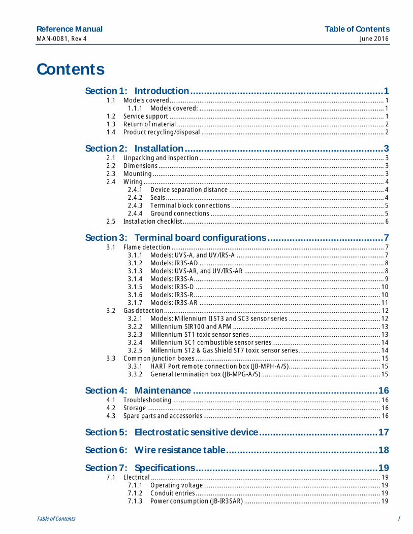
Contents Section 1: Introduction ...................................................................... 1
1.1 Models covered ................................................................................................................... 1 1.1.1 Models covered: ................................................................................................... 1
1.2 Service support ................................................................................................................... 1 1.3 Return of material ............................................................................................................... 2 1.4 Product recycling/disposal .................................................................................................. 2
Section 2: Installation ........................................................................ 3 2.1 Unpacking and inspection ................................................................................................... 3 2.2 Dimensions ......................................................................................................................... 3 2.3 Mounting ............................................................................................................................ 3 2.4 Wiring ................................................................................................................................. 4
2.4.1 Device separation distance ................................................................................... 4 2.4.2 Seals ..................................................................................................................... 4 2.4.3 Terminal block connections .................................................................................. 5 2.4.4 Ground connections ............................................................................................. 5
2.5 Installation checklist ............................................................................................................ 6
Section 3: Terminal board configurations .......................................... 7 3.1 Flame detection .................................................................................................................. 7
3.1.1 Models: UVS-A, and UV/IRS-A ............................................................................... 7 3.1.2 Models: IR3S-AD ................................................................................................... 8 3.1.3 Models: UVS-AR, and UV/IRS-AR ........................................................................... 8 3.1.4 Models: IR3S-A ...................................................................................................... 9 3.1.5 Models: IR3S-D ................................................................................................... 10 3.1.6 Models: IR3S-R .................................................................................................... 10 3.1.7 Models: IR3S-AR ................................................................................................. 11
3.2 Gas detection .................................................................................................................... 12 3.2.1 Models: Millennium II ST3 and SC3 sensor series ................................................. 12 3.2.2 Millennium SIR100 and APM ............................................................................... 13 3.2.3 Millennium ST1 toxic sensor series ...................................................................... 13 3.2.4 Millennium SC1 combustible sensor series .......................................................... 14 3.2.5 Millennium ST2 & Gas Shield ST7 toxic sensor series ............................................ 14
3.3 Common junction boxes ................................................................................................... 15 3.3.1 HART Port remote connection box (JB-MPH-A/S)................................................. 15 3.3.2 General termination box (JB-MPG-A/S) ................................................................ 15
Section 4: Maintenance ................................................................... 16 4.1 Troubleshooting ............................................................................................................... 16 4.2 Storage ............................................................................................................................. 16 4.3 Spare parts and accessories ............................................................................................... 16
Section 5: Electrostatic sensitive device ........................................... 17
Section 6: Wire resistance table ....................................................... 18
Section 7: Specifications .................................................................. 19 7.1 Electrical ........................................................................................................................... 19
7.1.1 Operating voltage ............................................................................................... 19 7.1.2 Conduit entries ................................................................................................... 19 7.1.3 Power consumption (JB-IR3SAR) ......................................................................... 19
Introduction Reference Manual June 2016 MAN-0081, Rev 5
II Table of Contents
7.1.4 Relay contacts (JB-IR3SAR) .................................................................................. 19 7.2 Environmental................................................................................................................... 19
7.2.1 Storage temperature .......................................................................................... 19 7.2.2 Operating temperature ...................................................................................... 19 7.2.3 Relative humidity ................................................................................................ 19 7.2.4 Metallurgy (housing) .......................................................................................... 19 7.2.5 Ingress protection............................................................................................... 19 7.2.6 Weight ............................................................................................................... 19
7.3 Warranty ........................................................................................................................... 19
Section 8: Certifications ................................................................... 20 8.1 North America................................................................................................................... 20
Section 9: Ordering information ...................................................... 21
Reference Manual Introduction MAN-0081, Rev 5 June 2016
Introduction 1
Section 1: Introduction 1.1 Models covered
The Net Safety JB series junction box is a multi-purpose junction box that is used with numerous Net Safety products. It can be used as a termination box for flame detectors or for remote mounting gas sensors from transmitters. It is available in copper-free Aluminum or 316 Stainless Steel.
1.1.1 Models covered:
· JB-IR3SAR - Used with IR3S-AR flame detectors to provide 4–20 mA analog and relay outputs
· JB-MPD - Used for remote mounting of Millennium II combustible (SC3) and toxic (ST3) gas sensors, Millennium combustible (SIR100) IR sensors, and APM sensors
· JB-MPG - General junction box used to separate Millennium toxic (ST2), Millennium combustible (SC1100), and Gas Shield sensors from their transmitter
· JB-MPH - Used to separate the HART® Port (HPT-001) from the HART device
· JB-MPNS - Used with the IR3S-A, UVS-A, and UV/IRS-A flame detectors and separated Millennium toxic sensors (ST1); includes current loop test jacks
· JB-MPR - Used with UVS-AR and UV/IRS-AR relay models only
· JB-MPR3 - Used with IR3S-R relay models only
· JB-MPS - Used with UVS-A and UV/IRS-A flame detectors only, includes magnetic switch for manual VI testing
1.2 Service support Technical support for this product can be provided by contacting your local Emerson™ Process Management/Net Safety representative or by contacting the Net Safety Technical Support department at +1 866 347 3427 or [email protected].
Introduction Reference Manual June 2016 MAN-0081, Rev 5
2 Introduction
1.3 Return of material To expedite the repair and return of this product, proper communication between the customer and the factory is important. Before returning a product for repair, call +1866 347 3427 or e-mail [email protected] for a Material Return Authorization (MRA) number.
On the return of the equipment, include the following information:
1. MRA number provided to you by Emerson
2. Company name and contact information
3. Purchase order, from your company, authorizing repairs or request for quote
Ship all equipment, prepaid to:
Emerson Process Management 6021 Innovation Blvd. Shakopee, MN 55379 Mark all packages with Return for Repair and include MRA number
Pack items to protect them from damage and use anti-static bags or aluminum-backed cardboard as protection from electrostatic damage.
All equipment must be shipped prepaid. Collect shipments will not be accepted.
1.4 Product recycling/disposal Recycling of equipment and packaging should be taken into consideration and disposed of in accordance with local and national legislations/regulations.
Reference Manual Installation MAN-0081, Rev 5 June 2016
Installation 3
Section 2: Installation 2.1 Unpacking and inspection
Carefully remove all of the components from the packaging and verify them against the enclosed packing list. Inspect all components for any obvious damage such as broken or loose parts. If you find any components missing or damaged, notify your local Net Safety representative or the factory immediately.
Recycling of packaging should be taken into consideration and disposed of in accordance with local and national legislations/regulations.
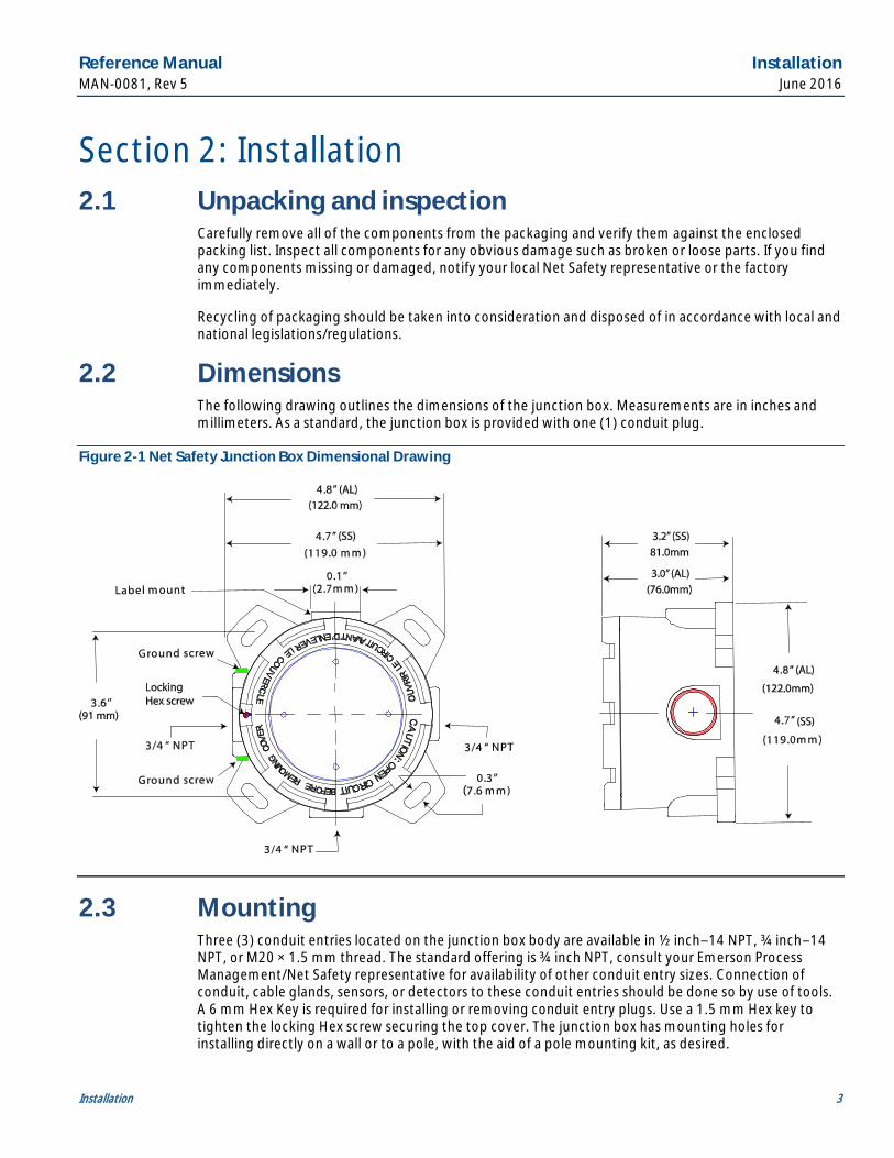
2.2 Dimensions The following drawing outlines the dimensions of the junction box. Measurements are in inches and millimeters. As a standard, the junction box is provided with one (1) conduit plug.
Figure 2-1 Net Safety Junction Box Dimensional Drawing
2.3 Mounting Three (3) conduit entries located on the junction box body are available in ½ inch–14 NPT, ¾ inch–14 NPT, or M20 × 1.5 mm thread. The standard offering is ¾ inch NPT, consult your Emerson Process Management/Net Safety representative for availability of other conduit entry sizes. Connection of conduit, cable glands, sensors, or detectors to these conduit entries should be done so by use of tools. A 6 mm Hex Key is required for installing or removing conduit entry plugs. Use a 1.5 mm Hex key to tighten the locking Hex screw securing the top cover. The junction box has mounting holes for installing directly on a wall or to a pole, with the aid of a pole mounting kit, as desired.
Installation Reference Manual June 2016 MAN-0081, Rev 5
4 Installation
2.4 Wiring
Failure to follow these installation guidelines could result in death or serious injury. Ensure that only qualified personnel perform the installation.
Electrical shock could cause death or serious injury. Use extreme caution when making contact with the leads and terminals.
Do not open the junction box enclosure when in a classified area or when an explosive atmosphere may be present unless the power to the sensor has been removed.
Prior to touching the painted enclosure surface or non-metallic labels, dispel any charge in your body or equipment by touching a grounded metal surface to prevent the generation of a spark.
Installation shall be in accordance with the manufacturer's instructions and the National Electrical Code® (NEC), ANSI/NFPA 70, the Canadian Electrical Code C22.1, or EN60079-14, as applicable.
The use of shielded cable is highly recommended to protect against interference caused by extraneous electrical or electromagnetic ‘noise’. To meet EN/IEC61326 EMC requirements, multi-conductor braid shield cable is recommended. Connection of conduit or cable glands should be done so by use of tools.
In applications where the wiring is installed in conduit, the conduit must not be used for wiring to other electrical equipment.
The junction box may be susceptible to ESD. Refer to Section 5 for further information on proper handling of this equipment.
The temperature rating of the wires connected to the junction box must be greater than 212 °F (100 °C).
2.4.1 Device separation distance The maximum separation distance between the junction box and the connected device is limited by the resistance of the connected wiring, which is a function of the gauge of the wire being used. Net Safety recommends that separation must not exceed 2000 feet (610 meters) while using 16 AWG (1.31 mm2) wire. The Net Safety Millennium SC1100 combustible sensor should not be separated more than 150 feet (46 meters). Refer to Section 6 for wire gauges and resistance values.
2.4.2 Seals
To fully avoid any environmental exposure, the use of seals is recommended, especially for installations that use high-pressure or steam cleaning devices in proximity to the junction box.
Water-proof and explosion-proof conduit seals are recommended to prevent water accumulation within the enclosure.
Seals should be located as close to the device as possible and not more than 18-in. (46cm) away; seal all conduits within 18-in. (46 cm). Consult the local electrical code for specific requirements.
Reference Manual Installation MAN-0081, Rev 5 June 2016
Installation 5
Explosion proof installations may require an additional seal where the conduit enters a non-hazardous area. Ensure conformity with local wiring codes.
When pouring a seal, use a fiber dam to ensure proper formation of the seal. Seals should never be poured at temperatures below freezing. Always refer to the seal manufacturers recommendations.
The jacket and shielding of the cable should be stripped back to permit the seal to form around the individual wires. This will prevent air, gas, and water leakage through the inside of the shield and into the enclosure.
It is recommended that explosion-proof drains and conduit breathers be used. In some applications, alternate changes in temperature and barometric pressure can cause breathing which allows moist air to enter and circulate inside the conduit. Joints in the conduit system are seldom tight enough to prevent this breathing.
Threaded connections on the enclosure between the housing and conduit pipe need to be sealed with thread tape, such as Teflon tape, or something similar.
The conduit openings are gauged using an L-1 gauge to +½ to 2 turn tolerance.
Field maintenance or servicing on the junction box is not recommended. If there are any issues, concerns, or warranty information required, contact Net Safety.
2.4.3 Terminal block connections
Do not open the transmitter, sensor, or junction box enclosure when in a classified area or when an explosive atmosphere may be present unless the power to the sensor has been removed.
Prior to touching the painted enclosure surface or non-metallic labels, dispel any charge in your body or equipment by touching a grounded metal surface to prevent the generation of a spark.
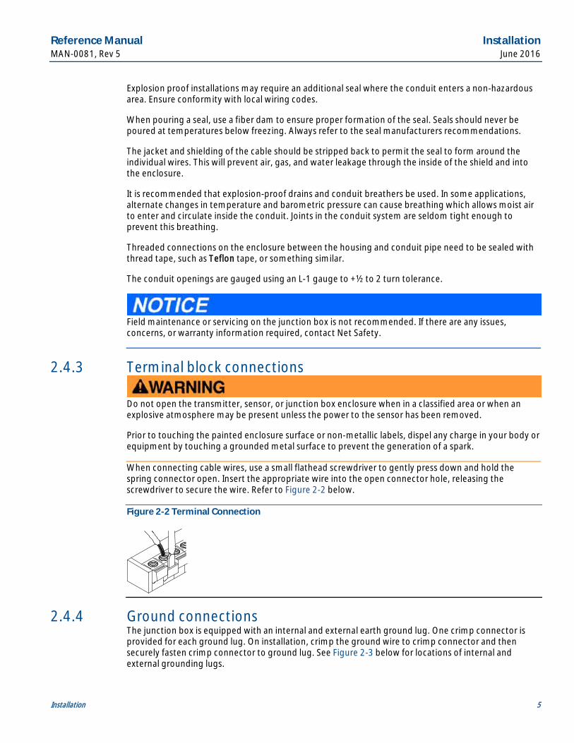
When connecting cable wires, use a small flathead screwdriver to gently press down and hold the spring connector open. Insert the appropriate wire into the open connector hole, releasing the screwdriver to secure the wire. Refer to Figure 2-2 below.
Figure 2-2 Terminal Connection
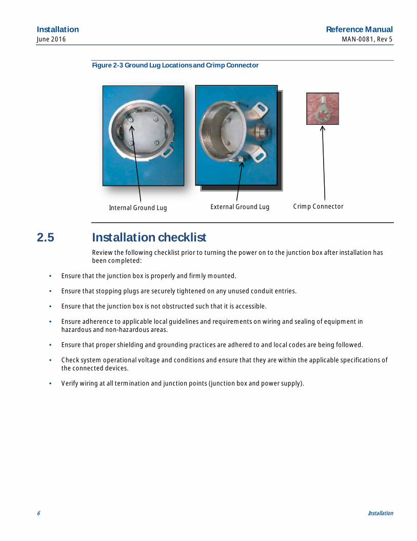
2.4.4 Ground connections The junction box is equipped with an internal and external earth ground lug. One crimp connector is provided for each ground lug. On installation, crimp the ground wire to crimp connector and then securely fasten crimp connector to ground lug. See Figure 2-3 below for locations of internal and external grounding lugs.
Installation Reference Manual June 2016 MAN-0081, Rev 5
6 Installation
Figure 2-3 Ground Lug Locations and Crimp Connector
2.5 Installation checklist Review the following checklist prior to turning the power on to the junction box after installation has been completed:
· Ensure that the junction box is properly and firmly mounted.
· Ensure that stopping plugs are securely tightened on any unused conduit entries.
· Ensure that the junction box is not obstructed such that it is accessible.
· Ensure adherence to applicable local guidelines and requirements on wiring and sealing of equipment in hazardous and non-hazardous areas.
· Ensure that proper shielding and grounding practices are adhered to and local codes are being followed.
· Check system operational voltage and conditions and ensure that they are within the applicable specifications of the connected devices.
· Verify wiring at all termination and junction points (junction box and power supply).
Internal Ground Lug External Ground Lug Crimp Connector
Reference Manual Terminal board configurations MAN-0081, Rev 5 June 2016
Terminal board configurations 7
Section 3: Terminal board configurations There are multiple terminal board configurations facilitated by the JB series junction box. This allows effective, safe, and accurate terminations and sensor separation requirements across the Net Safety product line. These configurations are outlined below.
Each model of the multi-purpose junction box contains a PCB with different components for features that are applicable to specific models of Net Safety products, such as meter test jacks or a magnetic switch. Refer to the specific transmitter, detector, or sensor manuals for detailed instructions about using these options.
3.1 Flame detection
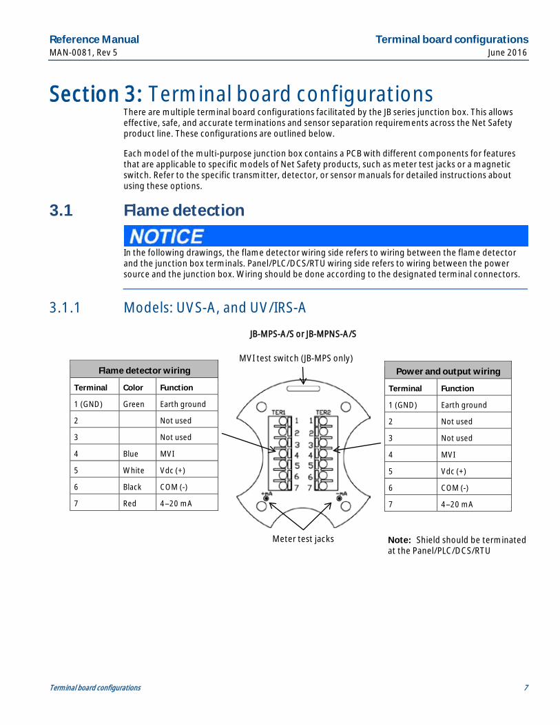
In the following drawings, the flame detector wiring side refers to wiring between the flame detector and the junction box terminals. Panel/PLC/DCS/RTU wiring side refers to wiring between the power source and the junction box. Wiring should be done according to the designated terminal connectors.
3.1.1 Models: UVS-A, and UV/IRS-A
Flame detector wiring
Terminal Color Function
1 (GND) Green Earth ground
2 Not used
3 Not used
4 Blue MVI
5 White Vdc (+)
6 Black COM (-)
7 Red 4–20 mA
Power and output wiring
Terminal Function
1 (GND) Earth ground
2 Not used
3 Not used
4 MVI
5 Vdc (+)
6 COM (-)
7 4–20 mA
Meter test jacks
MVI test switch (JB-MPS only)
JB-MPS-A/S or JB-MPNS-A/S
Note: Shield should be terminated at the Panel/PLC/DCS/RTU
Terminal board configurations Reference Manual June 2016 MAN-0081, Rev 5
8 Terminal board configurations
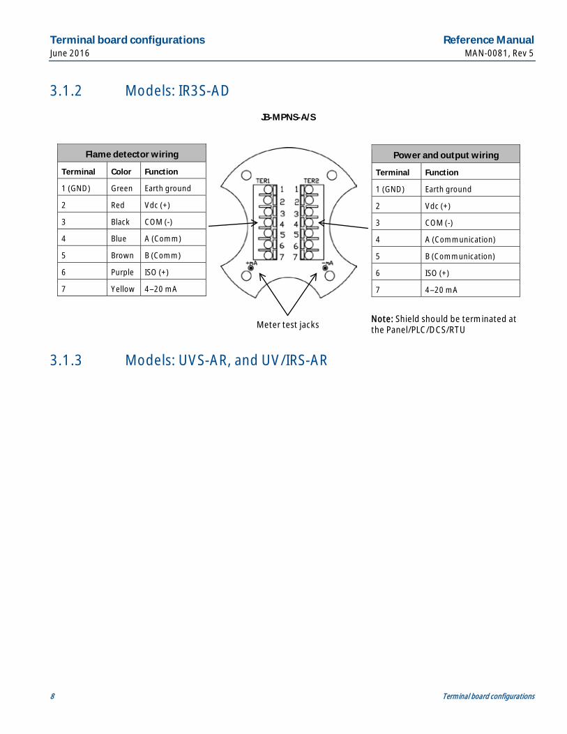
3.1.2 Models: IR3S-AD
3.1.3 Models: UVS-AR, and UV/IRS-AR
Flame detector wiring
Terminal Color Function
1 (GND) Green Earth ground
2 Red Vdc (+)
3 Black COM (-)
4 Blue A (Comm)
5 Brown B (Comm)
6 Purple ISO (+)
7 Yellow 4–20 mA
Power and output wiring
Terminal Function
1 (GND) Earth ground
2 Vdc (+)
3 COM (-)
4 A (Communication)
5 B (Communication)
6 ISO (+)
7 4–20 mA
Meter test jacks
JB-MPNS-A/S
Note: Shield should be terminated at the Panel/PLC/DCS/RTU
Reference Manual Terminal board configurations MAN-0081, Rev 5 June 2016
Terminal board configurations 9
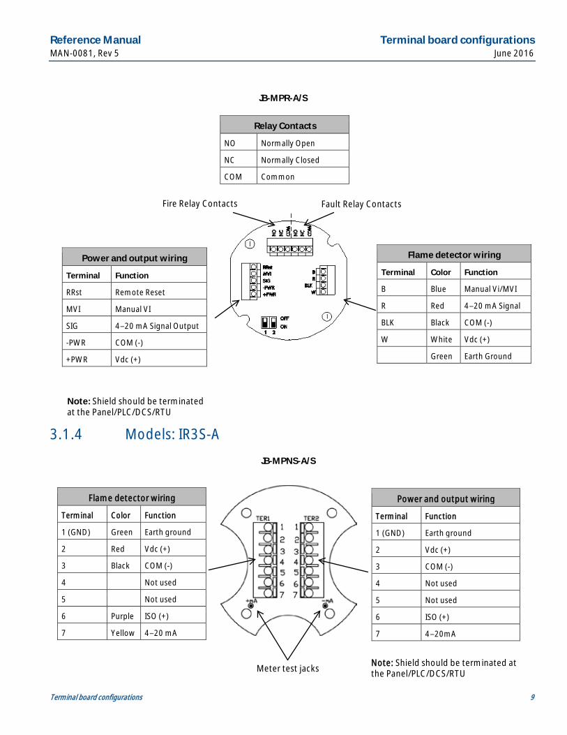
3.1.4 Models: IR3S-A
Flame detector wiring
Terminal Color Function
1 (GND) Green Earth ground
2 Red Vdc (+)
3 Black COM (-)
4 Not used
5 Not used
6 Purple ISO (+)
7 Yellow 4–20 mA
Power and output wiring
Terminal Function
1 (GND) Earth ground
2 Vdc (+)
3 COM (-)
4 Not used
5 Not used
6 ISO (+)
7 4–20mA
Meter test jacks
JB-MPNS-A/S
Note: Shield should be terminated at the Panel/PLC/DCS/RTU
Flame detector wiring
Terminal Color Function
B Blue Manual Vi/MVI
R Red 4–20 mA Signal
BLK Black COM (-)
W White Vdc (+)
Green Earth Ground
Power and output wiring
Terminal Function
RRst Remote Reset
MVI Manual VI
SIG 4–20 mA Signal Output
-PWR COM (-)
+PWR Vdc (+)
Fire Relay Contacts
JB-MPR-A/S
Note: Shield should be terminated at the Panel/PLC/DCS/RTU
Relay Contacts
NO Normally Open
NC Normally Closed
COM Common
Fault Relay Contacts
Terminal board configurations Reference Manual June 2016 MAN-0081, Rev 5
10 Terminal board configurations
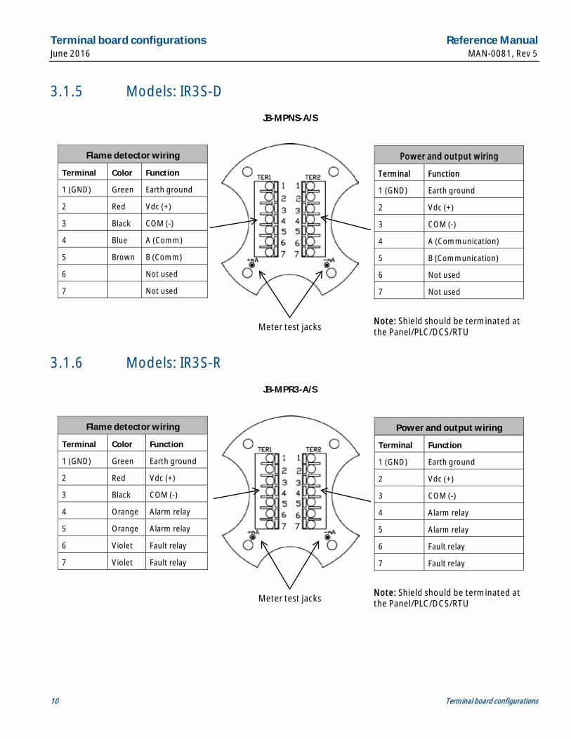
3.1.5 Models: IR3S-D
3.1.6 Models: IR3S-R
Flame detector wiring
Terminal Color Function
1 (GND) Green Earth ground
2 Red Vdc (+)
3 Black COM (-)
4 Orange Alarm relay
5 Orange Alarm relay
6 Violet Fault relay
7 Violet Fault relay
Power and output wiring
Terminal Function
1 (GND) Earth ground
2 Vdc (+)
3 COM (-)
4 Alarm relay
5 Alarm relay
6 Fault relay
7 Fault relay
Meter test jacks
JB-MPR3-A/S
Note: Shield should be terminated at the Panel/PLC/DCS/RTU
Flame detector wiring
Terminal Color Function
1 (GND) Green Earth ground
2 Red Vdc (+)
3 Black COM (-)
4 Blue A (Comm)
5 Brown B (Comm)
6 Not used
7 Not used
Power and output wiring
Terminal Function
1 (GND) Earth ground
2 Vdc (+)
3 COM (-)
4 A (Communication)
5 B (Communication)
6 Not used
7 Not used
Meter test jacks
JB-MPNS-A/S
Note: Shield should be terminated at the Panel/PLC/DCS/RTU
Reference Manual Terminal board configurations MAN-0081, Rev 5 June 2016
Terminal board configurations 11
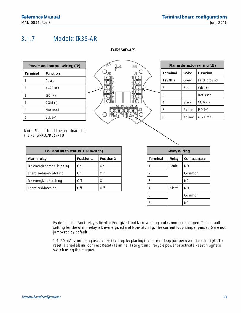
3.1.7 Models: IR3S-AR
By default the Fault relay is fixed as Energized and Non-latching and cannot be changed. The default setting for the Alarm relay is De-energized and Non-latching. The current loop jumper pins at J6 are not jumpered by default.
If 4–20 mA is not being used close the loop by placing the current loop jumper over pins (short J6). To reset latched alarm, connect Reset (Terminal 1) to ground, recycle power or activate Reset magnetic switch using the magnet.
Flame detector wiring (J1)
Terminal Color Function
1 (GND) Green Earth ground
2 Red Vdc (+)
3 Not used
4 Black COM (-)
5 Purple ISO (+)
6 Yellow 4–20 mA
Power and output wiring (J2)
Terminal Function
1 Reset
2 4–20 mA
3 ISO (+)
4 COM (-)
5 Not used
6 Vdc (+)
JB-IR3SAR-A/S
Note: Shield should be terminated at the Panel/PLC/DCS/RTU
Relay wiring
Terminal Relay Contact state
1 Fault NO
2 Common
3 NC
4 Alarm NO
5 Common
6 NC
Coil and latch status (DIP switch)
Alarm relay Position 1 Position 2
De-energized/non-latching On On
Energized/non-latching On Off
De-energized/latching Off On
Energized/latching Off Off
Terminal board configurations Reference Manual June 2016 MAN-0081, Rev 5
12 Terminal board configurations
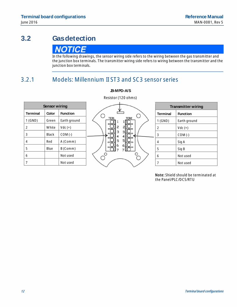
3.2 Gas detection
In the following drawings, the sensor wiring side refers to the wiring between the gas transmitter and the junction box terminals. The transmitter wiring side refers to wiring between the transmitter and the junction box terminals.
3.2.1 Models: Millennium II ST3 and SC3 sensor series
Sensor wiring
Terminal Color Function
1 (GND) Green Earth ground
2 White Vdc (+)
3 Black COM (-)
4 Red A (Comm)
5 Blue B (Comm)
6 Not used
7 Not used
Transmitter wiring
Terminal Function
1 (GND) Earth ground
2 Vdc (+)
3 COM (-)
4 Sig A
5 Sig B
6 Not used
7 Not used
Resistor (120 ohms)
JB-MPD-A/S
Note: Shield should be terminated at the Panel/PLC/DCS/RTU
Reference Manual Terminal board configurations MAN-0081, Rev 5 June 2016
Terminal board configurations 13
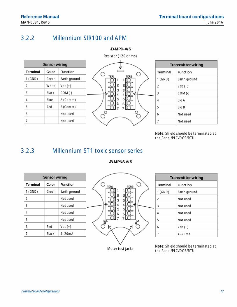
3.2.2 Millennium SIR100 and APM
3.2.3 Millennium ST1 toxic sensor series
Sensor wiring
Terminal Color Function
1 (GND) Green Earth ground
2 Not used
3 Not used
4 Not used
5 Not used
6 Red Vdc (+)
7 Black 4–20mA
Transmitter wiring
Terminal Function
1 (GND) Earth ground
2 Not used
3 Not used
4 Not used
5 Not used
6 Vdc (+)
7 4–20mA
Meter test jacks
JB-MPNS-A/S
Note: Shield should be terminated at the Panel/PLC/DCS/RTU
Sensor wiring
Terminal Color Function
1 (GND) Green Earth ground
2 White Vdc (+)
3 Black COM (-)
4 Blue A (Comm)
5 Red B (Comm)
6 Not used
7 Not used
Transmitter wiring
Terminal Function
1 (GND) Earth ground
2 Vdc (+)
3 COM (-)
4 Sig A
5 Sig B
6 Not used
7 Not used
Resistor (120 ohms)
JB-MPD-A/S
Note: Shield should be terminated at the Panel/PLC/DCS/RTU
Terminal board configurations Reference Manual June 2016 MAN-0081, Rev 5
14 Terminal board configurations
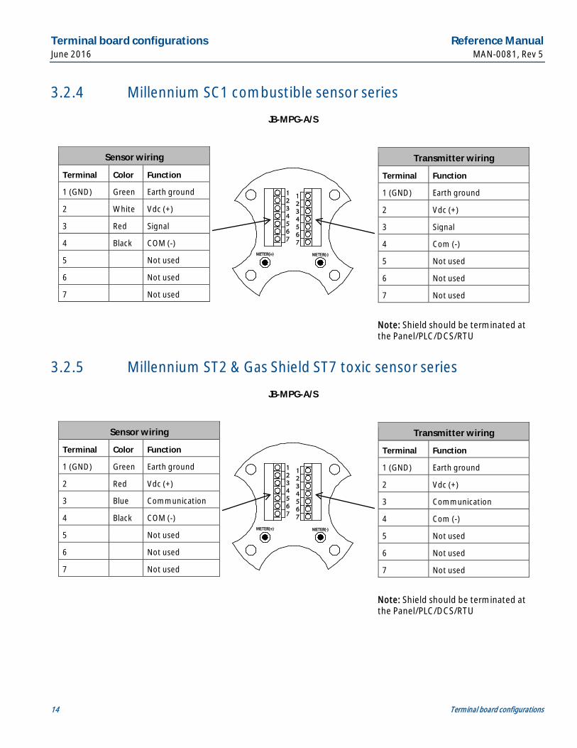
3.2.4 Millennium SC1 combustible sensor series
3.2.5 Millennium ST2 & Gas Shield ST7 toxic sensor series
Sensor wiring
Terminal Color Function
1 (GND) Green Earth ground
2 Red Vdc (+)
3 Blue Communication
4 Black COM (-)
5 Not used
6 Not used
7 Not used
Transmitter wiring
Terminal Function
1 (GND) Earth ground
2 Vdc (+)
3 Communication
4 Com (-)
5 Not used
6 Not used
7 Not used
JB-MPG-A/S
Note: Shield should be terminated at the Panel/PLC/DCS/RTU
Sensor wiring
Terminal Color Function
1 (GND) Green Earth ground
2 White Vdc (+)
3 Red Signal
4 Black COM (-)
5 Not used
6 Not used
7 Not used
Transmitter wiring
Terminal Function
1 (GND) Earth ground
2 Vdc (+)
3 Signal
4 Com (-)
5 Not used
6 Not used
7 Not used
JB-MPG-A/S
Note: Shield should be terminated at the Panel/PLC/DCS/RTU
Reference Manual Terminal board configurations MAN-0081, Rev 5 June 2016
Terminal board configurations 15
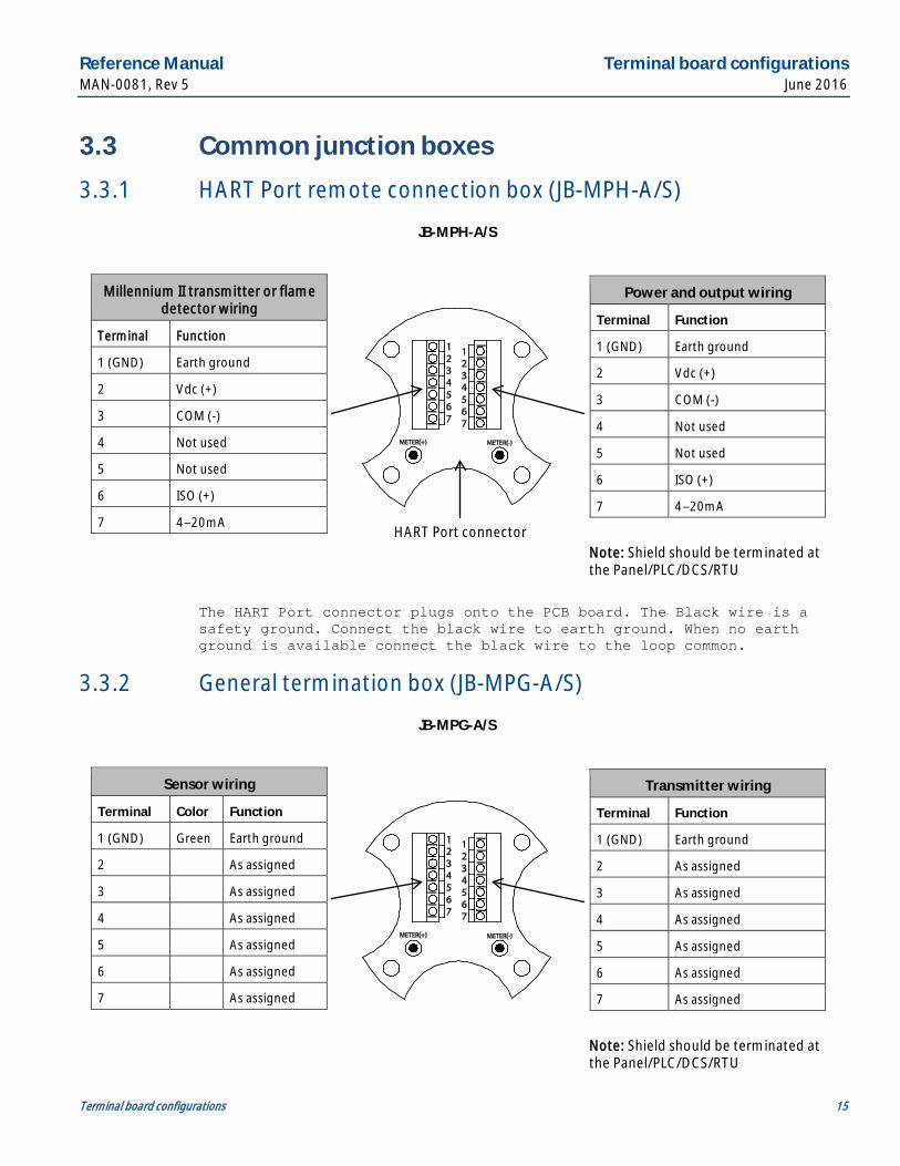
3.3 Common junction boxes
3.3.1 HART Port remote connection box (JB-MPH-A/S)
The HART Port connector plugs onto the PCB board. The Black wire is a safety ground. Connect the black wire to earth ground. When no earth ground is available connect the black wire to the loop common.
3.3.2 General termination box (JB-MPG-A/S)
Sensor wiring
Terminal Color Function
1 (GND) Green Earth ground
2 As assigned
3 As assigned
4 As assigned
5 As assigned
6 As assigned
7 As assigned
Transmitter wiring
Terminal Function
1 (GND) Earth ground
2 As assigned
3 As assigned
4 As assigned
5 As assigned
6 As assigned
7 As assigned
JB-MPG-A/S
Note: Shield should be terminated at the Panel/PLC/DCS/RTU
Millennium II transmitter or flame detector wiring
Terminal Function
1 (GND) Earth ground
2 Vdc (+)
3 COM (-)
4 Not used
5 Not used
6 ISO (+)
7 4–20mA
Power and output wiring
Terminal Function
1 (GND) Earth ground
2 Vdc (+)
3 COM (-)
4 Not used
5 Not used
6 ISO (+)
7 4–20mA
JB-MPH-A/S
Note: Shield should be terminated at the Panel/PLC/DCS/RTU
HART Port connector
Maintenance Reference Manual June 2016 MAN-0081, Rev 5
16 Maintenance
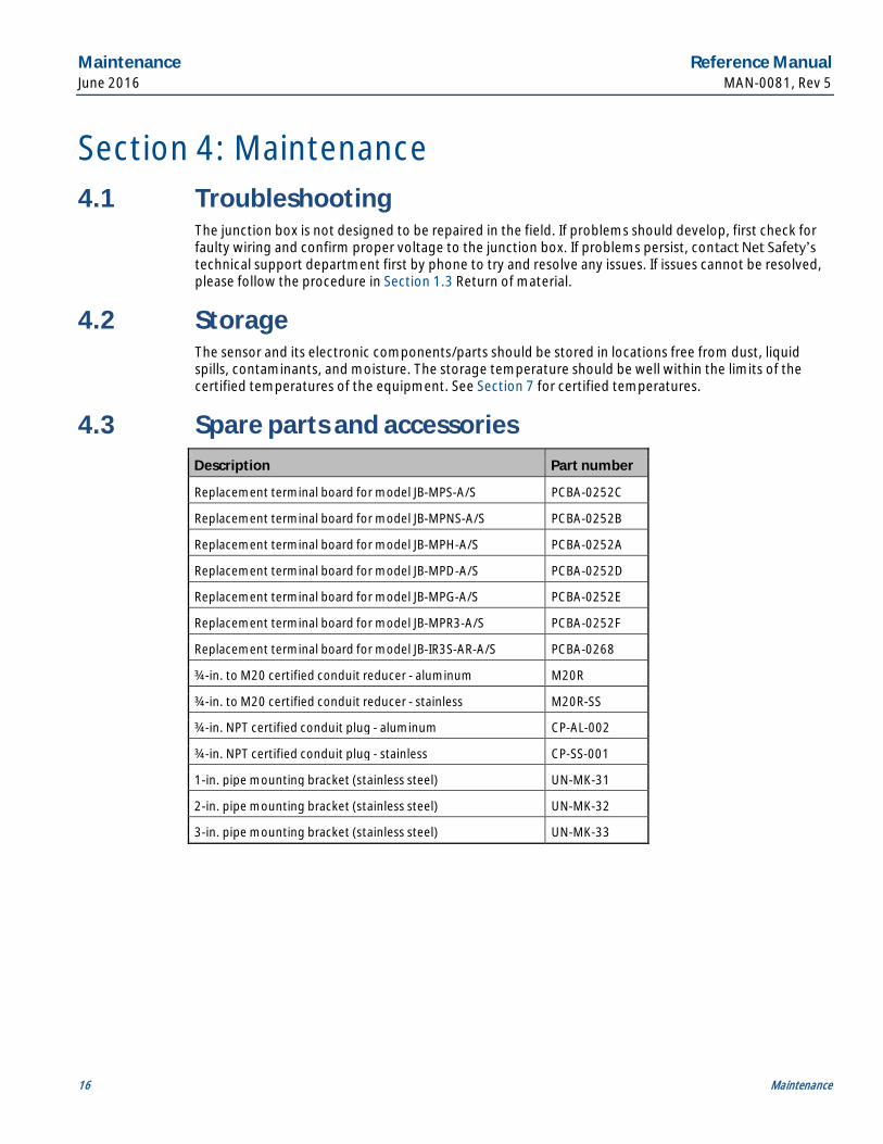
Section 4: Maintenance 4.1 Troubleshooting
The junction box is not designed to be repaired in the field. If problems should develop, first check for faulty wiring and confirm proper voltage to the junction box. If problems persist, contact Net Safety’s technical support department first by phone to try and resolve any issues. If issues cannot be resolved, please follow the procedure in Section 1.3 Return of material.
4.2 Storage The sensor and its electronic components/parts should be stored in locations free from dust, liquid spills, contaminants, and moisture. The storage temperature should be well within the limits of the certified temperatures of the equipment. See Section 7 for certified temperatures.
4.3 Spare parts and accessories Description Part number
Replacement terminal board for model JB-MPS-A/S PCBA-0252C
Replacement terminal board for model JB-MPNS-A/S PCBA-0252B
Replacement terminal board for model JB-MPH-A/S PCBA-0252A
Replacement terminal board for model JB-MPD-A/S PCBA-0252D
Replacement terminal board for model JB-MPG-A/S PCBA-0252E
Replacement terminal board for model JB-MPR3-A/S PCBA-0252F
Replacement terminal board for model JB-IR3S-AR-A/S PCBA-0268
¾-in. to M20 certified conduit reducer - aluminum M20R
¾-in. to M20 certified conduit reducer - stainless M20R-SS
¾-in. NPT certified conduit plug - aluminum CP-AL-002
¾-in. NPT certified conduit plug - stainless CP-SS-001
1-in. pipe mounting bracket (stainless steel) UN-MK-31
2-in. pipe mounting bracket (stainless steel) UN-MK-32
3-in. pipe mounting bracket (stainless steel) UN-MK-33
Reference Manual Electrostatic sensitive device MAN-0081, Rev 5 June 2016
Electrostatic sensitive device 17
Section 5: Electrostatic sensitive device Definition: Electrostatic discharge (ESD) is the transfer, between bodies, of an electrostatic charge caused by direct contact or induced by an electrostatic field.
The most common cause of ESD is physical contact. Touching an object can cause a discharge of electrostatic energy. If the charge is sufficient and occurs near electronic components, it can damage or destroy those components. In some cases, damage is instantaneous and an immediate malfunction occurs. However, symptoms are not always immediate—performance may be marginal or seemingly normal for an indefinite period of time, followed by a sudden failure.
To eliminate potential ESD damage, review the following guidelines:
· Handle boards by the sides —taking care not to touch electronic components.
· Wear grounded wrist or foot straps, ESD shoes or heel grounders to dissipate unwanted static energy.
· Prior to handling boards, dispel any charge in your body or equipment by touching a grounded metal surface.
· Ensure all components are transported and stored in ESD safe packaging.
· When returning boards, carefully package in the original carton and static protective wrapping.
· Prior to touching the painted enclosure surface or non-metallic labels, dispel any charge in your body or equipment by touching a grounded metal surface to prevent the generation of a spark.
· Ensure ALL personnel are educated and trained in ESD Control Procedures.
In general, exercise accepted and proven precautions normally observed when handling electrostatic sensitive devices.
Wire resistance table Reference Manual June 2016 MAN-0081, Rev 5
18 Wire resistance table
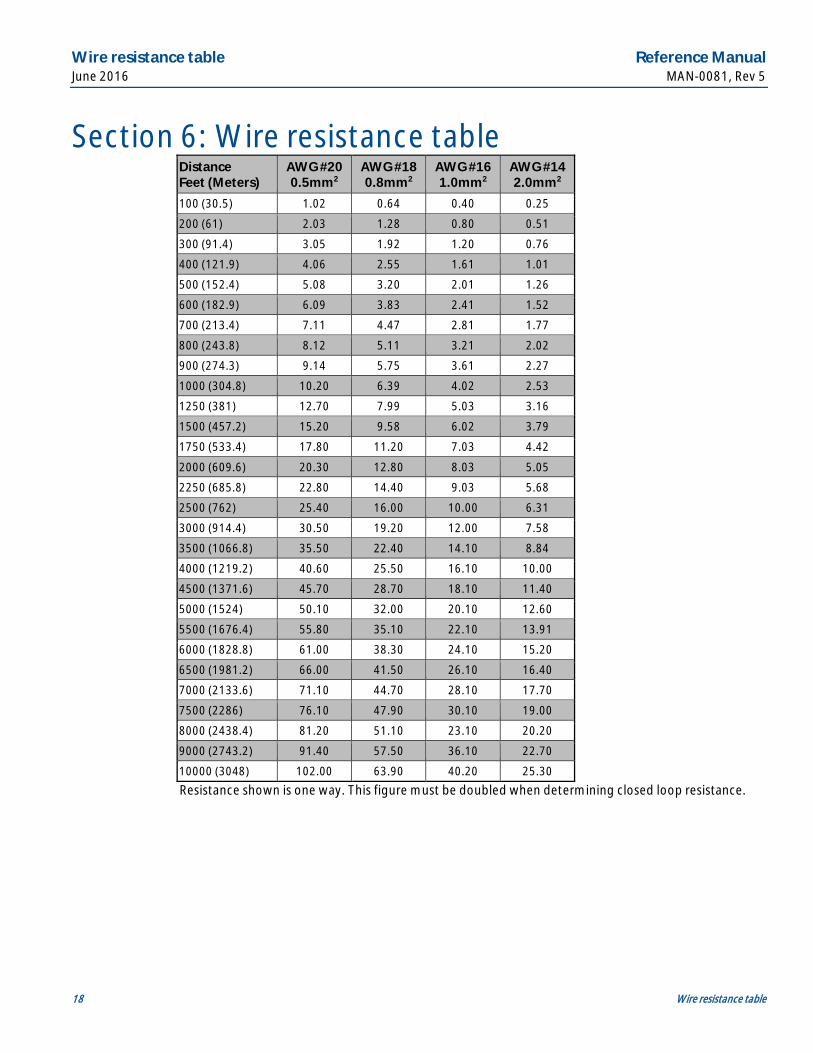
Section 6: Wire resistance table
Resistance shown is one way. This figure must be doubled when determining closed loop resistance.
Distance Feet (Meters)
AWG #20 0.5mm2
AWG #18 0.8mm2
AWG #16 1.0mm2
AWG #14 2.0mm2
100 (30.5) 1.02 0.64 0.40 0.25
200 (61) 2.03 1.28 0.80 0.51
300 (91.4) 3.05 1.92 1.20 0.76
400 (121.9) 4.06 2.55 1.61 1.01
500 (152.4) 5.08 3.20 2.01 1.26
600 (182.9) 6.09 3.83 2.41 1.52
700 (213.4) 7.11 4.47 2.81 1.77
800 (243.8) 8.12 5.11 3.21 2.02
900 (274.3) 9.14 5.75 3.61 2.27
1000 (304.8) 10.20 6.39 4.02 2.53
1250 (381) 12.70 7.99 5.03 3.16
1500 (457.2) 15.20 9.58 6.02 3.79
1750 (533.4) 17.80 11.20 7.03 4.42
2000 (609.6) 20.30 12.80 8.03 5.05
2250 (685.8) 22.80 14.40 9.03 5.68
2500 (762) 25.40 16.00 10.00 6.31
3000 (914.4) 30.50 19.20 12.00 7.58
3500 (1066.8) 35.50 22.40 14.10 8.84
4000 (1219.2) 40.60 25.50 16.10 10.00
4500 (1371.6) 45.70 28.70 18.10 11.40
5000 (1524) 50.10 32.00 20.10 12.60
5500 (1676.4) 55.80 35.10 22.10 13.91
6000 (1828.8) 61.00 38.30 24.10 15.20
6500 (1981.2) 66.00 41.50 26.10 16.40
7000 (2133.6) 71.10 44.70 28.10 17.70
7500 (2286) 76.10 47.90 30.10 19.00
8000 (2438.4) 81.20 51.10 23.10 20.20
9000 (2743.2) 91.40 57.50 36.10 22.70
10000 (3048) 102.00 63.90 40.20 25.30
Reference Manual Specifications MAN-0081, Rev 5 June 2016
Specifications 19
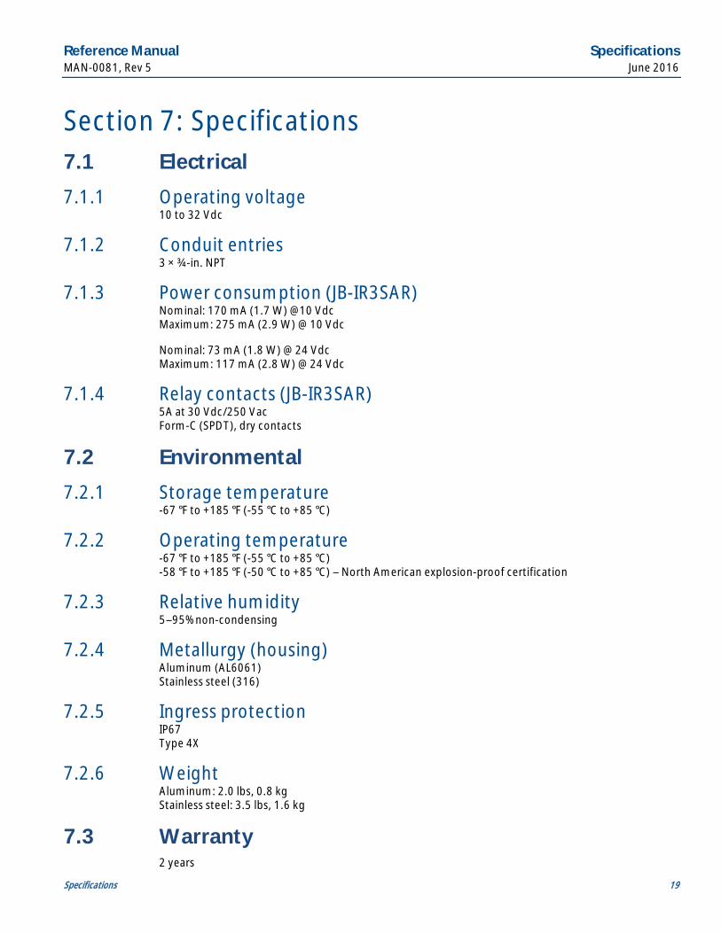
Section 7: Specifications 7.1 Electrical
7.1.1 Operating voltage 10 to 32 Vdc
7.1.2 Conduit entries 3 × ¾-in. NPT
7.1.3 Power consumption (JB-IR3SAR) Nominal: 170 mA (1.7 W) @10 Vdc Maximum: 275 mA (2.9 W) @ 10 Vdc
Nominal: 73 mA (1.8 W) @ 24 Vdc Maximum: 117 mA (2.8 W) @ 24 Vdc
7.1.4 Relay contacts (JB-IR3SAR) 5A at 30 Vdc/250 Vac Form-C (SPDT), dry contacts
7.2 Environmental
7.2.1 Storage temperature -67 °F to +185 °F (-55 °C to +85 °C)
7.2.2 Operating temperature -67 °F to +185 °F (-55 °C to +85 °C) -58 °F to +185 °F (-50 °C to +85 °C) – North American explosion-proof certification
7.2.3 Relative humidity 5–95% non-condensing
7.2.4 Metallurgy (housing) Aluminum (AL6061) Stainless steel (316)
7.2.5 Ingress protection IP67 Type 4X
7.2.6 Weight Aluminum: 2.0 lbs, 0.8 kg Stainless steel: 3.5 lbs, 1.6 kg
7.3 Warranty 2 years
Certifications Reference Manual June 2016 MAN-0081, Rev 5
20 Certifications
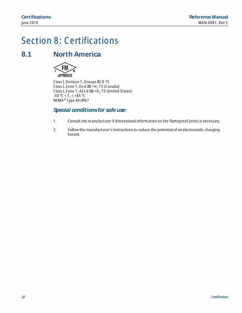
Section 8: Certifications 8.1 North America
Class I, Division 1, Groups BCD T5 Class I, Zone 1, Ex d IIB +H2 T5 (Canada) Class I, Zone 1, AEx d IIB +H2 T5 (United States) -50 °C ≤ Ta ≤ +85 °C NEMA® Type 4X/IP67
Special conditions for safe use:
1. Consult the manufacturer if dimensional information on the flameproof joints is necessary.
2. Follow the manufacturer’s instructions to reduce the potential of an electrostatic charging hazard.
Reference Manual Ordering information MAN-0081, Rev 5 June 2016
Ordering information 21
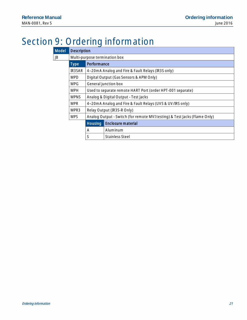
Section 9: Ordering information Model Description
JB Multi-purpose termination box
Type Performance
IR3SAR 4–20mA Analog and Fire & Fault Relays (IR3S only)
MPD Digital Output (Gas Sensors & APM Only)
MPG General junction box
MPH Used to separate remote HART Port (order HPT-001 separate)
MPNS Analog & Digital Output - Test Jacks
MPR 4–20mA Analog and Fire & Fault Relays (UVS & UV/IRS only)
MPR3 Relay Output (IR3S-R Only)
MPS Analog Output - Switch (for remote MVI testing) & Test Jacks (Flame Only)
Housing Enclosure material
A Aluminum
S Stainless Steel

Notes

Reference Manual MAN-0081, Rev 5
June 2016
EmersonProcess.com/FlameGasDetection
Americas Emerson Process Management 6021 Innovation Blvd. Shakopee, MN 55379 T +1 866 347 3427 F +1 952 949 7001 [email protected]
Europe Emerson Process Management AG Neuhofstrasse 19a P.O. Box 1046 CH-6340 Baar Switzerland T + 41 (0) 41 768 6111 F + 41 (0) 41 768 6300 [email protected]
Middle East & Africa Emerson Process Management Emerson FZE Jebel Ali Free Zone Dubai, UAE P.O. Box 17033 T + 971 4 811 8100 F + 971 4 886 5465 [email protected]
AnalyticExpert.com
Twitter.com/Rosemount_News
Asia Pacific Emerson Process Management 1 Pandan Crescent Singapore 128461 Singapore T + 65 777 8211 F + 65 777 0947 [email protected]
Facebook.com/Rosemount
Youtube.com/user/RosemountAnalytical
© 2016 Emerson Process Management. All rights reserved. The Emerson logo is a trademark and service mark of Emerson Electric Co. Net Safety is a trademark of Emerson Process Management. HART is a registered trademark of the FieldComm Group. NEMA is a registered trademark and service mark of the National Electrical Manufacturers Association. National Electrical Code is a registered trademark of National Fire Protection Association, Inc. All other marks are the property of their respective owners. The contents of this publication are presented for information purposes only, and while effort has been made to ensure their accuracy, they are not to be construed as warranties or guarantees, express or implied, regarding the products or services described herein or their use or applicability. All sales are governed by our terms and conditions, which are available on request. We reserve the right to modify or improve the designs or specifications of our products at any time without notice.