nec express5800/r320f configuration guide · nec express5800/r320f configuration guide windows...
TRANSCRIPT
NEC Express5800/R320f
Configuration Guide
Windows model
Introduction
This document contains product and configuration information that will enable you to configure your system. The guide will ensure fast and proper configuration of your NEC Express5800 server.
April 2018
Revision 2.0
NEC Corporation
CONFIGURATION GUIDE – NEC Express5800/R320f / Windows model
NEC Corporation Revision 2.0, April 2018 2
Contents
TECHNICAL SPECIFICATION ........................................................................................ 3
Specification .......................................................................................................................................... 3
EXTERNAL VIEWS ......................................................................................................... 4
Front and Rear Views ........................................................................................................................... 4
Dimensions (mm) .................................................................................................................................. 7
CONFIGURATION DIAGRAM ......................................................................................... 8
SERVER CONFIGURATION ......................................................................................... 10
1 Base Models ................................................................................................................................. 10
2 2nd Processor .............................................................................................................................. 10
3 Memory ......................................................................................................................................... 10
4 Internal Hard Disk Drives ............................................................................................................ 11
5 Optical Drive ................................................................................................................................. 12
6 PCI Card ........................................................................................................................................ 12
6.1 LAN Controller ..................................................................................................................... 12 6.2 Fibre Channel / SAS Controller ........................................................................................... 12
7 Other Add-in Components .......................................................................................................... 14
7.1 Input Devices ....................................................................................................................... 14
8 Add-on Components ................................................................................................................... 14
8.1 17-inch LCD Console Drawer .............................................................................................. 14 8.2 KVM Switch ......................................................................................................................... 14 8.3 Flash FDD............................................................................................................................ 14 8.4 Tower Conversion Kit ........................................................................................................... 15 8.5 Dust Proof Filter ................................................................................................................... 15 8.6 External Tape Drives ........................................................................................................... 15 8.7 RDX Cartridge ..................................................................................................................... 17
REFERENCES............................................................................................................... 18
Server Management ............................................................................................................................ 18
Supported PCI Cards and Installable Slots ...................................................................................... 19
Notes for using Hyper-V ..................................................................................................................... 20
About Windows Server License Count on ft Server ........................................................................ 21
Copyright Notice and Liability Disclaimer ........................................................................................ 22
REVISION HISTORY ..................................................................................................... 23
CONFIGURATION GUIDE – NEC Express5800/R320f / Windows model
NEC Corporation Revision 2.0, April 2018 3
Technical Specification
Specification
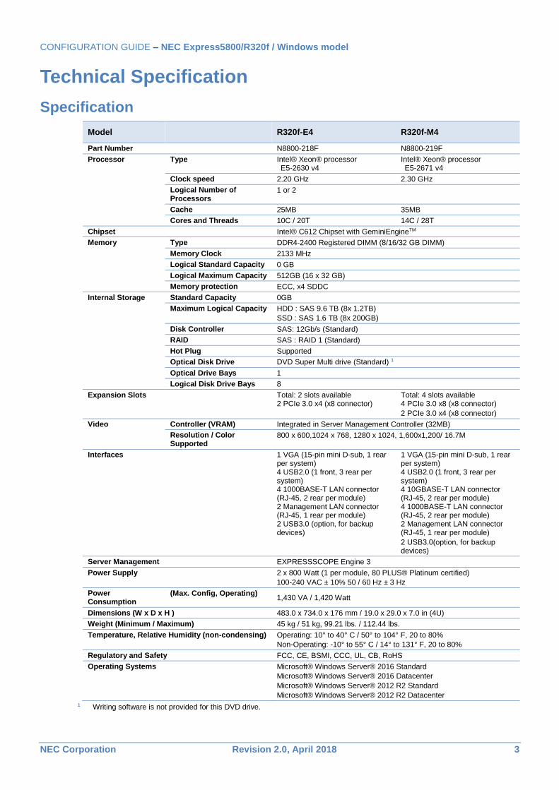
Model R320f-E4 R320f-M4
Part Number N8800-218F N8800-219F
Processor Type Intel® Xeon® processor E5-2630 v4
Intel® Xeon® processor E5-2671 v4
Clock speed 2.20 GHz 2.30 GHz
Logical Number of Processors
1 or 2
Cache 25MB 35MB
Cores and Threads 10C / 20T 14C / 28T
Chipset Intel® C612 Chipset with GeminiEngineTM
Memory Type DDR4-2400 Registered DIMM (8/16/32 GB DIMM)
Memory Clock 2133 MHz
Logical Standard Capacity 0 GB
Logical Maximum Capacity 512GB (16 x 32 GB)
Memory protection ECC, x4 SDDC
Internal Storage Standard Capacity 0GB
Maximum Logical Capacity HDD : SAS 9.6 TB (8x 1.2TB)
SSD : SAS 1.6 TB (8x 200GB)
Disk Controller SAS: 12Gb/s (Standard)
RAID SAS : RAID 1 (Standard)
Hot Plug Supported
Optical Disk Drive DVD Super Multi drive (Standard) 1
Optical Drive Bays 1
Logical Disk Drive Bays 8
Expansion Slots Total: 2 slots available 2 PCIe 3.0 x4 (x8 connector)
Total: 4 slots available 4 PCIe 3.0 x8 (x8 connector)
2 PCIe 3.0 x4 (x8 connector)
Video Controller (VRAM) Integrated in Server Management Controller (32MB)
Resolution / Color Supported
800 x 600,1024 x 768, 1280 x 1024, 1,600x1,200/ 16.7M
Interfaces 1 VGA (15-pin mini D-sub, 1 rear per system) 4 USB2.0 (1 front, 3 rear per system) 4 1000BASE-T LAN connector (RJ-45, 2 rear per module) 2 Management LAN connector (RJ-45, 1 rear per module) 2 USB3.0 (option, for backup devices)
1 VGA (15-pin mini D-sub, 1 rear per system) 4 USB2.0 (1 front, 3 rear per system) 4 10GBASE-T LAN connector (RJ-45, 2 rear per module) 4 1000BASE-T LAN connector (RJ-45, 2 rear per module) 2 Management LAN connector (RJ-45, 1 rear per module)
2 USB3.0(option, for backup devices)
Server Management EXPRESSSCOPE Engine 3
Power Supply 2 x 800 Watt (1 per module, 80 PLUS® Platinum certified)
100-240 VAC ± 10% 50 / 60 Hz ± 3 Hz
Power Consumption
(Max. Config, Operating) 1,430 VA / 1,420 Watt
Dimensions (W x D x H ) 483.0 x 734.0 x 176 mm / 19.0 x 29.0 x 7.0 in (4U)
Weight (Minimum / Maximum) 45 kg / 51 kg, 99.21 lbs. / 112.44 lbs.
Temperature, Relative Humidity (non-condensing) Operating: 10° to 40° C / 50° to 104° F, 20 to 80%
Non-Operating: -10° to 55° C / 14° to 131° F, 20 to 80%
Regulatory and Safety FCC, CE, BSMI, CCC, UL, CB, RoHS
Operating Systems Microsoft® Windows Server® 2016 Standard
Microsoft® Windows Server® 2016 Datacenter
Microsoft® Windows Server® 2012 R2 Standard
Microsoft® Windows Server® 2012 R2 Datacenter
1 Writing software is not provided for this DVD drive.
CONFIGURATION GUIDE – NEC Express5800/R320f / Windows model
NEC Corporation Revision 2.0, April 2018 4
External Views
Front and Rear Views
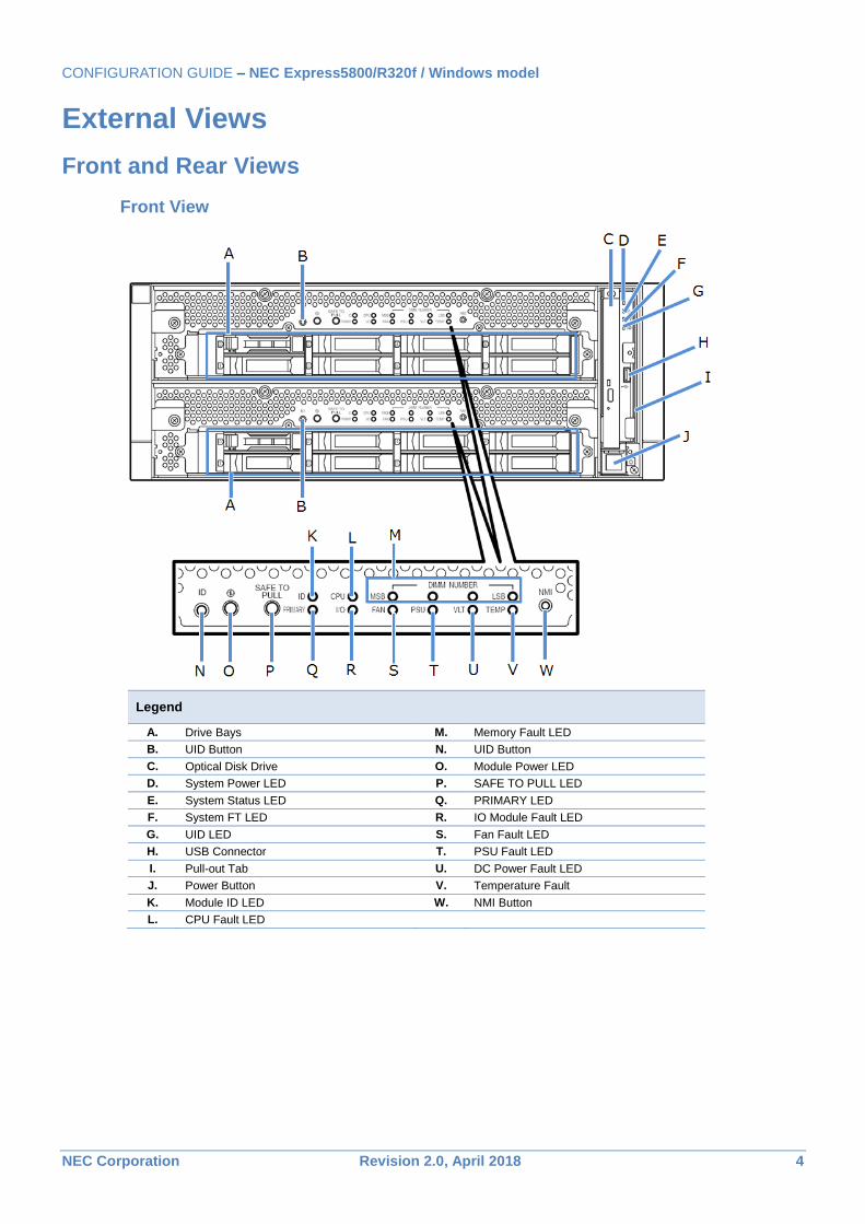
Front View
Legend
A. Drive Bays M. Memory Fault LED
B. UID Button N. UID Button C. Optical Disk Drive O. Module Power LED
D. System Power LED P. SAFE TO PULL LED
E. System Status LED Q. PRIMARY LED F. System FT LED R. IO Module Fault LED
G. UID LED S. Fan Fault LED
H. USB Connector T. PSU Fault LED
I. Pull-out Tab U. DC Power Fault LED
J. Power Button V. Temperature Fault
K. Module ID LED W. NMI Button
L. CPU Fault LED
CONFIGURATION GUIDE – NEC Express5800/R320f / Windows model
NEC Corporation Revision 2.0, April 2018 5
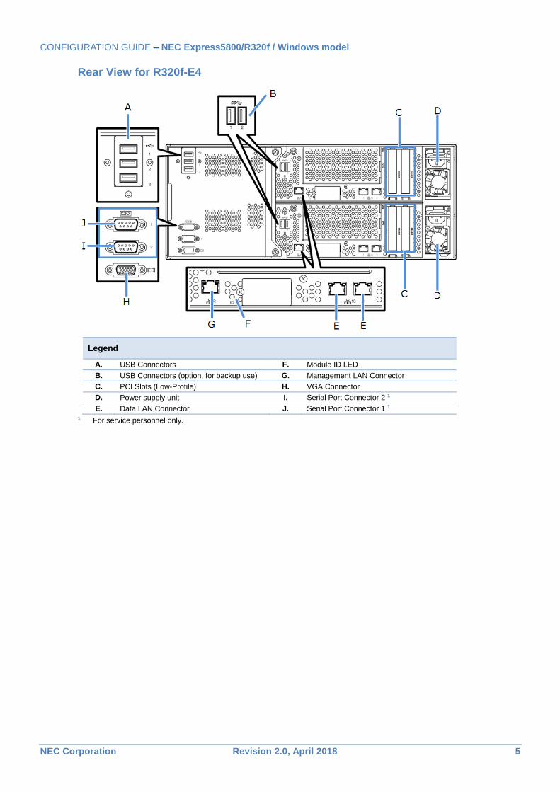
Rear View for R320f-E4
Legend
A. USB Connectors F. Module ID LED B. USB Connectors (option, for backup use) G. Management LAN Connector
C. PCI Slots (Low-Profile) H. VGA Connector
D. Power supply unit I. Serial Port Connector 2 1
E. Data LAN Connector J. Serial Port Connector 1 1
1 For service personnel only.
CONFIGURATION GUIDE – NEC Express5800/R320f / Windows model
NEC Corporation Revision 2.0, April 2018 6
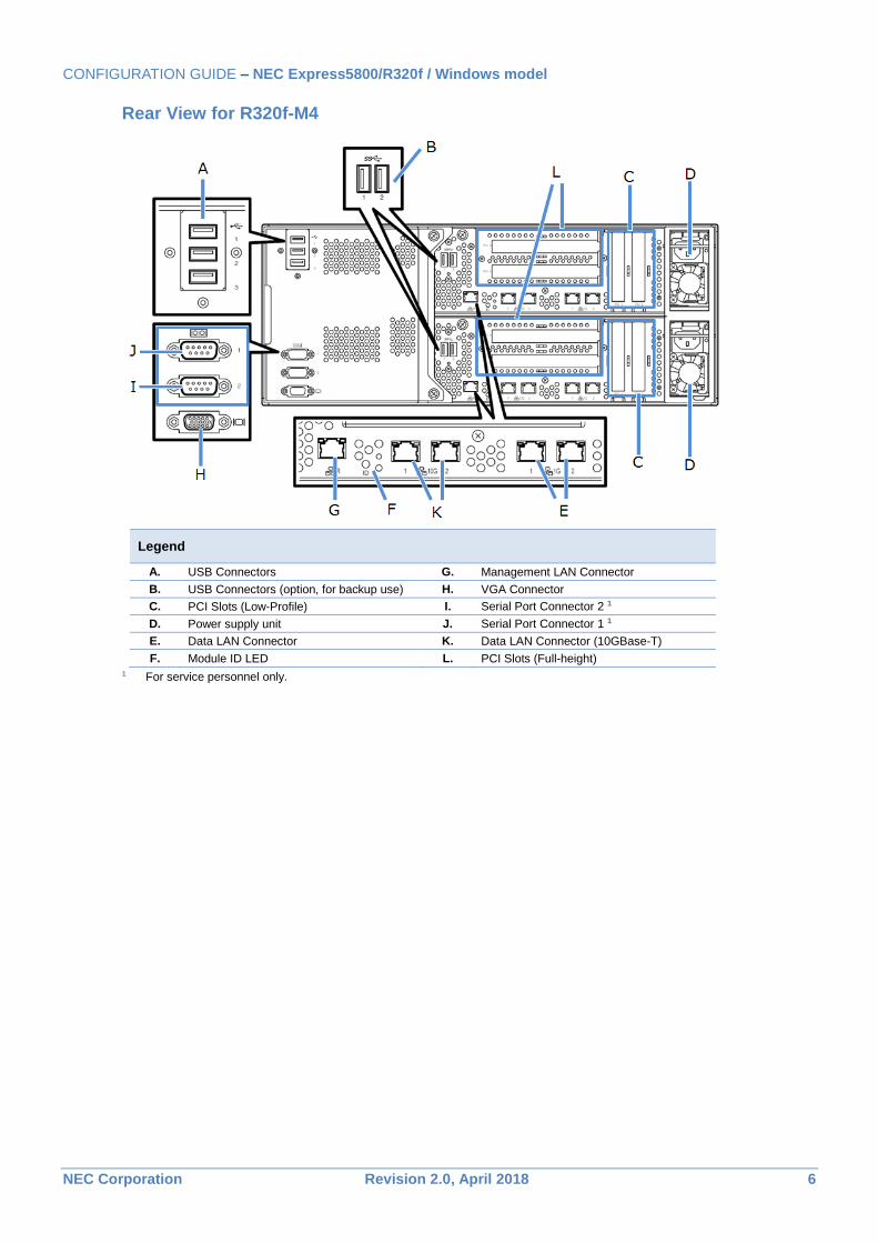
Rear View for R320f-M4
Legend
A. USB Connectors G. Management LAN Connector
B. USB Connectors (option, for backup use) H. VGA Connector
C. PCI Slots (Low-Profile) I. Serial Port Connector 2 1
D. Power supply unit J. Serial Port Connector 1 1
E. Data LAN Connector K. Data LAN Connector (10GBase-T)
F. Module ID LED L. PCI Slots (Full-height) 1 For service personnel only.
CONFIGURATION GUIDE – NEC Express5800/R320f / Windows model
NEC Corporation Revision 2.0, April 2018 7
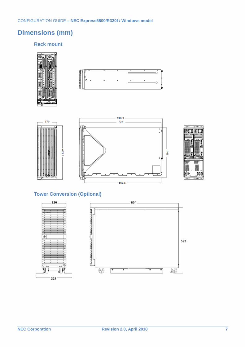
Dimensions (mm)
Rack mount
Tower Conversion (Optional)
220 804
592
327
CONFIGURATION GUIDE – NEC Express5800/R320f / Windows model
NEC Corporation Revision 2.0, April 2018 8
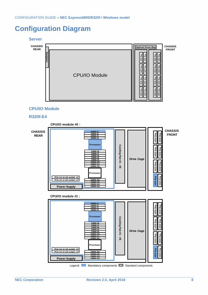
Configuration Diagram
Server
CPU/IO Module
R320f-E4
Legend: Mandatory components Standard components
Optical Drive Bay
HD
D B
ay
HD
D B
ay
HD
D B
ay
HD
D B
ay
HD
D B
ay
HD
D B
ay
HD
D B
ay
HD
D B
ay
HD
D B
ay
HD
D B
ay
HD
D B
ay
HD
D B
ay
HD
D B
ay
HD
D B
ay
HD
D B
ay
HD
D B
ay
CPU/IO Module
Backp
lan
e
CHASSIS
FRONT
CHASSIS
REAR
CPU/IO module #0 :
CPU/IO module #1 :
CHASSIS
FRONTCHASSIS
REAR
PCIe 3.0 x4 (x8 socket) LP
PCIe 3.0 x4 (x8 socket) LP
Drive Cage
Power Supply
Processor
DIMM #1DIMM #2DIMM #3DIMM #4
DIMM #8DIMM #7DIMM #6DIMM #5DIMM #9DIMM #10DIMM #11DIMM #12
DIMM #16
DIMM #15DIMM #14DIMM #13
Co
olin
g F
an
#1 -
#5
Processor
HD
D B
ay
HD
D B
ay
HD
D B
ay
HD
D B
ay
HD
D B
ay
HD
D B
ay
HD
D B
ay
HD
D B
ay
PCIe 3.0 x4 (x8 socket) LP
PCIe 3.0 x4 (x8 socket) LP
Drive Cage
Power Supply
Processor
DIMM #1DIMM #2DIMM #3DIMM #4
DIMM #8DIMM #7DIMM #6DIMM #5DIMM #9DIMM #10DIMM #11DIMM #12
DIMM #16DIMM #15DIMM #14DIMM #13
Co
olin
g F
an
#1 -
#5
Processor
HD
D B
ay
HD
D B
ay
HD
D B
ay
HD
D B
ay
HD
D B
ay
HD
D B
ay
HD
D B
ay
HD
D B
ay
CONFIGURATION GUIDE – NEC Express5800/R320f / Windows model
NEC Corporation Revision 2.0, April 2018 9
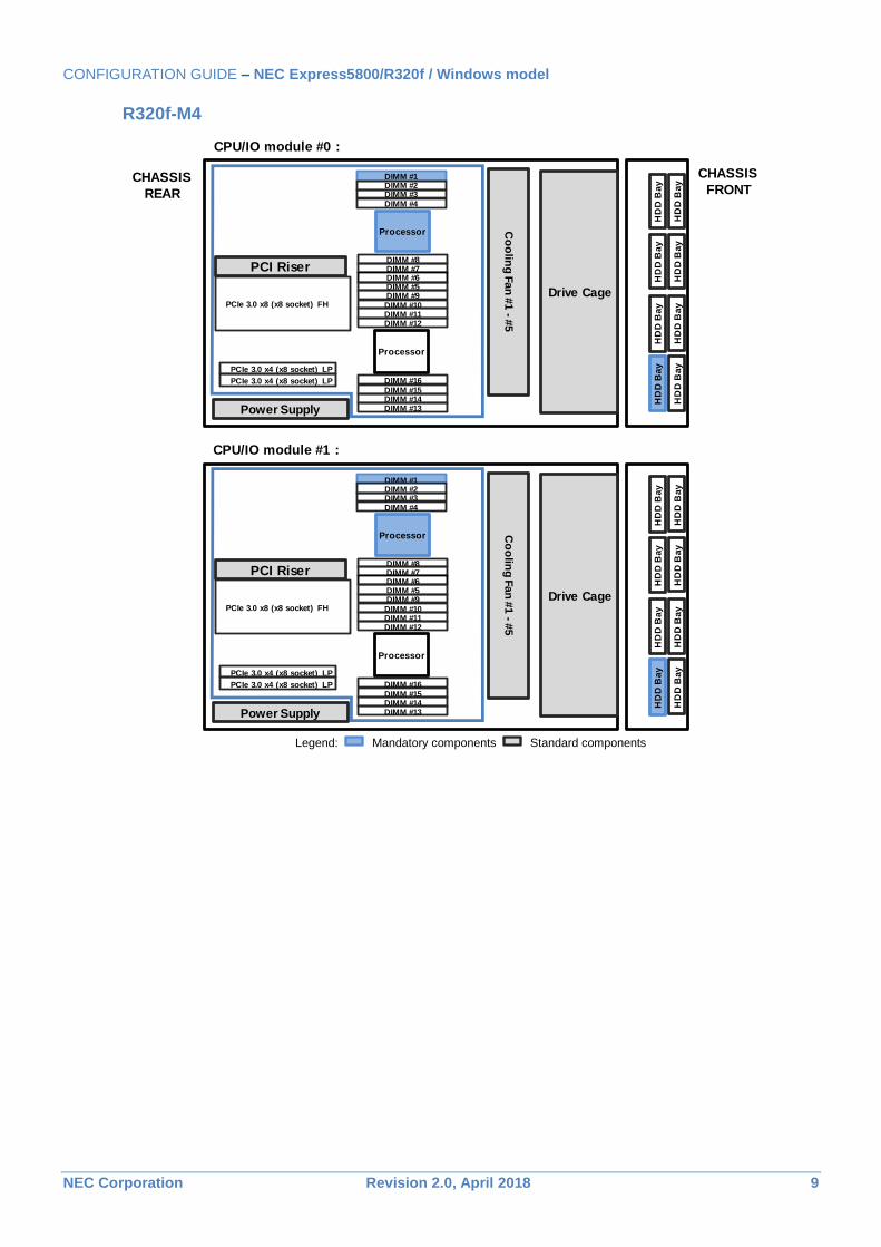
R320f-M4
Legend: Mandatory components Standard components
CPU/IO module #0 :
CPU/IO module #1 :
CHASSIS
FRONTCHASSIS
REAR
PCIe 3.0 x4 (x8 socket) LP
PCIe 3.0 x4 (x8 socket) LP
Drive Cage
Power Supply
Processor
DIMM #1DIMM #2DIMM #3DIMM #4
DIMM #8DIMM #7DIMM #6DIMM #5DIMM #9DIMM #10DIMM #11DIMM #12
DIMM #16
DIMM #15DIMM #14DIMM #13
Co
olin
g F
an
#1 -
#5
Processor
PCI Riser
PCIe 3.0 x8 (x8 socket) FH
HD
D B
ay
HD
D B
ay
HD
D B
ay
HD
D B
ay
HD
D B
ay
HD
D B
ay
HD
D B
ay
HD
D B
ay
PCIe 3.0 x4 (x8 socket) LP
PCIe 3.0 x4 (x8 socket) LP
Drive Cage
Power Supply
Processor
DIMM #1DIMM #2DIMM #3DIMM #4
DIMM #8DIMM #7DIMM #6DIMM #5DIMM #9DIMM #10DIMM #11DIMM #12
DIMM #16DIMM #15DIMM #14DIMM #13
Co
olin
g F
an
#1 -
#5
Processor
PCI Riser
PCIe 3.0 x8 (x8 socket) FH
HD
D B
ay
HD
D B
ay
HD
D B
ay
HD
D B
ay
HD
D B
ay
HD
D B
ay
HD
D B
ay
HD
D B
ay
CONFIGURATION GUIDE – NEC Express5800/R320f / Windows model
NEC Corporation Revision 2.0, April 2018 10
Server Configuration
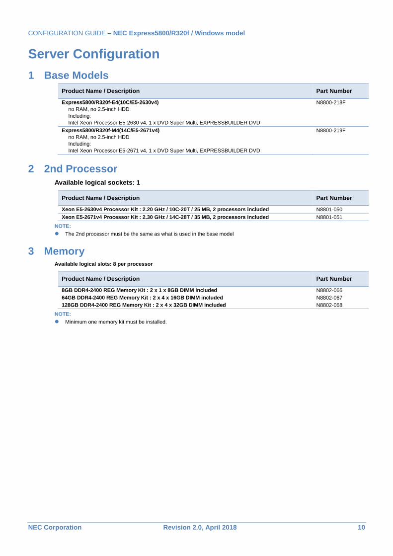
1 Base Models
Product Name / Description Part Number
Express5800/R320f-E4(10C/E5-2630v4)
no RAM, no 2.5-inch HDD
Including:
Intel Xeon Processor E5-2630 v4, 1 x DVD Super Multi, EXPRESSBUILDER DVD
N8800-218F
Express5800/R320f-M4(14C/E5-2671v4)
no RAM, no 2.5-inch HDD
Including:
Intel Xeon Processor E5-2671 v4, 1 x DVD Super Multi, EXPRESSBUILDER DVD
N8800-219F
2 2nd Processor
Available logical sockets: 1
Product Name / Description Part Number
Xeon E5-2630v4 Processor Kit : 2.20 GHz / 10C-20T / 25 MB, 2 processors included N8801-050
Xeon E5-2671v4 Processor Kit : 2.30 GHz / 14C-28T / 35 MB, 2 processors included N8801-051
NOTE:
The 2nd processor must be the same as what is used in the base model
3 Memory Available logical slots: 8 per processor
Product Name / Description Part Number
8GB DDR4-2400 REG Memory Kit : 2 x 1 x 8GB DIMM included N8802-066
64GB DDR4-2400 REG Memory Kit : 2 x 4 x 16GB DIMM included N8802-067
128GB DDR4-2400 REG Memory Kit : 2 x 4 x 32GB DIMM included N8802-068
NOTE:
Minimum one memory kit must be installed.
CONFIGURATION GUIDE – NEC Express5800/R320f / Windows model
NEC Corporation Revision 2.0, April 2018 11
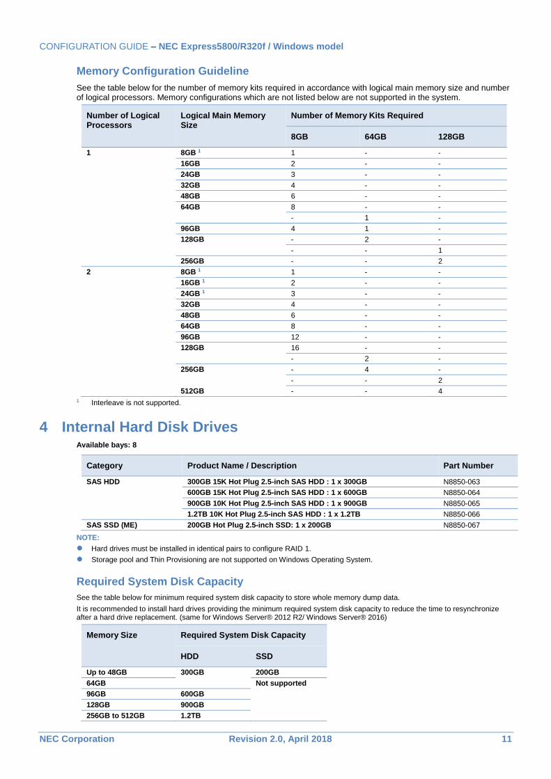
Memory Configuration Guideline
See the table below for the number of memory kits required in accordance with logical main memory size and number of logical processors. Memory configurations which are not listed below are not supported in the system.
Number of Logical Processors
Logical Main Memory Size
Number of Memory Kits Required
8GB 64GB 128GB
1 8GB 1 1 - -
16GB 2 - -
24GB 3 - -
32GB 4 - -
48GB 6 - -
64GB 8 - -
- 1 -
96GB 4 1 -
128GB - 2 -
- - 1
256GB - - 2
2 8GB 1 1 - -
16GB 1 2 - -
24GB 1 3 - -
32GB 4 - -
48GB 6 - -
64GB 8 - -
96GB 12 - -
128GB 16 - -
- 2 -
256GB - 4 -
- - 2
512GB - - 4
1 Interleave is not supported.
4 Internal Hard Disk Drives Available bays: 8
Category Product Name / Description Part Number
SAS HDD 300GB 15K Hot Plug 2.5-inch SAS HDD : 1 x 300GB N8850-063
600GB 15K Hot Plug 2.5-inch SAS HDD : 1 x 600GB N8850-064
900GB 10K Hot Plug 2.5-inch SAS HDD : 1 x 900GB N8850-065
1.2TB 10K Hot Plug 2.5-inch SAS HDD : 1 x 1.2TB N8850-066
SAS SSD (ME) 200GB Hot Plug 2.5-inch SSD: 1 x 200GB N8850-067
NOTE:
Hard drives must be installed in identical pairs to configure RAID 1.
Storage pool and Thin Provisioning are not supported on Windows Operating System.
Required System Disk Capacity
See the table below for minimum required system disk capacity to store whole memory dump data.
It is recommended to install hard drives providing the minimum required system disk capacity to reduce the time to resynchronize after a hard drive replacement. (same for Windows Server® 2012 R2/ Windows Server® 2016)
Memory Size Required System Disk Capacity
HDD SSD
Up to 48GB 300GB 200GB
64GB Not supported
96GB 600GB
128GB 900GB
256GB to 512GB 1.2TB
CONFIGURATION GUIDE – NEC Express5800/R320f / Windows model
NEC Corporation Revision 2.0, April 2018 12
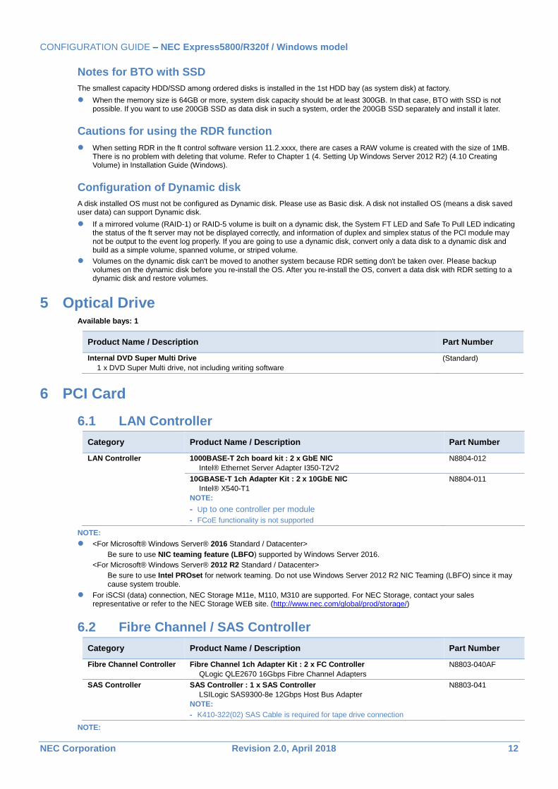
Notes for BTO with SSD
The smallest capacity HDD/SSD among ordered disks is installed in the 1st HDD bay (as system disk) at factory.
When the memory size is 64GB or more, system disk capacity should be at least 300GB. In that case, BTO with SSD is not possible. If you want to use 200GB SSD as data disk in such a system, order the 200GB SSD separately and install it later.
Cautions for using the RDR function
When setting RDR in the ft control software version 11.2.xxxx, there are cases a RAW volume is created with the size of 1MB. There is no problem with deleting that volume. Refer to Chapter 1 (4. Setting Up Windows Server 2012 R2) (4.10 Creating Volume) in Installation Guide (Windows).
Configuration of Dynamic disk
A disk installed OS must not be configured as Dynamic disk. Please use as Basic disk. A disk not installed OS (means a disk saved user data) can support Dynamic disk.
If a mirrored volume (RAID-1) or RAID-5 volume is built on a dynamic disk, the System FT LED and Safe To Pull LED indicating the status of the ft server may not be displayed correctly, and information of duplex and simplex status of the PCI module may not be output to the event log properly. If you are going to use a dynamic disk, convert only a data disk to a dynamic disk and build as a simple volume, spanned volume, or striped volume.
Volumes on the dynamic disk can't be moved to another system because RDR setting don't be taken over. Please backup volumes on the dynamic disk before you re-install the OS. After you re-install the OS, convert a data disk with RDR setting to a dynamic disk and restore volumes.
5 Optical Drive Available bays: 1
Product Name / Description Part Number
Internal DVD Super Multi Drive
1 x DVD Super Multi drive, not including writing software
(Standard)
6 PCI Card
6.1 LAN Controller
Category Product Name / Description Part Number
LAN Controller 1000BASE-T 2ch board kit : 2 x GbE NIC
Intel® Ethernet Server Adapter I350-T2V2
N8804-012
10GBASE-T 1ch Adapter Kit : 2 x 10GbE NIC
Intel® X540-T1
NOTE:
- Up to one controller per module
- FCoE functionality is not supported
N8804-011
NOTE:
<For Microsoft® Windows Server® 2016 Standard / Datacenter>
Be sure to use NIC teaming feature (LBFO) supported by Windows Server 2016.
<For Microsoft® Windows Server® 2012 R2 Standard / Datacenter>
Be sure to use Intel PROset for network teaming. Do not use Windows Server 2012 R2 NIC Teaming (LBFO) since it may cause system trouble.
For iSCSI (data) connection, NEC Storage M11e, M110, M310 are supported. For NEC Storage, contact your sales representative or refer to the NEC Storage WEB site. (http://www.nec.com/global/prod/storage/)
6.2 Fibre Channel / SAS Controller
Category Product Name / Description Part Number
Fibre Channel Controller Fibre Channel 1ch Adapter Kit : 2 x FC Controller
QLogic QLE2670 16Gbps Fibre Channel Adapters
N8803-040AF
SAS Controller SAS Controller : 1 x SAS Controller
LSILogic SAS9300-8e 12Gbps Host Bus Adapter
NOTE:
- K410-322(02) SAS Cable is required for tape drive connection
N8803-041
NOTE:

CONFIGURATION GUIDE – NEC Express5800/R320f / Windows model
NEC Corporation Revision 2.0, April 2018 13
For supported NEC Storage products to connect with N8803-040F, contact your sales representative or refer to the NEC Storage WEB site. (http://www.nec.com/global/prod/storage/)
CONFIGURATION GUIDE – NEC Express5800/R320f / Windows model
NEC Corporation Revision 2.0, April 2018 14
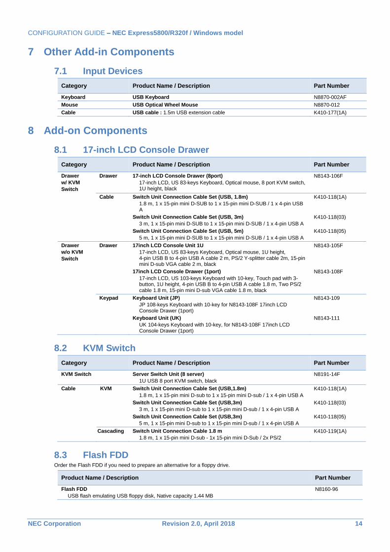
7 Other Add-in Components
7.1 Input Devices
Category Product Name / Description Part Number
Keyboard USB Keyboard N8870-002AF
Mouse USB Optical Wheel Mouse N8870-012
Cable USB cable : 1.5m USB extension cable K410-177(1A)
8 Add-on Components
8.1 17-inch LCD Console Drawer
Category Product Name / Description Part Number
Drawer
w/ KVM
Switch
Drawer 17-inch LCD Console Drawer (8port)
17-inch LCD, US 83-keys Keyboard, Optical mouse, 8 port KVM switch, 1U height, black
N8143-106F
Cable Switch Unit Connection Cable Set (USB, 1.8m)
1.8 m, 1 x 15-pin mini D-SUB to 1 x 15-pin mini D-SUB / 1 x 4-pin USB A
K410-118(1A)
Switch Unit Connection Cable Set (USB, 3m)
3 m, 1 x 15-pin mini D-SUB to 1 x 15-pin mini D-SUB / 1 x 4-pin USB A
K410-118(03)
Switch Unit Connection Cable Set (USB, 5m)
5 m, 1 x 15-pin mini D-SUB to 1 x 15-pin mini D-SUB / 1 x 4-pin USB A
K410-118(05)
Drawer
w/o KVM
Switch
Drawer 17inch LCD Console Unit 1U
17-inch LCD, US 83-keys Keyboard, Optical mouse, 1U height, 4-pin USB B to 4-pin USB A cable 2 m, PS/2 Y-splitter cable 2m, 15-pin mini D-sub VGA cable 2 m, black
N8143-105F
17inch LCD Console Drawer (1port)
17-inch LCD, US 103-keys Keyboard with 10-key, Touch pad with 3-button, 1U height, 4-pin USB B to 4-pin USB A cable 1.8 m, Two PS/2 cable 1.8 m, 15-pin mini D-sub VGA cable 1.8 m, black
N8143-108F
Keypad Keyboard Unit (JP)
JP 108-keys Keyboard with 10-key for N8143-108F 17inch LCD Console Drawer (1port)
N8143-109
Keyboard Unit (UK)
UK 104-keys Keyboard with 10-key, for N8143-108F 17inch LCD Console Drawer (1port)
N8143-111
8.2 KVM Switch
Category Product Name / Description Part Number
KVM Switch Server Switch Unit (8 server)
1U USB 8 port KVM switch, black
N8191-14F
Cable KVM Switch Unit Connection Cable Set (USB,1.8m)
1.8 m, 1 x 15-pin mini D-sub to 1 x 15-pin mini D-sub / 1 x 4-pin USB A
K410-118(1A)
Switch Unit Connection Cable Set (USB,3m)
3 m, 1 x 15-pin mini D-sub to 1 x 15-pin mini D-sub / 1 x 4-pin USB A
K410-118(03)
Switch Unit Connection Cable Set (USB,3m)
5 m, 1 x 15-pin mini D-sub to 1 x 15-pin mini D-sub / 1 x 4-pin USB A
K410-118(05)
Cascading Switch Unit Connection Cable 1.8 m
1.8 m, 1 x 15-pin mini D-sub - 1x 15-pin mini D-Sub / 2x PS/2
K410-119(1A)
8.3 Flash FDD Order the Flash FDD if you need to prepare an alternative for a floppy drive.
Product Name / Description Part Number
Flash FDD
USB flash emulating USB floppy disk, Native capacity 1.44 MB
N8160-96
CONFIGURATION GUIDE – NEC Express5800/R320f / Windows model
NEC Corporation Revision 2.0, April 2018 15
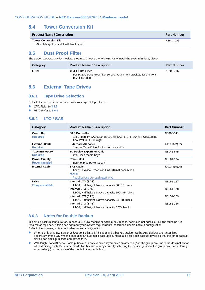
8.4 Tower Conversion Kit
Product Name / Description Part Number
Tower Conversion Kit
23 inch height pedestal with front bezel
N8843-005
8.5 Dust Proof Filter The server supports the dust resistant feature. Choose the following kit to install the system in dusty places.
Category Product Name / Description Part Number
Filter 4U-FT Dust Filter
For R320e Dust Proof filter 10 pcs, attachment brackets for the front bezel included
N8847-002
8.6 External Tape Drives
8.6.1 Tape Drive Selection
Refer to the section in accordance with your type of tape drives.
LTO: Refer to 8.6.2
RDX: Refer to 8.6.5
8.6.2 LTO / SAS
Category Product Name / Description Part Number
Controller
Required
SAS Controller
1 x Broadcom SAS9300-8e 12Gb/s SAS, 8(SFF-8644), PCIe3.0(x8), Low Profile / Full Height
N8803-041
External Cable
Required
External SAS cable
2 m, for Tape Drive Enclosure connection
K410-322(02)
Tape Enclosure
Required
1U Device Expansion Unit
2 x 5-inch media bays
N8141-69F
Power Supply
Recommended
Power Unit
non-hot plug power supply
N8181-124F
Internal Cable
SAS Cable
For 1U Device Expansion Unit internal connection
NOTE:
- Required one per each tape drive.
K410-335(00)
Drive
2 bays available
Internal LTO (SAS)
LTO4, Half height, Native capacity 800GB, black
N8151-127
Internal LTO (SAS)
LTO5, Half height, Native capacity 1500GB, black
N8151-128
Internal LTO (SAS)
LTO6, Half height, Native capacity 2.5 TB, black
N8151-129
Internal LTO (SAS)
LTO7, Half height, Native capacity 6 TB, black
N8151-136
8.6.3 Notes for Double Backup
In a single backup configuration, in case a CPU/IO module or backup device fails, backup is not possible until the failed part is repaired or replaced. If this does not meet your system requirements, consider a double backup configuration. Refer to the following notes on double backup configuration.
When configuring two sets of a SAS controller, a SAS cable and a backup device, two backup devices are recognized separately by the OS. When scheduling an automatic backup job, make a job for each backup device so that the other backup device can backup in case one device fails.
With BrightStor ARCserve Backup, backup is not executed if you enter an asterisk (*) in the group box under the destination tab when defining a job. Be sure to create two backup jobs by correctly selecting the device group for the group box, and entering an asterisk (*) or the name of the media in the media box.
CONFIGURATION GUIDE – NEC Express5800/R320f / Windows model
NEC Corporation Revision 2.0, April 2018 16
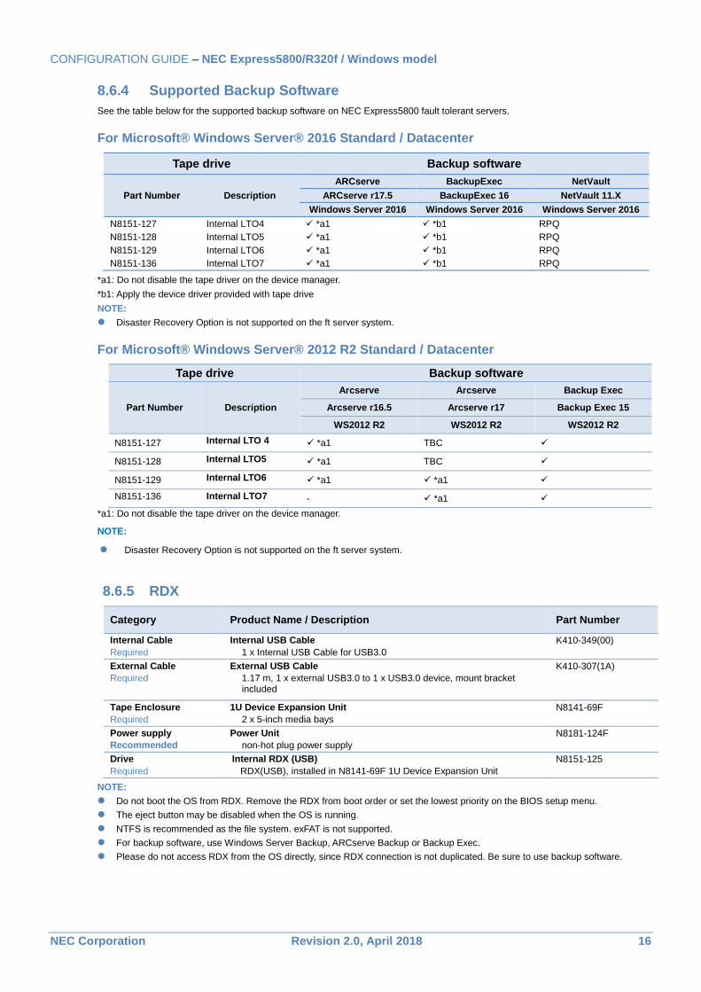
8.6.4 Supported Backup Software
See the table below for the supported backup software on NEC Express5800 fault tolerant servers.
For Microsoft® Windows Server® 2016 Standard / Datacenter
Tape drive Backup software
Part Number Description
ARCserve BackupExec NetVault
ARCserve r17.5 BackupExec 16 NetVault 11.X
Windows Server 2016 Windows Server 2016 Windows Server 2016
N8151-127 Internal LTO4 *a1 *b1 RPQ
N8151-128 Internal LTO5 *a1 *b1 RPQ
N8151-129 Internal LTO6 *a1 *b1 RPQ
N8151-136 Internal LTO7 *a1 *b1 RPQ
*a1: Do not disable the tape driver on the device manager.
*b1: Apply the device driver provided with tape drive
NOTE:
Disaster Recovery Option is not supported on the ft server system.
For Microsoft® Windows Server® 2012 R2 Standard / Datacenter
Tape drive Backup software
Part Number Description
Arcserve Arcserve Backup Exec
Arcserve r16.5 Arcserve r17 Backup Exec 15
WS2012 R2 WS2012 R2 WS2012 R2
N8151-127 Internal LTO 4 *a1 TBC
N8151-128 Internal LTO5 *a1 TBC
N8151-129 Internal LTO6 *a1 *a1
N8151-136 Internal LTO7 - *a1
*a1: Do not disable the tape driver on the device manager.
NOTE:
Disaster Recovery Option is not supported on the ft server system.
8.6.5 RDX
Category Product Name / Description Part Number
Internal Cable
Required
Internal USB Cable
1 x Internal USB Cable for USB3.0
K410-349(00)
External Cable
Required
External USB Cable
1.17 m, 1 x external USB3.0 to 1 x USB3.0 device, mount bracket included
K410-307(1A)
Tape Enclosure
Required
1U Device Expansion Unit
2 x 5-inch media bays
N8141-69F
Power supply
Recommended
Power Unit
non-hot plug power supply
N8181-124F
Drive
Required
Internal RDX (USB)
RDX(USB), installed in N8141-69F 1U Device Expansion Unit
N8151-125
NOTE:
Do not boot the OS from RDX. Remove the RDX from boot order or set the lowest priority on the BIOS setup menu.
The eject button may be disabled when the OS is running.
NTFS is recommended as the file system. exFAT is not supported.
For backup software, use Windows Server Backup, ARCserve Backup or Backup Exec.
Please do not access RDX from the OS directly, since RDX connection is not duplicated. Be sure to use backup software.
CONFIGURATION GUIDE – NEC Express5800/R320f / Windows model
NEC Corporation Revision 2.0, April 2018 17
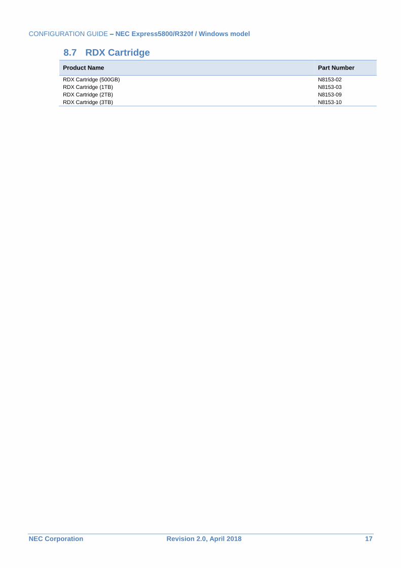
8.7 RDX Cartridge
Product Name Part Number
RDX Cartridge (500GB) N8153-02
RDX Cartridge (1TB) N8153-03
RDX Cartridge (2TB) N8153-09
RDX Cartridge (3TB) N8153-10
CONFIGURATION GUIDE – NEC Express5800/R320f / Windows model
NEC Corporation Revision 2.0, April 2018 18
References
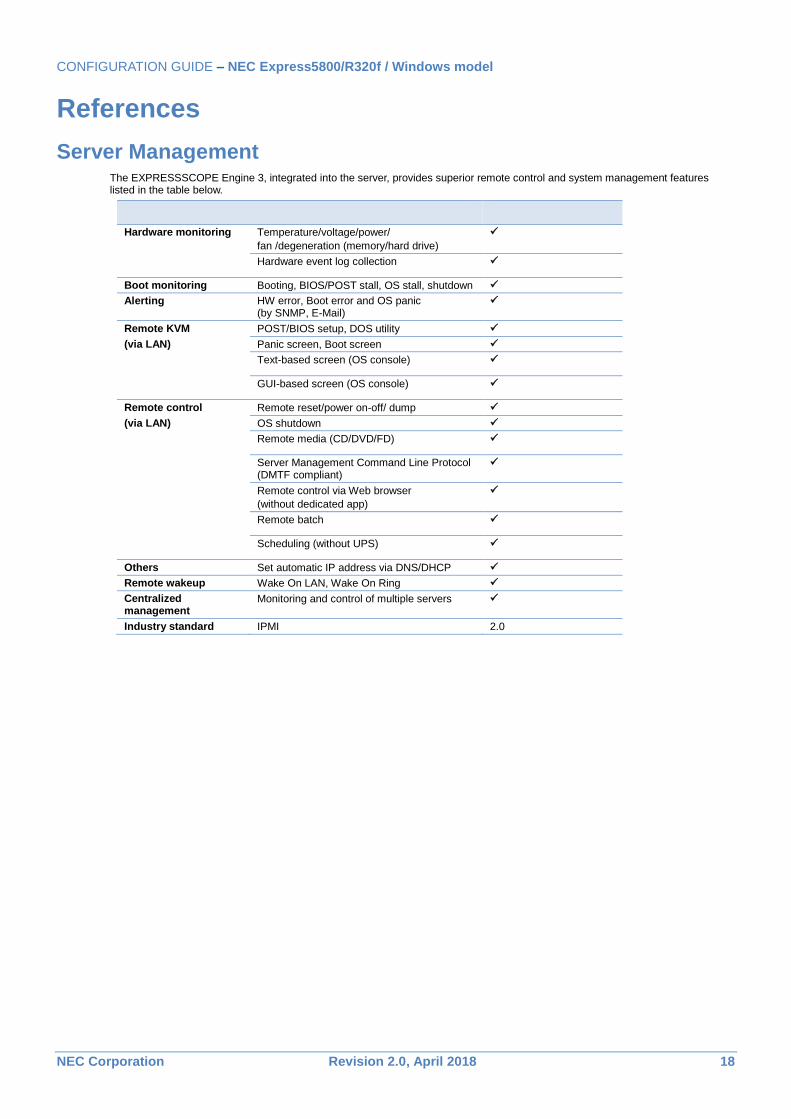
Server Management The EXPRESSSCOPE Engine 3, integrated into the server, provides superior remote control and system management features listed in the table below.
Hardware monitoring Temperature/voltage/power/
fan /degeneration (memory/hard drive)
Hardware event log collection
Boot monitoring Booting, BIOS/POST stall, OS stall, shutdown
Alerting HW error, Boot error and OS panic (by SNMP, E-Mail)
Remote KVM POST/BIOS setup, DOS utility
(via LAN) Panic screen, Boot screen
Text-based screen (OS console)
GUI-based screen (OS console)
Remote control Remote reset/power on-off/ dump
(via LAN) OS shutdown
Remote media (CD/DVD/FD)
Server Management Command Line Protocol (DMTF compliant)
Remote control via Web browser
(without dedicated app)
Remote batch
Scheduling (without UPS)
Others Set automatic IP address via DNS/DHCP
Remote wakeup Wake On LAN, Wake On Ring
Centralized management
Monitoring and control of multiple servers
Industry standard IPMI 2.0
CONFIGURATION GUIDE – NEC Express5800/R320f / Windows model
NEC Corporation Revision 2.0, April 2018 19
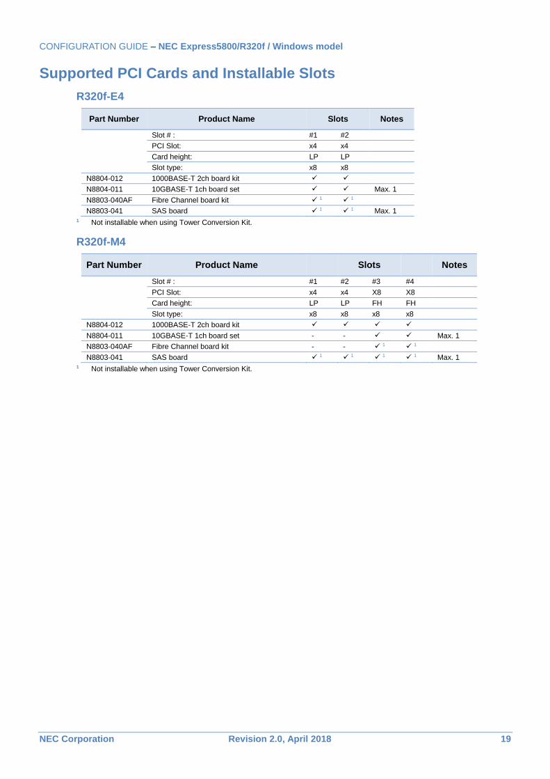
Supported PCI Cards and Installable Slots
R320f-E4
Part Number Product Name Slots Notes
Slot # : #1 #2
PCI Slot: x4 x4
Card height: LP LP
Slot type: x8 x8
N8804-012 1000BASE-T 2ch board kit
N8804-011 10GBASE-T 1ch board set Max. 1
N8803-040AF Fibre Channel board kit 1 1
N8803-041 SAS board 1 1 Max. 1
1 Not installable when using Tower Conversion Kit.
R320f-M4
Part Number Product Name Slots Notes
Slot # : #1 #2 #3 #4
PCI Slot: x4 x4 X8 X8
Card height: LP LP FH FH
Slot type: x8 x8 x8 x8
N8804-012 1000BASE-T 2ch board kit
N8804-011 10GBASE-T 1ch board set - - Max. 1
N8803-040AF Fibre Channel board kit - - 1 1
N8803-041 SAS board 1 1 1 1 Max. 1 1 Not installable when using Tower Conversion Kit.
CONFIGURATION GUIDE – NEC Express5800/R320f / Windows model
NEC Corporation Revision 2.0, April 2018 20
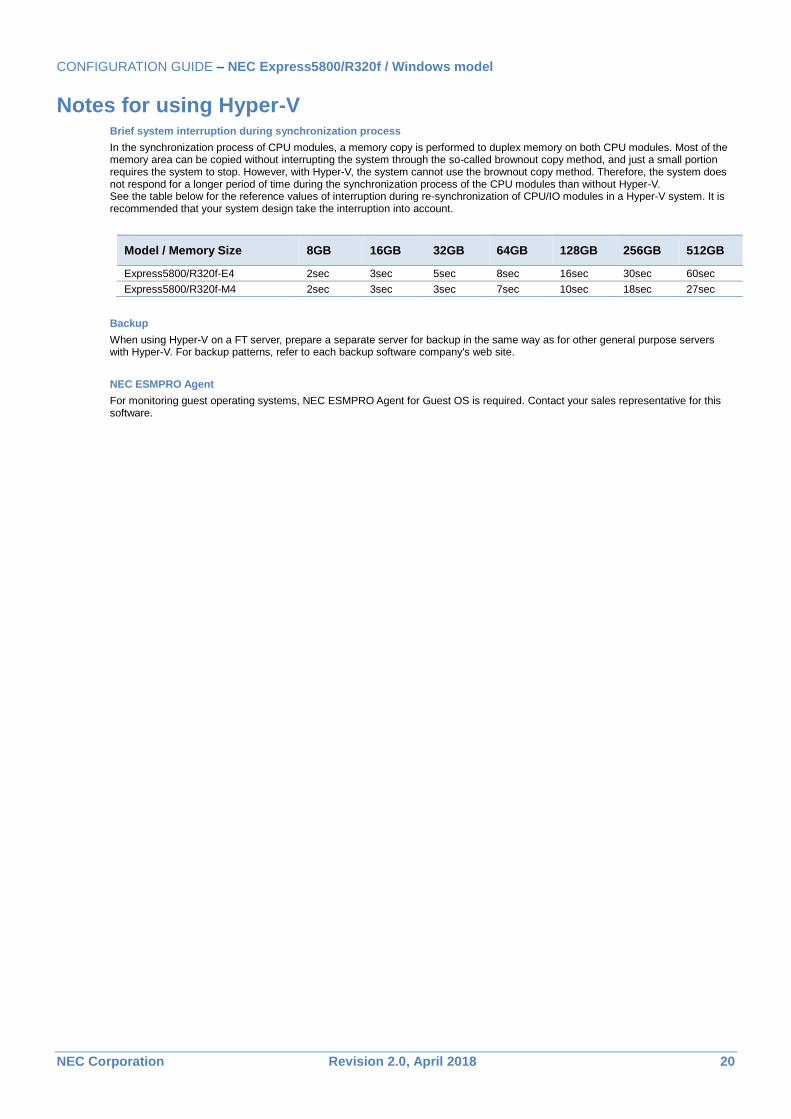
Notes for using Hyper-V Brief system interruption during synchronization process
In the synchronization process of CPU modules, a memory copy is performed to duplex memory on both CPU modules. Most of the memory area can be copied without interrupting the system through the so-called brownout copy method, and just a small portion requires the system to stop. However, with Hyper-V, the system cannot use the brownout copy method. Therefore, the system does not respond for a longer period of time during the synchronization process of the CPU modules than without Hyper-V. See the table below for the reference values of interruption during re-synchronization of CPU/IO modules in a Hyper-V system. It is recommended that your system design take the interruption into account.
Model / Memory Size 8GB 16GB 32GB 64GB 128GB 256GB 512GB
Express5800/R320f-E4 2sec 3sec 5sec 8sec 16sec 30sec 60sec
Express5800/R320f-M4 2sec 3sec 3sec 7sec 10sec 18sec 27sec
Backup
When using Hyper-V on a FT server, prepare a separate server for backup in the same way as for other general purpose servers with Hyper-V. For backup patterns, refer to each backup software company's web site.
NEC ESMPRO Agent
For monitoring guest operating systems, NEC ESMPRO Agent for Guest OS is required. Contact your sales representative for this software.
CONFIGURATION GUIDE – NEC Express5800/R320f / Windows model
NEC Corporation Revision 2.0, April 2018 21
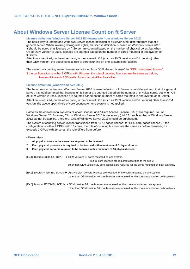
About Windows Server License Count on ft Server License definition (Windows Server 2012 R2 downgrade from Windows Server 2016)
The basic way to understand Windows Server license definition of ft Server is not different from that of a general server. When invoking downgrade rights, the license definition is based on Windows Server 2016. It should be noted that licenses on ft Server are counted based on the number of physical cores, but when OS of OEM version is used, licenses are counted based on the number of cores mounted in one system on ft Server. Attention is required, on the other hand, in the case with OS (such as PKG version and VL version) other than OEM version, the above special rule of core counting on one system is not applied. ---
The system of counting server license transitioned from “CPU-based license” to ”CPU core-based license”.
If the configuration is within 2 CPUs with 16 cores, the rule of counting licenses are the same as before,
however, if it exceeds 2 CPUs with 16 cores, the rule differs from before.
License definition (Windows Server 2016)
The basic way to understand Windows Server 2016 license definition of ft Server is not different from that of a general server. It should be noted that licenses on ft Server are counted based on the number of physical cores, but when OS of OEM version is used, licenses are counted based on the number of cores mounted in one system on ft Server.
Attention is required, on the other hand, in the case with OS (such as PKG version and VL version) other than OEM version, the above special rule of core counting on one system is not applied.
---
Same as the conventional systems, “Server License” and “Client Access License (CAL)” are required. To use Windows Server 2016 server, CAL of Windows Server 2016 is necessary (old CAL such as that of Windows Server 2012 cannot be applied, therefore, CAL of Windows Server 2016 should be purchased).
The system of counting server license transitioned from “CPU-based license” to ”CPU core-based license”. If the configuration is within 2 CPUs with 16 cores, the rule of counting licenses are the same as before, however, if it exceeds 2 CPUs with 16 cores, the rule differs from before.
<Three rules>
1. All physical cores in the server are required to be licensed.
2. Each physical processor is required to be licensed with a minimum of 8 physical cores.
3. Each physical server is required to be licensed with a minimum of 16 physical cores.
[Ex.1] 10cores R320f-E4, 1CPU OEM version: 10 cores mounted on one system,
but 16 core licenses are required according to the rule 3.
other than OEM version: 20 core licenses are required for the cores mounted on both systems.
[Ex.2] 10cores R320f-E4, 2CPUs OEM version: 20 core licenses are required for the cores mounted on one system.
other than OEM version: 40 core licenses are required for the cores mounted on both systems.
[Ex.3] 14 cores R320f-M4, 2CPUs OEM version: 28 core licenses are required for the cores mounted on one system.
other than OEM version: 56 core licenses are required for the cores mounted on both systems.
CONFIGURATION GUIDE – NEC Express5800/R320f / Windows model
NEC Corporation Revision 2.0, April 2018 22
Copyright Notice and Liability Disclaimer The information contained herein is subject to change without notice.
Microsoft and Windows Server are either registered trademarks or trademarks of Microsoft Corporation in the United States and/or other countries
Intel and Xeon are registered trademarks or trademarks of Intel Corporation or its subsidiaries in the United States and other countries.
Linux is a trademark of Linus Torvalds.
Red Hat is a registered trademark of Red Hat, Inc. in the U.S.
All other products, brands, or trade names used in this document are trademarks or registered trademarks of their respective holders.
NEC shall not be liable for technical or editorial errors or omissions contained herein.
For hard drive capacity measurements, 1 GB = 1 billion bytes. Actual formatted capacity is less.
CONFIGURATION GUIDE – NEC Express5800/R320f / Windows model
NEC Corporation Revision 2.0, April 2018 23
Revision History
Revision Date Description
2.0 April 20, 2018 Windows server 2012 R2 support
1.0 August 8, 2017 Initial release