near-net-shape production of hollow titanium alloy ... · near-net-shape production of hollow...
TRANSCRIPT
Near-Net-Shape Production of Hollow Titanium AlloyComponents via Electrochemical Reduction of MetalOxide Precursors in Molten Salts
DI HU, WEI XIAO, and GEORGE Z. CHEN
Metal oxide precursors (ca. 90 wt pct Ti, 6 wt pct Al, and 4 wt pct V) were prepared with ahollow structure in various shapes such as a sphere, miniature golf club head, and cup using aone-step solid slip-casting process. The precursors were then electro-deoxidized in molten cal-cium chloride [3.2 V, 1173 K (900 �C)] against a graphite anode. After 24 hours of electrolysis,the near-net-shape Ti-6Al-4V product maintained its original shape with controlled shrinkage.Oxygen contents in the Ti-6Al-4V components were typically below 2000 ppm. The maximumcompressive stress and modulus of electrolytic products obtained in this work were approxi-mately 243 MPa and 14 GPa, respectively, matching with the requirement for medical implants.Further research directions are discussed for mechanical improvement of the products viadensification during or after electrolysis. This simple, fast, and energy-efficient near-net-shapemanufacturing method could allow titanium alloy components with desired geometries to beprepared directly from a mixture of metal oxides, promising an innovative technology for thelow-cost production of titanium alloy components.
DOI: 10.1007/s11663-013-9800-5� The Author(s) 2013. This article is published with open access at Springerlink.com
I. INTRODUCTION
TITANIUM metal and its alloys exhibit high specificstrength, light weight, outstanding biocompatibility, andexcellent corrosion resistance.[1,2] However, due to theinherent costliness, they are seriously restricted tocritical and demanding niche applications,[3] such asthe aeroplanes,[4] medical implants,[5] and performance-improving sports equipment.[6] Broadly speaking, thehigh cost of titanium and its alloys arises from twofactors: the energy- and labor-intensive extraction oftitanium metal (sponge) via the Kroll Process[7] (6 to 29$/kg depending on demand) and the complex andexpensive downstream processes for alloying and man-ufacturing of the final components (10 to 30 times of thesponge value).[8]
The cost of the post-extraction alloying processes issignificant, because the wide differences in the meltingpoints and densities of the alloying elements necessitatemultiple remelting steps to insure homogeneity of thefinal alloys. Furthermore, due to the high affinity tooxygen and the poor workability of titanium and its
alloys, the downstream shaping processes are also besetwith difficulties, which drastically increase the cost of thefinal components.[2] For instance, the cost of down-stream processes for the production of a 2.54-cm-thicktitanium alloy plate accounts for 62 pct of the totalcost;[8] fabrication of more complex shapes is of coursemore expensive, constituting a commensurately greaterproportion of the bottom-line figure. Consequently, inrecent years, the primary focus in titanium technologydevelopment has been the production of cost-affordabletitanium and titanium alloy components rather than thedevelopment of new alloys with enhanced properties.[9]
The results are two research routes: devising novelmethods for the extraction of titanium metal anddeveloping creative techniques for the fabrication oftitanium and its alloy components.Over the last two decades, there have been approx-
imately 20 newly proposed processes, some of which arebeing commercially developed, directed toward the low-cost extraction of titanium coupled with optimization ofexisting processes.[8,10] A majority of these developmentsfocus on the production of commercially pure titanium,with few having the capability to produce titaniumalloys directly and fewer still having done so. Notableamong these, the FFC-Cambridge Process[11] has beensuccessfully demonstrated to directly produce titaniummetal and its alloys[12] by the electrochemical reductionof a cathodic oxide precursor in a molten salt electrolyte.During this process, the ionized oxygen atoms aretransferred via the molten salt from the cathode to theanode where they discharge as CO/CO2 or O2 forgraphite or inert anode materials, respectively. TheFFC-Cambridge Process is capable of producing com-mercially pure titanium sponge (<2000 ppm O) at an
DI HU, Postdoctoral Research Fellow, and GEORGE ZHENGCHEN, Professor of Electrochemical Technologies, are with theDepartment of Chemical and Environmental Engineering, and Energyand Sustainability Research Division, Faculty of Engineering, Uni-versity of Nottingham, University Park, Nottingham, NG7 2RD UK,Contact e-mail: [email protected] WEI XIAO, formerlyPostdoctoral Research Fellow, University of Nottingham, is nowAssociate Professor in School of Resource and Environmental Science,Wuhan University, Wuhan 430072, P.R. China.
Manuscript submitted April 23, 2012.Article published online February 12, 2013.
272—VOLUME 44B, APRIL 2013 METALLURGICAL AND MATERIALS TRANSACTIONS B
energy consumption of ca. 20 kWh/kg or 60 pct lessthan the Kroll Process (>50 kWh/kg) .[13,14]
On the other hand, the concept of near-net-shapemanufacturing has been developed—intermediates ofengineering components are produced that are as ‘‘near’’as possible to the desired final shape, requiring minimaladditional processing. Cost-effective titanium and alloyparts have been produced using a variety of technolo-gies, such as arc melting and casting, powder metallurgy,laser forming, conventional sheet forming, metal injec-tion molding, and superplastic forming and diffusionbonding.[2,3] Nevertheless, due to the inherent propertiesof titanium, there are lingering issues associated withthese processes, such as the detrimental reactions oftitanium with elements in the investments during theinvestment casting process[15] and excessive oxygencontamination in titanium powder metallurgy owing tothe increased surface area of the fine particles.[16]
The FFC-Cambridge Process has the ability tocombine extraction of metals and synthesis of alloysinto near-net-shape production. This was recently dem-onstrated in the production of Zr and Zr-2.5Nb tubesfrom their metal oxide precursors.[17] This study appliesthis unique characteristic capability of the FFC-Cam-bridge Process in the near-net-shape manufacture oftitanium alloy components in complex shapes, particu-larly hollow structures, directly from a mixture of metaloxides. The workhorse alloy, Ti-6Al-4V, has beenchosen as the target due to its superior properties andmajority share (>50 pct) of the relevant market.[3] Inaddition, a modified solid slip-casting process isdescribed here for the fabrication of hollow metal oxideprecursors of Ti-6Al-4V in a single step.
II. EXPERIMENTAL
The procedure for preparation of the feedstock asdescribed below was established through trial and error,with consideration of product quality and processingtime. It proceeded by firstly ball milling the binarymixture of TiO2 (‡99 pct, Sigma-Aldrich) and V2O3 (‡99pct, Acros Organics) in isopropyl alcohol (‡99.7 pct,Sigma-Aldrich) using a zirconia milling set at 600 rpmfor 30 minutes. Secondly, Al2O3 (>99 pct, Logitech) wasadded to form the ternary metal oxide mixture with amass ratio equivalent to ca. 90 wt pct Ti, 6 wt pct Al,and 4 wt pct V. The mixture was milled at 300 rpm for afurther 5 minutes. Thirdly, the ball-milled feedstock wasdried in a fume cupboard and subsequently dispersedultrasonically into distilled water to form a slip for solidslip-casting. The molds were prepared from Plaster ofParis, CaSO4Æ2H2O (general purpose grade, Anita’s) in a1:1 mass ratio with water.
The slip-cast metal oxide precursor was placed in atitanium basket to form an assembled cathode forelectro-deoxidation. A graphite rod (10 9 100 mm, HK-3, Tokai carbon) was used as the anode, while moltenCaCl2 was used as the electrolyte. Anhydrous CaCl2 wasprepared from CaCl2Æ2H2O (‡99 pct, Sigma-Aldrich) byheating at a rate of 0.8 K (0.8 �C) min�1 from roomtemperature to 423 K (150 �C) where it was held for
20 h under vacuum (ca. �96 kPa). The dried salt wasthen contained in either an alumina (CL80, Almath) or astainless steel crucible which was then placed into asealable stainless steel retort housed in a programmablevertical tube furnace (Vecstar Furnaces Ltd.). Thetemperature was ramped to 573 K (300 �C) and heldfor several hours in air, after which the vessel was sealedand continuously flushed with argon, while ramping tothe operating temperature of 1173 K (900 �C). Electro-deoxidation was conducted at 3.2 V for 24 hours using a2-electrode system (Agilent power supply E3633A).After electrolysis, the cathode was lifted from themolten salt to the upper cooler zone, while the systemwas cooled to room temperature under a flow of argon.The electrolysis product was then removed from thereactor, washed in distilled water, and dried in air.Cyclic voltammetry (CV) was performed on a
PGSTAT30 Autolab Potentiostat (Eco Chemie, Inc).A molybdenum (Mo) wire (99.95 pct, 1 mm in diameter,Goodfellows) was used as the pseudo-reference elec-trode. The potential shift of this pseudo-reference wasfound to be less than 5 mV during the period of the CVtest (ca. 2 hours). A notched Mo wire was then loadedwith the metal oxides, as described in detail else-where,[18,19] and used as the working electrode forrecording cyclic voltammograms (CVs) in molten CaCl2at 1123 K (850 �C).Sample analyses were carried out using scanning
electron microscopy (SEM, Philips XL30 FEG), backscattered electron imaging-scanning electron microscopy(BSE-SEM, FEI Quanta 600 ESEM), X-ray diffraction(XRD, DG3 Cu-Ka generator, scan range: 20-80 deg),and energy-dispersive X-ray spectroscopy (EDX,EDAX Genesis 2000). Inert-gas fusion-infrared absorp-tion oxygen analysis (RO-416DR, LECO) was used todetect the oxygen content in the electrolytically pro-duced samples. Compression tests were conducted on anInstron-type test machine (Instron 5581).
III. RESULTS AND DISCUSSION
A. Mold Design and Solid Slip-casting
The plaster mold was made in two segments, each ofwhich has a hemi-spherical cavity in the center. A 16-mm-diameter spherical cavity can be formed inside the plastermoldwhen combining these two parts together. Two smallholes, which served as the channels for slip injection andgas releasing, were drilled on the top part of the mold. Themold was sized so that it could be separated after the solidslip-casting process without damaging the fragile slip-castmetal oxide precursor. The slipwas preparedbymixing theball-milled metal oxide mixture with distilled water to amass ratio of 1:1.5, e.g., 3 g of metal oxide mixture with4.5 ml water. As the volume of the spherical cavity insidethe mold was ca. 2 ml, while that of the prepared slip wasca. 4.5 ml, a syringe was used to slowly and continuouslyinject the slip into the mold, giving enough time for waterabsorption by the plaster. Inevitably during this process,some spillage of the slip was observed at the gas releasehole, as well as minor leakage at the connection between
METALLURGICAL AND MATERIALS TRANSACTIONS B VOLUME 44B, APRIL 2013—273
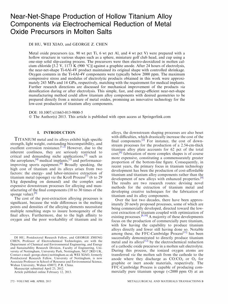
the top and bottomparts of themold. Themass of the finalslip-cast metal oxide precursor was approximately 2 g. Atthe final stages of slip injection, the gas-releasing hole wassealed quickly by the solidifying slip due to the smallquantity of slip permitting rapid water drainage. Thesyringe needle was kept in the injection hole during theprocess to create a hole on the cast, which would facilitatepost-reduction washing. Figures 1(a) through (c) illus-trates schematically this solid slip-casting method. Oncethe slip was injected into the mold, the water was removedby capillary action (Figure 1(a)), leaving a close-packeddeposit of metal oxide particles against the inner wall. Asthis draining process proceeded continuously, a cavity wasgenerated in the upper central part of the slip due to theinfluence of gravity (Figure 1(b)); this would result in anunevenwall thickness in the produced precursor. To insureuniform thickness, the plaster mold was rotated severaltimes during the process (Figure 1(c)). Following casting,the plaster mold was dried in a fume cupboard for 48 h,after which the syringe needle was removed, the moldopened, and the precursor exposed as shown inFigure 1(d). The slip-cast metal oxide precursor wasspherical in shape with a slightly reduced diameter ofapproximately 15.6 mm; this allowed it to be easilyreleased from the plaster mold due to contraction duringthe drying process. The hollow structure of the precursorcan be seen in Figure 1(e), where one such precursor wasintentionally fractured.
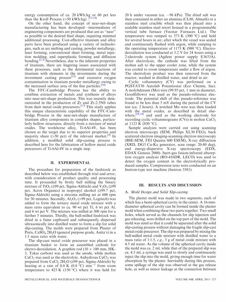
Other precursor shapes were also prepared, e.g., apellet and cup, for electro-deoxidation under the sameconditions to further demonstrate the feasibility of theFFC-Cambridge Process for near-net-shape productionof Ti-6Al-4V components. Figures 2(a) through (f)
depicts the solid slip-casting process for producingmetal oxide precursors in either of these shapes.In the slip-casting process, different mass ratios of the
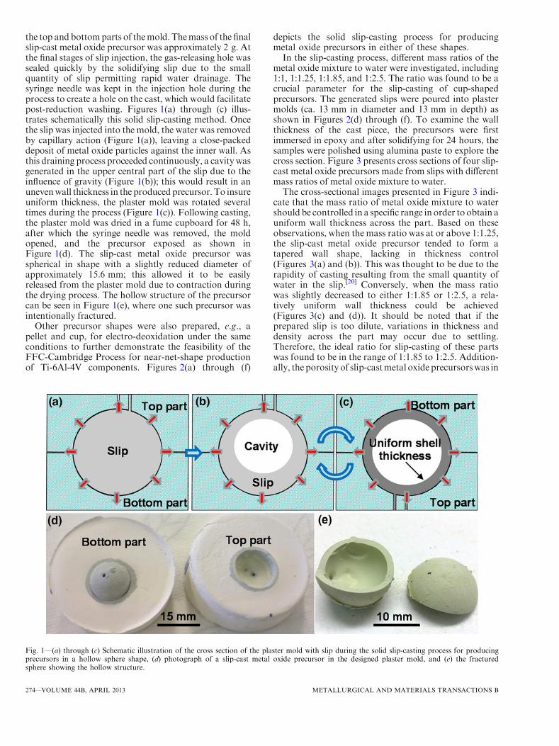
metal oxide mixture to water were investigated, including1:1, 1:1.25, 1:1.85, and 1:2.5. The ratio was found to be acrucial parameter for the slip-casting of cup-shapedprecursors. The generated slips were poured into plastermolds (ca. 13 mm in diameter and 13 mm in depth) asshown in Figures 2(d) through (f). To examine the wallthickness of the cast piece, the precursors were firstimmersed in epoxy and after solidifying for 24 hours, thesamples were polished using alumina paste to explore thecross section. Figure 3 presents cross sections of four slip-cast metal oxide precursors made from slips with differentmass ratios of metal oxide mixture to water.The cross-sectional images presented in Figure 3 indi-
cate that the mass ratio of metal oxide mixture to watershould be controlled in a specific range in order to obtain auniform wall thickness across the part. Based on theseobservations, when the mass ratio was at or above 1:1.25,the slip-cast metal oxide precursor tended to form atapered wall shape, lacking in thickness control(Figures 3(a) and (b)). This was thought to be due to therapidity of casting resulting from the small quantity ofwater in the slip.[20] Conversely, when the mass ratiowas slightly decreased to either 1:1.85 or 1:2.5, a rela-tively uniform wall thickness could be achieved(Figures 3(c) and (d)). It should be noted that if theprepared slip is too dilute, variations in thickness anddensity across the part may occur due to settling.Therefore, the ideal ratio for slip-casting of these partswas found to be in the range of 1:1.85 to 1:2.5. Addition-ally, the porosity of slip-castmetal oxide precursorswas in
Fig. 1—(a) through (c) Schematic illustration of the cross section of the plaster mold with slip during the solid slip-casting process for producingprecursors in a hollow sphere shape, (d) photograph of a slip-cast metal oxide precursor in the designed plaster mold, and (e) the fracturedsphere showing the hollow structure.
274—VOLUME 44B, APRIL 2013 METALLURGICAL AND MATERIALS TRANSACTIONS B
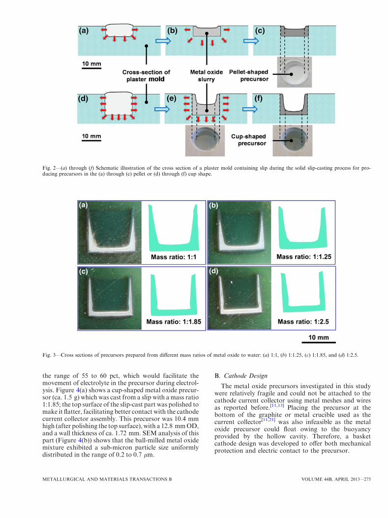
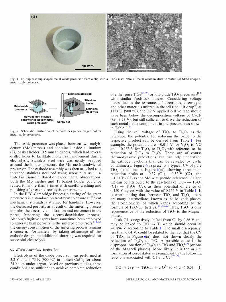
the range of 55 to 60 pct, which would facilitate themovement of electrolyte in the precursor during electrol-ysis. Figure 4(a) shows a cup-shaped metal oxide precur-sor (ca. 1.5 g) which was cast from a slip with amass ratio1:1.85; the top surface of the slip-cast part was polished tomake it flatter, facilitating better contact with the cathodecurrent collector assembly. This precursor was 10.4 mmhigh (after polishing the top surface), with a 12.8 mmOD,and a wall thickness of ca. 1.72 mm. SEM analysis of thispart (Figure 4(b)) shows that the ball-milled metal oxidemixture exhibited a sub-micron particle size uniformlydistributed in the range of 0.2 to 0.7 lm.
B. Cathode Design
The metal oxide precursors investigated in this studywere relatively fragile and could not be attached to thecathode current collector using metal meshes and wiresas reported before.[11,13] Placing the precursor at thebottom of the graphite or metal crucible used as thecurrent collector[11,21] was also infeasible as the metaloxide precursor could float owing to the buoyancyprovided by the hollow cavity. Therefore, a basketcathode design was developed to offer both mechanicalprotection and electric contact to the precursor.
Fig. 2—(a) through (f) Schematic illustration of the cross section of a plaster mold containing slip during the solid slip-casting process for pro-ducing precursors in the (a) through (c) pellet or (d) through (f) cup shape.
Fig. 3—Cross sections of precursors prepared from different mass ratios of metal oxide to water: (a) 1:1, (b) 1:1.25, (c) 1:1.85, and (d) 1:2.5.
METALLURGICAL AND MATERIALS TRANSACTIONS B VOLUME 44B, APRIL 2013—275
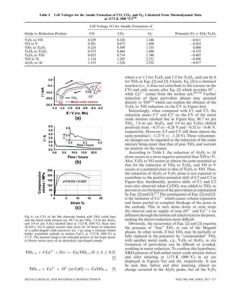
The oxide precursor was placed between two molyb-denum (Mo) meshes and contained inside a titanium(Ti) basket holder (0.5 mm thickness) which had severaldrilled holes to facilitate molten salt movement duringelectrolysis. Stainless steel wire was gently wrappedaround the holder to secure the Mo mesh-sandwichedprecursor. The cathode assembly was then attached to athreaded stainless steel rod using screw nuts as illus-trated in Figure 5. Based on experimental observations,both the Mo meshes and Ti basket holder could bereused for more than 3 times with careful washing andpolishing after each electrolysis experiment.
In the FFC-Cambridge Process, sintering of the greenprecursors is a standard pretreatment to ensure sufficientmechanical strength is attained for handling. However,the decreased porosity as a result of the sintering processimpedes the electrolyte infiltration and movement in thepores, hindering the electro-deoxidation process.Although fugitive agents have sometimes been employedto generate high porosity in the sintered precursors,[14,22]
the energy consumption of the sintering process remainsa concern. Fortunately, by taking advantage of thiscathode design, no additional sintering was required forsuccessful electrolysis.
C. Electrochemical Reduction
Electrolysis of the oxide precursor was performed at3.2 V and 1173 K (900 �C) in molten CaCl2 for about24 hours under argon. Based on previous studies, theseconditions are sufficient to achieve complete reduction
of either pure TiO2[22,23] or low-grade TiO2 precursors
[13]
with similar feedstock masses. Considering voltagelosses due to the resistance of electrodes, electrolyte,and other materials utilized in the cell (the ‘‘iR drop’’) at1173 K (900 �C), the 3.2 V applied cell voltage shouldhave been below the decomposition voltage of CaCl2(i.e., 3.23 V), but still sufficient to drive the reduction ofeach metal oxide component in the precursor as shownin Table I.[24]
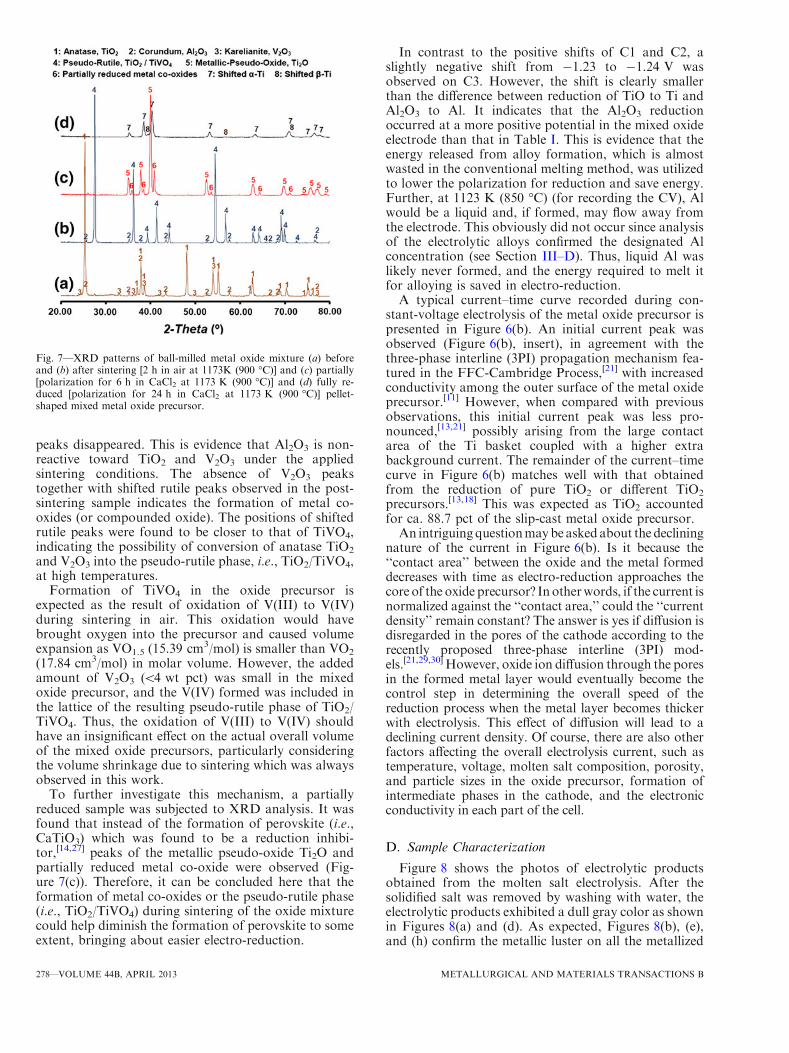
Using the cell voltage of TiO2 to Ti3O5 as thereference, the potential for reducing the oxide to therespective product can be derived from Table 1. Forexample, the potentials are �0.011 V for V2O3 to VOand �0.155 V for Ti3O5 to Ti2O3 with reference to thereduction of TiO2 to Ti3O5. These are of coursethermodynamic predictions, but can help understandthe cathode reactions that can be revealed by cyclicvoltammetry. Figure 6(a) presents a typical CV of pureTiO2 (solid line in Figure 6(a)), showing three mainreduction peaks at �0.37 (C1), �0.52 V (C2), and�1.23 V (C3) vs the Mo wire pseudo-reference. C1 andC2 can be attributed to the reactions of TiO2 fi Ti3O5
(C1) fi Ti2O3 (C2), as their potential difference of0.150 V agrees with the value of 0.155 V in Table I. Itis worth noting that, between TiO2 and Ti2O3, thereare many intermediates known as the Magneli phases,the stoichiometry of which varies according to theformula of TinO2n�1 (n ‡ 2).[11,25,26] Thus, Ti3O5 is onlyrepresentative of the reduction of TiO2 to the Magneliphases.Peak C3 is negatively shifted from C1 by 0.86 V and
may be linked to TiO fi Ti which should occur at�0.896 V according to Table I. The small discrepancy,less than 0.04 V, could be related to the fact that the CVof TiO2 in Figure 6(a) does not shown clearly thereduction of Ti2O3 to TiO. A possible cause is thedisproportionation of Ti2O3 to TiO and TiO2
[25] (or oneof the Magneli phases). More likely, it is the in situformation of perovskites as exemplified by the followingreactions associated with C1 and C2:[26–28]
TiO2 þ 2a e $ TiO2�a þ a O2� ð0 � a � 0:5Þ ½1�
Fig. 4—(a) Slip-cast cup-shaped metal oxide precursor from a slip with a 1:1.85 mass ratio of metal oxide mixture to water, (b) SEM image ofmetal oxide precursor.
Fig. 5—Schematic illustration of cathode design for fragile hollowmetal oxide precursors.
276—VOLUME 44B, APRIL 2013 METALLURGICAL AND MATERIALS TRANSACTIONS B
TiO2�a þ d Ca2þ þ 2d e $ CadTiO2�a ð0 � d � 0:5Þ½2�
TiO2�a þ Ca2þ þ O2� or CaOð Þ $ CaTiO3�a ½3�
where a is 1/3 for Ti3O5 and 1/2 for Ti2O3, and can be 0for TiO2 in Eqs. [2] and [3]. Clearly, Eq. [3] is a chemicalreaction (i.e., it does not contribute to the current on theCV) and only occurs after Eq. [1] which provides O2�,while Ca2+ comes from the molten salt.[26,28] Furtherreduction of these perovskite phases may proceeddirectly to TiO[27] which can explain the absence of theTi2O3 to TiO reduction on the CV in Figure 6(a).Interestingly, when compared with C1 and C2, the
reduction peaks C1¢ and C2¢ on the CV of the metaloxide mixture (dashed line in Figure 6(a), 88.7 wt pctTiO2, 7.4 wt pct Al2O3, and 3.9 wt pct V2O3) shiftedpositively from �0.37 to �0.28 V and �0.52 to �0.48 V,respectively. However, C3 and C3¢ still share almost thesame potential (�1.23 V vs �1.24 V). These voltammet-ric changes can be regarded as the reduction of the oxidemixture being easier than that of pure TiO2 and warrantan analysis on the causes.According to Table I, the reduction of Al2O3 to Al
alone occurs at a more negative potential than TiO to Ti.Also, V2O3 to VO occurs at almost the same potential asthat for the reduction of TiO2 to Ti3O5, and VO to Voccurs at a potential close to that of Ti2O3 to TiO. Thus,the reduction of Al2O3 or V2O3 alone is not expected tocontribute to the positive potential shift of C2 and C3 inFigure 6(a). Incidentally, positive shifts of C1 and C2were also observed when CaTiO3 was added to TiO2 toprevent in situ formation of the perovskites as representedby Eqs. [2] and [3].[27] The consequence of Eqs. [2] and [3]is the inclusion of Ca2+ which causes volume expansionand hence partial or complete blockage of the pores inthe cathode. This in turn slows down or even stopsthe removal and/or supply of ions (O2� and Ca2+) viadiffusion through themolten salt (electrolyte) in the pores,making the electro-reduction more difficult.Obviously, the occurrence of Eqs. [2] and [3] requires
the presence of ‘‘free’’ TiO2 or one of the Magneliphases. In other words, if free TiO2 may be partially orfully replaced in the precursor by ‘‘compounded’’ TiO2
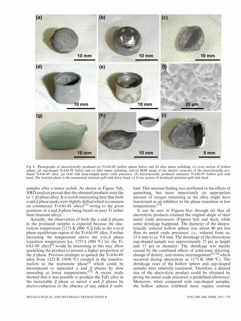
with another metal oxide, e.g., V2O3 or Al2O3, in situformation of perovskites can be difficult or avoided,resulting in easier reduction. To confirm this hypothesis,XRD patterns of ball-milled metal oxide mixture beforeand after sintering at 1173 K (900 �C) in air aredisplayed in Figures 7(a) and (b), respectively. It canbe seen that, before and after sintering, almost nochange occurred in the Al2O3 peaks, but all the V2O3
Table I. Cell Voltages for the Anodic Formation of CO, CO2, and O2, Calculated From Thermodynamic Data
at 1173 K (900 �C)[24]
Oxide to Reduction Product
Cell Voltage (V) for Anodic Formation of
Potential (V) vs TiO2/Ti3O5CO CO2 O2
V2O3 to VO 0.229 0.320 1.346 �0.011VO to V 0.581 0.672 1.698 �0.363TiO2 to Ti3O5 0.218 0.309 1.335 0.000Ti3O5 to Ti2O3 0.373 0.464 1.490 �0.155Ti2O3 to TiO 0.623 0.714 1.740 �0.405TiO to Ti 1.114 1.205 2.231 �0.896Al2O3 to Al 1.135 1.226 2.252 �0.917
Fig. 6—(a) CVs of the Mo electrode loaded with TiO2 (solid line)and the metal oxide mixture (ca. 88.7 wt pct TiO2, 7.4 wt pct Al2O3,and 3.9 wt pct V2O3) (dashed line) at 1123 K (850 �C). Scan rate:20 mV/s. (b) A typical current–time curve for 24 hours of reductionof a pellet-shaped oxide precursor (ca. 1 g) using a titanium basketholder assembled cathode in molten CaCl2 at 1173 K (900 �C) at3.2 V. The inserted image is the enlarged portion of the larger panel.(c) Stress–strain curve of an electrolytic cup-shaped sample.
METALLURGICAL AND MATERIALS TRANSACTIONS B VOLUME 44B, APRIL 2013—277
peaks disappeared. This is evidence that Al2O3 is non-reactive toward TiO2 and V2O3 under the appliedsintering conditions. The absence of V2O3 peakstogether with shifted rutile peaks observed in the post-sintering sample indicates the formation of metal co-oxides (or compounded oxide). The positions of shiftedrutile peaks were found to be closer to that of TiVO4,indicating the possibility of conversion of anatase TiO2
and V2O3 into the pseudo-rutile phase, i.e., TiO2/TiVO4,at high temperatures.
Formation of TiVO4 in the oxide precursor isexpected as the result of oxidation of V(III) to V(IV)during sintering in air. This oxidation would havebrought oxygen into the precursor and caused volumeexpansion as VO1.5 (15.39 cm3/mol) is smaller than VO2
(17.84 cm3/mol) in molar volume. However, the addedamount of V2O3 (<4 wt pct) was small in the mixedoxide precursor, and the V(IV) formed was included inthe lattice of the resulting pseudo-rutile phase of TiO2/TiVO4. Thus, the oxidation of V(III) to V(IV) shouldhave an insignificant effect on the actual overall volumeof the mixed oxide precursors, particularly consideringthe volume shrinkage due to sintering which was alwaysobserved in this work.
To further investigate this mechanism, a partiallyreduced sample was subjected to XRD analysis. It wasfound that instead of the formation of perovskite (i.e.,CaTiO3) which was found to be a reduction inhibi-tor,[14,27] peaks of the metallic pseudo-oxide Ti2O andpartially reduced metal co-oxide were observed (Fig-ure 7(c)). Therefore, it can be concluded here that theformation of metal co-oxides or the pseudo-rutile phase(i.e., TiO2/TiVO4) during sintering of the oxide mixturecould help diminish the formation of perovskite to someextent, bringing about easier electro-reduction.
In contrast to the positive shifts of C1 and C2, aslightly negative shift from �1.23 to �1.24 V wasobserved on C3. However, the shift is clearly smallerthan the difference between reduction of TiO to Ti andAl2O3 to Al. It indicates that the Al2O3 reductionoccurred at a more positive potential in the mixed oxideelectrode than that in Table I. This is evidence that theenergy released from alloy formation, which is almostwasted in the conventional melting method, was utilizedto lower the polarization for reduction and save energy.Further, at 1123 K (850 �C) (for recording the CV), Alwould be a liquid and, if formed, may flow away fromthe electrode. This obviously did not occur since analysisof the electrolytic alloys confirmed the designated Alconcentration (see Section III–D). Thus, liquid Al waslikely never formed, and the energy required to melt itfor alloying is saved in electro-reduction.A typical current–time curve recorded during con-
stant-voltage electrolysis of the metal oxide precursor ispresented in Figure 6(b). An initial current peak wasobserved (Figure 6(b), insert), in agreement with thethree-phase interline (3PI) propagation mechanism fea-tured in the FFC-Cambridge Process,[21] with increasedconductivity among the outer surface of the metal oxideprecursor.[11] However, when compared with previousobservations, this initial current peak was less pro-nounced,[13,21] possibly arising from the large contactarea of the Ti basket coupled with a higher extrabackground current. The remainder of the current–timecurve in Figure 6(b) matches well with that obtainedfrom the reduction of pure TiO2 or different TiO2
precursors.[13,18] This was expected as TiO2 accountedfor ca. 88.7 pct of the slip-cast metal oxide precursor.An intriguingquestionmaybe askedabout the declining
nature of the current in Figure 6(b). Is it because the‘‘contact area’’ between the oxide and the metal formeddecreases with time as electro-reduction approaches thecore of the oxide precursor? Inotherwords, if the current isnormalized against the ‘‘contact area,’’ could the ‘‘currentdensity’’ remain constant? The answer is yes if diffusion isdisregarded in the pores of the cathode according to therecently proposed three-phase interline (3PI) mod-els.[21,29,30] However, oxide ion diffusion through the poresin the formed metal layer would eventually become thecontrol step in determining the overall speed of thereduction process when the metal layer becomes thickerwith electrolysis. This effect of diffusion will lead to adeclining current density. Of course, there are also otherfactors affecting the overall electrolysis current, such astemperature, voltage, molten salt composition, porosity,and particle sizes in the oxide precursor, formation ofintermediate phases in the cathode, and the electronicconductivity in each part of the cell.
D. Sample Characterization
Figure 8 shows the photos of electrolytic productsobtained from the molten salt electrolysis. After thesolidified salt was removed by washing with water, theelectrolytic products exhibited a dull gray color as shownin Figures 8(a) and (d). As expected, Figures 8(b), (e),and (h) confirm the metallic luster on all the metallized
Fig. 7—XRD patterns of ball-milled metal oxide mixture (a) beforeand (b) after sintering [2 h in air at 1173K (900 �C)] and (c) partially[polarization for 6 h in CaCl2 at 1173 K (900 �C)] and (d) fully re-duced [polarization for 24 h in CaCl2 at 1173 K (900 �C)] pellet-shaped mixed metal oxide precursor.
278—VOLUME 44B, APRIL 2013 METALLURGICAL AND MATERIALS TRANSACTIONS B
samples after a minor polish. As shown in Figure 7(d),XRDanalysis proved that the obtained products were the(a+ b) phase alloy. It is worth mentioning here that botha andbphase peakswere slightly shiftedwhich is commonon commercial Ti-6Al-4V alloys[31] owing to the givenpositions of a and b phase being based on pure Ti ratherthan titanium alloys.
Actually, the observation of both the a and b phasesin the produced samples is expected because the elec-trolysis temperature [1173 K (900 �C)] falls in the a-to-bphase equilibrium region of the Ti-6Al-4V alloy. Furtherincreasing the temperature above the a-to-b phasetransition temperature [ca. 1253 k (980 �C) for the Ti-6A1-4V alloy][3] would be interesting as this may allowquenching the product to possess a higher proportion ofthe b phase. Previous attempts to quench the Ti-6Al-4Valloy from 1323 K (1050 �C) resulted in the transfor-mation to the martensite phase[3] which could bedecomposed to separated a and b phases by slowannealing at lower temperatures.[32] A recent studyshowed that it was possible to produce the TiZr alloy inthe metastable b phase or mixed a and b phases byelectro-reduction in the absence of any added b stabi-
liser. This unusual finding was attributed to the effects ofquenching, but more importantly an appropriateamount of oxygen remaining in the alloy might havefunctioned as an inhibitor to the phase transition at lowtemperatures.[33]
It can be seen in Figures 8(a) through (e) that allelectrolytic products retained the original shape of theirmetal oxide precursors (Figures 1(d) and 4(a)), whilesome shrinkage happened. The diameter of the electro-lytically reduced hollow sphere was about 40 pct lessthan its metal oxide precursor, i.e., reduced from ca.15.6 mm to ca. 9.4 mm. The shrinkage of the electrolyticcup-shaped sample was approximately 23 pct in heightand 13 pct in diameter. The shrinkage was mainlycaused by the combined effects of solid-state sintering,change of density, and atomic rearrangement[22,34] whichoccurred during electrolysis at 1173 K (900 �C). Theshrinkage rates of the hollow sphere and cup-shapedsamples were relatively consistent. Therefore, a desiredsize of the electrolytic product could be obtained bygiving the metal oxide precursor a predefined allowance.Moreover, when compared with cup-shaped samples,the hollow spheres exhibited more regular contour
Fig. 8—Photographs of electrolytically produced (a) Ti-6Al-4V hollow sphere before and (b) after minor polishing, (c) cross section of hollowsphere, (d) cup-shaped Ti-6Al-4V before and (e) after minor polishing, and (f) SEM image of the interior structure of the electrolytically pro-duced Ti-6Al-4V alloy. (g) Golf club head-shaped metal oxide precursor, (h) electrolytically produced miniature Ti-6Al-4V hollow golf clubhead. The inserted photo is the commercial titanium golf club driver head. (i) Cross section of produced miniature golf club head.
METALLURGICAL AND MATERIALS TRANSACTIONS B VOLUME 44B, APRIL 2013—279
shrinkage. This phenomenon could be ascribed to boththe spherical shape which evenly distributes stress toavoid cracking and the inner cavity which functionsas a cushion to bear more inward shrinkage.Figure 8(c) presents an electrolytically reduced hollowsphere which was sectioned with uniform wall thicknessof ca. 1 mm. The small hole generated during the slip-casting process permitted water access during post-electrolysis washing for salt removal. In addition, theelectrolytic Ti-6Al-4V sample was broken by a pair ofpliers to produce a fracture surface which was used toexamine the interior structure under SEM. As shown inFigure 8(f), when compared with its metal oxide pre-cursor (Figure 4(b)), the electrolytic Ti-6Al-4V exhibiteda much less porous structure of heavily sintered nodularparticles than in similarly prepared Ti metal.[11,35] Theaverage porosity of the electrolytic products was in therange of 26 to 30 pct, implying an enhanced mechanicalstrength, which will be discussed below. Furthermore,by simply changing the plaster mold to a golf club headshape, a miniature hollow golf club head-shaped metaloxide precursor was fabricated (Figure 8(g)). After 24 hof electrolysis [3.2 V, 1173 K (900 �C)], a miniaturehollow Ti-6Al-4V golf club head was obtained(Figures 8(h) and (i)) which matches very well to theshape of a golf club driver head (see insert in Figure 8(h)).
Elemental composition and homogeneity are essentialfor titanium alloy properties.[36] Typically, the oxygencontent of the electrolytic products was approximately1970 ppm as measured by the LECO RO-416DR, whichwas significantly lower than that of titanium compo-nents produced by powder metallurgy.[16] A loweroxygen content can improve ductility.
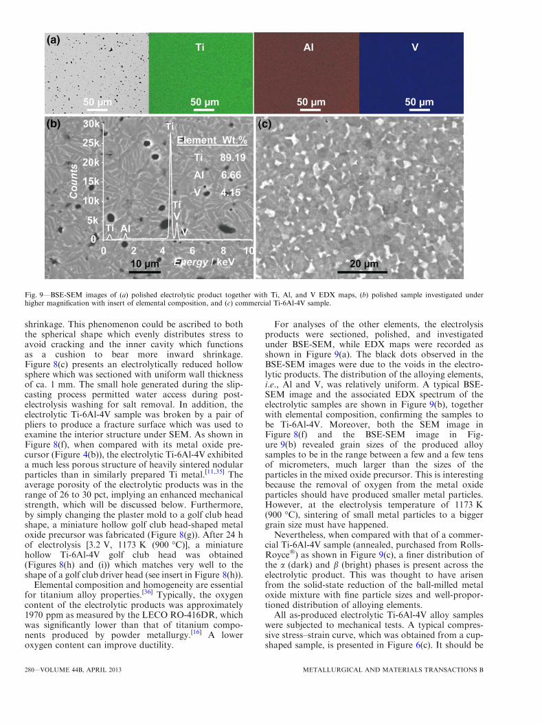
For analyses of the other elements, the electrolysisproducts were sectioned, polished, and investigatedunder BSE-SEM, while EDX maps were recorded asshown in Figure 9(a). The black dots observed in theBSE-SEM images were due to the voids in the electro-lytic products. The distribution of the alloying elements,i.e., Al and V, was relatively uniform. A typical BSE-SEM image and the associated EDX spectrum of theelectrolytic samples are shown in Figure 9(b), togetherwith elemental composition, confirming the samples tobe Ti-6Al-4V. Moreover, both the SEM image inFigure 8(f) and the BSE-SEM image in Fig-ure 9(b) revealed grain sizes of the produced alloysamples to be in the range between a few and a few tensof micrometers, much larger than the sizes of theparticles in the mixed oxide precursor. This is interestingbecause the removal of oxygen from the metal oxideparticles should have produced smaller metal particles.However, at the electrolysis temperature of 1173 K(900 �C), sintering of small metal particles to a biggergrain size must have happened.Nevertheless, when compared with that of a commer-
cial Ti-6Al-4V sample (annealed, purchased from Rolls-Royce�) as shown in Figure 9(c), a finer distribution ofthe a (dark) and b (bright) phases is present across theelectrolytic product. This was thought to have arisenfrom the solid-state reduction of the ball-milled metaloxide mixture with fine particle sizes and well-propor-tioned distribution of alloying elements.All as-produced electrolytic Ti-6Al-4V alloy samples
were subjected to mechanical tests. A typical compres-sive stress–strain curve, which was obtained from a cup-shaped sample, is presented in Figure 6(c). It should be
Fig. 9—BSE-SEM images of (a) polished electrolytic product together with Ti, Al, and V EDX maps, (b) polished sample investigated underhigher magnification with insert of elemental composition, and (c) commercial Ti-6Al-4V sample.
280—VOLUME 44B, APRIL 2013 METALLURGICAL AND MATERIALS TRANSACTIONS B
stated that the conditions, such as shape, dimension,and porosity, of the as-produced near-net-shape sampleswere not ideal for compression tests, which could havecontributed to the noticeable fluctuations in Figure 6(c).However, there was always an approximate linear regionon the stress–strain curve in the low stress region for allsamples tested, which was used to derive the Young’smodulus. The observed maximum compressive stresswas ca. 243 MPa and the corresponding modulus wasca. 14 GPa, which are relatively comparable with thoseof natural bones (2 to 200 MPa, and 0.1 to 20 GPa)[37]
and porous Ti-6Al-4V alloy produced by powdermetallurgical techniques (225 MPa, and 14 GPa with50 pct porosity).[38] Therefore, it could be concludedthat the electrolytic Ti-6Al-4V products exhibit enoughstrength to be directly used in some devices withoutfurther downstream processes such as smelting orpressing.
It is acknowledged that the samples produced in thiswork still contained too many voids as revealed byFigures 9(a) and (b) and obviously need further densi-fication for high stress applications. While post-electrol-ysis improvement of the products may be achieved byhigh-pressure sintering (e.g., hot isotropic pressing), ourfollow-on research will focus on changing the electrol-ysis from one step to two steps.[14] The first step will besame as that for electro-reduction with the second stepbeing a prolonged period of in situ sintering. In thesecond step, a lower cell voltage may be applied toprevent reoxidation of the product without too muchenergy input. The temperature of the cell may also beincreased in the second step to promote sintering,although this may be challenging in large-scale opera-tion. Last, but not the least, precursor fabricationshould be further investigated in relation to shape andproperty control in the near-net-shape product. Never-theless, highly dense oxide precursor is not recom-mended unless the product is, for example, a thin-walledvessel. This is because, for reduction of a bulkyprecursor (e.g.,>2 mm in the thinnest dimension), asufficiently porous structure is needed to enable theremoval of oxygen ions at an acceptable speed throughthe molten salt in the pores, instead of the solid phase.
IV. CONCLUSIONS
Ti-6Al-4V alloy components with complex shapes,such as hollow spheres and golf club heads, can bedirectly produced in the near-net shape from their metaloxide precursors via the FFC-Cambridge Process. Aninnovative plaster mold design is demonstrated forpreparation of hollow oxide precursors by slip-casting.Results from preliminary studies by cyclic voltammetryand XRD analysis suggest that V2O3 can assist thereduction of TiO2 by preventing in situ formation ofperovskites (e.g., CaTiO3) during electrolysis. Fabrica-tion and tests of a new and effective cathode assemblyare reported by utilizing a Ti basket and Mo mesh toaccommodate the hollow and fragile oxide precursors.This approach can obviate the need for sintering,reducing the time and energy consumption of the
process as a whole. The produced near-net-shapesamples possess a fine a- and b-phase structure andgood mechanical properties that are comparable withnatural bone and porous Ti-6Al-4V alloys produced bypowder metallurgy. We hope this report has pointed anew direction for development of cost-affordable near-net-shape production of engineering components withtitanium and other metal alloys.
ACKNOWLEDGMENTS
The authors thank S. Fletcher for the initial interestand discussion, the East Midlands Universities Associ-ation (EMUA) for a Sport-Related Studentship to D.Hu, the EPSRC for partial funding (EP/F026412/1and EP/J000582/1), and D. A. Jewell for assistance insome early experiments.
OPEN ACCESS
This article is distributed under the terms of theCreative Commons Attribution License which permitsany use, distribution, and reproduction in any med-ium, provided the original author(s) and the source arecredited.
REFERENCES
1. D. Knittel and J.B.C. Wu: in Mechanical Engineers’ Handbook,M. Kutz, ed., Wiley, New York, 1998, pp. 91–108.
2. G. Lutjering and J.C. Williams: Titanium, 2nd ed., Springer, NewYork, 2007.
3. C. Leyens and M. Peters: Titanium and Titanium Alloys: Funda-mentals and Applications, WILEY-VCH, Weinheim, 2003.
4. R.R. Boyer: Mater. Sci. Eng. A, 1996, vol. 213, pp. 103–14.5. H.J. Rack and J.I. Qazi: Mater. Sci. Eng. C, 2006, vol. 26,
pp. 1269–77.6. F.H. Froes: in Handbook of Materials Selection, M. Kutz, ed.,
Wiley, New York, 2002.7. W. Kroll: Trans. Electrochem. Soci., Ottawa, Canada, 1940,
pp. 35–47.8. EHK Technologies: Summary of Emerging Titanium Cost Reduc-
tion Technologies, 2004, p. 59.9. F.H. Froes, and M. Ashraf Imam: Key. Eng. Mater, 2010, vol. 436,
pp. 1–11.10. D.J. Fray: Int. Mater. Rev., 2008, vol. 53, pp. 317–25.11. G.Z. Chen, D.J. Fray, and T.W. Farthing: Nature, 2000, vol. 407,
pp. 361–64.12. D.J. Fray and G.Z. Chen: Mater. Sci. Technol., 2004, vol. 20,
pp. 295–300.13. M. Ma, D.H. Wang, W.W. Wang, X.H. Hu, X.B. Jin, and G.Z.
Chen: J. Alloys Compd., 2006, vol. 420, pp. 37–45.14. W. Li, X.B. Jin, F.L. Huang, and G.Z. Chen: Angew. Chem. Int.
Ed., 2010, vol. 49, pp. 3203–06.15. C. Ohkubo, I. Watanabe, J.P. Ford, H. Nakajima, T. Hosoi, and
T. Okabe: Biomaterials, 2000, vol. 21, pp. 421–28.16. J.C. Li and D.C. Dunand: Acta Mater., 2011, vol. 59, pp. 146–58.17. J.J. Peng, K. Jiang, W. Xiao, D.H. Wang, X.B. Jin, and G.Z.
Chen: Chem. Mater., 2008, vol. 20, pp. 7274–80.18. K. Jiang, X.H. Hu, H.J. Sun, D.H. Wang, X.B. Jin, Y.Y. Ren, and
G.Z. Chen: Chem. Mater., 2004, vol. 16, pp. 4324–29.19. G.H. Qiu, K. Jiang, M. Ma, D.H. Wang, X.B. Jin, and G.Z. Chen:
Z. Naturforsch., A: Phys. Sci., vol. 62A, pp. 292–302.20. D.W. Richerson: Modern Ceramic Engineering, 3rd ed., CRC
Press, Taylor & Francis Group, Boca Raton, 2006.
METALLURGICAL AND MATERIALS TRANSACTIONS B VOLUME 44B, APRIL 2013—281

21. G.Z. Chen, E. Gordo, and D.J. Fray: Metall. Mater. Trans. B,2004, vol. 35B, pp. 223–33.
22. R.L. Centeno-Sanchez, D.J. Fray, and G.Z. Chen: J. Mater. Sci.,2007, vol. 42, pp. 7494–7501.
23. D.T.L. Alexander, C. Schwandt, and D.J. Fray: Electrochim. Acta,2011, vol. 56, pp. 3286–95.
24. A. Roine: HSC Chemistry Version 6.12, Outokumpu Research OyInformation Service, Pori, 2006.
25. G.Z. Chen and D.J. Fray: J. Electrochem. Soc., 2002, vol. 149,pp. E455–E467.
26. K. Dring, R. Dashwood, and D. Inman: J. Electrochem. Soc.,2005, vol. 152, pp. E104–E113.
27. K. Jiang, X.H. Hu, M. Ma, D.H. Wang, G.H. Qiu, X.B. Jin,and G.Z. Chen: Angew. Chem. Int. Ed., 2006, vol. 45, pp. 428–32.
28. R. Bhagat, D. Dye, S.L. Raghunathan, R.J. Talling, D. Inman,B.K. Jackson, K.K. Rao, and R.J. Dashwood: Acta Mater., 2010,vol. 58, pp. 5057–62.
29. W. Xiao, X.B. Jin, Y. Deng, D.H. Wang, and G.Z. Chen: Chem.Eur. J., 2007, vol. 13, pp. 604–12.
30. Y. Deng, D.H. Wang, W. Xiao, X.B. Jin, X.H. Hu, and G.Z.Chen: J. Phys. Chem. B, 2005, vol. 109, pp. 14043–51.
31. T.K. Zhu and M.Q. Li: Mater. Charact., 2011, vol. 62, pp. 724–29.32. F.X. Gil Mur, D. Rodriguez, and J.A. Planell: J. Alloys Compd.,
1999, vol. 234, pp. 287–89.33. J.J. Peng, H.L. Chen, X.B. Jin, T. Wang, D.H. Wang, and G.Z.
Chen: Chem. Mater., 2009, vol. 21, pp. 5187–95.34. K. Dring, R. Bhagat, M. Jackson, R. Dashwood, and D. Inman:
J. Alloys Compd., 2006, vol. 419, pp. 103–09.35. G.Z. Chen and D.J. Fray: Trans. Inst. Min. Metall. C., 2006,
vol. 115, pp. 49–54.36. A. Mitchell: JOM, 1997, vol. 49, pp. 40–42.37. F.G. Evans: Artif. Limbs, 1969, vol. 13, pp. 37–48.38. S.R. Bhattarai, K.A.-R. Khalil, M. Dewidar, P.H. Hwang, H.K.
Yi, and H.Y. Kim: J. Biomed. Mater. Res., Part A, 2008, vol. 86A,pp. 289–99.
282—VOLUME 44B, APRIL 2013 METALLURGICAL AND MATERIALS TRANSACTIONS B