nchrp - assessment and rehabilitation of existing culverts · national cooperative highway research...
TRANSCRIPT
Assessment and Rehabilitation ofExisting Culverts
A Synthesis of Highway Practice
NATIONALCOOPERATIVE HIGHWAYRESEARCHPROGRAMNCHRP
SYNTHESIS 303
NAT IONAL COOPERAT IVE H IGHWAY RESEARCH PROGRAM
NCHRP SYNTHESIS 303
Assessment and Rehabilitation ofExisting Culverts
A Synthesis of Highway Practice
CONSULTANTDAVID C. WYANT
DW Enterprises
TOPIC PANEL
JOSH BEAKLEY, American Concrete Pipe AssociationUMAKANT DASH, Pennsylvania Department of Transportation
JAMES B. GODDARD, Advanced Drainage Systems, Inc.JAMES J. HILL, Minnesota Department of Transportation
MICHAEL G. KATONA, Washington State UniversitySTEPHEN F. MAHER, Transportation Research Board
SHAWN A. MCLEMORE, H.W. Lochner, Inc.JOHN D. O’FALLON, Federal Highway Administration
BRIAN C. ROBERTS, National Corrugated Steel Pipe AssociationPHILIP L. THOMPSON, U.S. Department of Transportation
MARTIN VAN ZANDT, California Department of Transportation
SUBJECT AREAS
Bridges, Other Structures, Hydraulics and Hydrology, Materials and Construction, and Maintenance
Research Sponsored by the American Association of State Highway and Transportation Officialsin Cooperation with the Federal Highway Administration
TRANSPORTATION RESEARCH BOARD — THE NATIONAL ACADEMIES
WASHINGTON, D.C.2002
NATIONAL COOPERATIVE HIGHWAY RESEARCH PROGRAM
Systematic, well-designed research provides the most effectiveapproach to the solution of many problems facing highway ad-ministrators and engineers. Often, highway problems are of localinterest and can best be studied by highway departments indi-vidually or in cooperation with their state universities and others.However, the accelerating growth of highway transportation de-velops increasingly complex problems of wide interest to high-way authorities. These problems are best studied through a coor-dinated program of cooperative research.
In recognition of these needs, the highway administrators ofthe American Association of State Highway and TransportationOfficials initiated in 1962 an objective national highway researchprogram employing modern scientific techniques. This programis supported on a continuing basis by funds from participatingmember states of the Association and it receives the full coopera-tion and support of the Federal Highway Administration, UnitedStates Department of Transportation.
The Transportation Research Board of the National ResearchCouncil was requested by the Association to administer the re-search program because of the Board’s recognized objectivityand understanding of modern research practices. The Board isuniquely suited for this purpose as it maintains an extensivecommittee structure from which authorities on any highwaytransportation subject may be drawn; it possesses avenues ofcommunication and cooperation with federal, state, and localgovernmental agencies, universities, and industry; its relationshipto the National Research Council is an insurance of objectivity; itmaintains a full-time research correlation staff of specialists inhighway transportation matters to bring the findings of researchdirectly to those who are in a position to use them.
The program is developed on the basis of research needsidentified by chief administrators of the highway and transporta-tion departments and by committees of AASHTO. Each year,specific areas of research needs to be included in the program areproposed to the National Research Council and the Board by theAmerican Association of State Highway and Transportation Offi-cials. Research projects to fulfill these needs are defined by theBoard, and qualified research agencies are selected from thosethat have submitted proposals. Administration and surveillance ofresearch contracts are the responsibilities of the National Re-search Council and the Transportation Research Board.
The needs for highway research are many, and the NationalCooperative Highway Research Program can make significantcontributions to the solution of highway transportation problemsof mutual concern to many responsible groups. The program,however, is intended to complement rather than to substitute foror duplicate other highway research programs.
NOTE: The Transportation Research Board, the National ResearchCouncil, the Federal Highway Administration, the American Associa-tion of State Highway and Transportation Officials, and the individ-ual states participating in the National Cooperative Highway Re-search Program do not endorse products or manufacturers. Trade ormanufacturers’ names appear herein solely because they are con-sidered essential to the object of this report.
NCHRP SYNTHESIS 303
Project 20-5 FY 1999 (Topic 31-03)ISSN 0547-5570ISBN 0-309-069203Library of Congress Control No. 2002109707© 2002 Transportation Research Board
Price $15.00
NOTICE
The project that is the subject of this report was a part of the National Co-operative Highway Research Program conducted by the Transporta-tion Research Board with the approval of the Governing Board of theNational Research Council. Such approval reflects the Governing Board’sjudgment that the program concerned is of national importance and appro-priate with respect to both the purposes and resources of the National Re-search Council.
The members of the technical committee selected to monitor this proj-ect and to review this report were chosen for recognized scholarly com-petence and with due consideration for the balance of disciplines appro-priate to the project. The opinions and conclusions expressed or impliedare those of the research agency that performed the research, and, whilethey have been accepted as appropriate by the technical committee, theyare not necessarily those of the Transportation Research Board, the Na-tional Research Council, the American Association of State Highway andTransportation Officials, or the Federal Highway Administration of the U.S.Department of Transportation.
Each report is reviewed and accepted for publication by the technicalcommittee according to procedures established and monitored by theTransportation Research Board Executive Committee and the GoverningBoard of the National Research Council.
The National Research Council was established by the National Acad-emy of Sciences in 1916 to associate the broad community of science andtechnology with the Academy’s purposes of furthering knowledge and ofadvising the Federal Government. The Council has become the principaloperating agency of both the National Academy of Sciences and the Na-tional Academy of Engineering in the conduct of their services to thegovernment, the public, and the scientific and engineering communities. Itis administered jointly by both Academies and the Institute of Medicine.The National Academy of Engineering and the Institute of Medicine wereestablished in 1964 and 1970, respectively, under the charter of the Na-tional Academy of Sciences.
The Transportation Research Board evolved in 1974 from the High-way Research Board, which was established in 1920. The TRB incorpo-rates all former HRB activities and also performs additional functions un-der a broader scope involving all modes of transportation and theinteractions of transportation with society.
Published reports of the
NATIONAL COOPERATIVE HIGHWAY RESEARCH PROGRAM
are available from:
Transportation Research BoardNational Research Council2101 Constitution Avenue, N.W.Washington, D.C. 20418
and can be ordered through the Internet at:
http://www.nationalacademies.org/trb/bookstore
Printed in the United States of America
PREFACE
FOREWORD By Staff TransportationResearch Board
A vast storehouse of information exists on nearly every subject of concern to highwayadministrators and engineers. Much of this information has resulted from both researchand the successful application of solutions to the problems faced by practitioners in theirdaily work. Because previously there has been no systematic means for compiling suchuseful information and making it available to the entire community, the American Asso-ciation of State Highway and Transportation Officials has, through the mechanism of theNational Cooperative Highway Research Program, authorized the Transportation Re-search Board to undertake a continuing project to search out and synthesize usefulknowledge from all available sources and to prepare documented reports on currentpractices in the subject areas of concern.
This synthesis series reports on various practices, making specific recommendationswhere appropriate but without the detailed directions usually found in handbooks or de-sign manuals. Nonetheless, these documents can serve similar purposes, for each is acompendium of the best knowledge available on those measures found to be the mostsuccessful in resolving specific problems. The extent to which these reports are usefulwill be tempered by the user’s knowledge and experience in the particular problem area.
This synthesis report will be of interest to department of transportation, county, andmunicipal engineers, as well as to other transportation professionals who are concernedwith the condition and maintenance of buried culverts and storm sewers. Its objective isto determine the state of the practice of pipe assessment, the selection of appropriate re-pair or rehabilitation methods, and the management aspects of a pipe program. This re-port provides information on plastic, concrete, and metal pipes and their appurtenances,including inlets, manholes, joints, and headwalls. It also provides information on howtransportation agencies have incorporated pipe assessment and corrective work (repair orrehabilitation) into a pipe management system and eventually into the larger transporta-tion management system. Rehabilitation specifications and methods of field report arepresented as well. The study presents what management systems and methods are beingused by transportation agencies to predict the service life of pipes.
Administrators, engineers, and researchers are continually faced with highway prob-lems on which much information exists, either in the form of reports or in terms of un-documented experience and practice. Unfortunately, this information often is scatteredand unevaluated and, as a consequence, in seeking solutions, full information on whathas been learned about a problem frequently is not assembled. Costly research findingsmay go unused, valuable experience may be overlooked, and full consideration may notbe given to available practices for solving or alleviating the problem. In an effort to cor-rect this situation, a continuing NCHRP project has the objective of reporting on com-mon highway problems and synthesizing available information. The synthesis reportsfrom this endeavor constitute an NCHRP publication series in which various forms ofrelevant information are assembled into single, concise documents pertaining to specifichighway problems or sets of closely related problems.
This report of the Transportation Research Board contains information derived fromsurvey responses from 39 state transportation agencies (including Guam and PuertoRico), 21 federal agencies, and 15 localities, including county road commissions, publicworks departments, and county engineering departments. In addition, a literature searchwas conducted to determine the current state of the practice.
To develop this synthesis in a comprehensive manner and to ensure inclusion of sig-nificant knowledge, the available information was assembled from numerous sources, in-cluding a large number of state highway and transportation departments. A topic panel ofexperts in the subject area was established to guide the author’s research in organizingand evaluating the collected data, and to review the final synthesis report.
This synthesis is an immediately useful document that records the practices that wereacceptable within the limitations of the knowledge available at the time of its preparation.As the processes of advancement continue, new knowledge can be expected to be addedto that now at hand.
CONTENTS
1 SUMMARY
5 CHAPTER ONE INTRODUCTION AND RESEARCH APPROACHBackground, 5Purpose and Scope, 6Research Approach, 6Organization of Synthesis, 7
8 CHAPTER TWO METHODS TO ASSESS PIPE CONDITION
22 CHAPTER THREE METHODS TO SELECT PIPE REPAIR AND REHABILITATIONPipe Repair, 22Pipe Rehabilitation, 22
31 CHAPTER FOUR PIPE MANAGEMENT ADMINISTRATIONManagement Systems, 31Record Keeping, 32Specifications, 32
34 CHAPTER FIVE CONCLUSIONS
36 REFERENCES
38 GLOSSARY
39 APPENDIX A SURVEY QUESTIONNAIRE
43 APPENDIX B AGENCIES RESPONDING TO QUESTIONNAIRE
46 APPENDIX C EXAMPLES OF PIPE GUIDELINES AND SPECIFICATIONS:MAINE DOT’s CROSS CULVERT AND STRUT GUIDELINES
61 APPENDIX D WYOMING DOT’s SPECIAL PROVISION FOR PIPELINER INSTALLATION
65 APPENDIX E NYSDOT’s REHABILITATION OF CULVERT AND STORMDRAIN PIPE SPECIFICATIONS
68 APPENDIX F PIPE DURABILITY
ACKNOWLEDGMENTS
David C. Wyant, DW Enterprises, Crozet, Virginia, was responsi-ble for collection of the data and preparation of the report.
Valuable assistance in the preparation of this synthesis was pro-vided by the Topic Panel, consisting of Josh Beakley, Director ofTechnical Services, American Concrete Pipe Association; UmakantDash, Bridge Q & A Engineer, Pennsylvania Department of Trans-portation; James B. Goddard, Chief Engineer, Advanced DrainageSystems, Inc.; James J. Hill, Structural Design Engineer, MinnesotaDepartment of Transportation (retired); Michale G. Katona, Profes-sor/Chair, Department of Civil and Environmental Engineering,Washington State University; Stephen F. Maher, Senior Program Of-ficer, Transportation Research Board; Shawn A. MCLemore, H.W.Lochner, Inc., Tallahassee, Florida; John D. O’Fallon, Bridge Re-search Engineer, Turner Fairbank Highway Research Center, Fed-eral Highway Administration; Brian C. Roberts, Executive Director,National Corrugated Steel Pipe Association; Philip L. Thompson, Senior
Hydraulics Engineer, Federal Highway Administration, U.S. Depart-ment of Transportation; and Martin Van Zandt, Deputy District Director,Maintenance and Operations, California Department of Transportation.
This study was managed by Jon Williams, Manager, SynthesisStudies who worked with the consultant, the Topic Panel, and theProject 20-5 Committee in the development and review of the report.Assistance in project scope development was provided by Donna L.Vlasak, Senior Program Officer. Don Tippman was responsible forediting and production. Cheryl Keith assisted in meeting logistics anddistribution of the questionnaire and draft reports.
Crawford F. Jencks, Manager, National Cooperative Highway Re-search Program, assisted the NCHRP 20-5 Committee and the Synthesisstaff.
Information on current practice was provided by many highwayand transportation agencies. Their cooperation and assistance areappreciated.
ASSESSMENT AND REHABILITATION OFEXISTING CULVERTS
SUMMARY The deterioration of pipes and culverts is a growing problem for transportation agencies. Astransportation drainage infrastructures age, the need for repair or rehabilitation often be-comes more critical. As a result, the number of pipes and culverts being repaired or reha-bilitated is increasing each year.
Transportation agencies have more pipes and culverts than bridge structures in theirtransportation systems. (Throughout this report, the term “pipes” refers to both pipes andculverts.) The investment in and the importance of these pipes in the overall transportationsystem are substantial. Most pipes, however, are not seen by the traveling public and be-come noticeable only when a problem arises, such as settlement in the roadway or flooding.Occasionally there is an accident because an unexpected pipe failure, causes a large settle-ment in the road surface. A less frequent but important problem that can be caused by afailed pipe is pollution leaking into the surrounding soil. These potential pollutants can belost through the joints of a pipe and can enter the groundwater or attach on to the soil parti-cles for extended periods of time.
The investment in these mostly unseen facilities can represent a significant portion of thetotal investment a transportation agency makes in the transportation system. When a pipefails there can be additional associated costs as well; for example, the higher cost to a trans-portation agency of an unplanned activity and the associated costs to the traveling publicwith travel delay and possibly detour costs when partial or complete closure of a roadway isnecessary.
An agency that monitors and inventories its pipes and knows their condition may benefitfrom the smaller pipe management costs that come from eliminating or significantly reduc-ing the number of failures. Also, the traveling public will benefit from a pipe managementsystem because traffic delays and the occasional accidents because of a failed pipe areminimized.
Guidelines need to be developed and implemented to systematically track and assess thecondition of pipes over time. The data collected during these assessments should be kept ina pipe management system for better management of all pipes, scheduling of maintenanceactivities, justification of funding needs, prioritization of pipe work, and any other analysisthat may arise.
This synthesis study was initiated to determine the state of the practice of pipe assess-ment, the selection of appropriate repair or rehabilitation methods, and the management as-pects of a pipe program. The study reports on information collected regarding the state ofthe practice for plastic, concrete, and metal pipes and their appurtenances, such as inlets,outlets, joints, access holes, junction boxes, wingwalls, endwalls, and headwalls. It also
2
provides information on how transportation agencies have incorporated pipe assessment andcorrective work (repair or rehabilitation) into a pipe management system and eventually intothe larger transportation management system. Rehabilitation specifications and methods ofrecord keeping of field reports are presented as well. The study determines what manage-ment systems and methods are being used by transportation agencies to predict the servicelife of pipes.
A questionnaire was developed to survey local, state, and federal transportation agencies.The questionnaire requested information about each agency’s inspection program, mainte-nance program, record keeping, material specifications, service-life predictions, manage-ment system, and guidelines for assessment, repair, and rehabilitation. In addition to thequestionnaire, transportation agencies were requested to provide documents related to thequestions asked in the survey; that is, data forms, inspection reports, specifications, andguidelines.
A second means of determining the state of the practice for this synthesis was throughliterature searches. From these searches, guidelines, methodologies, management systems,and service-life requirements of pipes used by transportation agencies and others were alsodiscovered. The literature searches were used to locate additional information and, in somecases, provided more detail on the information received from the questionnaire responses.
Agency guidelines for pipe assessment vary from none to a comprehensive system. Alimited number of transportation agencies have guidelines that range from a single page to afully documented system. The Pennsylvania, California, Minnesota, and North Carolina De-partments of Transportation (DOTs) and the Harford County (Maryland) Department ofPublic Works have one-page forms for collecting pipe data. The Connecticut, Maine, andNew York State DOTs and the Maryland State Highway Administration have more exten-sive pipe programs. Maine’s program presently supplies its data to a centralized pipe data-base that can be accessed from headquarters over their computer network. This database isbeing proposed as a data subset in the Maine DOT’s data warehouse, which is under devel-opment. The ultimate goal is to have the data warehouse be the major data source for theirtransportation management system, the Transportation Integrated Network InformationSystem. This system would allow management and maintenance personnel to performanalyses not possible several years ago and be more proactive, rather than reactive, in theirpipe management program. In the interim, however, the centralized pipe database is themost inclusive data source for pipes in the DOT. Similar strategies to mitigate all transpor-tation data, including pipe data, into a data warehouse for use in a larger transportation man-agement system enterprise are being implemented in other states.
Most of the transportation agencies surveyed do not have methods to select types of piperepair. The type of repair is dictated by the pipe defect and the experience of the repair per-sonnel. In rehabilitation work, the only method used by some states is the service-life–dura-bility relationship.
Transportation agencies have developed or borrowed charts from other agencies for fac-tors such as pH, resistivity, and thickness of pipe. Most local agencies use their respectivestate DOT’s charts, specifications for rehabilitation, and guidelines for assessment if theypursue a pipe management system. The Local Technical Assistance Program (LTAP) of theFHWA has developed a culvert management system (CMS) for local governments thatcould be used by local agencies and others for guidance in establishing a pipe program.None of the responding agencies, however, including the local agencies, indicated that they
3
used this product in their work. A manual, field guide, training course, and computer soft-ware program were produced by the LTAP for the CMS. The computer program containsfive modules (inventory, condition, work needs, work funding, and schedule) and covers allthe elements of a pipe program. Each module has a flow diagram and the data forms neededfor successful completion. The other essential supporting program documents are includedin the CMS: a manual with the details and background information, a guide for fieldwork,and a training course for the users of the system.
Very few agencies keep records on pipe conditions. When a preventative maintenanceprogram is established, the records should become a part of the program and be kept forverification and history tracking. These records can be used to determine the rate of deterio-ration of a pipe, aid in the frequency of scheduling inspections, and assist in determining theappropriate time to repair or rehabilitate a deteriorating pipe.
The findings from this study suggest the following:
• That the establishment of a preventative maintenance program would help transporta-tion agencies manage the pipes in their systems.
• That the data collected from the assessments could be stored in, at a minimum, a cen-tralized pipe database, so that users would have access to the data for decision making.
In addition to the maintenance program and a centralized database, specifications areneeded so that contractors will understand the requirements and what is expected duringpipe repair or rehabilitation work. Most transportation agencies currently use constructionspecifications that are developed to address issues and requirements when a pipe is installedin an open cut. However, when a pipe is lined (trenchless pipe rehabilitation), the require-ments, issues, and processes are different and require a different set of specifications that arespecific for this type of work. At a minimum, the agency could use ASTM SpecificationA979/A979M-97, Standard Specification of Concrete Pavements and Linings Installed inCorrugated Steel Structures in the Field, as a guide for lining a pipe.
The pooling of funds by agencies to develop a comprehensive pipe management systemmay also be useful. A comprehensive pipe management system might include guidelinesand photographs for inspection, frequency of inspections, standard data forms, guidelinesfor determining the appropriate corrective action (repair, rehabilitation, or replacement), re-cord-keeping procedures, analysis methods for determining pipe condition or deteriorationrate, and the economic analysis of the action to be taken. If an agency used such a system, itwould be managing the system (proactive) rather than being at the mercy of the system (re-active). To develop this system without one state being unduly financially burdened, a num-ber of states could pool their funds and share the cost of development. One agency could beresponsible for the administrative and day-to-day operations of the project and coordinatethe project activities with a consultant. An estimate of the cost of the project would need tobe determined, so that each state could share equally in the cost. At the conclusion of theproject each agency would have the latest technique and a system ready for implementationas described in the final report.
5
CHAPTER ONE
INTRODUCTION AND RESEARCH APPROACH
BACKGROUND
Within their transportation systems, transportation agen-cies are responsible for more pipes and culverts thanbridge structures. (Throughout this report, the term“pipes” refers to both pipes and culverts.) The invest-ment and importance of pipes in the overall transporta-tion system are enormous. Unlike in the case of bridges,the traveling public is not aware of most of these pipesbecause they are situated at the bottom of slopes and, insome cases, under deep fills. The location and condition ofthese pipes becomes noticeable only when a problemarises, such as settlement in the roadway, flooding, etc. In1978, transportation agency investment in these mostly un-seen facilities was estimated to be approximately 10% ofthe total cost of the transportation system operations(NCHRP Synthesis of Highway Practice 50 1978). Cur-rently, more than 20 years later, it is estimated that this costcould exceed that amount.
In addition, there are associated costs to the transporta-tion agency (e.g., the higher cost of an unplanned activityonce a pipe fails) and to the traveling public (e.g., traveldelay and possibly detour costs) with the partial or com-plete closure of a roadway because of a pipe failure. There-fore, with the total cost to all parties potentially higher thanmost people realize, transportation agencies could benefitfrom the regular inspection of pipes and the assessment oftheir condition that could help minimize failures and reducecosts. To support the better management and analysis neededto accomplish such a proactive effort, pertinent data shouldbe kept in an accessible and user-friendly pipe manage-ment system, which can allow the agency decision makersto perform analyses related to their work responsibilities.
As the frequency and rate of deterioration of pipes in-creases, because of their increasing age of service and thechanging nature of watersheds that drain to them, the bene-fits of a proactive pipe system may exceed the cost of im-plementation. As the years of service increase, the wearand tear on the pipe increases because of physical actionssuch as abrasion, chemical actions due to environmentalchanges in the watershed, and changes in material proper-ties due to aging. Any of these changes can cause an in-crease in the deterioration rate of the pipe and trigger aneed for repair or rehabilitation before the planned servicelife is reached.
In the 1980s and 1990s, in an attempt to improve thepipe management, several agencies studied and evaluatedthe design methods used to determine the structural capac-ity of pipes constructed of various types of materials(Chambers et al. 1980; Mathioudakis and Agarwal 1996;Goble 1999; McGrath and Sagan 2000). Most of theseevaluations were needed because new pipe materials andlarger diameter pipes with a low bending stiffness and asmaller cross-sectional area were being introduced into theindustry. Of equal importance, where resources allow,would be an inspection program for determining the con-dition of an installed pipe and/or its rate of deterioration, aswell as the inclusion of these data into a pipe managementsystem, such as those in use in Pennsylvania, California,North Carolina, and Maine.
Transportation agencies generally have in place systemsto manage pavements, bridges, and signs. They have alsodeveloped and studied replacement and rehabilitation pro-cedures for pavements and bridges. Examples of thesesystems for secondary and local roads are described inNCHRP Report 222: Bridges on Secondary Highways andLocal Roads—Rehabilitation and Replacement (1980) andNCHRP Report 243: Rehabilitation and Replacement ofBridges on Secondary Highways and Local Roads (1981).These repair and rehabilitation procedures are usually partof a larger management system. Correspondingly, the es-tablishment of a pipe management system by an agencywould enhance the overall transportation system and givethe agency better control of its overall operations. Datafrom inspection reports, including the final construction in-spection report, could be analyzed as part of the pipe man-agement system.
Without a robust pipe management system, propermaintenance, and scheduling of inspections, it is more dif-ficult to perform repairs or rehabilitation in a timely andproactive manner. In other words, there is an increasedlikelihood that a pipe will deteriorate to such an unsatis-factory state that the riding surface of the road will dip or,worse, fail completely, and repair or rehabilitation of thepipe will need to be done immediately. An established pipemanagement system would provide an agency with a de-finitive methodology that could be used to justify thefunding needed for pipes, assist the decision maker in de-termining the options available for repair or rehabilitation,and be beneficial for proper pipe maintenance.
6
To have a fully functional system, an inventory of allpipes, an assessment methodology, initial and periodicassessments, options for repair or rehabilitation, andlinkage into a larger management or executive systemneed to be established. Several years ago, the NationalAssociation of Sewer Service Companies (NASSCO)realized the importance of a fully functional system andin response developed their Manual of Practices(NASSCO 1996). This document covers methods ofgathering data, guidelines for using inspection cameras,assessment of conditions, defect rating codes, modeling,rehabilitation methods, materials, and life-cycle and least-cost analyses. Recently, the FHWA, through the Local Tech-nical Assistance Program (LTAP), developed a culvert man-agement system (CMS) for local governments to pro-vide guidance and direction to local agencies and othersin implementing a pipe management program (Thomp-son 2000). A manual containing background informa-tion and the details of the system was published. In ad-dition, a field manual was created to aid the pipeinspector during the evaluation. A training course wasdeveloped to familiarize all personnel involved with thepipe program and specifically the CMS. The final productof the CMS is a computer software program designed toexpedite the implementation process. The computer pro-gram contains five modules with flow diagrams and dataforms: inventory of the culverts, condition and ratings,work needs (repair or rehabilitation), work funding andprioritization, and scheduling (time of the year and whetherin-house or contract).
A related topic to the subject of this synthesis is pipedurability, which is discussed in Appendix F.
PURPOSE AND SCOPE
This study was initiated to determine the state of the prac-tice in pipe assessment and in the selection of appropriaterepair and/or rehabilitation methods. In addition, the studywas undertaken to determine how pipe assessment and cor-rective work fit into the larger transportation managementsystem and what efforts, research or otherwise, are neededto implement a pipe management system. This synthesishad the following six objectives:
1. To determine what guidelines were being used bytransportation agencies to assess the conditions ofpipes.
2. To determine what guidelines were being used to se-lect the methodology to repair or rehabilitate a dam-aged pipe.
3. To determine what methods were being used to storeinspection and maintenance records.
4. To determine what management systems were beingused with an agency’s assessment program.
5. To determine what methods were being used byagencies to predict the service life of pipes.
6. To determine what material specifications were beingused during repair or rehabilitation of pipes.
The scope of this synthesis includes plastic, concrete,and metal pipes. System appurtenances such as inlets, out-lets, joints, manholes, junction boxes, headwalls, endwalls,and wingwalls are included as well. Cast-in-place struc-tures, box culverts, and bridges are not covered.
RESEARCH APPROACH
Two approaches were taken to achieve the study objec-tives: (1) a questionnaire was used to survey transportationagencies regarding their practices concerning pipe assess-ment and rehabilitation, and (2) a literature search was per-formed to determine the state of the practice.
Questionnaire
Organization
The questionnaire was kept short to make its completioneasy for respondents and to maximize the number of re-sponses. In addition, to make the respondent’s role stilleasier, the questionnaire was primarily a “yes/no” surveyand requested that copies of an agency’s supporting docu-mentation be returned with the survey. In general, thequestionnaire requested information about the agency’s in-spection program, maintenance program, record keeping,guidelines for assessment, repair and rehabilitation, mate-rial specifications, service-life predictions, and manage-ment system. A copy of the questionnaire is provided asAppendix A.
The questionnaire was specifically structured to deter-mine how an agency does pipe assessments, what theagency does with the data collected from these assess-ments, and if the agency has a management system toincorporate the collected data. In addition, the question-naire was designed to ascertain if guidelines were used todetermine the method of repair or rehabilitation from theinspection data and any service-life data used by theagency.
The survey questions were designed to provide a logicalapproach to pipe assessments. First, as an overview of thesurvey approach, it was important to know if an agencyhad preventative and/or inspection programs. If pro-grams were established within the agency, the frequencyof the inspections and records and data kept were of in-terest. The questionnaire also asked if the agency hadguidelines to assess pipe and appurtenance conditions
7
and, if so, were there additional guidelines to determinethe best method of repair or rehabilitation. In addition, thequestionnaire was used to determine if there were materialspecifications used to guide rehabilitation work and if theagency had methods for considering the service life ofpipes in their decisions. The final area of interest on thequestionnaire was whether the agency uses some type ofmanagement system to schedule future inspections, per-form advanced analyses, and justify funding requests.
A total of 155 questionnaires were sent to various trans-portation agencies including all state departments of trans-portation (DOTs), as well as those in Puerto Rico, Guam,and the District of Columbia; a number of federal agencies;and a large number of localities, including county roadcommissions, county engineering departments, publicworks departments, county utility departments, and parkand recreation departments. A list of respondents is pro-vided in Appendix B.
Rate of Return
The rate of return from state DOTs (including Guam andPuerto Rico) was 75% (39 of 52). Localities (including theDistrict of Columbia) returned 40% (15 of 38) and federalagencies 32% (21 of 65). The return rate for all agencieswas 48% (75 of 155). Several agencies also provided sup-porting documents. Details of the responses are reviewedin the following chapters.
Literature Review
Several keyword searches were done using TRIS, theTransportation Research Information Services, TRB’s bib-liographic transportation database. Other searches wereconducted through AASHTO, the University of Virginia’spublic library, and the Internet. Information discoveredduring these searches covering guidelines, methodologies,management systems, and the service life of pipes is dis-cussed in subsequent chapters.
ORGANIZATION OF SYNTHESIS
This synthesis is organized into five chapters (includingthis introduction) and six appendixes. Chapters 2 and 3cover the methods used by transportation agencies to as-sess pipe conditions and select pipe repair or rehabilitationmethods. Chapter 4 discusses the management systemsused in pipe programs, the issue of record keeping with re-gard to inspection and preventive maintenance data re-ports, and the material specifications used during pipe re-habilitation work. Chapter 5 summarizes the synthesisfindings and suggests areas where further action can betaken. Appendix A is the questionnaire and Appendix Bprovides the names and addresses of the respondents. Ap-pendixes C, D, and E contain supporting documents, speci-fications, and examples of pipe guidelines provided byseveral respondents. Appendix F is an added section onpipe durability.
8
CHAPTER TWO
METHODS TO ASSESS PIPE CONDITION
To determine whether a pipe needs to be repaired, reha-bilitated, or replaced, a thorough pipe inspection needs tobe conducted and a report of the findings needs to be re-corded. The first step in a pipe inspection program is toestablish a standard set of guidelines, under which all in-spectors will perform inspections in the same manner andthe data will be consistently collected. To ensure a clearunderstanding of these guidelines and what is expected ofthe inspector, pipe inspectors should be trained in the useof the guidelines, the data that are to be collected, and howthe data are to be used in the analysis of pipe conditions.Also, the inspector should be trained to identify defects, toidentify the severity of the defects, and to complete the in-spection reports essential to the record keeping.
Another element important to a successful pipe inspec-tion program is a regular inspection schedule, similar tothat provided in the National Bridge Inspection Standards(NBIS). NBIS structures are inspected on a 2-year cycleaccording to NBIS regulation 23 CFR 650.305. There is nonational standard inspection schedule for pipes similar tothe schedule for NBIS structures. Results from the surveyconfirmed that there is no standard state and local inspec-tion cycle being followed by transportation agencies.
Ring (1984) suggested that major pipes be inspected atleast every 3 years and more often where conditions areharsh. In 1986, the FHWA required that inspections be per-formed once every 2 years rather than every 3 years (Arnoult
1986). However, the FHWA allows states to perform lessfrequent inspection of NBIS structures on a case-by-casebasis if justified. If conditions are mild where the structureis installed, the reporting agency can perform the inspec-tion every 4 years with FHWA approval.
By establishing a regular inspection schedule for pipes,an agency could inspect individual on a different schedulewhen conditions warrant and guidelines established by theagency allow. This exception to the regularly scheduled in-spection cycle would be similar to that outlined by theNBIS policy. An inspection cycle for pipes may also varydepending on the size of the pipe and the risk associatedwith the pipe location. In areas where there is brackishwater, seawater, acidic runoff, or industrial discharge, theinspection cycle should be more frequent than normal. Forexample, the California Department of Transportation(Caltrans) performs inspections on larger pipes [thosespanning more than 6.1 m (20 ft)] more frequently than onsmaller pipes.
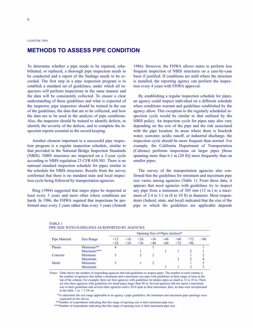
The survey of the transportation agencies also con-firmed that the guidelines for minimum and maximum pipesize varies among agencies (Table 1). From these data, itappears that most agencies with guidelines try to inspectany pipe from a minimum of 305 mm (12 in.) to a maxi-mum of 2.4 to 3.1 m (8 to 10 ft) in diameter. Most respon-dents (federal, state, and local) indicated that the size of thepipe to which the guidelines are applicable depends
TABLE 1 PIPE SIZE WITH GUIDELINES AS REPORTED BY AGENCIES
Opening Size of Pipes (inches)*
Pipe Material Size Range >12 >18 >24 >36 >48 >60 >72 >96<18 <24 <36 <48 <60 <72 <96
Plastic Minimum** 4 1 1Maximum*** 1 1 1 2 1
Concrete Minimum 5 2 2 1 2Maximum 2 2 4
Metal Minimum 5 1 2 1 2Maximum 1 1 2 3
Notes: Table shows the number of responding agencies that had guidelines to inspect pipes. The number in each column isthe number of agencies that define a minimum and a maximum size pipe with guidelines in their range of sizes at thetop of the column. For example, there are four agencies with guidelines for plastic pipes as small as 12 to 18 in. Thereare also three agencies with guidelines for metal pipes larger than 96 in. Several agencies did not report a maximumsize in their guidelines and several other agencies used a 20-ft span as their maximum; thus, no data were incorporatedin the table. 1 in. = 2.54 cm.
*To determine the size range applicable to an agency’s pipe guidelines, the minimum and maximum pipe openings wererequested on the survey.
**Number of respondents indicating that this range of opening size is their minimum pipe size.***Number of respondents indicating that this range of opening sizes is their maximum pipe size.
9
on the opening size, although a few agencies used the spanparallel with the centerline of the roadway [Caltrans andthe New York State Department of Transportation(NYSDOT)].
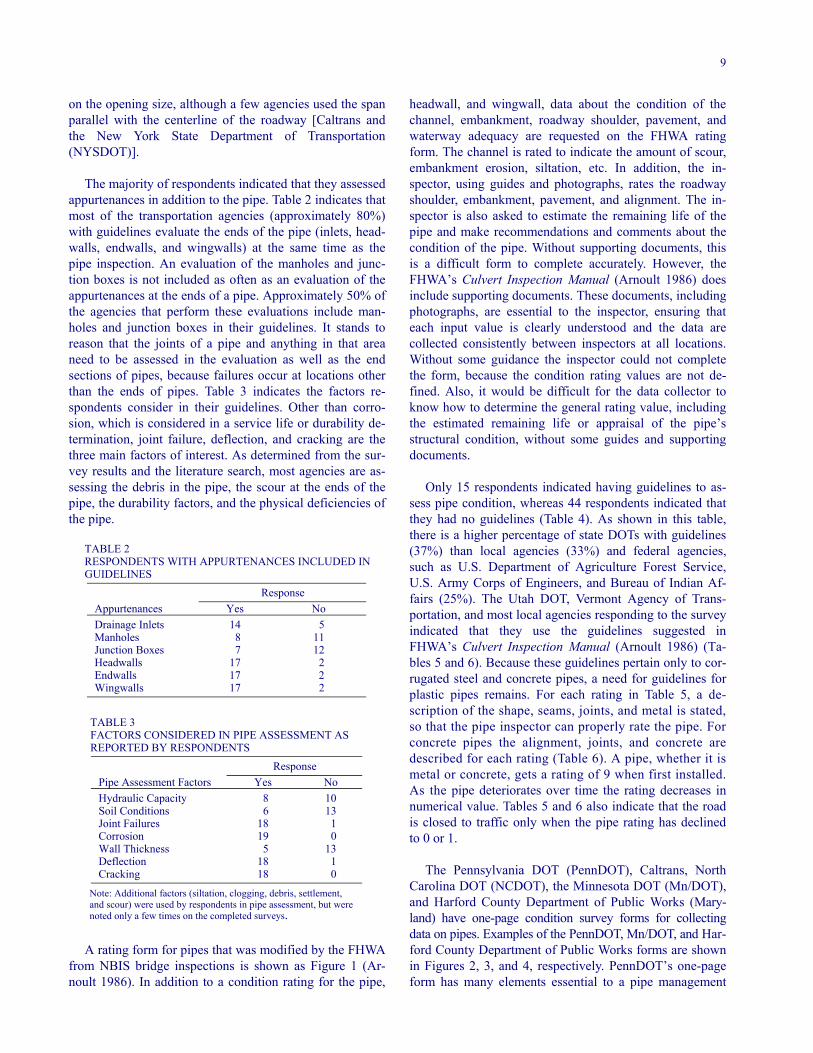
The majority of respondents indicated that they assessedappurtenances in addition to the pipe. Table 2 indicates thatmost of the transportation agencies (approximately 80%)with guidelines evaluate the ends of the pipe (inlets, head-walls, endwalls, and wingwalls) at the same time as thepipe inspection. An evaluation of the manholes and junc-tion boxes is not included as often as an evaluation of theappurtenances at the ends of a pipe. Approximately 50% ofthe agencies that perform these evaluations include man-holes and junction boxes in their guidelines. It stands toreason that the joints of a pipe and anything in that areaneed to be assessed in the evaluation as well as the endsections of pipes, because failures occur at locations otherthan the ends of pipes. Table 3 indicates the factors re-spondents consider in their guidelines. Other than corro-sion, which is considered in a service life or durability de-termination, joint failure, deflection, and cracking are thethree main factors of interest. As determined from the sur-vey results and the literature search, most agencies are as-sessing the debris in the pipe, the scour at the ends of thepipe, the durability factors, and the physical deficiencies ofthe pipe.
TABLE 2RESPONDENTS WITH APPURTENANCES INCLUDED IN GUIDELINES
ResponseAppurtenances Yes NoDrainage Inlets 14 5Manholes 8 11Junction Boxes 7 12Headwalls 17 2Endwalls 17 2Wingwalls 17 2
TABLE 3 FACTORS CONSIDERED IN PIPE ASSESSMENT AS REPORTED BY RESPONDENTS
ResponsePipe Assessment Factors Yes NoHydraulic Capacity 8 10Soil Conditions 6 13Joint Failures 18 1Corrosion 19 0Wall Thickness 5 13Deflection 18 1Cracking 18 0
Note: Additional factors (siltation, clogging, debris, settlement, and scour) were used by respondents in pipe assessment, but were noted only a few times on the completed surveys.
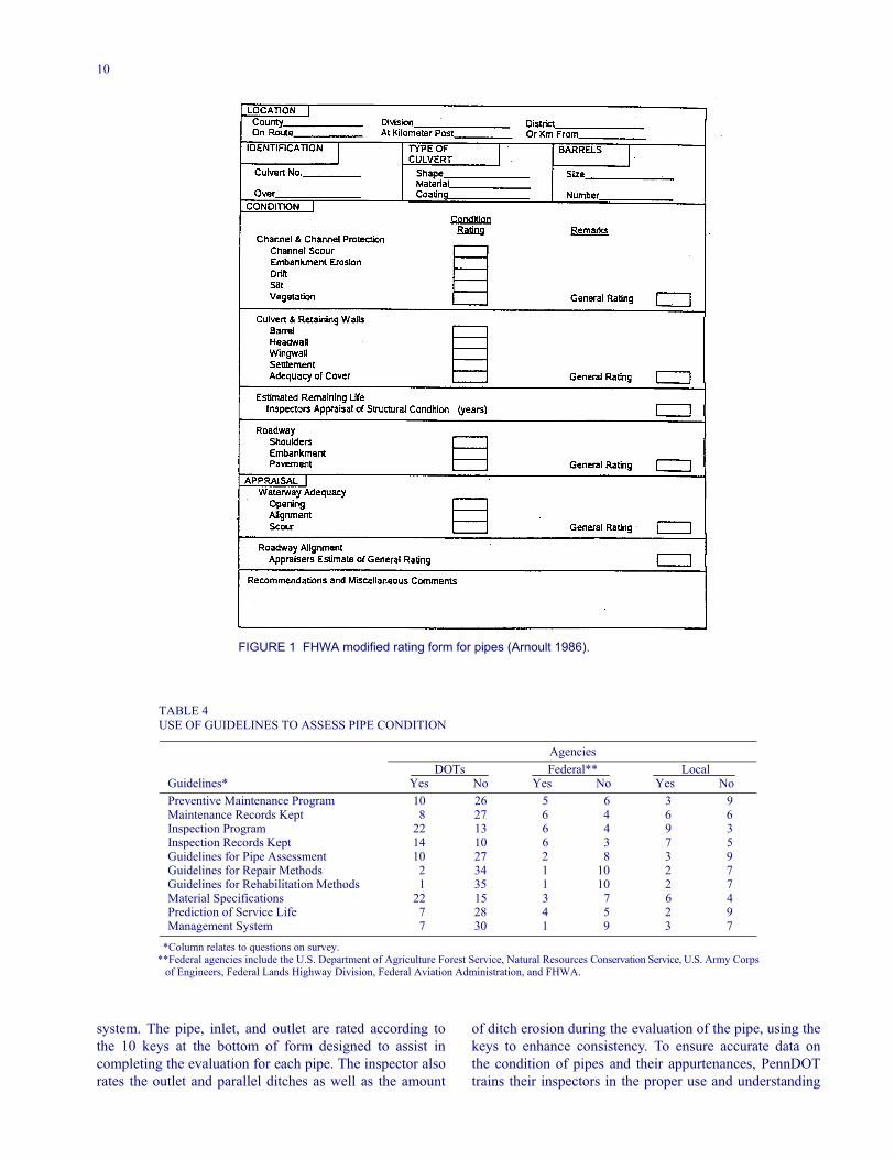
A rating form for pipes that was modified by the FHWAfrom NBIS bridge inspections is shown as Figure 1 (Ar-noult 1986). In addition to a condition rating for the pipe,
headwall, and wingwall, data about the condition of thechannel, embankment, roadway shoulder, pavement, andwaterway adequacy are requested on the FHWA ratingform. The channel is rated to indicate the amount of scour,embankment erosion, siltation, etc. In addition, the in-spector, using guides and photographs, rates the roadwayshoulder, embankment, pavement, and alignment. The in-spector is also asked to estimate the remaining life of thepipe and make recommendations and comments about thecondition of the pipe. Without supporting documents, thisis a difficult form to complete accurately. However, theFHWA’s Culvert Inspection Manual (Arnoult 1986) doesinclude supporting documents. These documents, includingphotographs, are essential to the inspector, ensuring thateach input value is clearly understood and the data arecollected consistently between inspectors at all locations.Without some guidance the inspector could not completethe form, because the condition rating values are not de-fined. Also, it would be difficult for the data collector toknow how to determine the general rating value, includingthe estimated remaining life or appraisal of the pipe’sstructural condition, without some guides and supportingdocuments.
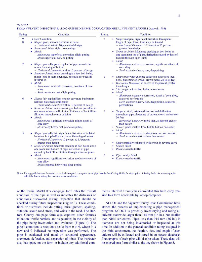
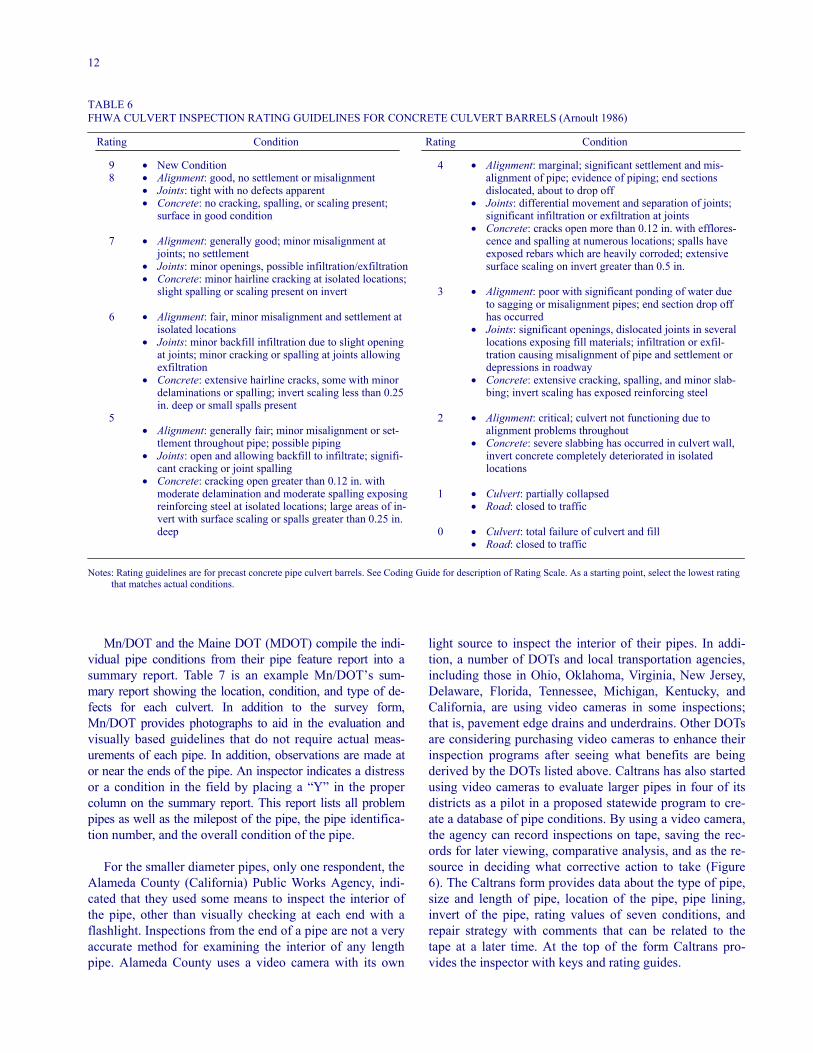
Only 15 respondents indicated having guidelines to as-sess pipe condition, whereas 44 respondents indicated thatthey had no guidelines (Table 4). As shown in this table,there is a higher percentage of state DOTs with guidelines(37%) than local agencies (33%) and federal agencies,such as U.S. Department of Agriculture Forest Service,U.S. Army Corps of Engineers, and Bureau of Indian Af-fairs (25%). The Utah DOT, Vermont Agency of Trans-portation, and most local agencies responding to the surveyindicated that they use the guidelines suggested inFHWA’s Culvert Inspection Manual (Arnoult 1986) (Ta-bles 5 and 6). Because these guidelines pertain only to cor-rugated steel and concrete pipes, a need for guidelines forplastic pipes remains. For each rating in Table 5, a de-scription of the shape, seams, joints, and metal is stated,so that the pipe inspector can properly rate the pipe. Forconcrete pipes the alignment, joints, and concrete aredescribed for each rating (Table 6). A pipe, whether it ismetal or concrete, gets a rating of 9 when first installed.As the pipe deteriorates over time the rating decreases innumerical value. Tables 5 and 6 also indicate that the roadis closed to traffic only when the pipe rating has declinedto 0 or 1.
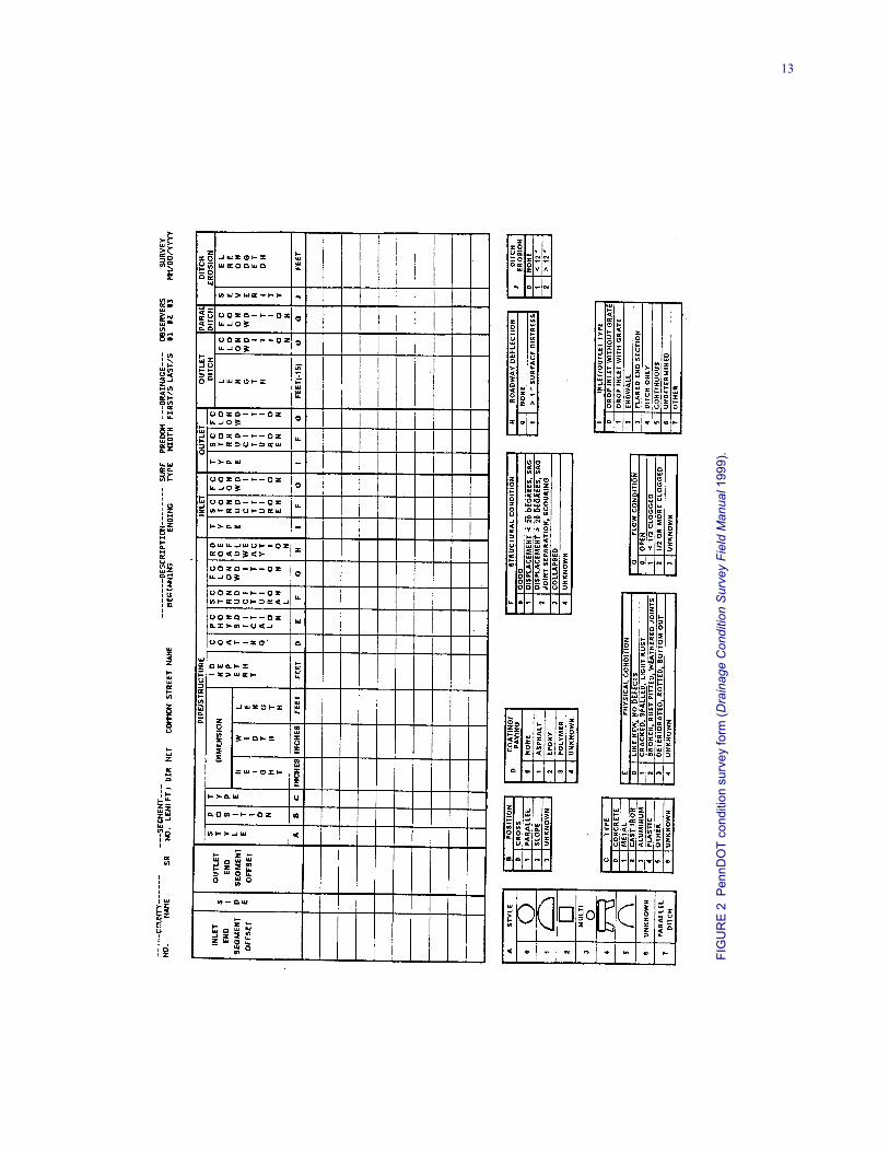
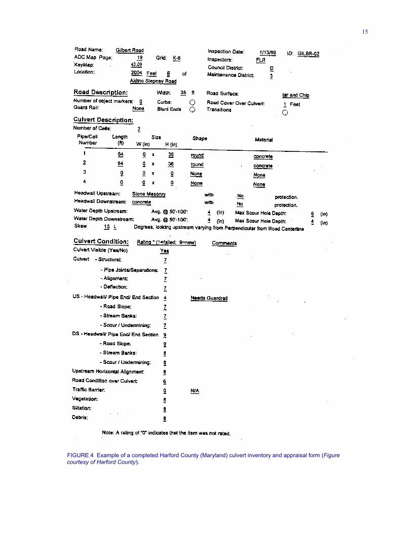
The Pennsylvania DOT (PennDOT), Caltrans, NorthCarolina DOT (NCDOT), the Minnesota DOT (Mn/DOT),and Harford County Department of Public Works (Mary-land) have one-page condition survey forms for collectingdata on pipes. Examples of the PennDOT, Mn/DOT, and Har-ford County Department of Public Works forms are shownin Figures 2, 3, and 4, respectively. PennDOT’s one-pageform has many elements essential to a pipe management
10
FIGURE 1 FHWA modified rating form for pipes (Arnoult 1986).
TABLE 4 USE OF GUIDELINES TO ASSESS PIPE CONDITION
AgenciesDOTs Federal** Local
Guidelines* Yes No Yes No Yes NoPreventive Maintenance Program 10 26 5 6 3 9Maintenance Records Kept 8 27 6 4 6 6Inspection Program 22 13 6 4 9 3Inspection Records Kept 14 10 6 3 7 5Guidelines for Pipe Assessment 10 27 2 8 3 9Guidelines for Repair Methods 2 34 1 10 2 7Guidelines for Rehabilitation Methods 1 35 1 10 2 7Material Specifications 22 15 3 7 6 4Prediction of Service Life 7 28 4 5 2 9Management System 7 30 1 9 3 7
*Column relates to questions on survey. **Federal agencies include the U.S. Department of Agriculture Forest Service, Natural Resources Conservation Service, U.S. Army Corps
of Engineers, Federal Lands Highway Division, Federal Aviation Administration, and FHWA.
system. The pipe, inlet, and outlet are rated according tothe 10 keys at the bottom of form designed to assist incompleting the evaluation for each pipe. The inspector alsorates the outlet and parallel ditches as well as the amount
of ditch erosion during the evaluation of the pipe, using thekeys to enhance consistency. To ensure accurate data onthe condition of pipes and their appurtenances, PennDOTtrains their inspectors in the proper use and understanding
11
TABLE 5FHWA CULVERT INSPECTION RATING GUIDELINES FOR CORRUGATED METAL CULVERT BARRELS (Arnoult 1986)
Rating Condition Rating Condition9 • New Condition 4 • Shape: marginal significant distortion throughout8
7
6
5
• Shape: good, smooth curvature in barrel– Horizontal: within 10 percent of design
• Seams and Joints: tight, no openings• Metal:
– Aluminum: superficial corrosion, slight pitting– Steel: superficial rust, no pitting
• Shape: generally good, top half of pipe smooth butminor flattening of bottom– Horizontal Diameter: within 10 percent of design
• Seams or Joints: minor cracking at a few bolt holes,minor joint or seam openings, potential for backfillinfiltration
• Metal:– Aluminum: moderate corrosion, no attack of core
alloy– Steel: moderate rust, slight pitting
• Shape: fair, top half has smooth curvature but bottomhalf has flattened significantly– Horizontal Diameter: within 10 percent of design
• Seams or Joints: minor cracking at bolts is prevalent inone seam in lower half of pipe. Evidence of backfill in-filtration through seams or joints
• Metal:– Aluminum: significant corrosion, minor attack of
core alloy– Steel: fairly heavy rust, moderate pitting
• Shape: generally fair, significant distortion at isolatedlocations in top half and extreme flattening of invert– Horizontal Diameter: 10 percent to 15 percent
greater than design• Seams or Joints: moderate cracking at bolt holes along
one seam near bottom of pipe, deflection of pipecaused by backfill infiltration through seams or joints
• Metal:– Aluminum: significant corrosion, moderate attack of
core alloy– Steel: scattered heavy rust, deep pitting
3
2
1
0
length of pipe, lower third may be kinked– Horizontal Diameter: 10 percent to 15 percent
greater than design• Seams or Joints: Moderate cracking at bolt holes on
one seam near top of pipe, deflection caused by loss ofbackfill through open joints
• Metal:– Aluminum: extensive corrosion, significant attack of
core alloy– Steel: extensive heavy rust, deep pitting
• Shape: poor with extreme deflection at isolated loca-tions, flattening of crown, crown radius 20 to 30 feet
• Horizontal Diameter: in excess of 15 percent greaterthan design
• 3 in. long cracks at bolt holes on one seam• Metal:
– Aluminum: extensive corrosion, attack of core alloy,scattered perforations
– Steel: extensive heavy rust, deep pitting, scatteredperforations
• Shape: critical, extreme distortion and deflectionthroughout pipe, flattening of crown, crown radius over30 feet– Horizontal Diameter: more than 20 percent greater
than design• Seams: plate cracked from bolt to bolt on one seam• Metal:
– Aluminum: extensive perforations due to corrosion– Steel: extensive perforations due to rust
• Shape: partially collapsed with crown in reverse curve• Seams: failed• Road: closed to traffic
• Pipe: totally failed• Road: closed to traffic
Notes: Rating guidelines are for round or vertical elongated corrugated metal pipe barrels. See Coding Guide for description of Rating Scale. As a starting point, select the lowest rating that matches actual conditions.
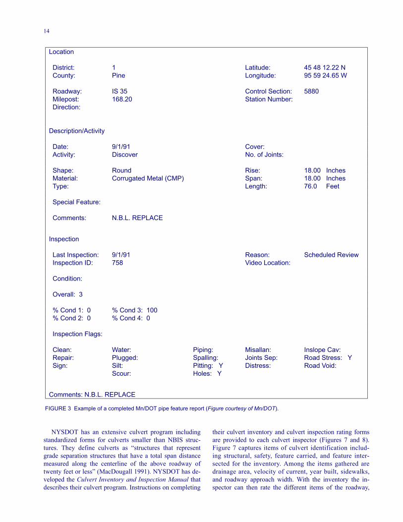
of the forms. Mn/DOT’s one-page form rates the overallcondition of the pipe as well as indicates the distresses orconditions discovered during inspection that should bechecked during future inspections (Figure 3). These condi-tions or distresses include pitting, misalignment, spalling,siltation, scour, road stress, and voids in the road. The Har-ford County one-page form also captures other features(siltation, traffic barriers, and vegetation) in the vicinity ofthe pipe being inventoried and evaluated (Figure 4). Thepipe’s condition is rated on a scale from 0 to 9, where 9 isnew and 0 indicated no inspection was performed. Thepipe is evaluated and rated on structural appearance,alignment, deflection, and separation of joints. The inspectoralso has space on the form to include any additional com-
ments. Harford County has converted this hard copy ver-sion to a form accessible by laptop computer.
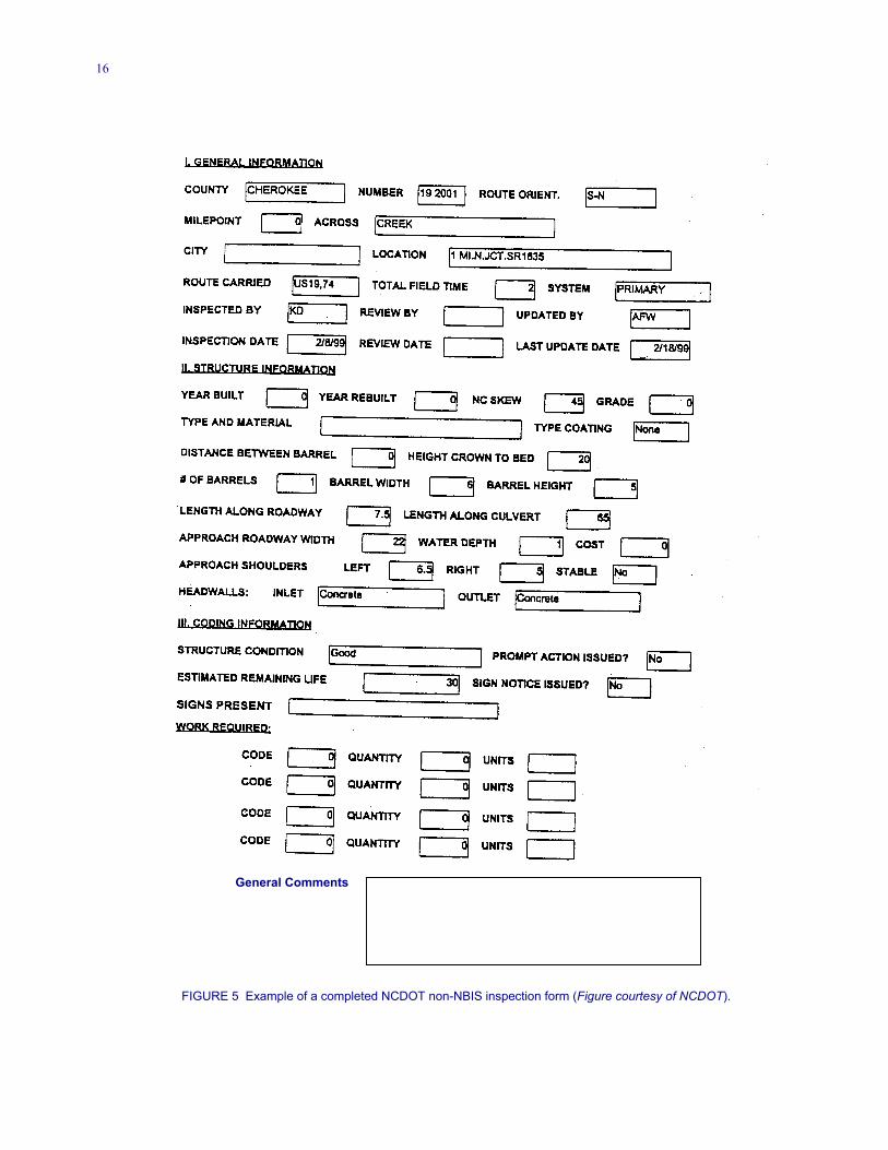
NCDOT and the Saginaw County Road Commission havestarted the process of implementing a pipe managementprogram. NCDOT is presently inventorying and rating allculverts statewide larger than 914 mm (36 in.), but smallerthan NBIS structures. Pipes less than 914 mm (36 in.) indiameter are not being inventoried or inspected at thistime. In addition to the general condition rating assigned inthe initial assessment, the location, size, and length of eachculvert will be collected and stored in an Access database.Photographs of each pipe will also be taken. These data willbe entered on a form similar to the one shown in Figure 5.
12
TABLE 6FHWA CULVERT INSPECTION RATING GUIDELINES FOR CONCRETE CULVERT BARRELS (Arnoult 1986)
Rating Condition Rating Condition
9 • New Condition 4 • Alignment: marginal; significant settlement and mis-8
7
6
5
• Alignment: good, no settlement or misalignment• Joints: tight with no defects apparent• Concrete: no cracking, spalling, or scaling present;
surface in good condition
• Alignment: generally good; minor misalignment atjoints; no settlement
• Joints: minor openings, possible infiltration/exfiltration• Concrete: minor hairline cracking at isolated locations;
slight spalling or scaling present on invert
• Alignment: fair, minor misalignment and settlement atisolated locations
• Joints: minor backfill infiltration due to slight openingat joints; minor cracking or spalling at joints allowingexfiltration
• Concrete: extensive hairline cracks, some with minordelaminations or spalling; invert scaling less than 0.25in. deep or small spalls present
• Alignment: generally fair; minor misalignment or set-tlement throughout pipe; possible piping
• Joints: open and allowing backfill to infiltrate; signifi-cant cracking or joint spalling
• Concrete: cracking open greater than 0.12 in. withmoderate delamination and moderate spalling exposingreinforcing steel at isolated locations; large areas of in-vert with surface scaling or spalls greater than 0.25 in.deep
3
2
1
0
alignment of pipe; evidence of piping; end sections dislocated, about to drop off• Joints: differential movement and separation of joints;
significant infiltration or exfiltration at joints• Concrete: cracks open more than 0.12 in. with efflores-
cence and spalling at numerous locations; spalls haveexposed rebars which are heavily corroded; extensivesurface scaling on invert greater than 0.5 in.
• Alignment: poor with significant ponding of water dueto sagging or misalignment pipes; end section drop offhas occurred
• Joints: significant openings, dislocated joints in severallocations exposing fill materials; infiltration or exfil-tration causing misalignment of pipe and settlement ordepressions in roadway
• Concrete: extensive cracking, spalling, and minor slab-bing; invert scaling has exposed reinforcing steel
• Alignment: critical; culvert not functioning due toalignment problems throughout
• Concrete: severe slabbing has occurred in culvert wall,invert concrete completely deteriorated in isolatedlocations
• Culvert: partially collapsed• Road: closed to traffic
• Culvert: total failure of culvert and fill• Road: closed to traffic
Notes: Rating guidelines are for precast concrete pipe culvert barrels. See Coding Guide for description of Rating Scale. As a starting point, select the lowest rating that matches actual conditions.
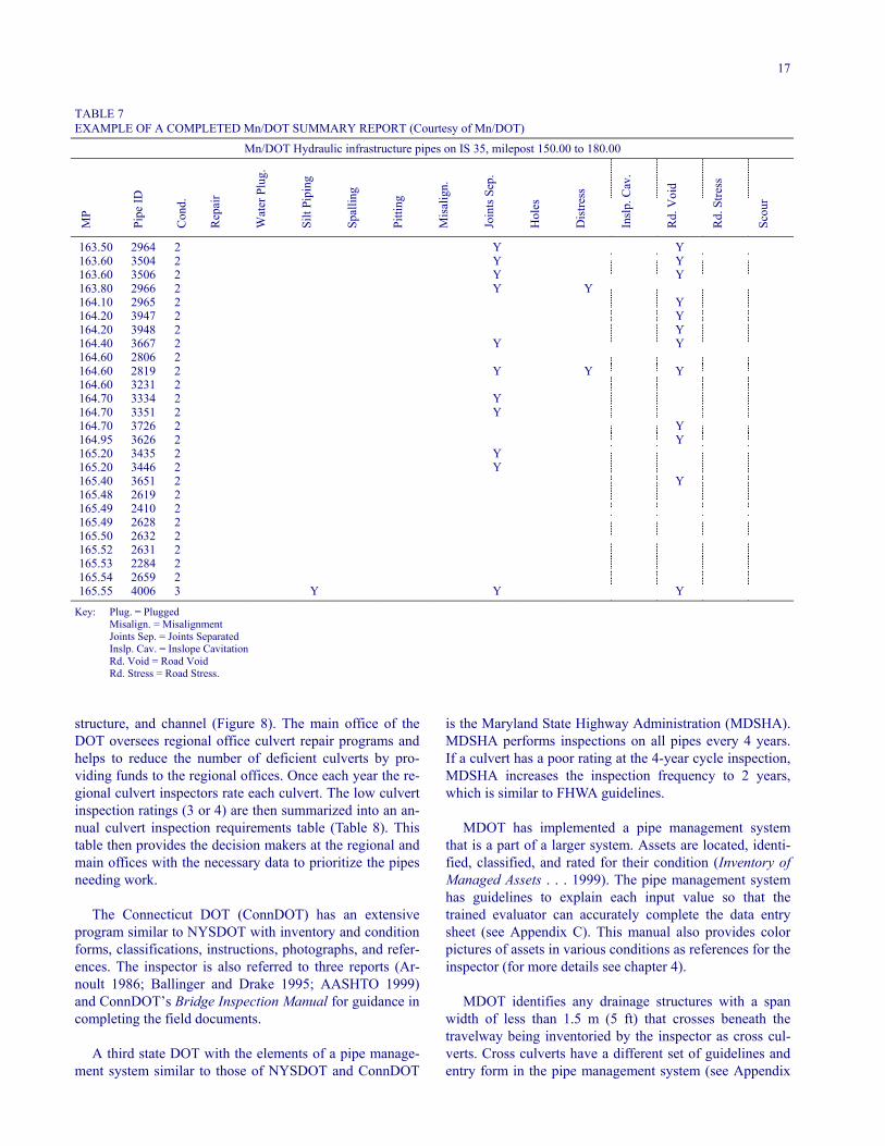
Mn/DOT and the Maine DOT (MDOT) compile the indi-vidual pipe conditions from their pipe feature report into asummary report. Table 7 is an example Mn/DOT’s sum-mary report showing the location, condition, and type of de-fects for each culvert. In addition to the survey form,Mn/DOT provides photographs to aid in the evaluation andvisually based guidelines that do not require actual meas-urements of each pipe. In addition, observations are made ator near the ends of the pipe. An inspector indicates a distressor a condition in the field by placing a “Y” in the propercolumn on the summary report. This report lists all problempipes as well as the milepost of the pipe, the pipe identifica-tion number, and the overall condition of the pipe.
For the smaller diameter pipes, only one respondent, theAlameda County (California) Public Works Agency, indi-cated that they used some means to inspect the interior ofthe pipe, other than visually checking at each end with aflashlight. Inspections from the end of a pipe are not a veryaccurate method for examining the interior of any lengthpipe. Alameda County uses a video camera with its own
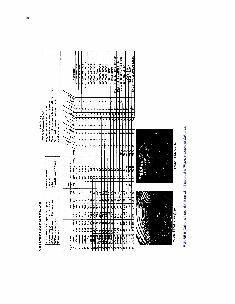
light source to inspect the interior of their pipes. In addi-tion, a number of DOTs and local transportation agencies,including those in Ohio, Oklahoma, Virginia, New Jersey,Delaware, Florida, Tennessee, Michigan, Kentucky, andCalifornia, are using video cameras in some inspections;that is, pavement edge drains and underdrains. Other DOTsare considering purchasing video cameras to enhance theirinspection programs after seeing what benefits are beingderived by the DOTs listed above. Caltrans has also startedusing video cameras to evaluate larger pipes in four of itsdistricts as a pilot in a proposed statewide program to cre-ate a database of pipe conditions. By using a video camera,the agency can record inspections on tape, saving the rec-ords for later viewing, comparative analysis, and as the re-source in deciding what corrective action to take (Figure6). The Caltrans form provides data about the type of pipe,size and length of pipe, location of the pipe, pipe lining,invert of the pipe, rating values of seven conditions, andrepair strategy with comments that can be related to thetape at a later time. At the top of the form Caltrans pro-vides the inspector with keys and rating guides.
13
FIG
UR
E 2
Penn
DO
T co
nditi
on s
urve
y fo
rm (D
rain
age
Con
ditio
n Su
rvey
Fie
ld M
anua
l 199
9).
14
Location
District: 1 Latitude: 45 48 12.22 N County: Pine Longitude: 95 59 24.65 W
Roadway: IS 35 Control Section: 5880 Milepost: 168.20 Station Number: Direction:
Description/Activity
Date: 9/1/91 Cover: Activity: Discover No. of Joints:
Shape: Round Rise: 18.00 Inches Material: Corrugated Metal (CMP) Span: 18.00 Inches Type: Length: 76.0 Feet
Special Feature:
Comments: N.B.L. REPLACE
Inspection
Last Inspection: 9/1/91 Reason: Scheduled Review Inspection ID: 758 Video Location:
Condition:
Overall: 3
% Cond 1: 0 % Cond 3: 100 % Cond 2: 0 % Cond 4: 0
Inspection Flags:
Clean: Water: Piping: Misallan: Inslope Cav: Repair: Plugged: Spalling: Joints Sep: Road Stress: Y Sign: Silt: Pitting: Y Distress: Road Void:
Scour: Holes: Y
Comments: N.B.L. REPLACE
FIGURE 3 Example of a completed Mn/DOT pipe feature report (Figure courtesy of Mn/DOT).
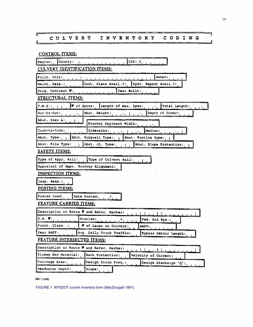
NYSDOT has an extensive culvert program includingstandardized forms for culverts smaller than NBIS struc-tures. They define culverts as “structures that representgrade separation structures that have a total span distancemeasured along the centerline of the above roadway oftwenty feet or less” (MacDougall 1991). NYSDOT has de-veloped the Culvert Inventory and Inspection Manual thatdescribes their culvert program. Instructions on completing
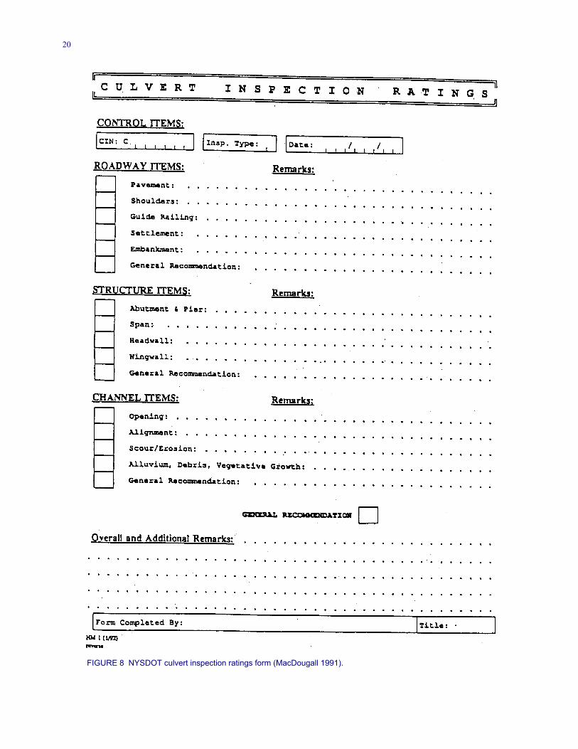
their culvert inventory and culvert inspection rating formsare provided to each culvert inspector (Figures 7 and 8).Figure 7 captures items of culvert identification includ-ing structural, safety, feature carried, and feature inter-sected for the inventory. Among the items gathered aredrainage area, velocity of current, year built, sidewalks,and roadway approach width. With the inventory the in-spector can then rate the different items of the roadway,
15
FIGURE 4 Example of a completed Harford County (Maryland) culvert inventory and appraisal form (Figure courtesy of Harford County).
16
General Comments
FIGURE 5 Example of a completed NCDOT non-NBIS inspection form (Figure courtesy of NCDOT).
17
TABLE 7EXAMPLE OF A COMPLETED Mn/DOT SUMMARY REPORT (Courtesy of Mn/DOT)
Mn/DOT Hydraulic infrastructure pipes on IS 35, milepost 150.00 to 180.00
MP
Pipe
ID
Con
d.
Rep
air
Wat
er P
lug.
Silt
Pipi
ng
Spal
ling
Pitti
ng
Mis
alig
n.
Join
ts S
ep.
Hol
es
Dis
tress
Insl
p. C
av.
Rd.
Voi
d
Rd.
Stre
ss
Scou
r
163.50 2964 2 Y Y163.60 3504 2 Y Y163.60 3506 2 Y Y163.80 2966 2 Y Y164.10 2965 2 Y164.20 3947 2 Y164.20 3948 2 Y164.40 3667 2 Y Y164.60 2806 2164.60 2819 2 Y Y Y164.60 3231 2164.70 3334 2 Y164.70 3351 2 Y164.70 3726 2 Y164.95 3626 2 Y165.20 3435 2 Y165.20 3446 2 Y165.40 3651 2 Y165.48 2619 2165.49 2410 2165.49 2628 2165.50 2632 2165.52 2631 2165.53 2284 2165.54 2659 2165.55 4006 3 Y Y Y
Key: Plug. = PluggedMisalign. = MisalignmentJoints Sep. = Joints SeparatedInslp. Cav. = Inslope CavitationRd. Void = Road VoidRd. Stress = Road Stress.
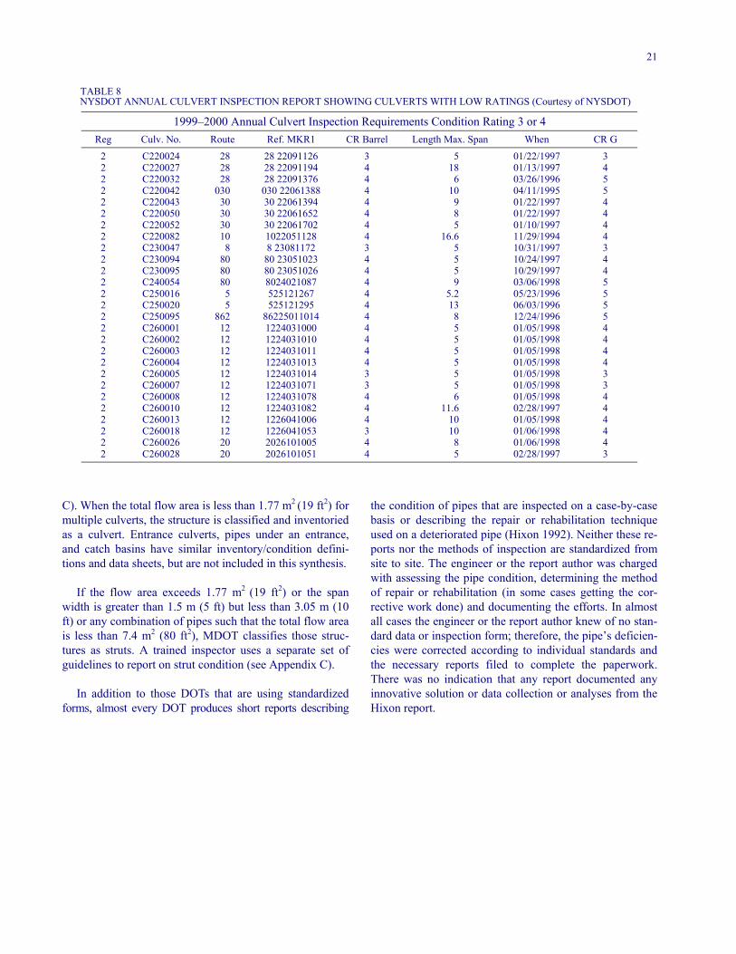
structure, and channel (Figure 8). The main office of theDOT oversees regional office culvert repair programs andhelps to reduce the number of deficient culverts by pro-viding funds to the regional offices. Once each year the re-gional culvert inspectors rate each culvert. The low culvertinspection ratings (3 or 4) are then summarized into an an-nual culvert inspection requirements table (Table 8). Thistable then provides the decision makers at the regional andmain offices with the necessary data to prioritize the pipesneeding work.
The Connecticut DOT (ConnDOT) has an extensiveprogram similar to NYSDOT with inventory and conditionforms, classifications, instructions, photographs, and refer-ences. The inspector is also referred to three reports (Ar-noult 1986; Ballinger and Drake 1995; AASHTO 1999)and ConnDOT’s Bridge Inspection Manual for guidance incompleting the field documents.
A third state DOT with the elements of a pipe manage-ment system similar to those of NYSDOT and ConnDOT
is the Maryland State Highway Administration (MDSHA).MDSHA performs inspections on all pipes every 4 years.If a culvert has a poor rating at the 4-year cycle inspection,MDSHA increases the inspection frequency to 2 years,which is similar to FHWA guidelines.
MDOT has implemented a pipe management systemthat is a part of a larger system. Assets are located, identi-fied, classified, and rated for their condition (Inventory ofManaged Assets . . . 1999). The pipe management systemhas guidelines to explain each input value so that thetrained evaluator can accurately complete the data entrysheet (see Appendix C). This manual also provides colorpictures of assets in various conditions as references for theinspector (for more details see chapter 4).
MDOT identifies any drainage structures with a spanwidth of less than 1.5 m (5 ft) that crosses beneath thetravelway being inventoried by the inspector as cross cul-verts. Cross culverts have a different set of guidelines andentry form in the pipe management system (see Appendix
18
FIG
UR
E 6 C
altra
ns in
spec
tion
form
with
pho
togr
aphs
(Fig
ure
cour
tesy
of C
altra
ns).
19
FIGURE 7 NYSDOT culvert inventory form (MacDougall 1991).
20
FIGURE 8 NYSDOT culvert inspection ratings form (MacDougall 1991).
21
TABLE 8 NYSDOT ANNUAL CULVERT INSPECTION REPORT SHOWING CULVERTS WITH LOW RATINGS (Courtesy of NYSDOT)
1999–2000 Annual Culvert Inspection Requirements Condition Rating 3 or 4Reg Culv. No. Route Ref. MKR1 CR Barrel Length Max. Span When CR G
2 C220024 28 28 22091126 3 5 01/22/1997 32 C220027 28 28 22091194 4 18 01/13/1997 42 C220032 28 28 22091376 4 6 03/26/1996 52 C220042 030 030 22061388 4 10 04/11/1995 52 C220043 30 30 22061394 4 9 01/22/1997 42 C220050 30 30 22061652 4 8 01/22/1997 42 C220052 30 30 22061702 4 5 01/10/1997 42 C220082 10 1022051128 4 16.6 11/29/1994 42 C230047 8 8 23081172 3 5 10/31/1997 32 C230094 80 80 23051023 4 5 10/24/1997 42 C230095 80 80 23051026 4 5 10/29/1997 42 C240054 80 8024021087 4 9 03/06/1998 52 C250016 5 525121267 4 5.2 05/23/1996 52 C250020 5 525121295 4 13 06/03/1996 52 C250095 862 86225011014 4 8 12/24/1996 52 C260001 12 1224031000 4 5 01/05/1998 42 C260002 12 1224031010 4 5 01/05/1998 42 C260003 12 1224031011 4 5 01/05/1998 42 C260004 12 1224031013 4 5 01/05/1998 42 C260005 12 1224031014 3 5 01/05/1998 32 C260007 12 1224031071 3 5 01/05/1998 32 C260008 12 1224031078 4 6 01/05/1998 42 C260010 12 1224031082 4 11.6 02/28/1997 42 C260013 12 1226041006 4 10 01/05/1998 42 C260018 12 1226041053 3 10 01/06/1998 42 C260026 20 2026101005 4 8 01/06/1998 42 C260028 20 2026101051 4 5 02/28/1997 3
C). When the total flow area is less than 1.77 m2 (19 ft2) formultiple culverts, the structure is classified and inventoriedas a culvert. Entrance culverts, pipes under an entrance,and catch basins have similar inventory/condition defini-tions and data sheets, but are not included in this synthesis.
If the flow area exceeds 1.77 m2 (19 ft2) or the spanwidth is greater than 1.5 m (5 ft) but less than 3.05 m (10ft) or any combination of pipes such that the total flow areais less than 7.4 m2 (80 ft2), MDOT classifies those struc-tures as struts. A trained inspector uses a separate set ofguidelines to report on strut condition (see Appendix C).
In addition to those DOTs that are using standardizedforms, almost every DOT produces short reports describing
the condition of pipes that are inspected on a case-by-casebasis or describing the repair or rehabilitation techniqueused on a deteriorated pipe (Hixon 1992). Neither these re-ports nor the methods of inspection are standardized fromsite to site. The engineer or the report author was chargedwith assessing the pipe condition, determining the methodof repair or rehabilitation (in some cases getting the cor-rective work done) and documenting the efforts. In almostall cases the engineer or the report author knew of no stan-dard data or inspection form; therefore, the pipe’s deficien-cies were corrected according to individual standards andthe necessary reports filed to complete the paperwork.There was no indication that any report documented anyinnovative solution or data collection or analyses from theHixon report.
22
CHAPTER THREE
METHODS TO SELECT PIPE REPAIR AND REHABILITATION
PIPE REPAIR
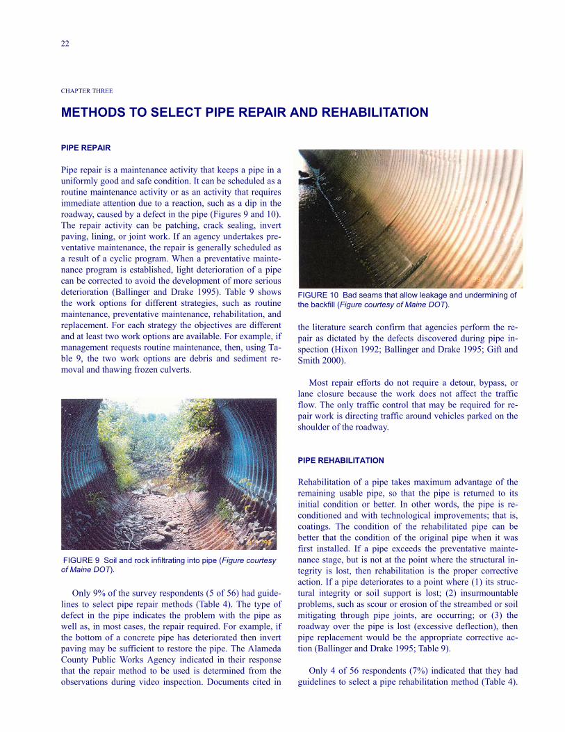
Pipe repair is a maintenance activity that keeps a pipe in auniformly good and safe condition. It can be scheduled as aroutine maintenance activity or as an activity that requiresimmediate attention due to a reaction, such as a dip in theroadway, caused by a defect in the pipe (Figures 9 and 10).The repair activity can be patching, crack sealing, invertpaving, lining, or joint work. If an agency undertakes pre-ventative maintenance, the repair is generally scheduled asa result of a cyclic program. When a preventative mainte-nance program is established, light deterioration of a pipecan be corrected to avoid the development of more seriousdeterioration (Ballinger and Drake 1995). Table 9 showsthe work options for different strategies, such as routinemaintenance, preventative maintenance, rehabilitation, andreplacement. For each strategy the objectives are differentand at least two work options are available. For example, ifmanagement requests routine maintenance, then, using Ta-ble 9, the two work options are debris and sediment re-moval and thawing frozen culverts.
FIGURE 9 Soil and rock infiltrating into pipe (Figure courtesyof Maine DOT).
Only 9% of the survey respondents (5 of 56) had guide-lines to select pipe repair methods (Table 4). The type ofdefect in the pipe indicates the problem with the pipe aswell as, in most cases, the repair required. For example, ifthe bottom of a concrete pipe has deteriorated then invertpaving may be sufficient to restore the pipe. The AlamedaCounty Public Works Agency indicated in their responsethat the repair method to be used is determined from theobservations during video inspection. Documents cited in
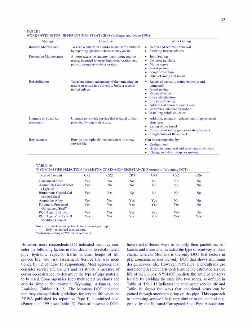
FIGURE 10 Bad seams that allow leakage and undermining ofthe backfill (Figure courtesy of Maine DOT).
the literature search confirm that agencies perform the re-pair as dictated by the defects discovered during pipe in-spection (Hixon 1992; Ballinger and Drake 1995; Gift andSmith 2000).
Most repair efforts do not require a detour, bypass, orlane closure because the work does not affect the trafficflow. The only traffic control that may be required for re-pair work is directing traffic around vehicles parked on theshoulder of the roadway.
PIPE REHABILITATION
Rehabilitation of a pipe takes maximum advantage of theremaining usable pipe, so that the pipe is returned to itsinitial condition or better. In other words, the pipe is re-conditioned and with technological improvements; that is,coatings. The condition of the rehabilitated pipe can bebetter that the condition of the original pipe when it wasfirst installed. If a pipe exceeds the preventative mainte-nance stage, but is not at the point where the structural in-tegrity is lost, then rehabilitation is the proper correctiveaction. If a pipe deteriorates to a point where (1) its struc-tural integrity or soil support is lost; (2) insurmountableproblems, such as scour or erosion of the streambed or soilmitigating through pipe joints, are occurring; or (3) theroadway over the pipe is lost (excessive deflection), thenpipe replacement would be the appropriate corrective ac-tion (Ballinger and Drake 1995; Table 9).
Only 4 of 56 respondents (7%) indicated that they hadguidelines to select a pipe rehabilitation method (Table 4).
23
TABLE 9 WORK OPTIONS FOR DIFFERENT PIPE STRATEGIES (Ballinger and Drake 1995)
Strategy Objective Work Options
Routine Maintenance To keep a culvert in a uniform and safe conditionby repairing specific defects as they occur.
• Debris and sediment removal• Thawing frozen culverts
Preventive Maintenance A more extensive strategy than routine mainte-nance, intended to arrest light deterioration andprevent progressive deterioration.
• Joint Sealing• Concrete patching• Mortar repair• Invert paving• Scour prevention• Ditch cleaning and repair
Rehabilitation Takes maximum advantage of the remaining un-usable structure in a culvert to build a recondi-tioned culvert.
• Repair of basically sound endwalls andwingwalls
• Invert paving• Repair of scour• Slope stabilization• Streambed paving• Addition of apron or cutoff wall• Improving inlet configuration• Installing debris collector
Upgrade to Equal Re-placement
Upgrade to provide service that is equal to thatprovided by a new structure.
• Addition, repair, or replacement of appurtenantstructures
• Lining of the barrel• Provision of safety grates or safety barriers• Lengthening of the culvert
Replacement Provide a completely new culvert with a newservice life.
Can be accompanied by:• Realignment• Hydraulic structural and safety improvements• Change in culvert shape or material
TABLE 10WYOMING PIPE SELECTION TABLE FOR CORROSION RESISTANCE (Courtesy of Wyoming DOT)
Type of Conduit CR1 CR2 CR3 CR4 CR5 CR6
Galvanized Steel Yes No No No No NoAluminum Coated Steel
(Type II)Yes No No No No No
Bituminous Coated Gal-vanized Steel
Yes Yes No No No No
Aluminum Alloy Yes Yes Yes Yes No NoPolymeric Precoated
Galvanized Steel*Yes Yes Yes Yes Yes No
RCP Type II Cement Yes Yes Yes Yes Yes NoRCP Type V or Type II
Modified CementYes Yes Yes Yes Yes Yes
Notes: This table is not applicable for structural plate pipe.RCP = reinforced concrete pipe.
*Polymeric coating of 250 µm on both sides.
However, more respondents (15) indicated that they con-sider the following factors in their decision to rehabilitate apipe: hydraulic capacity, traffic volume, height of fill,service life, and risk assessment. Service life was men-tioned by 12 of these 15 respondents. Most agencies thatconsider service life use pH and resistivity, a measure ofcorrosion resistance, to determine the type of pipe materialto be used. Some agencies keep their selection charts andcriteria simple; for example, Wyoming, Arkansas, andLouisiana (Tables 10–12). The Montana DOT indicatedthat they changed their guidelines for service life when theFHWA published its report on Type II aluminized steel(Potter et al. 1991; see Table 13). Each of these state DOTs
have tried different ways to simplify their guidelines. Ar-kansas and Louisiana included the type of roadway in theircharts, whereas Montana is the only DOT that factors inpH. Louisiana is also the only DOT that shows minimumdesign service life. However, NYSDOT and Caltrans usemore complicated charts to determine the estimated servicelife of their pipes. NYSDOT predicts the anticipated serv-ice life by dividing the state into two zones, as defined inTable 14. Table 15 indicates the anticipated service life andTable 16 shows the ways that additional years can begained through another coating on the pipe. This approachto increasing service life is very similar to the method sug-gested by the National Corrugated Steel Pipe Association.
24
TABLE 11 ARKANSAS PIPE CHART CORRELATING FACILITY AND MATERIAL TYPES TO PIPE FUNCTION (Courtesy of Arkansas DOT)
Type Facility Pipe Function Material Type
Interstate Cross drain ConcreteStorm sewer Concrete
Arterial Cross drain ConcreteStorm sewer Concrete or smooth-lined
polymer-coated CSPCollector and Local Cross drain
Storm sewer
Concreteasphalt-coated CSP,
aluminum-coated CSP, orpolymer-coated CSP
Concrete or smooth-linedpolymer-coated CSP
City Street* Cross drain
Storm sewer
Concrete orpolymer-coated CSP
Concrete or smooth-linedpolymer-coated CSP
All Side drain Refer to current specifications,section 606
Note: CSP = corrugated steel pipe. *The city administration may select the type of culverts to be used on city streets in accordance with normal city
policy.
Caltrans designs its pipes for a maintenance-free servicelife of 50 years using charts shown as Figures F1 and F2,and using Figure F3 as a guide to increasing the service lifeby applying different coatings to steel pipes (Appendix F).
Service life was factored into the decision process by 13of 55 responding agencies (24%) (Table 4). Most agenciesindicated that they use service-life data provided by themanufacturers. Service life is generally considered whenmetal pipes are used and a new pipe is inserted into the old,deteriorated pipe or the deteriorated pipe is replaced. Occa-sionally service life is a factor with concrete pipe (Utah DOT),but rarely with plastic pipe. The Nebraska Department ofRoads indicated that they use the Caltrans method to pre-dict the service life of their culverts. The two local agen-cies responding positively to the service-life questions in-dicated that they use their state DOT’s service-lifeprocedures.
Table 17 indicates the permanent methods of structuralstabilization reported by the agencies responding to thequestionnaire. Lining of the pipe is the method of stabili-zation preferred by most agencies (Figure 11). From theliterature search, the most reported method of permanentstructural stabilization is also lining. From the survey itwas determined that cut-and-cover and invert paving areequally as popular, but are not the preferred method of sta-bilization of a deteriorated pipe (Figure 12). From the lit-erature it was indicated that where states have been facedwith insufficient funds to perform major or deep excava-tions, the roadway is paved, or the traffic volume is high,they have used invert replacement, insertion of a pipe in-
side the deteriorating pipe, or installation of some kind oflining to avoid cut and cover.
Ikerd (1984) reported on the use of invert replacementby the Alabama DOT, where a corrugated metal structuralplate pipe was at the bottom of a 41-m (135-ft) fill (Figure12). Also, Duncan (1984) reported that Montana insertedan asphalt-coated pipe into a deteriorating structural steelplate pipe arch culvert. Meanwhile, in 1985, the FHWAevaluated various repair methods under the ExperimentalProjects Program to determine the best method to reha-bilitate pipes on the Skyline Drive in Virginia (Beucler1985). They concluded that the inverted-resin impregnatefelt tube process was the method that should be used to re-habilitate these 50-year-old pipes. Sukley and St. John(1994) reported on the performance of the polyester fiber-felt, thermosetting resins, and polyurethane pipe rehabili-tation process used on a PennDOT project over a 9-yearstudy period. The “pipe in a pipe” performed satisfactorilyand saved PennDOT an estimated $170,000. In addition,the liner improved the flow in the pipe and required littleexcavation.
In 1997, Okpala and Anderson reported that sliplinerswere cost-beneficial when compared with excavating andreplacing a deteriorating pipe. At one site they indicatedthat a 52% savings was achieved over the estimated cost ofexcavating and replacing. In conclusion, they reported thatcost savings will be greater as the depth of the pipe in-creased, traffic delays increased, and other interruptions tothe traveling public, such as detours, are factored into theanalysis.
25
TABLE 12 LOUISIANA PIPE SELECTION TABLE (Courtesy of Louisiana DOT)
EDSM NO. II.2.1.1
Design Service Life and Material Selection for Culverts and Storm Drains (3)
Application Materials (Type Joints) (1) Minimum Design Service Life
1. Storm drains, flumes, and other watertight systems
RCP(A)(T3), RCB, PRCB(T3),RPVCCP(T3), RPECP(T3)
70 years
2. Cross drains for: freeways F-1, F-2, F-3 urban arterial UA-1, UA-2 rural arterial RA-1, RA-2, RA-3, RA-4 urban collector (4 lanes) RC-3
RCP(A)(T3), RCB, PRCB(T3),RPVCCP(T3), RPECP(T3)
70 years
3. Cross drains for: urban collector (2 lanes) UC-1, UC-2, UC-3 rural collector (2 lanes) RC-1, RC-2, RC-3 urban local UL-1, UL-2 rural local RL-1, RL-2, RL-3
RCP(A)(T2), RCB, PRCB(T2),RPVCCP(T2), RPECP(T2),
PCCSP(A)(T2), BCCSP(A)(T2),CAP(A)(T2)
50 years
4. Side drains Same as 3 except Type 1 joints(T1)and
Add CPECP(T1), CSP(A)(T1),PVCCP(T1)
30 years
5. Underdrains Perforated Pipe Underdrains (see Specifi-cations)
(2)
6. Special installations RPVCCP, RPECP, PCCSP(A),BCCSP(A), CAP(A), CPEC
See Section B
Notes: (1) When design requirements make the use of pipe arch necessary, the specified materials and type joints will be used.(2) Same as drains with 50-year design life.(3) Other alternates, when approved, will be added by revising this EDSM.(4) (A) designates arch option.
Material Type Abbreviations and Definitions:RCP = reinforced concrete pipe; RCPA = reinforced concrete pipe arch; RCB = reinforced concrete box culvert; PRCB = precast reinforcedconcrete box culvert; CAP = corrugated aluminum pipe; CAPA = corrugated aluminum pipe arch; CSP = corrugated galvanized steel pipe(no coating); CSPA = corrugated galvanized steel pipe arch (no coating); BCCSP = bituminous coated corrugated steel pipe; BCCSPA =bituminous coated corrugated steel pipe arch; PCCSP = polymer coated corrugated steel pipe; PCCSPA = polymer coated corrugated steelpipe arch; RPVCCP = ribbed polyvinyl chloride culvert pipe; PVCCP = polyvinyl chloride culvert pipe (AASHTO M304); CPECP =corrugated polyethylene culvert pipe (AASHTO M294—Type S); RPECP = ribbed polyethylene culvert pipe [ASTM F894—Ring StiffnessConstant (RSC) of 160]; T1 = Type 1 Joints—To be used for side drains culvert pipe. The combination of gasket material and joint toprevent infiltration. (See specifications for more detailed information.) Type 2 or 3 joints may be used; T2 = Type 2 Joints—The combina-tion of gasket material and joint configuration meets the 5 psi hydrostatic pressure test. (See specifications for more detailed information);and T3 = Type 3 Joints—The combination of gasket material and joint configuration meets the 10 psi hydrostatic pressure test. (See speci-fications for more detailed information).
Transportation agencies are also either jacking or boringpipes or lining the deteriorated pipe with polyethylene(Tymkowicz 1995), polyvinylchloride, polypropylene,thermosetting glass-reinforced plastic, cement mortar, orsmooth or corrugated steel pipe. One critical issue with aliner is the thickness of the liner wall. The liner wall needsto be as thin as possible so as to minimize the reduction ofthe cross-sectional area and flow capacity of the pipe. The
liners can be forced through the pipe by pushing (pipejacking) or by being pulled through the pipe (Figures 13and 14). When only a segment or small portion of a pipeneeds to be repaired, a section or two of liner can be in-stalled. A small section of lining is positioned at the dete-riorated area and then jacked against the existing pipe(Figure 15). Another method of lining a pipe is with a ce-ment mortar liner, where the liner is formed from cement
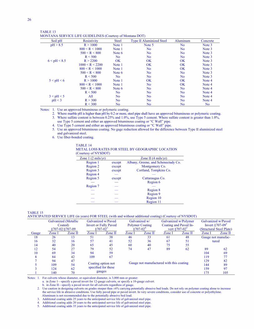
26
TABLE 13 MONTANA SERVICE LIFE GUIDELINES (Courtesy of Montana DOT)
Soil pH Resistivity Steel Type II Aluminized Steel Aluminum ConcretepH > 8.5 R > 1000 Note 1 Note 5 No Note 3
800 < R < 1000 Note 1 No No Note 3500 < R < 800 Note 6 No No Note 3
R < 500 No No No Note 36 < pH < 8.5 R > 2200 OK OK OK Note 3
1000 < R < 2200 Note 1 OK OK Note 3800 < R < 1000 Note 1 No OK Note 3500 < R < 800 Note 6 No No Note 3
R < 500 No No No Note 35 < pH < 6 R > 1000 Note 1 OK OK Note 4
800 < R < 1000 Note 1 No OK Note 4500 < R < 800 Note 6 No No Note 4
R < 500 No No No Note 43 < pH < 5 All No No No Note 4
pH < 3 R > 300 No No No Note 4R < 300 No No No No
Notes: 1. Use an approved bituminous or polymeric coating.2. Where marble pH is higher than pH by 0.2 or more, steel pipe shall have an approved bituminous or polymeric coating. 3. Where sulfate content is between 0.25% and 1.0%, use Type 5 cement. Where sulfate content is greater than 1.0%,
use Type 5 cement and either an approved bituminous coating or “C Wall” pipe.4. Use Type 5 cement and either an approved bituminous coating or “C Wall” pipe.5. Use an approved bituminous coating. No gage reduction allowed for the difference between Type II aluminized steel
and galvanized steel.6. Use fiber-bonded coating.
TABLE 14 METAL LOSS RATES FOR STEEL BY GEOGRAPHIC LOCATION (Courtesy of NYSDOT)
Zone 1 (2 mils/yr) Zone II (4 mils/yr)Region 1 except Albany, Greene, and Schenectady Co.Region 2 except Montgomery Co.Region 3 except Cortland, Tompkins Co.Region 4 — —Region 5 except Cattaraugus Co.
— — Region 6Region 7 — —
— — Region 8— — Region 9— — Region 10— — Region 11
TABLE 15ANTICIPATED SERVICE LIFE (in years) FOR STEEL (with and without additional coating) (Courtesy of NYSDOT)
Galvanized (MetallicCoated)
§707-02/§707-09
Galvanized w/PavedInvert or Fully Paved
§707-023
Galvanized w/Polymer Coating
§707-024
Galvanized w/PolymerCoating and Paved In-
vert §707-025
Galvanized w/PavedInvert §707-095
(Structural Steel Plate)Gauge Zone I Zone II Zone I Zone II Zone I Zone II Zone I Zone II Zone I Zone II
18 26 13 51 38 46 33 61 4816 32 16 57 41 52 36 67 5114 40 20 65 45 60 40 75 55
Gauge not manufac-tured
12 54 27 79 52 74 47 89 62 89 6210 69 34 94 59 104 698 84 42 109 67 119 777 94 47 129 825 109 54 144 893 124 62 159 971 140 70
Coating option notspecified for these
gauges
Gauge not manufactured with this coating
175 105Notes: 1. For culverts whose diameter, or equivalent diameter, is 3,000 mm or greater:
a. in Zone 1—specify a paved invert for 12-gauge culverts, or specify a 10-gauge culvert.b. in Zone II—specify a paved invert for all culverts regardless of gauge.
2. Use caution in designing culverts on grades steeper than ±6% carrying potentially abrasive bed loads. Do not rely on polymer coating alone to increasethe service life in abrasive conditions. Use fully paved pipe or paved invert. In very severe conditions, consider use of concrete or polyethylene.
Aluminum is not recommended due to the potentially abrasive bed load.3. Additional coating adds 25 years to the anticipated service life of galvanized steel pipe.4. Additional coating adds 20 years to the anticipated service life of galvanized steel pipe.5. Additional coating adds 35 years to the anticipated service life of galvanized steel pipe.
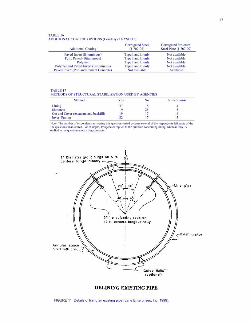
27
TABLE 16 ADDITIONAL COATING OPTIONS (Courtesy of NYSDOT)
Additional CoatingCorrugated Steel
(§ 707-02)Corrugated StructuralSteel Plate (§ 707-09)
Paved Invert (Bituminous) Type I and II only Not availableFully Paved (Bituminous) Type I and II only Not available
Polymer Type I and II only Not availablePolymer and Paved Invert (Bituminous) Type I and II only Not available
Paved Invert (Portland Cement Concrete) Not available Available
TABLE 17METHODS OF STRUCTURAL STABILIZATION USED BY AGENCIES
Method Yes No No Response
Lining 37 8 4Shotcrete 9 25 5Cut and Cover (excavate and backfill) 19 17 4Invert Paving 22 17 3
Note: The number of respondents answering this question varied because several of the respondents left some of thethe questions unanswered. For example, 49 agencies replied to the question concerning lining, whereas only 39
replied to the question about using shotcrete.
FIGURE 11 Details of lining an existing pipe (Lane Enterprises, Inc. 1999).
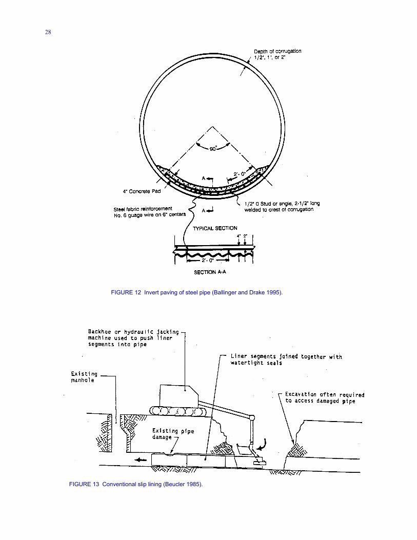
28
FIGURE 12 Invert paving of steel pipe (Ballinger and Drake 1995).
FIGURE 13 Conventional slip lining (Beucler 1985).
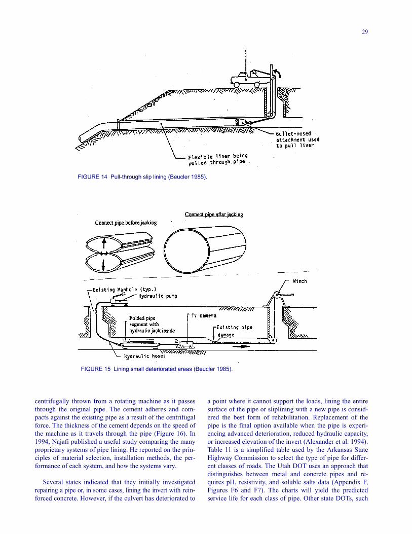
29
FIGURE 14 Pull-through slip lining (Beucler 1985).
FIGURE 15 Lining small deteriorated areas (Beucler 1985).
centrifugally thrown from a rotating machine as it passesthrough the original pipe. The cement adheres and com-pacts against the existing pipe as a result of the centrifugalforce. The thickness of the cement depends on the speed ofthe machine as it travels through the pipe (Figure 16). In1994, Najafi published a useful study comparing the manyproprietary systems of pipe lining. He reported on the prin-ciples of material selection, installation methods, the per-formance of each system, and how the systems vary.
Several states indicated that they initially investigatedrepairing a pipe or, in some cases, lining the invert with rein-forced concrete. However, if the culvert has deteriorated to
a point where it cannot support the loads, lining the entiresurface of the pipe or sliplining with a new pipe is consid-ered the best form of rehabilitation. Replacement of thepipe is the final option available when the pipe is experi-encing advanced deterioration, reduced hydraulic capacity,or increased elevation of the invert (Alexander et al. 1994).Table 11 is a simplified table used by the Arkansas StateHighway Commission to select the type of pipe for differ-ent classes of roads. The Utah DOT uses an approach thatdistinguishes between metal and concrete pipes and re-quires pH, resistivity, and soluble salts data (Appendix F,Figures F6 and F7). The charts will yield the predictedservice life for each class of pipe. Other state DOTs, such
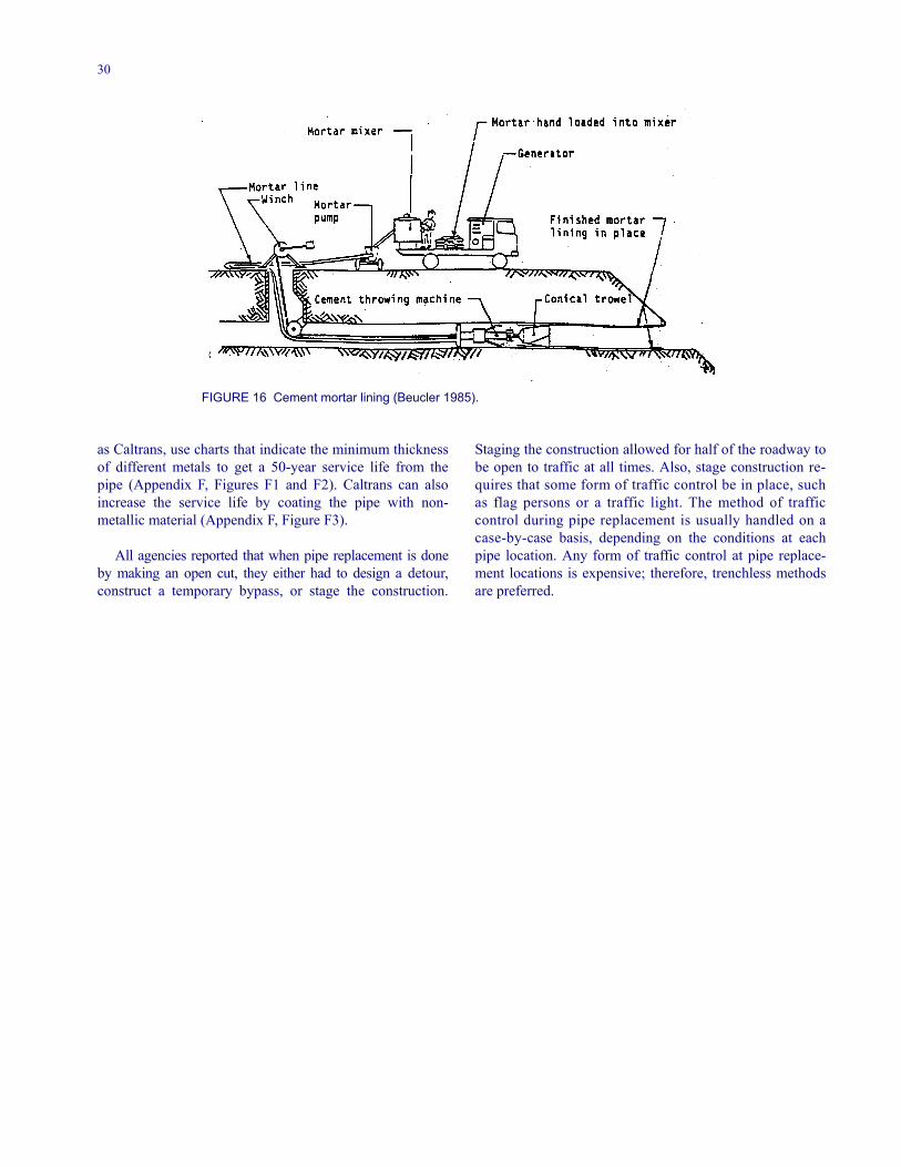
30
FIGURE 16 Cement mortar lining (Beucler 1985).
as Caltrans, use charts that indicate the minimum thicknessof different metals to get a 50-year service life from thepipe (Appendix F, Figures F1 and F2). Caltrans can alsoincrease the service life by coating the pipe with non-metallic material (Appendix F, Figure F3).
All agencies reported that when pipe replacement is doneby making an open cut, they either had to design a detour,construct a temporary bypass, or stage the construction.
Staging the construction allowed for half of the roadway tobe open to traffic at all times. Also, stage construction re-quires that some form of traffic control be in place, suchas flag persons or a traffic light. The method of trafficcontrol during pipe replacement is usually handled on acase-by-case basis, depending on the conditions at eachpipe location. Any form of traffic control at pipe replace-ment locations is expensive; therefore, trenchless methodsare preferred.
31
CHAPTER FOUR
PIPE MANAGEMENT ADMINISTRATION
MANAGEMENT SYSTEMS
Eleven agencies (19% of respondents) indicated that theyhad a management system that uses the pipe assessmentdata (Table 4). MDOT reported having a pipe managementsystem that is part of a larger system, TINIS, the Trans-portation Integrated Network Information System (Inven-tory of Managed Assets . . . 1999). The highway recordssystem has been in use since the early 1970s and containsthe inventory of managed assets that is accessed by using anode-link framework. A manual is provided to all person-nel using TINIS that describes the methods by which dataare collected and maintained. The collected data are storedin a centralized database, Inventory of Managed Assets,which supports TINIS. MDOT feels it is using its re-sources effectively by knowing the quantity, location, andcondition of its features. In addition, TINIS is made avail-able to those personnel responsible for maintaining thefeatures and planning the maintenance work effort. TINISprovides quick, desktop access to the data, and allows thestaff to plan their work, report their accomplishments, andmake their resource needs known to management. Appen-dix C contains two drainage items from the Inventory ofManaged Assets manual. The complete section for crossculverts and struts, excluding photographs, is shown inAppendix C. These sections illustrate the detail required todevelop a pipe management system that is a subset of alarger transportation system.
Caltrans, Utah DOT, and other transportation agenciesuse resistivity and pH charts to achieve the service life ex-pected or to determine the service life for a particular envi-ronmental situation (Appendix F, Figures F1–F7). Caltransalso has a computer program that can be used to estimatethe service life for various corrosive conditions. Generally,when service life is an issue, the deteriorated pipe is beingreplaced or lined by a new pipe.
The review of literature revealed that little work hasbeen done on developing a pipe or culvert managementsystem. In 1989, McNichol of the University of Kansasdeveloped a computer-based culvert management system.In 1991, Kurt and McNichol evaluated the system for theculvert systems of a local Kansas agency. The proposedcomputer system compared well with the existing replace-ment strategies. This system used four priority-rankingformulas that control user and agency cost. Those formulasconsidered the following factors: hydraulic capacity, loadcapacity, width deficiency, and maintenance costs. A
complete management system would involve an evalua-tion of the life-cycle costs, deterioration models for eachculvert type, and the effects of different maintenancestrategies. Also, in NCHRP Synthesis 254, the Arizona andMississippi DOTs were reported as having “a particularlywell-defined way of addressing and presenting the menu ofchoices that are associated with the desired service life”(Gabriel and Moran 1998). Included in the parameters thathave been evaluated by the states are the performances ofdifferent pipe materials; that is, steel, aluminum, concrete,and polyethylene, under various environmental conditionsand environments of service. Different states adopt theirown strategy to meet their needs from experiences with thevarious products.
To provide guidance to local governments and others,the FHWA, through the LTAP, developed a CMS (Thomp-son 2000). However, none of the responding agencies, in-cluding the local agencies, indicated that they are usingthis product in their work. A manual was published con-taining background information and the details of the sys-tem. A field manual was also created to aid the pipe in-spector during the evaluation of a pipe. A training coursewas developed to familiarize all personnel involved withthe pipe program and specifically the CMS. The finalproduct of the CMS is a computer software program de-signed to expedite the implementation process. The com-puter program contains five modules with flow diagramsand data forms. The five modules are: inventory of the cul-verts, condition and ratings, work needs (repair or reha-bilitation), work funding and prioritization, and scheduling(time of the year and whether in-house or contract). A flowdiagram with accompanying data forms to enable users tosuccessfully complete each module is also provided.NYSDOT takes the individual culvert rating data andsummarizes them into an annual culvert inspection report.Table 8 is a sample annual report generated from the ratingreports (Figure 8). NYSDOT stores its culvert data in acentralized database, but does not incorporate the data intoa larger management system, such as MDOT’s TINIS.Potter and Schindler suggested that life-cycle cost analysis(LCCA) be used to determine the relative economic ratingof design alternatives of U.S. Army drainage structures(Potter 1988; Potter and Schindler 1988). The use ofLCCA can improve the pipe and material selection processand can be done for each site. Once the service life of adrainage material is selected, the procedures for LCCA areestablished and published in U.S. Army technical manuals.The LCCA considers all costs, direct and indirect, that are
32
likely to occur over a selected period of the desired servicelife. Indirect costs, such as the cost of a detour to the userof the transportation system and other costs associated withthe disruption of services, need to be included. The alter-natives can then be selected from the generated life-cycleorder ranking (Potter 1988).
The American Concrete Pipe Association’s Least Cost(Life Cycle) Analysis microcomputer program comparesdifferent pipe materials based on design components andproject requirements (Kurdziel 1988). The program considersthe material service life, project design life, economic factors,and other factors specific to the project; for example, traf-fic costs. The National Corrugated Steel Pipe Associationhas also developed least-cost analysis software similar tothat of the American Concrete Pipe Association.
RECORD KEEPING
A key element for the generation of deterioration curvesfor individual pipes is derived from records collected overthe years that the inspections were performed. The datashould be transferred to a centralized database once the in-spection forms return to the office. After keying the data inor downloading the files, the hard copy reports should bekept for future reference. If there should be some discrep-ancies in the data, the hard copies can be secured and vali-dation of the data conducted.
Inspection Reports
Twenty-seven respondents (60% of those answering thisquestion) indicated that they kept the data generated fromtheir inspection programs (Table 4), with 18 agencies hav-ing an inspection program, but not keeping their data.
Several one-page inspection reports are being used bytransportation agencies, including PennDOT, Caltrans,NCDOT, Mn/DOT, and the Harford County Department ofPublic Works. An ideal inspection report would have guide-lines or rating scales as references on the one-page report. At aminimum, the guidelines or rating scales should be attached tothe report. PennDOT has a one-page report with the refer-ences at the bottom (Figure 2). A thorough understanding ofthe rating scale or guidelines is essential to collect accurateand consistent data. PennDOT provides training in the useof their report and the understanding of the guidelines andrating scales. Photographs are also an excellent aid forevaluators to use as a reference during field inspections.
Maintenance Reports
Eighteen of the 59 respondents (31%) to the questionnaireindicated that they had a preventative maintenance programand that they kept their data (Table 4). A preventative
maintenance program is a preferred process because in-spections can be planned on a regular schedule. However,most agencies responding to the survey, as well as the re-sults from the literature search, indicated that such pro-grams are not in place. As a result, most transportationagencies do not schedule pipe maintenance work, but waituntil a problem occurs or is detected through occasional,random inspections. If a preventative maintenance programis established, regularly scheduled inspections can be gen-erated from the existing database. Also, the program willallow the manager to change the frequency of inspectionsbased on the data accumulated over time. If the pipe is de-teriorating at a much faster rate due to a number of factors,the frequency of the inspections can be increased to avoidany failures; that is, from a 4-year cycle to a 2-year cycle.Conversely, the frequency of inspection can be decreased ifconditions are milder than anticipated.
SPECIFICATIONS
Thirty-one respondents (54%) indicated that they usedmaterial specifications from the construction unit duringthe rehabilitation of pipes (Table 4). Most state agenciesindicated that they use their own standard specificationsfor road and bridge construction, specifications ofAASHTO, or specifications of the American Society forTesting and Materials (ASTM; A849 and A979/A979M).Local agencies indicated that in most cases they use theirstate DOT’s specifications. With some pipe contracts, spe-cial provisions for pipe liner installations and other spe-cialized treatments are used in addition to the state’s stan-dard construction specifications. Wyoming’s SpecialProvision for Pipe Liner Installation (Appendix D) is anexample of such a special provision. This Special Provi-sion covers the description of the work, materials, con-struction, method of measurement, and basis of payment.NYSDOT is working to standardize their specifications toeliminate redundancies and inconsistencies between spe-cial specifications for different activities. A draft specifi-cation and design guidelines for rehabilitation of culvertand storm drains for future NYSDOT contracts are pro-vided in Appendix E. The NCDOT and Louisiana DOThave similar specifications for drains and pipes madefrom various materials, but these are not covered in thissynthesis.
Although specifications and special provisions are beingused, enhancement of specifications for lining and otherrehabilitation methods require further refinement. The lin-ing specifications need to be definitive as to the amount ofbend of the insert that will be tolerated before the insert isout of specification. In addition, the pressure required onthe grout to ensure that it is properly placed between thetwo pipes and that voids in the existing pipe and behind theexisting pipe are satisfactorily filled must be determined.
33
Specifications for rehabilitation work are different fromthe specifications used to place a pipe in an open cut. Opencut specifications deal with compaction of the backfill andbedding material, but rehabilitation specifications do not.In rehabilitation work a clean existing pipe is essential. Allloose material must be removed by either water or sandblasting to ensure proper bonding of the existing culvertwith the new lining material. In some pipes there are utilityservices. Specifications need to cover the responsibility ofthese utilities and the re-establishing of services to theiroriginal condition. Another concern for some of the proc-esses used in pipe rehabilitation work involves the curingof the materials. The specifications need to state the tem-perature levels expected in curing and cooling the products.
Also, the contractor will need to provide points on the in-coming and outgoing supply lines to monitor these tem-peratures for compliance. These examples of specificationsneeded for rehabilitation work are not all-inclusive, but areexamples of the unique specifications needed for rehabili-tation work. In addition, these specifications will differ de-pending on the type of rehabilitation work being done; thatis, lining with a pipe, cement mortar lining, or lining asmall deteriorated section of the existing pipe. ASTM hastwo specifications that could be used as guides in the de-velopment of lining specifications, specifications for lininga pipe in the manufacturer’s plant, ASTM A849-00(ASTM 2001) and ASTM A979/979M-97, the specifica-tion for lining a pipe in the field (ASTM 2001).
34
CHAPTER FIVE
CONCLUSIONS
From the results of the literature search and the survey oftransportation agencies, it was discovered that there is noconsistent and comprehensive methodology among trans-portation agencies to inventory, inspect, and evaluate pipesand culverts in the field. Several agencies have portions ofa comprehensive system, but not one has a complete sys-tem in place.
Transportation agencies that have implemented a man-agement system, for example, pavement, bridge, or sign,usually gradually expand and enhance their system, be-cause they realize its benefits and how it allows them tobetter manage their assets. This progression would inevita-bly occur with a pipe management system once a trans-portation agency implemented a pipe system.
The Maine Department of Transportation (MDOT) has themost comprehensive system of all agencies responding to thesurvey. Once pipe data are collected, the data are entered in acentralized database that will eventually load into a largermanagement system, the Transportation Integrated NetworkInformation System (TINIS). The data in TINIS can be usedfor planning, projecting, forecasting, funding, and schedulinginspection times. If similar methodologies were developed byother agencies, the resulting database could provide muchuseful information for developing improved service-lifepredictions and generating pipe deterioration curves. Ofthose responding to the survey, MDOT’s DOT’s systemwas the best example of how a pipe assessment guidelinecan be incorporated into a master management system.
NYSDOT, Caltrans, PennDOT, NCDOT, Mn/DOT,ConnDOT, Maryland State Highway Administration(MDSHA), and the Harford County (Maryland) Depart-ment of Public Works have pipe management systems es-tablished that could be helpful to an agency just gettingstarted in this area. Summary sheets of the condition ratingforms for the individual pipes are generated by most ofthese agencies. In addition, each transportation agency hasdetailed training guidelines for their different ratings andmost of the agencies include photographs for better under-standing. A pipe evaluator in these systems is trained onthe system prior to the fieldwork, so that accurate and con-sistent data are collected by different evaluators even indifferent regions of the transportation agency.
Most of the agencies responding to the survey do nothave a regular pipe inspection schedule because they do
not have a systematic, preventative maintenance program.Some transportation agencies inspect pipes every 4 years,whereas others inspect pipes when time and funding allow.The FHWA has suggested that inspections be scheduledevery 2 years for larger pipes and culverts. The MDSHAhas a pipe management program where each pipe is in-spected every 4 years unless the pipe conditions deterio-rate, in which case the pipe is placed on a 2-year inspectioncycle.
In addition to the repair or replacement of a deterioratedpipe found during infrequent inspections, repairs or reha-bilitation are also scheduled when a defect, such as road-way settlement, occurs unexpectedly. Such repair or reha-bilitation jobs are generally expensive and create othermaintenance scheduling problems.
The type of defect dictates the type of repair required. Ifa pipe has deteriorated to a point where more than repairwork is required (rehabilitation), most agencies indicated apreference to lining the existing pipe rather than replacingit.
Only one responding agency, the Alameda County Pub-lic Works Agency, indicated that they used a video camerato inspect pipes. The remaining respondents did not specifythe use of a video camera, but indicated that they per-formed most of their evaluations from the ends of the pipe(i.e., visually). The condition of the pipe’s interior and theappurtenances is determined by an inspector who looksthrough the pipe with a light.
There have been a number of studies on the load capac-ity of pipes and the compaction of the soil around thepipes. In addition, a number of studies on the abrasion, cor-rosion, and durability of various types of pipes, metal pipesin particular, have been conducted over the last 75 years.States have documented relationships between the durabil-ity and service life of various types of pipes from thesestudies and use charts and graphs with these relationshipsto determine what type of pipe to use to replace an existingpipe.
With these study findings in mind, the following aresome opportunities for future research.
• Transportation agencies would benefit from guide-lines for a preventative maintenance program to
35
inventory and inspect culverts on a regular schedule.Such a program might include the pipe inventory,guidelines for evaluation of the pipes, photographsrelated to the guidelines, frequency of inspection, andtraining for the inspectors. The guidelines might indi-cate a means of inspecting the interior of small-diameter pipes. Another issue is centralizing culvertdata at the appropriate management level, so thatanalyses can be performed to determine when toschedule pipe inspections, schedule corrective main-tenance action, and generate history and deteriorationcurves for various conditions.
• Specifications for pipe lining need to be developed.The Wyoming DOT’s Special Provision for PipeLiner Installation and NYSDOT specifications shownin Appendixes D and E, respectively, are examplesthat could be referred to in setting a strategy for de-veloping specifications, as well as ASTM’s A849-00Specification for post-applied linings in a manufac-turer’s plant and A979/A979M-97 Specification forfield installed linings.
• A follow-up study could be undertaken to develop acomprehensive pipe management system that alltransportation agencies could use. As this synthesisshows, there is currently little attention paid to pipemanagement systems; that is, being proactive bymanaging the pipe infrastructure. When pipes fail forwhatever reason agencies react and take correctiveaction. If a comprehensive pipe management system
was in use, the agency would be managing the system(proactive), rather than being at the mercy of the sys-tem (reactive). A proactive system would includeguidelines and photographs for inspection, frequencyof inspections, standard data forms, guidelines fordetermining the corrective action needed (repair, re-habilitation, or replacement), record-keeping proce-dures, analytical methods for determining pipe con-dition or deterioration rate, and the economic analysisof the action to be taken. To implement this systemand ensure that no one agency would be financiallyburdened, a number of agencies could pool theirfunds and share the cost of this development. Onestate could be designated to handle the administrativeand day-to-day operations of the project and coordi-nate the project activities with a consultant. An esti-mate of the cost of the project would need to be de-termined, so that each of the agencies could shareequally in the cost. At the conclusion of the projecteach agency would have the latest techniques and asystem ready for implementation as described in thefinal report.
• Transportation agencies could benefit from develop-ing methods to use during inspection to estimate theremaining service life of a pipe with various defectsor levels of deterioration. An inspector could use themethods to estimate the service life and provide themanager with the data to better schedule maintenanceto the pipe.
36
REFERENCES
Alexander, J.A., T.C. Sandford, and A. Seshadri, Reha-bilitation of Large Diameter Steel Culverts, Maine De-partment of Transportation, Technical Services Divi-sion, Augusta, Maine, December 1994.
American Association of State Highway and Transporta-tion Officials (AASHTO), AASHTO Highway DrainageGuidelines: Volume 14—Culvert Inspection, MaterialSelection and Rehabilitation, AASHTO, Washington,D.C., August 1999, 60 pp.
Arnoult, J.D., Culvert Inspection Manual: Supplement tothe Bridge Inspector’s Training Manual, ReportFHWA-IP-86-002, Federal Highway Administration,McLean, Va., July 1986, 215 pp.
Ault, J.P. and J.A. Ellor, Durability Analysis of AluminizedType 2 Corrugated Metal Pipe, Report FHWA-RD-97-140, Federal Highway Administration, McLean, Va.,January 2000, 106 pp.
Ballinger, C.A. and P.G. Drake, Culvert Repair PracticesManual, Vols. 1 and 2, Reports FHWA-RD-94-096 andFHWA-RD-95-089, Federal Highway Administration,McLean, Va., May 1995, (Vol. 1) 265 pp. and (Vol. 2)354 pp.
Bealey, M., “Precast Concrete Pipe Durability: State of theArt,” Transportation Research Record 1001, Transpor-tation Research Board, National Research Council,Washington, D.C., 1984, pp. 88–94.
Beucler, B., Pipe Rehabilitation on Skyline Drive—Shen-andoah National Park, Report FHWA EP-85-004, Fed-eral Highway Administration, Washington, D.C., 1985.
Cerlanek,W.D. and R.G. Powers, Drainage Culvert ServiceLife Performance and Estimation, Report 93-4a, FloridaDepartment of Transportation, Corrosion ResearchLaboratory, Tallahassee, Fla., April 1993.
Chambers, R.E., T.J. McGrath, and F.J. Heger, NCHRPReport 225: Plastic Pipe for Subsurface Drainage ofTransportation Facilities, Transportation ResearchBoard, National Research Council, Washington, D.C.,October 1980, 153 pp.
Coated Steel Products, Standards Vol. 01.06, AmericanSociety for Testing and Materials, West Conshohocken,Pa., 2001.
Department of the Army, Economic Studies for Military Con-struction Design—Applications, Manual TM 5-802-1, De-partment of the Army, Washington, D.C., December 31,1986.
Drainage Condition Survey Field Manual, Publ. 73, Penn-sylvania Department of Transportation, Harrisburg,April 1999.
Duncan, C.R., “Innovated Repair of a Large Failing StructuralSteel Plate Pipe Arch Culvert,” Transportation ResearchRecord 1001, Transportation Research Board, NationalResearch Council, Washington, D.C., 1984, pp. 98–101.
Gabriel, L.H. and E.T. Moran, NCHRP Synthesis 254:Service Life of Drainage Pipe, Transportation ResearchBoard, National Research Council, Washington, D.C.,1998, 39 pp.
Gift, A. and B. Smith, Culvert Study Report, Research In-vestigation 91-11, Missouri Department of Transporta-tion, Jefferson City, August 2000.
Goble, G., NCHRP Synthesis of Highway Practice 276:Geotechnical Related Development and Implementationof Load and Resistance Factor Design (LRFD) Meth-ods, Transportation Research Board, National ResearchCouncil, Washington, D.C., 1999, 69 pp.
Guidelines for Culvert Relining, Lane Enterprises, Inc.,Camp Hill, Pa., Revised May 1999.
Hixon, C.D., Performance of Polyethylene Pipe in Okla-homa, Oklahoma Department of Transportation, Okla-homa City, June 1992.
Ikerd, S.R., “Invert Replacement of Corrugated MetalStructural Plate Pipe,” Transportation Research Rec-ord 1001, Transportation Research Board, NationalResearch Council, Washington, D.C., 1984, pp. 102–103.
Inventory of Managed Assets—Data Collection Manual,Maine Department of Transportation, Maintenance andOperations, Augusta, August 1999, 59 pp.
Jackson, G.W. and M. Subramanian, A Literature Reviewfor a Study of an Accelerated Laboratory Test to Deter-mine Durability of Pipe Culvert Material, Ohio De-partment of Transportation (ODOT) Contract 5813,ODOT, Columbus, November 1990.
Jenkins, S.V. and J.L. Leatham, Pipe Culvert Durability,Report MR-88-02, Utah Department of Transportation,Salt Lake City, March 1988.
Kurdziel, J.M., “Culvert Durability Rating Systems,”Transportation Research Record 1191, TransportationResearch Board, National Research Council, Washing-ton, D.C., 1988, pp. 132–140.
Kurdziel, J.M., “Least Cost (Life Cycle) Analysis Micro-computer Program,” Transportation Research Record1191, Transportation Research Board, National Re-search Council, Washington, D.C., 1988, pp. 141–154.
Kurt, C.E. and G.W. McNichol, “Microcomputer-BasedCulvert Ranking System,” Transportation Research Re-cord 1315, Transportation Research Board, NationalResearch Council, Washington, D.C., 1991, pp. 21–27.
MacDougall, C.A., Culvert Inventory and Inspection Man-ual, New York State Department of Transportation, Al-bany, December 1991, 146 pp.
Mathioudakis, M. and A. Agarwal, Re-Evaluation of De-sign Procedures for Non-Bridge-Size Culverts, ClientReport 74, New York State Department of Transporta-tion, Albany, May 1996, 30 pp.
37
McGrath, T.J. and V.E. Sagan, NCHRP Report 438: Rec-ommended LRFD Specifications for Plastic Pipe andCulverts, Transportation Research Board, National Re-search Council, Washington, D.C., 2000, 69 pp.
McNichol, G.W., Development of a Microcomputer BasedCulvert Management System, Department of Civil En-gineering, University of Kansas, Lawrence, 1989.
Najafi, M., Trenchless Pipeline Rehabilitation, MissouriWestern State College, St. Joseph, Mo., 1994.
National Association of Sewer Service Companies(NASSCO), Manual of Practices, NASSCO, Maitland,Fla., August 1996.
NCHRP Synthesis of Highway Practice 50: Durability ofDrainage Pipe, Transportation Research Board, NationalResearch Council, Washington, D.C., 1978, 37 pp.
NCHRP Report 222: Bridges on Secondary Highways andLocal Roads—Rehabilitation and Replacement, Trans-portation Research Board, National Research Council,Washington, D.C., 1980, 132 pp.
NCHRP Report 243: Rehabilitation and Replacement ofBridges on Secondary Highways and Local Roads,Transportation Research Board, National ResearchCouncil, Washington, D.C., December 1981, 46 pp.
Okpala, D. and W. Anderson, Culvert Pipe RehabilitationUsing Slip-Liners, Wisconsin Department of Transpor-tation, Madison, February 1997, 9 pp.
Pipe Selection for Corrosion Resistance, ImplementationPackage UDOT-IMP-76-1, Utah Department of Trans-portation, Research and Development Unit, Salt LakeCity.
Potter, J.C., Life Cycle Cost for Drainage Structures,Technical Report GL-88-2, Department of the Army,
Waterways Experimental Station, U.S. Army Corps ofEngineers, Vicksburg, Miss., February 1988.
Potter, J.C., I. Lewandowski, and D.W..White, Durabilityof Special Coatings for Corrugated Steel Pipe, ReportFHWA-FLP-91-006, Federal Highway Administration,McLean, Va., June 1991.
Potter, J.C. and L. Schindler, “Life-Cycle Cost for Designof Army Drainage Structures,” Transportation ResearchRecord 1191, Transportation Research Board, NationalResearch Council, Washington, D.C., 1988, pp. 106–112.
Ring, G.W., “Culvert Durability: Where Are We?,” Trans-portation Research Record 1001, Transportation Re-search Board, National Research Council, Washington,D.C., 1984, pp. 1–9.
Sukley, R. and B. St. John, Evaluation of INSITUFORMPipe Rehabilitation, PA-94-002-84-103, PennsylvaniaDepartment of Transportation, Harrisburg, October1994.
Thompson, R.E., Culvert Management System (CMS) forLocal Governments, Federal Highway Administration,McLean, Va., 2000.
“Symposium on Durability of Culverts and Storm Drains,”Transportation Research Record 1001, TransportationResearch Board, National Research Council, Washing-ton, D.C., 1984, 114 pp.
Tymkowicz, S., Pipe Rehabilitation with Polyethylene PipeLiners—Construction Report, Iowa Department ofTransportation, Ames, March 1995, 59 pp.
Welch, B.H., Pipe Corrosion and Protective Coatings,Utah State Department of Highways, Salt Lake City,November 12, 1974, 72 pp.
38
GLOSSARY
Most of the definitions used in this synthesis were from Ballinger and Drake (1995). A set of definitions was needed sothat all users of this synthesis could understand the specifics used in this work, even though these definitions may be dif-ferent from the ones used in their agency. Also, other sources and different state DOTs may not use the same definitionsbecause they may prefer to specify a characteristic, such as a different length or opening area for a bridge, culvert, or pipe.The following list defines most of the terms pertinent to this synthesis and is not exhaustive.
Bridge—Structure more than 20 feet in span parallel withthe roadway.
Cement mortar lining—Cement mortar grout centrifugallyapplied to the interior of existing culverts. Grout is ap-plied after cleaning the pipe to protect the pipe andmaintain capacity.
Culvert—Structure usually designed hydraulically to takeadvantage of submergence to increase hydraulic capac-ity; structure used to convey surface runoff through anembankment; structure, as distinguished from bridges,that is usually covered with an embankment and iscomposed of structural material around the entire pe-rimeter, although some are supported on spread footingswith the streambed serving as the bottom of the culvert;and a structure that is 20 feet or less in centerline lengthbetween extreme ends of openings for multiple barrels(see Bridge). (Note: In this report when pipes are men-tioned culverts are included.)
Durability—Ability to perform its function and withstandits working environment over time or service life.
Inversion lining—Process of inverting pliable tubing intoexisting pipe with hydrostatic or air pressure to relineexisting pipe. The liner is forced against the existingpipe and bonded with thermosetting resins to providestructural strength and improve smoothness.
Invert—Flowline of the culvert (inside bottom) of thetransverse cross section of a pipe.
Link pipe lining—Method of pulling a short, folded pipe-line segment to the damaged point in an existing pipeand unfolding or spreading the segment into place byjacking.
Patching—Corrective action taken on a specific area of apipe surface to keep the pipe in a uniformly good andsafe condition. Spalling, abrasion, impact, or someother type of loading could cause the defect.
Pipe—Tube or conduit used to convey a fluid. Sometimescalled a culvert, storm drain, or storm sewer. A pipecan be made from a number of materials, includingsteel, concrete, iron, aluminum, polyethylene, high-density polyethylene, or polyvinylchloride.
Preventative maintenance—Maintenance performed to ar-rest light deterioration that has occurred and to preventprogressive deterioration. Preventative maintenance iscyclic in nature and can be scheduled. Typical activitiesinclude joint sealing, concrete patching, invert paving,and mortar repair.
Rehabilitation—Corrective action that takes advantage ofthe remaining unusable structure in a culvert to build areconditioned culvert. The action taken will upgradethe pipe to almost its original condition. Rehabilitationis most appropriate for culverts that have deterioratedbeyond the point of effective preventative maintenance,but that have not deteriorated to the point where allstructural integrity has been lost.
Repair—Corrective action to keep a culvert in a uniformlygood and safe condition by correcting specific defects.
Routine maintenance—Maintenance performed on a pipeto keep it in a uniformly good and safe condition by re-pairing specific defects as they occur. Routine mainte-nance is often reactive to a situation rather than being ascheduled activity. Typical activities include debris orsediment removal to restore the pipe cross-sectionalarea.
Shotcrete lining—Application of pneumatically appliedcement plaster or concrete to an in-place structure to in-crease structural strength and improve the surfacesmoothness.
Sliplining—The process of placing a smaller diameter pipein a larger diameter existing pipe to improve the culvertstructure and repair leaks. The annular space betweenthe pipes is usually filled with grout applied under pres-sure.
Storm drain—Structure used to convey runoff from astorm event. Sometimes called a pipe or culvert.
Storm sewer—Structure used to convey storm runoffwhere storm sewers and storm drains are connected.Sometimes called a pipe or culvert.
Structural plate pipe or arch—Plates of corrugated struc-tural steel used to fabricate large culvert structures suchas arches or boxes.
39
APPENDIX A
Survey Questionnaire
NATIONAL COOPERATIVE HIGHWAY RESEARCH PROGRAMProject 20-5, Topic 31-03
ASSESSMENT AND REHABILITATION OF EXISTING CULVERTS
QUESTIONNAIRE
Respondent’s Agency
Respondent
Title
Address
Phone Number Fax Number
E-mail Address
PLEASE RETURN QUESTIONNAIRE AND SUPPORTING DOCUMENTS BY May 10, 2000
TO: David Wyant
Wilbur Smith Associates4686 Garth RoadCrozet, Virginia 22932(804) 823-1360 (804) 823-5102 (Fax)
For questions it would be best to contact David Wyant by e-mail: [email protected]
Note: Help from you or someone in your agency familiar with culvert repair and rehabilitation is greatly appreciated.Thanks in advance for your efforts.
Objective of Project—NCHRP plans to publish a synthesis report on transportation agency state-of-the-practice for as-sessing pipe condition and selecting the appropriate repair or rehabilitation methods for these pipes. Through this ques-tionnaire and a literature search, it is anticipated that methods of assessment, repair, and rehabilitation for plastic, concrete,and metal pipes will be determined. The synthesis will also report the type of inspection and maintenance records thattransportation agencies keep on pipe condition. Hopefully, how the methods of assessment, repair, or rehabilitation forpipes are incorporated into a management system can also be reported in this study. Cast-in-place and bridge structures willnot be considered, while system appurtenances, such as drainage inlets, manholes, junction boxes, headwalls, endwalls,and wingwalls will be.
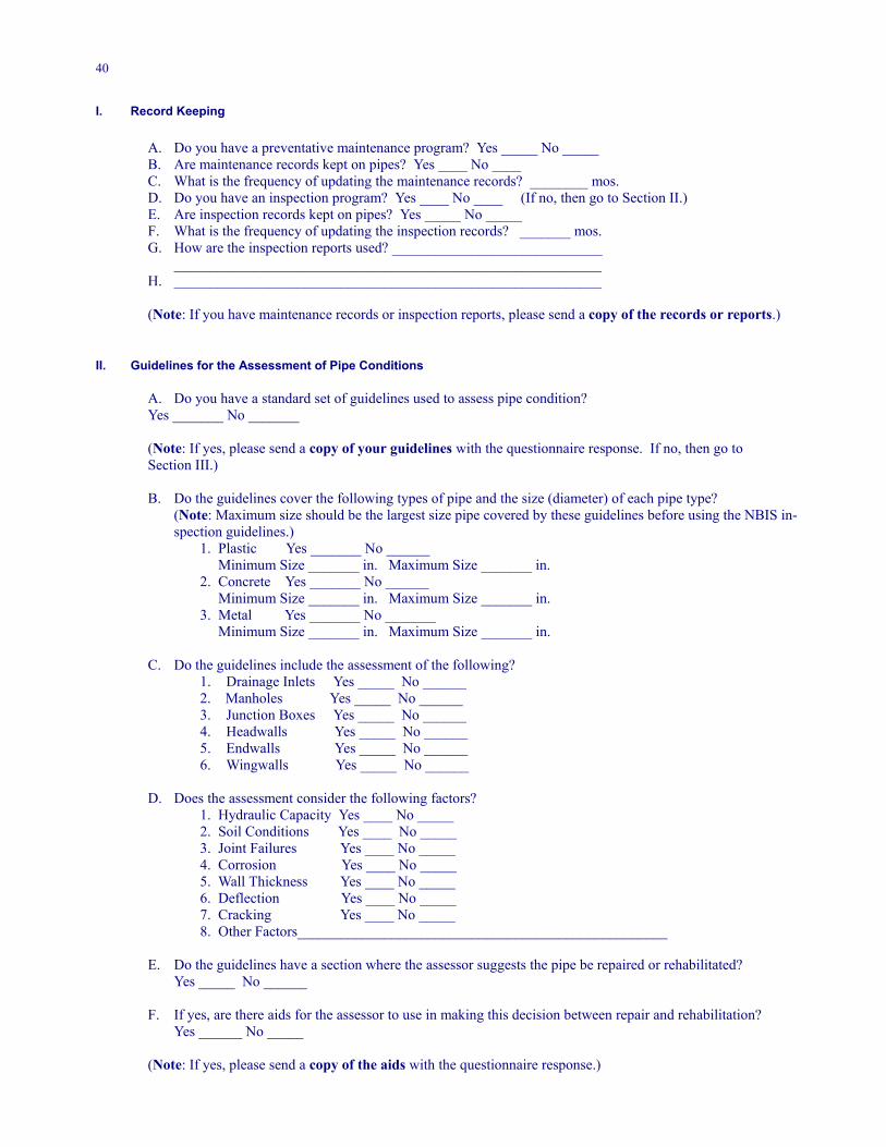
40
I. Record Keeping
A. Do you have a preventative maintenance program? Yes _____ No _____B. Are maintenance records kept on pipes? Yes ____ No ____C. What is the frequency of updating the maintenance records? ________ mos.D. Do you have an inspection program? Yes ____ No ____ (If no, then go to Section II.)E. Are inspection records kept on pipes? Yes _____ No _____F. What is the frequency of updating the inspection records? _______ mos.G. How are the inspection reports used? _____________________________
___________________________________________________________H. ___________________________________________________________
(Note: If you have maintenance records or inspection reports, please send a copy of the records or reports.)
II. Guidelines for the Assessment of Pipe Conditions
A. Do you have a standard set of guidelines used to assess pipe condition?Yes _______ No _______
(Note: If yes, please send a copy of your guidelines with the questionnaire response. If no, then go toSection III.)
B. Do the guidelines cover the following types of pipe and the size (diameter) of each pipe type?(Note: Maximum size should be the largest size pipe covered by these guidelines before using the NBIS in-spection guidelines.)
1. Plastic Yes _______ No ______ Minimum Size _______ in. Maximum Size _______ in.2. Concrete Yes _______ No ______
Minimum Size _______ in. Maximum Size _______ in.3. Metal Yes _______ No _______
Minimum Size _______ in. Maximum Size _______ in.
C. Do the guidelines include the assessment of the following?1. Drainage Inlets Yes _____ No ______2. Manholes Yes _____ No ______3. Junction Boxes Yes _____ No ______4. Headwalls Yes _____ No ______5. Endwalls Yes _____ No ______6. Wingwalls Yes _____ No ______
D. Does the assessment consider the following factors? 1. Hydraulic Capacity Yes ____ No _____ 2. Soil Conditions Yes ____ No _____ 3. Joint Failures Yes ____ No _____ 4. Corrosion Yes ____ No _____ 5. Wall Thickness Yes ____ No _____ 6. Deflection Yes ____ No _____ 7. Cracking Yes ____ No _____ 8. Other Factors___________________________________________________
E. Do the guidelines have a section where the assessor suggests the pipe be repaired or rehabilitated?Yes _____ No ______
F. If yes, are there aids for the assessor to use in making this decision between repair and rehabilitation?Yes ______ No _____
(Note: If yes, please send a copy of the aids with the questionnaire response.)
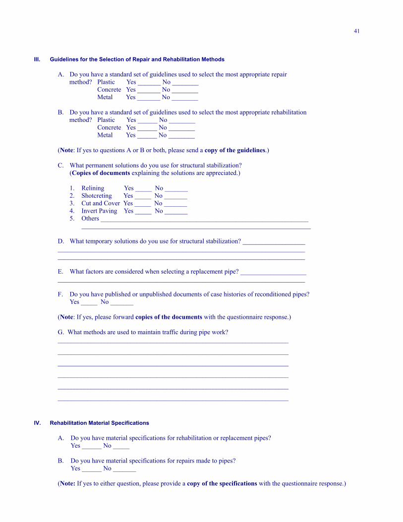
41
III. Guidelines for the Selection of Repair and Rehabilitation Methods
A. Do you have a standard set of guidelines used to select the most appropriate repair method? Plastic Yes _______ No ________
Concrete Yes _______ No ________ Metal Yes _______ No ________
B. Do you have a standard set of guidelines used to select the most appropriate rehabilitation method? Plastic Yes ______ No ________ Concrete Yes ______ No ________
Metal Yes ______ No ________
(Note: If yes to questions A or B or both, please send a copy of the guidelines.)
C. What permanent solutions do you use for structural stabilization?(Copies of documents explaining the solutions are appreciated.)
1. Relining Yes _____ No _______2. Shotcreting Yes _____ No _______3. Cut and Cover Yes _____ No _______4. Invert Paving Yes _____ No _______5. Others _______________________________________________________________
D. What temporary solutions do you use for structural stabilization? _________________________________________________________________________________________________________________________________________________________________________
E. What factors are considered when selecting a replacement pipe? _______________________________________________________________________________________________
F. Do you have published or unpublished documents of case histories of reconditioned pipes?Yes _____ No _______
(Note: If yes, please forward copies of the documents with the questionnaire response.)
G. What methods are used to maintain traffic during pipe work?______________________________________________________________________
______________________________________________________________________
______________________________________________________________________
______________________________________________________________________
______________________________________________________________________
______________________________________________________________________
IV. Rehabilitation Material Specifications
A. Do you have material specifications for rehabilitation or replacement pipes?Yes ______ No _____
B. Do you have material specifications for repairs made to pipes?Yes ______ No _______
(Note: If yes to either question, please provide a copy of the specifications with the questionnaire response.)
42
V. Methods of Predicting Service Life of Culverts and Pipes
A. Do you have a method or methods for predicting the service life of a pipe or culvert?Plastic Yes ______ No ______Concrete Yes ______ No ______Metal Yes ______ No ______Other Yes ______ No ______
(Note: If yes, please provide a copy of the method with the questionnaire response.)
VI. Management Systems
A. Do you have a management system that uses the data from the pipe assessment?Yes ______ No ______
B. Do the guidelines for assessment of pipe conditions result in a priority list, which is subject to monetaryconstraints? Yes _____ No _____
C. What type system are you using?1. Risk analysis ________________2. Life-cycle-cost optimization _______________3. Prioritization ________________4. Planning ________________5. Other ________________________________________
(Note: If you have a management system, please forward a copy of the system with the questionnaireresponse.)
Please provide copies of all of your supporting documents and reports for the questions along with the questionnaire re-sponse to the following address by May 10th.
David WyantWilbur Smith Associates4686 Garth RoadCrozet, Virginia 22932
Thank you for your time and contribution to this study!
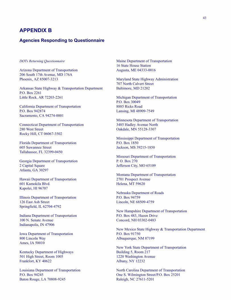
43
APPENDIX B
Agencies Responding to Questionnaire
DOTs Returning Questionnaire
Arizona Department of Transportation206 South 17th Avenue, MD 176APhoenix, AZ 85007-3213
Arkansas State Highway & Transportation DepartmentP.O. Box 2261Little Rock, AR 72203-2261
California Department of TransportationP.O. Box 942874Sacramento, CA 94274-0001
Connecticut Department of Transportation280 West StreetRocky Hill, CT 06067-3502
Florida Department of Transportation605 Suwannee StreetTallahassee, FL 32399-0450
Georgia Department of Transportation2 Capital SquareAtlanta, GA 30297
Hawaii Department of Transportation601 Kamokila Blvd.Kapolei, HI 96707
Illinois Department of Transportation126 East Ash StreetSpringfield, IL 62704-4792
Indiana Department of Transportation100 N. Senate AvenueIndianapolis, IN 47906
Iowa Department of Transportation800 Lincoln WayAmes, IA 50010
Kentucky Department of Highways501 High Street, Room 1005Frankfort, KY 40622
Louisiana Department of TransportationP.O. Box 94245Baton Rouge, LA 70808-9245
Maine Department of Transportation16 State House StationAugusta, ME 04333-0016
Maryland State Highway Administration707 North Calvert StreetBaltimore, MD 21202
Michigan Department of TransportationP.O. Box 300498885 Ricks RoadLansing, MI 48909-7549
Minnesota Department of Transportation3485 Hadley Avenue NorthOakdale, MN 55128-3307
Mississippi Department of TransportationP.O. Box 1850Jackson, MS 39215-1850
Missouri Department of TransportationP. O. Box 270Jefferson City, MO 65109
Montana Department of Transportation2701 Prospect AvenueHelena, MT 59620
Nebraska Department of RoadsP.O. Box 94759Lincoln, NE 68509-4759
New Hampshire Department of TransportationP.O. Box 483, Hazen DriveConcord, NH 03302-0483
New Mexico State Highway & Transportation DepartmentP.O. Box 91750Albuquerque, NM 87199
New York State Department of TransportationBuilding 5, Room 2171220 Washington AvenueAlbany, NY 12232
North Carolina Department of TransportationOne S. Wilmington Street/P.O. Box 25201Raleigh, NC 27611-5201
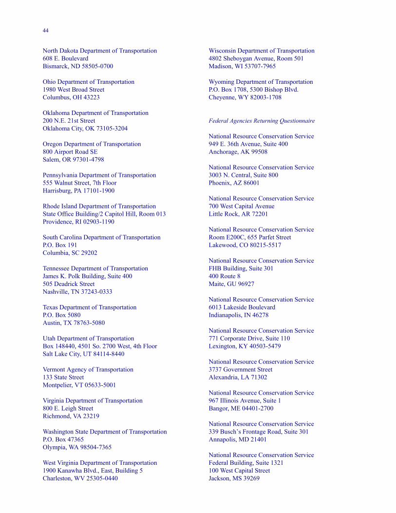
44
North Dakota Department of Transportation608 E. BoulevardBismarck, ND 58505-0700
Ohio Department of Transportation1980 West Broad StreetColumbus, OH 43223
Oklahoma Department of Transportation200 N.E. 21st StreetOklahoma City, OK 73105-3204
Oregon Department of Transportation800 Airport Road SESalem, OR 97301-4798
Pennsylvania Department of Transportation555 Walnut Street, 7th FloorHarrisburg, PA 17101-1900
Rhode Island Department of TransportationState Office Building/2 Capitol Hill, Room 013Providence, RI 02903-1190
South Carolina Department of TransportationP.O. Box 191Columbia, SC 29202
Tennessee Department of TransportationJames K. Polk Building, Suite 400505 Deadrick StreetNashville, TN 37243-0333
Texas Department of TransportationP.O. Box 5080Austin, TX 78763-5080
Utah Department of TransportationBox 148440, 4501 So. 2700 West, 4th FloorSalt Lake City, UT 84114-8440
Vermont Agency of Transportation133 State StreetMontpelier, VT 05633-5001
Virginia Department of Transportation800 E. Leigh StreetRichmond, VA 23219
Washington State Department of TransportationP.O. Box 47365Olympia, WA 98504-7365
West Virginia Department of Transportation1900 Kanawha Blvd., East, Building 5Charleston, WV 25305-0440
Wisconsin Department of Transportation4802 Sheboygan Avenue, Room 501Madison, WI 53707-7965
Wyoming Department of TransportationP.O. Box 1708, 5300 Bishop Blvd.Cheyenne, WY 82003-1708
Federal Agencies Returning Questionnaire
National Resource Conservation Service949 E. 36th Avenue, Suite 400Anchorage, AK 99508
National Resource Conservation Service3003 N. Central, Suite 800Phoenix, AZ 86001
National Resource Conservation Service700 West Capital AvenueLittle Rock, AR 72201
National Resource Conservation ServiceRoom E200C, 655 Parfet StreetLakewood, CO 80215-5517
National Resource Conservation ServiceFHB Building, Suite 301400 Route 8Maite, GU 96927
National Resource Conservation Service6013 Lakeside BoulevardIndianapolis, IN 46278
National Resource Conservation Service771 Corporate Drive, Suite 110Lexington, KY 40503-5479
National Resource Conservation Service3737 Government StreetAlexandria, LA 71302
National Resource Conservation Service967 Illinois Avenue, Suite 1Bangor, ME 04401-2700
National Resource Conservation Service339 Busch’s Frontage Road, Suite 301Annapolis, MD 21401
National Resource Conservation ServiceFederal Building, Suite 1321100 West Capital StreetJackson, MS 39269
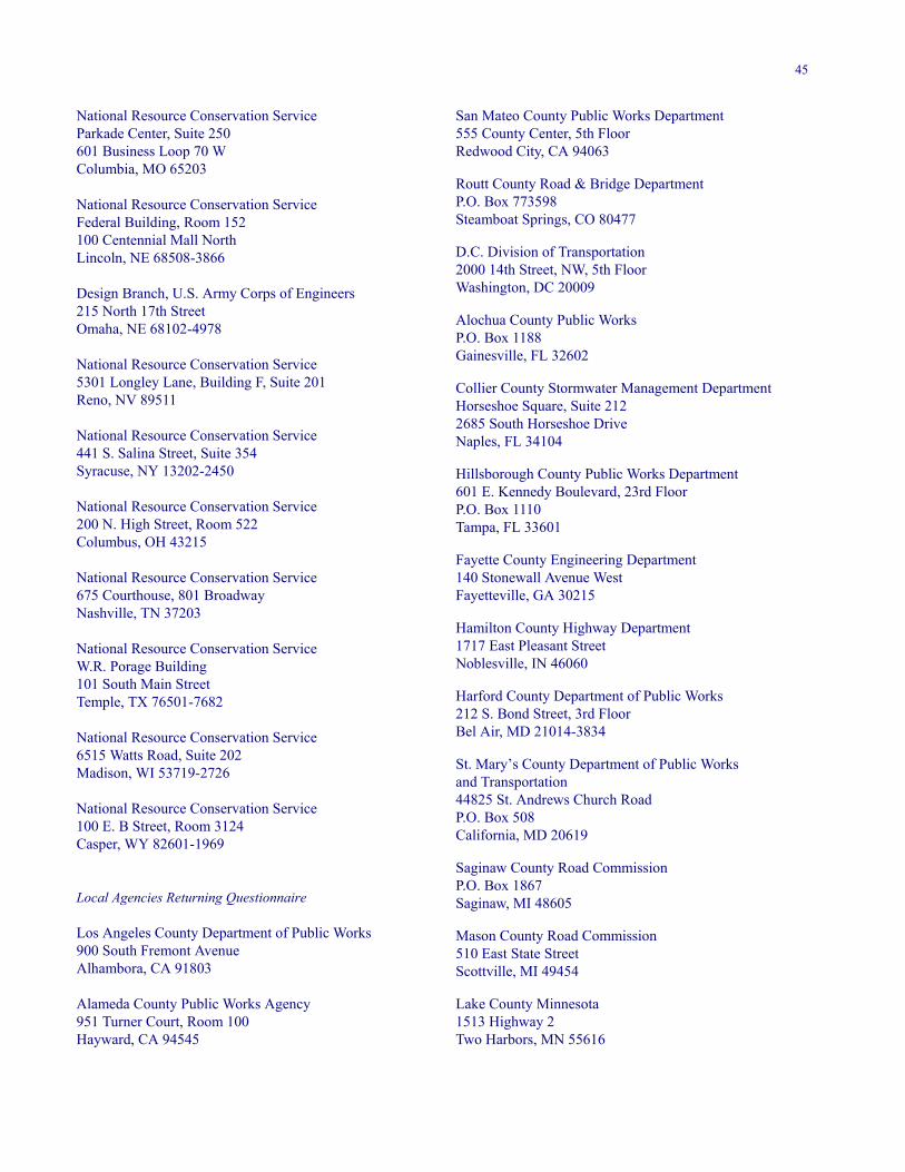
45
National Resource Conservation ServiceParkade Center, Suite 250601 Business Loop 70 WColumbia, MO 65203
National Resource Conservation ServiceFederal Building, Room 152100 Centennial Mall NorthLincoln, NE 68508-3866
Design Branch, U.S. Army Corps of Engineers215 North 17th StreetOmaha, NE 68102-4978
National Resource Conservation Service5301 Longley Lane, Building F, Suite 201Reno, NV 89511
National Resource Conservation Service441 S. Salina Street, Suite 354Syracuse, NY 13202-2450
National Resource Conservation Service200 N. High Street, Room 522Columbus, OH 43215
National Resource Conservation Service675 Courthouse, 801 BroadwayNashville, TN 37203
National Resource Conservation ServiceW.R. Porage Building101 South Main StreetTemple, TX 76501-7682
National Resource Conservation Service6515 Watts Road, Suite 202Madison, WI 53719-2726
National Resource Conservation Service100 E. B Street, Room 3124Casper, WY 82601-1969
Local Agencies Returning Questionnaire
Los Angeles County Department of Public Works900 South Fremont AvenueAlhambora, CA 91803
Alameda County Public Works Agency951 Turner Court, Room 100Hayward, CA 94545
San Mateo County Public Works Department555 County Center, 5th FloorRedwood City, CA 94063
Routt County Road & Bridge DepartmentP.O. Box 773598Steamboat Springs, CO 80477
D.C. Division of Transportation2000 14th Street, NW, 5th FloorWashington, DC 20009
Alochua County Public WorksP.O. Box 1188Gainesville, FL 32602
Collier County Stormwater Management DepartmentHorseshoe Square, Suite 2122685 South Horseshoe DriveNaples, FL 34104
Hillsborough County Public Works Department601 E. Kennedy Boulevard, 23rd FloorP.O. Box 1110Tampa, FL 33601
Fayette County Engineering Department140 Stonewall Avenue WestFayetteville, GA 30215
Hamilton County Highway Department1717 East Pleasant StreetNoblesville, IN 46060
Harford County Department of Public Works212 S. Bond Street, 3rd FloorBel Air, MD 21014-3834
St. Mary’s County Department of Public Worksand Transportation44825 St. Andrews Church RoadP.O. Box 508California, MD 20619
Saginaw County Road CommissionP.O. Box 1867Saginaw, MI 48605
Mason County Road Commission510 East State StreetScottville, MI 49454
Lake County Minnesota1513 Highway 2Two Harbors, MN 55616
46
APPENDIX C
Examples of Pipe Guidelines and Specifications
47
48
49
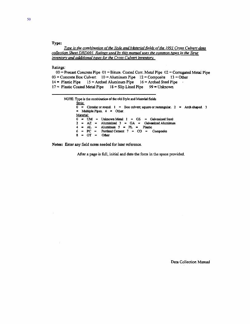
50
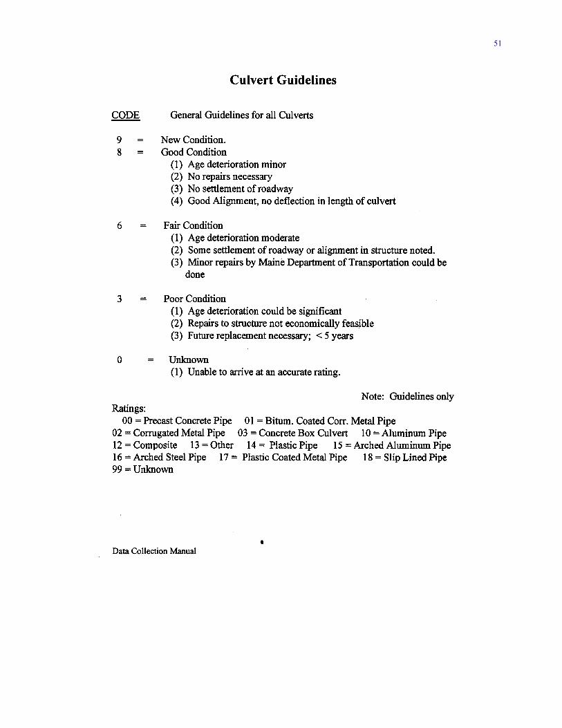
51
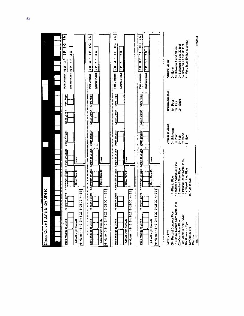
52
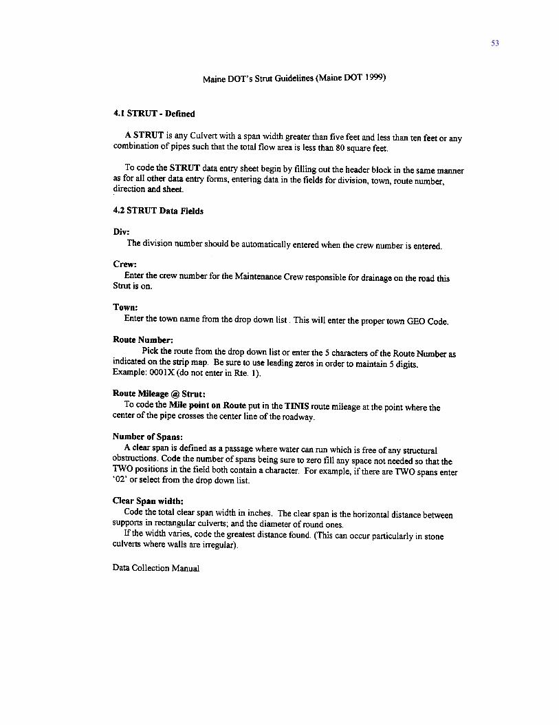
53
54
55
56
57
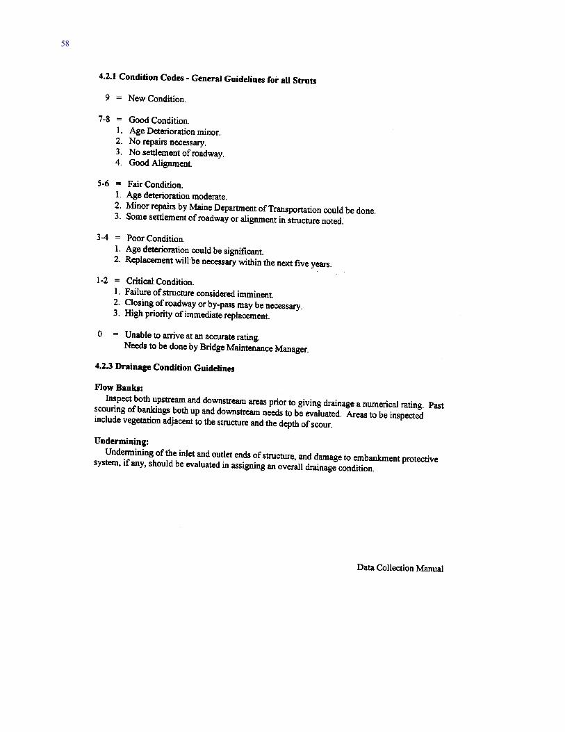
58
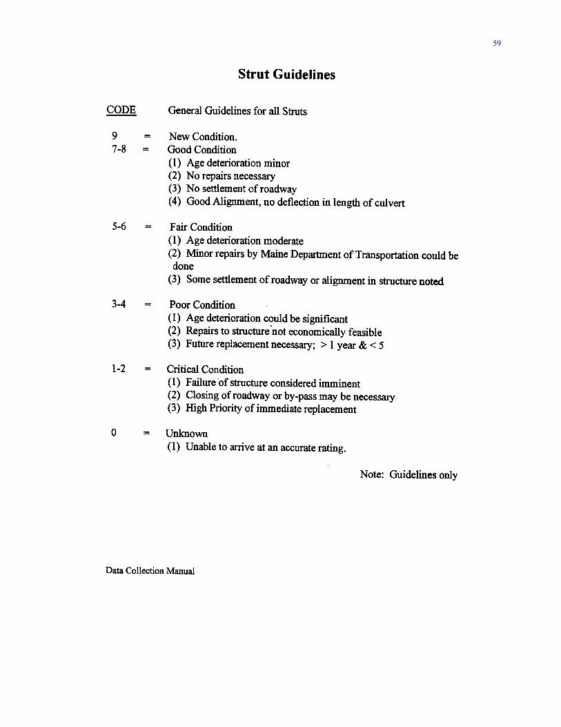
59
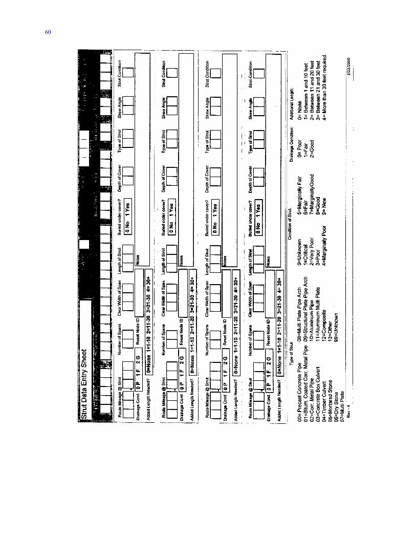
60
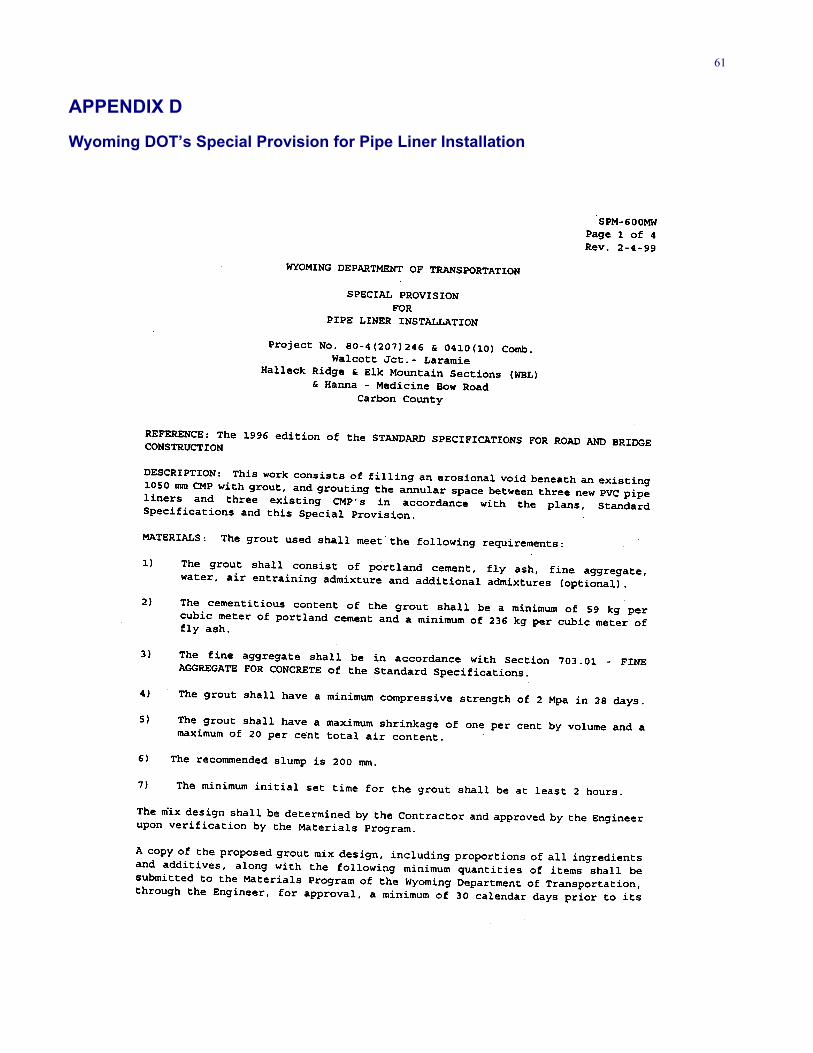
61
APPENDIX D
Wyoming DOT’s Special Provision for Pipe Liner Installation
62
63
64
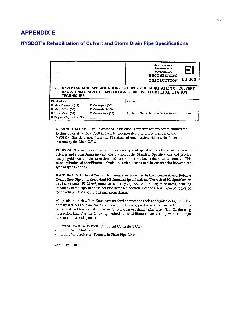
65
APPENDIX E
NYSDOT’s Rehabilitation of Culvert and Storm Drain Pipe Specifications
66
67
68
APPENDIX F
Pipe Durability
Durability can be broadly defined as the ability of a pipe toperform its function and withstand degradation. From amaterial standpoint, degradation can occur in the form ofcracking, tearing, spalling, abrading, or corroding. How-ever, deterioration can also include joint separation or fail-ure, structural failure through buckling or deflection, aswell as any other factors that reduce a pipe’s ability tofunction. Durability is very important to a pipe’s longevity,but is only one element of an assessment guideline. Severalother factors that play a role in the deterioration of a pipeand that should be included in an assessment guideline arehydraulic capacity, joint failures, deflection, and cracking.
For those who would like to learn more about the dura-bility of pipes there are a number of studies that have beenconducted on this subject over the last 75 years and coverthe subject in greater detail. In 1984, Bealey reported that33 states and numerous researchers had published a total of131 reports on the durability of pipe materials. Of these re-ports, 63% were concerned with corrugated metal pipe,28% covered multiple pipe materials, 5% dealt with con-crete, and 4% were concerned with various other issues.From Bealey’s report it was apparent that in 1984 durabil-ity was an issue to more than 60% of the state transporta-tion agencies.
Other publications on durability include NCHRP Syn-thesis of Highway Practice 50: Durability of DrainagePipe (1978), Gift and Smith (2000), Gabriel and Moran(1998), Jackson and Subramanian (1990), Kurdziel (1988),“Symposium on the Durability of Culverts and StormDrains” (1984), Ault and Ellor (2000), and Cerlanek andPowers (1993). The “Symposium on the Durability of Cul-verts and Storm Drains” (Transportation Research Record
1001), authored by Bealey (1984), is a state of the practiceof concrete pipe durability. In addition, FHWA Report RD-97-140, Durability Analysis of Aluminized Type 2 Corru-gated Metal Pipe, authored by Ault and Ellor (January2000) and NCHRP Synthesis of Highway Practice 254:Service Life of Drainage Pipe, authored by Gabriel andMoran (1998), provide current information on pipe dura-bility (for complete citations of all reports cited in this ap-pendix, see References). FHWA Report RD-97-140 docu-ments culvert durability from the findings of a literaturereview and from field investigations of aluminized type 2corrugated metal culverts. The results of this study aid inthe selection of pipe material and durability predictionmethods. NCHRP Synthesis 254 provides a state-of-thepractice overview of the service life of pipes. The UtahDOT and California DOT (Caltrans), as well as othertransportation agencies, have developed charts to selectpipes from pH and/or resistivity values. Figures F1–F3 arethe charts Caltrans uses to select metal pipes. The NationalCorrugated Steel Pipe Association has developed industry-wide durability guidelines, which address the service lifeof galvanized corrugated steel pipe and supplementalcoatings (Figures F4 and F5). This methodology is basedon the Caltrans method, which included add-on service lifefor nonmetallic coatings. Figures F6 and F7 are examplesof what the Utah DOT uses for metal and concrete pipeselection in corrosive situations (Welch 1974). Jenkins andLeatham (March 1988) evaluated the Utah DOT’s pipeselection procedures from the standpoint of durability,stating that, “The resulting correlation between life expec-tancy at different ages was good.” Other states also con-tinue to use the basic charts developed in the 1970s and1980s and update them to reflect the conversion to metricand any refinements discovered during usage.
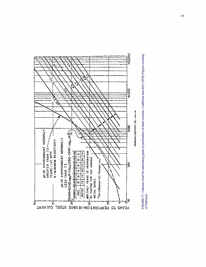
69
FIG
UR
E F1
Cal
trans
cha
rt fo
r est
imat
ing
year
s to
per
fora
tion
of s
teel
cul
verts
—C
alifo
rnia
test
643
(197
8) (F
igur
e co
urte
syof
Cal
trans
).
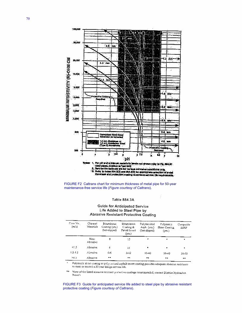
70
FIGURE F2 Caltrans chart for minimum thickness of metal pipe for 50-yearmaintenance-free service life (Figure courtesy of Caltrans).
FIGURE F3 Guide for anticipated service life added to steel pipe by abrasive resistant protective coating (Figure courtesy of Caltrans).
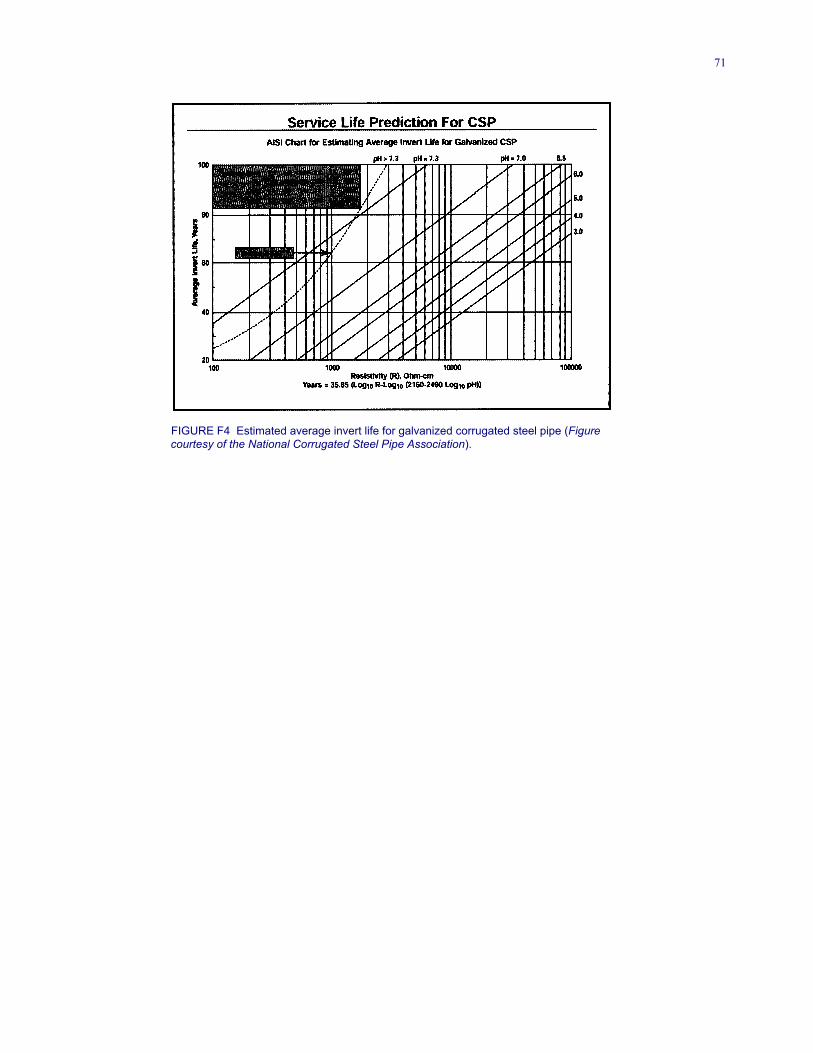
71
FIGURE F4 Estimated average invert life for galvanized corrugated steel pipe (Figure courtesy of the National Corrugated Steel Pipe Association).
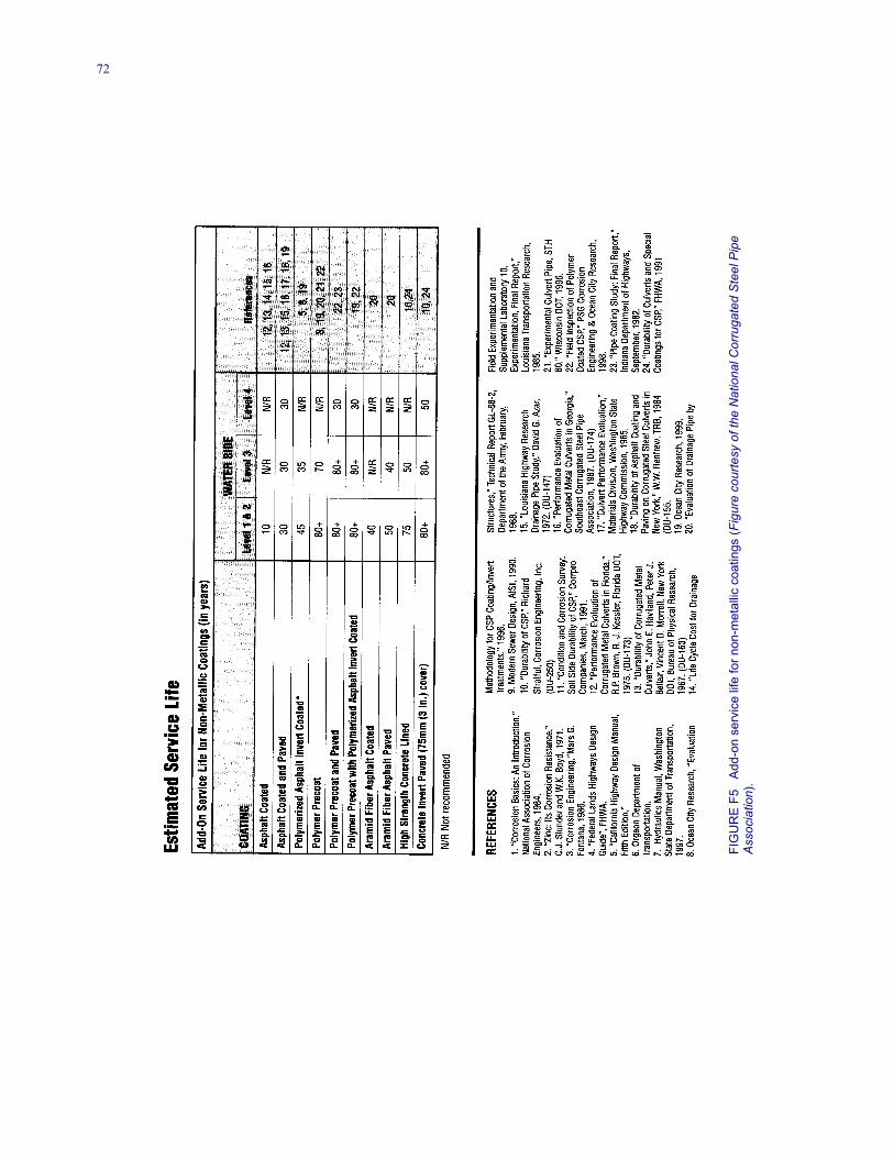
72
FIG
UR
E F5
Add
-on
serv
ice
life
for n
on-m
etal
lic c
oatin
gs (F
igur
e co
urte
sy o
f the
Nat
iona
l Cor
ruga
ted
Stee
l Pip
eAs
soci
atio
n).
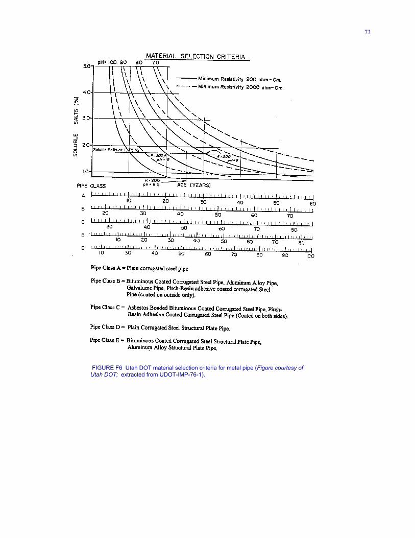
73
FIGURE F6 Utah DOT material selection criteria for metal pipe (Figure courtesy of Utah DOT; extracted from UDOT-IMP-76-1).

74
FIGURE F7 Utah DOT material selection criteria for concrete pipe (Figure courtesy of Utah DOT; extracted from UDOT-IMP-76-1).
THE TRANSPORTATION RESEARCH BOARD is a unit of the National ResearchCouncil, a private, nonprofit institution that provides independent advice on scientific andtechnical issues under a congressional charter. The Research Council is the principal operatingarm of the National Academy of Sciences and the National Academy of Engineering.
The mission of the Transportation Research Board is to promote innovation and progressin transportation by stimulating and conducting research, facilitating the dissemination ofinformation, and encouraging the implementation of research findings. The Board’s variedactivities annually draw on approximately 4,000 engineers, scientists, and other transportationresearchers and practitioners from the public and private sectors and academia, all of whomcontribute their expertise in the public interest. The program is supported by statetransportation departments, federal agencies including the component administrations of theU.S. Department of Transportation, and other organizations and individuals interested in thedevelopment of transportation.
The National Academy of Sciences is a nonprofit, self-perpetuating society of distinguishedscholars engaged in scientific and engineering research, dedicated to the furtherance ofscience and technology and to their use for the general welfare. Upon the authority of thecharter granted to it by the Congress in 1863, the Academy has a mandate that requires it toadvise the federal government on scientific and technical matters. Dr. Bruce Alberts ispresident of the National Academy of Sciences.
The National Academy of Engineering was established in 1964, under the charter of theNational Academy of Sciences, as a parallel organization of outstanding engineers. It isautonomous in its administration and in the selection of its members, sharing with theNational Academy of Sciences the responsibility for advising the federal government. TheNational Academy of Engineering also sponsors engineering programs aimed at meetingnational needs, encouraging education and research, and recognizes the superior achievementsof engineers. Dr. William A.Wulf is president of the National Academy of Engineering.
The Institute of Medicine was established in 1970 by the National Academy of Sciencesto secure the services of eminent members of appropriate professions in the examination ofpolicy matters pertaining to the health of the public. The Institute acts under theresponsibility given to the National Academy of Sciences, by its congressional charter to bean adviser to the federal government and, upon its own initiative, to identify issues ofmedical care, research, and education. Dr. Harvey V. Fineberg is president of the Institute ofMedicine.
The National Research Council was organized by the National Academy of Sciences in1916 to associate the broad community of science and technology with the Academy’spurposes of furthering knowledge and advising the federal government. Functioning inaccordance with general policies determined by the Academy, the Council has become theprincipal operating agency of both the National Academy of Sciences and the NationalAcademy of Engineering in providing services to the government, the public, and thescientific and engineering communities. The Council is administered jointly by bothAcademies and the Institute of Medicine. Dr. Bruce Alberts and Dr. William A. Wulf arechairman and vice chairman, respectively, of the National Research Council.