national electrical safety code (nesc) · rule 097a requires separate grounding conductors except...
TRANSCRIPT

1
Update on Safety CodesNational Electrical Safety Code (NESC)
California GOs-95, -165 Contact:
Trevor N. Bowmer, Ph.D.Senior Analyst - EricssonTelcordia - Network Infrastructure Solutions (NIS)[email protected]. 732.699.3341
Presented at:
Annual ConferenceMarch 25-27, 2013 Littleton CO
Ericsson

2
Code Overview Codes - NESC…GO 95…NEC….OSHA…. Best Practices – Personal Safety & Facilities Reliability Engineering Design for Efficient & Reliable Operation
Issues (active) Bonding & Grounding Congestion – on Poles and in Buried locations Scope Boundaries of NESC/NECWork Rules - Tests and Inspections Clearances Pole Loading and Strength
Plans and Paths Forward - 2014/2015 NESC Preprint Blue Book Revision (Issue 6)
Ericsson

3
Adventures in Code Land
IEEE – NESCNFPA -- NECGO-95.. GO-165 OSHA Internal M&Ps GRs and UL Listings
Joint Use Agreements (JUA) UL GRs/SRs ATIS etc……
Industry Safety Codes and StandardsRegulatory Rules……...…. Legal Mandates Internal Practices…………Engineering Design
Ericsson

4
National Electrical Safety CodePurpose : The practical safeguarding of persons, utility facilities, and affected property during the installation, operation, and maintenance of electric supply and communication facilities.
Contains the basic provisions that are considered necessary for the safeguarding of the public, utility workers and utility facilities under the specified conditions.
Ericsson
2012 (current) -- ---- 2017 Code
Scope: The NESC covers supply and communication facilities and associated work practices employed by a public or private electric supply, communications, railway, or similar entity in the exercise of its function as a utility.
Facilities = lines, equipment, and specified infrastructure(e.g., poles, sub-stations, vaults…)
The NESC covers similar systems under the exclusive control of the utility and being worked by qualified persons, such as those associated with an industrial complex or utility interactive system.

5
National Electrical Safety Code NESC is not intended as a design specification or as an instruction
manual – http://standards.ieee.org/about/nesc The implicit assumption exists that regular operational cooperation as well as
formal joint-use agreements (JUAs) exist between all power and telecom utilities sharing a pole, underground vault, location or area.
Ericsson
6
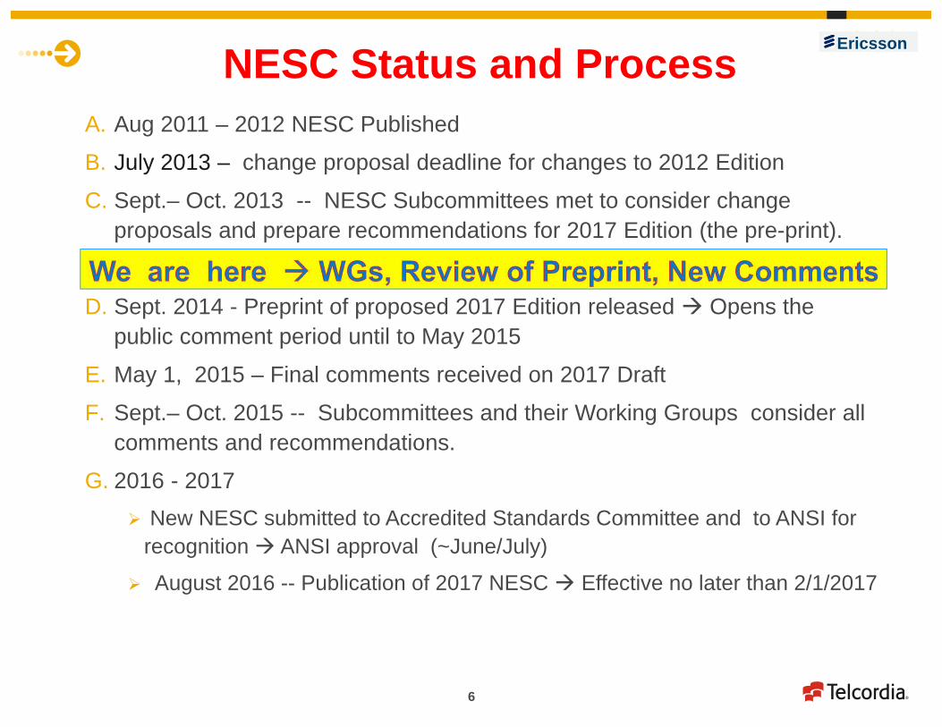
NESC Status and ProcessA. Aug 2011 – 2012 NESC Published
B. July 2013 – change proposal deadline for changes to 2012 Edition
C. Sept.– Oct. 2013 -- NESC Subcommittees met to consider change proposals and prepare recommendations for 2017 Edition (the pre-print).
D. Sept. 2014 - Preprint of proposed 2017 Edition released Opens the public comment period until to May 2015
E. May 1, 2015 – Final comments received on 2017 Draft
F. Sept.– Oct. 2015 -- Subcommittees and their Working Groups consider all comments and recommendations.
G. 2016 - 2017 New NESC submitted to Accredited Standards Committee and to ANSI for
recognition ANSI approval (~June/July)
August 2016 -- Publication of 2017 NESC Effective no later than 2/1/2017
Ericsson

7
Main Drivers for NESC ChangesPRIMARY = REACTIVE Problems, issues and conflicts revealed during active use of NESC
Problems during Engineering/Design/Planning activities Joint-Use Agreement Conflicts Regulatory Inspections - OSHA and AHJ Compliance Regulatory Harmonization and Feedback
FCC, Public utilities – Boards and Commissions Field incidents, accidents, and legal cases
SECONDARY = PROACTIVE (5 year code cycle limits reaction time)
Mismatch of new technologies to practices based on traditional code
Intersystem Grounding & Bonding Wireless Antennas – Growth into Femtocells and DAS systems Smart Grid Devices – joint power and communications functions Alternate and hybrid sources of energy – wind, solar, etc….
Ericsson

8
Underlying Concerns & Issues -1• Bonding and Grounding (Rule 96C, 097, 097G, 099, 384)
• Different stakeholders have different purposes and objectives• Delineate purpose of grounding and bonding • Protect people and equipment from effects of lightning, power fault, stray current and induced
voltages
• Congestion on Poles and in Buried locations (Sections 2 and 3)• Multiple joint users and competing users for available space on pole and under the ground
• Scope Boundaries of NESC/NEC - Codes Inter-Relationship - NESC…NEC…GO95• Competition for AHJ control of areas – safety, permits, control and economics ($$)• Alternative and distributed generation systems:
• Risk Management - Work Rules - Worker & Public Safety (Part 4 - Work Rules)• Work Skill/Experience/Training ….M&Ps….Engineering Controls • Contact Avoidance…Minimum Approach Distance - IEEE 516/OSHA • PPE - Voltage detectors, clothing, equipment • Emergency restoration Vs. standard work operations (Applicable Construction Grade )
• Regulatory and Legal – inspections, documentation & records• Conditions versus Defects• Extraordinary threats versus “expected” stresses
Ericsson

9
Underlying Concerns & Issues - 2• Clearance and Separation
• Avoiding conflicts - field problems and failures• Clarification of code – consistency of interpretation and calculation• Failure at times of emergency power outage and service loss at most
inconvenient time• Pole Loading and Strength
• Accurate prediction of pole performance under “all” expected conditions • Normal circumstances - loadings of cables and equipment – for many
decades of use• Regular variations – winter to summer, rain storms to snow/ice to wind• Extreme events – 50 year ….100 year event ….?
• Fair and Consistent application of safety factors -• Load & Resistance Factor Design (LRFD) Vs. Allowable strength Design
(ASD)• Regulatory – “will not fail” …..high reliability objectives• Safety FactorsCompeting Views from
Engineers (Design/Plan) --- Statisticians – Meteorologists – Regulators --- AHJs
Ericsson

10
Code Overview and Background Codes - NESC…GO 95…NEC….OSHA…. Best Practices – Personal Safety & Facilities Reliability Engineering Design for Efficient & Reliable Operation
Issues (active) Bonding & Grounding Congestion – on Poles and in Buried locations Scope Boundaries of NESC/NECWork Rules - Tests and Inspections Clearances Pole Loading and Strength
Plans and Paths Forward - 2014/2015 NESC Preprint Blue Book Revision (Issue 6)
Ericsson

11
GROUNDING AND BONDING
Ericsson
Key NESC Rules
Rule 097 - Separation of Grounding Conductors
Rule 099 - Additional Requirements for Grounding and Bonding of Communications Apparatus

12
Why Bond And Ground?Appropriate Bonding and Grounding Helps to Ensure
the Safety of the Outside Plant Network, Employees and PublicSAFETY
Reduce the hazard of electric shock to employees and the public from unintentional contact with power faults and power crosses
Limits the extent and minimize the damage caused by lightning (but cannot prevent damage entirely)
To reduce corrosion and subsequent deterioration of hardware/anchors that could put a pole line’s integrity in jeopardy.
QUALITY OF SERVICE To reduce noise in telecommunications circuitsINTEGRITY OF THE NETWORK -- To mitigate
Effects of power surge voltages and currents in telecom facilities -- it is important to establish and maintain continuity of the cable shield
Electrolysis which can cause corrosion of shield, strand, and anchor Damage to electronic equipment and telephone plant caused by
power & lightning surges
Ericsson

13
Grounding and Bonding Issues “Effective Grounding” – New definitions in and use throughout code to help
delineate the purpose of grounding and bonding
Grounding system needs sufficiently low impedance or resistance to: Enable protection circuits for the power system to operate rapidly and
efficientlyDrain unwanted, foreign voltages or currents to earth (ground) thereby
minimizing hazards to workers and equipment. Intersystem grounding and bonding – Where and when to bond or not to
bond (Rules 096, 097G, 344, 354, 384C)…
Grounding Conductor - Alternative conductor design 30% vs.. 40% conductivity
Long Spans – Change to Rule 096C to allow not require opening of jacket sheath to only ground the shield (Rule 096C)
Ericsson

14
Bond Copper cable shield to strand at least every ¼ mile Strands of separate copper cables on same pole together every ¼ mile. Attachments to strand dead ends. Communications attachments to communications grounds where they exist. Strands that intersect from different copper cable leads (crossover poles)
Ground Strand dead ends Supporting messenger (strand) every 1320 feet (1/4 mile) with Ground Bed
Baseline Guidance - Aerial Plant Ericsson

15
Intersystem Bonding: Pole MGN
Ground rod
Pole Power Lines
Communications Lines
Strand
VerticalPole Ground
Neutral
• Rule 97G - single ground on structure to which all parties bond • Rule 215C - requires effective grounding of equipment/closures
General Rule Bond telecom grounds to the MGN
Exceptions Single Point Grounded (Delta) Supply Systems Pole Ground is Dedicated to Lightning and Surge
Arrestors
Ericsson
16
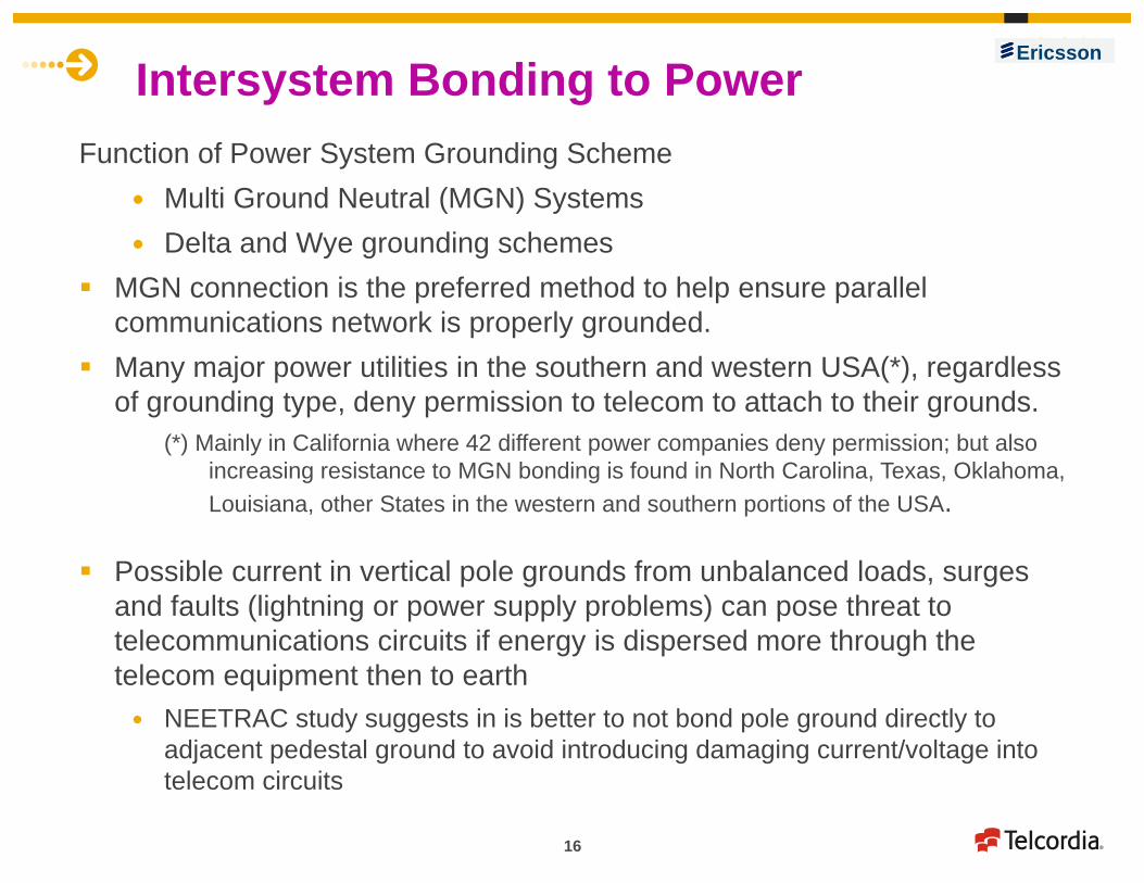
Intersystem Bonding to PowerFunction of Power System Grounding Scheme
Multi Ground Neutral (MGN) Systems Delta and Wye grounding schemes
MGN connection is the preferred method to help ensure parallel communications network is properly grounded.
Many major power utilities in the southern and western USA(*), regardless of grounding type, deny permission to telecom to attach to their grounds.
(*) Mainly in California where 42 different power companies deny permission; but also increasing resistance to MGN bonding is found in North Carolina, Texas, Oklahoma, Louisiana, other States in the western and southern portions of the USA.
Possible current in vertical pole grounds from unbalanced loads, surges and faults (lightning or power supply problems) can pose threat to telecommunications circuits if energy is dispersed more through the telecom equipment then to earth NEETRAC study suggests in is better to not bond pole ground directly to
adjacent pedestal ground to avoid introducing damaging current/voltage into telecom circuits
Ericsson

17
Buried—Aerial : To Bond or Not to Bond?Pole
Aerial Power Lines
Buried Communications Lines
Supply Ground
Rod
VerticalPole Ground
Communications Pedestal
VerticalPole Ground
Bond to MGN Pole Ground
Power and Communications Lines Diverge Pole Ground is Dedicated to certain
Lightning and Surge Arrestors
Telecom Ground Rod
Buried Plant Rules 342 & 384Bond communications and supply facilities
that are within 6 feet of one another.
Ericsson

18
Rule 097 has seven (7) individual interlocking sections with connections to other rules (e.g., 096, 224, 344, 354 and 384) applicable to intersystem bonds Rule 097A requires separate grounding conductors except as permitted
by 097B providing 097C (4 grounds/mile)is met. Rule 097B – permits a bond to the power ground where a MGN system
is being used and providing Rule 097C (i.e., 4 grounds/mile) is met. The combination of Rule 097B with 097C is the basis for the practice of
bonding communications to the vertical pole supply ground in MGN systems with a 6AWG conductor and approved connector. It is highly desirable to maintain and encourage this practice with an intersystem bond between power and communications systems as the first choice if practical.
Rule 097C - 4 grounds/mile criteria for an effective ground Rule 097G requires a single grounding conductor on structures except
as required by Rule 097A One objective of Rule 097G is to distinguish between intersystem bonding
necessary in cases of MGN power systems as opposed to ungrounded or single grounded systems.
EricssonRule 097 - Separation of Grounding Conductors

19
Rule 097G Proposals
Change accepted as follows –G. Bonding of communication systems to electric supply systems
Where both electric supply systems and communication systems are to be grounded on a the samejoint use structure, either a single grounding conductor shall be used for both systems or the electric supply and communication grounding conductors shall be bonded together, except where separation is required by Rule 097A. Where the electric supply utility is maintaining isolation between primary and secondary neutrals, the communication system ground shall be connected only to the primary grounding conductor if it complies with the requirements of Rule 097C.
Telcordia supported this actions as the best interim measure with the following affirmative comment in ballot :
“These accepted changes to Rule 097G help clarify the rule. However, the last sentence of revised Rule 097G requires work to better clarify when, and when not, a bond is appropriate between communications grounds and supply grounds in single-point grounded systems and cases where isolation is being used in power system. Further work on a revision to the last sentence of Rule 097G should be considered.”
Ericsson
Current 097G

20
Alternative Rule 097G - Planned as a Submission as a Comment to Preprint
G. Bonding of communication systems to electric supply systemsWhere both electric supply systems and communication systems are grounded on a joint use structure, either a single grounding conductor shall be used for both systems or the electric supply and communication grounding conductors shall be bonded together, except where separation is required by Rule 097A. Where the electric supply utility is maintaining isolation between primary and secondary neutrals, the communications system ground shall be connected as follows:
1. Ungrounded or single-grounded systemsThe communication system ground shall be connected only to the secondary neutral’s grounding conductor
2. Multi-grounded systemsThe communication system ground shall be connected only to the primary grounding conductor.
Ericsson
21
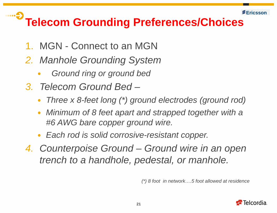
Telecom Grounding Preferences/Choices
1. MGN - Connect to an MGN 2. Manhole Grounding System
Ground ring or ground bed
3. Telecom Ground Bed – Three x 8-feet long (*) ground electrodes (ground rod) Minimum of 8 feet apart and strapped together with a
#6 AWG bare copper ground wire. Each rod is solid corrosive-resistant copper.
4. Counterpoise Ground – Ground wire in an open trench to a handhole, pedestal, or manhole.
(*) 8 foot in network….5 foot allowed at residence
Ericsson

22
Bond cable shield to power neutral ground at At least every other terminal not to exceed 1000 feet At terminal nearest each transformer At all aboveground terminals, apparatus cases, and cable closures which are
within 6 feet of any above ground power apparatusSince in many or most cases, no access to power bonding & grounding
source is available. Place a ground bed Place ground at the beginning and end of the laterals and major branch splices Bond cable shields
Within 500 ft of first transition point (e.g., pedestal, crossbox) Within 500 ft of the CO side of any new buried cable pulling off from an existing
route (branch location). At least every other terminal so as not to exceed 1000 ft to a ground bed. Within 500 ft of the end of the cable route, no additional ground rods are
required.
Buried Plant Ericsson

23
Change to Rule 096C accepted to add an exception
Do not need to open jacket sheath to only ground the shield (Rule 096C)Long spans with limited access and reduced exposure Long underground runs with no splices or connection points (closures) Water crossing or canyon crossing spans with no logical access or
splice points
Bonding/grounding required at next convenient pedestal or splice Grounding to Earth Intersystem bonding between telecom and power grounds
Long Span Exception (Rule 096C) Ericsson
24
Ericsson
CONGESTION

25
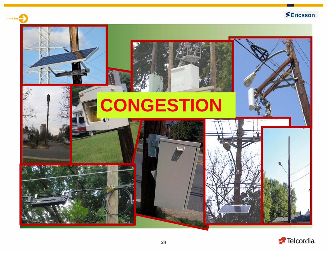
Congestion On Poles
In Buried Locations
In Underground Facilities
(ducts, conduits, vaults…)
Urban versus rural areas
Power, water, …. other utilities
A broad definition of “joint use” includes facilities near, adjacent, and in the vicinity of the telecom plant
Drive for new technologies – wireless, broadband, new builds and so forth helps increase density of interconnected devices and facilities Smart grid devices, Wireless – antennas, power supplies etc…, Security devices for control and surveillance, Traffic lights, Luminaries, Light rail and so forth
Depths and Order of Buried Plant
Ericsson

26
WIRELESS ANTENNAS ….
Strength of Support Elements
Vertical Conductor Protection
Obstructions to Working SpaceRF Radiation Hazards
Clearance from Supply Line Conductors
Ericsson

27
Code Scope and Demarcation
Harmonization, Demarcation, and Competition, Between Codes
----------------------------------Joint Use
Competition -- Cooperation
Ericsson

28
Code Scope Boundaries Supply Equipment in Communications Space Definitions
“Supply” and “Communications” equipment Communications Worker Safety Zone (CWSZ)
Limits for communications plant Power limited circuits
Wind and Solar panel farms
Ericsson

29
Themes and Trends Demarcation between Codes and Standards -
NESC/NEC/GO95…local codes Codes are not in significant technical conflict over general objectives
and intent – However the “Devil is in the Details” Local interpretations vary greatly between inspectors, local
authorities, and individual utilities generate conflicts Other (Hidden) Agendas – Business and Economic Drivers,
Regulatory and Local /State/Federal Political Factors
Ongoing Refinements to make code practical and usable Conflicts around Congestion Issues Communications (Lack of ?) Between Stakeholders
Cooperation between all Joint users of structure and Right-of-Ways
Ericsson
30
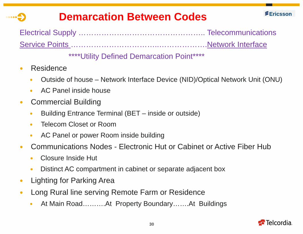
Demarcation Between CodesElectrical Supply ………………………………………….. TelecommunicationsService Points ……………………………..……………….Network Interface
****Utility Defined Demarcation Point**** Residence
Outside of house – Network Interface Device (NID)/Optical Network Unit (ONU) AC Panel inside house
Commercial Building Building Entrance Terminal (BET – inside or outside) Telecom Closet or Room AC Panel or power Room inside building
Communications Nodes - Electronic Hut or Cabinet or Active Fiber Hub Closure Inside Hut Distinct AC compartment in cabinet or separate adjacent box
Lighting for Parking Area Long Rural line serving Remote Farm or Residence
At Main Road……….At Property Boundary…….At Buildings
Ericsson

31
Other Codes and Regulatory Influences e.g., California GO 95 …… FCC ....)
Multiple Purposes of Codes Safety to Workers and Public Regulatory and Legal Compliance – Risk Management Engineering – help ensure practical and useful rules to facilitate safe Joint Use
installations and work rules Continued communications in times of disaster and emergency
LRFD versus ASD Engineering designs Safety Factors Load Calculations Worst case situations Vs. “Expected” stress
“Will Not Fail” Precision of Legal/Regulatory Language Engineering Reality
Continuity of Communications including Cellular Service Backup reserve power Duplicate routes During/after Wild Fires
Ericsson

32
Risk Management
InspectionsTests
Responsibilities
(Legal, Regulatory, Service Availability)
Ericsson

33
Risk Management - Work Rules
Tests and Inspections (Rules 214 & 313)
Conditions versus Defects
Routine inspections during other work vs. separate program
Maintenance and Activity around Batteries DC Circuits - Arc Flash Risks, Protection and PPE Aerial Lifts Clearances, separations, buried depths,
Ericsson

34
Operational Concerns in Legal Cases Inspections
Incidental to Regular Work Activities Separate Inspection Programs (Frequency?) Can be Regulatory or legally driven
Documentation and Records Trouble Report Calls - Response times and Access to Data Installation/Maintenance/Repair Engineering and Design Records - Pole Loading Analysis
Practices Routine inspections for safety of workers and public Corrections of Defects and Reporting of Conditions Differences in Operations between utilities – e.g., use of metallic
versus dielectric buckets on truck
Ericsson

35
Batteries -- Rule 420G activity
Concerns raised during NESC discussions with Working Group at moment 1.The battery rules Rule 420G and Rule 140 need updating
2.DC Arc Flash risk needs NESC reference Current 420G rules are appropriate and adequate Could revise title of Rule 420G to read one of the following
“Flooded, Absorbed electrolyte and Gel-Electrolyte Batteries” “Liquid-Cell and Gel-cell Batteries” “Batteries”.
One could add an informational note in Rule 420G pointing the user to Rule 140 for appropriate rules covering “large flooded type cells; e.g., Lead-Acid Round Cells”.
Ericsson

36
Telecom Batteries Flooded CO Batteries Require watering and maintenance. Rule 140 criteria are appropriate for theses cells and usually met through the
internal and normal work practices and procedures The power rooms have controlled access and ventilation VRLA Batteries in OSP (huts and cabinets) Controlled access (doors) to huts and battery spaces Plastic shields prevent accidental contact with terminal posts. These barriers also
provide a guard/cover in the unlikely instance that gas or liquid is vented from the VRLA (Lead-Calcium) type batteries. Designed to require minimal maintenance – incidental inspection with visual
monitoring for any signs of leakage, and measured for their state of charge. Any problems found are referred to battery maintenance personnel with appropriate
training and tools (including PPE) to replace the batteries if needed.Other Battery Types VRLA (TTPL = Thin Plate Pure Lead), and gel cells Ni-Cd (Nickel-Cadmium) or NiCad NiMH = Nickel Metal Hydride – Na-Ni-Cl = Sodium Metal Hydride Li-ion – lithium ion technologies - LCO, NCA, LFP, Lithium Cobalt Oxide
Ericsson
37
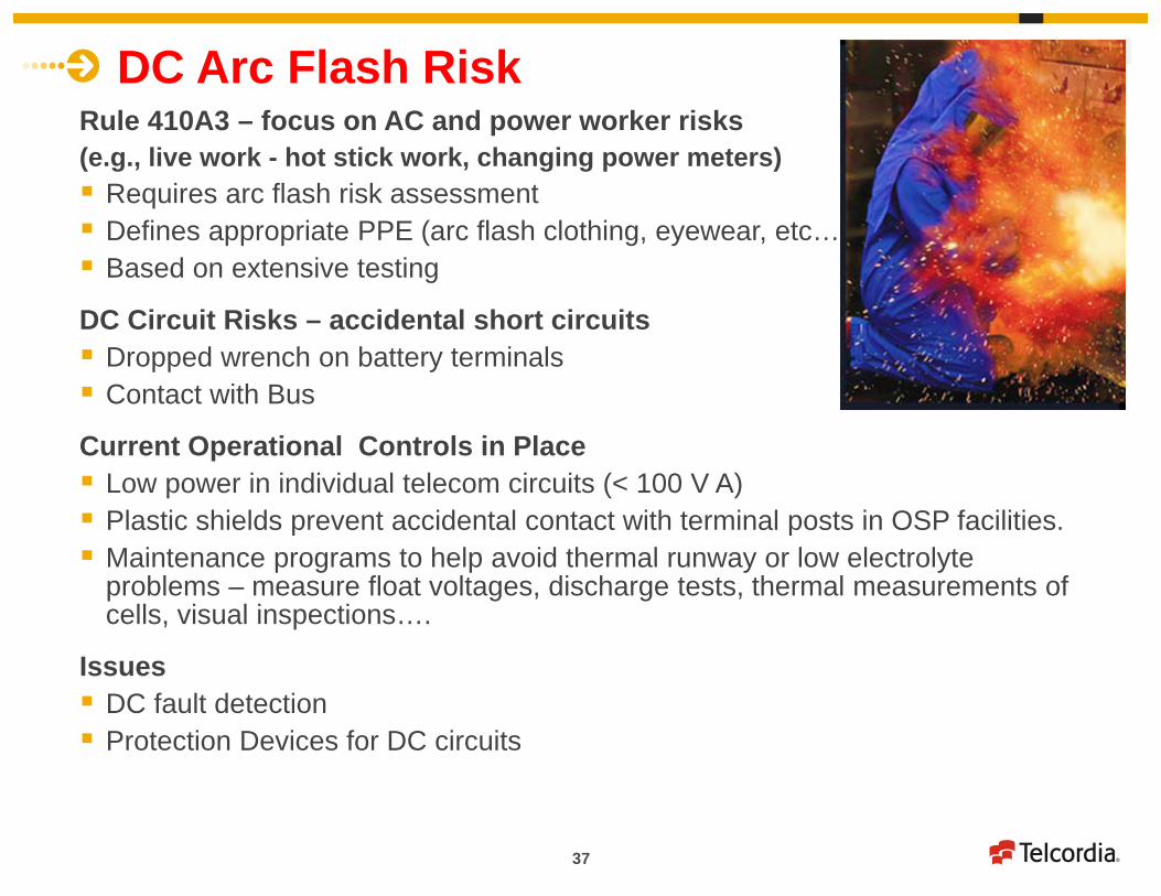
DC Arc Flash RiskRule 410A3 – focus on AC and power worker risks (e.g., live work - hot stick work, changing power meters) Requires arc flash risk assessment Defines appropriate PPE (arc flash clothing, eyewear, etc…) Based on extensive testing
DC Circuit Risks – accidental short circuits Dropped wrench on battery terminals Contact with Bus
Current Operational Controls in Place Low power in individual telecom circuits (< 100 V A) Plastic shields prevent accidental contact with terminal posts in OSP facilities. Maintenance programs to help avoid thermal runway or low electrolyte
problems – measure float voltages, discharge tests, thermal measurements of cells, visual inspections….
Issues DC fault detection Protection Devices for DC circuits
Ericsson

38
Aerial LiftsIssue = Continued incorrect contention that metallic lifts are more dangerous then “all dielectric” lifts proposal to prohibit these metallic lifts was defeated but the issue will return.
Operational Facts(a) Contact between the person and live energized line/equipment is the danger and the conductivity of the bucket infrastructure is not a critical factor, (b) Buckets with fiberglass/dielectric coverings still have underlying metallic superstructure with electric controls in bucket (i.e., the bucket is not electrically isolated), and (c) Contact occurs because the worker has not followed industry rules and best practices for safe operations. (d) Lift telescopic boom design (contracts in and out in a linear fashion) improves safety factor - boom always below the aerial lift in contrast of some older fiberglass buckets designs.(e) Many fiberglass buckets not as sturdy or resilient as the steel buckets(f) Telecom aerial lifts usually need 110/120 V outlets to operate tools –any bucket with electrical outlet can not be considered “insulated from power”.
.
Ericsson

39
Metallic buckets have the necessary strength required for best construction work practices. Construction line operations require a sturdy constructed truck to perform heavy line operations often while worker is in bucket and truck is moving from pole to pole : Placing strand under tension Placing self-support cable under tension Placing cable using direct cable lasher method. Performing pole transfers – moving cable plant from old pole to new
The aerial lift is often used as a tool to help operator perform work - e.g., a rope winch line is operated from the lift help pull lashers while placing cables. When following usual operational safety rules and work rules, the metallic buckets are safe. Mandatory rules for use of communications lifts that apply regardless of the aerial lift type include: Mandated use of safety harness with double locks for bucket doors Use of insulated gloves when working near foreign power Stay outside of MAD and safe working distances from supply equipment Double chuck rear wheels to prevent the truck from rolling 2-way communications link between the driver and the person in the bucket
EricssonWhy metallic buckets are preferred: 40+yrs experience

40
Ericsson
Clearance and Separation

41
Supply Equipment in Telecom Space
Safety Code Requirements = Baseline or Minimum Level Adequate bonding and grounding to help prevent induced
and fault voltages/currents on the communications circuits. Identification and marking rules to provide equipment or
contact information to help identify responsible party.
Adequate Ground clearance rules. Providing sufficient climbing space Provide sufficient working space around
communications lines and facilities Keep minimum clearances as per the NESC to
help maintain the integrity of the CWSZ around communications facilities.
Ericsson

42
Clearance and Separation NESC are safety driven guidance rules (minimum)On congested Poles - Business and regulatory driven considerations for
growth
Clearances over specific cases
Driveways – service drops to “low” roofs
Water bodies
Roads where newer and larger harvesters and vehicles may pass under
Long spans across roadways where ice loading may be problem (WG)
Fences with overhanding aerial facilities from adjacent or nearby poles
Simplify and clarify calculation of minimum separation between adjacent or crossing communications lines (Rule 235H and 235I)
Separation from rail beds, railroad right-of-ways, agricultural areas, irrigation zones, ….
In joint use applicationsUrban congested environments – microtrenching and microducts
Ericsson

43
Pole Loading and Strength Safety Factors
and Design Principles
Ericsson

44
Pole Loading and Strength Pole Strength and Loadings – GO-95 Vs. NESC approaches Load & Resistance Factor Design (LRFD) Vs. Allowable Strength Design (ASD)
Load and material strength factors along with load duration effects
Extreme Wind methodology and Ice Loading Factors
Correlation with ANSI O5.1 & ASCE (ASCE 7)
Engineered materials; e.g., Fiber-reinforced polymer & concrete structures
Engineering Reality Vs. Regulatory/Legal Language - “..will not fail…”
Design Pole strength for heavy loads – weather events (ice/storm/..)
50…100 year storm or event
Increased reliability (perceived) by over-building poles through
Increased safety factors
Increase replacement criteria (67---75—85—95% strength retention)
Design options and approaches do not necessarily match threats Ice….wind…fire…termites…
Engineering Analysis & Theory versus real world data and experience
Ericsson
45
Code Overview and Background Codes - NESC…GO 95…NEC….OSHA…. Best Practices – Personal Safety & Facilities Reliability Engineering Design for Efficient & Reliable Operation
Issues Bonding & Grounding Congestion – on Poles and in Buried locations Scope Boundaries of NESC/NECWork Rules - Tests and Inspections Clearances Pole Loading and Strength
Plans and Paths Forward - 2014/2015 NESC Preprint Blue Book Revision (Issue 6)
Ericsson

46
Network and Business Drivers More connected and interconnected devices
Smart grid, distributed power systems, antennas, …
More Wireless - More DAS systems’
Higher voltages and power More joint use in broadest terms – near, adjacent,
in close proximity, same pole, trench ort duct Facilities served by both telecom & power lines
Resulting Concerns
Bonding and Grounding
Protection – primary, secondary, tertiary….
Harmonization/coordination of multiple protection devices and strategies
Safety
Equipment
Workers and public
Equipment Performance (S/N and Interference)
Ericsson

47
Expansion of Wireless Networks
From Telcordia GR-3171
Ericsson

48
Transition ofWireless Networks
From Telcordia GR-3171From Telcordia GR-3171
Joint Feeds to Antenna• Power (AC/DC) • Communications (Fiber/Copper)
Antenna Locations• Poles• Towers• Roof Tops• Church Spire• Walls• DAS Indoor
Ericsson

49
Paths Forward: Telecom Perspective -1
A.Review NESC Pre-Print Review Consequences of Changes to Code such as
Definitions Grounding rules 096C and 097G and 384 Buried Plant and Joint use rules 224B, 344, 354D
Are reversal of proposed changes required or further comments and revisions needed?
B.Continue to review Incidents, Accidents and Current Practices for Operations, Personnel and Equipment Facilities Identify Root-Cause Problems Determine Areas for Changes or Improvements (Code or other)
Ericsson
50
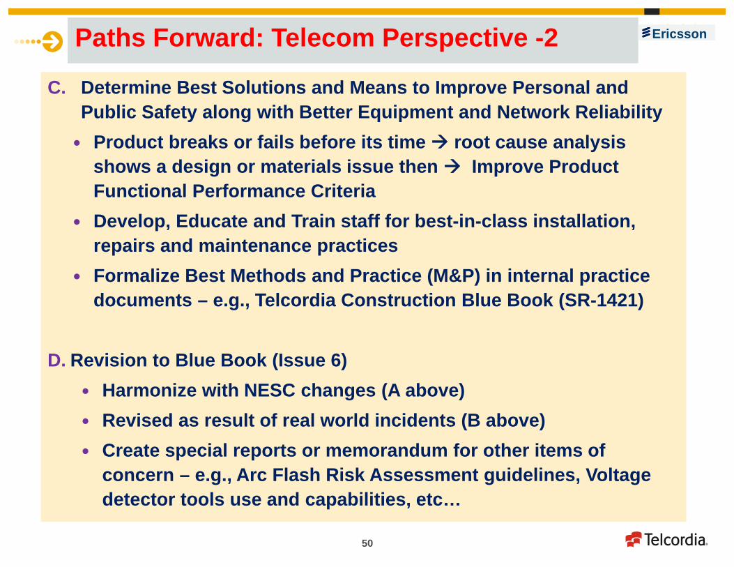
Paths Forward: Telecom Perspective -2
C. Determine Best Solutions and Means to Improve Personal and Public Safety along with Better Equipment and Network Reliability Product breaks or fails before its time root cause analysis
shows a design or materials issue then Improve Product Functional Performance Criteria
Develop, Educate and Train staff for best-in-class installation, repairs and maintenance practices
Formalize Best Methods and Practice (M&P) in internal practice documents – e.g., Telcordia Construction Blue Book (SR-1421)
D. Revision to Blue Book (Issue 6) Harmonize with NESC changes (A above) Revised as result of real world incidents (B above) Create special reports or memorandum for other items of
concern – e.g., Arc Flash Risk Assessment guidelines, Voltage detector tools use and capabilities, etc…
Ericsson

51
Safety Codes Alone Are Not Enough
Baseline for Safety -- NESC…OSHA….NEC… GO 95Limits of Safety Codes 5 year cycle slow to respond to market/business initiatives
3 year cycle like NEC ? Still too slow ? TIA process? conservative process--takes time--requires >75% agreement Develop local perturbations – Legislative, PUC, BPU, California GO95, etc…
A.Design, Engineering and Product Specifications B.Operational M&Ps and Engineering Controls
Industry or Individual Company Driven ATIS – STEP, PEG … ATIS-0600333, etc… Telcordia GR-1089, SR-1421, GR-3171, etc… IEEE-516, IEEE-P487, UL-609590, IEC, … Supplier product specific engineering/use guidance
Ericsson

52
NESC Alone is Not Enough Safety Codes…….Regulatory and Legal Mandates NESC…NEC..OSHA…GO 95…. Local and Regional Building and Fire Codes
Internal Practices Telcordia Construction Blue Book – Issue 5 (2011).., new issue in 2014 Service Providers - ATT..Verizon… Centurylink … RUS.. Manufacturer/Supplier provided instructions and guidance documents
Product Specifications and Functional Performance Criteria Poles & Hardware - GR-60 Wood, GR-3159 Non-Wood, GR-3174 Hardware Equipment - Physical Protection -- GR-3108… GR-1089 EMC…..GR-63 and
most recently GR-3171 - OSP Network Elements Used in Wireless Networks Enclosures and Closures - GR-43 (Huts), GR-487 (Electronic Equipment
Cabinets), GR-950 (ONUs), GR-902 (Handholes) Cables, .GR-421, GR-3163, GR-3164, GR-137, GR-492, GR-20, etc..….
Design Engineering for Network Reliability and Long Lifetimes --- 20…..40 years Quality and Availability of Services (99.999+%)
Safety Codes Not Enough Ericsson

53
General ScopeChapters 1 and 2
Aerial PlantChapters 3 –to-14
Underground & Buried PlantChapters 15 - to - 25 Chapter 26-27-Appendices
Internal Practices – e.g., Telcordia Construction Blue Book (SR-1421)
Scope, Purpose and List of Changes Coordination with Other Codes and Standards General Safety Precautions and Guidelines
Working in Vicinity of Power Conductors Minimum Approach Distances, Arc-Flash… Visual Pole Inspection. Buried Plant Precautions and Manholes Fiber Optics
Inspection and Make-Ready Survey Checklists
Clearances Strand Pole Line Hardware Guying Insulating Guys Anchors and Guy
Rods Suspension Strand
Bonding and Grounding
Aerial Markers Pole Testing and
Inspection Pole Strength Supply Equipment
in/near Telecom Space
Buried Plant General Construction High-Speed Blown
Cable Direct Buried Duct Directional Drilling Bonding Drop Cable Placing Cable
Guards
Manholes General Precautions Testing Atmosphere
and Ventilating Bonding Cables Cable Markers Sealing Ducts and
Conduits
FTTx Deployments Symbols for Grids and Mapping Diagram Appendices Background on Ice-Wind Load Map used for
Reliability-Based Design of Required Pole Strength
NESC 2012-2017 Cycle Schedule NESC Active Issues – Working Groups (WGs)
Ericsson

54
Blue Book Revisions and UpdatesFormal Blue Book or Proprietary Reports - 1
1. Harmonize with changes expected to occur in 2017 NESC2. “Make-Safe”– defining and expanding on procedures around the term
“make-safe” including items for cooperation and joint use agreements between telecom, power and other utilities. This will include guidance on desirable cooperation between local work center managers (the “responsible persons”) versus a formal agreement or contract.
3. Grounding and Bonding – issues as covered here in this presentation4. Drop Plant Attachment, Separation and Clearance – best practices for
aerial and buried service wires to single residences, multi-dwelling (MDU) units, and appropriate use (if any) of telecom cables in conduit, air shafts, elevators shafts and other non-standard places.
5. Antenna and Wireless Applications – review and update aspects of this expanding plant regarding such GR-3171 issues such as radiation hazards, working space & climbing space, locations (towers, poles, roof tops, belfries, Inside building), for DAS systems, inside CO areas
6. Congestion – what are the best practices and options for such situations as the develop on poles and below ground
Ericsson

55
Blue Book Revisions and UpdatesFormal Blue Book or Proprietary Reports - 2 7. Excavation Hazards and Precautions with discussions on - One call
systems (811) , Working practices near marked lines, Hand work with shovel versus machine excavation – back-hoe, direction drilling, fiber placement - burial depth for safety and to minimize service disruption Civil Works - excavation and structural issues near buildings and
structures; e.g., appropriate trenching and separation requirements Manholes – update sections for handholes/vaults (GR-902)
8. Risk Management – provide suggested and recommendation practices and processes in case of possible disputes – cooperation vs.. joint use agreements versus legal conflicts.. Include suggested minimum inspection frequencies for facilities
9. Revisions of pole strength and loading chapters10.Aerial Bucket Practices – practices for using open metal basket vs..
closed covered bucket vs. “all dielectric” bucket aerial lifts 11.Hardware Chapters - update with guidance in GR-3174
Ericsson

56
Q & A
THANK YOU
Contact:
Trevor N. Bowmer, Ph.D.Senior Analyst - TelcordiaNetwork & Product [email protected]. 732.699.3341
Ericsson

57
Additional InformationFor
Reference
Ericsson
58
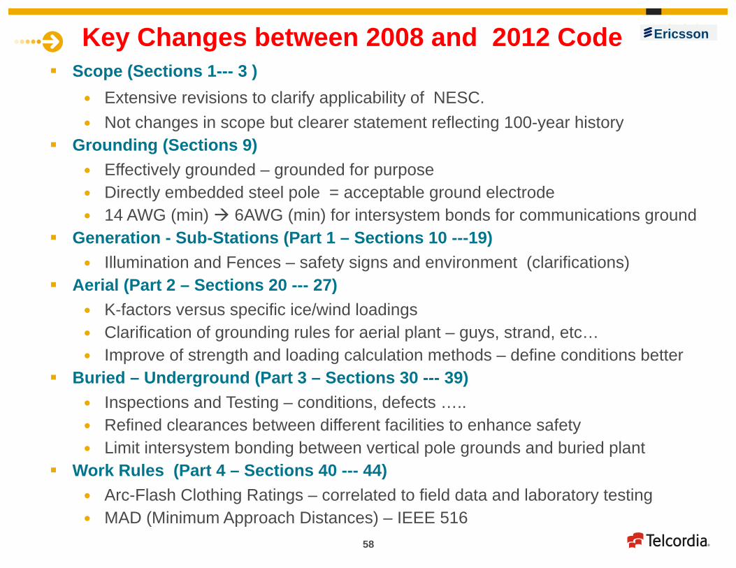
Key Changes between 2008 and 2012 Code Scope (Sections 1--- 3 )
Extensive revisions to clarify applicability of NESC. Not changes in scope but clearer statement reflecting 100-year history
Grounding (Sections 9) Effectively grounded – grounded for purpose Directly embedded steel pole = acceptable ground electrode 14 AWG (min) 6AWG (min) for intersystem bonds for communications ground
Generation - Sub-Stations (Part 1 – Sections 10 ---19) Illumination and Fences – safety signs and environment (clarifications)
Aerial (Part 2 – Sections 20 --- 27) K-factors versus specific ice/wind loadings Clarification of grounding rules for aerial plant – guys, strand, etc… Improve of strength and loading calculation methods – define conditions better
Buried – Underground (Part 3 – Sections 30 --- 39) Inspections and Testing – conditions, defects ….. Refined clearances between different facilities to enhance safety Limit intersystem bonding between vertical pole grounds and buried plant
Work Rules (Part 4 – Sections 40 --- 44) Arc-Flash Clothing Ratings – correlated to field data and laboratory testing MAD (Minimum Approach Distances) – IEEE 516
Ericsson

59
Grounding of Guys and Support HardwareNESC Rule 215 requires a guy to be effectively grounded or isolated.Intentions of Rules 215 & 233 is to make sure that if a line conductor or guy goes slack then fault current/voltage will not expose the public, supply/communications workers or equipment to power. Telecommunications guys are presently electrically bonded through their
attachment hardware . The grounding path can include Anchors Strand Through the pole attachment hardware Vertical pole ground wires (MGNs) 4 grounds in a mile (Rule 97)
The telecom equipment is "effectively grounded” since there is a permanent bond to the pole ground and supply neutral. A solidly attached guy forms a low resistance connection to earth through the attachment hardware, strand and MGN connections. The interconnected system meets the definition of effectively grounded since it is “designed to minimize hazard to personnel and having resistances to ground low enough to permit prompt operation of circuit protective devices”.
Ericsson

60
Note (1) defined by application and available space – 8 or more feet desired for 8 foot rods.
Note (2) – crimped or welded connection using a 2-hole/lug ground connector is preferred Crimp/weld better electrical and
mechanical bond Screw-type more easily reconfigured.
Note 3 – Rods shall be 8 feet minimum length and 5/8-inch diameter for iron/steel, or ½ inch diameter of stainless steel or copper-clad stainless-steel.
Telecom Grounding Bed –Ground Rod System
Should be #6 AWG 2 feet from Pole buried 12 inches
Improper Rod Placement
Ericsson