nasa goddard’s testing philosophy panel discussion · nasa goddard’s testing philosophy panel...
TRANSCRIPT

August 21, 2003 NASA/GSFC Summary 1
NASA Goddard’s Testing PhilosophyPanel Discussion
Carol L. MosierCode 545
ASTROE2, MAP, WIRE, TRACE, SMEX LITE, ASTROE1, CASSINI, UARS, SIRTF, COBE
August 21, 2003 NASA/GSFC Summary 2
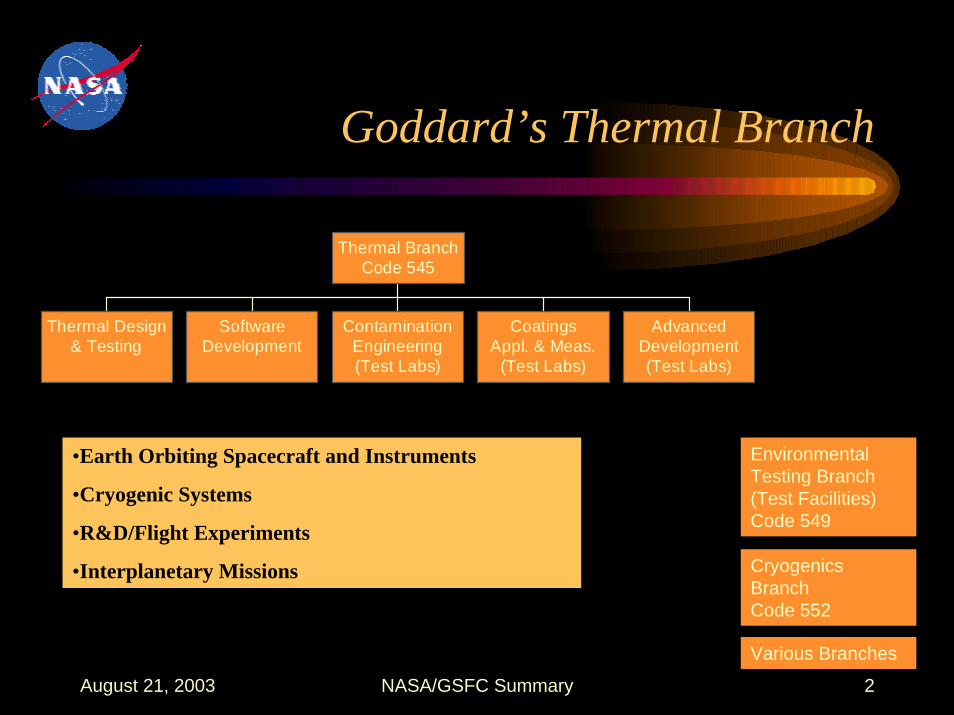
Goddard’s Thermal Branch
Thermal Design& Testing
SoftwareDevelopment
ContaminationEngineering(Test Labs)
CoatingsAppl. & Meas.
(Test Labs)
AdvancedDevelopment(Test Labs)
Thermal BranchCode 545
Environmental Testing Branch (Test Facilities) Code 549
•Earth Orbiting Spacecraft and Instruments
•Cryogenic Systems
•R&D/Flight Experiments
•Interplanetary Missions Cryogenics Branch Code 552
Various Branches

August 21, 2003 NASA/GSFC Summary 3
Goddard’s Testing Philosophy
• Goddard has a guideline called the General Environmental Verification Specification (GEVS). However a project may modify all test requirements.
• Three different levels of assembly:– Unit/component– Subsystem/instrument– Payload/observatory

August 21, 2003 NASA/GSFC Summary 4
Goddard’s Testing Philosophy
• In General, component temperature should NEVER exceed what they’ve experienced in the previous level of test.
• Proto-flight and Qualification temperature levels are the same.
• Acceptance testing rarely applies. Levels specified in GEVS.
August 21, 2003 NASA/GSFC Summary 5
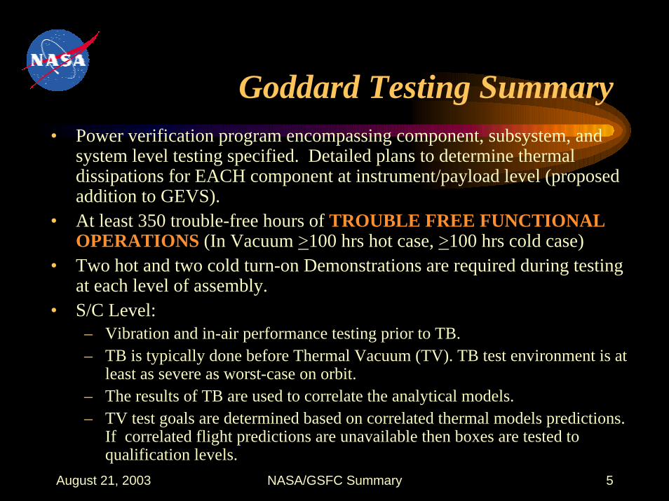
Goddard Testing Summary• Power verification program encompassing component, subsystem, and
system level testing specified. Detailed plans to determine thermal dissipations for EACH component at instrument/payload level (proposed addition to GEVS).
• At least 350 trouble-free hours of TROUBLE FREE FUNCTIONAL OPERATIONS (In Vacuum >100 hrs hot case, >100 hrs cold case)
• Two hot and two cold turn-on Demonstrations are required during testing at each level of assembly.
• S/C Level:– Vibration and in-air performance testing prior to TB.– TB is typically done before Thermal Vacuum (TV). TB test environment is at
least as severe as worst-case on orbit. – The results of TB are used to correlate the analytical models.– TV test goals are determined based on correlated thermal models predictions.
If correlated flight predictions are unavailable then boxes are tested to qualification levels.

August 21, 2003 NASA/GSFC Summary 6
Thermal Vacuum - GEVS Summary
Vacuum Thermal Cycles
Dwell Time at Extremes
Thermal Margins Assembly Level
<10-5 Torr
Four >24 hours
+ 10o C beyond worst-case flight predictions. Heater controlled systems can be changed to -5o C if there is verified active control.
Payload
<10-5 Torr
Four > 12 hours + 10o C beyond worst-case flight predictions. Heater controlled systems can be changed to -5o C if there is verified active control.
Subsystem/ Instrument
<10-5 Torr
Eight >4 hours
Qualification Limits (usually + 10o C of flight operational limits) . Heater controlled systems can be changed to -5o C if there is verified active control.
Component/ Unit

August 21, 2003 NASA/GSFC Summary 7
Testing Special Cases
• Temperature margin, number of cycles, and dwell time for cryogenic systems are specific to the project.
• If expected mission temperature excursions are small (less than 10o C) or the transition times are long (> 72 hours) the number of cycles at payload level may be reduced to two. However dwell times at plateaus must be doubled.
• For Small payloads, such as SMEX class, the durations may be shortened, if appropriate.
• Components that are insensitive to air effects may be tested at ambient pressure. The number of thermal cycles are increased by 50%, minimum dwell time 6 hrs (proposed GEVS), and +15oC thermal margin (+25oC proposed GEVS) .

August 21, 2003 NASA/GSFC Summary 8
Heater Verification PhilosophyVerify operation, thermostat/software set points, and margin.
System in the minimum power mode at minimum bus voltage and with the worst-case cold environment.
• CRITERIA 1 – Control point of heater slightly above allowable temperature – Less than 70% duty cycle
• CRITERIA 2 (proposed GEVS)– Control point of heater > 10oC above allowable temperature– Heater can be fully saturated (100% duty cycle)
Note: No extra ordinary measures will be taken to get a heater to turn on if it didn’t come on during testing because its temperature never dropped below thermostat set-points.

August 21, 2003 NASA/GSFC Summary 9
Active Control Systems Philosophy
• Some examples of actively controlled systems are Heaters, Loop Heat Pipes, Capillary Pumped Loops and TECs.
• Criteria for Systems with Variable Set-Points* – A test temperature margin of no less than 5°C shall be
imposed on the respective band that is under control– System maintains control
• Criteria for Systems with Non-Variable Set-Points * – Environment set to decrease/increase heat load by >30%– System maintains control
*(proposed GEVS)

August 21, 2003 NASA/GSFC Summary 10
Soak Criteria, Transition Rates, and Thermal Stability
• Temperature soaks shall begin when the “control” temperature is within +2o C of the goal.
• The rate of transition during warming or cooling shall be specified to ensure stresses caused by the thermal gradients will not damage the test article. Contamination effects may be a factor in transition rates. In general, transition rates should be at least as severe as seen in flight.
• TB Stabilization criteria: ∆T < 0.05° C/hr for >6 hrs and exhibit a decreasing temperature slope over that period OR the ∆Q is a small fraction (typically 2 to 5%) of the total energy of the test article.

August 21, 2003 NASA/GSFC Summary 11
Sample Problem Statement
• An externally mounted power distribution box (PDB) dissipating 36 watts (nominally) is predicted to swing between -5o C and 34o C for a low-earth orbit 5-year mission.
• In safe-mode, the unit only operates at 8 watts and requires heaters to control the unit to -15o C which are controlled via bimetallic thermostats between -15oC and -5oC on a survival bus operating between 24V and 32 V. The designer-supplied operational limits are -20oC to +45oC and survival limits -20o C to 50o C.

August 21, 2003 NASA/GSFC Summary 12
Sample Problem Assumptions
• It was assumed that the designer supplied operating limits (-20oC to +45oC) were the allowable min/max temperatures when the box is operating (qualification/ proto-flight temps). The min/max temperatures when the box is non-operating was assumed to be the survival limits (-20oC to +50oC).
• Goddard would set the FLIGHT Operating limits at -15oC (heater controlled) to +35oC. The FLIGHT non-op limits would be (-20oC to +50oC).
August 21, 2003 NASA/GSFC Summary 13
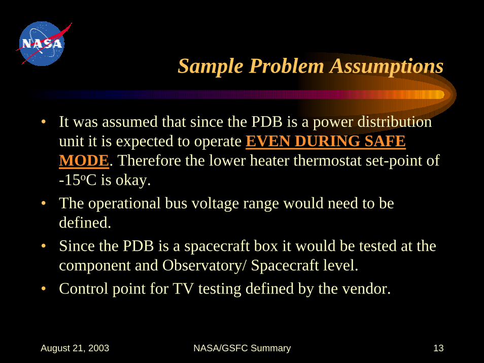
Sample Problem Assumptions
• It was assumed that since the PDB is a power distribution unit it is expected to operate EVEN DURING SAFE MODE. Therefore the lower heater thermostat set-point of -15oC is okay.
• The operational bus voltage range would need to be defined.
• Since the PDB is a spacecraft box it would be tested at the component and Observatory/ Spacecraft level.
• Control point for TV testing defined by the vendor.

August 21, 2003 NASA/GSFC Summary 14
Sample Problem -Component Level Testing
Step 3: Performance testing at box level in Vacuum
• Eight cycles in Vacuum
•-20 to +45 C while operating
•Performance Testing during all transitions & plateaus
•24 to 32 Volts (plus operational voltage range for at least one cycle)
•4 hour dwells at plateaus
•Power measurements at plateaus
•Cold and hot turn-on (2x)
•Contamination Bake-out
Step 1: Create Analytical Model of PDB (box held as a boundary temp. of -20 to +50 C) and iterate on design until junction/ case temperatures of all components are acceptable.
Step 2: performance testing at ambient conditions done prior to vacuum testing

August 21, 2003 NASA/GSFC Summary 15
Sample Problem Component Level Thermal Vacuum Test Profile
Evacuate Chamber
Cold Plateau 1 Cold
Turn on
Hot Plateau 1 Hot Plateaus
2-7
Hot Turn on
Contamination Bake-out
50 C
-20 C
45 C
Cold Plateaus 2-8
Hot Plateau 8
Turn off Turn
off
50 C
Hot Turn on
Cold Turn on
Turn off
August 21, 2003 NASA/GSFC Summary 16
Sample Problem -S/C Level Testing
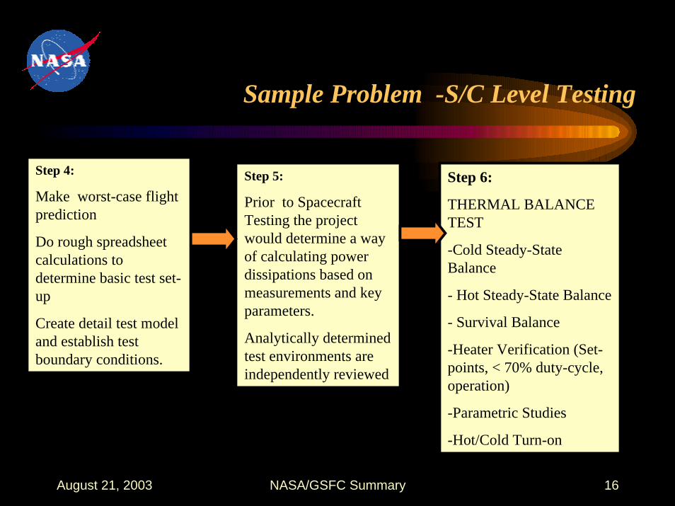
Step 5:
Prior to Spacecraft Testing the project would determine a way of calculating power dissipations based on measurements and key parameters.
Analytically determined test environments are independently reviewed
Step 6:
THERMAL BALANCE TEST
-Cold Steady-State Balance
- Hot Steady-State Balance
- Survival Balance
-Heater Verification (Set-points, < 70% duty-cycle, operation)
-Parametric Studies
-Hot/Cold Turn-on
Step 4:
Make worst-case flight prediction
Do rough spreadsheet calculations to determine basic test set-up
Create detail test model and establish test boundary conditions.
August 21, 2003 NASA/GSFC Summary 17
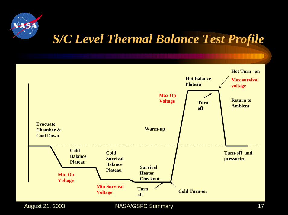
S/C Level Thermal Balance Test Profile
Evacuate Chamber & Cool Down
Cold Balance Plateau
Cold Survival Balance Plateau Survival
Heater Checkout
Warm-up
Cold Turn-onMin Survival Voltage
Min Op Voltage
Hot Balance Plateau
Max Op Voltage Return to
Ambient
Turn-off and pressurize
Hot Turn –on
Max survival voltage
Turn off
Turn off
August 21, 2003 NASA/GSFC Summary 18
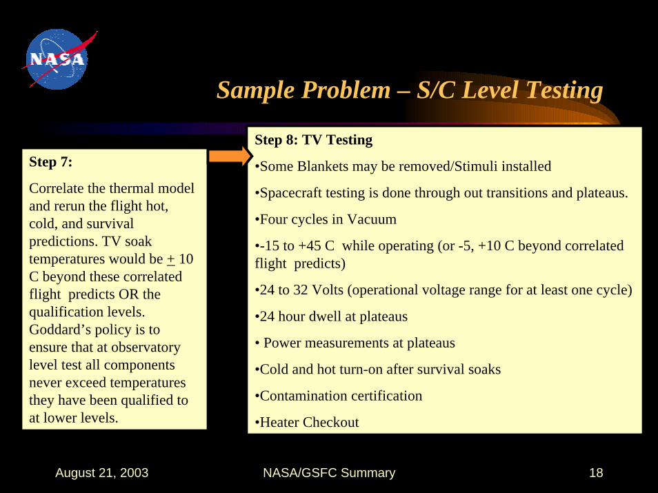
Sample Problem – S/C Level Testing
Step 8: TV Testing
•Some Blankets may be removed/Stimuli installed
•Spacecraft testing is done through out transitions and plateaus.
•Four cycles in Vacuum
•-15 to +45 C while operating (or -5, +10 C beyond correlated flight predicts)
•24 to 32 Volts (operational voltage range for at least one cycle)
•24 hour dwell at plateaus
• Power measurements at plateaus
•Cold and hot turn-on after survival soaks
•Contamination certification
•Heater Checkout
Step 7:
Correlate the thermal model and rerun the flight hot, cold, and survival predictions. TV soak temperatures would be + 10 C beyond these correlated flight predicts OR the qualification levels. Goddard’s policy is to ensure that at observatory level test all components never exceed temperatures they have been qualified to at lower levels.

August 21, 2003 NASA/GSFC Summary 19
S/C Level Thermal Vacuum Test Profile
Evacuate Chamber & Cool Down
Cold Survival Plateau 1 & heater checkout
Cold Turn on
Hot Plateau 1 Hot
Plateau 2Hot Plateau 3
Hot Plateau 4
Cold Plateau 2
Cold Plateau 3
Cold Plateau 4
Hot Turn on
Min. Survival Voltage
Out gassing Certification
50 C
Max. Survival Voltage
-20 C
-15C*
45 C*
* Or flight predict+ plus margin

August 21, 2003 NASA/GSFC Summary 20
Summary
• The next steps would be to adjust radiator sizes and reinstall blankets. If there were significant changes a second thermal balance test may have to be performed. If there were significant repair work then a second TV test may need to be performed.
• GSFC Facilities– Center’s Thermal (Ed Packard, Code 549, 301-286-6058)– Thermal Branch’s (Jentung Ku, Code 545, 301-286-3130)– Cryogenics Branch’s (Howard Branch, Code 552, 301-286-5405)