naacc stream crossing survey data form instruction guide for... · naacc stream crossing survey...
TRANSCRIPT
NAACC Stream Crossing Survey Data Form
Instruction Guide
Developed by the
North Atlantic Aquatic Connectivity Collaborative
Including: University of Massachusetts Amherst
The Nature Conservancy
U.S. Fish and Wildlife Service
Version 1.1 – May 2015
CONTACTS
Scott Jackson
Department of Environmental Conservation
Holdsworth Hall
University of Massachusetts
Amherst, MA 01003
(413) 545‐4743; [email protected]
Alex Abbott
Gulf of Maine Coastal Program
U.S. Fish and Wildlife Service
4R Fundy Road
Falmouth, ME 04105
(207) 781‐8364; [email protected]
For more information, go to: www.streamcontinuity.org.

1
ACKNOWLEDGEMENTS
The development of this instruction guide and the survey protocol it explains would not have been possible without the effort of many people involved with the NAACC. First and foremost, we would like to thank our colleagues from the NAACC Core Group who worked so diligently to develop and refine the concepts reflected here, and the documents resulting from their many days and hours of effort. The core group includes Rich Kirn of the Vermont Department of Fish and Wildlife, Jessie Levine, Erik Martin, and Michelle Brown of The Nature Conservancy, Jed Wright of the U.S. Fish and Wildlife Service Gulf of Maine Coastal Program, Melissa Ocana and Bob English of the University of Massachusetts Amherst, and Keith Nislow of the U.S. Forest Service. We are particularly thankful to Jessie Levine for her many hours of thorough editing.
In addition, the NAACC relies on a Working Group composed of dozens of professionals working across the region in state and federal agencies and nongovernmental organizations dedicated to improving stream connectivity for the health and resilience of our aquatic and terrestrial ecosystems, as well as safeguarding our infrastructure in the face of a changing climate and increasingly intense, and sometimes devastating storms. Thanks to all those who have lent their time and expertise to making our collaborative successful.
And, finally, thanks to the U.S. Fish and Wildlife Service North Atlantic Landscape Conservation Cooperative for
funding this important work.
Alex Abbott & Scott Jackson

2
TABLE OF CONTENTS
OVERVIEW ................................................................................................................................................ 3
SURVEY PLANNING ................................................................................................................................... 4
General Planning ................................................................................................................................... 4
Safety..................................................................................................................................................... 5
Equipment ............................................................................................................................................. 5
Unmapped Sites and Nonexistent Crossings ........................................................................................ 6
COMPLETING THE SURVEY DATA FORM .................................................................................................. 7
Shaded Boxes ........................................................................................................................................ 7
Site Identification .................................................................................................................................. 7
Undisturbed Stream Reference Reaches .............................................................................................. 8
Crossing Data ........................................................................................................................................ 8
Structure Data ..................................................................................................................................... 16
3
OVERVIEW
This document provides guidance for completing the North Atlantic Aquatic Connectivity (NAACC) Stream Crossing Survey Data Form.
The North Atlantic Aquatic Connectivity Collaborative (NAACC) is a network of individuals from universities, conservation organizations, and state and federal natural resource and transportation departments focused on improving aquatic connectivity across a thirteen-state region, from Maine to Virginia. The NAACC has developed common protocols for assessing road-stream crossings (culverts and bridges) and developed a regional database for these field data. The information collected will identify high priority bridges and culverts for upgrade and replacement. The NAACC will support planning and decision-making by providing information about where restoration projects are likely to bring the greatest improvements in aquatic connectivity.
The survey data form is to be used for an entire road-stream crossing, which may include single or multiple culverts or multiple cell bridges. On the first page, the top of the form contains general information about the crossing, and the bottom half of that page is for data on the first (or only) structure at the crossing. Subsequent pages are used to add data where there are additional culverts or bridge cells. It can be difficult to determine how best to evaluate multiple culvert/cell crossings. Please remember that it is essential to gather all of the data required for each structure (pipe or bridge cell) for accurate assessment of the entire crossing.
Stream crossing survey data can be collected digitally on a variety of devices, including tablet computers and smart phones. While data collected digitally must be reviewed before upload to the NAACC database, data upload can be done in “batches” without the need for manual entry. Paper forms can also be used, with subsequent manual data entry to the NAACC online database. Further instructions for data entry by each of these methods is provided in survey training sessions, and at www.streamcontinuity.org.
Please be sure to complete every possible element of the field data form.
4
SURVEY PLANNING
GENERAL PLANNING
Any effort to survey stream crossings should be based on a plan that includes answers to the following key questions:
1. Who is primarily responsible for managing the surveys? Each NAACC state or region will have a coordinator who helps decide on priority areas for survey and how to manage the data once surveys are completed. This coordinator will also plan for, oversee, and collect data from the surveys. Contact Scott Jackson ([email protected]) for more information, or refer to the NAACC website to locate a coordinator in your region: www.streamcontinuity.org.
2. How will surveyors be trained? Training should be arranged through your regional or state coordinator, and includes both classroom and field survey practice. Online training will be available soon and posted on www.streamcontinuity.org. The most important elements of training are becoming familiar with this instruction manual and gaining practice through survey of a variety of crossings with an experienced surveyor.
3. When should surveys be done? Ideally, surveys should be conducted during low-flow periods, particularly summer and early fall.
4. How should we decide where to survey? Consult with your regional coordinator to decide whether surveys will be conducted in one or more watersheds, towns, or counties. Plan to have maps to help you navigate to sites you plan to survey, either copies of existing maps such as the DeLorme Atlas and Gazeteer, or more sophisticated maps from a geographic information system (GIS). When collecting data digitally on a tablet computer or smart phone, survey coordinators must identify and map planned survey sites for your chosen survey area.
For each state in the NAACC region, United States Geological Survey (USGS) HUC-12 subwatersheds have been prioritized for field surveys by the NAACC project team. These subwatersheds were prioritized based on several objectives including brook trout, diadromous fish, and the potential vulnerability of culverts to failure. These prioritized results can be a useful starting place for identifying areas to survey. In addition, there may be locally important watersheds or habitats in your state or region that may help guide location of surveys. To see the NAACC priority subwatersheds in your area, visit the web map at http://arcg.is/1F2rPJu. This web map also depicts road-stream crossings symbolized by their estimated restoration potential which can help focus survey efforts within a subwatershed.
5. Which sites will be surveyed? Work with your state or regional coordinator to decide whether all crossings, or only certain types or sizes of streams will be considered. Some crossing surveys focus primarily on designated perennial streams containing most aquatic habitats, while other survey projects include all ephemeral and intermittent streams. In other cases, certain places in the watershed or town may be identified as highest priority for surveys, based on ecological or other criteria.
6. How will we keep track of the sites visited? You should maintain records, possibly as notations on paper maps, or in a table listing each planned survey site, showing which sites have been surveyed and when. Organize your survey forms by date, and be sure each survey form is complete. Once data has been entered to the NAACC database, you will be able to see all surveyed sites through online maps to verify that you have completed all planned crossings.
7. How can we access crossings on major highways, railroads and private land? Depending on the scope of your surveys, you should have easy access to stream crossings on most public roads, though it is important to be aware of the right-of-way to avoid inadvertently trespassing on private land. Access to interstate highways and railroads is generally much more limited. For cases with limited
5
access to crossings, you are responsible for contacting the appropriate owner or manager of those crossings to request access to conduct surveys. Similarly, for crossings on private roads, you should make concerted efforts to notify private landowners to request permission to conduct surveys on their lands. It may help to work with a local land trust, town or county governments, or state resource agencies to gain access from these landowners, as they often have similar needs for conducting habitat surveys or other resource assessments. In some survey efforts, when allowed by specific laws in effect in those jurisdictions, it has been considered permissible to survey crossings on private roads, particularly if good faith efforts to notify landowners have been undertaken first, or so long as crossings are not on posted or gated roads.
8. How can we be sure our data will lead to crossing improvements? For your data to be useful in setting stream restoration priorities, we encourage you to collect data as completely and accurately as possible and ensure that the data are entered properly into the database. Finally, be sure that all data, including survey forms and site photographs, whether collected digitally or on paper, are transmitted to your state or regional coordinator for archiving.
SAFETY
Streams can be hazardous places, so take care to sensibly evaluate risks before you begin a survey at each stream crossing. While these efforts to record data about crossings are important, they are not nearly as important as your safety and well-being. Working around roads can be dangerous, so be sure to wear highly visible clothing, preferably safety vests in bright colors with reflective material; some vests have the additional bonus of containing many pockets to hold gear. Take care when parking and exiting your vehicle, and when crossing busy roads.
These surveys are best undertaken by teams of two people. This will facilitate taking measurements, making decisions in challenging situations, and recording data.
Take measurements seriously and carefully, but make estimates if necessary for your safety. Avoid wading into streams – even small ones – at high flows and entering pools of unknown depths, and take care scaling steep and rocky embankments. There are usually ways to effectively estimate some dimensions without risk. For example, an accurate laser rangefinder is a safe way to measure longer distances when conditions are unsafe, such as measuring culvert lengths through them instead of across busy roads.
EQUIPMENT
To collect data on stream crossing structures, you will need several essential pieces of equipment for measuring and recording, and some other items to keep you healthy and safe:
Instruction Guide for the NAACC Stream Crossing Survey Data Form (this document) Measuring Implements in feet and tenths (decimal feet rather than inches)
o Reel Tape: For measuring structure lengths and channel widths; 100 feet. o Pocket Tape: Best in 6 foot “Pocket Rod” version with no spring to rust. o Stadia Rod: Telescoping, 13 feet long to measure structure dimensions such as water depth.
Safety Vests: Brightly colored, reflective vests, preferably with lots of pockets to hold equipment, but most importantly to be seen on the road.
Waders or Hip Boots: To stay dry, insulate from cold water, minimize abrasions, and allow access to tailwater pools and deeper streams.
Flashlight: To be able to see features inside long dark structures. Rangefinder (optional): To safely take measurements without crossing structures, busy roadways or
streams; should be accurate to within one foot for adequate data accuracy. Sun Protection: Hat, sunglasses, and sunscreen as needed. Insect Repellent: To protect from annoying or dangerous bites. First Aid Kit: To deal with any minor injuries, cuts, scrapes, etc. Cell Phone: In case of emergency, to coordinate surveys, or to ask questions of coordinators.
6
For Paper Surveys: Stream Crossing Survey Forms: Best printed on waterproof paper. Bring along more than you expect to
use. Even digital surveys should include these in case a digital device becomes inoperable. Clipboard, Pencils & Erasers Stream Crossing Maps: For planning sites to survey, and for recording sites assessed, a DeLorme Atlas and
Gazeteer or similarly accurate and updated set of maps with topography is helpful for navigation. GPS Receiver: Set GPS to collect data in WGS84 datum, with Latitude and Longitude in decimal degrees. Digital Camera: Best if waterproof and shockproof, with sufficient battery power for a full day of
surveying, and capable of storing approximately 100 low to moderate resolution images (approximately 100 - 500 kilobyte stored size, generally less than 1 million pixels–1 megapixel). Include batteries or battery charger, and download cable. A backup memory chip can be very useful to have on hand.
For Digital Surveys: Tablet Computer: Should be waterproof, and preferably shockproof, to be able to survive wet and rugged
field conditions. Various mapping applications can be run to allow navigation to planned survey sites, replacing paper maps. For more information on this method of survey, refer to the NAACC Digital Data Collection User’s Guide available at http://www.streamcontinuity.org/online_docs.htm.
GPS Receiver: If not integral to the tablet computer, an external GPS device will be needed either to connect to the tablet via Bluetooth or wire, or at the least, to be able to provide correct coordinates for entering to the tablet manually.
Stream Crossing Survey Forms: As a backup in case digital devices fail.
UNMAPPED SITES AND NONEXISTENT CROSSINGS
Survey teams may encounter unmapped crossings, or it may be unclear whether a crossing they have found in the field is on their map because its location does not match the map. In most cases, the surveyed crossing should be within 100-200 feet of the planned crossing. Survey teams also may encounter unmapped crossings because either the road was not mapped, as in the case of a road built to serve a new housing development, or because of an error in the road or stream data.
If there is no planned crossing near the site you are assessing, you need to assign a temporary Crossing Code to that crossing. A Crossing Code is composed of the prefix “xy” followed by the latitude and longitude of the site, with decimal degree latitude and longitude values as seven-digit numbers. For instance, a crossing located at 42.32914 degrees north and -72.67522 degrees west, will have the resulting xy code = “xy42329147267522”, followed by the notation: “NEW XY” to indicate that this crossing site must be added to the map.
Conversely, a crossing may exist on the map but not in the field. If you try to navigate to a site and are certain that there is no crossing in the vicinity, you should select the “No Crossing” option for Crossing Type on the field data form. Some crossings may not actually exist due to errors in generating the crossing points. Another possibility is that there may have been a road crossing there at one time, but the crossing has been removed, but may still need to be surveyed to note passage problems. For these sites, you will select the “Removed Crossing” option. Similarly, sometimes an entire stream reach has been moved, particularly underground, in which case you will select the “Buried Stream” Crossing Type.
In all cases where a survey crew either cannot locate a mapped crossing or intends to add a new unmapped crossing, it is essential to check the location carefully to minimize navigation and data collection errors.
7
COMPLETING THE SURVEY DATA FORM
SHADED BOXES
The shading on the data form is intended to make the form easier to follow and complete. The different shading sets off elements related to certain groups of information from others.
SITE IDENTIFICATION
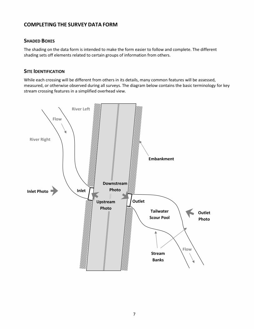
While each crossing will be different from others in its details, many common features will be assessed, measured, or otherwise observed during all surveys. The diagram below contains the basic terminology for key stream crossing features in a simplified overhead view.
Flow
Inlet
Outlet
Tailwater
Scour Pool
River Right
River Left
Inlet Photo
Outlet
Photo
Embankment
Downstream
Photo
Upstream
Photo
Flow Stream
Banks
8
UNDISTURBED STREAM REFERENCE REACHES
When conducting crossing surveys, elements of this data form require you to understand key characteristics of an undisturbed, “natural” section of the stream (called a reference reach) near where the crossing is located. These characteristics include the stream’s approximate width, depth, and velocity, and the type of substrate that predominates there. In general, you will need to go a distance upstream or downstream from the crossing that is between 10 and 20 times the width of the stream to get away from the influence of the crossing. This means for a 10-foot wide stream, you will need to go between 100 and 200 feet upstream or downstream from the crossing to find an undisturbed reach. The distance will be much larger for larger streams. Note that sometimes you will be unable to locate such a reference reach, either because upstream and downstream reaches are too disturbed or modified, or because access is limited, such as by No Trespassing signs.
CROSSING DATA
Complete this section for the entire crossing. Choose only one option for the fields with checkboxes in the crossing data section.
Crossing Code: This is the 18-character “xy code” assigned to each planned survey crossing on survey maps. Be very careful to record the correct numbers, as they represent the precise latitude and longitude of the planned crossing, which can be compared with the actual location you record as GPS Coordinates below.
Date Observed: Date that the crossing was evaluated, following the form M/D/Y.
Lead Observer: The name of the survey team leader responsible for the quality of the data collected.
Town/County: The town or county in which the assessed crossing is located according to the map.
Stream: The name of the stream taken from the map, or if not named on the map, the name as known locally, or otherwise list as Unnamed.
Road: The name of the road taken from the map or from a road sign. Numbered roads should be listed as “Route #”, where # is the route number, with multiple numbers separated by “/” when routes overlap at the crossing (e.g., “Route 1/95”). For driveways, trails, or railroads lacking known names, enter Unnamed.
Road Type: Choose only one option:
Multilane: > 2 lanes, including divided highways (assumed paved) Paved: public or private roads Unpaved: public or private roads Driveway: serving only one or two houses or businesses (paved or unpaved) Trail: primarily unpaved, or for all-terrain vehicles only, but includes paved recreational paths Railroad: with tracks, whether or not currently used
GPS Coordinates: Latitude and Longitude in decimal degrees to 5 decimal places. Use of a GPS (Global Positioning System) receiver is required, but your smart phone or tablet computer may include this capability.
Map Datum: It is best to use WGS84 datum.
Location Format: Use Latitude‐Longitude decimal‐degrees (often in GPS menu as “hddd.ddddd”).
You should stand above the stream centerline, and ideally on the road centerline, when taking the GPS point, but use your judgment and beware of traffic.
Location Description: If there is any doubt about whether someone could find this crossing again, provide enough information about the exact location of the crossing so that others with your data sheet would be confident that they are at the same crossing that you evaluated. For example, the description might include “between houses at 162 and 164 Smith Road,” “across from the Depot Restaurant,” or “driveway north of Smith Road off Route 193.” This information could also include additional location information, such as a site
9
identification number used by road owners or managers.
Crossing Type: If a crossing is found at the planned location, choose the one most appropriate option.
Bridge: A bridge has a deck supported by abutments (or stream banks). It may have more than one cell or section separated by one or more piers, in which case enter the number of cells to Number of Culverts/Bridge Cells. Enter data for any additional cells in Structure 2 Data, Structure 3 Data, etc.
Culvert: A culvert consists of a structure buried under some amount of fill. If it is a single culvert, you need only complete the first page of the data form.
Multiple Culvert: If there is more than one culvert, you must indicate that in Number of Culverts/Bridge Cells to the right. Data must be entered in sections for additional structures starting on the second page (Structure 2 Data, Structure 3 Data, etc.). Count ALL structures, regardless of their size.
Ford: A ford is a shallow, open stream crossing, in which vehicles pass through the water. Fords may be armored to decrease erosion, and may include pipes to allow flow through the ford (vented ford).
If a planned crossing cannot be found or surveyed, the site will fit one of the following types:
Removed Crossing: A crossing apparently existed previously at the site but has been removed, so the stream now flows through the site with no provision for vehicles to cross over it. Continue to complete the survey form to the extent possible. Include information in Crossing Comments to explain your observations. For instance, indicate if an old culvert pipe is seen at the site, or if removal of the previous crossing structure left the stream with problems for aquatic organism passage.
Inaccessible: Survey is not possible because roads or trails to the crossing are not accessible. This may be due to private property posting, gates, poor condition, or other factors. Record in Crossing Comments why the site is inaccessible. No further data is required.
Buried Stream: The planned crossing site does not include an inlet and/or outlet, likely because a stream previously in this location has been rerouted, probably underground. In this case, survey is not possible, and no further data is required.
No Crossing: There is no crossing where anticipated, usually because of incorrect road or stream location on maps. No further data is required. (Be sure you are in the correct location.)
Unknown: Due to site conditions, the crossing type cannot be determined. For instance, the entire crossing may be submerged. Limited crossing data may be obtainable.
Number of Culverts/Bridge Cells: For all Bridges with multiple sections or cells, and for all multiple culverts, you must enter the number of those cells or culvert structures here.
Flow Condition: Check the appropriate box to indicate how much water is flowing in the stream. Normally, the value selected for the first perennial crossing of the day will hold for all perennial sites in the area during that day, unless a rainfall event changes the situation. Choose only one option.
No Flow: No water is flowing in the natural stream channel; this option is typical of extreme droughts for perennial streams, or frequent conditions for intermittent or ephemeral streams.
Typical-Low: This is the most commonly used and expected value for surveys conducted during summer low flows, particularly on perennial streams. Water level in the stream will typically be below the level of non-aquatic vegetation, exposing portions of stream banks and bottom.
Moderate: This value is selected when recent rains have raised water levels at or above the level of herbaceous (non-woody) stream bank vegetation.
High: This value is selected only rarely, when flows are very high relative to stream banks, making crossing surveys very difficult or impossible, normally due to very recent, or ongoing major rain events. Avoid surveying crossings under high flows as data will not reflect more frequent flow conditions.
10
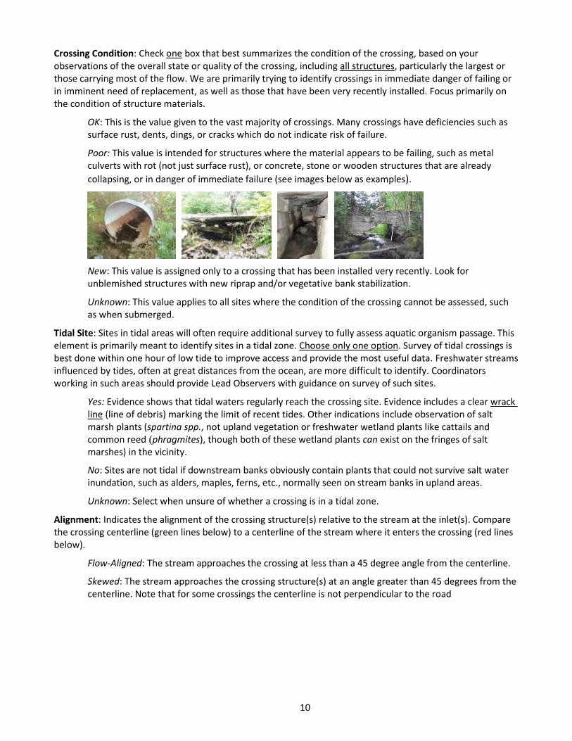
Crossing Condition: Check one box that best summarizes the condition of the crossing, based on your observations of the overall state or quality of the crossing, including all structures, particularly the largest or those carrying most of the flow. We are primarily trying to identify crossings in immediate danger of failing or in imminent need of replacement, as well as those that have been very recently installed. Focus primarily on the condition of structure materials.
OK: This is the value given to the vast majority of crossings. Many crossings have deficiencies such as surface rust, dents, dings, or cracks which do not indicate risk of failure.
Poor: This value is intended for structures where the material appears to be failing, such as metal culverts with rot (not just surface rust), or concrete, stone or wooden structures that are already
collapsing, or in danger of immediate failure (see images below as examples).
New: This value is assigned only to a crossing that has been installed very recently. Look for unblemished structures with new riprap and/or vegetative bank stabilization.
Unknown: This value applies to all sites where the condition of the crossing cannot be assessed, such as when submerged.
Tidal Site: Sites in tidal areas will often require additional survey to fully assess aquatic organism passage. This element is primarily meant to identify sites in a tidal zone. Choose only one option. Survey of tidal crossings is best done within one hour of low tide to improve access and provide the most useful data. Freshwater streams influenced by tides, often at great distances from the ocean, are more difficult to identify. Coordinators working in such areas should provide Lead Observers with guidance on survey of such sites.
Yes: Evidence shows that tidal waters regularly reach the crossing site. Evidence includes a clear wrack line (line of debris) marking the limit of recent tides. Other indications include observation of salt marsh plants (spartina spp., not upland vegetation or freshwater wetland plants like cattails and common reed (phragmites), though both of these wetland plants can exist on the fringes of salt marshes) in the vicinity.
No: Sites are not tidal if downstream banks obviously contain plants that could not survive salt water inundation, such as alders, maples, ferns, etc., normally seen on stream banks in upland areas.
Unknown: Select when unsure of whether a crossing is in a tidal zone.
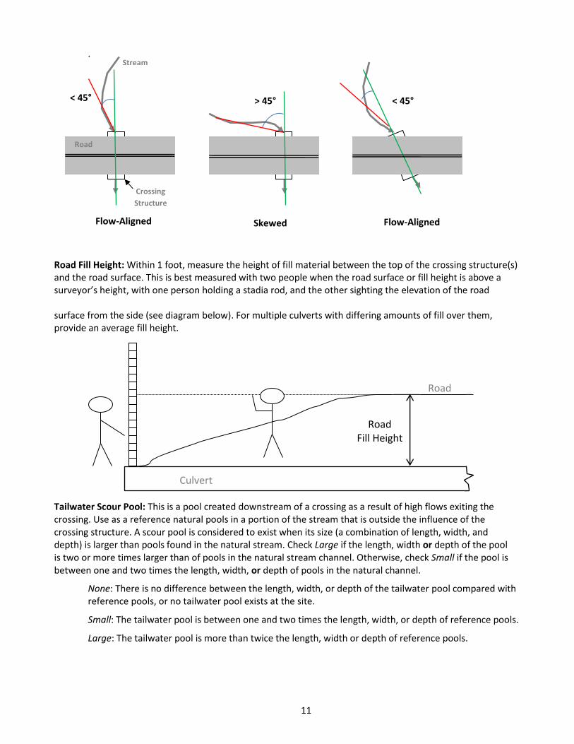
Alignment: Indicates the alignment of the crossing structure(s) relative to the stream at the inlet(s). Compare the crossing centerline (green lines below) to a centerline of the stream where it enters the crossing (red lines below).
Flow-Aligned: The stream approaches the crossing at less than a 45 degree angle from the centerline.
Skewed: The stream approaches the crossing structure(s) at an angle greater than 45 degrees from the centerline. Note that for some crossings the centerline is not perpendicular to the road
11
.
Road Fill Height: Within 1 foot, measure the height of fill material between the top of the crossing structure(s) and the road surface. This is best measured with two people when the road surface or fill height is above a surveyor’s height, with one person holding a stadia rod, and the other sighting the elevation of the road surface from the side (see diagram below). For multiple culverts with differing amounts of fill over them, provide an average fill height.
Tailwater Scour Pool: This is a pool created downstream of a crossing as a result of high flows exiting the crossing. Use as a reference natural pools in a portion of the stream that is outside the influence of the crossing structure. A scour pool is considered to exist when its size (a combination of length, width, and depth) is larger than pools found in the natural stream. Check Large if the length, width or depth of the pool is two or more times larger than of pools in the natural stream channel. Otherwise, check Small if the pool is between one and two times the length, width, or depth of pools in the natural channel.
None: There is no difference between the length, width, or depth of the tailwater pool compared with reference pools, or no tailwater pool exists at the site.
Small: The tailwater pool is between one and two times the length, width, or depth of reference pools.
Large: The tailwater pool is more than twice the length, width or depth of reference pools.
< 45°
Flow-Aligned
Road
Crossing
Structure
Stream
Skewed
> 45°
Flow-Aligned
< 45°
Road
Road Fill Height
Culvert
12
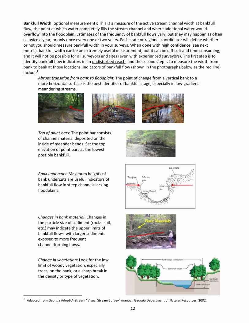
Bankfull Width (optional measurement): This is a measure of the active stream channel width at bankfull flow, the point at which water completely fills the stream channel and where additional water would overflow into the floodplain. Estimates of the frequency of bankfull flows vary, but they may happen as often as twice a year, or only once every one or two years. Each state or regional coordinator will define whether or not you should measure bankfull width in your surveys. When done with high confidence (see next metric), bankfull width can be an extremely useful measurement, but it can be difficult and time consuming, and it will not be possible for all surveyors and sites (even with experienced surveyors). The first step is to identify bankfull flow indicators in an undisturbed reach, and the second step is to measure the width from bank to bank at those locations. Indicators of bankfull flow (shown in the photographs below as the red line) include1:
Abrupt transition from bank to floodplain: The point of change from a vertical bank to a more horizontal surface is the best identifier of bankfull stage, especially in low‐gradient meandering streams.
Top of point bars: The point bar consists of channel material deposited on the inside of meander bends. Set the top elevation of point bars as the lowest possible bankfull.
Bank undercuts: Maximum heights of bank undercuts are useful indicators of bankfull flow in steep channels lacking floodplains.
Changes in bank material: Changes in the particle size of sediment (rocks, soil, etc.) may indicate the upper limits of bankfull flows, with larger sediments exposed to more frequent channel-forming flows.
Change in vegetation: Look for the low limit of woody vegetation, especially trees, on the bank, or a sharp break in the density or type of vegetation.
1 Adapted from Georgia Adopt-A-Stream “Visual Stream Survey” manual. Georgia Department of Natural Resources, 2002.
13
Bankfull Width Confidence: This qualifies your assessment of Bankfull Width based on your experience with its
measurement and whether sufficient criteria were met in your measurements. Choose only one option.
High: Select this option only when you are highly confident that your assessment of Bankfull Width meets the following criteria:
Clear indicators are present to define the limits of Bankfull Width.
The recorded value is an average of at least three measurements in different locations.
All measurements of Bankfull Width were taken in undisturbed locations well upstream or downstream of the crossing.
No tributaries enter between the crossing and your area(s) of measurements.
No measures taken at stream bends, pools, braided channels, or close to stream obstructions.
Low/Estimated: Select this when any of the above criteria cannot be met.
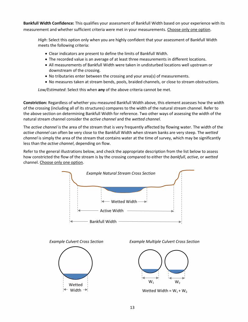
Constriction: Regardless of whether you measured Bankfull Width above, this element assesses how the width of the crossing (including all of its structures) compares to the width of the natural stream channel. Refer to the above section on determining Bankfull Width for reference. Two other ways of assessing the width of the natural stream channel consider the active channel and the wetted channel.
The active channel is the area of the stream that is very frequently affected by flowing water. The width of the active channel can often be very close to the Bankfull Width when stream banks are very steep. The wetted channel is simply the area of the stream that contains water at the time of survey, which may be significantly less than the active channel, depending on flow.
Refer to the general illustrations below, and check the appropriate description from the list below to assess how constricted the flow of the stream is by the crossing compared to either the bankfull, active, or wetted channel. Choose only one option.
Bankfull Width
Active Width
Wetted Width
Example Natural Stream Cross Section
Example Culvert Cross Section Example Multiple Culvert Cross Section
Wetted Width Wetted Width = W1 + W2
W1 W2
14
Severe: The total width of the crossing (sum of widths of all crossing structures) is less than 50% of the bankfull or active width of the natural stream, or the total wetted width of the crossing is less than 50% of the wetted width of the stream.
Moderate: The crossing is greater than 50% of the bankfull or active width of the natural stream, but less than the full bankfull or active channel width.
Spans Only Bankfull/Active Channel: The crossing encompasses the approximate width of the bankfull or active channel.
Spans Full Channel & Banks: The crossing completely spans beyond the Bankfull Width of the natural stream, as often evidenced by banks within the crossing structure.
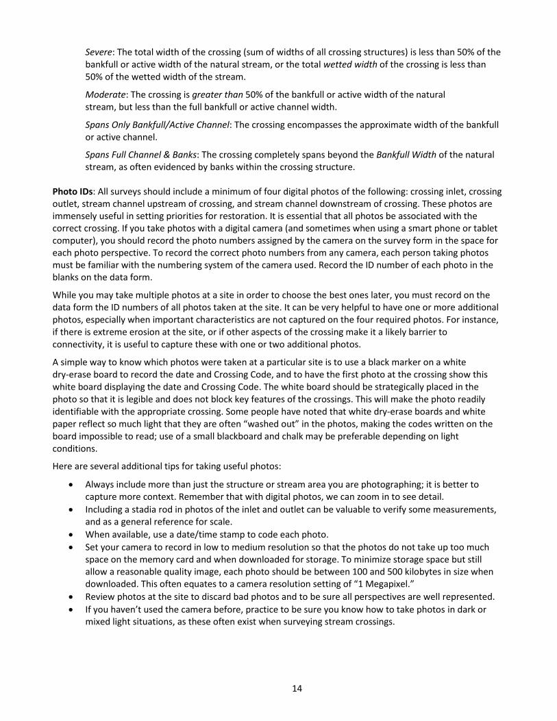
Photo IDs: All surveys should include a minimum of four digital photos of the following: crossing inlet, crossing outlet, stream channel upstream of crossing, and stream channel downstream of crossing. These photos are immensely useful in setting priorities for restoration. It is essential that all photos be associated with the correct crossing. If you take photos with a digital camera (and sometimes when using a smart phone or tablet computer), you should record the photo numbers assigned by the camera on the survey form in the space for each photo perspective. To record the correct photo numbers from any camera, each person taking photos must be familiar with the numbering system of the camera used. Record the ID number of each photo in the blanks on the data form.
While you may take multiple photos at a site in order to choose the best ones later, you must record on the data form the ID numbers of all photos taken at the site. It can be very helpful to have one or more additional photos, especially when important characteristics are not captured on the four required photos. For instance, if there is extreme erosion at the site, or if other aspects of the crossing make it a likely barrier to connectivity, it is useful to capture these with one or two additional photos.
A simple way to know which photos were taken at a particular site is to use a black marker on a white dry-erase board to record the date and Crossing Code, and to have the first photo at the crossing show this white board displaying the date and Crossing Code. The white board should be strategically placed in the photo so that it is legible and does not block key features of the crossings. This will make the photo readily identifiable with the appropriate crossing. Some people have noted that white dry‐erase boards and white paper reflect so much light that they are often “washed out” in the photos, making the codes written on the board impossible to read; use of a small blackboard and chalk may be preferable depending on light conditions.
Here are several additional tips for taking useful photos:
Always include more than just the structure or stream area you are photographing; it is better to capture more context. Remember that with digital photos, we can zoom in to see detail.
Including a stadia rod in photos of the inlet and outlet can be valuable to verify some measurements, and as a general reference for scale.
When available, use a date/time stamp to code each photo.
Set your camera to record in low to medium resolution so that the photos do not take up too much space on the memory card and when downloaded for storage. To minimize storage space but still allow a reasonable quality image, each photo should be between 100 and 500 kilobytes in size when downloaded. This often equates to a camera resolution setting of “1 Megapixel.”
Review photos at the site to discard bad photos and to be sure all perspectives are well represented.
If you haven’t used the camera before, practice to be sure you know how to take photos in dark or mixed light situations, as these often exist when surveying stream crossings.
15
The following are some examples of useful photos:
Site 1 Site2 Site 3
Inlet
Outlet
Upstream
Downstream
Crossing Comments: Use this area for brief comments about any aspect of the overall crossing survey that warrants additional information. Do not use this box for comments about particular structures; comment boxes for each structure are provided elsewhere on the form.
16
STRUCTURE DATA
Choose only one option for structure data fields except when identifying Internal Structures and Physical Barriers.
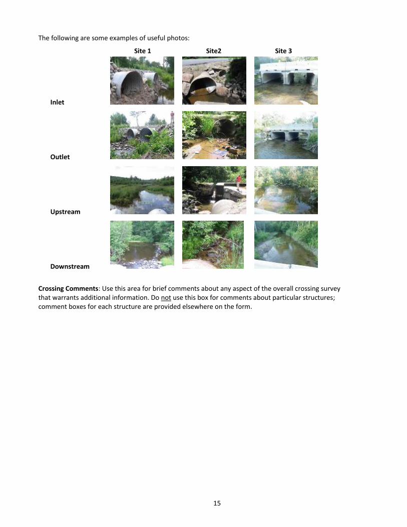
When there are multiple culverts and/or bridge cells, number them from left to right, while looking downstream toward the culvert inlet. The left-most structure is Structure 1, and structure numbers increase to the right. See examples below.
For each structure, you will complete the following information.
Structure Material: Record here the primary material of which the structure is made, i.e., the material that makes up the majority of the structure. When in doubt, focus on the material that is most in contact with the stream. If a structure is made of two materials, such as a bridge with concrete abutments and a steel deck structure, a metal culvert that has been lined along its entire bottom with concrete, or a crossing with different types of structures at inlet and outlet, select Combination. Choose only one option.
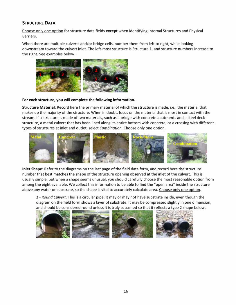
Inlet Shape: Refer to the diagrams on the last page of the field data form, and record here the structure number that best matches the shape of the structure opening observed at the inlet of the culvert. This is usually simple, but when a shape seems unusual, you should carefully choose the most reasonable option from among the eight available. We collect this information to be able to find the “open area” inside the structure above any water or substrate, so the shape is vital to accurately calculate area. Choose only one option.
1 - Round Culvert: This is a circular pipe. It may or may not have substrate inside, even though the diagram on the field form shows a layer of substrate. It may be compressed slightly in one dimension, and should be considered round unless it is truly squashed so that it reflects a type 2 shape below.
Metal Concrete Rock/Stone
Combination
Plastic
1 2 3 4
1 2
3 4 5
17
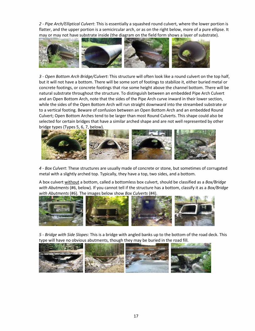
2 - Pipe Arch/Elliptical Culvert: This is essentially a squashed round culvert, where the lower portion is flatter, and the upper portion is a semicircular arch, or as on the right below, more of a pure ellipse. It may or may not have substrate inside (the diagram on the field form shows a layer of substrate).
3 - Open Bottom Arch Bridge/Culvert: This structure will often look like a round culvert on the top half, but it will not have a bottom. There will be some sort of footings to stabilize it, either buried metal or concrete footings, or concrete footings that rise some height above the channel bottom. There will be natural substrate throughout the structure. To distinguish between an embedded Pipe Arch Culvert and an Open Bottom Arch, note that the sides of the Pipe Arch curve inward in their lower section, while the sides of the Open Bottom Arch will run straight downward into the streambed substrate or to a vertical footing. Beware of confusion between an Open Bottom Arch and an embedded Round Culvert; Open Bottom Arches tend to be larger than most Round Culverts. This shape could also be selected for certain bridges that have a similar arched shape and are not well represented by other bridge types (Types 5, 6, 7, below).
4 - Box Culvert: These structures are usually made of concrete or stone, but sometimes of corrugated metal with a slightly arched top. Typically, they have a top, two sides, and a bottom.
A box culvert without a bottom, called a bottomless box culvert, should be classified as a Box/Bridge with Abutments (#6, below). If you cannot tell if the structure has a bottom, classify it as a Box/Bridge with Abutments (#6). The images below show Box Culverts (#4).
5 - Bridge with Side Slopes: This is a bridge with angled banks up to the bottom of the road deck. This type will have no obvious abutments, though they may be buried in the road fill.
18
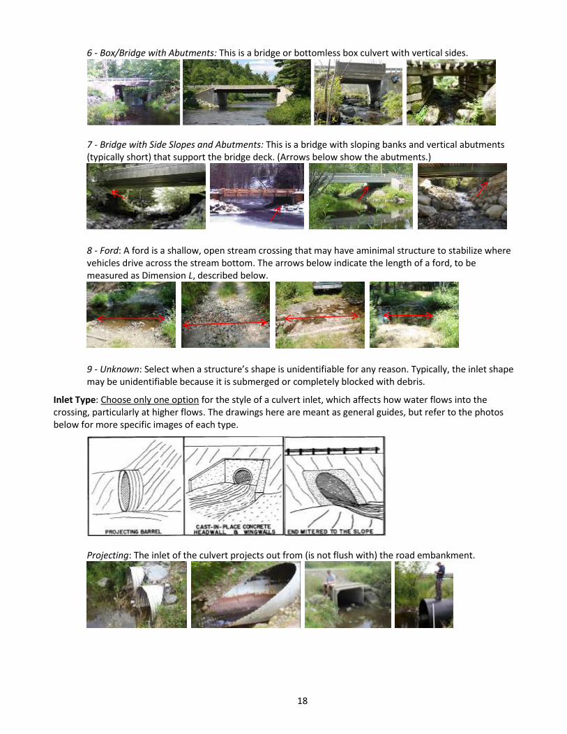
6 - Box/Bridge with Abutments: This is a bridge or bottomless box culvert with vertical sides.
7 - Bridge with Side Slopes and Abutments: This is a bridge with sloping banks and vertical abutments (typically short) that support the bridge deck. (Arrows below show the abutments.)
8 - Ford: A ford is a shallow, open stream crossing that may have aminimal structure to stabilize where vehicles drive across the stream bottom. The arrows below indicate the length of a ford, to be measured as Dimension L, described below.
9 - Unknown: Select when a structure’s shape is unidentifiable for any reason. Typically, the inlet shape may be unidentifiable because it is submerged or completely blocked with debris.
Inlet Type: Choose only one option for the style of a culvert inlet, which affects how water flows into the crossing, particularly at higher flows. The drawings here are meant as general guides, but refer to the photos below for more specific images of each type.
Projecting: The inlet of the culvert projects out from (is not flush with) the road embankment.
19
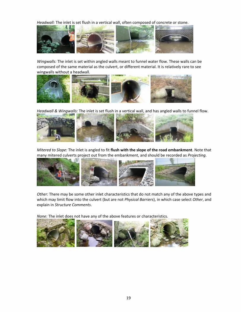
Headwall: The inlet is set flush in a vertical wall, often composed of concrete or stone.
Wingwalls: The inlet is set within angled walls meant to funnel water flow. These walls can be composed of the same material as the culvert, or different material. It is relatively rare to see wingwalls without a headwall.
Headwall & Wingwalls: The inlet is set flush in a vertical wall, and has angled walls to funnel flow.
Mitered to Slope: The inlet is angled to fit flush with the slope of the road embankment. Note that many mitered culverts project out from the embankment, and should be recorded as Projecting.
Other: There may be some other inlet characteristics that do not match any of the above types and which may limit flow into the culvert (but are not Physical Barriers), in which case select Other, and explain in Structure Comments.
None: The inlet does not have any of the above features or characteristics.
20
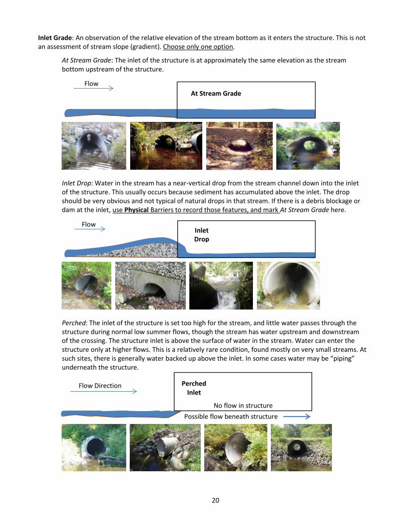
Inlet Grade: An observation of the relative elevation of the stream bottom as it enters the structure. This is not an assessment of stream slope (gradient). Choose only one option.
At Stream Grade: The inlet of the structure is at approximately the same elevation as the stream bottom upstream of the structure.
Inlet Drop: Water in the stream has a near-vertical drop from the stream channel down into the inlet of the structure. This usually occurs because sediment has accumulated above the inlet. The drop should be very obvious and not typical of natural drops in that stream. If there is a debris blockage or dam at the inlet, use Physical Barriers to record those features, and mark At Stream Grade here.
Perched: The inlet of the structure is set too high for the stream, and little water passes through the structure during normal low summer flows, though the stream has water upstream and downstream of the crossing. The structure inlet is above the surface of water in the stream. Water can enter the structure only at higher flows. This is a relatively rare condition, found mostly on very small streams. At such sites, there is generally water backed up above the inlet. In some cases water may be “piping” underneath the structure.
Flow Inlet Drop
Flow Direction Perched Inlet
No flow in structure
Possible flow beneath structure
Flow
At Stream Grade
21
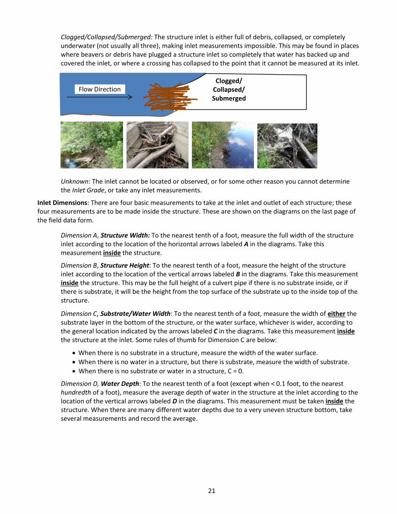
Clogged/Collapsed/Submerged: The structure inlet is either full of debris, collapsed, or completely underwater (not usually all three), making inlet measurements impossible. This may be found in places where beavers or debris have plugged a structure inlet so completely that water has backed up and covered the inlet, or where a crossing has collapsed to the point that it cannot be measured at its inlet.
Unknown: The inlet cannot be located or observed, or for some other reason you cannot determine the Inlet Grade, or take any inlet measurements.
Inlet Dimensions: There are four basic measurements to take at the inlet and outlet of each structure; these four measurements are to be made inside the structure. These are shown on the diagrams on the last page of the field data form.
Dimension A, Structure Width: To the nearest tenth of a foot, measure the full width of the structure inlet according to the location of the horizontal arrows labeled A in the diagrams. Take this measurement inside the structure.
Dimension B, Structure Height: To the nearest tenth of a foot, measure the height of the structure inlet according to the location of the vertical arrows labeled B in the diagrams. Take this measurement inside the structure. This may be the full height of a culvert pipe if there is no substrate inside, or if there is substrate, it will be the height from the top surface of the substrate up to the inside top of the structure.
Dimension C, Substrate/Water Width: To the nearest tenth of a foot, measure the width of either the substrate layer in the bottom of the structure, or the water surface, whichever is wider, according to the general location indicated by the arrows labeled C in the diagrams. Take this measurement inside the structure at the inlet. Some rules of thumb for Dimension C are below:
When there is no substrate in a structure, measure the width of the water surface.
When there is no water in a structure, but there is substrate, measure the width of substrate.
When there is no substrate or water in a structure, C = 0.
Dimension D, Water Depth: To the nearest tenth of a foot (except when < 0.1 foot, to the nearest hundredth of a foot), measure the average depth of water in the structure at the inlet according to the location of the vertical arrows labeled D in the diagrams. This measurement must be taken inside the structure. When there are many different water depths due to a very uneven structure bottom, take several measurements and record the average.
Flow Direction Clogged/
Collapsed/ Submerged
22
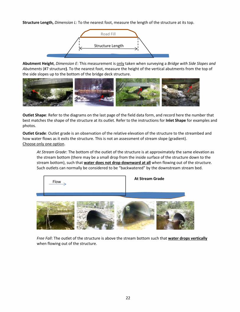
Structure Length, Dimension L: To the nearest foot, measure the length of the structure at its top.
Abutment Height, Dimension E: This measurement is only taken when surveying a Bridge with Side Slopes and Abutments (#7 structure). To the nearest foot, measure the height of the vertical abutments from the top of the side slopes up to the bottom of the bridge deck structure.
Outlet Shape: Refer to the diagrams on the last page of the field data form, and record here the number that best matches the shape of the structure at its outlet. Refer to the instructions for Inlet Shape for examples and photos.
Outlet Grade: Outlet grade is an observation of the relative elevation of the structure to the streambed and how water flows as it exits the structure. This is not an assessment of stream slope (gradient). Choose only one option.
At Stream Grade: The bottom of the outlet of the structure is at approximately the same elevation as the stream bottom (there may be a small drop from the inside surface of the structure down to the stream bottom), such that water does not drop downward at all when flowing out of the structure. Such outlets can normally be considered to be “backwatered” by the downstream stream bed.
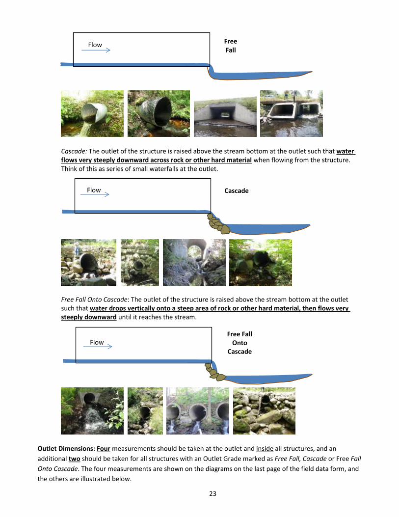
Free Fall: The outlet of the structure is above the stream bottom such that water drops vertically when flowing out of the structure.
Flow At Stream Grade
Road Fill
Structure Length
23
Free Fall
Flow
Cascade: The outlet of the structure is raised above the stream bottom at the outlet such that water flows very steeply downward across rock or other hard material when flowing from the structure. Think of this as series of small waterfalls at the outlet.
Free Fall Onto Cascade: The outlet of the structure is raised above the stream bottom at the outlet such that water drops vertically onto a steep area of rock or other hard material, then flows very steeply downward until it reaches the stream.
Outlet Dimensions: Four measurements should be taken at the outlet and inside all structures, and an
additional two should be taken for all structures with an Outlet Grade marked as Free Fall, Cascade or Free Fall
Onto Cascade. The four measurements are shown on the diagrams on the last page of the field data form, and
the others are illustrated below.
Free Fall Onto
Cascade
Flow
`
Cascade
Flow
24
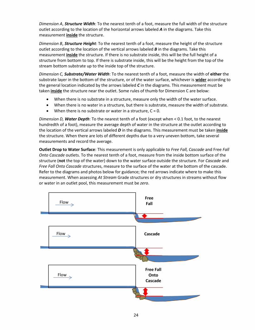
Dimension A, Structure Width: To the nearest tenth of a foot, measure the full width of the structure outlet according to the location of the horizontal arrows labeled A in the diagrams. Take this measurement inside the structure.
Dimension B, Structure Height: To the nearest tenth of a foot, measure the height of the structure outlet according to the location of the vertical arrows labeled B in the diagrams. Take this measurement inside the structure. If there is no substrate inside, this will be the full height of a structure from bottom to top. If there is substrate inside, this will be the height from the top of the stream bottom substrate up to the inside top of the structure.
Dimension C, Substrate/Water Width: To the nearest tenth of a foot, measure the width of either the substrate layer in the bottom of the structure, or of the water surface, whichever is wider according to the general location indicated by the arrows labeled C in the diagrams. This measurement must be taken inside the structure near the outlet. Some rules of thumb for Dimension C are below:
When there is no substrate in a structure, measure only the width of the water surface.
When there is no water in a structure, but there is substrate, measure the width of substrate.
When there is no substrate or water in a structure, C = 0.
Dimension D, Water Depth: To the nearest tenth of a foot (except when < 0.1 foot, to the nearest hundredth of a foot), measure the average depth of water in the structure at the outlet according to the location of the vertical arrows labeled D in the diagrams. This measurement must be taken inside the structure. When there are lots of different depths due to a very uneven bottom, take several measurements and record the average.
Outlet Drop to Water Surface: This measurement is only applicable to Free Fall, Cascade and Free Fall Onto Cascade outlets. To the nearest tenth of a foot, measure from the inside bottom surface of the structure (not the top of the water) down to the water surface outside the structure. For Cascade and Free Fall Onto Cascade structures, measure to the surface of the water at the bottom of the cascade. Refer to the diagrams and photos below for guidance; the red arrows indicate where to make this measurement. When assessing At Stream Grade structures or dry structures in streams without flow or water in an outlet pool, this measurement must be zero.
Free Fall Flow
Free Fall Onto
Cascade
Flow
`
Cascade
Flow

25
Outlet Drop to Stream Bottom: To the nearest tenth of a foot, measure from the inside bottom surface of the structure (not the top of the water) down to the stream bottom at the place where the water falls from the outlet. For At Stream Grade structures, this may be hard to measure, and may be a very small drop. For Cascade and Free Fall Onto Cascade structures, measure the full vertical drop to the stream bottom at the end of the cascade. Refer to the diagrams below for guidance.
Free Fall Free Fall Onto Cascade
Free Fall Flow
Free Fall Onto
Cascade Flow
`
Flow At Stream Grade
Cascade
`
Flow
Free Fall
Outlet Drop into Pool
26
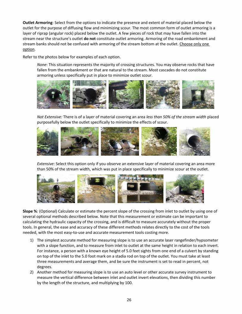
Outlet Armoring: Select from the options to indicate the presence and extent of material placed below the outlet for the purpose of diffusing flow and minimizing scour. The most common form of outlet armoring is a layer of riprap (angular rock) placed below the outlet. A few pieces of rock that may have fallen into the stream near the structure’s outlet do not constitute outlet armoring. Armoring of the road embankment and stream banks should not be confused with armoring of the stream bottom at the outlet. Choose only one option.
Refer to the photos below for examples of each option.
None: This situation represents the majority of crossing structures. You may observe rocks that have fallen from the embankment or that are natural to the stream. Most cascades do not constitute armoring unless specifically put in place to minimize outlet scour.
Not Extensive: There is of a layer of material covering an area less than 50% of the stream width placed purposefully below the outlet specifically to minimize the effects of scour.
Extensive: Select this option only if you observe an extensive layer of material covering an area more than 50% of the stream width, which was put in place specifically to minimize scour at the outlet.
Slope %: (Optional) Calculate or estimate the percent slope of the crossing from inlet to outlet by using one of several optional methods described below. Note that this measurement or estimate can be important to calculating the hydraulic capacity of the crossing, and is difficult to measure accurately without the proper tools. In general, the ease and accuracy of these different methods relates directly to the cost of the tools needed, with the most easy-to-use and accurate measurement tools costing more.
1) The simplest accurate method for measuring slope is to use an accurate laser rangefinder/hypsometer with a slope function, and to measure from inlet to outlet at the same height in relation to each invert. For instance, a person with a known eye height of 5.0 feet sights from one end of a culvert by standing on top of the inlet to the 5.0 foot mark on a stadia rod on top of the outlet. You must take at least three measurements and average them, and be sure the instrument is set to read in percent, not degrees.
2) Another method for measuring slope is to use an auto level or other accurate survey instrument to measure the vertical difference between inlet and outlet invert elevations, then dividing this number by the length of the structure, and multiplying by 100.
27
3) The next best approach is to use a clinometer that measures slope to the nearest half percent, measuring from a fixed point above one invert (inlet or outlet) to the same height above the opposite invert such as described above under method 1. Many clinometers include both percent and degree scales; be sure to use the percent scale.
4) Another less accurate approach is to sight from a fixed elevation above the inlet invert with a hand level to a stadia rod at the outlet invert, to take the difference in height between the two points, divide by the structure length, and multiply by 100.
Slope % Confidence: Rate the confidence you have in your slope measurement or estimate according to the criteria below:
High: Used method 1 above, taking multiple measurements and averaging them, or used method 2 above.
Low: Used methods 3 or 4 above, taking multiple measurements and averaging them.
Structure Substrate Matches Stream: Choose only one option based on a comparison of the substrate (e.g., rock, gravel, sand) inside the structure and the substrate in the natural, undisturbed stream channel.
None: Select this option when there is very little (e.g., a thin layer of silt or a few pieces of rock) or no substrate inside the structure.
Comparable: The substrate inside the structure is similar in size to the substrate in the natural stream channel.
Contrasting: The substrate inside the structure is different in size from the substrate in the natural channel.
Not Appropriate: The substrate inside the structure is very different in size (usually much larger) than the substrate in the natural stream channel. Imagine turtles that typically move along a sandy stream trying to traverse an area of large cobbles, angular riprap or boulders (rarely observed).
Unknown: There is no way to observe if there is substrate inside the structure or what type it is. Select this option when deep, fast, or dark water or other factors do not allow direct observation.
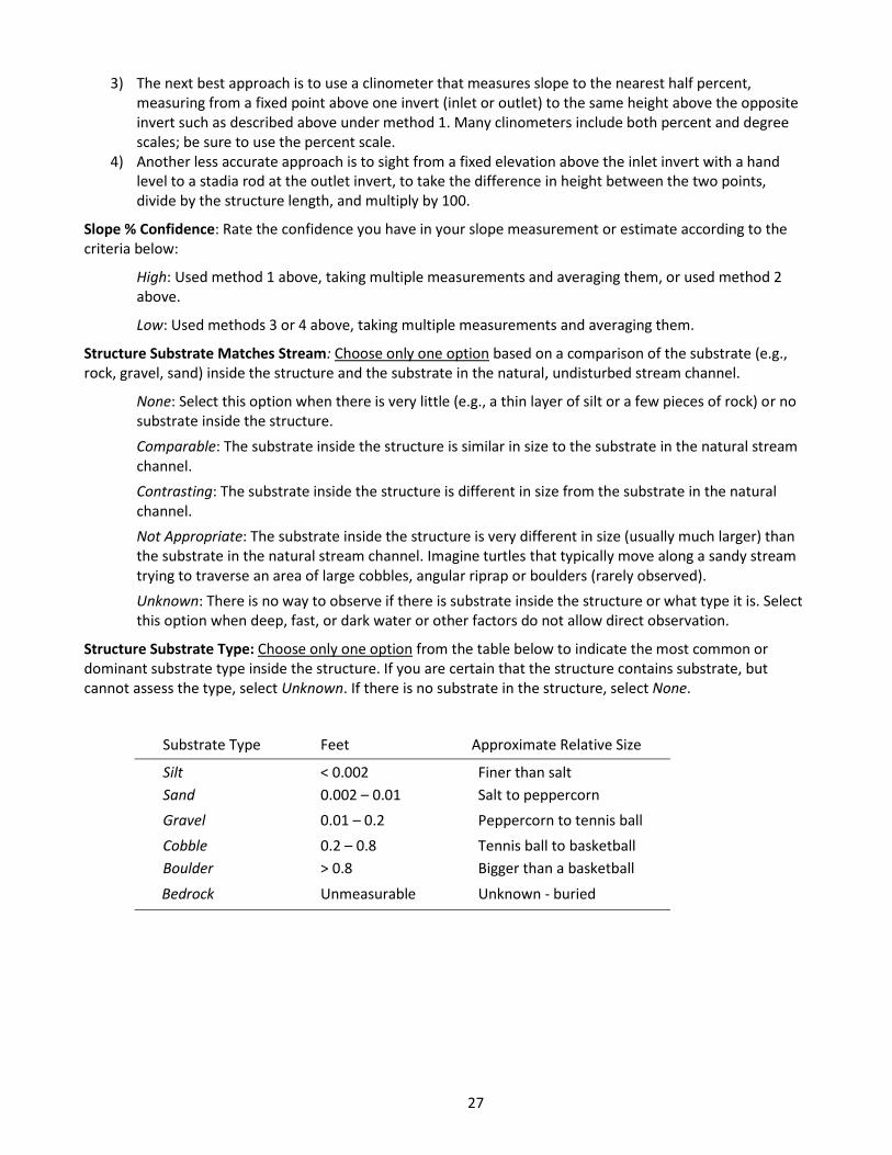
Structure Substrate Type: Choose only one option from the table below to indicate the most common or dominant substrate type inside the structure. If you are certain that the structure contains substrate, but cannot assess the type, select Unknown. If there is no substrate in the structure, select None.
Substrate Type Feet Approximate Relative Size
Silt < 0.002 Finer than salt
Sand 0.002 – 0.01 Salt to peppercorn
Gravel 0.01 – 0.2 Peppercorn to tennis ball
Cobble 0.2 – 0.8 Tennis ball to basketball
Boulder > 0.8 Bigger than a basketball
Bedrock Unmeasurable Unknown - buried
28
Structure Substrate Coverage: Choose one option, based on the extent of the substrate inside the crossing structure as a continuous layer across the entire bottom of the structure from bank to bank (side to side).
None: Substrate covers less than 25% of the length of the structure, or there is no substrate inside the structure at all.
25%: Substrate covers at least 25% of the length of the structure.
50%: Substrate covers at least 50% of the length of the structure.
75%: Substrate covers at least 75% of the length of the structure.
100%: Substrate forms a continuous layer throughout the entire structure.
Unknown: It is not possible to directly observe whether substrate forms a continuous layer on the structure bottom.
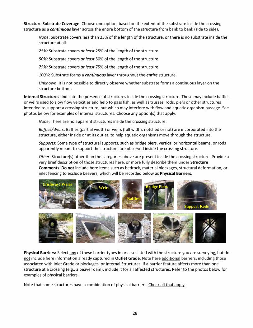
Internal Structures: Indicate the presence of structures inside the crossing structure. These may include baffles or weirs used to slow flow velocities and help to pass fish, as well as trusses, rods, piers or other structures intended to support a crossing structure, but which may interfere with flow and aquatic organism passage. See photos below for examples of internal structures. Choose any option(s) that apply.
None: There are no apparent structures inside the crossing structure.
Baffles/Weirs: Baffles (partial width) or weirs (full width, notched or not) are incorporated into the structure, either inside or at its outlet, to help aquatic organisms move through the structure.
Supports: Some type of structural supports, such as bridge piers, vertical or horizontal beams, or rods apparently meant to support the structure, are observed inside the crossing structure.
Other: Structure(s) other than the categories above are present inside the crossing structure. Provide a very brief description of those structures here, or more fully describe them under Structure Comments. Do not include here items such as bedrock, material blockages, structural deformation, or inlet fencing to exclude beavers, which will be recorded below as Physical Barriers.
Physical Barriers: Select any of these barrier types in or associated with the structure you are surveying, but do not include here information already captured in Outlet Grade. Note here additional barriers, including those associated with Inlet Grade or blockages, or Internal Structures. If a barrier feature affects more than one structure at a crossing (e.g., a beaver dam), include it for all affected structures. Refer to the photos below for examples of physical barriers.
Note that some structures have a combination of physical barriers. Check all that apply.
Weirs
Baffles
Bridge Piers
Support Rods
(Fishway) Weirs
29
None: There are no physical barriers associated with this structure aside from any already noted in Outlet Grade.
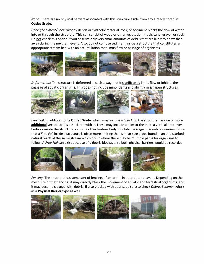
Debris/Sediment/Rock: Woody debris or synthetic material, rock, or sediment blocks the flow of water into or through the structure. This can consist of wood or other vegetation, trash, sand, gravel, or rock. Do not check this option if you observe only very small amounts of debris that are likely to be washed away during the next rain event. Also, do not confuse sediment inside a structure that constitutes an appropriate stream bed with an accumulation that limits flow or passage of organisms.
Deformation: The structure is deformed in such a way that it significantly limits flow or inhibits the passage of aquatic organisms. This does not include minor dents and slightly misshapen structures.
Free Fall: In addition to its Outlet Grade, which may include a Free Fall, the structure has one or more additional vertical drops associated with it. These may include a dam at the inlet, a vertical drop over bedrock inside the structure, or some other feature likely to inhibit passage of aquatic organisms. Note that a Free Fall inside a structure is often more limiting than similar size drops found in an undisturbed natural reach of the same stream which occur where there may be multiple paths for organisms to follow. A Free Fall can exist because of a debris blockage, so both physical barriers would be recorded.
Fencing: The structure has some sort of fencing, often at the inlet to deter beavers. Depending on the mesh size of that fencing, it may directly block the movement of aquatic and terrestrial organisms, and it may become clogged with debris. If also blocked with debris, be sure to check Debris/Sediment/Rock as a Physical Barrier type as well.
30
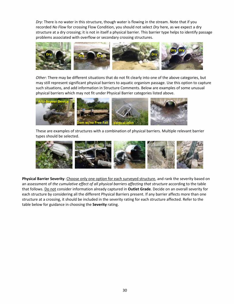
Dry: There is no water in this structure, though water is flowing in the stream. Note that if you recorded No Flow for crossing Flow Condition, you should not select Dry here, as we expect a dry structure at a dry crossing; it is not in itself a physical barrier. This barrier type helps to identify passage problems associated with overflow or secondary crossing structures.
Other: There may be different situations that do not fit clearly into one of the above categories, but may still represent significant physical barriers to aquatic organism passage. Use this option to capture such situations, and add information in Structure Comments. Below are examples of some unusual physical barriers which may not fit under Physical Barrier categories listed above.
These are examples of structures with a combination of physical barriers. Multiple relevant barrier types should be selected.
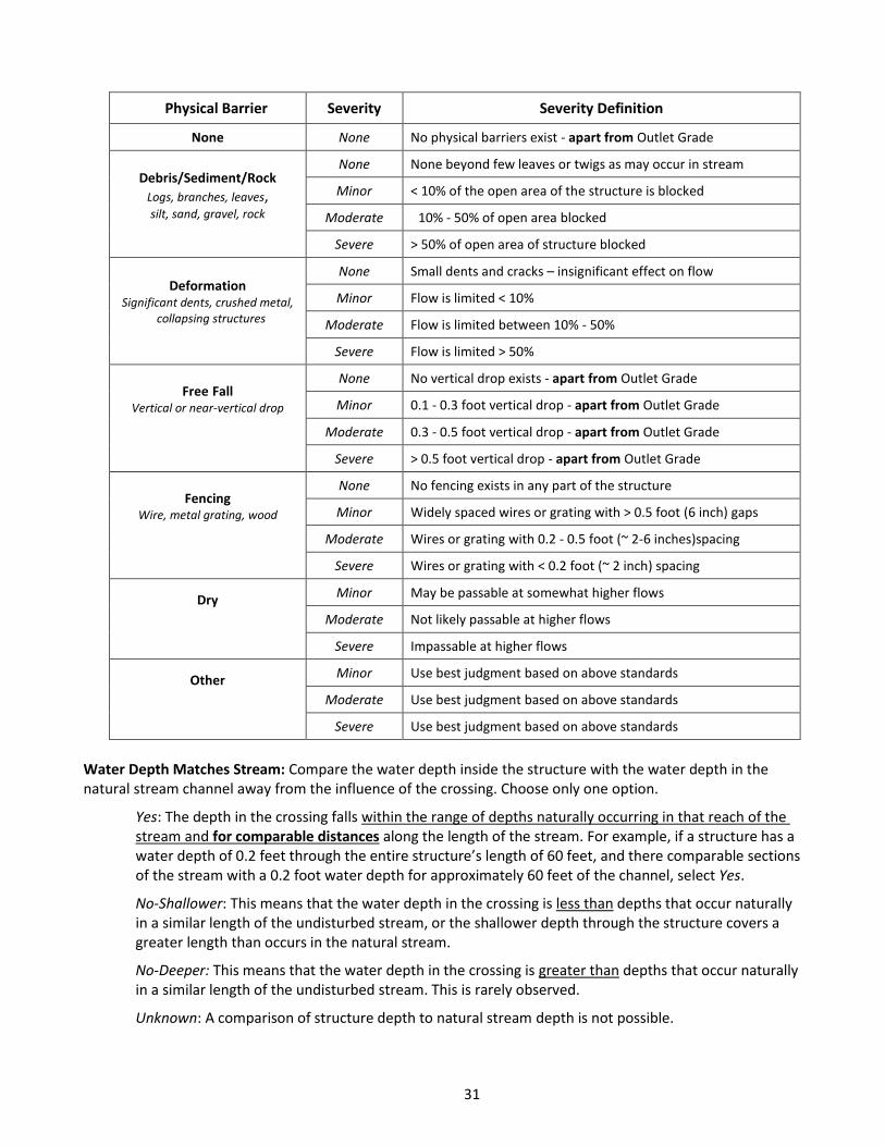
Physical Barrier Severity: Choose only one option for each surveyed structure, and rank the severity based on an assessment of the cumulative effect of all physical barriers affecting that structure according to the table that follows. Do not consider information already captured in Outlet Grade. Decide on an overall severity for each structure by considering all the different Physical Barriers present. If any barrier affects more than one structure at a crossing, it should be included in the severity rating for each structure affected. Refer to the table below for guidance in choosing the Severity rating.
Anti-Beaver Device
Dam w/no Free Fall Vertical Inlet
Dry Dry Dry Dry Dry
Dry
31
Physical Barrier Severity Severity Definition
None None No physical barriers exist - apart from Outlet Grade
Debris/Sediment/Rock
Logs, branches, leaves, silt, sand, gravel, rock
None None beyond few leaves or twigs as may occur in stream
Minor < 10% of the open area of the structure is blocked
Moderate 10% - 50% of open area blocked
Severe > 50% of open area of structure blocked
Deformation Significant dents, crushed metal,
collapsing structures
None Small dents and cracks – insignificant effect on flow
Minor Flow is limited < 10%
Moderate Flow is limited between 10% - 50%
Severe Flow is limited > 50%
Free Fall Vertical or near-vertical drop
None No vertical drop exists - apart from Outlet Grade
Minor 0.1 - 0.3 foot vertical drop - apart from Outlet Grade
Moderate 0.3 - 0.5 foot vertical drop - apart from Outlet Grade
Severe > 0.5 foot vertical drop - apart from Outlet Grade
Fencing Wire, metal grating, wood
None No fencing exists in any part of the structure
Minor Widely spaced wires or grating with > 0.5 foot (6 inch) gaps
Moderate Wires or grating with 0.2 - 0.5 foot (~ 2-6 inches)spacing
Severe Wires or grating with < 0.2 foot (~ 2 inch) spacing
Dry
Minor May be passable at somewhat higher flows
Moderate Not likely passable at higher flows
Severe Impassable at higher flows
Other
Minor Use best judgment based on above standards
Moderate Use best judgment based on above standards
Severe Use best judgment based on above standards
Water Depth Matches Stream: Compare the water depth inside the structure with the water depth in the natural stream channel away from the influence of the crossing. Choose only one option.
Yes: The depth in the crossing falls within the range of depths naturally occurring in that reach of the stream and for comparable distances along the length of the stream. For example, if a structure has a water depth of 0.2 feet through the entire structure’s length of 60 feet, and there comparable sections of the stream with a 0.2 foot water depth for approximately 60 feet of the channel, select Yes.
No-Shallower: This means that the water depth in the crossing is less than depths that occur naturally in a similar length of the undisturbed stream, or the shallower depth through the structure covers a greater length than occurs in the natural stream.
No-Deeper: This means that the water depth in the crossing is greater than depths that occur naturally in a similar length of the undisturbed stream. This is rarely observed.
Unknown: A comparison of structure depth to natural stream depth is not possible.
32
Water Velocity Matches Stream: Compare the water velocity inside the structure with the velocity in the natural stream channel away from the influence of the crossing. Choose only one option.
Yes: The water velocity in the crossing falls within the range of velocities naturally occurring in that reach of the stream for comparable distances. If velocities in the crossing are observed in the natural stream channel, and those velocities persist over the same distance as the structure length, select Yes.
No-Faster: This means that the water velocity in the structure is greater than velocities that occur naturally in a similar length of the undisturbed stream, or the velocity through the structure persists over a longer distance than occurs in the natural stream.
No-Slower: This means that the velocity in the crossing is less than velocities that occur naturally in a similar length of the undisturbed stream. This is rarely observed.
Unknown: A comparison of structure velocity to natural stream velocity is not possible.
Dry Passage Through Structure? Consider this question two different ways, depending on whether water is flowing through the structure. Choose only one option.
If there is water flowing in the structure: Is there a continuous dry stream bank through at least one side of the structure that allows the safe movement of terrestrial or semi-aquatic animals, and does this dry pathway connect to the stream banks upstream and downstream of the structure?
If there is no water flowing in the structure: then there is continuous dry passage through the structure.
Yes: A continuous bank connects upstream, through the structure, and downstream, or there is otherwise continuous dry passage through the structure.
No: There is no dry passage, the dry passage is not continuous, or the dry passage through the structure does not connect with stream banks upstream or downstream.
Unknown: It is not possible to determine if continuous dry passage exists through this structure.
Height Above Dry Passage: If there is dry passage through the structure, measure the average height from the dry stream bank to the top of the structure directly above (i.e., the clearance) to the nearest tenth of a foot. If both stream banks are dry and connected, record the higher measurement. If the structure has no water flow, measure the average height above the bottom of the structure or dry stream bed to the top of the structure.
Structure Comments: Use this area to briefly comment on any aspects of the structure needing more information. Enter comments about the overall crossing in the Crossing Comments box.