n91-24609 - nasa · the data relay tracking satellite (drts) ... it isa result of the temperature...
TRANSCRIPT

N91-24609
AN ANTENNA-POINTING MECHANISM FOR THE
ETS-VI K-BAND SINGLE ACCESS (KSA) ANTENNA
Noboru TAKADA*
Takahiro AMANO**, Toshiro OHHASHI** and Shigeo WACHI**
Abstract
This paper describes both the design philosophy for the Antenna Pointing
Mechanism (APM) to be used for the K-band Single Access (KSA) antenna system and
experimental results of the APM's Engineering Model (EM) tests. The KSA antenna
system will be flown on the Engineering Test Satellite VI (ETS-Vl).
I. Introduction
Recently, the requirements of data-relay satellite systems have been increasing.
The Data Relay Tracking Satellite (DRTS) and some user satellites will be launched in
the 1990s in Japan. The DRTS system will provide data-relay services between low-
earth-orbit satellites and ground stations. A high bit-rate communications link is
required to transmit the enormous amount of data (including image data), so pointing
requirements for an antenna are becoming more stringent. The technology of acquiring
and tracking low-earth-orbit satellites is also becoming more important. The KSA
antenna system of ETS-Vl is currently under development to establish the essential
technology of DRTS for acquiring and tracking satellites. The mechanism to position
the antenna in a desired direction forms one of the essential components of this
technology. The engineering model of the APM for the ETS-Vl KSA antenna has been
designed, developed, integrated and tested.
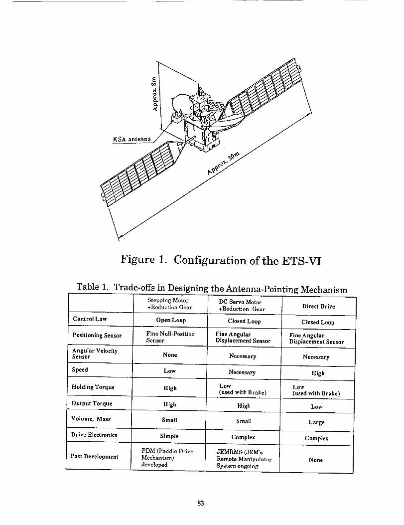
The configuration of ETS-VI is shown in Figure 1. The KSA antenna is attached
to the earth panel of the main body. The APM of the KSA positions the antenna about 2
axes to acquire the user satellite and the ground terminal, while providing the antenna
position signal and physical support for the antenna.
The results of design trade-offs are shown in Table 1. For the APM, speed can
be controlled by pulse rates; the antenna position can be determined by counting input
pulses without the need for a fine angular displacement sensor; the antenna position
can be held by the holding torque of a stepping motor without the need for a brake; and
Tsukuba Space Center, National Space Development Agency of Japan, 2-1-1, Sengen Tsukuba-shi,Ibaraki, 305 JapanToshiba Corporation, Komukai Works, 1, Toshiba-cho, Komukai, Saiwai-ku, Kawasaki-shi,Kanagawa, 210 Japan
77
https://ntrs.nasa.gov/search.jsp?R=19910015295 2018-07-29T00:09:27+00:00Z

the driving electronic circuit can be simple. So an APM using a stepping motor, aharmonic drive, and a position indicator was selected.
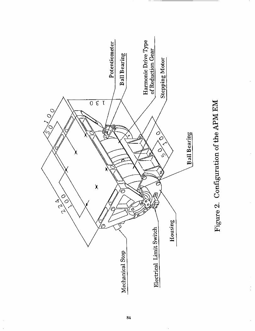
The APM consists of a two-axis gimbal. Only one axis of the Engineering Modelof the APM (APM-EM) was planned to be manufactured to evaluate functionality. Themechanical configuration of the APM EM is shown in Figure 2.
The APM EM consists of
• A stepping motor, whose function is to rotate the antenna according to inputpulses.
• A harmonic drive, whose function is to reduce the rotation angle and toincrease the rotation torque of the stepping motor.
• A position indicator, whose function is to provide a position signal for theantenna.
• Bearings, which support the structure assembly.• An electrical limit switch, whose function is to provide a stop signal in the case
of exceeding the permitted limit for the rotation.• Mechanical stoppers, whose function is to stop the rotation.• A structure assembly, which supports the antenna and the above elements.
2. System Requirements for the APM
The system requirements for the APM are shown in Table 2. The maximum slewrate is the one required to acquire the low-orbit user satellite. The pointing range isdetermined by the need to cover the orbit of the user satellites. The step size is drivenby the range of the Radio Frequency (RF) sensor and by other factors. The holdingtorque is necessary to prevent rotation of the KSA antenna at the time of thedeployment and the firing of thrusters for the main body during attitude or orbit control.Maximum mass and electric power are also determined as a part of identifying systemrequirements.
3. Design of the APM
3.1 Design philosophy
The system requirements for a small step size is one of the most importantspecifications allowing the APM to achieve high pointing accuracy. To accomplish highpointing accuracy, the need to prevent alignment errors becomes very strict. Twosources of alignment errors are mentioned. One is static error and the other is dynamicerror. The static error is almost negligible in rotating the APM about 2 axes. However,dynamic errors cannot be neglected. So the dynamic errors are considered in thedesign.
78
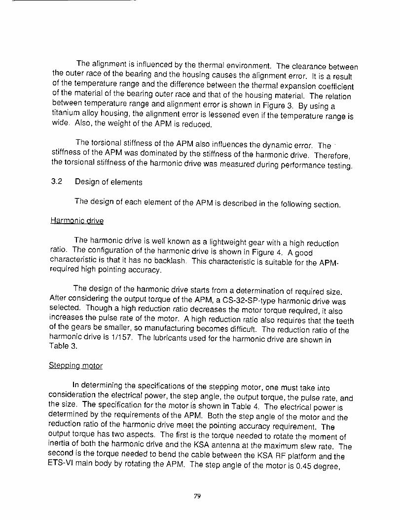
The alignment is influenced by the thermal environment. The clearance betweenthe outer race of the bearing and the housing causes the alignment error. It is a resultof the temperature range and the difference between the thermal expansion coefficientof the material of the bearing outer race and that of the housing material. The relationbetween temperature range and alignment error is shown in Figure 3. By using atitanium alloy housing, the alignment error is lessened even if the temperature range iswide. Also, the weight of the APM is reduced.
The torsional stiffness of the APM also influences the dynamic error. Thestiffness of the APM was dominated by the stiffness of the harmonic drive. Therefore,the torsional stiffness of the harmonic drive was measured during performance testing.
3.2 Design of elements
The design of each element of the APM is described in the following section.
H#rmoniG _rive
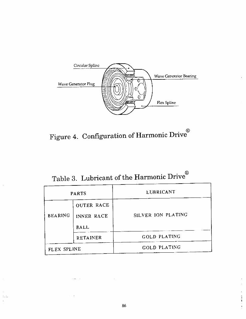
The harmonic drive is well known as a lightweight gear with a high reduction
ratio. The configuration of the harmonic drive is shown in Figure 4. A good
characteristic is that it has no backlash. This characteristic is suitable for the APM-
required high pointing accuracy.
The design of the harmonic drive starts from a determination of required size.
After considering the output torque of the APM, a CS-32-SP-type harmonic drive was
selected. Though a high reduction ratio decreases the motor torque required, it also
increases the pulse rate of the motor. A high reduction ratio also requires that the teeth
of the gears be smaller, so manufacturing becomes difficult. The reduction ratio of theharmonic drive is 1/I 57. The lubricants used for the harmonic drive are shown in
Table 3.
Steppingmotor
In determining the specifications of the stepping motor, one must take into
consideration the electrical power, the step angle, the output torque, the pulse rate, and
the size. The specification for the motor is shown in Table 4. The electrical power is
determined by the requirements of the APM. Both the step angle of the motor and the
reduction ratio of the harmonic drive meet the pointing accuracy requirement. The
output torque has two aspects. The first is the torque needed to rotate the moment ofinertia of both the harmonic drive and the KSA antenna at the maximum slew rate. The
second is the torque needed to bend the cable between the KSA RF platform and the
ETS-VI main body by rotating the APM. The step angle of the motor is 0.45 degree,
79

and the motor can respond to a pulse rate of 110 pulses per second (pps) to performthe maximum slew rate of the APM. Generally, the torque of a stepping motor isproportional both to the square of the diameter and to the axial length. Therefore, theweight of the motor is mainly determined by the output torque. The diameter of themotor is equal to that of the harmonic drive.
Position inolicator
During signal acquisition, the KSA antenna direction is positioned by closed-loop
control using the output of the position indicator. So the position indicator is required to
provide the correct position of the antenna. The potentiometer was chosen because of
its heritage in space, simplicity of the electric circuit, and light weight. The specifications
of the potentiometer are shown in Table 5.
Bearings
Radial and axial load capacity are the most important requirements for the
bearings. Light weight and protection from the harmonic drive's wear debris are also
required for the bearings. Therefore, the shielding-type, single deep-groove ball
bearings (6008ZZZ) were selected. The solid lubricant and the material of a retainer for
the bearings are described in Table 6.
4. Results of design
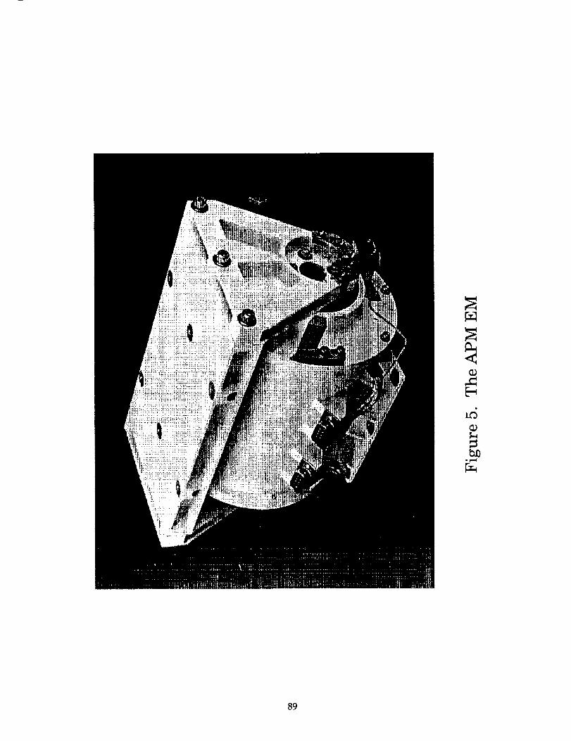
The results of the design are shown in Table 7. The APM EM satisfies every
requirement. The developed APM EM is shown in Figure 5.
5. Test of the APM
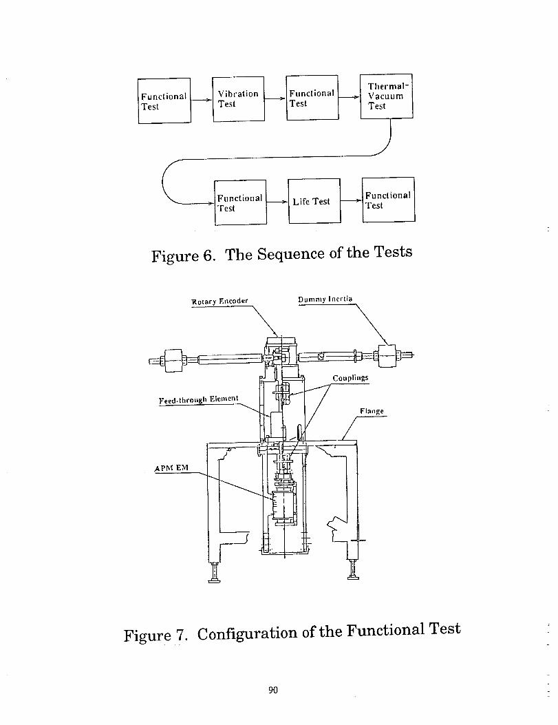
5.1 Sequence of the test
The APM EM was subjected to a functional test, a thermal-vacuum test and a
vibration test. After these tests, the requirement of a 3-year orbital life was shown to be
met by performing the life test in a thermal-vacuum environment. The sequence of
these tests is shown in Figure 6.
5.2 Method of test
The test configuration for the functional test is shown in Figure 7. A dummy
inertial mass simulating the moment of inertia of the KSA antenna and RF compartment
was connected to the APM through couplings and a vacuum feed-through element. The
dummy inertial mass, consisting of four masses, was rotated in a horizontal plane so
imbalance of the masses gave no torque to the APM. Therefore, this configuration was
80
.................................... r
suitable for measuring a small step angle with heavy inertia. An accurate rotary
encoder was set at the top of the functional-test apparatus. The small step size of the
APM was measured by the rotary encoder. The environment around the APM was
gaseous nitrogen at the time of operation.
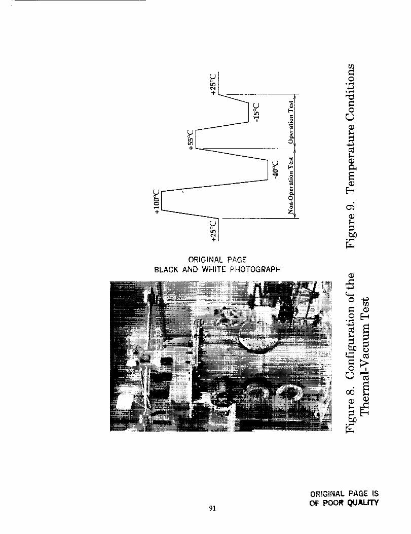
For the thermal-vacuum test, the functional-test apparatus was used again. The
APM and the hardware below the flange were in a vacuum chamber. The configuration
for the thermal-vacuum test is shown in Figure 8. The temperature of the APM was
controlled by the base plate temperature. The vacuum level was less than 10 -5 tom
The life-test configuration was the same as the one for the thermal-vacuum test, except
that the torque for the APM to bend the cable between the KSA RF platform and the
ETS-VI main body is simulated.
For the functional test and the thermal-vacuum test, the following functions and
performance parameters of the APM were measured:
• electric power• maximum slew rate
• step size
• holding torque
The temperature conditions of the thermal-vacuum test are shown in Figure 9.
The functions and the performances of the APM were measured at -15°C and +55°C in
the thermal-vacuum test. The vibration test was performed to confirm that the APMwould survive the launch environment.
To demonstrate the capability of a 3-year orbital life, the life test was performedin the thermal-vacuum environment for about 5 months. For the life test, the APM
rotated the dummy inertial mass against the torque required to bend the RF cables for
over a +10-degree range. The driving pattern was determined for the assumed case ofa user satellite for 3 years. Functions and performance were measured about every2 weeks.
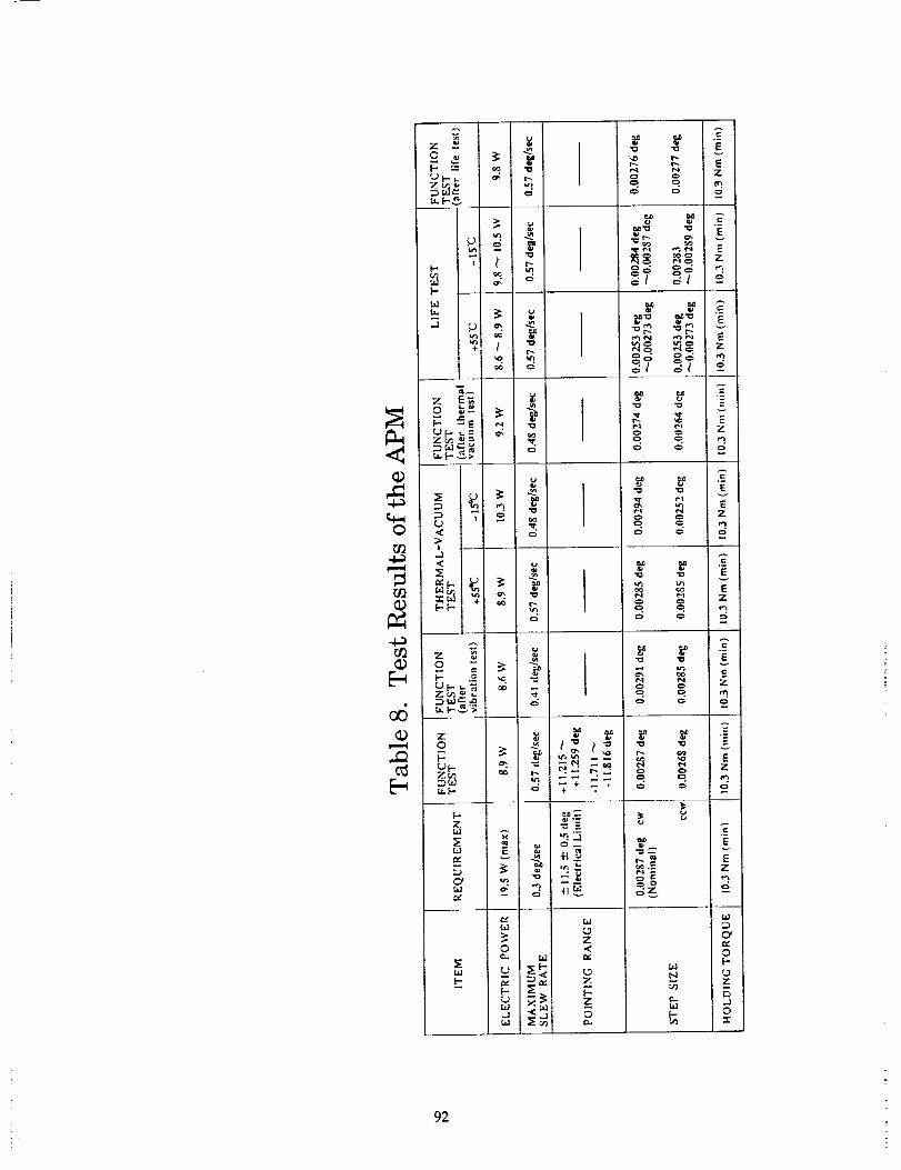
6. Test results
Performance data from the functional test, thermal-vacuum test and the life test
are shown in Table 8. The APM EM accomplished the required functions and
performance both at atmospheric pressure and in thermal-vacuum conditions. Its
performance did degrade after the vibration test. Also, after the life test, the APM
satisfied all of its requirements.
81
7. Conclusion
The design of the APM for the KSA antenna of ETS-Vl satellite was completed,
and capability of the design to meet all performance requirements was established by
test.
82
KSA antenna
Figure 1. Configuration of the ETS-VI
Table 1. Trade-offs in Designing the Antenna-Pointing Mechanism
Stepping Motor DC Serve MotorDirect Drive
+Reduction Gear +Reduction Gear
Control Law Open Loop Closed Loop Closed Loop
Positioning Sensor Fine Null-Position Fine Angular Fine AngularSensor Displacement Sensor Displacement Sensor
Angular Velocity None Necessary NecessarySensor
Speed Low Necessary High
Low LowHolding Torque High (used with Brake) (used with Brake)
Output Torque High High Low
Volume, Mass Small Small Large
Drive Electronics Simple Complex Complex
PDM (Paddle Drive JEMRMS (JEM's
Past Development Mechanism) Remote Manipulator None
developed System ongoing
83
/
/!
\\
xA0
O• r,,,I
0
0_,,I
84

Table 2. Requirements for the APM
ITEM REQUIREMENT
MASS i0 kg (max)
ELECTRIC POWER 39 W (max)SLEWING MODE4.5 W (max) TRACKING MODE
POINTING RANGE 0.3 deg/sec
MAXIMUM SLEW RATE +-10 deg
STEP SIZE 0.005 deg (max)
HOLDING TORQUE 10.3Nm (min)
PAYLOAD INERTIA 13 kgm2 (max)
REQUIRED LIFE 3 YEARS
o. os
0.04
f_
0.03
0.02
O.Ol
Housing Material
u I , | i
lO 30 50 lO
TEMPERATURE RANGE (°C)
Figure 3. Temperature Range and Alignment Error
85
CircularSpline
WaveGeneratorPlugWaveGeneratorBearing
FlexSpline
Figure 4. Configuration of Harmonic Drive _
Table 3. Lubricant of the Harmonic DrivJ _
BEARING
PARTS
OUTER RACE
INNER RACE
BALL
LUBRICANT
SILVER ION PLATING
RETAINER GOLD PLATING
FLEX SPL1NE GOLD PLATING
86

Table 4. Specifications of the Stepping Motor
ITEM
ELECTRIC POWER
VOLTAGE
STEP ANGLE
OUTPUT TORQUE
SPECIFICATION
15 W
26 _+_2V
0.45 deg
0.45 Nm
PULSE RATE 0 _ 110 pps
MASS 1760 g
Table 5. Specifications of the Potentiometer
ITEM SPECIFICATION
TEMPERATURE -30 _ +70°C (Operation)-60 "- +100 °C (Non-Operation)
RANGE OF MOVEMENT 360 deg
EFFECTIVE ANGI,E +-18 deg
LINEARITY a_0.08 deg!0.016 deg (null point)
INPUT VOLTAGE + 15 V (max)
87
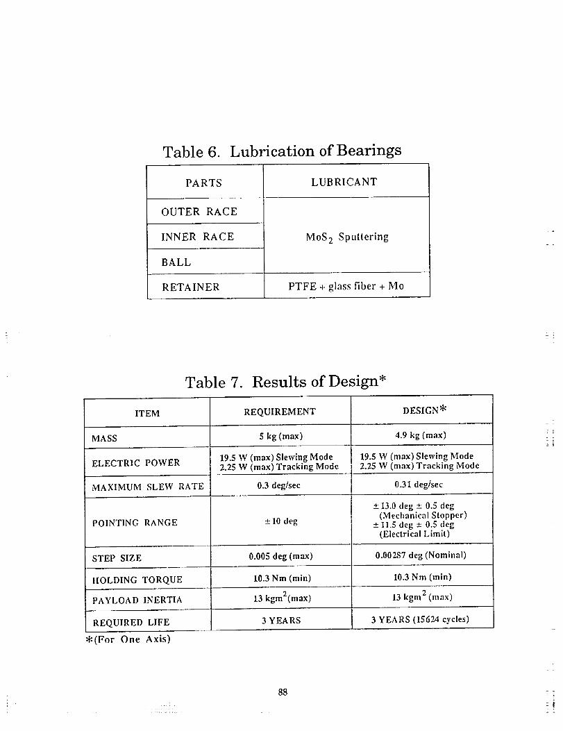
Table 6. Lubrication of Bearings
PA RTS
==
OUTER RACE
INNER RACE
BALL
LUBRICANT
MoS 2 Sputtering
RETAINER PTFE + glass fiber + Mo
Table 7. Results of Design*, =
ITEM REQUIREMENT DESIGN _
MASS 5 kg (max) 4.9 kg (max),r.
ELECTRIC POWER 19.5 W (max) Slewing Mode 19.5 W (max) Slewing Mode2.25 W (max) Tracking Mode 2.25 W (max) Tracking Mode
MAXIMUM SLEW RATE 0.3 deglsec 0.31 deg/sec
-+13.0 deg +_.0.5 deg(Mechanical Slopper)
POINTING RANGE ---10 deg +--11.5 deg -+ 0.5 deg(Electrical Limit)
STEP SIZE 0.005 deg (max) 0.00287 deg (Nominal)
HOLDING TORQUE 10.3 Nm (min) 10.3 Nm (rain)
PAYLOAD INERTIA 13 kgm2(max) 13 kgm 2 (max)
REQUIRED LIFE 3 YEARS 3 YEARS (15624 cycles)
*(For One Axis)
88i
-r-'_
89
IFunciona iVibaoTest Test
Life Test
Thermal- 1
Vacuum
Test l
/
Figure 6. The Sequence of the Tests
Rotary Encoder
\
Feed-tbrot_h Element_ I-"-..---44
APM EM -.. _,
-Ll_
Dummy Inertia
Couplings
T___]
Figure 7. Configuration of the Functional Test
9O
Lt_
+
+
ou!
+
ORIGINAL PAGE
BLACK AND WHITE PHOTOGRAPH
z,
r_Q
o
b_.F_I
J=
_Q
O ,
91
ORIGINAL PAGE IS
OF POOR QUALITY
z _
d _
L,.1
,,
0 E
r._ z _
0_ ,. F. _'r.
zo
,x_ ;-
_r
z -_'_
_: _ _ -H "c_.
r_
g _ z
6 c_
F-
_g z
A
_I r_N E_ _ z
N
_g_z
o
0
..J
7
Z _
=.
Z
°.E
EZ
EZm
v
Ez
E
?
=
Z
E
Ez
e,,
Op.oz
t_
o
92